WO2014199983A1 - 輻射パネル装置 - Google Patents
輻射パネル装置 Download PDFInfo
- Publication number
- WO2014199983A1 WO2014199983A1 PCT/JP2014/065348 JP2014065348W WO2014199983A1 WO 2014199983 A1 WO2014199983 A1 WO 2014199983A1 JP 2014065348 W JP2014065348 W JP 2014065348W WO 2014199983 A1 WO2014199983 A1 WO 2014199983A1
- Authority
- WO
- WIPO (PCT)
- Prior art keywords
- bridge
- heat medium
- panel
- width direction
- panel device
- Prior art date
- Legal status (The legal status is an assumption and is not a legal conclusion. Google has not performed a legal analysis and makes no representation as to the accuracy of the status listed.)
- Ceased
Links
Images


Classifications
-
- F—MECHANICAL ENGINEERING; LIGHTING; HEATING; WEAPONS; BLASTING
- F24—HEATING; RANGES; VENTILATING
- F24D—DOMESTIC- OR SPACE-HEATING SYSTEMS, e.g. CENTRAL HEATING SYSTEMS; DOMESTIC HOT-WATER SUPPLY SYSTEMS; ELEMENTS OR COMPONENTS THEREFOR
- F24D3/00—Hot-water central heating systems
- F24D3/12—Tube and panel arrangements for ceiling, wall, or underfloor heating
- F24D3/16—Tube and panel arrangements for ceiling, wall, or underfloor heating mounted on, or adjacent to, a ceiling, wall or floor
-
- F—MECHANICAL ENGINEERING; LIGHTING; HEATING; WEAPONS; BLASTING
- F24—HEATING; RANGES; VENTILATING
- F24D—DOMESTIC- OR SPACE-HEATING SYSTEMS, e.g. CENTRAL HEATING SYSTEMS; DOMESTIC HOT-WATER SUPPLY SYSTEMS; ELEMENTS OR COMPONENTS THEREFOR
- F24D19/00—Details
- F24D19/0002—Means for connecting central heating radiators to circulation pipes
- F24D19/0009—In a two pipe system
- F24D19/0012—Comprising regulation means
-
- F—MECHANICAL ENGINEERING; LIGHTING; HEATING; WEAPONS; BLASTING
- F24—HEATING; RANGES; VENTILATING
- F24D—DOMESTIC- OR SPACE-HEATING SYSTEMS, e.g. CENTRAL HEATING SYSTEMS; DOMESTIC HOT-WATER SUPPLY SYSTEMS; ELEMENTS OR COMPONENTS THEREFOR
- F24D19/00—Details
- F24D19/0002—Means for connecting central heating radiators to circulation pipes
- F24D19/0017—Connections between supply and inlet or outlet of central heating radiators
-
- F—MECHANICAL ENGINEERING; LIGHTING; HEATING; WEAPONS; BLASTING
- F24—HEATING; RANGES; VENTILATING
- F24D—DOMESTIC- OR SPACE-HEATING SYSTEMS, e.g. CENTRAL HEATING SYSTEMS; DOMESTIC HOT-WATER SUPPLY SYSTEMS; ELEMENTS OR COMPONENTS THEREFOR
- F24D19/00—Details
- F24D19/0002—Means for connecting central heating radiators to circulation pipes
- F24D19/0073—Means for changing the flow of the fluid inside a radiator
-
- F—MECHANICAL ENGINEERING; LIGHTING; HEATING; WEAPONS; BLASTING
- F24—HEATING; RANGES; VENTILATING
- F24D—DOMESTIC- OR SPACE-HEATING SYSTEMS, e.g. CENTRAL HEATING SYSTEMS; DOMESTIC HOT-WATER SUPPLY SYSTEMS; ELEMENTS OR COMPONENTS THEREFOR
- F24D19/00—Details
- F24D19/02—Arrangement of mountings or supports for radiators
- F24D19/022—Constructional details of supporting means for radiators
- F24D19/0236—Water tubes or pipes forming part of the supporting means
-
- F—MECHANICAL ENGINEERING; LIGHTING; HEATING; WEAPONS; BLASTING
- F24—HEATING; RANGES; VENTILATING
- F24F—AIR-CONDITIONING; AIR-HUMIDIFICATION; VENTILATION; USE OF AIR CURRENTS FOR SCREENING
- F24F5/00—Air-conditioning systems or apparatus not covered by F24F1/00 or F24F3/00, e.g. using solar heat or combined with household units such as an oven or water heater
- F24F5/0089—Systems using radiation from walls or panels
- F24F5/0092—Systems using radiation from walls or panels ceilings, e.g. cool ceilings
-
- F—MECHANICAL ENGINEERING; LIGHTING; HEATING; WEAPONS; BLASTING
- F28—HEAT EXCHANGE IN GENERAL
- F28D—HEAT-EXCHANGE APPARATUS, NOT PROVIDED FOR IN ANOTHER SUBCLASS, IN WHICH THE HEAT-EXCHANGE MEDIA DO NOT COME INTO DIRECT CONTACT
- F28D1/00—Heat-exchange apparatus having stationary conduit assemblies for one heat-exchange medium only, the media being in contact with different sides of the conduit wall, in which the other heat-exchange medium is a large body of fluid, e.g. domestic or motor car radiators
- F28D1/02—Heat-exchange apparatus having stationary conduit assemblies for one heat-exchange medium only, the media being in contact with different sides of the conduit wall, in which the other heat-exchange medium is a large body of fluid, e.g. domestic or motor car radiators with heat-exchange conduits immersed in the body of fluid
- F28D1/04—Heat-exchange apparatus having stationary conduit assemblies for one heat-exchange medium only, the media being in contact with different sides of the conduit wall, in which the other heat-exchange medium is a large body of fluid, e.g. domestic or motor car radiators with heat-exchange conduits immersed in the body of fluid with tubular conduits
- F28D1/047—Heat-exchange apparatus having stationary conduit assemblies for one heat-exchange medium only, the media being in contact with different sides of the conduit wall, in which the other heat-exchange medium is a large body of fluid, e.g. domestic or motor car radiators with heat-exchange conduits immersed in the body of fluid with tubular conduits the conduits being bent, e.g. in a serpentine or zig-zag
- F28D1/0475—Heat-exchange apparatus having stationary conduit assemblies for one heat-exchange medium only, the media being in contact with different sides of the conduit wall, in which the other heat-exchange medium is a large body of fluid, e.g. domestic or motor car radiators with heat-exchange conduits immersed in the body of fluid with tubular conduits the conduits being bent, e.g. in a serpentine or zig-zag the conduits having a single U-bend
-
- F—MECHANICAL ENGINEERING; LIGHTING; HEATING; WEAPONS; BLASTING
- F28—HEAT EXCHANGE IN GENERAL
- F28D—HEAT-EXCHANGE APPARATUS, NOT PROVIDED FOR IN ANOTHER SUBCLASS, IN WHICH THE HEAT-EXCHANGE MEDIA DO NOT COME INTO DIRECT CONTACT
- F28D1/00—Heat-exchange apparatus having stationary conduit assemblies for one heat-exchange medium only, the media being in contact with different sides of the conduit wall, in which the other heat-exchange medium is a large body of fluid, e.g. domestic or motor car radiators
- F28D1/02—Heat-exchange apparatus having stationary conduit assemblies for one heat-exchange medium only, the media being in contact with different sides of the conduit wall, in which the other heat-exchange medium is a large body of fluid, e.g. domestic or motor car radiators with heat-exchange conduits immersed in the body of fluid
- F28D1/04—Heat-exchange apparatus having stationary conduit assemblies for one heat-exchange medium only, the media being in contact with different sides of the conduit wall, in which the other heat-exchange medium is a large body of fluid, e.g. domestic or motor car radiators with heat-exchange conduits immersed in the body of fluid with tubular conduits
- F28D1/047—Heat-exchange apparatus having stationary conduit assemblies for one heat-exchange medium only, the media being in contact with different sides of the conduit wall, in which the other heat-exchange medium is a large body of fluid, e.g. domestic or motor car radiators with heat-exchange conduits immersed in the body of fluid with tubular conduits the conduits being bent, e.g. in a serpentine or zig-zag
- F28D1/0477—Heat-exchange apparatus having stationary conduit assemblies for one heat-exchange medium only, the media being in contact with different sides of the conduit wall, in which the other heat-exchange medium is a large body of fluid, e.g. domestic or motor car radiators with heat-exchange conduits immersed in the body of fluid with tubular conduits the conduits being bent, e.g. in a serpentine or zig-zag the conduits being bent in a serpentine or zig-zag
-
- F—MECHANICAL ENGINEERING; LIGHTING; HEATING; WEAPONS; BLASTING
- F28—HEAT EXCHANGE IN GENERAL
- F28F—DETAILS OF HEAT-EXCHANGE AND HEAT-TRANSFER APPARATUS, OF GENERAL APPLICATION
- F28F1/00—Tubular elements; Assemblies of tubular elements
- F28F1/10—Tubular elements and assemblies thereof with means for increasing heat-transfer area, e.g. with fins, with projections, with recesses
- F28F1/12—Tubular elements and assemblies thereof with means for increasing heat-transfer area, e.g. with fins, with projections, with recesses the means being only outside the tubular element
- F28F1/14—Tubular elements and assemblies thereof with means for increasing heat-transfer area, e.g. with fins, with projections, with recesses the means being only outside the tubular element and extending longitudinally
- F28F1/22—Tubular elements and assemblies thereof with means for increasing heat-transfer area, e.g. with fins, with projections, with recesses the means being only outside the tubular element and extending longitudinally the means having portions engaging further tubular elements
-
- F—MECHANICAL ENGINEERING; LIGHTING; HEATING; WEAPONS; BLASTING
- F28—HEAT EXCHANGE IN GENERAL
- F28F—DETAILS OF HEAT-EXCHANGE AND HEAT-TRANSFER APPARATUS, OF GENERAL APPLICATION
- F28F2255/00—Heat exchanger elements made of materials having special features or resulting from particular manufacturing processes
- F28F2255/16—Heat exchanger elements made of materials having special features or resulting from particular manufacturing processes extruded
-
- Y—GENERAL TAGGING OF NEW TECHNOLOGICAL DEVELOPMENTS; GENERAL TAGGING OF CROSS-SECTIONAL TECHNOLOGIES SPANNING OVER SEVERAL SECTIONS OF THE IPC; TECHNICAL SUBJECTS COVERED BY FORMER USPC CROSS-REFERENCE ART COLLECTIONS [XRACs] AND DIGESTS
- Y02—TECHNOLOGIES OR APPLICATIONS FOR MITIGATION OR ADAPTATION AGAINST CLIMATE CHANGE
- Y02B—CLIMATE CHANGE MITIGATION TECHNOLOGIES RELATED TO BUILDINGS, e.g. HOUSING, HOUSE APPLIANCES OR RELATED END-USER APPLICATIONS
- Y02B30/00—Energy efficient heating, ventilation or air conditioning [HVAC]
Definitions
- the present invention relates to a radiation panel device that performs radiation heating and radiation cooling.
- a radiant panel device formed by including a plurality of panels through which a liquid heat medium such as water can flow is known.
- each panel is provided with radiation by circulating a heat medium between a plurality of panels and a separately installed heat source. It is possible to perform air conditioning.
- Patent Document 1 a plurality of radiant panel materials in which a heat medium circulation pipe through which a heat medium circulates is housed in a panel are provided, and the heat medium is circulated through the heat medium circulation pipe of the radiant panel material.
- a radiation panel device that radiates radiant heat is disclosed.
- Patent Document 2 discloses a radiation panel device in which the entire bridge is exposed below the ceiling and the bottom plate portion of the bridge is formed in a V shape.
- an object of the present invention is to provide a radiation panel device capable of suppressing the scattering of water droplets around the device even when water droplets or the like adhere to the bridge.
- One aspect of the present invention includes a horizontally installed bridge, a plurality of panels suspended from the bridge, and a heat medium circulation pipe disposed in each panel and connected on the bridge, the heat medium circulation pipe Is a radiation panel device that provides radiation to each panel by connecting a heat source to circulate the heat medium, and the lower surface portion of the bridge has a pair of slopes that slope downward toward the center in the width direction.
- the panel is provided on both sides in the width direction, and the panel is arranged on the lower surface of the bridge with one end in the width direction facing one inclined portion of the bridge and the other end facing the other inclined portion. It is attached.
- the corner portion where the pair of inclined portions are connected is positioned at least on the inner side in the width direction of the bridge and the panel. Therefore, when water droplets adhering to the lower surface of the bridge fall from the corner portion, there is a distance from the corner portion to the outer side in the width direction, so that the moving water droplet is prevented from moving outward in the width direction of the panel. . Moreover, even when a water drop falls on a floor or a dish or the like installed on the floor, the splash of the water drop can be prevented from scattering to the outside in the width direction due to the distance.
- the lower surface portion of the bridge may be formed in a V shape formed by connecting the lower ends of the pair of inclined portions. According to this, it becomes possible to drop most of the water droplets on the lower surface portion from the corner portion formed by the connection of the pair of inclined portions, and the width in which the water droplet falls can be made narrower than the width of the bridge.
- the bridge may be formed in an equilateral V-shape in which the pair of inclined portions are symmetric. According to this, water drops on the lower surface of the bridge can be dropped from the central portion in the bridge width direction and can be reliably received by a dish or the like installed on the floor.
- the bridge may be provided with fasteners for fastening the panel at both ends in the panel width direction, which are on the upper side of the inclined portion, and a passage portion through which the heat medium flow pipe is inserted is provided at the center in the panel width direction.
- the heat medium circulation pipe and the fastener are provided apart from each other, and it is possible to suppress the occurrence of condensation around the fastener and the fastener due to the heat effect of the heat medium circulation pipe. It is possible to suppress the occurrence of rust on the fastener.
- the fastener is provided above the center of the inclined portion, even when dew condensation occurs on the inside of the bridge, the generated water droplets fall along the slope, and the water droplets extend around the fastener for a long time. Can be suppressed.
- the upper part of the bridge may be covered with a cover member. According to this, the heat medium flow pipe on the bridge is covered with the cover member, and can be made less susceptible to unexpected influences and external influences such as dust. It also improves the appearance.
- the bridge is laid horizontally in a state of facing the ceiling of the living room, and the heat medium flow pipe includes a header portion that uniformly supplies the heat medium toward the panel, and at least a part of the header portion is a cover member. And may be disposed toward the ceiling. According to this, the heat medium circulation pipe can be connected to the heat source via the ceiling, and the exposure of the heat medium circulation pipe can be suppressed.
- the bridge is fixed to the ceiling via a support member, and the support member may be provided with an adjustment mechanism capable of adjusting the distance between the bridge and the ceiling steplessly or in multiple steps. According to this, it can respond to various living rooms with different ceiling heights.
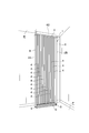
- FIG. 1 is a perspective view showing a state in which a radiation panel device according to an embodiment of the present invention is installed.
- FIG. 2 is a perspective view showing the periphery of the bridge of the radiant panel device.
- FIG. 3 is a plan view of the radiation panel device.
- FIG. 4 is a side view of the radiation panel device.
- FIG. 5 is a perspective view showing an upper portion of the bridge.
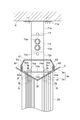
- FIG. 6 is a cross-sectional view taken along line VI-VI in FIG. 7 is a cross-sectional view taken along line VII-VII in FIG.
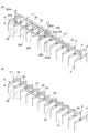
- FIG. 8 is a perspective view showing each series piping system.
- FIG. 9 is a perspective view showing each series piping system.
- 10A and 10B are diagrams showing the header portion, where FIG. 10A is a plan view of the header portion, and FIG. 10B is a side view of the header portion.
- the radiant panel device 1 is a device that is installed in, for example, a corner of a building room and performs radiant heating or radiant cooling.
- the radiant panel device 1 includes a plurality of long and flat panels 4 and a heat medium flow pipe 5 (see FIG. 2) disposed in each of the panels 4. They are connected to each other and further connected to the heat source H (see FIG. 10) through the pipes 100a and 100b to form a heat medium circulation line.
- the radiant panel device 1 includes a plurality of panels 4 and a heat medium flow pipe 5, a pair of support columns 2 ⁇ / b> A and 2 ⁇ / b> B that are erected in a vertical direction between a ceiling plate R and a floor plate F of a living room, A bridge 3 that holds the plurality of panels 4 and a dew condensation water receiving member 6 that is provided below the panels 4 and on the floor plate F and receives the dew condensation water. .
- the pillars 2A and 2B include a pillar body 8 having a length that reaches from the floor board F to the ceiling board R, and a column base member 9 that is externally fitted to the lower end of the pillar body 8 and fixed to the floor board F.
- the condensed water receiving member 6 communicates with a drain pipe (not shown), and the condensed water flowing down along the panel 4 is collected in the condensed water receiving member 6 and discharged outside through the drain pipe.
- the bridge 3 holds a plurality of panels 4 suspended in an upright state in a state of being arranged in a horizontal direction at a predetermined interval. Note that the predetermined interval, the number of the panels 4 and the like can be appropriately determined according to the size and height of the living room or the required performance.
- the bridge 3 is also referred to as an “upper frame”.
- the bridge 3 is erected on a long support plate 3 a extending in the horizontal direction Dh which is the thickness direction of the panel 4, and an upper surface 3 f of the support plate 3 a. And a pair of rib walls 3b.
- the pair of rib walls 3b extend along the longitudinal direction of the support plate 3a and are arranged in parallel to face each other.
- a claw 3p that engages with the cover member 60 is provided at the upper ends of the pair of rib walls 3b.
- the bridge 3 is formed by extruding a metal such as aluminum or stainless steel.
- the support plate 3a has a V-shaped cross section, and the lower surface (lower surface portion) 3g is inclined downward toward the corner portion (width direction center portion) 3h.
- a pair of inclined portions 3j, 3k is provided on both sides in the width direction.
- the corner 3h is formed by connecting the lower ends of the pair of inclined portions 3j and 3k.
- the lengths in the width direction of the pair of inclined portions 3j, 3k are the same, and the inclination angles from the horizontal plane substantially parallel to the floor board F and the ceiling board R are the same. That is, the support plate 3a is formed in an equilateral V-shape in which the pair of inclined portions 3j and 3k are symmetrical.
- the inclination angle of the pair of inclined portions 3j, 3k is 15 to 45 degrees, and more preferably around 30 degrees.
- the pair of inclined portions 3j and 3k of the support plate 3a is formed by further bending a single rectangular steel plate formed by extruding a metal such as aluminum. Specifically, the pair of inclined portions 3j and 3k are formed by bending the steel plate in the width direction central portion (corner portion 3h) as a boundary (fold line).
- the support plate 3a has an inner central portion 3d sandwiched between the pair of rib walls 3b and a pair of flange portions 3e projecting outward from the rib walls 3b.
- a through hole (passing portion) 3c is formed at each position of the central portion 3d facing each panel 4 so as to cut out the corner portion 3h, and in the vicinity of the pair of rib walls 3b.
- a pair of fastening holes 3m into which bolts (fasteners) 78 for fastening the panel 4 are inserted are provided.
- the heat medium flow pipe 5 is passed through the through hole 3c.
- screw receiving portions 3x for screwing the lid portion 75 are provided at both ends of the support plate 3a.
- the support plate 3a may be manufactured by extrusion molding, and the screw receiving portion 3x is provided over the entire longitudinal direction of the support plate 3a.
- the panel 4 includes a long cylindrical member 42 that extends in the vertical direction and has a flat cross section, and at least an upper surface of the cylindrical member 42.
- a cap 41 that closes the end face 50 and is held between the support plate 3a is provided.
- the cylindrical member 42 is formed by extruding metal, for example.
- the material of the cylindrical member 42 is not particularly limited, but weight reduction can be realized when it is made of aluminum.
- the upper end surface 50 of the cylindrical member 42 is cut into a substantially V shape so as to correspond to the support plate 3a of the bridge 3, and the panel corner portion (width direction center portion) 50d with its both end portions 50c in the width direction as upper ends.
- a pair of panel inclined portions 50a and 50b that are downwardly inclined toward each other are provided.
- One end of the width direction both ends 50c of the cylindrical member 42 faces one inclined portion 3j of the bridge 3, and the other end of the width direction both ends 50c is the other inclined portion of the bridge 3. It faces 3k.
- the lengths of the pair of panel inclined portions 50a and 50b in the width direction are the same, and the inclination angles from the horizontal plane parallel to the floor board F and the ceiling board R are the same.
- the inclination angle of the pair of panel inclined portions 50a and 50b is 15 to 45 degrees, and more preferably around 30 degrees, similar to the inclination angle of the inclined portions 3j and 3k of the bridge 3.
- the upper end surface 50 of the cylindrical member 42 is provided with a pair of fastening holes 50e into which bolts (fasteners) 78 are screwed. Further, the heat medium flow pipe 5 is accommodated in a region inside the pair of tightening holes 50e.
- the outer surface of the cylindrical member 42 is provided with a plurality of fins 50i protruding in a wave shape in order to increase the heat transfer area to the outside air.
- the plurality of fins 50 i extend in the longitudinal direction of the tubular member 42, that is, in the vertical direction in a state where the tubular member 42 is raised, and the condensed water adhering to the tubular member 42 during cooling is a condensed water receiving member. 6 also has a function of guiding downward toward 6.
- the heat medium flow pipe 5 accommodated in the cylindrical member 42 is substantially U-shaped, and is bent and bent at the lower end side of the cylindrical member 42.
- the part of the heat medium flow pipe 5 that forms the passage through which the heat medium flows downward is the forward path side accommodating part 5a, and the part that forms the path through which the heat medium flows upward is the return path side accommodating part 5b,
- a portion that connects the forward path side accommodating portion 5a and the return path side accommodating portion 5b is a folded portion 5g.
- the forward path side accommodating part 5 a and the return path side accommodating part 5 b are gathered near the center in the width direction of the cylindrical member 42 on the upper end side of the cylindrical member 42.
- the heat medium flow pipe 5 gathered closer to the center passes through the cap 41 attached to the upper end surface 50 of the cylindrical member 42 and the support plate 3 a of the bridge 3 and protrudes above the bridge 3.
- the portions of the heat medium flow pipe 5 that protrude from the upper surface 3f of the bridge 3 are extended portions 5c and 5d.
- the side that communicates with the forward path side accommodating portion 5a is the forward path side extended portion 5c, and the return path side accommodating portion.
- the side that communicates with 5b is a return path extending portion 5d.
- the heat medium flow pipe 5 is made of, for example, a resin pipe having an inner diameter of about 7 mm.
- a resin pipe having an inner diameter of about 7 mm.
- the flexibility is good and it can be bent to a small radius, and the processing of the heat medium flow pipes 5 and the assembly work to the tubular member 42 can be easily performed.
- a resin pipe a cross-linked polyethylene pipe, a polybudene, or a polyolefin-based resin material can be employed.
- the cap 41 is a plate that covers the upper end surface 50 of the cylindrical member 42, and is bent in a substantially V shape to correspond to the support plate 3a in a side view.
- the cap 41 is disposed between the support plate 3 a of the bridge 3 and the upper end surface 50 of the panel 4, and is clamped between the support plate 3 a and the panel 4 by being fastened with bolts 78.
- the cap 41 includes a pair of cap inclined portions 41a and 41b that are inclined downward toward the cap corner portion (center portion in the width direction) 41d with the width direction both end portions 41c as upper ends.
- One end of the width direction both ends 41c of the cap 41 faces one inclined portion 3j of the bridge 3, and the other end of the width direction both ends 41c faces the other inclined portion 3k of the bridge 3.
- the inclination angles of the pair of cap inclination portions 41a and 41b are substantially the same as the inclination angles of the pair of inclination portions 3j and 3k of the bridge 3 and the pair of panel inclination portions 50a and 50b of the cylindrical member 42. Is following the outer periphery of the cylindrical member 42.
- the cap 41 is provided with a through hole 41f penetrating so as to cut out the cap corner portion 41d, and the heat medium flow pipe 5 is passed through the through hole 41f. Further, a pair of tightening holes 41g into which the bolts 78 are inserted are provided in the vicinity of both end portions 41c in the width direction of the cap 41.
- the cap 41 is made of a resin whose main component is, for example, ASA (acrylonitrile-styrene-acrylate), AES (acrylonitrile-ethylenepropylene diene-styrene), and the like, and is formed between the tubular member 42 and the bridge 3. It has a function to suppress heat transfer.
- ASA acrylonitrile-styrene-acrylate
- AES acrylonitrile-ethylenepropylene diene-styrene
- the upper part of the bridge 3 is covered with a cover member 60 and fixed to the ceiling plate R via a support member 70.
- the support member 70 also functions as an adjustment mechanism that adjusts the distance between the bridge 3 and the ceiling plate R.
- a multistage adjustment mechanism is illustrated, but a stepless adjustment mechanism can also be used.
- the support member 70 has a ceiling mounting member 71 fixed to the ceiling plate R and a bridge mounting member 72 fixed to the bridge 3.
- the ceiling mounting member 71 includes a flat plate portion 71a that is screwed in contact with the ceiling plate R, and a rectangular plate-shaped adjustment portion 71e that extends vertically downward from the flat plate portion 71a.
- the adjustment portion 71e is provided with three adjustment holes 71f arranged in the vertical direction for height adjustment.
- the adjustment hole 71f is a long hole that is vertically long so that fine adjustment is possible.
- the bridge mounting member 72 is disposed on the upper surface 3f side of the support plate 3a, is erected from the base plate portion 72a fixed to the support plate 3a by bolts 74a, and the base plate portion 72a, and protrudes through the cover member 60.
- the adjustment portion 72c is provided with three adjustment holes 72d arranged in the vertical direction for height adjustment.
- the adjustment hole 71f of the adjustment part 71e of the ceiling attachment member 71 and the adjustment hole 72d of the adjustment part 72c of the bridge attachment member 72 are appropriately selected.
- the height is adjusted by aligning with each other, and the shaft portion of the bolt 73a is fastened to the aligned adjustment holes 71f and 72d by fastening with the insertion nut 73c.
- a pair of spacers 74b having a substantially triangular cross section that absorbs the inclination angles of the inclined portions 3j and 3k and stabilizes the base plate portion 72a of the bridge mounting member 72 are disposed on the upper surface 3f of the bridge 3.
- the base plate portion 72a is placed on the pair of spacers 74b and fixed to the bridge 3 by bolts 74a.
- the bolt 74 a passes through the bridge 3 and is screwed to the column body 8 of the column 2 ⁇ / b> A disposed below the bridge 3.
- the cover member 60 that covers the upper surface 3f of the bridge 3 extends along the longitudinal direction of the bridge 3, and includes a ceiling plate R, a horizontal rectangular plate-like roof portion 61, and a pair of rectangular plate shapes that are perpendicular to the ceiling plate R. And a pair of connecting portions 63 having a rectangular plate shape for connecting the roof portion 61 and the rising portion 62 to each other.
- a heat insulating material (not shown) is provided inside the cover member 60, and the temperature change of the heat medium on the upper surface 3 f of the bridge 3 is suppressed.
- the roof portion 61 is formed with an insertion hole 61a into which the adjustment portion 72c of the bridge attachment member 72 is inserted.
- the roof portion 61 is provided with a through hole 61x through which the pipes 100a and 100b connected to the heat medium flow pipe 5 pass.
- the pipes 100 a and 100 b are connected to the heat source H (see FIG. 10) and the heat medium flow pipe 5, and the heat medium is supplied toward each panel 4.
- a wiring cover 77 is erected between the cover member 60 and the ceiling plate R so as to sandwich the support member 70 and the pipes 100a and 100b. Since the wiring cover 77 is erected, the support member 70 and the pipes 100a and 100b are hardly exposed, and external influences such as unexpected impact and dust are suppressed, and the aesthetics are improved.
- a claw 62a that engages with the claw 3p of the rib wall 3b is formed.
- the cover member 60 is difficult to be pulled upward.
- a protruding piece 62b protruding inward is provided on the upper portion of the rising portion 62. Since the protruding piece 62b is in contact with the upper end of the rib wall 3b in the engaged state, the protruding piece 62b and the claw 62a Thus, the claw 3p of the rib wall 3b is sandwiched, and the fixing state of the cover member 60 to the bridge 3 can be strengthened.
- the cover member 60 and the bridge 3 are fixed by engaging the claw 62a of the rising portion 62 and the claw 3p of the rib wall 3b.
- the projecting portion 62 projects outward from the rising portion 62 that is both ends of the width direction 60. Since the flange portion 3e projects outward, the structure of the upper portion of the bridge 3 becomes difficult to visually recognize, and the appearance can be improved.
- the heat medium flow pipe 5 accommodated in the panel 4 has an outward path-side extension part 5c and a return path-side extension part 5d protruding above the bridge 3, and in the longitudinal direction of the bridge 3 above the bridge 3, respectively. Curved towards.
- the return path extending portion 5 d is connected to the forward path extending portion 5 c of the other heat medium flow pipe 5 accommodated in the other panel 4, and the forward path extending portion 5 c is connected to the other panel 4. Is connected to the return-side extending part 5d of the other heat medium flow pipe 5 accommodated in the pipe.
- the plurality of heat medium flow pipes 5 are connected in series by the connection of the return path side extension part 5d and the forward path side extension part 5c, and the series piping systems L1, L2, L3, and L4 are formed.
- the forward-side extending portion 5c protruding from the first tubular member 42 from the left (see FIG. 8A)
- the branch pipe 252a provided in the parallel distribution section 252 of the upstream header section 250 into which the heat medium is introduced is connected.
- the forward-side extending portion 5c protrudes from the cylindrical member 42 as a return-side extending portion 5d (see FIG. 8B) through a substantially U-shaped channel accommodated in the cylindrical member 42.
- the return path extending portion 5d is connected to the forward path extending portion 5c protruding from the fifth cylindrical member 42 from the left, and is a cylindrical member as the return path extending portion 5d via a substantially U-shaped channel. It sticks out from 42.
- the return-side extending portion 5d is connected to the outward-path-side extending portion 5c protruding from the fourth tubular member 42 from the right, and the return-side extending portion 5d (FIG. 9) via a substantially U-shaped channel. It protrudes from the cylindrical member 42 as (b).
- the return path extending portion 5d is connected to a branch pipe 253a provided in the parallel merge portion 253 of the downstream header portion 251 from which the heat medium is discharged.
- the other serial piping systems L2 to L4 are connected to the branch pipe 252a provided in the parallel distribution section 252 of the upstream header section 250, and are connected to the downstream header section 251 in the same manner as the serial piping system L1. It is connected to a branch pipe 253 a provided in the parallel junction 253.
- header parts 250 and 251 will be described in detail with reference to FIG. In addition, since the header part 250 and the header part 251 are substantially the same structures, the description which overlaps is demonstrated by the structure of the header part 250, and description of the header part 251 is abbreviate
- the header part 250 includes a parallel distribution part 252, a joint part 254 connected to the parallel distribution part 252, a joint part 255 connected to the pipe 100a connected to the heat source H, And a header portion pipe 256 connecting the joint portion 254 and the joint portion 255.
- the parallel distributor 252 has a cylindrical joint pipe 252g for connecting the joint part 254, a main body pipe 252f that receives the heat medium via the joint pipe 252g, a branch from the main body pipe 252f, and is introduced into the main body pipe 252f. And a plurality of branch pipes 252a for distributing the heat medium to the serial piping systems L1 to L4.
- the header section 250 is connected to the heat source H via the pipe 100a, and evenly distributes the heat medium sent from the heat source H to the respective series pipe systems L1 to L4. . Further, the header portion 251 is connected to the heat source H through the pipe 100b, aggregates the heat medium discharged from each series piping system L1 to L4, and returns the heat medium to the heat source H.
- the joint part 255 of the header part 250 is connected to the pipe 100a via the joint pipe 255b.
- the pipe 100a is connected to the heat source H from the ceiling plate R through the back of the ceiling.
- the joint pipe 255 b extends through the cover member 60 toward the ceiling plate R.
- the joint part 255 of the header part 251 is connected to the pipe 100b via the joint pipe 255b.
- the pipe 100b is connected to the heat source H from the ceiling plate R through the back of the ceiling.
- the bridge 3 laid horizontally in a state of being opposed to the ceiling of a living room or the like between the columns 2 ⁇ / b> A and 2 ⁇ / b> B.
- a pair of inclined portions 3j and 3k are provided which have both end portions 3i in the width direction as upper ends and are inclined downward toward a corner portion (central portion in the width direction) 3h.
- the bridge 3 of the radiation panel device 1 is formed in a V shape by a pair of inclined portions 3j, 3k.
- most of the water droplets (condensation water) adhering to the lower surface 3g can be dropped from the corner 3h formed by connecting the pair of inclined portions 3j and 3k. Therefore, the width of the point where the water droplet falls can be made narrower than in the case where the corner 3h has a predetermined width instead of a sharp shape.
- the splash of the water droplet to a living room side can be reduced by providing the corner
- the pair of inclined portions 3j and 3k are formed in an equilateral V-shape that is symmetrical with respect to the left and right. It can be dropped from the center and can be reliably received by the condensed water receiving member 6. Moreover, since the cylindrical member 42 is also left-right symmetric, the external appearance from both sides is the same, and there is little discomfort even if it is used as a partition in the center of the living room. In addition, even if it is a limited space by making a pair of inclination part 3j, 3k into an equilateral V shape, the inclination angle of a pair of inclination part 3j, 3k can fully be taken.
- bolt (fastener) 78 which fastens the cylindrical member 42 is inserted are more than the through-hole 3c through which the heat-medium distribution
- the upper portion of the bridge 3 is covered with the cover member 60, and both ends in the longitudinal direction are closed with the lid portions 75. Can be made less susceptible to It also improves the appearance.
- the radiation panel device 1 includes the header portion 250 that uniformly supplies the heat medium toward the respective cylindrical members 42, and the joint pipe 255 b that is a part of the header portion 250 is illustrated in FIG. 10, the heat medium flow pipe 5 can be connected to the heat source H through the back of the ceiling by being disposed toward the ceiling plate R through the cover member 60, and the heat The exposure of the medium flow pipe 5 can be suppressed.
- the portion that penetrates the cover member 60 may be another portion of the header portion 250.
- the bridge 3 is fixed to the ceiling board R via the support member 70.
- the bridge 3 is supported by the column base member 9 (see FIG. 2) fixed to the floor plate F as well as being fixed to the ceiling plate R by the support member 70, but the position cannot be adjusted by the support member 70 described above.
- such trouble can be avoided. .
- the radiant panel device according to the present invention may be modified from the radiant panel device according to the embodiment or applied to other devices without changing the gist described in each claim.
- the bridge 3 has exemplified the aspect in which both the upper surface 3f and the lower surface 3g are inclined, a configuration in which only the lower surface is inclined may be employed.
- the cross-sectional shape of the bridge 3 is not only the above-mentioned equilateral V-shape or a shape in which the corner 3h is offset to any one, but a horizontal portion is provided between the pair of inclined portions 3j and 3k, thereby It is also possible to employ a configuration having the corners.
- the collar part 3e does not necessarily need to incline like the pair of incline parts 3j and 3k, and may protrude in the horizontal direction. In this case, it is possible to embed the eaves portion projecting in the horizontal direction in the ceiling, so that the upper part of the bridge 3 can be arranged behind the ceiling.
- the member that receives the falling water droplets has been described as the condensed water receiving member 6 that is a member communicating with the drain pipe, the member is not necessarily limited thereto, and may be a sponge or the like.
- the position (height) adjustment by the ceiling attachment member 71 and the bridge attachment member 72 has been described as being performed by changing the combination of the adjustment holes 71f and 72d (multi-stage position adjustment is performed). Instead, stepless position adjustment in which both members are slid and fixed at an arbitrary position may be performed.
- SYMBOLS 1 Radiant panel apparatus, 3 ... Bridge, 3g ... Bottom surface of bridge, 3h ... Corner of bridge, 3j, 3k ... Inclined part, 4 ... Panel, 5 ... Heat transfer pipe, 60 ... Cover member, 70 ... Support member (Adjustment mechanism), 78 ... Bolt (fastener), 250, 251 ... Header part, R ... Ceiling board.
Landscapes
- Engineering & Computer Science (AREA)
- Physics & Mathematics (AREA)
- Mechanical Engineering (AREA)
- General Engineering & Computer Science (AREA)
- Thermal Sciences (AREA)
- Combustion & Propulsion (AREA)
- Chemical & Material Sciences (AREA)
- Life Sciences & Earth Sciences (AREA)
- Sustainable Development (AREA)
- Geometry (AREA)
- Steam Or Hot-Water Central Heating Systems (AREA)
- Devices For Blowing Cold Air, Devices For Blowing Warm Air, And Means For Preventing Water Condensation In Air Conditioning Units (AREA)
- Domestic Hot-Water Supply Systems And Details Of Heating Systems (AREA)
Abstract
Description
Claims (7)
- 横設されるブリッジと、前記ブリッジに垂下される複数のパネルと、各パネルに配設されて前記ブリッジ上で連結される熱媒流通管とを備え、該熱媒流通管を熱源に連結して熱媒体を循環させることで各パネルに輻射能を付与する輻射パネル装置であって、
前記ブリッジの下面部は、その幅方向中央部に向けて下り傾斜状となる一対の傾斜部を幅方向両側部に備え、
前記パネルは、幅方向の一方の端部を前記ブリッジの一方の前記傾斜部に対向させると共に他方の端部を他方の前記傾斜部に対向させた状態で前記ブリッジの下面部に取り付けられている、輻射パネル装置。 - 前記ブリッジの下面部は、前記一対の傾斜部の下端部を連結してなるV字状に形成されている、請求項1に記載の輻射パネル装置。
- 前記ブリッジは、前記一対の傾斜部を左右対称状とした等辺V字状に形成されている、請求項2に記載の輻射パネル装置。
- 前記ブリッジは、
前記パネルを留めつける留め具が、前記傾斜部の上部側となるパネル幅方向両端側に設けられ、
前記熱媒流通管を挿通させる通過部がパネル幅方向中央部に設けられている、請求項1~3のいずれか一項に記載の輻射パネル装置。 - 前記ブリッジの上部は、カバー部材に覆われている、請求項1~4のいずれか一項に記載の輻射パネル装置。
- 前記ブリッジは、居室の天井に近接対向した状態で横設されており、
前記熱媒流通管は、前記パネルに向けて熱媒体を均等に供給するヘッダ部を備え、
前記ヘッダ部の少なくとも一部は、前記カバー部材を貫通して天井に向けて配設されている、請求項5に記載の輻射パネル装置。 - 前記ブリッジは、支持部材を介して天井に固定されており、
前記支持部材には、無段又は多段にブリッジと天井との間隔を調整可能な調整機構が設けられている、請求項1~6のいずれか一項に記載の輻射パネル装置。
Priority Applications (3)
| Application Number | Priority Date | Filing Date | Title |
|---|---|---|---|
| KR1020157034500A KR20160018516A (ko) | 2013-06-11 | 2014-06-10 | 복사 패널 장치 |
| EP14810486.2A EP3009749A4 (en) | 2013-06-11 | 2014-06-10 | RADIATION PANEL DEVICE |
| CN201480032996.2A CN105283711B (zh) | 2013-06-11 | 2014-06-10 | 辐射板装置 |
Applications Claiming Priority (2)
| Application Number | Priority Date | Filing Date | Title |
|---|---|---|---|
| JP2013122925A JP6068272B2 (ja) | 2013-06-11 | 2013-06-11 | 輻射パネル装置 |
| JP2013-122925 | 2013-06-11 |
Publications (1)
| Publication Number | Publication Date |
|---|---|
| WO2014199983A1 true WO2014199983A1 (ja) | 2014-12-18 |
Family
ID=52022275
Family Applications (1)
| Application Number | Title | Priority Date | Filing Date |
|---|---|---|---|
| PCT/JP2014/065348 Ceased WO2014199983A1 (ja) | 2013-06-11 | 2014-06-10 | 輻射パネル装置 |
Country Status (6)
| Country | Link |
|---|---|
| EP (1) | EP3009749A4 (ja) |
| JP (1) | JP6068272B2 (ja) |
| KR (1) | KR20160018516A (ja) |
| CN (1) | CN105283711B (ja) |
| TW (1) | TWI621825B (ja) |
| WO (1) | WO2014199983A1 (ja) |
Cited By (1)
| Publication number | Priority date | Publication date | Assignee | Title |
|---|---|---|---|---|
| CN110446902A (zh) * | 2017-03-08 | 2019-11-12 | 公平气候有限责任公司 | 壁挂式辐射冷却装置 |
Families Citing this family (4)
| Publication number | Priority date | Publication date | Assignee | Title |
|---|---|---|---|---|
| JP6887831B2 (ja) * | 2017-03-09 | 2021-06-16 | フクビ化学工業株式会社 | 天井パネル |
| JP6848893B2 (ja) * | 2018-01-29 | 2021-03-24 | ダイキン工業株式会社 | 輻射パネル用の固定具および輻射パネルユニット |
| IT201800007155A1 (it) * | 2018-07-16 | 2020-01-16 | Bobina radiante per climatizzazione a soffitto ed a parete | |
| JP6694199B1 (ja) * | 2019-06-20 | 2020-05-13 | Futaeda株式会社 | 放射パネル |
Citations (5)
| Publication number | Priority date | Publication date | Assignee | Title |
|---|---|---|---|---|
| EP0541947A1 (de) * | 1991-11-11 | 1993-05-19 | Hewing GmbH | Wärmetauscher |
| JP2006153431A (ja) | 2004-10-28 | 2006-06-15 | Asahi Kasei Homes Kk | 冷却パネル |
| JP2010243126A (ja) | 2009-04-09 | 2010-10-28 | Asahi Kasei Homes Co | 輻射パネル装置 |
| JP2011185452A (ja) * | 2010-03-04 | 2011-09-22 | Asahi Kasei Homes Co | 輻射パネル材 |
| JP2012242070A (ja) * | 2011-05-24 | 2012-12-10 | Asahi Kasei Homes Co | 輻射パネル装置 |
Family Cites Families (4)
| Publication number | Priority date | Publication date | Assignee | Title |
|---|---|---|---|---|
| CN102183069A (zh) * | 2010-07-06 | 2011-09-14 | 马立 | 板盒(管)式辐射板空调 |
| JP5779447B2 (ja) * | 2011-08-17 | 2015-09-16 | 旭化成ホームズ株式会社 | 輻射パネル装置 |
| CN103930732A (zh) * | 2011-10-19 | 2014-07-16 | 因幡电机产业株式会社 | 空调装置 |
| CN202709351U (zh) * | 2012-07-04 | 2013-01-30 | 广东同益电器有限公司 | 一种热泵式辐射空调器 |
-
2013
- 2013-06-11 JP JP2013122925A patent/JP6068272B2/ja not_active Expired - Fee Related
-
2014
- 2014-06-10 EP EP14810486.2A patent/EP3009749A4/en not_active Withdrawn
- 2014-06-10 WO PCT/JP2014/065348 patent/WO2014199983A1/ja not_active Ceased
- 2014-06-10 KR KR1020157034500A patent/KR20160018516A/ko not_active Withdrawn
- 2014-06-10 CN CN201480032996.2A patent/CN105283711B/zh active Active
- 2014-06-11 TW TW103120217A patent/TWI621825B/zh active
Patent Citations (5)
| Publication number | Priority date | Publication date | Assignee | Title |
|---|---|---|---|---|
| EP0541947A1 (de) * | 1991-11-11 | 1993-05-19 | Hewing GmbH | Wärmetauscher |
| JP2006153431A (ja) | 2004-10-28 | 2006-06-15 | Asahi Kasei Homes Kk | 冷却パネル |
| JP2010243126A (ja) | 2009-04-09 | 2010-10-28 | Asahi Kasei Homes Co | 輻射パネル装置 |
| JP2011185452A (ja) * | 2010-03-04 | 2011-09-22 | Asahi Kasei Homes Co | 輻射パネル材 |
| JP2012242070A (ja) * | 2011-05-24 | 2012-12-10 | Asahi Kasei Homes Co | 輻射パネル装置 |
Non-Patent Citations (1)
| Title |
|---|
| See also references of EP3009749A4 * |
Cited By (2)
| Publication number | Priority date | Publication date | Assignee | Title |
|---|---|---|---|---|
| CN110446902A (zh) * | 2017-03-08 | 2019-11-12 | 公平气候有限责任公司 | 壁挂式辐射冷却装置 |
| CN110446902B (zh) * | 2017-03-08 | 2021-07-13 | 公平气候有限责任公司 | 壁挂式辐射冷却装置 |
Also Published As
| Publication number | Publication date |
|---|---|
| CN105283711A (zh) | 2016-01-27 |
| EP3009749A4 (en) | 2016-07-27 |
| JP2014240715A (ja) | 2014-12-25 |
| JP6068272B2 (ja) | 2017-01-25 |
| TW201506345A (zh) | 2015-02-16 |
| KR20160018516A (ko) | 2016-02-17 |
| EP3009749A1 (en) | 2016-04-20 |
| CN105283711B (zh) | 2018-09-14 |
| TWI621825B (zh) | 2018-04-21 |
Similar Documents
| Publication | Publication Date | Title |
|---|---|---|
| JP6068272B2 (ja) | 輻射パネル装置 | |
| US8870135B2 (en) | Universal hanger device | |
| US20160195345A1 (en) | Condensate drain devices for heat exchanger coil and methods for making the same | |
| US12061008B2 (en) | Air diffuser | |
| JP2010243127A (ja) | 輻射パネル装置 | |
| JP5394114B2 (ja) | 輻射パネル装置 | |
| JP2010243128A (ja) | 輻射パネル装置 | |
| US20110056666A1 (en) | Modular panel for the formation of systems for ambient cooling or heating | |
| JP2009300051A (ja) | 天井輻射システム | |
| CN112424534B (zh) | 辐射面板 | |
| JP5816647B2 (ja) | 冷暖房放熱パネルシステム | |
| JP2014105964A (ja) | 結露許容型冷暖房システム | |
| JP5580391B2 (ja) | 全プラスチック樹脂製柵状放熱体の支持構造及び使用する金具 | |
| JP6039589B2 (ja) | 全プラスチック樹脂製柵状放熱体の支持構造に使用する金具 | |
| EP3636069B1 (en) | Gutter for an evaporative pad of a cooling system | |
| JP2016065646A (ja) | 空調用輻射パネルの結露水排水構造 | |
| JP2011185454A (ja) | 輻射パネル装置及び輻射パネル材 | |
| US20070034367A1 (en) | Method and Apparatus for Heating and Cooling | |
| FI89690C (fi) | Uppvaermningssystem | |
| CN215675756U (zh) | 住宅楼的空调排水系统 | |
| EP1674801B1 (de) | Klimaelement | |
| KR101458516B1 (ko) | 건축용 에어컨 실외기 설치구조 | |
| KR102869270B1 (ko) | 차량용 공조장치의 블로워 장치 | |
| CN212613109U (zh) | 冷却建材单元及冷却面板 | |
| JP2006112742A (ja) | 天井輻射システム |
Legal Events
| Date | Code | Title | Description |
|---|---|---|---|
| WWE | Wipo information: entry into national phase |
Ref document number: 201480032996.2 Country of ref document: CN |
|
| 121 | Ep: the epo has been informed by wipo that ep was designated in this application |
Ref document number: 14810486 Country of ref document: EP Kind code of ref document: A1 |
|
| ENP | Entry into the national phase |
Ref document number: 20157034500 Country of ref document: KR Kind code of ref document: A |
|
| NENP | Non-entry into the national phase |
Ref country code: DE |
|
| REEP | Request for entry into the european phase |
Ref document number: 2014810486 Country of ref document: EP |
|
| WWE | Wipo information: entry into national phase |
Ref document number: 2014810486 Country of ref document: EP |