WO2014203438A1 - 画像表示制御装置、画像表示システム、画像表示制御方法及びプログラム - Google Patents
画像表示制御装置、画像表示システム、画像表示制御方法及びプログラム Download PDFInfo
- Publication number
- WO2014203438A1 WO2014203438A1 PCT/JP2014/002072 JP2014002072W WO2014203438A1 WO 2014203438 A1 WO2014203438 A1 WO 2014203438A1 JP 2014002072 W JP2014002072 W JP 2014002072W WO 2014203438 A1 WO2014203438 A1 WO 2014203438A1
- Authority
- WO
- WIPO (PCT)
- Prior art keywords
- mode
- image
- image display
- display control
- displayed
- Prior art date
- Legal status (The legal status is an assumption and is not a legal conclusion. Google has not performed a legal analysis and makes no representation as to the accuracy of the status listed.)
- Ceased
Links
Images





Classifications
-
- G—PHYSICS
- G09—EDUCATION; CRYPTOGRAPHY; DISPLAY; ADVERTISING; SEALS
- G09G—ARRANGEMENTS OR CIRCUITS FOR CONTROL OF INDICATING DEVICES USING STATIC MEANS TO PRESENT VARIABLE INFORMATION
- G09G3/00—Control arrangements or circuits, of interest only in connection with visual indicators other than cathode-ray tubes
- G09G3/20—Control arrangements or circuits, of interest only in connection with visual indicators other than cathode-ray tubes for presentation of an assembly of a number of characters, e.g. a page, by composing the assembly by combination of individual elements arranged in a matrix no fixed position being assigned to or needed to be assigned to the individual characters or partial characters
- G09G3/22—Control arrangements or circuits, of interest only in connection with visual indicators other than cathode-ray tubes for presentation of an assembly of a number of characters, e.g. a page, by composing the assembly by combination of individual elements arranged in a matrix no fixed position being assigned to or needed to be assigned to the individual characters or partial characters using controlled light sources
- G09G3/30—Control arrangements or circuits, of interest only in connection with visual indicators other than cathode-ray tubes for presentation of an assembly of a number of characters, e.g. a page, by composing the assembly by combination of individual elements arranged in a matrix no fixed position being assigned to or needed to be assigned to the individual characters or partial characters using controlled light sources using electroluminescent panels
- G09G3/32—Control arrangements or circuits, of interest only in connection with visual indicators other than cathode-ray tubes for presentation of an assembly of a number of characters, e.g. a page, by composing the assembly by combination of individual elements arranged in a matrix no fixed position being assigned to or needed to be assigned to the individual characters or partial characters using controlled light sources using electroluminescent panels semiconductive, e.g. using light-emitting diodes [LED]
- G09G3/3208—Control arrangements or circuits, of interest only in connection with visual indicators other than cathode-ray tubes for presentation of an assembly of a number of characters, e.g. a page, by composing the assembly by combination of individual elements arranged in a matrix no fixed position being assigned to or needed to be assigned to the individual characters or partial characters using controlled light sources using electroluminescent panels semiconductive, e.g. using light-emitting diodes [LED] organic, e.g. using organic light-emitting diodes [OLED]
-
- G—PHYSICS
- G06—COMPUTING OR CALCULATING; COUNTING
- G06F—ELECTRIC DIGITAL DATA PROCESSING
- G06F3/00—Input arrangements for transferring data to be processed into a form capable of being handled by the computer; Output arrangements for transferring data from processing unit to output unit, e.g. interface arrangements
- G06F3/14—Digital output to display device ; Cooperation and interconnection of the display device with other functional units
- G06F3/1423—Digital output to display device ; Cooperation and interconnection of the display device with other functional units controlling a plurality of local displays, e.g. CRT and flat panel display
-
- G—PHYSICS
- G09—EDUCATION; CRYPTOGRAPHY; DISPLAY; ADVERTISING; SEALS
- G09G—ARRANGEMENTS OR CIRCUITS FOR CONTROL OF INDICATING DEVICES USING STATIC MEANS TO PRESENT VARIABLE INFORMATION
- G09G2320/00—Control of display operating conditions
- G09G2320/02—Improving the quality of display appearance
- G09G2320/0233—Improving the luminance or brightness uniformity across the screen
-
- G—PHYSICS
- G09—EDUCATION; CRYPTOGRAPHY; DISPLAY; ADVERTISING; SEALS
- G09G—ARRANGEMENTS OR CIRCUITS FOR CONTROL OF INDICATING DEVICES USING STATIC MEANS TO PRESENT VARIABLE INFORMATION
- G09G2320/00—Control of display operating conditions
- G09G2320/02—Improving the quality of display appearance
- G09G2320/0257—Reduction of after-image effects
-
- G—PHYSICS
- G09—EDUCATION; CRYPTOGRAPHY; DISPLAY; ADVERTISING; SEALS
- G09G—ARRANGEMENTS OR CIRCUITS FOR CONTROL OF INDICATING DEVICES USING STATIC MEANS TO PRESENT VARIABLE INFORMATION
- G09G2320/00—Control of display operating conditions
- G09G2320/04—Maintaining the quality of display appearance
- G09G2320/043—Preventing or counteracting the effects of ageing
- G09G2320/046—Dealing with screen burn-in prevention or compensation of the effects thereof
-
- G—PHYSICS
- G09—EDUCATION; CRYPTOGRAPHY; DISPLAY; ADVERTISING; SEALS
- G09G—ARRANGEMENTS OR CIRCUITS FOR CONTROL OF INDICATING DEVICES USING STATIC MEANS TO PRESENT VARIABLE INFORMATION
- G09G2320/00—Control of display operating conditions
- G09G2320/06—Adjustment of display parameters
- G09G2320/0606—Manual adjustment
-
- G—PHYSICS
- G09—EDUCATION; CRYPTOGRAPHY; DISPLAY; ADVERTISING; SEALS
- G09G—ARRANGEMENTS OR CIRCUITS FOR CONTROL OF INDICATING DEVICES USING STATIC MEANS TO PRESENT VARIABLE INFORMATION
- G09G2320/00—Control of display operating conditions
- G09G2320/06—Adjustment of display parameters
- G09G2320/0613—The adjustment depending on the type of the information to be displayed
-
- G—PHYSICS
- G09—EDUCATION; CRYPTOGRAPHY; DISPLAY; ADVERTISING; SEALS
- G09G—ARRANGEMENTS OR CIRCUITS FOR CONTROL OF INDICATING DEVICES USING STATIC MEANS TO PRESENT VARIABLE INFORMATION
- G09G2320/00—Control of display operating conditions
- G09G2320/06—Adjustment of display parameters
- G09G2320/0626—Adjustment of display parameters for control of overall brightness
-
- G—PHYSICS
- G09—EDUCATION; CRYPTOGRAPHY; DISPLAY; ADVERTISING; SEALS
- G09G—ARRANGEMENTS OR CIRCUITS FOR CONTROL OF INDICATING DEVICES USING STATIC MEANS TO PRESENT VARIABLE INFORMATION
- G09G2320/00—Control of display operating conditions
- G09G2320/06—Adjustment of display parameters
- G09G2320/0686—Adjustment of display parameters with two or more screen areas displaying information with different brightness or colours
-
- G—PHYSICS
- G09—EDUCATION; CRYPTOGRAPHY; DISPLAY; ADVERTISING; SEALS
- G09G—ARRANGEMENTS OR CIRCUITS FOR CONTROL OF INDICATING DEVICES USING STATIC MEANS TO PRESENT VARIABLE INFORMATION
- G09G2330/00—Aspects of power supply; Aspects of display protection and defect management
- G09G2330/02—Details of power systems and of start or stop of display operation
- G09G2330/025—Reduction of instantaneous peaks of current
-
- G—PHYSICS
- G09—EDUCATION; CRYPTOGRAPHY; DISPLAY; ADVERTISING; SEALS
- G09G—ARRANGEMENTS OR CIRCUITS FOR CONTROL OF INDICATING DEVICES USING STATIC MEANS TO PRESENT VARIABLE INFORMATION
- G09G2330/00—Aspects of power supply; Aspects of display protection and defect management
- G09G2330/02—Details of power systems and of start or stop of display operation
- G09G2330/026—Arrangements or methods related to booting a display
-
- G—PHYSICS
- G09—EDUCATION; CRYPTOGRAPHY; DISPLAY; ADVERTISING; SEALS
- G09G—ARRANGEMENTS OR CIRCUITS FOR CONTROL OF INDICATING DEVICES USING STATIC MEANS TO PRESENT VARIABLE INFORMATION
- G09G2380/00—Specific applications
- G09G2380/08—Biomedical applications
-
- G—PHYSICS
- G09—EDUCATION; CRYPTOGRAPHY; DISPLAY; ADVERTISING; SEALS
- G09G—ARRANGEMENTS OR CIRCUITS FOR CONTROL OF INDICATING DEVICES USING STATIC MEANS TO PRESENT VARIABLE INFORMATION
- G09G5/00—Control arrangements or circuits for visual indicators common to cathode-ray tube indicators and other visual indicators
- G09G5/14—Display of multiple viewports
Definitions
- This technology relates to a technology such as an image display control device that adjusts the brightness of an image fixedly displayed on a display.
- displays such as liquid crystal displays and organic EL displays (EL: Electro-Luminescence) are widely known as displays for displaying images.
- EL Electro-Luminescence
- An organic EL display is composed of self-luminous light emitting elements arranged in a matrix.
- the organic EL display has a feature that it is easy to reduce the thickness as compared with a liquid crystal display that requires a backlight, and also has a feature that a high contrast can be realized.
- an organic EL display may be used as a display which displays images, such as an X-ray image, CT image (CT: Computed Tomography), MRI image (MRI: Magnetic Resonance Imaging), for example. That is, the organic EL display may be used as a display used for image diagnosis.
- CT image Computed Tomography
- MRI image Magnetic Resonance Imaging
- Each light emitting element constituting the organic EL display has a characteristic that it deteriorates with time as light is emitted. For this reason, if the same image is continuously displayed on the screen for a long time, the light emitting element emitting light with a relatively high luminance is more deteriorated than the light emitting element emitting light with a relatively low luminance. Will speed up. As a result, there is a variation in the progress speed of deterioration in each light emitting element, and there is a problem in that display cannot be performed with the same luminance even if display is performed with the same luminance on the screen. That is, there is a problem that when displaying on the screen with the same luminance, characters, symbols, and the like appear depending on the variation in deterioration. This phenomenon is generally called “burn-in”.
- Patent Document 1 is disclosed as a technique related to such a problem.
- an object of the present technology is to provide a technology that can alleviate the problem caused by burn-in with high accuracy.
- the image display control device includes a control unit.
- the control unit reverses the luminance of the first mode for reducing the luminance of the image without inverting the luminance of the image fixedly displayed in a specific area on the screen, and reverses the luminance of the image.
- the second mode for reducing the luminance of the image that has been reduced is switched, and the display is controlled so that the image is displayed in the region on the screen in accordance with the switched mode.
- the luminance of an image fixedly displayed in a specific area on the screen is inverted.
- the part displayed with relatively high brightness and the part displayed with relatively low brightness can be reversed in the first mode and the second mode. Therefore, since the progress speed of deterioration of the light emitting element in the region where the image is fixedly displayed can be made uniform, for example, the problem due to burn-in can be alleviated.
- the luminance of an image fixedly displayed in a specific area on the screen is reduced.
- the control unit displays the first in the region displayed with relatively high luminance in the first mode and displayed with relatively low luminance in the second mode.
- the second degradation degree may be measured, and the first mode and the second mode may be switched based on the measured first degradation degree and the second degradation degree.
- the first mode and the second mode can be switched at an appropriate timing. Can be switched.
- the control unit calculates a difference between the first deterioration degree and the second deterioration degree, and when the difference exceeds a predetermined threshold, the first mode The second mode may be switched.
- This threshold is a parameter that determines the cycle for inverting the mode. That is, if the threshold value is small, the cycle in which the mode is inverted becomes short, while if the threshold value is large, the cycle in which the mode is inverted becomes long.
- control unit may measure the first deterioration degree and the second deterioration degree based on a deterioration coefficient that is a value that takes a higher value as the luminance increases.
- the first deterioration degree and the second deterioration degree can be appropriately measured.
- control unit determines the mode to be executed between the first mode and the second mode when the image display control device is started up.
- One mode and the second mode may be switched.
- control unit may continuously execute the mode selected at the time of starting the image display control device until the next start-up.
- control unit may display a diagnostic image in a region other than a region where the image is fixedly displayed.
- an image with a reduced brightness that is fixedly displayed in a specific area on the screen may be displayed in an area around the diagnostic image.
- control unit analyzes the image displayed on the screen as a whole, and thereby the luminance is inverted between the first mode and the second mode. An area of an image fixedly displayed in the specific area may be determined.
- control unit has the first mode and the second mode, respectively, on the plurality of screens so that the modes executed on the plurality of screens are the same mode. And may be switched.
- the control unit measures the degree of deterioration in the region on each of the plurality of screens, and determines a screen having the maximum degree of deterioration based on each measured degree of deterioration.
- the mode of another screen may be switched so as to match the mode switching on the screen having the maximum deterioration degree.
- control unit may set the reduction level so that the brightness reduction level is the same in each mode executed on the plurality of screens.
- the reduction level (that is, the brightness) of the luminance in the plurality of screens becomes common, the visibility when the user monitors the plurality of screens can be improved.
- the image display system includes a display unit and a control unit.
- the control unit reverses the luminance of the image and the first mode for reducing the luminance of the image without inverting the luminance of the image fixedly displayed in a specific area of the display unit.
- the second mode for reducing the brightness of the image is switched.
- a plurality of display units may be provided.
- the control unit switches between the first mode and the second mode in each of the plurality of display units so that each mode executed in the plurality of display units is the same mode. Also good.
- the image display control method includes a first mode for reducing the luminance of the image without inverting the luminance of the image fixedly displayed in a specific area on the screen, and the luminance of the image. And switching to a second mode for reducing the brightness of the inverted image.
- the display is controlled to display the image in the area on the screen in accordance with the switched mode.
- the program according to the present technology includes a first mode for reducing the luminance of the image without inverting the luminance of the image fixedly displayed in a specific area on the screen on the image display control device, and the image Switching between a second mode for inverting the brightness of the image and reducing the brightness of the inverted image; And controlling the display so that the image is displayed in the area on the screen according to the switched mode.
- FIG. 7 is a flowchart illustrating processing of an image display control device according to an embodiment of the present technology. 7 is a flowchart illustrating processing of an image display control device according to an embodiment of the present technology. It is a figure which shows an example of the image displayed on a screen when a 1st mode is performed. It is an enlarged view of a menu bar and a tool bar in the first mode. It is a figure which shows an example of the image displayed on a screen when 2nd mode is performed.
- FIG. 1 is a diagram illustrating an image display system 10 according to the present technology.
- the image display system 10 according to the present technology includes an image display control device 9 and a display device 5 (display unit 5).
- the image display control device 9 includes a control unit 1, a storage unit 2, an input unit 3, and a communication unit 4.
- the image display control device 9 (image display system 10) is used as an image display control device (image display system) that displays an image such as an X-ray image, CT image, or MRI image.
- image display control device 9 image display system 10
- image display system 10 image display system 10
- the image display control device 9 image display system 10) according to the present technology is not limited to being used for image diagnosis, and can be used for various other purposes. Typically, if an image is fixedly displayed in a specific area on the screen, the image display method according to the present technology can be applied.
- the control unit 1 is constituted by a CPU (Central Processing Unit) or the like.
- the control unit 1 executes various calculations based on various programs stored in the storage unit 2. Typically, among the images displayed on the screen of the display unit 5, the control unit 1 inverts the brightness of an image that is fixedly displayed on the screen or is fixedly displayed on the screen. Reduce the brightness of the image. Details of the processing of the control unit 1 will be described later.
- the storage unit 2 includes a volatile memory and a nonvolatile memory.
- the volatile memory is composed of, for example, a RAM (Random Access Memory).
- the volatile memory is used as a work area of the control unit 1 and temporarily stores a program used for processing of the control unit 1 and a calculation result.
- the non-volatile memory is configured by, for example, a semiconductor memory such as an HD (Hard Disc) or a flash memory, or a combination thereof.
- the nonvolatile memory stores various programs necessary for the processing of the control unit 1. These programs may be read from a portable recording medium such as an optical disk or a semiconductor memory.
- an image 11 (see FIG. 2) such as an X-ray image used for diagnosis is fixedly stored in the nonvolatile memory.
- the image data 11 may be stored in a device other than the image display control device 9 (image display system 10), such as a server device. In this case, the image data 11 is acquired by the image display control device 9 (image display system 10) via the communication unit 4.
- the input unit 3 includes, for example, a keyboard and a mouse.
- the input unit 3 inputs various instructions from the user and outputs them to the control unit 1.
- the communication unit 4 transmits information to other devices and receives information from other devices.
- the display unit 5 is composed of an organic EL display in which self-luminous light emitting elements are arranged in a matrix.
- the organic EL display may be a color display type organic EL display or a monochrome display type organic EL display.
- the display unit 5 may be formed separately from the control unit 1 and the storage unit 2 (for example, when the display unit 5 and a personal computer (PC) are separate units), and integrally therewith. It may be formed (for example, a display unit integrated PC).
- PC personal computer
- the display unit 5 displays an image 11 used for diagnosis such as an X-ray image, a CT image, and an MRI image on the screen under the control of the control unit 1.
- the display unit 5 is a display used for image diagnosis (called image interpretation) by a doctor.
- an organic EL display can implement
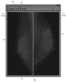
- FIG. 2 is a diagram illustrating an example of an image before the processing according to the present technology is executed.
- the luminance of an image fixedly displayed in a specific area on the screen is not inverted or reduced.
- the image shown in FIG. 2 roughly includes a diagnostic image 11, a frame 14 surrounding the diagnostic image 11, and a menu bar 12 and a tool bar 13 positioned above the diagnostic image 11.
- the image shown in FIG. 2 is often displayed over the entire screen of the display unit 5. That is, the image shown in FIG. 2 is often displayed in the full screen mode. This is because in diagnostic imaging (interpretation), it is necessary to display the diagnostic image 11 as large as possible.
- the X-ray image 11a of one of the left and right breasts is displayed in the left area on the screen, and the X-ray image 11b of the other breast is displayed in the right area.
- An example of the case is shown.
- An X-ray image 11 shown as an example in FIG. 2 is an image when the breast is imaged from the side. The doctor detects breast cancer early by visually recognizing (interpreting) these two X-ray images 11 of the breast. Such a diagnosis is generally called a mammographic diagnosis.
- X-ray image 11 of the breast is displayed on the screen
- X-ray images and CT images of other body parts may be displayed on the screen.
- the line 15 indicating the boundary is displayed in the vertical direction at the boundary between the X-ray image 11a displayed on the left side and the X-ray image 11b displayed on the right side.
- the line 15 is white (that is, the luminance is high).
- FIG. 2 an example in which the region displaying the X-ray image 11 is divided into two parts on the left and right is shown, but the region displaying the X-ray image 11 is divided into four parts on the top, bottom, left and right. In some cases.
- a line image 11 is displayed on the screen.
- a vertical line 15 indicating the boundary of the X-ray image 11 and a horizontal line are displayed on the screen.
- the X-ray image 11 may be displayed on the screen with the number of divisions of 6 divisions, 8 divisions, or more. In this case, the vertical line 15 or the horizontal direction line is selected according to the division number. Is increased.
- the image of the frame 14 surrounding the two X-ray images 11 is displayed on the screen.
- the frame 14 is white (that is, the luminance is high).
- images of the menu bar 12 and the tool bar 13 are displayed above the two X-ray images 11.
- FIG. 3 is an enlarged view showing the menu bar 12 and the tool bar 13.
- the menu bar 12 is white-based, and characters such as “file”, “edit”, and “display” are displayed in black with respect to the white base.
- the toolbar 13 is also white-based, and characters such as “open”, “close”, “fully closed”, etc. are displayed in black with respect to the white base, and the above characters are displayed in black. A figure that reminds you of it is displayed.
- a black line is displayed between the menu bar 12 and the tool bar 13 or in the tool bar 13.
- the image shown in FIG. 2 is often displayed in the full screen mode due to its nature.
- the diagnostic image 11 such as an X-ray image is switched each time the doctor's diagnosis is completed, but the menu bar 12, the tool bar 13, the frame 14, and the line 15 separating the diagnostic image 11 are Displayed at the same position on the screen for a long time.
- each light emitting element constituting an EL display has a characteristic that it deteriorates with time, if the same image is displayed at the same position for a long time, a so-called “burn-in” phenomenon occurs.
- the light emitting elements corresponding to the white base portion continue to emit light with relatively high luminance, and thus the deterioration speed is high.
- light-emitting elements corresponding to characters such as characters displayed in black, graphics, and black lines continue to emit light at relatively low luminance or have a slow deterioration rate. The burn-in occurs due to the variation in deterioration.
- the light emitting elements corresponding to the white base portion of the menu bar 12 and the tool bar 13, the white frame portion 14, and the white line 15 portion that separates the diagnostic image 11 continue to emit light with relatively high luminance, and thus deteriorate. Progression speed is fast.
- the diagnostic image 11 is sequentially switched, the entire image is basically a dark image. Therefore, the light emitting element corresponding to the diagnostic image 11 has a slow deterioration rate. Accordingly, burn-in occurs due to the variation in deterioration (particularly, the boundary between the white frame 14, the white line 15, and the diagnostic image).
- the image display control device 9 image display system 10) according to the present embodiment, by inverting the luminance of the image fixedly displayed on the screen or reducing the luminance, Execute processing to reduce uneven color.
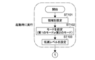
- the control unit 1 executes a process for switching between the first mode and the second mode by executing the processes shown in FIGS. 4 and 5.
- the first mode is a mode for reducing the luminance of the image without inverting the luminance of the image fixedly displayed in a specific area on the screen.
- the second mode is a mode for inverting the luminance of the image and reducing the luminance of the inverted image.
- FIG. 6 is a diagram illustrating an example of an image displayed on the screen when the first mode is executed.
- FIG. 7 is an enlarged view of the menu bar 12 and the tool bar 13 in the first mode.
- FIG. 8 is a diagram illustrating an example of an image displayed on the screen when the second mode is executed.
- FIG. 9 is an enlarged view of the menu bar 12 and the tool bar 13 in the second mode.
- the images shown in FIGS. 6 and 8 include a diagnostic image 11, a frame 14 surrounding the diagnostic image 11, and a menu bar 12 and a tool bar 13 positioned above the diagnostic image 11.
- the images that are fixedly displayed on the screen are a menu bar 12 and a toolbar 13 that are located above the diagnostic image 11, and a frame 14 that surrounds the diagnostic image 11. , And a line 15 that divides the diagnostic image 11.
- control unit 1 inverts the luminance or reduces the luminance in the area on the screen.
- An area is set (step 101).
- the area where the luminance is inverted or the luminance is reduced is an area on the screen where the same image is fixedly displayed.
- the area There are two methods for setting the area.
- the first method first, as a preparatory work, an operator manually inputs an area on the screen where the same image is fixedly displayed, and this area is stored in the storage unit 2 in advance.
- the operator has a frame 14 that surrounds the diagnostic image 11, a menu bar 12 and a toolbar 13, and a line 15 that separates the diagnostic image 11.
- the displayed position is designated via the input unit 3. If there are a plurality of lines 15 that divide the diagnostic image 11, the plurality of lines 15 are designated.
- control part 1 sets the area
- control unit 1 automatically determines the area on the screen where the same image is fixedly displayed when the image display control device 9 (image display system 10) is activated, thereby reducing the luminance. Or a region where the luminance is inverted.
- control unit 1 performs, for example, image analysis of the entire image on a screen as shown in FIG. 2, so that the frame 14 surrounding the diagnostic image 11, the menu bar 12 and the toolbar 13, and the diagnosis What is necessary is just to determine automatically the position where the one or more line 15 which divides
- control unit 1 determines which one of the first mode and the second mode is to be executed, and sets the mode (step 102). Details of how the control unit 1 determines which mode to execute will be described later.
- Which mode is executed is determined by the control unit 1 when the image display control device 9 (image display system 10) is activated, and the determined mode is continuously executed until the next activation. That is, the timing for switching between the first mode and the second mode is one of the timings when the image display control device 9 (image display system 10) is activated, and the image display control device 9 (image display system 10) After startup, the first mode and the second mode cannot be switched.
- the first mode and the second mode can be switched at an appropriate timing that does not give the user (doctor) a sense of incongruity.
- the first mode and the second mode can be switched after the image display control device 9 (image display system 10) is activated.
- the control unit 1 When the control unit 1 sets the mode, the control unit 1 next reads the reduction level stored in the storage unit 2 and sets the reduction level (step 103).
- the reduction level is a value indicating how much the luminance level is reduced in an area on the screen where the same image is fixedly displayed.
- the reduction level is stored in advance in the storage unit 2 by, for example, input through the input unit 3.
- the reduction level is determined in consideration of visibility by the user (doctor). This reduction level may be changeable via the input unit 3.
- FIGS. 6 and 7 and FIGS. 8 and 9 are examples of cases where the first reduction level and the second reduction level have the same value.
- control unit 1 inputs image data for one pixel, for example, for an image as shown in FIG. 2 (step 104).
- the control unit 1 determines whether or not the pixel is a pixel in the region set in Step 101 (Step 105). That is, the control unit 1 determines whether the pixel is a pixel in an area on the screen where the same image is fixedly displayed.
- Step 106 the control unit 1 determines whether or not the current mode is the first mode.
- step 106 the control unit 1 executes a process for reducing the luminance of the pixel without inverting the luminance (step 108).
- step 108 the control unit 1 executes processing for reducing the luminance of the pixel according to the reduction level set in step 103.
- Processing to reduce the brightness is expressed by the following formula (1).
- LVdwn-out represents the level of luminance when the luminance is reduced and output. Further, LVdwn-in represents a luminance input value that should be reduced in luminance.
- the control unit 1 proceeds to the next step 109 when the luminance is reduced without inverting the luminance.
- step 106 when the current mode is not the first mode (NO in step 106), that is, when the current mode is the second mode, the control unit 1 inverts the luminance of the pixel (step 107). ).
- LVrvs-out maximum level of brightness-LVrvs-in (2)
- LVrvs-out represents the level of luminance when the luminance is inverted and output.
- the maximum luminance level is 255 in the case of 256 gradations.
- LVrvs-in represents an input value of luminance that should be inverted.
- control unit 1 When the luminance of the pixel is inverted, the control unit 1 then reduces the luminance of the pixel using the above equation (1) (step 108).
- control unit 1 proceeds to the next step 109.
- step 105 when the pixel is not a pixel in an area on the screen where the same image is fixedly displayed (NO in step 105), the control unit 1 inverts the luminance or reduces the luminance.
- the process proceeds to the next step 109 without executing the process. For example, it is determined that the pixel corresponding to the position where the diagnostic image 11 is displayed is not within the region, and the process of inverting the brightness or reducing the brightness is not executed.
- step 109 the control unit 1 counts the deterioration coefficient for each pixel.
- the deterioration coefficient is a value that takes a higher value as the luminance is higher.
- the control unit 1 displays the first part in the region displayed with relatively high luminance in the first mode and displayed with relatively low luminance in the second mode.
- the first deterioration degree is measured.
- the control unit 1 displays the second degree of deterioration of the second portion in the region that is displayed with relatively low luminance in the first mode and displayed with relatively high luminance in the second mode. And measure.
- the first part is the base part of the menu bar 12 and the tool bar 13, the part of the frame 14, and the part of the line 15 that divides the diagnostic image 11.
- the second portion is a portion of characters, figures, lines, etc. in the menu bar 12 and the tool bar 13.
- FIG. 10 shows the relationship between the image display time, the first deterioration degree for the first portion, and the second deterioration degree for the second portion.
- the first deterioration degree is represented by a one-point difference line of a thin line
- the second deterioration degree is represented by a one-dot chain line of a thick line.
- the control unit 1 measures the first deterioration degree and the second deterioration degree as shown in FIG. 10 by counting the deterioration coefficients.
- the deterioration coefficient corresponds to the slope of a straight line indicating the first deterioration degree and the second deterioration degree.
- the measured first deterioration degree and second deterioration degree are used when the control unit 1 determines which of the first mode and the second mode to execute.
- the degree of deterioration is not limited to the degree of deterioration of pixels (light emitting elements) corresponding to the area on the screen where the same image is fixedly displayed, but also to other areas (area where the diagnostic image 11 is displayed).
- the degree of deterioration of the corresponding pixel (light emitting element) is also measured (see NO at step 105 ⁇ step 109).
- the degree of deterioration, the first degree of deterioration, and the second degree of deterioration are used when the control unit 1 performs luminance correction.
- the degree of deterioration is measured (counted) for each refresh rate, and the measured degree of deterioration is stored in the storage unit 2.
- the control unit 1 When the deterioration coefficient is counted, the control unit 1 next outputs the image data for one pixel (step 110). Next, the control unit 1 determines whether or not the processing from step 104 to step 110 has been completed for all the pixels included in one piece of image data (step 111). When pixels that have not been processed remain (NO in step 111), the control unit 1 advances the step to the next pixel (step 112), and executes the processes of steps 104 to 110 for the next pixel. .
- step 111 When the processing from step 104 to step 110 is completed for all pixels included in one piece of image data (YES in step 111), the control unit 1 advances the step to the next image data (step 113). Then, the control unit 1 repeats the processing from step 104 to step 111 for the next image data.
- an image as shown in FIG. 6 is displayed on the screen in the first mode.
- an image as shown in FIG. 8 is displayed on the screen.
- the luminance of the pixel (light emitting element) corresponding to the area on the screen where the same image is fixedly displayed is displayed. Has been reduced.
- the luminance is not inverted with respect to the original image data shown in FIG.
- the luminance of the base portion of the menu bar 12 and the tool bar 13, the portion of the frame 14, and the portion of the line 15 that delimits the diagnostic image 11 is reduced and changed to gray.
- the luminance of characters, figures, lines, etc. in the menu bar 12 and the tool bar 13 is somewhat reduced, but these are originally dark portions in the original image data in FIG. It is not possible to do.
- the luminance in the original image data is zero, there is no change.
- the luminance of the pixel (light emitting element) corresponding to the area on the screen where the same image is fixedly displayed is displayed. Inverted and the inverted brightness is reduced.
- the luminance of the base portion of the menu bar 12 and the toolbar 13, the portion of the frame 14, and the portion of the line 15 that delimits the diagnostic image 11 is inverted and reduced, and is changed to black.
- the luminance of characters, figures, lines, and the like in the menu bar 12 and the toolbar 13 is inverted and reduced, and is changed to gray.
- FIG. 11 is a flowchart showing processing when determining which mode to execute. In the description of FIG. 11, FIG. 10 is also referred to.
- FIG. 10 shows the transition of the first deterioration level (refer to the dashed line in the thin line) and the second deterioration level (refer to the dashed line in the thick line) when the mode is switched by the process shown in FIG. ing.
- the average of the first deterioration degree and the second deterioration degree is shown by a solid line.
- the first degree of deterioration is, for example, for pixels (light emitting elements) in the base part of the menu bar 12 and the tool bar 13, the part of the frame 14, and the part of the line 15 (first part) that separates the diagnostic image 11.
- Degree of degradation is, for example, the degree of deterioration of a pixel (light emitting element) in a portion (second portion) such as a character, a figure, or a line in the menu bar 12 and the toolbar 13.
- the control unit 1 determines whether or not this activation is the first activation after the program according to the present technology is installed (step 201). In the case of the first activation, the control unit 1 sets a preset mode among the first mode and the second mode at the activation (step 202). In the description here, it is assumed that the first mode is set at the first activation. In step 202, when the mode is set to the first mode, the control unit 1 ends the process.
- the control unit 1 calculates the difference between the first deterioration degree and the second deterioration degree, and the absolute value of this difference sets the threshold Th. It is determined whether or not it exceeds (step 203).
- This threshold is a parameter that determines a cycle for switching modes. That is, if the threshold is small, the mode switching period is short, while if the threshold is large, the mode switching period is long.
- the cycle in which the mode is switched can be various cycles such as a daily cycle, a week cycle, and a month cycle (for example, when used for 10 hours a day).
- control unit 1 sets the current mode to the same mode as the previous mode. (Step 206).
- Step 204 the control unit 1 determines whether the first deterioration degree and the second deterioration degree are reversed between the previous mode switching and the present time.
- control unit 1 changes the current mode to the previous mode.
- the same mode is set (step 206).
- step 204 if the first deterioration degree and the second deterioration degree are reversed between the previous mode switching and the present time (YES in step 204), the current mode is different from the previous mode.
- the mode is set (step 205). If the mode set for the first time has not yet been switched to another mode, if the result of step 203 is affirmative, the control unit 1 does not execute the process of step 204 but performs step 205. Proceed to Then, the control unit 1 switches the mode set for the first time to another mode.
- the first mode is set at the first startup. Therefore, after the first activation, an image as shown in FIG. 6 is displayed on the screen. While the image is displayed on the screen, the first deterioration degree and the second deterioration degree are measured by the process as shown in FIG.
- the absolute value of the difference between the first deterioration degree and the second deterioration degree does not exceed the threshold Th at the second and third start-up times. Therefore, the same mode as the previous mode (first mode) is set at the second and third activations.
- the mode set for the first time has not yet been switched to another mode, and the absolute value of the difference between the first deterioration degree and the second deterioration degree is the threshold Th. Since it exceeds, the first mode set for the first time is switched to the second mode. Therefore, after the fourth activation, an image as shown in FIG. 8 is displayed on the screen. Since the luminance is inverted between the first mode and the second mode, the slopes of the first deterioration degree and the second deterioration degree are reversed.
- the absolute value of the difference between the first degradation level and the second degradation level does not exceed the threshold Th during the fifth to seventh activations.
- the first deterioration degree and the second deterioration degree are not reversed between the previous mode switching and the present time. Accordingly, at the time of the fifth to seventh activation, the previous mode is referred to and the second mode that is the same as the previous mode is set.
- the previous mode is referred to, and the second mode that is the same as the previous mode is set.
- the absolute value of the difference between the first deterioration degree and the second deterioration degree exceeds the threshold Th. Further, at the time of the tenth activation, the first deterioration degree and the second deterioration degree are reversed between the previous mode switching and the present time. Accordingly, at the time of the tenth activation, the previous mode is switched and the first mode is set.
- the luminance of an image fixedly displayed in a specific area on the screen is inverted.
- the part displayed with relatively high brightness and the part displayed with relatively low brightness can be reversed in the first mode and the second mode. Therefore, since the progress speed of the deterioration of the light emitting element in the region where the image is fixedly displayed can be made uniform (see FIG. 9), for example, problems due to burn-in and color unevenness can be alleviated. .
- the luminance of an image fixedly displayed in a specific area on the screen is reduced in both the first mode and the second mode.
- the luminance of an image fixedly displayed in a specific area on the screen is reduced, the progress rate of deterioration of the light emitting element can be reduced.
- the brightness of images displayed around the diagnostic image 11 such as the menu bar 12, the toolbar 13, and the frame 14 is reduced.
- the brightness of the image located around the diagnostic image 11 is reduced, there is also an effect that the diagnostic image 11 is easy to see. This will be described below.
- FIG. 12 is a diagram for explaining the reason why the diagnostic image 11 is easy to see.
- a black circle surrounded by a high-luminance portion is shown.
- the five gray circles existing inside the black circle are very difficult to distinguish. This is because the pupil needs to be opened in order to distinguish the difference in the low luminance region, whereas the pupil is opened by the high luminance part existing around the black circle.
- the upper drawing in FIG. 12 corresponds to the image shown in FIG.
- the lower drawing of FIG. 12 corresponds to the images shown in FIGS. That is, in this embodiment, since the brightness of images around the diagnostic image such as the menu bar 12, the toolbar 13, and the frame 14 is reduced, when the user (doctor) performs image diagnosis, It is easy to distinguish the difference in the low luminance area in the image. This leads to an improvement in diagnosis accuracy.
- the number of the display units 5 is two or more.
- the visibility may be deteriorated.
- the image shown in FIG. 6 is displayed on a specific display unit 5, and if the image shown in FIG. 8 is displayed on another display unit 5, the visibility may deteriorate.
- control unit 1 controls the first mode and the second mode in the two or more display units 5 so that the modes executed in the two or more display units 5 are the same mode.
- the process for switching between the modes is executed.
- FIG. 13 is a flowchart showing processing executed by the image display control device 9 (image display system 10) according to the second embodiment.
- control unit 1 determines the number of display units 5 (step 301).
- the number of display units 5 may be two, three, or more.
- control unit 1 sets, for each display unit 5, a region where the luminance is reversed or the luminance is reduced (that is, a region where the same image is fixedly displayed on the screen) (Step S 1). 302).
- the method for setting this area is the same as that in the first embodiment. Note that different images may be displayed on each display unit 5. Therefore, the area may be different in each display unit 5.
- control unit 1 determines which of the first mode and the second mode is to be executed, and sets the mode (step 303).
- the mode set in each display unit 5 is common. Thereby, visibility when a user (doctor) monitors two or more display parts 5 can be improved.
- step 303 the control unit 1 determines the display unit 5 having the maximum deterioration level, and adjusts the switching of the mode on the display unit 5 having the maximum deterioration level.
- the mode may be switched.
- the control unit 1 measures the degree of deterioration of pixels (light emitting elements) in an area where the same image is fixedly displayed on the screen for each of the two or more display units 5.
- a deterioration degree here, the average value of the 1st deterioration degree shown in FIG. 10 and the 2nd deterioration degree is used, for example.
- the control part 1 determines the display part 5 with the largest degradation degree based on each measured degradation degree.
- control unit 1 switches the mode of the other display unit 5 so as to match the switching of the mode on the display unit 5 having the maximum deterioration degree.
- the mode switching method in the display unit 5 having the maximum degree of deterioration is the same as that in the first embodiment (see FIGS. 10 and 11).
- the mode switching cycle is basically constant even if the mode is switched according to the mode switching of the display unit 5 having the maximum deterioration degree. Therefore, it is possible to switch the mode appropriately without problems of image sticking and color unevenness.
- the control unit 1 sets the reduction level so that the luminance reduction level in each mode executed by the two or more display units 5 becomes the same level. Thereby, since the reduction level (that is, brightness) of the brightness in the two or more display units 5 is common, the visibility when the user (doctor) monitors the two or more display units 5 can be improved. it can.
- the luminance reduction level in the other display units 5 may be set so as to match the luminance reduction level in the display unit 5 having the maximum degree of deterioration.
- control unit 1 executes the processing shown in FIG.
- the first mode and the second mode are switched based on the first deterioration degree and the second deterioration degree.
- the first mode and the second mode are changed based on time. Processing for switching to the mode may be executed. In this case, when the time during which an image is displayed on the screen reaches a predetermined time, one mode is switched to the other mode.
- the first reduction level in the first mode is the same as the second reduction level in the second mode has been described, but the first reduction level and the second reduction level are May be different.
- the first reduction level and the second reduction level are May be different.
- black characters and figures are displayed on a gray base as shown in FIG. 7
- gray letters and figures are displayed on a black base as shown in FIG. The visibility is better than that. Therefore, it is conceivable to make the first reduction level larger than the second reduction level.
- This technique can also take the following composition.
- An image display comprising: a control unit that switches between a second mode for reducing the brightness of the image and controls display so that the image is displayed in the region on the screen according to the switched mode. Control device.
- a second degree of degradation for a second portion in the region that is displayed at a relatively low brightness in the first mode and is displayed at a relatively high brightness in the second mode is displayed at a relatively high brightness in the second mode.
- An image display control device that switches between the first mode and the second mode based on the measured first degradation level and the second degradation level. (3) The image display control device according to (2) above, The control unit calculates a difference between the first deterioration degree and the second deterioration degree, and when the difference exceeds a predetermined threshold, the control unit sets the first mode and the second mode. An image display control device that can be switched.
- the image display control device is an image display control apparatus which measures the said 1st degradation degree and the said 2nd degradation degree based on the degradation coefficient which is a value which takes a high value, so that brightness
- the image display control device according to any one of (1) to (4), The control unit determines which one of the first mode and the second mode is to be executed when the image display control device is activated, thereby allowing the first mode and the second mode to be executed.
- the image display control device that switches the mode.
- the image display control device is an image display control apparatus which performs the mode determined at the time of starting of the said image display control apparatus continuously until the next starting time.
- the image display control device according to any one of (1) to (6), The image display control apparatus, wherein the control unit displays a diagnostic image in an area other than an area where the image is fixedly displayed.
- the image display control device according to (7) above, The image display control apparatus, wherein an image that is fixedly displayed in a specific area on the screen and has reduced luminance is displayed in an area around the diagnostic image.
- the image display control device according to any one of claims (1) to (8), The control unit is fixed to a specific area on the screen where the luminance is inverted between the first mode and the second mode by analyzing an image displayed on the screen as a whole.
- An image display control apparatus for determining an area of an image displayed on the screen.
- the image display control device switches between the first mode and the second mode on the plurality of screens so that each mode executed on the plurality of screens is the same mode. .
- (11) The image display control device according to (10) above, The control unit measures the degree of deterioration in the region in each of the plurality of screens, determines a screen having the maximum degree of deterioration based on each measured degree of deterioration, and the degree of deterioration is the maximum. An image display control device that switches the mode of another screen to match the switching of the mode on one screen.
- the image display control device according to (10) or (11) above, The image display control apparatus, wherein the control unit sets a reduction level so that a reduction level of brightness in each mode executed on the plurality of screens is the same level.
- a display unit A first mode for reducing the luminance of the image without inverting the luminance of the image fixedly displayed in the specific area of the display unit; and the luminance of the image is inverted,
- An image display system comprising: a control unit that switches between a second mode for reducing luminance.
- the image display system according to (13) above, The display section is plural, The image display system in which the control unit switches the first mode and the second mode in the plurality of display units, respectively, so that the modes executed in the plurality of display units become the same mode.
Landscapes
- Engineering & Computer Science (AREA)
- Theoretical Computer Science (AREA)
- Physics & Mathematics (AREA)
- General Physics & Mathematics (AREA)
- Computer Hardware Design (AREA)
- Human Computer Interaction (AREA)
- General Engineering & Computer Science (AREA)
- Control Of Indicators Other Than Cathode Ray Tubes (AREA)
- Controls And Circuits For Display Device (AREA)
- Electroluminescent Light Sources (AREA)
- Transforming Electric Information Into Light Information (AREA)
- Control Of El Displays (AREA)
Abstract
Description
前記制御部は、前記画面上の特定の領域に固定的に表示される画像の輝度を反転せずに、前記画像の輝度を低減する第1のモードと、前記画像の輝度を反転し、反転された前記画像の輝度を低減する第2のモードとを切り換え、かつ、切り換えられたモードに応じて、前記画面上の前記領域に前記画像を表示させるように表示を制御する。
前記制御部は、前記表示部の特定の領域に固定的に表示される画像の輝度を反転せずに、前記画像の輝度を低減する第1のモードと、前記画像の輝度を反転し、反転された前記画像の輝度を低減する第2のモードとを切り換える。
切り換えられたモードに応じて、前記画面上の前記領域に前記画像を表示させるように表示が制御される。
切り換えられたモードに応じて、前記画面上の前記領域に前記画像を表示させるように表示を制御するステップと
を実行させる。
以下、本技術に係る実施形態を、図面を参照しながら説明する。
図1は、本技術に係る画像表示システム10を示す図である。図1に示すように、本技術に係る画像表示システム10は、画像表示制御装置9と、表示装置5(表示部5)とを備えている。画像表示制御装置9は、制御部1と、記憶部2と、入力部3と、通信部4と有する。
図2は、本技術に係る処理が実行される前の画像の一例を示す図である。図2に示される画像は、画面上の特定の領域に固定的に表示される画像の輝度が反転されてもいないし低減されてもいない。
次に、本実施形態に係る画像表示制御装置9(画像表示システム10)の処理について説明する。図4及び図5は、本実施形態に係る画像表示制御装置9の処理を示すフローチャートである。
次に、制御部1が、起動時において、第1のモード及び第2のモードのうち、どちらのモードを実行するかを決定するときの処理について説明する。
以上説明したように、本実施形態では、第1のモードと第2のモードとでは、画面上の特定の領域に固定的に表示される画像の輝度が反転される。これにより、相対的に高い輝度で表示される部分と、相対的に低い輝度で表示される部分とを第1のモード及び第2のモードで反転することができる。従って、画像が固定的に表示される領域内における発光素子の劣化の進行速度を均一化することができるため(図9参照)、例えば、焼きつきや、色むらによる問題を緩和することができる。
次に、本技術の第2実施形態について説明する。なお、第2実施形態の説明では、上述の第1実施形態と同様の構成及び機能を有する部分については、同一符号を付し、説明を省略又は簡略化する。
(1) 前記画面上の特定の領域に固定的に表示される画像の輝度を反転せずに、前記画像の輝度を低減する第1のモードと、前記画像の輝度を反転し、反転された前記画像の輝度を低減する第2のモードとを切り換え、かつ、切り換えられたモードに応じて、前記画面上の前記領域に前記画像を表示させるように表示を制御する制御部
を具備する画像表示制御装置。
(2) 上記(1)に記載の画像表示制御装置であって、
前記制御部は、前記第1のモードにおいて相対的に高い輝度で表示され、前記第2のモードにおいて相対的に低い輝度で表示される、前記領域内の第1の部分についての第1の劣化度と、前記第1のモードにおいて相対的に低い輝度で表示され、前記第2のモードにおいて相対的に高い輝度で表示される、前記領域内の第2の部分についての第2の劣化度とを測定し、測定された前記第1の劣化度及び前記第2の劣化度に基づいて、前記第1のモード及び前記第2のモードを切り換える
画像表示制御装置。
(3) 上記(2)に記載の画像表示制御装置であって、
前記制御部は、前記第1の劣化度と、前記第2の劣化度との差を算出し、前記差が所定の閾値を超えたときに、前記第1のモード及び前記第2のモードを切り換え可能な状態とする
画像表示制御装置。
(4) 上記(2)又は(3)に記載の画像表示制御装置であって、
前記制御部は、輝度が高いほど高い値を取る値である劣化係数に基づいて前記第1の劣化度及び前記第2の劣化度を測定する
画像表示制御装置。
(5) 上記(1)乃至(4)のうちいずれか1つに記載の画像表示制御装置であって、
前記制御部は、前記画像表示制御装置の起動時に、前記第1のモード及び前記第2のモードのうち、どちらのモードを実行するかを決定することによって、前記第1のモード及び前記第2のモードを切り換える
画像表示制御装置。
(6) 上記(5)に記載の画像表示制御装置であって、
前記制御部は、前記画像表示制御装置の起動時において決定されたモードを、次の起動時まで継続して実行する
画像表示制御装置。
(7) 上記(1)乃至(6)のうち何れか1つに記載の画像表示制御装置であって、
前記制御部は、前記画像が固定的に表示される領域以外の領域に診断用の画像を表示させる
画像表示制御装置。
(8) 上記(7)に記載の画像表示制御装置であって、
前記画面上の特定の領域に固定的に表示される、輝度が低減される画像は、前記診断用の画像の周囲の領域に表示される
画像表示制御装置。
(9) 請求項(1)乃至(8)のうち何れか1つに記載の画像表示制御装置であって、
前記制御部は、前記画面上に全体的に表示される画像を解析することによって、第1のモードと、第2のモードとで輝度が反転される、前記画面上の特定の領域に固定的に表示される画像の領域を判定する
画像表示制御装置。
(10) 上記(1)乃至(9)のうちいずれか1つに記載の画像表示制御装置であって、
前記制御部は、複数の前記画面上で実行される各モードが同じモードとなるように、前記複数の画面上において、それぞれ、前記第1のモードと第2のモードとを切り換える
画像表示制御装置。
(11) 上記(10)に記載の画像表示制御装置であって、
前記制御部は、前記複数の画面において、それぞれ、前記領域における劣化度を測定し、測定された各劣化度に基づいて、前記劣化度が最大である画面を判定し、前記劣化度が最大である画面でのモードの切り換えに合わせるように、他の画面のモードを切り換える
画像表示制御装置。
(12) 上記(10)又は(11)に記載の画像表示制御装置であって、
前記制御部は、前記複数の画面上で実行される各モードでの輝度の低減のレベルが同じレベルとなるように、低減レベルを設定する
画像表示制御装置。
(13) 表示部と、
前記表示部の特定の領域に固定的に表示される画像の輝度を反転せずに、前記画像の輝度を低減する第1のモードと、前記画像の輝度を反転し、反転された前記画像の輝度を低減する第2のモードとを切り換える制御部と
を具備する画像表示システム。
(14) 上記(13)に記載の画像表示システムであって、
前記表示部は、複数であり、
前記制御部は、複数の表示部で実行される各モードが同じモードとなるように、前記複数の表示部において、それぞれ、前記第1のモードと前記第2のモードとを切り換える
画像表示システム。
(15) 画面上の特定の領域に固定的に表示される画像の輝度を反転せずに、前記画像の輝度を低減する第1のモードと、前記画像の輝度を反転し、反転された前記画像の輝度を低減する第2のモードとを切り換え、
切り換えられたモードに応じて、前記画面上の前記領域に前記画像を表示させるように表示を制御する
画像表示制御方法。
(14) 画像表示制御装置に、
画面上の特定の領域に固定的に表示される画像の輝度を反転せずに、前記画像の輝度を低減する第1のモードと、前記画像の輝度を反転し、反転された前記画像の輝度を低減する第2のモードとを切り換えるステップと、
切り換えられたモードに応じて、前記画面上の前記領域に前記画像を表示させるように表示を制御するステップと
を実行させるプログラム。
2…記憶部
3…入力部
4…通信部
5…表示部
9…画像表示制御装置
10…画像表示システム
11…診断用画像(X線画像)
12…メニューバー
13…ツールバー
14…枠
15…ライン
Claims (16)
- 画面上の特定の領域に固定的に表示される画像の輝度を反転せずに、前記画像の輝度を低減する第1のモードと、前記画像の輝度を反転し、反転された前記画像の輝度を低減する第2のモードとを切り換え、かつ、切り換えられたモードに応じて、前記画面上の前記領域に前記画像を表示させるように表示を制御する制御部
を具備する画像表示制御装置。 - 請求項1に記載の画像表示制御装置であって、
前記制御部は、前記第1のモードにおいて相対的に高い輝度で表示され、前記第2のモードにおいて相対的に低い輝度で表示される、前記領域内の第1の部分についての第1の劣化度と、前記第1のモードにおいて相対的に低い輝度で表示され、前記第2のモードにおいて相対的に高い輝度で表示される、前記領域内の第2の部分についての第2の劣化度とを測定し、測定された前記第1の劣化度及び前記第2の劣化度に基づいて、前記第1のモード及び前記第2のモードを切り換える
画像表示制御装置。 - 請求項2に記載の画像表示制御装置であって、
前記制御部は、前記第1の劣化度と、前記第2の劣化度との差を算出し、前記差が所定の閾値を超えたときに、前記第1のモード及び前記第2のモードを切り換え可能な状態とする
画像表示制御装置。 - 請求項2に記載の画像表示制御装置であって、
前記制御部は、輝度が高いほど高い値を取る値である劣化係数に基づいて前記第1の劣化度及び前記第2の劣化度を測定する
画像表示制御装置。 - 請求項1に記載の画像表示制御装置であって、
前記制御部は、前記画像表示制御装置の起動時に、前記第1のモード及び前記第2のモードのうち、どちらのモードを実行するかを決定することによって、前記第1のモード及び前記第2のモードを切り換える
画像表示制御装置。 - 請求項5に記載の画像表示制御装置であって、
前記制御部は、前記画像表示制御装置の起動時において決定されたモードを、次の起動時まで継続して実行する
画像表示制御装置。 - 請求項1に記載の画像表示制御装置であって、
前記制御部は、前記画像が固定的に表示される領域以外の領域に診断用の画像を表示させる
画像表示制御装置。 - 請求項7に記載の画像表示制御装置であって、
前記制御部は、前記画面上の特定の領域に固定的に表示される、輝度が低減される画像を、前記診断用の画像の周囲の領域に表示させる
画像表示制御装置。 - 請求項1に記載の画像表示制御装置であって、
前記制御部は、前記画面上に全体的に表示される画像を解析することによって、第1のモードと、第2のモードとで輝度が反転される、前記画面上の特定の領域に固定的に表示される画像の領域を判定する
画像表示制御装置。 - 請求項1に記載の画像表示制御装置であって、
前記制御部は、複数の前記画面上で実行される各モードが同じモードとなるように、前記複数の画面上において、それぞれ、前記第1のモードと前記第2のモードとを切り換える
画像表示制御装置。 - 請求項10に記載の画像表示制御装置であって、
前記制御部は、前記複数の画面において、それぞれ、前記領域における劣化度を測定し、測定された各劣化度に基づいて、前記劣化度が最大である画面を判定し、前記劣化度が最大である画面でのモードの切り換えに合わせるように、他の画面のモードを切り換える
画像表示制御装置。 - 請求項10に記載の画像表示制御装置であって、
前記制御部は、前記複数の画面上で実行される各モードでの輝度の低減のレベルが同じレベルとなるように、低減レベルを設定する
画像表示制御装置。 - 表示部と、
前記表示部の特定の領域に固定的に表示される画像の輝度を反転せずに、前記画像の輝度を低減する第1のモードと、前記画像の輝度を反転し、反転された前記画像の輝度を低減する第2のモードとを切り換える制御部と
を具備する画像表示システム。 - 請求項13に記載の画像表示システムであって、
前記表示部は、複数であり、
前記制御部は、複数の表示部で実行される各モードが同じモードとなるように、前記複数の表示部において、それぞれ、前記第1のモードと前記第2のモードとを切り換える
画像表示システム。 - 画面上の特定の領域に固定的に表示される画像の輝度を反転せずに、前記画像の輝度を低減する第1のモードと、前記画像の輝度を反転し、反転された前記画像の輝度を低減する第2のモードとを切り換え、
切り換えられたモードに応じて、前記画面上の前記領域に前記画像を表示させるように表示を制御する
画像表示制御方法。 - 画像表示制御装置に、
画面上の特定の領域に固定的に表示される画像の輝度を反転せずに、前記画像の輝度を低減する第1のモードと、前記画像の輝度を反転し、反転された前記画像の輝度を低減する第2のモードとを切り換えるステップと、
切り換えられたモードに応じて、前記画面上の前記領域に前記画像を表示させるように表示を制御するステップと
を実行させるプログラム。
Priority Applications (5)
| Application Number | Priority Date | Filing Date | Title |
|---|---|---|---|
| US14/786,294 US9953564B2 (en) | 2013-06-17 | 2014-04-10 | Image display control apparatus, image display system, image display control method and program |
| CN201480033009.0A CN105393297B (zh) | 2013-06-17 | 2014-04-10 | 图像显示控制设备、图像显示系统及控制图像显示的方法 |
| EP14813345.7A EP3012826A4 (en) | 2013-06-17 | 2014-04-10 | Image display control device, image display system, image display control method and program |
| JP2015522484A JPWO2014203438A1 (ja) | 2013-06-17 | 2014-04-10 | 画像表示制御装置、画像表示システム、画像表示制御方法及びプログラム |
| US15/926,600 US20180218672A1 (en) | 2013-06-17 | 2018-03-20 | Image display control apparatus, image display system, image display control method and program |
Applications Claiming Priority (2)
| Application Number | Priority Date | Filing Date | Title |
|---|---|---|---|
| JP2013126982 | 2013-06-17 | ||
| JP2013-126982 | 2013-06-17 |
Related Child Applications (2)
| Application Number | Title | Priority Date | Filing Date |
|---|---|---|---|
| US14/786,294 A-371-Of-International US9953564B2 (en) | 2013-06-17 | 2014-04-10 | Image display control apparatus, image display system, image display control method and program |
| US15/926,600 Continuation US20180218672A1 (en) | 2013-06-17 | 2018-03-20 | Image display control apparatus, image display system, image display control method and program |
Publications (1)
| Publication Number | Publication Date |
|---|---|
| WO2014203438A1 true WO2014203438A1 (ja) | 2014-12-24 |
Family
ID=52104194
Family Applications (1)
| Application Number | Title | Priority Date | Filing Date |
|---|---|---|---|
| PCT/JP2014/002072 Ceased WO2014203438A1 (ja) | 2013-06-17 | 2014-04-10 | 画像表示制御装置、画像表示システム、画像表示制御方法及びプログラム |
Country Status (5)
| Country | Link |
|---|---|
| US (2) | US9953564B2 (ja) |
| EP (1) | EP3012826A4 (ja) |
| JP (1) | JPWO2014203438A1 (ja) |
| CN (1) | CN105393297B (ja) |
| WO (1) | WO2014203438A1 (ja) |
Cited By (2)
| Publication number | Priority date | Publication date | Assignee | Title |
|---|---|---|---|---|
| US11417267B2 (en) | 2018-02-07 | 2022-08-16 | Samsung Electronics Co., Ltd. | Electronic device for controlling display of content on basis of brightness information and operation method therefor |
| US12307561B2 (en) | 2020-03-09 | 2025-05-20 | Fujifilm Corporation | Display control apparatus, display control method, and display control program |
Families Citing this family (6)
| Publication number | Priority date | Publication date | Assignee | Title |
|---|---|---|---|---|
| EP3012826A4 (en) * | 2013-06-17 | 2017-02-15 | Sony Corporation | Image display control device, image display system, image display control method and program |
| KR20150003560A (ko) * | 2013-07-01 | 2015-01-09 | 삼성전자주식회사 | 사용자의 모션 정보에 기초하여 사용자 인터페이스(ui)를 변경시키는 방법 및 장치 |
| CN107086027A (zh) * | 2017-06-23 | 2017-08-22 | 青岛海信移动通信技术股份有限公司 | 文字显示方法及装置、移动终端及存储介质 |
| CN111048056A (zh) * | 2019-12-19 | 2020-04-21 | 惠州Tcl移动通信有限公司 | 终端设备亮度调节方法及其系统、存储介质及终端设备 |
| KR102924566B1 (ko) * | 2021-11-03 | 2026-02-09 | 삼성디스플레이 주식회사 | 표시 장치 |
| WO2023211453A1 (en) * | 2022-04-28 | 2023-11-02 | Hewlett-Packard Development Company, L.P. | Decay rates and luminance values of display panels |
Citations (4)
| Publication number | Priority date | Publication date | Assignee | Title |
|---|---|---|---|---|
| JP2000214838A (ja) * | 1999-01-27 | 2000-08-04 | Fuji Photo Film Co Ltd | 表示装置 |
| JP2002221908A (ja) | 2000-11-21 | 2002-08-09 | Nikken Kogyo Kk | 価格表示器具 |
| JP2003186434A (ja) * | 2001-12-19 | 2003-07-04 | Matsushita Electric Ind Co Ltd | 表示装置及び携帯機器 |
| JP2012123414A (ja) * | 2005-08-12 | 2012-06-28 | Semiconductor Energy Lab Co Ltd | 表示装置 |
Family Cites Families (43)
| Publication number | Priority date | Publication date | Assignee | Title |
|---|---|---|---|---|
| AT347258B (de) * | 1975-01-24 | 1978-12-27 | Eumig | Laufbildkamera |
| JPH06102845A (ja) * | 1992-09-22 | 1994-04-15 | Komatsu Ltd | 画像表示制御装置 |
| US5986662A (en) * | 1996-10-16 | 1999-11-16 | Vital Images, Inc. | Advanced diagnostic viewer employing automated protocol selection for volume-rendered imaging |
| EP1160760B1 (en) * | 1997-01-31 | 2010-11-24 | Hitachi, Ltd. | Image displaying system with capability of modifying a display attribute in a specific display area |
| US6809776B1 (en) * | 1997-04-23 | 2004-10-26 | Thomson Licensing S.A. | Control of video level by region and content of information displayed |
| US6151008A (en) * | 1997-08-01 | 2000-11-21 | Compaq Computer Corporation | Method and apparatus for controlling the brightness of a display screen |
| WO1999053472A1 (en) * | 1998-04-15 | 1999-10-21 | Cambridge Display Technology Ltd. | Display control device with modes for reduced power consumption |
| JP2000221908A (ja) * | 1999-02-03 | 2000-08-11 | Alpine Electronics Inc | 画像表示装置における画像表示方法 |
| US6235455B1 (en) * | 1999-04-26 | 2001-05-22 | Konica Corporation | Silver halide color photographic light sensitive material and image forming method by use thereof |
| US6536907B1 (en) * | 2000-02-08 | 2003-03-25 | Hewlett-Packard Development Company, L.P. | Aberration compensation in image projection displays |
| ITRM20010280A1 (it) * | 2001-05-23 | 2002-11-25 | C N R Consiglio Naz Delle Ri C | Dispositivo scintigrafico modulare ad elevata risoluzione spaziale a piu' fotomoltiplicatori indipendenti e con area di visualizzazione este |
| KR100472359B1 (ko) * | 2001-11-28 | 2005-02-21 | 엘지전자 주식회사 | 평균 휘도 레벨 설정방법 |
| JP2004242143A (ja) * | 2003-02-07 | 2004-08-26 | Fuji Photo Film Co Ltd | マルチディスプレイシステム |
| JP4628770B2 (ja) * | 2004-02-09 | 2011-02-09 | 株式会社日立製作所 | 照明装置を備えた画像表示装置及び画像表示方法 |
| JP2005283908A (ja) * | 2004-03-29 | 2005-10-13 | Sanyo Electric Co Ltd | ディスプレイの焼付き寿命の延命化方法 |
| GB0422347D0 (en) * | 2004-10-08 | 2004-11-10 | Koninkl Philips Electronics Nv | Transflective liquid crystal display device |
| US7614011B2 (en) * | 2004-10-21 | 2009-11-03 | International Business Machines Corporation | Apparatus and method for display power saving |
| WO2006082883A1 (ja) * | 2005-02-03 | 2006-08-10 | Nikon Corporation | 表示装置、電子機器およびカメラ |
| US8208081B2 (en) * | 2006-08-24 | 2012-06-26 | Sharp Kabushiki Kaisha | Liquid crystal display having pixel including multiple subpixels |
| US7924306B2 (en) * | 2006-09-15 | 2011-04-12 | Hewlett-Packard Development Company, L.P. | Videoconferencing with enhanced illusion of physical presence in a common space |
| US8401256B2 (en) * | 2006-11-13 | 2013-03-19 | General Electric Company | Systems and methods for an interactive PACS image display test image |
| US20090046089A1 (en) | 2007-08-16 | 2009-02-19 | Motorola, Inc. | Burn-in compensation for display |
| US8294387B2 (en) * | 2007-09-26 | 2012-10-23 | Sharp Kabushiki Kaisha | Backlight device and display device using the same for adjusting color tone of illumination light |
| WO2009154438A1 (en) * | 2008-06-16 | 2009-12-23 | Optelec Development B.V. | Method and apparatus for automatically magnifying a text based image of an object |
| JP5307503B2 (ja) * | 2008-07-01 | 2013-10-02 | 株式会社日立ハイテクサイエンス | X線分析装置及びx線分析方法 |
| WO2010143100A1 (en) * | 2009-06-10 | 2010-12-16 | Koninklijke Philips Electronics N.V. | Visualization apparatus for visualizing an image data set |
| JP2011169821A (ja) * | 2010-02-19 | 2011-09-01 | Sii Nanotechnology Inc | X線分析装置およびx線分析のマッピング方法 |
| JP2011203659A (ja) * | 2010-03-26 | 2011-10-13 | Sony Corp | 表示装置および電子機器 |
| US8836723B2 (en) * | 2010-06-18 | 2014-09-16 | Vantage Surgical Systems, Inc. | Augmented reality methods and systems including optical merging of a plurality of component optical images |
| US8641206B2 (en) * | 2010-06-22 | 2014-02-04 | Seiko Epson Corporation | Projector having a movable tilted aperture and cut filter |
| EP2443992A2 (en) * | 2010-10-25 | 2012-04-25 | Fujifilm Corporation | Diagnosis support apparatus, diagnosis support method, lesioned part detection apparatus, and lesioned part detection method |
| JP5509173B2 (ja) * | 2011-10-19 | 2014-06-04 | Eizo株式会社 | 表示装置及び表示方法 |
| CN103505240B (zh) * | 2012-06-29 | 2018-05-22 | 通用电气公司 | 超声成像设备和用于自动调整用户界面布局的装置及方法 |
| US9652589B2 (en) * | 2012-12-27 | 2017-05-16 | General Electric Company | Systems and methods for using a touch-sensitive display unit to analyze a medical image |
| US10492062B2 (en) * | 2013-03-28 | 2019-11-26 | Iconic Data Inc. | Protected health information image capture, processing and submission from a mobile device |
| US10482216B2 (en) * | 2013-03-28 | 2019-11-19 | Iconic Data Inc. | Protected health information image capture, processing and submission from a client device |
| US10811123B2 (en) * | 2013-03-28 | 2020-10-20 | David Laborde | Protected health information voice data and / or transcript of voice data capture, processing and submission |
| EP3012826A4 (en) * | 2013-06-17 | 2017-02-15 | Sony Corporation | Image display control device, image display system, image display control method and program |
| JP6198512B2 (ja) * | 2013-08-06 | 2017-09-20 | キヤノン株式会社 | 画像表示装置、その制御方法、及び画像表示システム |
| JP6346036B2 (ja) * | 2014-09-09 | 2018-06-20 | 株式会社日立ハイテクサイエンス | 蛍光x線分析装置及びその測定位置調整方法 |
| US9933926B2 (en) * | 2015-09-25 | 2018-04-03 | Synaptive Medical (Barbados) Inc. | Method and system for medical data display |
| US10383583B2 (en) * | 2015-10-16 | 2019-08-20 | Canon Medical Systems Corporation | X-ray CT apparatus |
| US20170173262A1 (en) * | 2017-03-01 | 2017-06-22 | François Paul VELTZ | Medical systems, devices and methods |
-
2014
- 2014-04-10 EP EP14813345.7A patent/EP3012826A4/en not_active Ceased
- 2014-04-10 CN CN201480033009.0A patent/CN105393297B/zh not_active Expired - Fee Related
- 2014-04-10 US US14/786,294 patent/US9953564B2/en active Active
- 2014-04-10 JP JP2015522484A patent/JPWO2014203438A1/ja active Pending
- 2014-04-10 WO PCT/JP2014/002072 patent/WO2014203438A1/ja not_active Ceased
-
2018
- 2018-03-20 US US15/926,600 patent/US20180218672A1/en not_active Abandoned
Patent Citations (4)
| Publication number | Priority date | Publication date | Assignee | Title |
|---|---|---|---|---|
| JP2000214838A (ja) * | 1999-01-27 | 2000-08-04 | Fuji Photo Film Co Ltd | 表示装置 |
| JP2002221908A (ja) | 2000-11-21 | 2002-08-09 | Nikken Kogyo Kk | 価格表示器具 |
| JP2003186434A (ja) * | 2001-12-19 | 2003-07-04 | Matsushita Electric Ind Co Ltd | 表示装置及び携帯機器 |
| JP2012123414A (ja) * | 2005-08-12 | 2012-06-28 | Semiconductor Energy Lab Co Ltd | 表示装置 |
Non-Patent Citations (1)
| Title |
|---|
| See also references of EP3012826A4 * |
Cited By (2)
| Publication number | Priority date | Publication date | Assignee | Title |
|---|---|---|---|---|
| US11417267B2 (en) | 2018-02-07 | 2022-08-16 | Samsung Electronics Co., Ltd. | Electronic device for controlling display of content on basis of brightness information and operation method therefor |
| US12307561B2 (en) | 2020-03-09 | 2025-05-20 | Fujifilm Corporation | Display control apparatus, display control method, and display control program |
Also Published As
| Publication number | Publication date |
|---|---|
| JPWO2014203438A1 (ja) | 2017-02-23 |
| EP3012826A4 (en) | 2017-02-15 |
| CN105393297B (zh) | 2018-08-10 |
| EP3012826A1 (en) | 2016-04-27 |
| CN105393297A (zh) | 2016-03-09 |
| US9953564B2 (en) | 2018-04-24 |
| US20180218672A1 (en) | 2018-08-02 |
| US20160063917A1 (en) | 2016-03-03 |
Similar Documents
| Publication | Publication Date | Title |
|---|---|---|
| WO2014203438A1 (ja) | 画像表示制御装置、画像表示システム、画像表示制御方法及びプログラム | |
| US9990722B2 (en) | Electronic device providing a bioeffect image | |
| US9336576B2 (en) | Method and system for improving the visibility of features of an image | |
| EP3113168A1 (en) | Devices and methods for reducing artefacts in display devices by the use of overdrive | |
| CN101923827B (zh) | 自发光显示设备及其功耗降低方法 | |
| JP2021536031A (ja) | ディスプレイの再スキャン | |
| US10212312B2 (en) | Image colour calibration with multiple colour scales | |
| JP5337310B2 (ja) | 画像処理装置、表示装置および画像処理方法 | |
| CN108573678B (zh) | 一种显示方法及装置 | |
| US12468386B2 (en) | Intra-frame pause and delayed emission timing for foveated displays | |
| RU2715548C2 (ru) | Устройство, способ и система для графического представления сигналов, зависящего от разрешения | |
| JPWO2018159288A1 (ja) | 画像処理装置、および画像処理方法、並びにプログラム | |
| US11307746B2 (en) | Image manipulation | |
| WO2014162555A1 (ja) | 表示装置、階調補正装置、階調補正方法、及び階調補正プログラム | |
| US9454811B2 (en) | Image processing apparatus, image processing method and computer-readable storage medium storing program | |
| JP7481828B2 (ja) | 表示装置および制御方法 | |
| CN112513940B (zh) | α值确定装置、α值确定方法、程序和图像数据的数据结构 | |
| US9437162B2 (en) | Image output apparatus, control method therefor, image display apparatus, control method therefor, and storage medium | |
| US20250285281A1 (en) | Methods and systems for medical imaging | |
| US20240005890A1 (en) | Real-Time Peak Luminance Control for Pulsed Electronic Display | |
| JP6035057B2 (ja) | 三次元画像表示装置及び三次元画像表示方法 | |
| US20150206316A1 (en) | Image-processing apparatus and image-processing method | |
| TWI574251B (zh) | 顯示器像素驅動系統及顯示器子像素驅動流程 | |
| JP2024064108A (ja) | 画像処理装置及び画像処理方法 | |
| JP2020153846A (ja) | 表示装置 |
Legal Events
| Date | Code | Title | Description |
|---|---|---|---|
| WWE | Wipo information: entry into national phase |
Ref document number: 201480033009.0 Country of ref document: CN |
|
| 121 | Ep: the epo has been informed by wipo that ep was designated in this application |
Ref document number: 14813345 Country of ref document: EP Kind code of ref document: A1 |
|
| WWE | Wipo information: entry into national phase |
Ref document number: 14786294 Country of ref document: US |
|
| ENP | Entry into the national phase |
Ref document number: 2015522484 Country of ref document: JP Kind code of ref document: A |
|
| WWE | Wipo information: entry into national phase |
Ref document number: 2014813345 Country of ref document: EP |
|
| NENP | Non-entry into the national phase |
Ref country code: DE |