WO2014203592A1 - 画像処理装置、画像処理方法及びプログラム - Google Patents
画像処理装置、画像処理方法及びプログラム Download PDFInfo
- Publication number
- WO2014203592A1 WO2014203592A1 PCT/JP2014/059809 JP2014059809W WO2014203592A1 WO 2014203592 A1 WO2014203592 A1 WO 2014203592A1 JP 2014059809 W JP2014059809 W JP 2014059809W WO 2014203592 A1 WO2014203592 A1 WO 2014203592A1
- Authority
- WO
- WIPO (PCT)
- Prior art keywords
- image processing
- destination
- image
- processing apparatus
- terminal
- Prior art date
- Legal status (The legal status is an assumption and is not a legal conclusion. Google has not performed a legal analysis and makes no representation as to the accuracy of the status listed.)
- Ceased
Links
Images










Classifications
-
- G—PHYSICS
- G01—MEASURING; TESTING
- G01C—MEASURING DISTANCES, LEVELS OR BEARINGS; SURVEYING; NAVIGATION; GYROSCOPIC INSTRUMENTS; PHOTOGRAMMETRY OR VIDEOGRAMMETRY
- G01C21/00—Navigation; Navigational instruments not provided for in groups G01C1/00 - G01C19/00
- G01C21/20—Instruments for performing navigational calculations
- G01C21/206—Instruments for performing navigational calculations specially adapted for indoor navigation
-
- G—PHYSICS
- G06—COMPUTING OR CALCULATING; COUNTING
- G06T—IMAGE DATA PROCESSING OR GENERATION, IN GENERAL
- G06T11/00—Two-dimensional [2D] image generation
-
- G—PHYSICS
- G01—MEASURING; TESTING
- G01C—MEASURING DISTANCES, LEVELS OR BEARINGS; SURVEYING; NAVIGATION; GYROSCOPIC INSTRUMENTS; PHOTOGRAMMETRY OR VIDEOGRAMMETRY
- G01C21/00—Navigation; Navigational instruments not provided for in groups G01C1/00 - G01C19/00
- G01C21/20—Instruments for performing navigational calculations
-
- G—PHYSICS
- G01—MEASURING; TESTING
- G01C—MEASURING DISTANCES, LEVELS OR BEARINGS; SURVEYING; NAVIGATION; GYROSCOPIC INSTRUMENTS; PHOTOGRAMMETRY OR VIDEOGRAMMETRY
- G01C21/00—Navigation; Navigational instruments not provided for in groups G01C1/00 - G01C19/00
- G01C21/26—Navigation; Navigational instruments not provided for in groups G01C1/00 - G01C19/00 specially adapted for navigation in a road network
- G01C21/34—Route searching; Route guidance
- G01C21/36—Input/output arrangements for on-board computers
- G01C21/3602—Input other than that of destination using image analysis, e.g. detection of road signs, lanes, buildings, real preceding vehicles using a camera
-
- G—PHYSICS
- G06—COMPUTING OR CALCULATING; COUNTING
- G06F—ELECTRIC DIGITAL DATA PROCESSING
- G06F3/00—Input arrangements for transferring data to be processed into a form capable of being handled by the computer; Output arrangements for transferring data from processing unit to output unit, e.g. interface arrangements
- G06F3/01—Input arrangements or combined input and output arrangements for interaction between user and computer
- G06F3/03—Arrangements for converting the position or the displacement of a member into a coded form
- G06F3/041—Digitisers, e.g. for touch screens or touch pads, characterised by the transducing means
- G06F3/0412—Digitisers structurally integrated in a display
-
- G—PHYSICS
- G06—COMPUTING OR CALCULATING; COUNTING
- G06F—ELECTRIC DIGITAL DATA PROCESSING
- G06F3/00—Input arrangements for transferring data to be processed into a form capable of being handled by the computer; Output arrangements for transferring data from processing unit to output unit, e.g. interface arrangements
- G06F3/01—Input arrangements or combined input and output arrangements for interaction between user and computer
- G06F3/048—Interaction techniques based on graphical user interfaces [GUI]
- G06F3/0481—Interaction techniques based on graphical user interfaces [GUI] based on specific properties of the displayed interaction object or a metaphor-based environment, e.g. interaction with desktop elements like windows or icons, or assisted by a cursor's changing behaviour or appearance
- G06F3/04817—Interaction techniques based on graphical user interfaces [GUI] based on specific properties of the displayed interaction object or a metaphor-based environment, e.g. interaction with desktop elements like windows or icons, or assisted by a cursor's changing behaviour or appearance using icons
-
- G—PHYSICS
- G06—COMPUTING OR CALCULATING; COUNTING
- G06F—ELECTRIC DIGITAL DATA PROCESSING
- G06F3/00—Input arrangements for transferring data to be processed into a form capable of being handled by the computer; Output arrangements for transferring data from processing unit to output unit, e.g. interface arrangements
- G06F3/01—Input arrangements or combined input and output arrangements for interaction between user and computer
- G06F3/048—Interaction techniques based on graphical user interfaces [GUI]
- G06F3/0484—Interaction techniques based on graphical user interfaces [GUI] for the control of specific functions or operations, e.g. selecting or manipulating an object, an image or a displayed text element, setting a parameter value or selecting a range
- G06F3/04842—Selection of displayed objects or displayed text elements
-
- G—PHYSICS
- G06—COMPUTING OR CALCULATING; COUNTING
- G06V—IMAGE OR VIDEO RECOGNITION OR UNDERSTANDING
- G06V20/00—Scenes; Scene-specific elements
- G06V20/10—Terrestrial scenes
-
- H—ELECTRICITY
- H04—ELECTRIC COMMUNICATION TECHNIQUE
- H04N—PICTORIAL COMMUNICATION, e.g. TELEVISION
- H04N23/00—Cameras or camera modules comprising electronic image sensors; Control thereof
- H04N23/95—Computational photography systems, e.g. light-field imaging systems
-
- G—PHYSICS
- G08—SIGNALLING
- G08G—TRAFFIC CONTROL SYSTEMS
- G08G1/00—Traffic control systems for road vehicles
- G08G1/005—Traffic control systems for road vehicles including pedestrian guidance indicator
Definitions
- the present disclosure relates to an image processing apparatus, an image processing method, and a program.
- Navigation is usually performed based on knowledge about the location of the destination and the current location of the user.
- Many navigation services use a positioning module such as a GPS (Global Positioning System) module or a PlaceEngine (registered trademark) installed in a terminal held by the user in order to acquire the current position of the user.
- GPS Global Positioning System
- PlaceEngine registered trademark
- Patent Document 1 highlights a designated object corresponding to a target location in an image so that a user can easily find a target location (such as a building or facility) on a terminal screen. Propose that. Also in patent document 1, a user's present position is acquired through a GPS module.
- an image acquisition unit that acquires an image showing a real object having a visual recognition target, and the real object of the terminal that has captured the image by executing image recognition on the recognition target.
- a recognition unit that recognizes a relative arrangement between the terminals, and a control that displays on the screen of the terminal a display object that indicates a direction toward the user's destination based on the relative arrangement of the terminal recognized by the recognition unit And an image processing apparatus.
- an image processing method executed by an image processing device, wherein an image showing a real object having a visual recognition target is acquired, and image recognition is performed on the recognition target.
- the computer that controls the image processing apparatus performs the image recognition on the recognition target by acquiring the image acquisition unit that acquires an image showing a real object having a visual recognition target, A recognition unit that recognizes a relative arrangement between the terminal that captured the image and the real object, and a direction toward the user's destination based on the relative arrangement of the terminal that is recognized by the recognition unit A control unit for displaying a display object on the screen of the terminal and a program for causing the program to function are provided.
- navigation toward a destination can be provided to the user in a situation where it is difficult to acquire the current position through the positioning module.
- FIG. 6B is an explanatory diagram for describing additional code arrangement data illustrated in FIG. 6B. It is explanatory drawing which shows the 1st example of a structure of object arrangement
- FIG. 10 is an explanatory diagram illustrating how the output image illustrated in FIG. 9 is seen from the user's viewpoint. It is explanatory drawing for demonstrating an example of the tracking of the arrangement
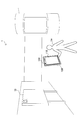
- FIG. 1 is an explanatory diagram for explaining an outline of an apparatus according to an embodiment.
- an image processing apparatus 100 included in a user Ua is shown.
- the image processing apparatus 100 includes a camera 102 that images the real space 1 and a display 110.
- a real object 10 exists in the real space 1.
- the camera 102 of the image processing apparatus 100 captures the real object 10 to generate a series of images that constitute an image showing the real object 10.
- the image processing apparatus 100 performs image processing using a captured image generated by the camera 102 as an input image, and generates an output image.
- the output image is generated by superimposing a display object for navigation on the input image.
- the display 110 of the image processing apparatus 100 sequentially displays the generated output images.
- the real space 1 shown in FIG. 1 is merely an example.
- the image processing apparatus 100 may process an image showing any real object.
- FIG. 1 shows a smartphone as an example of the image processing apparatus 100.
- the image processing apparatus 100 is not limited to such an example.
- the image processing apparatus 100 may be a mobile device such as a tablet PC (Personal Computer), a notebook PC, a portable game terminal, a PND (Portable Navigation Device), or a digital camera.
- the image processing apparatus 100 may be a wearable device such as an HMD (Head Mounted Display) terminal.
- HMD Head Mounted Display
- an image showing a visual recognition target of a real object is acquired as an input image.
- the recognition target here may be a known figure, symbol, character string, or picture that appears in the appearance of a real object, or any combination thereof.
- the recognition target may include a visual code (for example, a bar code or a cyber code (registered trademark)) in which some information is encoded.
- the image processing apparatus 100 stores feature data about the recognition target in advance, and recognizes the arrangement of the recognition target shown in the input image (relative arrangement from the imaging surface) using the feature data.
- the term “arrangement” includes at least one of position (parallel movement), posture (rotation), and size (scaling) in a two-dimensional or three-dimensional coordinate system.
- the feature data may include, for example, data on a set of feature points extracted from a known image to be recognized.
- the feature data may include data on the shape and size of a known graphic pattern.
- FIG. 2 is an explanatory diagram showing an example of a real object having a recognition target.
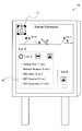
- the real object 10 is a guide plate installed in a public facility such as a station.
- the guide plate 10 has a recognition object 11 that can be printed or affixed on the surface thereof.
- the recognition target 11 includes a figure imitating the alphabet “i” and a black and white frame surrounding the figure.
- the image processing apparatus 100 collates a plurality of feature points extracted from the input image with a feature point set stored in advance for the recognition target 11, thereby displaying the recognition target 11 in the input image in any arrangement. Can be recognized.
- the guide plate 10 has a destination list 15 on its surface. By viewing the destination list 15, the user can know major spots existing around the place where the guide plate 10 is installed. However, the destination list 15 does not indicate in which direction the individual spots exist. Even if the guide board 10 has a map and the position of each spot is shown on the map, the destination is shown on the two-dimensional map (and almost always displayed vertically). It is difficult to intuitively express the direction toward Therefore, the user is forced to perform mapping between the direction on the map and the direction in the real space in his / her head. In order to eliminate such inconvenience, some navigation services acquire the current position of the terminal through a positioning module such as a GPS module installed in the terminal and acquire the attitude of the terminal through a sensor. Guide the user to.
- a positioning module such as a GPS module installed in the terminal and acquire the attitude of the terminal through a sensor. Guide the user to.
- the arrangement of the terminal is determined based on the above-described image recognition performed on the recognition target 11, and navigation for guiding the user to the destination is provided according to the determination result. Thereby, the need to rely on positioning modules is avoided.
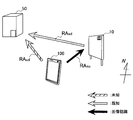
- FIG. 3 is an explanatory diagram for explaining the principle of navigation in one embodiment.
- a real object 10 having a recognition target, a selected destination 50, and an image processing apparatus 100 that captures the real object 10 are illustrated. Since the real object 10 and the destination 50 are geographically fixed, the relative position RA sd between the destination 50 and the real object 10 is known. Note that since the orientation and size of the destination 50 do not affect navigation, the term “position” is used instead of “placement”.
- the relative arrangement RA su with the real object 10 of the image processing apparatus 100 is determined based on the image recognition of the recognition target of the real object.
- the unknown relative position RA ud between the destination 50 and the image processing apparatus 100 is the relative arrangement RA su between the real object 10 of the image processing apparatus 100 and the actual position 50 of the destination 50. It is derived using the relative position RA sd with the object 10.
- the image processing apparatus 100 can display a display object for navigation corresponding to the relative position RA ud on the screen.
- the present invention is not limited to the examples in FIGS. 2 and 3, and any real object existing in the real space may have a recognition target.
- the recognition target may be printed or pasted on a floor map of a commercial facility, an advertisement signboard, an event poster, or the like, or the recognition target may be electronically displayed by digital signage.
- the recognition target may be printed or pasted on a floor map of a commercial facility, an advertisement signboard, an event poster, or the like, or the recognition target may be electronically displayed by digital signage.
- FIG. 4 is a block diagram illustrating an example of a hardware configuration of the image processing apparatus 100 according to an embodiment.
- the image processing apparatus 100 includes a camera 102, a positioning module 104, an input interface 106, a memory 108, a display 110, a communication interface 112, a sensor module 114, a bus 116, and a processor 118.
- the camera 102 is an imaging module that captures an image.
- the camera 102 images a real object using an image sensor such as a charge coupled device (CCD) or a complementary metal oxide semiconductor (CMOS), and generates a captured image.
- CCD charge coupled device
- CMOS complementary metal oxide semiconductor
- a series of captured images generated by the camera 102 constitutes a video.
- the positioning module 104 may be a GPS (Global Positioning System) module or PlaceEngine (registered trademark).
- the positioning module 104 acquires the geographical position of the image processing apparatus 100 by receiving the wireless signal in an environment where the wireless signal for positioning can be received. Then, the positioning module 104 generates positioning data indicating the acquired geographical position.
- the geographical position refers to an absolute position in the global coordinate system. Note that the positioning module 104 may be omitted from the configuration of the image processing apparatus 100.
- the input interface 106 is an input device used for a user to operate the image processing apparatus 100 or input information to the image processing apparatus 100.
- the input interface 106 may include, for example, a touch sensor that detects a user touch on the screen of the display 110.
- the input interface 106 may also include an input device such as a keyboard, keypad, button, or switch.
- the input interface 106 may include a microphone for voice input and a voice recognition module.
- the memory 108 is a storage medium such as a semiconductor memory or a hard disk.
- the memory 108 stores a program and data for processing by the image processing apparatus 100.
- Data stored by the memory 108 may include, for example, captured image data, positioning data, sensor data, and data in various databases (DB) described later.
- DB databases
- some of the programs and data described in this specification may be acquired from an external data source (for example, a data server, a network storage, or an external memory) without being stored in the memory 108.
- the display 110 is a display module having a screen for displaying an image.
- the display 110 may be, for example, an LCD (Liquid Crystal Display), an OLED (Organic light-Emitting Diode), or a CRT (Cathode Ray Tube).
- the display 110 displays, for example, an output image on which a display object for navigation generated by the image processing apparatus 100 is superimposed.
- the communication interface 112 is a communication interface that mediates communication between the image processing apparatus 100 and other apparatuses.
- the communication interface 112 supports any wireless communication protocol or wired communication protocol, and establishes a communication connection with other devices.
- the sensor module 114 may include a sensor group such as a gyro sensor, a geomagnetic sensor, and an acceleration sensor.
- the sensor module 114 measures the attitude of the image processing apparatus 100, for example.
- the sensor module 114 measures the movement of the image processing apparatus 100.
- the sensor module 114 generates sensor data indicating the measured posture and movement. Sensor data generated by the sensor module 114 can be used to track changes in the placement of the image processing device 100. Note that the sensor module 114 may be omitted from the configuration of the image processing apparatus 100.
- the bus 116 connects the camera 102, the positioning module 104, the input interface 106, the memory 108, the display 110, the communication interface 112, the sensor module 114, and the processor 118 to each other.
- the processor 118 corresponds to a processor such as a CPU (Central Processing Unit) or a DSP (Digital Signal Processor).
- the processor 118 operates various functions of the image processing apparatus 100 described later by executing a program stored in the memory 108 or other storage medium.
- FIG. 5 is a block diagram illustrating an example of a configuration of logical functions realized by the memory 108 and the processor 118 of the image processing apparatus 100 illustrated in FIG.
- the image processing apparatus 100 includes an image acquisition unit 140, a recognition database (DB) 150, a recognition unit 160, an object arrangement DB 170, and a control unit 180.
- DB recognition database
- the image acquisition unit 140 acquires an image captured by the camera 102 as an input image.
- An input image is typically each of a series of frames that make up a video.
- the input image is an image showing a real object having a visual recognition target. Then, the image acquisition unit 140 outputs the acquired input image to the recognition unit 160 and the control unit 180.
- the recognition DB 150 is a database that stores recognition dictionary data used by the recognition unit 160 described later.
- the recognition dictionary data includes, for each of one or more recognition objects, feature data that defines the characteristics of the recognition object.
- the recognition dictionary data may include additional code placement data that defines the placement of additional code that the real object additionally has.
- FIG. 6A is an explanatory diagram showing a first example of a configuration of recognition dictionary data that can be stored by the recognition DB 150.
- the recognition dictionary data 151 a includes a code ID 152 and feature data 153.
- the code ID 152 is an identifier for uniquely identifying the recognition target.
- the feature data 153 defines known features for each recognition target.
- the feature data 153 may define a feature amount set extracted in advance from a known image of the recognition target.
- the feature quantity set may include the position coordinates of each of the plurality of feature points in the local coordinate system of the real object and the brightness of the feature points.
- the feature data 153 may define the shape and size of a known pattern.
- FIG. 6B is an explanatory diagram showing a second example of the configuration of recognition dictionary data that can be stored by the recognition DB 150.
- the recognition dictionary data 151b includes a code ID 152, feature data 153, and additional code arrangement data 154.
- the additional code arrangement data 154 includes a code type 155, a position offset 156, a rotation 157 and a size 158.
- the code type 155 defines the type of additional code (for example, bar code, cyber code (registered trademark), etc.).
- the position offset 156 defines the offset of the reference position of the additional code from the reference position to be recognized (for example, the origin of the local coordinate system).
- the rotation 157 defines the rotation amount of the additional code around the reference position (for example, the rotation amount on the surface of the real object). Size 158 defines the size of the additional code.
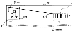
- FIG. 7 is an explanatory diagram for describing the additional code arrangement data 154 illustrated in FIG. 6B.
- the asterisk indicates the positions of a plurality of feature points of the recognition target 11 including the feature point FP1 in the local coordinate system C Local .
- the position coordinate OF1 is a vector value defined by the position offset 156, and is equal to the coordinate in the local coordinate system C Local of the upper left vertex of the bounding box surrounding the additional code.
- the rotation 157 may define a rotation amount of zero.
- the width W and height H of the bounding box surrounding the additional code can be defined by size 158.
- the recognizing unit 160 recognizes the relative arrangement of the terminal that captured the input image with the real object having the recognition target by executing image recognition on the recognition target.
- the terminal that captured the input image is the image processing apparatus 100.
- the recognition unit 160 may recognize a recognition target shown in the input image by collating an image feature amount extracted from the input image with a known feature amount set stored in the recognition DB 150. Further, the recognition unit 160 may recognize a recognition target shown in the input image by collating a pattern included in the input image with a known pattern stored in the recognition DB 150. Further, the recognizing unit 160 recognizes the arrangement of the recognition target in the input image from the positional relationship between the detected feature points or the shape and size of the detected pattern.
- the recognition unit 160 generates a parameter expressing the relative arrangement of the recognition target from the imaging surface as a result of the image recognition.
- the parameter generated by the recognition unit 160 may be a homogeneous transformation matrix in a three-dimensional screen coordinate system corresponding to the imaging surface and its depth. This homogeneous transformation matrix substantially represents a relative arrangement with the real object of the image processing apparatus 100.
- the recognition unit 160 outputs the recognized recognition target identifier (code ID) and the corresponding parameter (for example, a homogeneous transformation matrix) to the control unit 180.
- the recognizing unit 160 further encodes, from the recognition target or the additional code, when the information is encoded by the detected recognition target or the additional code added to the surface of the real object in association with the recognition target.
- the information that has been converted may be decrypted.
- the information decoded by the recognition unit 160 may include identification information of a recognition target (or real object) that can be used for an inquiry to the data server.
- the information decoded by the recognition unit 160 may include object arrangement data indicating at least one of the geographical arrangement of the real object and the position of the destination as described later.
- the recognizing unit 160 specifies an area where the additional code exists according to the additional code arrangement data 154 illustrated in FIG. 6B.
- the recognizing unit 160 executes a recognition process (for example, reading of a barcode) according to the code type of the additional code for the partial image in the specified area.
- a recognition process for example, reading of a barcode
- information encoded by the additional code can be decoded.
- the object arrangement data may be acquired from an external data server using the identification information of the real object instead of being decoded from the recognition target or the additional code.
- the object arrangement DB 170 is a database that stores object arrangement data.
- the object arrangement data can be used to determine the direction toward the destination by the control unit 180 described later.
- FIG. 8A is an explanatory diagram showing a first example of the configuration of the object arrangement data.
- the object arrangement data 171a includes an object ID 172a, a type 173, a name 174, a geographical position 175, and a posture 176.
- the object ID 172a is an identifier for identifying each of a real object having a recognition target and a destination candidate.
- the type 173 identifies what kind of object each object is (for example, a guide board or a destination candidate).
- the name 174 defines a name on the display of each object.
- the geographic position 175 defines the position (eg, latitude, longitude, and altitude) of each object in the global coordinate system.
- the posture 176 defines the posture of each object in the global coordinate system. Note that the value of the posture 176 may be omitted for the destination candidates.
- FIG. 8B is an explanatory diagram showing a second example of the configuration of the object arrangement data.
- the object arrangement data 171b includes a code ID 172b, a name 174, a destination ID 177, a destination name 178, and a relative arrangement 179.
- the code ID 172b is an identifier for identifying each real object (or recognition target) having a recognition target.
- the destination ID 177 is an identifier for identifying each destination candidate. In the example of FIG. 8B, one or more destination candidates are associated with one recognition target.
- the destination name 178 defines the name on the display of each candidate destination.
- Relative placement 179 defines the relative placement of each candidate destination with the associated real object. Relative placement 179 may be strictly defined using coordinate values, or may be coarsely defined using simple segment values such as east, south, west, north, top and bottom.
- the object arrangement data described above may be stored in advance by the object arrangement DB 170. Further, part or all of the object arrangement data may be dynamically acquired from an external data server. Further, as described above, a part or all of the object arrangement data may be decoded by the recognition unit 160 from the recognition target or the additional code associated with the recognition target.
- Control Unit 180 displays, on the screen of the display 110, a display object indicating a direction toward the user's destination based on the relative arrangement from the real object of the image processing apparatus 100 recognized by the recognition unit 160. Display.
- the control unit 180 determines the direction toward the destination from the relative arrangement of the terminals recognized by the recognition unit 160, the geographical arrangement of the real object indicated by the object arrangement data, and the geographical position of the destination. May be. More specifically, for example, the control unit 180 determines the geographical arrangement of the terminal from the geographical arrangement (for example, latitude, longitude, altitude and orientation) of the real object and the relative arrangement of the terminal with respect to the real object. . Furthermore, if the geographical position of the destination is obtained, the control unit 180 can determine a vector corresponding to the direction toward the destination in the screen coordinate system of the terminal.
- control unit 180 determines the direction toward the destination from the relative arrangement of the terminal recognized by the recognition unit 160 and the relative position between the real object at the destination indicated by the object arrangement data. May be. More specifically, for example, the control unit 180 adds the relative position of the destination with respect to the real object to the relative arrangement of the real object with respect to the terminal, thereby obtaining a vector corresponding to the direction toward the destination. In the screen coordinate system.
- the direction toward the destination can be intuitively presented to the user on the screen using the display object.
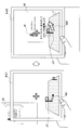
- FIG. 9 is an explanatory diagram illustrating an example of a change in the output image accompanying a change in the attitude of the terminal.
- 9 shows the positional relationship between the guide plate 10 and the image processing apparatus 100 at a certain point in time, and the imaging surface of the image processing apparatus 100 faces the guide plate 10.
- the recognition unit 160 performs image recognition on a recognition target on the surface of the guide plate 10 and generates a parameter RA SU that represents a relative arrangement between the image processing apparatus 100 and the guide plate 10.
- An output image Im01 as an example is shown on the lower left of FIG.
- a display object N01 for navigation indicating the direction toward the destination is superimposed on the output image Im01.
- the control unit 180 determines the orientation RA ud of the display object N01 according to the parameter RA SU .
- the display object H01 represents a horizontal plane for assisting the user to grasp the three-dimensional orientation of the display object N01.
- the upper right of FIG. 9 shows the positional relationship between the guide plate 10 and the image processing apparatus 100 at the subsequent time point, and the image processing apparatus 100 is tilted so that the imaging surface approaches more horizontal.
- the parameter RA SU ′ represents a relative arrangement between the image processing apparatus 100 and the guide plate 10 at this time.
- An output image Im02 as an example is shown on the lower right side of FIG. On the output image Im02, a display object N02 having an orientation RA ud 'determined according to the parameter RA SU ' is superimposed.
- the display object H02 represents a horizontal plane.
- FIG. 10 is an explanatory diagram showing how the output image illustrated in FIG. 9 is seen from the user's viewpoint.
- the display object N01 superimposed on the output image Im01 indicates the left front as viewed from the user's viewpoint.
- the display object N02 superimposed on the output image Im02 shows the left front as seen from the user's viewpoint, regardless of the change in the attitude of the terminal. Therefore, even if the user moves the terminal, the user can intuitively know the direction in which the destination exists in the real space.
- the controller 180 continuously displays the display object for navigation by tracking the relative arrangement of the terminal using the sensor data from the sensor module 114 after the recognition target once recognized deviates from the angle of view. May be displayed.
- the control unit 180 can track the change in the position of the terminal by integrating the acceleration of the terminal measured by the acceleration sensor.
- the control unit 180 can track the change in the attitude of the terminal by integrating the rotation of the terminal measured by the gyro sensor.
- the control part 180 can track the attitude
- the control unit 180 may correct the arrangement of the tracked terminals using the positioning data from the positioning module.
- FIG. 11 is an explanatory diagram for explaining an example of tracking of the arrangement of the terminal accompanying the movement of the terminal.
- the control unit 180 determines the arrangement of the image processing apparatus 100 based on the result of image recognition executed by the recognition unit 160. can do.
- the control unit 180 still places the image processing apparatus 100 based on the result of image recognition. Can be determined.
- the control unit 180 can continuously display the display object for navigation on the screen by tracking the arrangement of the image processing apparatus 100 using the sensor data, and can provide the navigation service to the user.
- the accuracy of tracking using sensor data can decrease as the duration increases.
- the positioning module 104 can be used. Therefore, the control unit 180 acquires the geographical position of the image processing apparatus 100 through the positioning module 104, thereby correcting the arrangement of the image processing apparatus 100 being tracked.
- the attitude of the image processing apparatus 100 may also be corrected using sensor data.
- the control unit 180 may cause the user to select a destination to be navigated by displaying a list of destination candidates or a map associated with the recognized real object on the screen. Instead, the control unit 180 may cause the user to select a destination to be navigation target in advance. In addition, the control unit 180 displays a plurality of display objects on the screen, each indicating a direction toward a plurality of destination candidates associated with the recognized real object, when a single destination is not selected by the user. You may let them.
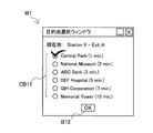
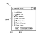
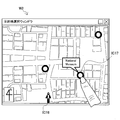
- FIGS. 12A to 12C show examples of windows for allowing the user to select a destination.
- the destination selection window W1 includes a check box CB11 and a button B12.
- the check box CB11 indicates a list of destination candidates associated with the real object recognized by the recognition unit 160 (for example, existing around the place where the guide board is installed). The user checks any candidate in the check box CB11 and taps the button B12. As a result, a destination to be navigated is selected.
- the destination selection window W2 includes a check box CB13, a button B14, and a button B15.
- Check box CB13 shows some of the list of all destination candidates. The user may select a desired destination by tapping the button B14 after checking any candidate in the check box CB13. Instead, the user may transition to the next page by tapping button B15, and display some other of the list of destination candidates in destination selection window W2.
- the destination candidates may be grouped, for example, for each nearest station, and the destination candidates listed may be filtered according to the selection of the nearest station.
- the destination selection window W3 includes a map around the geographical position of the real object recognized by the recognition unit 160 and a plurality of icons plotted on the map.
- the icon IC16 indicates the current location (that is, the geographical position of the recognized real object).
- the icon IC17 indicates one position of the destination candidate. The user can select a destination to be navigated by tapping an icon corresponding to the desired destination.
- the output image for navigation can include various display objects for improving usability.
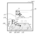
- 13A-13D illustrate some examples of display objects that may be displayed in one embodiment.
- display objects N11 and H11 and auxiliary display objects J11, J12, J13, J14 and J15 are superimposed on the output image Im11.
- the display object N11 indicates a direction from the current location to the destination.
- the display object H11 is an object that represents a horizontal plane.
- the auxiliary display object J11 is an object that represents the aim of image recognition.
- the auxiliary display object J12 is an icon that represents the current location.
- the auxiliary display object J13 is an icon that represents a destination.
- the auxiliary display object J14 is a slider for the user to change the scale for displaying the current location, the destination, and other locations.
- the auxiliary display object J15 is an icon representing a spot other than the destination (for example, a guide board or a destination candidate not selected).
- the display object N12 and auxiliary display objects J12, J13, and J16 are superimposed on the output image Im12.
- the display object N12 indicates a direction from the current location to the destination.
- the display object N12 has a non-linear path (for example, the user can pass through to the destination) as opposed to the display object N11 illustrated in FIG. 13A indicating the linear direction toward the destination.
- the auxiliary display object J16 indicates the detection position of the recognition target 11 in the input image. By visually recognizing the auxiliary display object J16, the user can know that the recognition target has been successfully recognized and which part of the image is useful for highly accurate navigation.
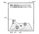
- the third example of FIG. 13C shows an output image Im13 that can be displayed while tracking using the sensor data is continued.
- a display object N13, auxiliary display objects J13, J17, and J18, and a message M11 are superimposed on the output image Im13.
- the display object N13 indicates a direction from the current location to the destination. However, the outline of the display object N13 is thin, which indicates to the user that the tracking accuracy may be reduced.
- the auxiliary display objects J17 and J18 are icons representing the position of a guide board (real object having a recognition target) existing in the vicinity of the estimated current location.
- Message M11 suggests to the user to hold the camera over a nearby guide board.
- the fourth example in FIG. 13D shows an output image Im14 when navigation is performed for a plurality of destinations.
- Display objects N11a, N11b, and N11c and auxiliary display objects J13a, J13b, and J13c are superimposed on the output image Im14.
- the display object N11a indicates a direction from the current location toward the first destination.
- the auxiliary display object J13a is an icon that represents the first destination.
- the display object N11b indicates a direction from the current location toward the second destination.
- the auxiliary display object J13b is an icon that represents the second destination.
- the display object N11c indicates a direction from the current location toward the third destination.
- the auxiliary display object J13c is an icon that represents the third destination.
- FIGS. 13A to 13D may be combined and displayed on the screen.
- FIG. 14 is a flowchart illustrating an example of the flow of image processing executed by the image processing apparatus 100 according to the present embodiment. The process illustrated in FIG. 14 is repeated for each of a series of input images captured by the camera 102.
- the image acquisition unit 140 acquires an input image showing a real object having a visual recognition target from the camera 102 (step S100). Then, the image acquisition unit 140 outputs the acquired input image to the recognition unit 160 and the control unit 180.
- the recognition unit 160 performs image recognition on the recognition target using the recognition dictionary data stored in the recognition DB 150 (step S102). Then, the recognizing unit 160 determines whether or not a recognition target is detected in the input image (step S104). If a recognition target is detected, the process proceeds to step S110. On the other hand, if the recognition target is not detected, the process proceeds to step S130.
- the recognition unit 160 recognizes the position and orientation of the terminal at that time by executing the terminal arrangement determination process (step S110). Some examples of the detailed flow of the terminal arrangement determination process executed here will be further described later.
- the control unit 180 determines whether the positioning module 104 is available (step S130). When the positioning module 104 is available, the control unit 180 acquires the geographical position of the image processing apparatus 100 through the positioning module 104 (step S132). Further, the control unit 180 acquires sensor data indicating the posture of the image processing apparatus 100 from the sensor module 114 (step S134).
- the control unit 180 determines whether or not to keep track of the arrangement of the image processing apparatus 100 (step S136). Placement tracking can be used for various events such as explicit instructions from the user, passage of a predetermined time since the last time the recognition target was detected, detection of movement exceeding a threshold, or arrival at the destination. May be terminated accordingly. If it is determined not to continue the tracking of the arrangement, the process returns to step S100, and the above-described process is repeated for the next input image. When it is determined that the tracking of the arrangement is to be continued, the control unit 180 uses the sensor data from the sensor module 114 to integrate the change in the arrangement of the image processing apparatus 100 from the time when the recognition target was previously detected. The arrangement of the image processing apparatus 100 is traced (step S138).
- step S110 When the current arrangement of the image processing apparatus 100 is determined in step S110, step S134, or step S138, the control unit 180 executes the destination direction determination process, thereby performing a destination in the screen coordinate system of the image processing apparatus 100. A direction toward the ground is determined (step S140). Some examples of the detailed flow of the destination direction determination process executed here will be further described later.
- control unit 180 generates a display object for navigation indicating the determined direction (step S162).
- the control unit 180 may further generate one or more auxiliary display objects that can represent a horizontal plane, a current location, a destination, or an aim of recognition.
- the control unit 180 generates an output image by superimposing the generated display object image on the input image, and displays the generated output image on the screen of the display 110 (step S164). Thereafter, the process returns to step S100, and the above-described process is repeated for the next input image.
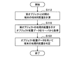
- FIG. 15A is a flowchart showing a first example of a detailed flow of the terminal arrangement determination process shown in FIG.
- the object arrangement data is acquired from an external data server.
- the recognizing unit 160 recognizes an actual feature that has been recognized based on an image feature amount extracted from an input image or a result of matching between a pattern included in the input image and feature data included in the recognition dictionary data.
- the relative arrangement of the image processing apparatus 100 with the object is calculated (step S112).
- the recognizing unit 160 uses the identification information of the recognized real object to transmit a data request to an external data server, thereby acquiring object arrangement data indicating the geographical arrangement of the real object from the data server ( Step S116). Then, the recognition unit 160 stores the acquired object arrangement data in the object arrangement DB 170.
- the recognition unit 160 determines the geographical arrangement of the image processing apparatus 100 from the geographical arrangement of the real object indicated by the acquired object arrangement data and the relative arrangement of the image processing apparatus 100 with the real object. Determination is made (step S122).
- step S122 may be omitted.
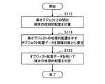
- FIG. 15B is a flowchart illustrating a second example of a detailed flow of the terminal arrangement determination process shown in FIG.
- the object arrangement data is decoded from the detected recognition target.
- the recognition unit 160 recognizes an actual feature that has been recognized based on an image feature amount extracted from the input image or a result of matching between a pattern included in the input image and feature data included in the recognition dictionary data.
- the relative arrangement of the image processing apparatus 100 with the object is calculated (step S112).
- the recognizing unit 160 acquires object arrangement data indicating the geographical arrangement of the real object having the recognition target by decoding the object arrangement data encoded in the recognition target (step S118). Then, the recognition unit 160 stores the acquired object arrangement data in the object arrangement DB 170.
- the recognition unit 160 determines the geographical arrangement of the image processing apparatus 100 from the geographical arrangement of the real object indicated by the acquired object arrangement data and the relative arrangement of the image processing apparatus 100 with the real object. Determination is made (step S122).
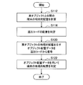
- FIG. 15C is a flowchart showing a third example of a detailed flow of the terminal arrangement determination process shown in FIG.
- the object arrangement data is decoded from the additional code added to the surface of the real object in association with the detected recognition target.
- the recognition unit 160 recognizes an actual feature that has been recognized based on an image feature amount extracted from the input image or a result of matching between a pattern included in the input image and feature data included in the recognition dictionary data.
- the relative arrangement of the image processing apparatus 100 with the object is calculated (step S112).
- the recognition unit 160 determines the arrangement of the additional code in the input image using the additional code arrangement data included in the recognition dictionary data (step S114).
- the recognizing unit 160 obtains object arrangement data indicating the geographical arrangement of the real object by decoding the object arrangement data encoded in the additional code (step S120). For example, the recognizing unit 160 applies a recognition process for reading the additional code to the partial image including the additional code after deforming the input image so that the surface to which the additional code is added faces the input image. May be. Then, the recognition unit 160 stores the acquired object arrangement data in the object arrangement DB 170.
- the recognition unit 160 determines the geographical arrangement of the image processing apparatus 100 from the geographical arrangement of the real object indicated by the acquired object arrangement data and the relative arrangement of the image processing apparatus 100 with the real object. Determination is made (step S122).
- FIG. 16A is a flowchart showing a first example of a detailed flow of the destination direction determination process shown in FIG. In the first example, the direction toward the destination is determined from the geographical location of the destination and the geographical location of the terminal.
- the control unit 180 determines one or more destinations to be navigated (step S142). For example, the control unit 180 may determine a destination selected by the user via a user interface as illustrated in FIGS. 12A to 12C as a navigation target. Instead, the control unit 180 automatically determines one or more spots present in the vicinity, a spot selected according to the navigation route, or a spot selected for the purpose of advertisement as a navigation target. Also good.
- control unit 180 acquires the geographical position of the determined destination from the object arrangement data stored in the object arrangement DB 170 (step S144).
- control unit 180 calculates a direction toward the destination in the screen coordinate system of the image processing apparatus 100 from the acquired geographical position of the destination and the geographical arrangement of the image processing apparatus 100 (step S148).
- FIG. 16B is a flowchart showing a second example of a detailed flow of the destination direction determination process shown in FIG.
- the direction toward the destination is determined from the relative position of the destination relative to the real object and the relative arrangement of the terminals.
- control unit 180 determines one or more destinations as navigation targets (step S142).
- control unit 180 acquires the relative position of the determined destination from the real object from the object arrangement data stored in the object arrangement DB 170 (step S146).
- control unit 180 calculates a direction toward the destination in the screen coordinate system of the image processing apparatus 100 from the acquired relative position of the destination and the relative arrangement of the image processing apparatus 100 (step S150).
- stamp Rally The technology according to the present disclosure can be applied to various uses. As an example, the use of the stamp rally will be described here. A stamp rally generally enjoys collecting stamps or responding to the collection results by visiting a plurality of spots sharing a certain theme in sequence and stamping the stamp placed on each spot on a stamp card. It is an event that tries to acquire special benefits. Instead of stamping a stamp on a stamp card, there is also a technique in which a user images a mark placed at each spot as evidence that the user has visited each spot.
- FIG. 17 is an explanatory diagram illustrating some examples of display objects that can be displayed in an application example of a stamp rally.
- a display object N21 and an auxiliary display object J21 are superimposed on the output image Im21 shown on the left in FIG.
- the display object N21 indicates a direction from the current location toward the next spot in the stamp rally.
- the auxiliary display object J21 is an icon that represents the next spot as a destination.
- the real object 40 is shown in the output image Im22 shown on the right side of FIG.
- the real object 40 is a poster posted at the spot of the stamp rally. That is, the user has reached one spot at this point, and then aims for the next spot.
- a recognition target 41 is printed on the printing surface of the poster 40.
- the recognition unit 160 of the image processing apparatus 100 recognizes the relative arrangement of the image processing apparatus 100 with the poster 40 by executing image recognition on the recognition target 41. Then, the control unit 180 determines the direction toward the next spot using the relative arrangement of the image processing apparatus 100 and the object arrangement data acquired in association with the poster 40.
- a display object N22 and an auxiliary display object J21 are superimposed on the output image Im22.
- the auxiliary display object J21 is highlighted so as to notify that the user has reached the spot where the poster 40 is posted.
- the display object N22 indicates a direction toward the next spot determined based on the image recognition.
- a recognition target common to a plurality of spots and an additional code for identifying each spot may be prepared. Instead, different recognition objects may be prepared for a plurality of spots.
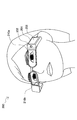
- FIG. 18 is an explanatory diagram for describing a modification of the image processing apparatus.
- the image processing apparatus 200 is a glasses-type HMD terminal worn on the user's head.
- the image processing apparatus 200 includes a housing 201, a camera 202, a contact surface 206, and a pair of screens 210a and 210b.
- the casing 201 includes a frame that supports the screens 210a and 210b, and a so-called temple that is positioned on the user's temporal region. Inside the temple are stored several modules including a memory and a processor for image processing.
- the camera 202 is disposed so that the optical axis of the lens is substantially parallel to the user's line of sight, and is used to capture an image.
- the contact surface 206 is a surface that detects a touch by the user, and is used by the image processing apparatus 200 to accept a user input.
- the screens 210a and 210b are see-through type or non-see-through type screens arranged in front of the user's left eye and right eye, respectively.
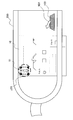
- FIG. 19 is an explanatory diagram showing some examples of display objects that can be displayed in the modification of FIG.
- a display object N31, a display object H31, and an auxiliary display object J31 are displayed on the screen of the image processing apparatus 200.
- the display object N31 is a navigation object indicating a direction from the current location to the destination.
- the display object H31 is an object that represents a horizontal plane.
- the auxiliary display object J31 is an object indicating the detection position of the recognition target in the input image.
- the auxiliary display object J31 may be a static icon or an animation.
- the recognition target 11 of the real object 10 is detected.
- the navigation display object can be displayed at the end of the screen as in the example of FIG. 19, so that the navigation service can be safely provided without disturbing the user's view.
- the user interface for selecting a destination may be displayed on the screens 210a and 210b, or may be displayed on the screen of another device (for example, a smartphone held by the user) that cooperates with the image processing device 200. Good.
- the technology according to the present disclosure may be realized by a plurality of devices cooperating with each other.
- some of the functions of the recognition unit 160 and the control unit 180 described above may be executed by a device physically different from the image processing device 100 or 200.
- FIG. 20 is an explanatory diagram for explaining the cooperation of a plurality of devices.
- an image processing apparatus 100 and a server apparatus 300 that communicates with the image processing apparatus 100 are shown.
- the server device 300 may be arranged on a personal network or a home network constructed in the vicinity of the user, or may be arranged on a remote network such as the Internet.
- the image processing apparatus 100 transmits an input image to the server apparatus 300 (SIG1).
- the server device 300 is a device having the functions of the recognition unit 160 and the control unit 180 shown in FIG.
- the server apparatus 300 performs image recognition on the input image received from the image processing apparatus 100 and recognizes a real object having a recognition target.
- the server apparatus 300 transmits information corresponding to the image recognition result to the image processing apparatus 100 (SIG2).
- Information transmitted from the server apparatus 300 to the image processing apparatus 100 includes a parameter indicating the relative arrangement of the image processing apparatus 100 with the real object, a parameter indicating the direction toward the destination of the user, or the direction toward the destination.
- Graphic data of a display object indicating The image processing apparatus 100 uses the information received from the server apparatus 300 to display an output image on which the display object indicating the direction toward the destination is superimposed on the screen. According to this configuration, even when the image processing apparatus 100 has only a few processing resources, a navigation service can be provided to the user.
- the destination may be selected by the user via a screen displaying a list or map of destination candidates associated with the captured real object. According to such a configuration, it is possible for the user to easily select main spots existing around a real object having a recognition target as a destination.
- a user images a poster on which an image of a target product for advertisement is printed, an application in which the user selects a nearby store that sells the target product and guides the user to the store is also possible.
- the destination may be selected in advance by the user. One or more destinations may be automatically selected.
- the direction toward the destination can be determined from the relative arrangement of the terminals, the geographical arrangement of the real object, and the geographical position of the destination. Usually, since the geographical location of the real object and the geographical location of the destination do not change, according to such a configuration, the location of the dynamically recognized terminal and the predefined data are used to go to the destination. The direction can be determined appropriately. As another example, the direction toward the destination can be determined from the relative location of the terminal and the relative position between the destination and the real object. Also in this case, the direction toward the destination can be appropriately determined using the dynamically recognized terminal arrangement and the predefined data.
- the data defining the placement of the real object or the location of the destination is dynamically acquired from the data server, it is not necessary to distribute the data to each terminal in advance, so that the above-described mechanism can be easily introduced.
- the data defining the arrangement of the real object or the position of the destination is visually encoded on the surface of the real object, there is no need to distribute the data to each terminal in advance.
- the need to communicate with the data server is also avoided. Therefore, the navigation service can be provided to the user even in a situation where neither the positioning module nor the wireless communication module is available.
- the arrangement of the terminal is tracked using the sensor data from the sensor of the terminal, and the display object indicating the direction toward the destination is continuously displayed on the screen. Therefore, it is possible to provide the navigation service to the user without interruption even while the user is moving.
- a series of control processing by each device described in this specification may be realized using any of software, hardware, and a combination of software and hardware.
- the program constituting the software is stored in advance in a storage medium (non-transitory medium) provided inside or outside each device.
- Each program is read into a RAM (Random Access Memory) at the time of execution and executed by a processor such as a CPU.
- processing described using the flowchart in this specification does not necessarily have to be executed in the order shown in the flowchart. Some processing steps may be performed in parallel. Further, additional processing steps may be employed, and some processing steps may be omitted.
- An image acquisition unit for acquiring an image showing a real object having a visual recognition target;
- a recognition unit that recognizes a relative arrangement between the real object of the terminal that has captured the image by performing image recognition on the recognition target;
- a control unit that displays on the screen of the terminal a display object indicating a direction toward the user's destination;
- An image processing apparatus comprising: (2) The image processing apparatus according to (1), wherein the control unit causes the user to select the destination by displaying a list or map of destination candidates associated with the real object on the screen.
- the control unit displays, on the screen, a plurality of display objects each indicating a direction toward a plurality of destination candidates associated with the real object when a single destination is not selected by the user;
- the image processing apparatus according to any one of (1) to (3).
- the display object indicates a linear direction toward the destination or the direction along a non-linear route.
- the control unit determines the direction to be indicated by the display object from the relative arrangement of the terminal, the geographical arrangement of the real object, and the geographical position of the destination, (1) to (6) The image processing apparatus according to any one of the above.
- the control unit determines the direction to be indicated by the display object from the relative arrangement of the terminal and the relative position between the destination and the real object. (1) to (6) The image processing apparatus according to any one of the above.
- the control unit causes the display object to be continuously displayed on the screen by tracking the arrangement of the terminal using sensor data from the sensor of the terminal, and any one of (1) to (8) The image processing apparatus according to claim 1.
- the control unit corrects the arrangement of the terminal to be tracked using the positioning data from the positioning module, (9) An image processing apparatus according to 1.
- the geographical arrangement of the real object is decoded from an additional code on a surface of the real object associated with the recognition target or the recognition target.
- the image processing apparatus according to (8), wherein the relative position of the destination is decoded from an additional code on a surface of the real object associated with the recognition target or the recognition target.
- the image processing apparatus is the terminal.
- the image processing device is a server device that communicates with the terminal.
- An image processing method executed by an image processing apparatus Obtaining an image of a real object having a visual recognition target; Recognizing a relative arrangement between the real object of the terminal that captured the image by performing image recognition on the recognition target; Displaying a display object indicating a direction toward the user's destination on the screen of the terminal based on the recognized relative arrangement of the terminal;
- An image processing method including: (18) A computer for controlling the image processing apparatus; An image acquisition unit for acquiring an image showing a real object having a visual recognition target; A recognition unit that recognizes a relative arrangement between the real object of the terminal that has captured the image by performing image recognition on the recognition target; Based on the relative arrangement of the terminal recognized by the recognition unit, a control unit that displays a display object indicating a direction toward the user's destination on the screen of the terminal; Program to function as.
Landscapes
- Engineering & Computer Science (AREA)
- Radar, Positioning & Navigation (AREA)
- Remote Sensing (AREA)
- Theoretical Computer Science (AREA)
- General Physics & Mathematics (AREA)
- Physics & Mathematics (AREA)
- General Engineering & Computer Science (AREA)
- Automation & Control Theory (AREA)
- Multimedia (AREA)
- Human Computer Interaction (AREA)
- Computer Vision & Pattern Recognition (AREA)
- Signal Processing (AREA)
- Computing Systems (AREA)
- Navigation (AREA)
- Studio Devices (AREA)
- Traffic Control Systems (AREA)
- Processing Or Creating Images (AREA)
- User Interface Of Digital Computer (AREA)
- Controls And Circuits For Display Device (AREA)
Abstract
Description
1.概要
2.画像処理装置の構成例
2-1.ハードウェア構成
2-2.機能構成
2-3.処理の流れ
3.応用例
3-1.スタンプラリー
3-2.HMDの利用
3-3.複数の装置の連携
4.まとめ
まず、図1~図3を用いて、本開示に係る装置の概要を説明する。
[2-1.ハードウェア構成]
図4は、一実施形態に係る画像処理装置100のハードウェア構成の一例を示すブロック図である。図4を参照すると、画像処理装置100は、カメラ102、測位モジュール104、入力インタフェース106、メモリ108、ディスプレイ110、通信インタフェース112、センサモジュール114、バス116及びプロセッサ118を備える。
カメラ102は、画像を撮像する撮像モジュールである。カメラ102は、CCD(Charge Coupled Device)又はCMOS(Complementary Metal Oxide Semiconductor)などの撮像素子を用いて実オブジェクトを撮像し、撮像画像を生成する。カメラ102により生成される一連の撮像画像は、映像を構成する。
測位モジュール104は、GPS(Global Positioning System)モジュール又はPlaceEngine(登録商標)などであってよい。測位モジュール104は、測位用の無線信号を受信し得る環境下において、当該無線信号を受信することにより、画像処理装置100の地理的位置を取得する。そして、測位モジュール104は、取得した地理的位置を示す測位データを生成する。本明細書において、地理的位置とは、グローバル座標系における絶対的な位置をいう。なお、測位モジュール104は、画像処理装置100の構成から省略されてもよい。
入力インタフェース106は、ユーザが画像処理装置100を操作し又は画像処理装置100へ情報を入力するために使用される入力デバイスである。入力インタフェース106は、例えば、ディスプレイ110の画面上へのユーザによるタッチを検出するタッチセンサを含んでもよい。また、入力インタフェース106は、キーボード、キーパッド、ボタン又はスイッチなどの入力デバイスを含んでもよい。また、入力インタフェース106は、音声入力用のマイクロフォン及び音声認識モジュールを含んでもよい。
メモリ108は、半導体メモリ又はハードディスクなどの記憶媒体である。メモリ108は、画像処理装置100による処理のためのプログラム及びデータを記憶する。メモリ108により記憶されるデータは、例えば、撮像画像データ、測位データ、センサデータ及び後に説明する様々なデータベース(DB)内のデータを含み得る。なお、本明細書で説明するプログラム及びデータの一部は、メモリ108により記憶されることなく、外部のデータソース(例えば、データサーバ、ネットワークストレージ又は外付けメモリなど)から取得されてもよい。
ディスプレイ110は、画像を表示する画面を有する表示モジュールである。ディスプレイ110は、例えば、LCD(Liquid Crystal Display)、OLED(Organic light-Emitting Diode)又はCRT(Cathode Ray Tube)などであってよい。ディスプレイ110は、例えば、画像処理装置100により生成される、ナビゲーション用の表示オブジェクトの重畳された出力画像を表示する。
通信インタフェース112は、画像処理装置100による他の装置との間の通信を仲介する通信インタフェースである。通信インタフェース112は、任意の無線通信プロトコル又は有線通信プロトコルをサポートし、他の装置との間の通信接続を確立する。
センサモジュール114は、ジャイロセンサ、地磁気センサ及び加速度センサなどのセンサ群を含み得る。センサモジュール114は、例えば、画像処理装置100の姿勢を測定する。また、センサモジュール114は、画像処理装置100の動きを測定する。そして、センサモジュール114は、測定した姿勢及び動きを示すセンサデータを生成する。センサモジュール114により生成されるセンサデータは、画像処理装置100の配置の変化を追跡するために使用され得る。なお、センサモジュール114は、画像処理装置100の構成から省略されてもよい。
バス116は、カメラ102、測位モジュール104、入力インタフェース106、メモリ108、ディスプレイ110、通信インタフェース112、センサモジュール114及びプロセッサ118を相互に接続する。
プロセッサ118は、CPU(Central Processing Unit)又はDSP(Digital Signal Processor)などのプロセッサに相当する。プロセッサ118は、メモリ108又は他の記憶媒体に記憶されるプログラムを実行することにより、後に説明する画像処理装置100の様々な機能を動作させる。
図5は、図4に示した画像処理装置100のメモリ108及びプロセッサ118により実現される論理的機能の構成の一例を示すブロック図である。図5を参照すると、画像処理装置100は、画像取得部140、認識データベース(DB)150、認識部160、オブジェクト配置DB170及び制御部180を備える。
画像取得部140は、カメラ102により撮像される画像を入力画像として取得する。入力画像は、典型的には、動画を構成する一連のフレームの各々である。本実施形態において、入力画像は、視覚的な認識対象を有する実オブジェクトを映す画像である。そして、画像取得部140は、取得した入力画像を認識部160及び制御部180へ出力する。
認識DB150は、後に説明する認識部160により使用される認識辞書データを記憶するデータベースである。認識辞書データは、1つ以上の認識対象の各々についての、当該認識対象の特徴を定義する特徴データを含む。ある例において、認識辞書データは、実オブジェクトが追加的に有する追加コードの配置を定義する追加コード配置データを含み得る。
認識部160は、認識対象について画像認識を実行することにより、入力画像を撮像した端末の、当該認識対象を有する実オブジェクトとの間の相対的配置を認識する。本実施形態において、入力画像を撮像した端末とは、画像処理装置100である。認識部160は、例えば、入力画像から抽出される画像特徴量を認識DB150により記憶される既知の特徴量セットと照合することにより、入力画像に映る認識対象を認識してもよい。また、認識部160は、入力画像に含まれるパターンを認識DB150により記憶される既知のパターンと照合することにより、入力画像に映る認識対象を認識してもよい。さらに、認識部160は、検出した複数の特徴点の間の位置関係、又は検出したパターンの形状及びサイズから、入力画像に認識対象がどのような配置で映っているかを認識する。
オブジェクト配置DB170は、オブジェクト配置データを記憶するデータベースである。オブジェクト配置データは、後に説明する制御部180により、目的地に向かう方向を決定するために使用され得る。
制御部180は、認識部160により認識される画像処理装置100の実オブジェクトからの相対的配置に基づいて、ユーザの目的地に向かう方向を示す表示オブジェクトをディスプレイ110の画面に表示させる。
(1)全体的な流れ
図14は、本実施形態に係る画像処理装置100により実行される画像処理の流れの一例を示すフローチャートである。図14に示した処理は、カメラ102により撮像される一連の入力画像の各々について繰り返される。
図15Aは、図14に示した端末配置判定処理の詳細な流れの第1の例を示すフローチャートである。第1の例において、オブジェクト配置データは、外部のデータサーバから取得される。
図15Bは、図14に示した端末配置判定処理の詳細な流れの第2の例を示すフローチャートである。第2の例において、オブジェクト配置データは、検出された認識対象から復号される。
図15Cは、図14に示した端末配置判定処理の詳細な流れの第3の例を示すフローチャートである。第3の例において、オブジェクト配置データは、検出された認識対象に関連付けて実オブジェクトの表面に付加される追加コードから復号される。
図16Aは、図14に示した目的地方向判定処理の詳細な流れの第1の例を示すフローチャートである。第1の例において、目的地に向かう方向は、目的地の地理的位置及び端末の地理的配置から判定される。
図16Bは、図14に示した目的地方向判定処理の詳細な流れの第2の例を示すフローチャートである。第2の例において、目的地に向かう方向は、実オブジェクトを基準とする目的地の相対的位置及び端末の相対的配置から判定される。
[3-1.スタンプラリー]
本開示に係る技術は、様々な用途に適用可能である。一例として、スタンプラリーの用途についてここで説明する。スタンプラリーは、一般的には、何らかのテーマを共有する複数のスポットをユーザが順に訪問し、各スポットに置かれたスタンプをスタンプカードに押印することにより、スタンプの収集を楽しみ又は収集結果に応じた特典を獲得しようとするイベントである。スタンプをスタンプカードに押印する代わりに、各スポットをユーザが訪問した証拠として、各スポットに置かれる目印をユーザが撮像する手法もある。
上述したように、本開示に係る技術は、HMD端末を用いて実現されてもよい。図18は、画像処理装置の一変形例について説明するための説明図である。図18の例において、画像処理装置200は、ユーザの頭部に装着される眼鏡型のHMD端末である。画像処理装置200は、筐体201、カメラ202、接触面206並びに一対の画面210a及び210bを備える。筐体201は、画面210a及び210bを支持するフレームと、ユーザの側頭部に位置するいわゆるテンプルとを含む。テンプルの内部には、画像処理のためのメモリ及びプロセッサを含むいくつかのモジュールが格納される。それらモジュールは、図5に示した画像処理装置100の様々な論理的機能と同等の機能を有する。カメラ202は、そのレンズの光軸がユーザの視線と略平行になるように配置され、画像を撮像するために用いられる。接触面206は、ユーザによるタッチを検出する面であり、画像処理装置200がユーザ入力を受け付けるために用いられる。画面210a及び210bは、ユーザの左目及び右目の前方にそれぞれ配置される、シースルー型の又は非シースルー型の画面である。
本開示に係る技術は、複数の装置が互いに連携することにより実現されてもよい。例えば、上述した認識部160及び制御部180の機能の一部は、画像処理装置100又は200とは物理的に異なる装置により実行されてもよい。
ここまで、図1~図20を用いて、本開示に係る技術の実施形態について詳細に説明した。上述した実施形態によれば、実オブジェクトが有する視覚的な認識対象について画像認識を実行することにより、画像を撮像した端末の実オブジェクトとの間の相対的配置が認識され、認識された当該相対的配置に基づいて、目的地に向かう方向を示す表示オブジェクトが端末の画面に表示される。従って、測位モジュールに頼ることなく、目的地に向けてのナビゲーションをユーザに提供することができる。
(1)
視覚的な認識対象を有する実オブジェクトを映す画像を取得する画像取得部と、
前記認識対象について画像認識を実行することにより、前記画像を撮像した端末の前記実オブジェクトとの間の相対的配置を認識する認識部と、
前記認識部により認識される前記端末の前記相対的配置に基づいて、ユーザの目的地に向かう方向を示す表示オブジェクトを前記端末の画面に表示させる制御部と、
を備える画像処理装置。
(2)
前記制御部は、前記実オブジェクトに関連付けられる目的地候補のリスト又はマップを前記画面に表示させることにより、前記目的地を前記ユーザに選択させる、前記(1)に記載の画像処理装置。
(3)
前記目的地は、予め前記ユーザにより選択される、前記(1)に記載の画像処理装置。
(4)
前記制御部は、単一の目的地が前記ユーザにより選択されていない場合に、前記実オブジェクトに関連付けられる複数の目的地候補に向かう方向をそれぞれ示す複数の表示オブジェクトを前記画面に表示させる、前記(1)~(3)のいずれか1項に記載の画像処理装置。
(5)
前記制御部は、前記画像内の前記認識対象の検出位置を示す補助表示オブジェクトを前記画面に表示させる、前記(1)~(4)のいずれか1項に記載の画像処理装置。
(6)
前記表示オブジェクトは、前記目的地に向かう直線的な方向又は非直線的な経路に沿った前記方向を示す、前記(1)~(5)のいずれか1項に記載の画像処理装置。
(7)
前記制御部は、前記端末の前記相対的配置、前記実オブジェクトの地理的配置、及び前記目的地の地理的位置から、前記表示オブジェクトが示すべき前記方向を判定する、前記(1)~(6)のいずれか1項に記載の画像処理装置。
(8)
前記制御部は、前記端末の前記相対的配置及び前記目的地の前記実オブジェクトとの間の相対的位置から、前記表示オブジェクトが示すべき前記方向を判定する、前記(1)~(6)のいずれか1項に記載の画像処理装置。
(9)
前記制御部は、前記端末が有するセンサからのセンサデータを用いて前記端末の配置を追跡することにより、前記表示オブジェクトを継続的に前記画面に表示させる、前記(1)~(8)のいずれか1項に記載の画像処理装置。
(10)
前記制御部は、前記端末の地理的位置を測定する測位モジュールが利用可能である場合に、追跡される前記端末の配置を、当該測位モジュールからの測位データを用いて補正する、前記(9)に記載の画像処理装置。
(11)
前記実オブジェクトの前記地理的配置は、データサーバから取得される配置データにより示される、前記(7)に記載の画像処理装置。
(12)
前記実オブジェクトの前記地理的配置は、前記認識対象又は前記認識対象に関連付けられる前記実オブジェクトの表面上の追加コードから復号される、前記(7)に記載の画像処理装置。
(13)
前記目的地の前記相対的位置は、データサーバから取得される配置データにより示される、前記(8)に記載の画像処理装置。
(14)
前記目的地の前記相対的位置は、前記認識対象又は前記認識対象に関連付けられる前記実オブジェクトの表面上の追加コードから復号される、前記(8)に記載の画像処理装置。
(15)
前記画像処理装置は、前記端末である、前記(1)~(14)のいずれか1項に記載の画像処理装置。
(16)
前記画像処理装置は、前記端末と通信するサーバ装置である、前記(1)~(14)のいずれか1項に記載の画像処理装置。
(17)
画像処理装置により実行される画像処理方法であって、
視覚的な認識対象を有する実オブジェクトを映す画像を取得することと、
前記認識対象について画像認識を実行することにより、前記画像を撮像した端末の前記実オブジェクトとの間の相対的配置を認識することと、
認識された前記端末の前記相対的配置に基づいて、ユーザの目的地に向かう方向を示す表示オブジェクトを前記端末の画面に表示させることと、
を含む画像処理方法。
(18)
画像処理装置を制御するコンピュータを、
視覚的な認識対象を有する実オブジェクトを映す画像を取得する画像取得部と、
前記認識対象について画像認識を実行することにより、前記画像を撮像した端末の前記実オブジェクトとの間の相対的配置を認識する認識部と、
前記認識部により認識される前記端末の前記相対的配置に基づいて、ユーザの目的地に向かう方向を示す表示オブジェクトを前記端末の画面に表示させる制御部と、
として機能させるためのプログラム。
11 認識対象
100,200 画像処理装置
140 画像取得部
160 認識部
180 制御部
171a,b オブジェクト配置データ
Claims (18)
- 視覚的な認識対象を有する実オブジェクトを映す画像を取得する画像取得部と、
前記認識対象について画像認識を実行することにより、前記画像を撮像した端末の前記実オブジェクトとの間の相対的配置を認識する認識部と、
前記認識部により認識される前記端末の前記相対的配置に基づいて、ユーザの目的地に向かう方向を示す表示オブジェクトを前記端末の画面に表示させる制御部と、
を備える画像処理装置。 - 前記制御部は、前記実オブジェクトに関連付けられる目的地候補のリスト又はマップを前記画面に表示させることにより、前記目的地を前記ユーザに選択させる、請求項1に記載の画像処理装置。
- 前記目的地は、予め前記ユーザにより選択される、請求項1に記載の画像処理装置。
- 前記制御部は、単一の目的地が前記ユーザにより選択されていない場合に、前記実オブジェクトに関連付けられる複数の目的地候補に向かう方向をそれぞれ示す複数の表示オブジェクトを前記画面に表示させる、請求項1に記載の画像処理装置。
- 前記制御部は、前記画像内の前記認識対象の検出位置を示す補助表示オブジェクトを前記画面に表示させる、請求項1に記載の画像処理装置。
- 前記表示オブジェクトは、前記目的地に向かう直線的な方向又は非直線的な経路に沿った前記方向を示す、請求項1に記載の画像処理装置。
- 前記制御部は、前記端末の前記相対的配置、前記実オブジェクトの地理的配置、及び前記目的地の地理的位置から、前記表示オブジェクトが示すべき前記方向を判定する、請求項1に記載の画像処理装置。
- 前記制御部は、前記端末の前記相対的配置及び前記目的地の前記実オブジェクトとの間の相対的位置から、前記表示オブジェクトが示すべき前記方向を判定する、請求項1に記載の画像処理装置。
- 前記制御部は、前記端末が有するセンサからのセンサデータを用いて前記端末の配置を追跡することにより、前記表示オブジェクトを継続的に前記画面に表示させる、請求項1に記載の画像処理装置。
- 前記制御部は、前記端末の地理的位置を測定する測位モジュールが利用可能である場合に、追跡される前記端末の配置を、当該測位モジュールからの測位データを用いて補正する、請求項9に記載の画像処理装置。
- 前記実オブジェクトの前記地理的配置は、データサーバから取得される配置データにより示される、請求項7に記載の画像処理装置。
- 前記実オブジェクトの前記地理的配置は、前記認識対象又は前記認識対象に関連付けられる前記実オブジェクトの表面上の追加コードから復号される、請求項7に記載の画像処理装置。
- 前記目的地の前記相対的位置は、データサーバから取得される配置データにより示される、請求項8に記載の画像処理装置。
- 前記目的地の前記相対的位置は、前記認識対象又は前記認識対象に関連付けられる前記実オブジェクトの表面上の追加コードから復号される、請求項8に記載の画像処理装置。
- 前記画像処理装置は、前記端末である、請求項1に記載の画像処理装置。
- 前記画像処理装置は、前記端末と通信するサーバ装置である、請求項1に記載の画像処理装置。
- 画像処理装置により実行される画像処理方法であって、
視覚的な認識対象を有する実オブジェクトを映す画像を取得することと、
前記認識対象について画像認識を実行することにより、前記画像を撮像した端末の前記実オブジェクトとの間の相対的配置を認識することと、
認識された前記端末の前記相対的配置に基づいて、ユーザの目的地に向かう方向を示す表示オブジェクトを前記端末の画面に表示させることと、
を含む画像処理方法。 - 画像処理装置を制御するコンピュータを、
視覚的な認識対象を有する実オブジェクトを映す画像を取得する画像取得部と、
前記認識対象について画像認識を実行することにより、前記画像を撮像した端末の前記実オブジェクトとの間の相対的配置を認識する認識部と、
前記認識部により認識される前記端末の前記相対的配置に基づいて、ユーザの目的地に向かう方向を示す表示オブジェクトを前記端末の画面に表示させる制御部と、
として機能させるためのプログラム。
Priority Applications (5)
| Application Number | Priority Date | Filing Date | Title |
|---|---|---|---|
| CN201480032897.4A CN105431708B (zh) | 2013-06-17 | 2014-04-03 | 图像处理装置、图像处理方法以及程序 |
| EP14813032.1A EP3012587B1 (en) | 2013-06-17 | 2014-04-03 | Image processing device, image processing method, and program |
| JP2015522611A JP6296056B2 (ja) | 2013-06-17 | 2014-04-03 | 画像処理装置、画像処理方法及びプログラム |
| US14/896,025 US10175050B2 (en) | 2013-06-17 | 2014-04-03 | Image processing device, image processing method, and program |
| US16/193,049 US10677596B2 (en) | 2013-06-17 | 2018-11-16 | Image processing device, image processing method, and program |
Applications Claiming Priority (2)
| Application Number | Priority Date | Filing Date | Title |
|---|---|---|---|
| JP2013-126617 | 2013-06-17 | ||
| JP2013126617 | 2013-06-17 |
Related Child Applications (2)
| Application Number | Title | Priority Date | Filing Date |
|---|---|---|---|
| US14/896,025 A-371-Of-International US10175050B2 (en) | 2013-06-17 | 2014-04-03 | Image processing device, image processing method, and program |
| US16/193,049 Continuation US10677596B2 (en) | 2013-06-17 | 2018-11-16 | Image processing device, image processing method, and program |
Publications (1)
| Publication Number | Publication Date |
|---|---|
| WO2014203592A1 true WO2014203592A1 (ja) | 2014-12-24 |
Family
ID=52104336
Family Applications (1)
| Application Number | Title | Priority Date | Filing Date |
|---|---|---|---|
| PCT/JP2014/059809 Ceased WO2014203592A1 (ja) | 2013-06-17 | 2014-04-03 | 画像処理装置、画像処理方法及びプログラム |
Country Status (5)
| Country | Link |
|---|---|
| US (2) | US10175050B2 (ja) |
| EP (1) | EP3012587B1 (ja) |
| JP (2) | JP6296056B2 (ja) |
| CN (1) | CN105431708B (ja) |
| WO (1) | WO2014203592A1 (ja) |
Cited By (9)
| Publication number | Priority date | Publication date | Assignee | Title |
|---|---|---|---|---|
| US20150379360A1 (en) * | 2014-06-26 | 2015-12-31 | Lg Electronics Inc. | Eyewear-type terminal and method for controlling the same |
| JP2017050695A (ja) * | 2015-09-01 | 2017-03-09 | パナソニックIpマネジメント株式会社 | 案内表示装置、案内システム及び案内方法 |
| WO2018143360A1 (ja) * | 2017-02-03 | 2018-08-09 | 良夫 川又 | 相対位置検出システム及び画像表示システム |
| WO2018230111A1 (ja) * | 2017-06-13 | 2018-12-20 | ソニー株式会社 | 情報処理装置、情報処理方法、及び情報処理システム |
| WO2019123770A1 (ja) * | 2017-12-20 | 2019-06-27 | ソニー株式会社 | 情報処理装置、情報処理方法及びプログラム |
| JP2021038958A (ja) * | 2019-08-30 | 2021-03-11 | ヤフー株式会社 | 生成装置、生成方法、および生成プログラム |
| JP2021038959A (ja) * | 2019-08-30 | 2021-03-11 | ヤフー株式会社 | 生成装置、生成方法、および生成プログラム |
| JP2023041955A (ja) * | 2019-01-24 | 2023-03-24 | マクセル株式会社 | 表示端末、アプリケーション制御システムおよびアプリケーション制御方法 |
| JP2025022252A (ja) * | 2023-08-03 | 2025-02-14 | 株式会社ベナ | 拡張現実表示方法及び拡張現実表示プログラム |
Families Citing this family (10)
| Publication number | Priority date | Publication date | Assignee | Title |
|---|---|---|---|---|
| JP6424100B2 (ja) * | 2015-01-29 | 2018-11-14 | 株式会社ゼンリンデータコム | ナビゲーションシステム、ナビゲーション装置、グラス型デバイス及び装置間連携方法 |
| US10832031B2 (en) * | 2016-08-15 | 2020-11-10 | Apple Inc. | Command processing using multimodal signal analysis |
| CN107239728B (zh) * | 2017-01-04 | 2021-02-02 | 赛灵思电子科技(北京)有限公司 | 基于深度学习姿态估计的无人机交互装置与方法 |
| CN108289327A (zh) * | 2017-01-07 | 2018-07-17 | 薛明洁 | 一种基于图像的定位方法及系统 |
| CN107607110A (zh) * | 2017-07-29 | 2018-01-19 | 刘儿兀 | 一种基于图像和惯导技术的定位方法及系统 |
| BR112020003838A2 (pt) * | 2017-09-15 | 2020-09-08 | Kimberly-Clark Worldwide, Inc. | sistema, e, método. |
| US12098928B2 (en) | 2019-06-11 | 2024-09-24 | Sony Group Corporation | Information processing device and information processing method |
| JP7244649B2 (ja) * | 2019-07-26 | 2023-03-22 | マクセル株式会社 | 軌跡表示装置 |
| DE102019213634A1 (de) * | 2019-09-09 | 2021-03-11 | Volkswagen Aktiengesellschaft | Verfahren und Assistenzsystem zur Nutzung einer digitalen Karte in einem Fahrzeug |
| CN112857391B (zh) * | 2021-01-19 | 2024-07-16 | 支付宝(杭州)信息技术有限公司 | 基于ar的路线展示处理方法及装置 |
Citations (7)
| Publication number | Priority date | Publication date | Assignee | Title |
|---|---|---|---|---|
| JP2003244488A (ja) * | 2002-02-19 | 2003-08-29 | Sharp Corp | 画像情報付加装置及びシステム |
| JP2006170872A (ja) * | 2004-12-17 | 2006-06-29 | Seiko Epson Corp | 誘導情報システム及び携帯機器 |
| JP2008309530A (ja) * | 2007-06-12 | 2008-12-25 | National Institute Of Information & Communication Technology | 位置検出装置、それにおける位置の検出をコンピュータに実行させるためのプログラムおよびそのプログラムを記録したコンピュータ読み取り可能な記録媒体 |
| JP2011107740A (ja) * | 2009-11-12 | 2011-06-02 | Nomura Research Institute Ltd | 標識および標識使用方法 |
| JP2012032339A (ja) * | 2010-08-02 | 2012-02-16 | Mega Chips Corp | デジタルカメラ |
| JP2012079129A (ja) | 2010-10-01 | 2012-04-19 | Sony Corp | 画像処理装置、プログラム及び画像処理方法 |
| JP2013019967A (ja) * | 2011-07-07 | 2013-01-31 | Raytron:Kk | 案内システム、電子看板、撮影装置、および制御装置 |
Family Cites Families (15)
| Publication number | Priority date | Publication date | Assignee | Title |
|---|---|---|---|---|
| JP4447294B2 (ja) * | 2003-12-03 | 2010-04-07 | エヌ・ティ・ティ・ソフトウェア株式会社 | ナビゲーション装置及びそのプログラム |
| JP3808865B2 (ja) * | 2003-12-04 | 2006-08-16 | 株式会社ナビタイムジャパン | 経路案内用データ作成装置および経路案内用データを用いた経路案内配信装置 |
| JP4322147B2 (ja) * | 2004-03-09 | 2009-08-26 | 株式会社ナビタイムジャパン | 地図表示機能を有する携帯端末、地図表示システムおよび情報配信サーバならびにプログラム |
| JP4474348B2 (ja) * | 2005-10-04 | 2010-06-02 | キヤノン株式会社 | 情報処理装置、情報処理方法、プログラム、及び記憶媒体 |
| CN101430209B (zh) * | 2005-12-07 | 2011-05-25 | 松下电器产业株式会社 | 路线信息显示装置以及路线信息显示方法 |
| JP4851969B2 (ja) * | 2007-03-13 | 2012-01-11 | 日本電信電話株式会社 | 環状idマーク読み取り装置、環状idマーク読み取りシステム、環状idマーク読み取り方法および環状idマーク読み取りプログラム |
| JP2011094992A (ja) * | 2009-10-27 | 2011-05-12 | Jvc Kenwood Holdings Inc | ナビゲーション装置、ナビゲーション方法、およびナビゲーションプログラム |
| KR101662595B1 (ko) | 2009-11-03 | 2016-10-06 | 삼성전자주식회사 | 사용자 단말 장치, 경로 안내 시스템 및 그 경로 안내 방법 |
| JP2011122967A (ja) * | 2009-12-11 | 2011-06-23 | Ikutoku Gakuen | ナビゲーションシステム |
| US8855929B2 (en) * | 2010-01-18 | 2014-10-07 | Qualcomm Incorporated | Using object to align and calibrate inertial navigation system |
| CN102933938B (zh) * | 2010-02-08 | 2017-05-03 | 通腾波兰股份有限公司 | 用于评估兴趣点的属性的方法及设备 |
| US8953840B2 (en) * | 2010-03-01 | 2015-02-10 | Honda Motor Co., Ltd. | Vehicle perimeter monitoring device |
| KR101173358B1 (ko) * | 2010-05-12 | 2012-08-10 | (주)에코펌 | 큐알코드를 이용한 숲길 정보제공 시스템 및 방법 |
| JP5255595B2 (ja) * | 2010-05-17 | 2013-08-07 | 株式会社エヌ・ティ・ティ・ドコモ | 端末位置特定システム、及び端末位置特定方法 |
| JP5724544B2 (ja) * | 2011-03-31 | 2015-05-27 | ソニー株式会社 | 画像処理装置、画像処理方法及びプログラム |
-
2014
- 2014-04-03 US US14/896,025 patent/US10175050B2/en active Active
- 2014-04-03 CN CN201480032897.4A patent/CN105431708B/zh active Active
- 2014-04-03 JP JP2015522611A patent/JP6296056B2/ja active Active
- 2014-04-03 WO PCT/JP2014/059809 patent/WO2014203592A1/ja not_active Ceased
- 2014-04-03 EP EP14813032.1A patent/EP3012587B1/en active Active
-
2018
- 2018-02-20 JP JP2018027806A patent/JP2018132528A/ja active Pending
- 2018-11-16 US US16/193,049 patent/US10677596B2/en active Active
Patent Citations (7)
| Publication number | Priority date | Publication date | Assignee | Title |
|---|---|---|---|---|
| JP2003244488A (ja) * | 2002-02-19 | 2003-08-29 | Sharp Corp | 画像情報付加装置及びシステム |
| JP2006170872A (ja) * | 2004-12-17 | 2006-06-29 | Seiko Epson Corp | 誘導情報システム及び携帯機器 |
| JP2008309530A (ja) * | 2007-06-12 | 2008-12-25 | National Institute Of Information & Communication Technology | 位置検出装置、それにおける位置の検出をコンピュータに実行させるためのプログラムおよびそのプログラムを記録したコンピュータ読み取り可能な記録媒体 |
| JP2011107740A (ja) * | 2009-11-12 | 2011-06-02 | Nomura Research Institute Ltd | 標識および標識使用方法 |
| JP2012032339A (ja) * | 2010-08-02 | 2012-02-16 | Mega Chips Corp | デジタルカメラ |
| JP2012079129A (ja) | 2010-10-01 | 2012-04-19 | Sony Corp | 画像処理装置、プログラム及び画像処理方法 |
| JP2013019967A (ja) * | 2011-07-07 | 2013-01-31 | Raytron:Kk | 案内システム、電子看板、撮影装置、および制御装置 |
Non-Patent Citations (1)
| Title |
|---|
| See also references of EP3012587A4 |
Cited By (17)
| Publication number | Priority date | Publication date | Assignee | Title |
|---|---|---|---|---|
| US9921073B2 (en) * | 2014-06-26 | 2018-03-20 | Lg Electronics Inc. | Eyewear-type terminal and method for controlling the same |
| US20150379360A1 (en) * | 2014-06-26 | 2015-12-31 | Lg Electronics Inc. | Eyewear-type terminal and method for controlling the same |
| JP2017050695A (ja) * | 2015-09-01 | 2017-03-09 | パナソニックIpマネジメント株式会社 | 案内表示装置、案内システム及び案内方法 |
| WO2018143360A1 (ja) * | 2017-02-03 | 2018-08-09 | 良夫 川又 | 相対位置検出システム及び画像表示システム |
| JP7124823B2 (ja) | 2017-06-13 | 2022-08-24 | ソニーグループ株式会社 | 情報処理装置、情報処理方法、及び情報処理システム |
| WO2018230111A1 (ja) * | 2017-06-13 | 2018-12-20 | ソニー株式会社 | 情報処理装置、情報処理方法、及び情報処理システム |
| JPWO2018230111A1 (ja) * | 2017-06-13 | 2020-04-09 | ソニー株式会社 | 情報処理装置、情報処理方法、及び情報処理システム |
| US11468868B2 (en) | 2017-12-20 | 2022-10-11 | Sony Corporation | Information processing apparatus and information processing method to perform transition display control |
| JPWO2019123770A1 (ja) * | 2017-12-20 | 2021-03-11 | ソニー株式会社 | 情報処理装置、情報処理方法及びプログラム |
| WO2019123770A1 (ja) * | 2017-12-20 | 2019-06-27 | ソニー株式会社 | 情報処理装置、情報処理方法及びプログラム |
| JP7226332B2 (ja) | 2017-12-20 | 2023-02-21 | ソニーグループ株式会社 | 情報処理装置、情報処理方法及びプログラム |
| JP2023041955A (ja) * | 2019-01-24 | 2023-03-24 | マクセル株式会社 | 表示端末、アプリケーション制御システムおよびアプリケーション制御方法 |
| JP7463578B2 (ja) | 2019-01-24 | 2024-04-08 | マクセル株式会社 | アプリケーション制御システムおよびアプリケーション制御方法 |
| JP2021038958A (ja) * | 2019-08-30 | 2021-03-11 | ヤフー株式会社 | 生成装置、生成方法、および生成プログラム |
| JP2021038959A (ja) * | 2019-08-30 | 2021-03-11 | ヤフー株式会社 | 生成装置、生成方法、および生成プログラム |
| JP7039535B2 (ja) | 2019-08-30 | 2022-03-22 | ヤフー株式会社 | 生成装置、生成方法、および生成プログラム |
| JP2025022252A (ja) * | 2023-08-03 | 2025-02-14 | 株式会社ベナ | 拡張現実表示方法及び拡張現実表示プログラム |
Also Published As
| Publication number | Publication date |
|---|---|
| CN105431708B (zh) | 2019-06-21 |
| US10677596B2 (en) | 2020-06-09 |
| JP6296056B2 (ja) | 2018-03-20 |
| EP3012587A4 (en) | 2017-03-08 |
| US20190086214A1 (en) | 2019-03-21 |
| EP3012587A1 (en) | 2016-04-27 |
| JP2018132528A (ja) | 2018-08-23 |
| US20160123742A1 (en) | 2016-05-05 |
| EP3012587B1 (en) | 2024-12-18 |
| JPWO2014203592A1 (ja) | 2017-02-23 |
| CN105431708A (zh) | 2016-03-23 |
| US10175050B2 (en) | 2019-01-08 |
Similar Documents
| Publication | Publication Date | Title |
|---|---|---|
| JP6296056B2 (ja) | 画像処理装置、画像処理方法及びプログラム | |
| CN112101339B (zh) | 地图兴趣点的信息获取方法、装置、电子设备和存储介质 | |
| EP2455713B1 (en) | Building directory aided navigation | |
| CN107782314B (zh) | 一种基于扫码的增强现实技术室内定位导航方法 | |
| US9699375B2 (en) | Method and apparatus for determining camera location information and/or camera pose information according to a global coordinate system | |
| US9355496B2 (en) | Image processing apparatus, image processing method, and medium to display augmented reality objects | |
| US10462406B2 (en) | Information processing apparatus and information processing method | |
| JP5871976B2 (ja) | ナビゲータとしてのモバイルイメージング装置 | |
| US10025985B2 (en) | Information processing apparatus, information processing method, and non-transitory computer-readable storage medium storing program | |
| US20190333478A1 (en) | Adaptive fiducials for image match recognition and tracking | |
| US9074899B2 (en) | Object guiding method, mobile viewing system and augmented reality system | |
| JPWO2016017254A1 (ja) | 情報処理装置、および情報処理方法、並びにプログラム | |
| US8941752B2 (en) | Determining a location using an image | |
| Anagnostopoulos et al. | Gaze-Informed location-based services | |
| JP2013222447A (ja) | 情報提示システム | |
| CN107607110A (zh) | 一种基于图像和惯导技术的定位方法及系统 | |
| KR20150077607A (ko) | 증강현실을 이용한 공룡 유적지 체험 서비스 제공 시스템 및 그 방법 | |
| JP5527005B2 (ja) | 位置推定装置、位置推定方法及び位置推定プログラム | |
| CN107861975B (zh) | 室内全景数据的采集方法及装置、设备与计算机可读介质 | |
| US12632980B2 (en) | Information processing apparatus | |
| US20250069251A1 (en) | Information processing apparatus |
Legal Events
| Date | Code | Title | Description |
|---|---|---|---|
| WWE | Wipo information: entry into national phase |
Ref document number: 201480032897.4 Country of ref document: CN |
|
| 121 | Ep: the epo has been informed by wipo that ep was designated in this application |
Ref document number: 14813032 Country of ref document: EP Kind code of ref document: A1 |
|
| ENP | Entry into the national phase |
Ref document number: 2015522611 Country of ref document: JP Kind code of ref document: A |
|
| WWE | Wipo information: entry into national phase |
Ref document number: 14896025 Country of ref document: US Ref document number: 2014813032 Country of ref document: EP |
|
| NENP | Non-entry into the national phase |
Ref country code: DE |