WO2014203705A1 - 液体吐出ヘッドおよび記録装置 - Google Patents
液体吐出ヘッドおよび記録装置 Download PDFInfo
- Publication number
- WO2014203705A1 WO2014203705A1 PCT/JP2014/064270 JP2014064270W WO2014203705A1 WO 2014203705 A1 WO2014203705 A1 WO 2014203705A1 JP 2014064270 W JP2014064270 W JP 2014064270W WO 2014203705 A1 WO2014203705 A1 WO 2014203705A1
- Authority
- WO
- WIPO (PCT)
- Prior art keywords
- main surface
- opening
- hole
- piezoelectric actuator
- region
- Prior art date
- Legal status (The legal status is an assumption and is not a legal conclusion. Google has not performed a legal analysis and makes no representation as to the accuracy of the status listed.)
- Ceased
Links
Images






Classifications
-
- B—PERFORMING OPERATIONS; TRANSPORTING
- B41—PRINTING; LINING MACHINES; TYPEWRITERS; STAMPS
- B41J—TYPEWRITERS; SELECTIVE PRINTING MECHANISMS, i.e. MECHANISMS PRINTING OTHERWISE THAN FROM A FORME; CORRECTION OF TYPOGRAPHICAL ERRORS
- B41J2/00—Typewriters or selective printing mechanisms characterised by the printing or marking process for which they are designed
- B41J2/005—Typewriters or selective printing mechanisms characterised by the printing or marking process for which they are designed characterised by bringing liquid or particles selectively into contact with a printing material
- B41J2/01—Ink jet
- B41J2/135—Nozzles
- B41J2/14—Structure thereof only for on-demand ink jet heads
- B41J2/14201—Structure of print heads with piezoelectric elements
-
- B—PERFORMING OPERATIONS; TRANSPORTING
- B41—PRINTING; LINING MACHINES; TYPEWRITERS; STAMPS
- B41J—TYPEWRITERS; SELECTIVE PRINTING MECHANISMS, i.e. MECHANISMS PRINTING OTHERWISE THAN FROM A FORME; CORRECTION OF TYPOGRAPHICAL ERRORS
- B41J2/00—Typewriters or selective printing mechanisms characterised by the printing or marking process for which they are designed
- B41J2/005—Typewriters or selective printing mechanisms characterised by the printing or marking process for which they are designed characterised by bringing liquid or particles selectively into contact with a printing material
- B41J2/01—Ink jet
- B41J2/135—Nozzles
- B41J2/14—Structure thereof only for on-demand ink jet heads
- B41J2/14201—Structure of print heads with piezoelectric elements
- B41J2/14233—Structure of print heads with piezoelectric elements of film type, deformed by bending and disposed on a diaphragm
-
- B—PERFORMING OPERATIONS; TRANSPORTING
- B41—PRINTING; LINING MACHINES; TYPEWRITERS; STAMPS
- B41J—TYPEWRITERS; SELECTIVE PRINTING MECHANISMS, i.e. MECHANISMS PRINTING OTHERWISE THAN FROM A FORME; CORRECTION OF TYPOGRAPHICAL ERRORS
- B41J2/00—Typewriters or selective printing mechanisms characterised by the printing or marking process for which they are designed
- B41J2/005—Typewriters or selective printing mechanisms characterised by the printing or marking process for which they are designed characterised by bringing liquid or particles selectively into contact with a printing material
- B41J2/01—Ink jet
- B41J2/135—Nozzles
- B41J2/14—Structure thereof only for on-demand ink jet heads
- B41J2002/14459—Matrix arrangement of the pressure chambers
-
- B—PERFORMING OPERATIONS; TRANSPORTING
- B41—PRINTING; LINING MACHINES; TYPEWRITERS; STAMPS
- B41J—TYPEWRITERS; SELECTIVE PRINTING MECHANISMS, i.e. MECHANISMS PRINTING OTHERWISE THAN FROM A FORME; CORRECTION OF TYPOGRAPHICAL ERRORS
- B41J2/00—Typewriters or selective printing mechanisms characterised by the printing or marking process for which they are designed
- B41J2/005—Typewriters or selective printing mechanisms characterised by the printing or marking process for which they are designed characterised by bringing liquid or particles selectively into contact with a printing material
- B41J2/01—Ink jet
- B41J2/135—Nozzles
- B41J2/14—Structure thereof only for on-demand ink jet heads
- B41J2002/14491—Electrical connection
-
- C—CHEMISTRY; METALLURGY
- C09—DYES; PAINTS; POLISHES; NATURAL RESINS; ADHESIVES; COMPOSITIONS NOT OTHERWISE PROVIDED FOR; APPLICATIONS OF MATERIALS NOT OTHERWISE PROVIDED FOR
- C09D—COATING COMPOSITIONS, e.g. PAINTS, VARNISHES OR LACQUERS; FILLING PASTES; CHEMICAL PAINT OR INK REMOVERS; INKS; CORRECTING FLUIDS; WOODSTAINS; PASTES OR SOLIDS FOR COLOURING OR PRINTING; USE OF MATERIALS THEREFOR
- C09D11/00—Inks
- C09D11/02—Printing inks
- C09D11/10—Printing inks based on artificial resins
- C09D11/101—Inks specially adapted for printing processes involving curing by wave energy or particle radiation, e.g. with UV-curing following the printing
-
- C—CHEMISTRY; METALLURGY
- C09—DYES; PAINTS; POLISHES; NATURAL RESINS; ADHESIVES; COMPOSITIONS NOT OTHERWISE PROVIDED FOR; APPLICATIONS OF MATERIALS NOT OTHERWISE PROVIDED FOR
- C09D—COATING COMPOSITIONS, e.g. PAINTS, VARNISHES OR LACQUERS; FILLING PASTES; CHEMICAL PAINT OR INK REMOVERS; INKS; CORRECTING FLUIDS; WOODSTAINS; PASTES OR SOLIDS FOR COLOURING OR PRINTING; USE OF MATERIALS THEREFOR
- C09D11/00—Inks
- C09D11/02—Printing inks
- C09D11/10—Printing inks based on artificial resins
- C09D11/106—Printing inks based on artificial resins containing macromolecular compounds obtained by reactions only involving carbon-to-carbon unsaturated bonds
-
- C—CHEMISTRY; METALLURGY
- C09—DYES; PAINTS; POLISHES; NATURAL RESINS; ADHESIVES; COMPOSITIONS NOT OTHERWISE PROVIDED FOR; APPLICATIONS OF MATERIALS NOT OTHERWISE PROVIDED FOR
- C09D—COATING COMPOSITIONS, e.g. PAINTS, VARNISHES OR LACQUERS; FILLING PASTES; CHEMICAL PAINT OR INK REMOVERS; INKS; CORRECTING FLUIDS; WOODSTAINS; PASTES OR SOLIDS FOR COLOURING OR PRINTING; USE OF MATERIALS THEREFOR
- C09D11/00—Inks
- C09D11/30—Inkjet printing inks
Definitions
- the present invention relates to a liquid discharge head and a recording apparatus.
- a liquid ejection head for example, a liquid ejection head that performs various types of printing by ejecting ink droplets onto a recording medium is known.
- a liquid discharge head includes a flow path member having a plurality of discharge holes and a plurality of pressure chambers individually connected to the plurality of discharge holes.
- a piezoelectric actuator substrate having a plurality of individual electrodes for pressurizing the plurality of pressurizing chambers is provided on the flow path member.
- a flexible wiring board for supplying a drive signal to the individual electrodes is connected to the plurality of individual electrodes.
- the liquid in the pressurizing chamber can be ejected from the ejection hole by pressurizing the pressurizing chamber in accordance with a drive signal supplied from the flexible wiring board to the individual electrodes.
- the flexible wiring substrate is bonded to the piezoelectric actuator substrate via an adhesive, for example.
- the adhesive material is positioned so as to surround a plurality of individual electrodes in a plan view (see, for example, Patent Document 1). For this reason, possibility that a liquid will contact with a several separate electrode can be reduced.
- the space surrounded by the piezoelectric actuator substrate, the flexible wiring substrate, and the adhesive is sealed.
- the air in the space expands.
- the flexible wiring board may be peeled off from the piezoelectric actuator substrate. Therefore, when the liquid permeates between the flexible wiring substrate and the piezoelectric actuator substrate, the plurality of individual electrodes and the liquid may come into contact with each other, which may cause a problem in the piezoelectric actuator substrate.
- the present invention has been made in view of the above circumstances, and an object of the present invention is to provide a liquid ejection head and a recording medium that can reduce the possibility of problems occurring in the piezoelectric actuator substrate due to contact between the individual electrodes and the liquid. Relates to the device.
- One aspect of the liquid discharge head according to the present invention includes a plurality of discharge holes, a flow path member having a plurality of pressurization chambers individually connected to each of the plurality of discharge holes, and the plurality of pressurizations.
- a head body having a plurality of individual electrodes for pressurizing the chamber, and a piezoelectric actuator substrate provided on the flow path member; and electrically connected to the plurality of individual electrodes.
- One aspect of the recording apparatus of the present invention includes the liquid discharge head according to the present invention and a transport unit that transports a recording medium to the liquid discharge head.
- the liquid discharge head and the recording apparatus of the present invention have an effect that the possibility that a problem occurs in the piezoelectric actuator substrate due to the contact between the individual electrode and the liquid can be reduced.
- FIG. 1 is a schematic configuration diagram of a printer according to an embodiment.
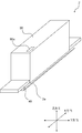
- 2 is a perspective view illustrating a schematic configuration of a liquid discharge head according to the present embodiment.
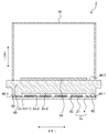
- FIG. FIG. 3 is a cross-sectional view in the longitudinal direction of the liquid ejection head according to the present embodiment.
- FIG. 6 is a cross-sectional view in the short direction of the liquid ejection head according to the present embodiment.
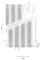
- A) is a top view which shows schematic structure of the head main body which concerns on this embodiment.
- (B) is a top view which shows schematic structure of the flow-path member which concerns on this embodiment. It is the figure which expanded area
- FIG. 1 is a schematic configuration diagram of a printer 1 according to the present embodiment.
- the printer 1 is a color inkjet printer, but is not limited thereto, and may be a recording apparatus such as a monochrome inkjet printer.
- the printer 1 includes a control unit 100, a paper feeding unit 114, a transport unit 120, a liquid ejection head 2, and a paper receiving unit 116.
- the liquid discharge head 2 and the transport unit 120 in the printer 1 are an embodiment of a recording apparatus according to the present invention.
- the control part 100 has a role which controls operation
- the arrangement of the control unit 100 is not particularly limited.
- the paper feed unit 114 has a paper storage case 115 and a paper feed roller 145.
- the paper storage case 115 has a role of storing a recording medium.
- a plurality of printing sheets P as recording media are stored in the sheet storage case 115 in a stacked state.
- the paper feed roller 145 has a role of feeding the printing paper P stored in the paper storage case 115 one by one toward the transport unit 120.
- two pairs of feed rollers 118a and 118b and 119a and 119b are arranged between the paper feed unit 114 and the transport unit 120 along the transport path of the printing paper P. .
- the printing paper P sent out from the paper supply unit 114 is guided by the feed rollers 118 a and 118 b and 119 a and 119 b and sent out to the transport unit 120.
- the transport unit 120 includes a transport belt 111, belt rollers 106 and 107, a transport motor 174, and nip rollers 138 and 139.
- the transport belt 111 has a role of transporting the printing paper P sent out from the paper storage case to the liquid ejection head 2.
- the conveyor belt 111 is wound around belt rollers 106 and 107.
- the conveyor belt 111 is stretched without slack along two parallel planes each including a common tangent to the belt rollers 106 and 107.
- the liquid ejection head 2 is disposed so as to face one of the two planes. Therefore, the surface of the transport belt 111 that faces the liquid ejection head 2 is a transport surface 127 for transporting the printing paper P.
- the transport motor 174 has a role of moving the transport belt 111.
- the conveyance motor 174 is connected to the belt roller 106.
- the transport motor 174 can rotate the belt roller 106 in the direction of arrow A.
- the belt roller 107 can rotate in conjunction with the transport belt 111. Therefore, the conveyor belt 111 can move along the direction of arrow A by rotating the belt roller 106 by the conveyor motor 174.
- the nip rollers 138 and 139 have a role of fixing the printing paper P on the transport surface 127.
- the nip rollers 138 and 139 are disposed opposite to each other with the conveyance surface 127 interposed therebetween.
- the nip rollers 138 and 139 rotate in conjunction with the movement of the conveyance belt 111.
- the printing paper P sent out from the paper supply unit 114 to the transport unit 120 is sandwiched between the nip roller 138 and the transport surface 127.
- the printing paper P is fixed on the conveyance surface 127 by being pressed against the conveyance surface 127 of the conveyance belt 111.
- the printing paper P is transported to the liquid ejection head 2 as the transport belt 111 moves.
- the liquid discharge head 2 has a role of discharging liquid onto the printing paper P.
- the liquid discharge head 2 is disposed so as to face the transport surface 127.
- the liquid discharge head 2 has a head body 2a.
- the head main body 2 a is located on the side close to the transport surface 127. The detailed configuration of the liquid discharge head 2 will be described later.
- droplets (ink) of four colors are ejected from the head body 2a.
- the four colors for example, magenta (M), yellow (Y), cyan (C), and black (K) can be employed.
- the printing paper P sent out from the paper supply unit 114 to the transport unit 120 passes through a gap between the liquid discharge head 2 and the transport surface 127 of the transport belt 111. At that time, droplets are ejected from the head body 2 a toward the printing paper P. As a result, a color image based on the image data stored by the control unit 100 is formed on the printing paper P. Further, the printing paper P on which the image is formed is sent out to the paper receiving unit 116.
- a separation plate 140, two pairs of feed rollers 121a and 121b, and 122a and 122b are disposed between the transport unit 120 and the paper receiver 116.
- the printing paper P on which the color image is printed is conveyed to the peeling plate 140 by the conveying belt 111.
- the printing paper P is sent out to the paper receiving unit 116 by the feed rollers 121a to 122b.
- the paper receiver 116 has a role of storing the printing paper P sent out from the transport unit 120.
- the paper receiver 116 is disposed in the transport direction of the printing paper P sent out from the transport unit 120.
- a paper surface sensor 133 is disposed between the liquid ejection head 2 and the nip roller 138.
- the paper surface sensor 133 has a role of detecting position information of the printing paper P conveyed on the conveyance surface 127.
- the paper surface sensor 133 includes, for example, a light emitting element and a light receiving element.
- the position information of the printing paper P detected by the paper surface sensor 133 is transmitted to the control unit 100.
- the control unit 100 controls the liquid ejection head 2 or the transport motor 174 based on the detection result received from the paper surface sensor 133. Thereby, the conveyance of the printing paper P and the printing of the image can be synchronized.
- FIG. 2 is a perspective view showing a schematic configuration of the liquid discharge head 2.
- FIG. 3 is a cross-sectional view in the longitudinal direction (X direction in FIG. 2) of the liquid ejection head 2 according to the present embodiment.
- 4 is a cross-sectional view of the liquid ejection head 2 in the short direction (Y direction in FIG. 2).
- the description of the flow paths in the flow path member 4 and the reservoir 40 is omitted for convenience of explanation.
- the liquid ejection head 2 includes a head body 2a, a reservoir 40, a first adhesive 50, a housing 90, a wiring board 94, a connector 95, a flexible wiring board 92, a driver IC 55, and a pressing plate 96. , And a heat insulating elastic member 97.
- the head main body 2a is located on the opposite side of the first main surface 2a-1 of the first main surface 2a-1 (discharge hole surface 4-1) of the head main body 2a in which the discharge holes 8 are disposed.
- the second main surface 2a-2 of 2a is included.
- the piezoelectric actuator substrate 21 is disposed on the second main surface 2a-2 side of the head body 2a.
- the head body 2a has a role of performing predetermined printing on the recording medium by discharging droplets from the discharge hole surface 2a-1 of the flow path member 4 in accordance with the displacement of the piezoelectric actuator substrate 21.
- the surface on which the discharge holes 8 are arranged is a discharge hole surface 4-1.
- a surface of the flow path member 4 opposite to the discharge hole surface 4-1 is a pressurizing chamber surface 4-2 where a pressurizing chamber 10 described later is disposed.
- the surface on which the discharge holes 8 are arranged is the first main surface 2a-1, which is the same surface as the discharge hole surface 4-1.
- the surface of the head body 2a opposite to the first main surface 2a-1 is a second main surface 2a-2.
- the second main surface 2 a-2 is a surface including the pressurizing chamber surface 4-2 that is not covered by the piezoelectric actuator substrate 21 and the main surface of the piezoelectric actuator substrate 21, and the thickness of the piezoelectric actuator substrate 21 is Therefore, the surface is uneven.
- the reservoir 40 serving as a supply unit has a role of supplying a liquid to the flow path member 4 of the head body 2a.
- the reservoir 40 is provided on the head body 2a.
- the reservoir 40 has a placement surface 40-1 and an upper surface 40-2.
- the mounting surface 40-1 is a part of the third main surface of the flow path member 4 that faces the pressurizing chamber surface 4-2 located on the opposite side of the discharge hole surface 4-1.
- the mounting surface 40-1 is bonded to the pressurizing chamber surface 4-2 through the first adhesive 50.
- the first adhesive 50 for example, a high temperature adhesive that cures under a temperature condition of 80 to 150 ° C. can be used.
- an epoxy resin can be used as the high temperature adhesive.
- the liquid supply path in the reservoir 40 that supplies liquid to the head main body 2a is a damper that can change the volume of the liquid supply path by deforming a part of its wall surface, and is discharged from the head main body 2a. When the amount of liquid changes abruptly, it may be possible to reduce fluctuations in the supply amount.
- the housing 90 has a role of accommodating each member included in the liquid ejection head 2.
- the housing 90 accommodates each member included in the liquid discharge head 2 so that at least the discharge hole surface 4-1 of the flow path member 4 included in the head body 2a is exposed.
- the housing 90 is provided on the reservoir 40. For this reason, as shown in FIG. 2, at least a part of the reservoir 40 and the head main body 2 a is exposed from the housing 90.
- the housing 90 has a housing opening 90a.
- the housing opening 90 a is provided by opening a part of the housing 90 located on the upper surface 40-2 of the reservoir 40.
- electric power can be supplied to the wiring board 94 or liquid can be supplied to the reservoir 40 through the housing opening 90 a.
- Examples of the constituent material of the housing 90 include a metal material or a resin material.
- the individual electrodes 25 on the piezoelectric actuator substrate 21 and the portions that electrically connect the individual electrodes 25 and the flexible wiring substrate 92 are sealed with the second adhesive 60, so that the housing 90 Is not necessarily required.
- the wiring board 94 has a role of receiving a drive signal transmitted from the control unit 100 when the liquid ejection head 2 is incorporated in the printer 1.
- the wiring board 94 is provided on the upper surface 40-2 of the reservoir 40.
- a connector 95 is mounted on the wiring board 94.
- the wiring substrate 94 for example, a substrate provided with various electronic components on a resin substrate or a ceramic substrate can be used.
- the flexible wiring board 92 has a role of electrically connecting the piezoelectric actuator substrate 21 and the connector 95.
- a driver IC 55 is mounted on the flexible wiring board 92.
- the flexible wiring board 92 for example, a conventionally known flexible printed wiring board can be used.
- the wiring board 94 transmits the drive signal received from the control unit 100 to the flexible wiring board 92.
- the driver IC 55 mounted on the flexible wiring board 92 performs a predetermined process on the drive signal and transmits the processed drive signal to the piezoelectric actuator board 21.
- the piezoelectric actuator substrate 21 is displaced in accordance with the drive signal after the processing, thereby ejecting droplets from the ejection hole surface 4-1 of the flow path member 4. In this way, predetermined printing can be performed on the recording medium by the droplets ejected from the ejection hole surface 4-1.
- the number of wiring boards 94 and driver ICs 55 mounted is not particularly limited, and can be appropriately changed according to the usage mode of the liquid ejection head 2. Further, the wiring board 94 may not be provided. For example, the control unit 100 and the flexible wiring board 92 may be directly electrically connected.
- the pressing plate 96 has a role of pressing the driver IC 55 against the housing 90.
- the pressing plate 96 is provided on the reservoir body 40.
- a heat insulating elastic member 97 is attached to the pressing plate 96.
- the pressing plate 96 presses the driver IC 55 against the housing 90 via the heat insulating elastic member 97 and the flexible wiring board 92. For this reason, the heat generated in the driver IC 55 can be transmitted to the housing 90. Therefore, the heat can be radiated to the outside of the liquid discharge head 2.
- the constituent material of the housing 90 is preferably a material having a relatively high thermal conductivity.
- the constituent material of the housing 90 is preferably, for example, a metal material.
- the flexible wiring board 92 is curvedly arranged in the housing 90. For this reason, a force is applied to the flexible wiring board 92 to return from the curved state to the steady state.
- the driver IC 55 is strongly pressed by the housing 90 by the force. Therefore, the heat generated in the driver IC 55 is easily transmitted by the housing 90.
- FIG. 5A is a plan view showing a schematic configuration of the head main body 2a.
- FIG. 5B is a plan view showing a schematic configuration of the flow path member 4.
- a region where the piezoelectric actuator substrate 21 is located is indicated by a one-dot chain line.
- the illustration of the first through hole 60 is omitted for convenience of explanation.
- FIG. 6 is an enlarged view of a region A1 surrounded by a two-dot chain line shown in FIG. Note that the pressurizing chamber 10 and the individual flow path 12 shown in FIG. 6 are indicated by solid lines for convenience of explanation.
- 7 is a cross-sectional view taken along the line II shown in FIG.
- the head body 2 a has a piezoelectric actuator substrate 21 and a flow path member 4.
- the head main body 2a has a substantially rectangular shape extending in the X direction in plan view, but is not limited to this, and can be changed as appropriate according to the usage mode of the liquid ejection head 2.
- the piezoelectric actuator substrate 21 has a substantially trapezoidal shape in plan view. As shown in FIG. 6, in the present embodiment, the piezoelectric actuator substrate 21 has a trapezoidal acute angle cut off in plan view. For this reason, the piezoelectric actuator substrate 21 has a hexagonal shape in plan view, but since the side corresponding to the acute angle cut off is very short compared to the other sides, it can be formed into a substantially trapezoidal shape.
- Four piezoelectric actuator substrates 21 are provided on the pressure chamber surface 4-2 of the flow path member 4. Specifically, the four piezoelectric actuator substrates 21 are provided side by side in two rows along the X direction. Of the two piezoelectric actuator substrates 21 adjacent to each other, the opposite hypotenuses are positioned so as to overlap each other in the Y direction.
- the placement region E1 that overlaps the placement surface 40-1 of the reservoir 40 in the pressurizing chamber surface 4-2 of the flow path member 4 is indicated by a one-dot chain line.
- Two placement areas E1 are provided at both ends in the X direction of the pressurizing chamber surface 4-2 and four corresponding to the four piezoelectric actuator substrates 21.
- the placement region E1 corresponding to the piezoelectric actuator substrate 21 is located side by side with the piezoelectric actuator substrate 21 in the Y direction.
- the placement region E1 corresponding to the piezoelectric actuator substrate 21 is located opposite to the short side of the substantially trapezoidal piezoelectric actuator substrate 21 in plan view.
- the four piezoelectric actuator substrates 21 are located in a space between the pressurizing chamber surface 4-2 of the flow path member 4 and the reservoir 40 outside the placement region E1.
- the planar view shape or the number of the piezoelectric actuator substrates 21 is arbitrary, and can be appropriately changed according to the usage mode of the liquid discharge head 2.
- the number of the piezoelectric actuator substrates 21 may be one, and may have a substantially rectangular shape smaller than the second main surface 2a-2 of the head body 2a in plan view.
- two placement areas E1 are provided at both ends in the X direction of the second main surface 2a-2 of the head body 2a, and the piezoelectric actuator substrate 21 is disposed between the two placement areas E1. can do.
- the piezoelectric actuator substrate 21 may be provided on a surface other than the pressurizing chamber surface 4-2 of the flow path member 4, so that each of the plurality of pressurizing chambers 10 can be pressurized. It only has to be configured.
- the piezoelectric actuator substrate 21 has piezoelectric ceramic layers 21a and 21b, common electrodes 24, individual electrodes 25, connection electrodes 26, dummy connection electrodes 27, and a common electrode surface electrode 28.
- the piezoelectric ceramic layer 21a has a role as a diaphragm.
- the piezoelectric ceramic layer 21a covers a plurality of holes formed in the cavity plate 4a on the pressure chamber surface 4-2.
- the plurality of holes covered with the piezoelectric ceramic layer 21 a are holes constituting the pressurizing chamber 10. That is, the plurality of pressurizing chambers 10 are formed so as to be surrounded by the piezoelectric ceramic layer 21a and the cavity plate 4a.
- the common electrode 24 is provided on substantially the entire surface of the piezoelectric ceramic layer 21a.
- the piezoelectric ceramic layer 21 b is provided on substantially the entire surface of the common electrode 24.
- a plurality of individual electrodes 25 are provided corresponding to the pressurizing chamber 10 on the piezoelectric ceramic layer 21b. Specifically, the individual electrode 25 has an individual electrode main body 25 a disposed so as to overlap the pressurizing chamber 10 in a plan view, and a lead electrode 25 b disposed so as not to overlap the pressur
- the common electrode 24 is electrically connected to the flexible wiring substrate 92 via a common electrode surface electrode 28 (not shown) provided on the piezoelectric ceramic layer 21b.
- the individual electrode main body 25a is electrically connected to the flexible wiring board 92 via the connection electrode 26 provided on the lead electrode 25b.
- the dummy electrode 27 is provided on the piezoelectric ceramic layer 21b.
- Examples of the constituent material of the piezoelectric ceramic layers 21a and 21b include lead zirconate titanate or barium titanate.
- Examples of constituent materials of the common electrode 24, the individual electrode 25, the connection electrode 26, the dummy connection electrode 27, and the common electrode surface electrode 28 include Au, Ag, Pd, Ag-Pd, Pt, Ni, and Cu.
- Examples of the method for forming the piezoelectric actuator substrate 21 include the following methods. That is, a tape made of a piezoelectric ceramic powder and an organic composition is formed by a tape forming method such as a roll coater method or a slit coater method, and a plurality of green sheets that become piezoelectric ceramic layers 21a and 21b after firing are produced.
- an electrode paste to be the common electrode 24 is formed on the surface of the green sheet by a printing method or the like. Further, a via hole is formed in a part of the green sheet, and a via conductor is filled in the via hole. Then, each green sheet is laminated
- the channel member 4 has a laminated structure in which a plurality of plates are laminated as shown in FIG.
- the flow path member 4 is configured by sequentially laminating a cavity plate 4a, a base plate 4b, an aperture plate 4c, a supply plate 4d, manifold plates 4e to g, a cover plate 4h, and a nozzle plate 4i.
- the lower surface of the nozzle plate 4 i is a discharge hole surface 4-1 on which the discharge holes 8 are provided.
- the upper surface of the cavity plate 4a is a pressurizing chamber surface 4-2 on which the piezoelectric actuator substrate 21 is disposed.
- each plate 4a to i for example, a metal material, stainless steel, or silicon can be cited.
- examples of the constituent material of the nozzle plate 4i include stainless steel, nickel, polyimide, and silicone.
- the flow path member 4 is formed, for example, by bonding the plates 4a to 4i to each other via a high temperature adhesive (not shown) that is cured at a temperature of 80 to 150 ° C.
- Examples of the high temperature adhesive include those similar to the first adhesive 50.
- the thickness of each plate 4a to i can be set to 10 to 300 ⁇ m, for example.
- each plate 4a-i a large number of holes are formed in each plate 4a-i.
- the manifold 5, the individual flow path 12, the discharge hole 8, and the first through hole 7 are configured by the holes.
- the holes are formed, for example, by etching a predetermined portion of each plate 4a to i.
- the manifold 5 has a role of supplying a liquid to the individual flow path 12.
- the manifold 5 is configured by communicating a plurality of holes formed in each of the plates 4a to 4g.
- a supply hole 5a for supplying a liquid to the flow path member 4 is provided in the second main surface 2a-2 of the head body 2a.
- a plurality of supply holes 5a exist in the placement region E1 of the placement surface 40-1 of the reservoir 40. That is, the liquid is supplied to the flow path member 4 from a liquid supply path of the reservoir 40 (not shown) through the supply hole 5a in the placement region E1.
- the plurality of supply holes 5a communicate with holes formed in the manifold plates 4e to 4h via holes formed in the respective plates 4a to 4d.
- the holes formed in the manifold plates 4e to 4h constitute a main flow path of the manifold 5, and branch and extend into a plurality of flow paths in the X direction.
- the plurality of supply holes 5a communicate with each other through the plurality of flow paths.
- the individual flow path 12 is a flow path that guides the liquid supplied from the manifold 5 to the discharge hole 8.
- the individual flow path 12 refers to a flow path that communicates from the manifold 5 to the discharge hole 8 via the individual supply path 14, the aperture 6, and the pressurizing chamber 10.
- the individual supply path 14 is configured by a hole formed in the supply plate 4d.
- a plurality of individual supply paths 14 are provided.
- Each of the plurality of individual supply paths 14 communicates with the manifold 12. For this reason, the liquid accommodated in the manifold 5 is individually supplied to the plurality of discharge holes 8 via the plurality of individual supply paths 14.
- the squeezing 6 has a role of reducing the possibility that the liquid stored in the pressurizing chamber 10 flows backward to the manifold 5 when the pressurizing chamber 10 is pressurized. For this reason, the cross-sectional area of the flow path in the squeezing 6 is smaller than the cross-sectional area of the flow path communicating the pressurizing chamber 10 and the discharge hole 8.
- the squeezing 6 is configured by a hole formed in the aperture (squeezing) plate 4c.
- the restrictor 6 communicates with the individual supply path 14. For this reason, a plurality of the squeezing 6 are provided corresponding to each of the plurality of individual supply paths 14.
- the pressurizing chamber 10 has a role of supplying the liquid stored in the pressurizing chamber 10 to the discharge hole 8 by being pressurized by the piezoelectric actuator substrate 21.
- the pressurizing chamber 10 is configured by holes formed in the cavity plate 4a.
- the pressurizing chamber 10 is disposed so as to overlap the individual electrode main body 25a in plan view. More specifically, all parts of the individual electrode main body 25a are located in a region where the pressurizing chamber 10 is located in a plan view. In FIG. 6, only a part of the individual electrode main body 25a is shown for convenience of explanation. Further, the pressurizing chamber 10 communicates with the aperture 6 through a hole in which the base plate 4b is formed. For this reason, a plurality of pressurizing chambers 10 are provided corresponding to each of the plurality of apertures 6.
- the pressurizing chamber 10 has a substantially rhombus shape with rounded corners in plan view.
- the plurality of pressurizing chambers 10 are arranged in a staggered manner.
- the plurality of pressurizing chambers 10 are arranged in a row along the X direction.
- 16 pressurizing chambers arranged in a row along the X direction are arranged in 16 rows in the Y direction.
- the discharge hole 8 has a role of discharging the liquid supplied from the pressurizing chamber 10 to the outside.
- the discharge hole 8 is configured by opening a hole formed in the nozzle plate 4i on the discharge hole surface 4-1.
- the discharge hole 8 communicates with the pressurizing chamber 10 through a plurality of holes formed in the base plate 4b, the aperture plate 4c, the supply plate 4d, the manifold plates 4e to 4g, the cover plate 4h, and the nozzle plate 4i. is doing. For this reason, a plurality of discharge holes 8 are provided corresponding to each of the plurality of pressurizing chambers 10.
- the number and arrangement of the plurality of pressurizing chambers 10 and the discharge holes 8 are arbitrary, and can be appropriately changed according to the usage mode of the liquid discharge head 2.
- the piezoelectric ceramic layer 21b is displaced according to the drive signal sent from the flexible wiring board 92 to the common electrode 24 and the individual electrode 25.
- the piezoelectric ceramic layer 21a is curved toward the pressurizing chamber 10 according to the displacement of the piezoelectric ceramic layer 21b, thereby applying a predetermined pressure to the pressurizing chamber 10. Thereby, the liquid accommodated in the pressurizing chamber 10 is discharged from the discharge hole 8.
- the flow path member 4 further has a first through-hole 7 provided by communicating holes formed in the cavity plate 4a and the base plate 4b.
- a first through-hole 7 provided by communicating holes formed in the cavity plate 4a and the base plate 4b.
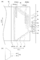
- FIG. 8A is a plan view showing a connection structure between the piezoelectric actuator substrate 21 and the flexible wiring substrate 92. 8A, only one piezoelectric actuator substrate 21, the flexible wiring substrate 92 corresponding to the piezoelectric actuator substrate 21, the flow path member 4, and the second adhesive material 60 are illustrated for convenience of explanation.
- FIG. 8B is a plan view of the first region in the same region as FIG. 9 is a cross-sectional view taken along the line II-II shown in FIG. 8A, and illustrates the first adhesive 50 and the reservoir 40 in addition to the members shown in FIG. 8A.
- the flexible wiring board 92 is positioned so as to cover one piezoelectric actuator board 21 in plan view.
- four flexible wiring boards 92 are provided corresponding to the four piezoelectric actuator substrates 21, but not limited to this, one flexible wiring substrate 92 is provided corresponding to the four piezoelectric actuator substrates 21. It may be.
- the flexible wiring board 92 does not overlap the placement area E1 in plan view.
- the flexible wiring board 92 has a plurality of lands 92a.
- the plurality of lands 92 a are electrically connected to each of the plurality of individual electrodes 25. Specifically, the plurality of lands 92 a are connected to the connection electrode 26 provided on the extraction electrode 25 b of the individual electrode 25.
- the plurality of lands 92 a are connected to a plurality of wirings (not shown) included in the flexible wiring board 92, and the plurality of wirings are connected to the wiring board 94. In this way, the flexible wiring board 92 supplies a drive signal to each of the plurality of individual electrodes 25.
- the second adhesive 60 is provided between the second main surface 2a-2 of the head body 2a (more specifically, the pressure chamber surface 4-2 of the flow path member 4) and the flexible wiring board 92. It has been.
- the second adhesive 60 bonds the second main surface 2a-2 of the head body 2a and the flexible wiring board 92 to each other.
- the second adhesive 60 is positioned so as to surround the piezoelectric actuator substrate 21 in plan view.
- the surface of the head body 2a surrounded by the second adhesive 60 is defined as a first region E2
- the surface of the head body 2a other than the first region E2 is defined as a second region E3.
- the plurality of individual electrodes 25 are located in a space S ⁇ b> 1 surrounded by the first region E ⁇ b> 2, the flexible wiring substrate 92, and the second adhesive material 60. For this reason, for example, when the liquid enters the second main surface 2a-2 of the head body 2a from between the housing 90 and the flow path member 4 or along the inner wall of the housing 90, the liquid The possibility of contact with the plurality of individual electrodes 25 can be reduced. And since the some individual electrode 25 faces space S1, the displacement at the time of applying a voltage is hard to be suppressed by the 2nd adhesive material 60. FIG.
- the second adhesive 60 bonds the pressure chamber surface 4-2 and the flexible wiring board 92, but not limited to this, the piezoelectric actuator substrate 21 and the flexible wiring board 92 are bonded together. It may be adhered.
- the second adhesive 60 is surrounded.
- the second adhesive 60 in plan view, is disposed to a position closer to the plurality of individual electrodes 25 than in the present embodiment, and the space S1 is the pressure chamber surface 4- 2 and is connected to the first through-hole 7 opened to the pressurizing chamber surface 4-2 at the drawn-out tip.
- the second adhesive 60 is disposed on the piezoelectric actuator substrate 21 in plan view, and the space S1 is connected to the first through hole 7 opened in the piezoelectric actuator substrate 21.
- the first through hole 7 that penetrates the piezoelectric actuator substrate 21 penetrates the piezoelectric actuator substrate 21 in the Z direction and is connected to the first through hole 7 that penetrates the flow path member 4. Good.
- the first through hole 7 penetrating the piezoelectric actuator substrate 21 advances in the Z direction toward the flow path member 4 and then advances in the plane direction (X direction, Y direction, or a direction between them).
- the plane direction X direction, Y direction, or a direction between them.
- the first through-hole 7 extending in the planar direction may be provided inside the piezoelectric actuator substrate 21, or the groove or flow of the piezoelectric actuator substrate 21 located at the boundary between the piezoelectric actuator substrate 21 and the flow path member 4.
- the groove of the path member 4 or a combination of these grooves may be used.
- the second adhesive 60 surrounds the plurality of individual electrodes 25 in plan view, the possibility that the plurality of individual electrodes 25 and the liquid come into contact with each other is reduced. be able to.
- the second adhesive 60 for example, a silicone resin or an epoxy resin can be used.
- the second adhesive 60 for example, an adhesive mainly composed of phenol resin, urea resin, melamine resin, or the like can be used.
- a method for forming the second adhesive 60 for example, a method of applying using a dispenser, a method of transferring to the pressurizing chamber surface 4-2 by screen printing, a pressurizing chamber surface 4 after preliminarily applying to the flexible wiring board 92. -2 and the like.
- the amount of the second adhesive 60 is present. Since the surrounding rigidity is different from the surrounding rigidity of the other pressurizing chambers 10, the state of vibration may be different.
- the distance between the pressurizing chamber 10 closest to the second adhesive 60 and the second adhesive 60 is the diameter obtained by converting the area of the pressurizing chamber 10 into a circle (the same area as the pressurizing chamber 10 area). If it is more than the diameter of the circle having
- the pressurizing chamber 10 may include a pressurizing chamber 10 that is actually used for discharging and a dummy pressurizing chamber 10 that is not used for discharging.
- the dummy pressurizing chamber 10 is used for discharging in order to bring the rigidity around the pressurizing chamber 10 arranged on the outermost side among the pressurizing chambers 10 used for discharging to be close to other pressurizing chambers 10. It is arranged further outside the pressurizing chamber 10. It is the pressurizing chamber 10 used for discharge among the pressurizing chambers 10 that needs to have the distance from the second adhesive 60 as described above. It is not necessary to satisfy the conditions.
- the second adhesive 60 is arranged outside the main surface of the piezoelectric actuator substrate 21 so that the second adhesive 60 does not spread to the position where the pressurizing chamber 10 exists due to variations in the manufacturing process. It is preferable to do this. By doing so, since the side surface of the piezoelectric actuator substrate 21 rises from the pressurizing chamber surface 4-2, the second adhesive 60 is made the main surface of the piezoelectric actuator substrate 21 by the side surface of the piezoelectric actuator substrate 21. It can be difficult to invade.
- the second adhesive 60 may be a resist for the flexible wiring board 92.
- the flexible wiring board 92 is provided with wirings electrically connected to the lands 92a, and the wirings are arranged between two resist layers in order to suppress a short circuit between them.
- the resist on the piezoelectric actuator substrate 21a side is open, so that the land 92a and the individual electrode 25 can be electrically joined.
- the resist on the piezoelectric actuator substrate 21a side of the flexible wiring substrate 92 is applied in an uncured state, and the flexible wiring substrate 92 and the head main body 2a are bonded with the uncured resist, and then the resist is cured and bonded. You just need to strengthen it.
- the bonding is performed so that corners on the outer periphery of the piezoelectric actuator substrate 21 bite into the resist (more preferably, penetrate through the uncured resist).
- the corners on the outer periphery continuous protrusions are provided on the head body 2a so as to surround the plurality of individual electrodes 25, and the protrusions bite into the resist (more preferably through the uncured resist). You may do it.
- a protrusion for example, if a resin containing silver particles is used, the land 92a and the individual electrode 25 can be prevented by the protrusion.
- the protrusion may be provided with an opening in the resist in advance and electrically rusted with the land 92a.
- the protrusion may penetrate the uncured resist, and then the resist may be cured. And the protrusions may be physically connected.
- the head main body 2a has the first through holes 7.
- the first through hole 7 is provided independently of the individual flow path 12.
- the first through hole 7 has a first opening 7a and a second opening 7b.
- the first opening 7a is open in the first region E2.
- the flexible wiring substrate 92 and a part of the second adhesive 60 protrude so as to be aligned with the placement region E1 in the X direction.
- the first opening 7a is open in a first region E2 that overlaps the protruding flexible wiring board 92 in plan view.
- the first opening 7a is provided side by side with the placement region E1 in the X direction.
- the second opening 7b is open in the second region E3.
- the second opening 7b opens in the placement region E1 that the pressurizing chamber surface 4-2 has.
- the second opening 7b is located between the supply hole 5a and the first opening 7a in the X direction.
- the space S1 communicates with the outside of the flow path member 4 via the first opening 7a and the second opening 7b of the first through hole 7. For this reason, possibility that a malfunction will arise in the piezoelectric actuator board
- substrate 21 can be reduced.
- the first opening 7 a is arranged outside the region having the outer edge of the individual electrode 25 arranged on the outermost side among the plurality of individual electrodes 25 surrounded by the second adhesive 60.
- the distances between the individual electrodes 25 can be arranged without greatly separating them, so that the distances between the ejection holes 8 can be arranged without greatly separating them, whereby the liquid ejection head 2.
- the decrease in recording accuracy when the installation angle of the recording medium is shifted can be reduced.
- the first region E2 includes a third region E4 that includes all of the plurality of individual electrodes 25 surrounded by the second adhesive 60, and a fourth region that protrudes from the third region E4. E5 is included, and the first opening 7a is disposed in the fourth region E5.
- the area of the first region E2 increases, the volume of the space S1 increases, and the volume change amount of the gas in the space S1 when the temperature changes also increases. It is preferable to reduce the area of the first region E2 so that the second adhesive 60 does not peel off due to the volume change. And in order not to suppress the displacement by the individual electrode 25, what is necessary is just to make the 1st area
- the piezoelectric actuator substrate 21 is not provided with the first through hole 7, and the first through hole 7 is provided only in the flow path member 4 and the first opening 7 a is disposed in the flow path member 4. .
- the piezoelectric actuator substrate 21 is preferably a ceramic sintered body.
- the first through hole 7 is preferably provided only in the flow path member 4 and the first opening 7 a is disposed in the flow path member 4.
- the fourth region E5 has a shape protruding to the outside of the piezoelectric actuator substrate 21.
- the second opening 7b is preferably opened in a portion other than the first main surface 2a-1 of the head body 21. Since the first main surface 2a-1 has a part of the discharged liquid as mist, the second opening 7b is arranged in a portion other than the first main surface 2a-1, so that the first through hole 7a is disposed. It becomes difficult for mist to enter.
- the second opening 7b is preferably arranged on the second main surface 2a-2 of the head body 2a. In this case, the mist generated on the first main surface 2a-1 does not reach the second opening 7b unless it moves around the side surface of the head body 2a. It becomes difficult for mist to enter. In addition, since the moving distance until the mist reaches the second opening 7b becomes long, the mist hardly enters the first through hole 7.
- the flow path member 4 is formed, for example, by thermocompression bonding the plurality of plates 4a to i via an adhesive.
- the piezoelectric actuator substrate 21 and the flow path member 4 are thermocompression bonded to each other through an adhesive, for example. That is, heat may be applied to the piezoelectric actuator substrate 21 during the manufacturing process of the head body 2a. Further, heat may be generated in the piezoelectric actuator substrate 21 in the process of using the liquid discharge head 2, or heat may be transmitted from other parts of the liquid discharge head 2 or from the outside of the liquid discharge head 2. Thus, when heat is applied to the piezoelectric actuator substrate 21 during the manufacturing process or the use process of the liquid discharge head 2, the air in the space S1 may expand.
- the space S ⁇ b> 1 is completely sealed.
- stress is applied to the flexible wiring board 92 due to the expansion of air in the space S1, and the flexible wiring board 92 is peeled off from the second main surface 2a-2 of the head body 2a.
- the flexible wiring substrate 92 is peeled off from the second main surface 2a-2 of the head body 2a, the liquid that has entered between the flexible wiring substrate 92 and the pressurizing chamber surface 4-2 comes into contact with the plurality of individual electrodes 25. As a result, a problem may occur in the piezoelectric actuator substrate 21.
- the electrical connection between the individual electrode 25 and the land 92a may be peeled off.
- a temperature of about 100 to 200 ° C. (or higher in some cases) is applied, whereas the temperature in the use process is Since it is about 60 ° C. at the highest, it is highly necessary to cope with the temperature of the manufacturing process. Therefore, the first through hole may be closed after the manufacturing process in which a high temperature (for example, 100 ° C. or higher) is applied is finished.
- the head body 2 a has the first through hole 7.
- the first through hole 7 communicates the space S1 and the outside of the head body 2a. That is, since an air moving path is provided between the space S1 and the outside of the head main body 2a, the possibility of air expanding in the space S1 can be reduced. For this reason, it is possible to reduce the possibility that the flexible wiring board 92 is peeled off from the second main surface 2a-2 of the head body 2a due to the stress applied to the flexible wiring board 92. Therefore, it is possible to reduce the possibility that a problem occurs in the piezoelectric actuator substrate 21 due to contact between the liquid and the plurality of individual electrodes 25.
- the first opening 7a and the second opening 7b are preferably opened on the pressurizing chamber surface 4-2. That is, the first opening 7a and the second opening 7b are preferably opened in the same plane. According to such a configuration, even if a liquid enters the first through hole 7 from the second opening 7b, the possibility that the liquid reaches the space S1 can be reduced. For this reason, possibility that a liquid and the some individual electrode 25 will contact can be reduced more.
- each of the four piezoelectric actuator substrates 21 exists in one liquid discharge head 2, and each of the four piezoelectric actuator substrates 21 is present on one piezoelectric actuator substrate 21.
- the single space S1 is arranged so as to seal the individual electrodes 25, but other modes may be used.
- the number of piezoelectric actuator substrates 21 may be other numbers including one.
- a plurality of spaces S1 may be arranged for one piezoelectric actuator substrate 21.
- the individual electrodes 25 may be arranged in a plurality of groups, and each group may be surrounded by the second adhesive 60 and the space S1 may be arranged in each group.
- the space S ⁇ b> 1 may be disposed across the plurality of piezoelectric actuator substrates 21. Furthermore, when a plurality of spaces S1 are arranged in one liquid ejection head 2, the through-hole connected to one part of the space S1 is not directly connected to the outside, and the other space S1 and its space You may connect with the exterior through the 1st through-hole 7 connected with space S1.
- the second opening 7b is preferably located in the placement area E1. In other words, it is preferable that the second opening 7 b overlaps with the mounting surface 40-1 of the reservoir 40. According to such a configuration, even when the liquid enters the pressurizing chamber surface 4-2, the possibility that the liquid enters the placement region E1 can be reduced. That is, the possibility of liquid entering the second opening 7b can be reduced.
- the first opening 7a is preferably provided side by side with the placement area E1. According to such a configuration, the separation distance between the first opening 7a and the second opening 7b can be relatively reduced. For this reason, the ratio of the 1st through-hole 7 to the whole flow-path member 4 can be made small. Therefore, it is possible to reduce the possibility that the formation of the individual flow path 12 is hindered by the presence of the first through hole 7.
- the reservoir 40 preferably has a second through hole 41 provided from the placement surface 40-1 to the upper surface 40-2.
- the second through hole 41 has a third opening 41a that opens on the mounting surface 40-1, and a fourth opening 41b that opens on the upper surface 40-2.
- the third opening 41a overlaps the second opening 7b.
- the reservoir 40 is bonded onto the pressure chamber surface 4-2 of the flow path member 4 via the first adhesive 50.
- the mounting surface 40-1 of the reservoir 40 is thermocompression bonded onto the mounting region E 1 of the flow path member 4 via the first adhesive 50. That is, in the bonding process between the reservoir 40 and the flow path member 4, heat may be applied to the piezoelectric actuator substrate 21. Therefore, in the present embodiment, the reservoir 40 has a second through hole 41.
- the third opening 41a overlaps with the second opening 7b. That is, the second through hole 41 communicates with the first through hole 7. For this reason, the space S ⁇ b> 1 communicates with the outside of the flow path member 4 and the reservoir 40 via the first through hole 7 and the second through hole 41.
- the reservoir 40 is provided with a liquid supply path communicating with the supply hole 5 a of the manifold 5 in addition to the second through hole 41.
- the reservoir 40 is configured by stacking a plurality of plates, for example, like the flow path member 4.
- the second through hole 41 and the liquid supply path are configured by communicating holes formed in a plurality of plates. Examples of the plurality of plates include those similar to the flow path member 4.
- the fourth opening 41b is opened in the upper surface 40-2.
- the upper surface 40-2 is a surface located on the opposite side of the placement surface 40-1. That is, the upper surface 40-2 is a surface located on a side relatively far from the pressurizing chamber surface 4-2.
- the pressurizing chamber surface 4-2 is a surface into which liquid easily enters, for example, between the housing 90 and the flow path member 4 or along the inner wall of the housing 90.
- the fourth opening 41b opens at the upper surface 40-2, the possibility of liquid intrusion into the fourth opening 41b can be reduced. For this reason, it is possible to reduce the possibility of liquid entering the space S ⁇ b> 1 via the second through hole 41 and the first through hole 7.
- the second through hole 41 preferably has a first part 41c, a second part 41d, and a third part 41e.
- the first part 41c is a part extending from the third opening 41a to the upper surface 40-2 side.
- the second part 41d is a part extending from the fourth opening 41b to the placement surface 40-1.
- the third part 41e is a part that connects the end of the first part 41c and the end of the second part 41d.
- the region where the third part 41e is located is surrounded by a one-dot chain line.
- the end of the first part 41c is located on the upper surface 40-2 side than the end of the second part 41d.
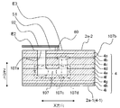
- FIG. 10 is a longitudinal sectional view of a head main body 2a used in a liquid discharge head 2 according to another embodiment of the present invention.
- the basic configuration of the head main body 2a is the same as that shown in FIGS. 2 to 8, and parts having little difference are denoted by the same reference numerals and description thereof is omitted.
- FIG. 10 is a longitudinal sectional view in a direction that is 90 degrees different from the longitudinal sectional view shown in FIG.
- the first through-hole 107 has a first opening 107a that opens on the second main surface 2a-2 of the head main body 2a and a second opening that opens on the side surface of the head main body 2a.
- the opening 107b is connected.
- the first through hole 107 is formed in order from the first opening 107a through the holes of the plates 4a, 4b, 4c, and 4d, toward the first main surface 2a-1 side in the Z direction, and through the through groove of the plate 4e in the X direction.
- the plate 4b comprises the squeeze 6, the thickness is thin, and the ratio of the length with respect to the cross section of the through-hole of the part is large. Since the first through-hole 107 includes the groove of the plate 4b, the first through-hole 107 becomes elongated and the mist easily attaches to the inner wall in the middle.
- the temperature change applied to the liquid discharge head 2 is larger in the manufacturing process than in the process of using the liquid discharge head 2, and the volume change of the gas in the space S ⁇ b> 1 (to be precise, the volume change that does not increase the volume of the space S ⁇ b> 1 Is a pressure change), but the manufacturing process is larger. For this reason, problems such as peeling of the second adhesive 60 are more likely to occur in the manufacturing process. Therefore, the second opening 107b may be closed after a process having a large temperature change in the manufacturing process is completed as long as the temperature change in the use process can be tolerated.
- the mist of the discharged liquid may enter.
- the temperature drops to room temperature after the temperature rises during the use process, if there is mist around the mist, the mist may be sucked into the first through hole 107 due to the volumetric contraction of the gas in the space S1.
- the volume ratio with the gas at room temperature of 25 ° C. is (273 + 60) / (273 + 25) ⁇ 1.12. Therefore, if the volume of the first through-hole 107 with respect to the volume of the space S1 is 12% or more, the gas that has entered from the outside does not reach the first opening 107a even when the temperature falls from 60 ° C.
- the entry of foreign matter can be controlled by controlling the cleanliness of the environment, but if the processing temperature is considered to be up to about 200 ° C., the volume ratio to the gas at room temperature of 25 ° C. is (273 + 200). ) / (273 + 25) ⁇ 1.59, the volume of the first through-hole 107 relative to the volume of the space S1 may be 59% or more.
- the second through hole 41 is connected to the first through hole 107.
- the total volume of the first through hole 107 and the second through hole 41 with respect to the volume of the space S1 may be 12% or more, further 18% or more, and particularly 59% or more.
- the mist that has entered the first through hole 107 moves randomly. If the 1st through-hole 107 is elongate, possibility that mist will adhere to the inner wall of the 1st through-hole 107 will increase rather than advancing along the 1st through-hole 107. FIG. If the ratio of the length to the width of the first through hole 107 is five times higher, it is difficult for mist that moves randomly to reach the first opening 107a from the second opening 107b. The ratio of length to width is more preferably 10 times higher.
- the diameter obtained by converting the cross-sectional area into a circle may be the ratio of the length to the width (L / R).
- a value obtained by dividing the volume of the first through-hole 107 by the length of the first through-hole 107 may be similarly calculated as an average cross-sectional area.
- the first through hole 107 has three corner portions 107c bent at an angle of 90 degrees or less.
- the first through hole 107 has a folded portion 107d in which the direction from the second opening 107b toward the first opening 207a along the first through hole 107 changes in the opposite direction. That is, the direction to enter the folded portion 107d is opposite to the direction to exit the folded portion 107d.
- the traveling direction must be reversed during that time, so that there is a high possibility that the mist will adhere to the inner wall and reach the first opening 107b. Can be lowered.
- any of the direction entering the folded portion 107d and the direction exiting the folded portion 107d is a direction opposite to the gravity, the mist is difficult to move against the gravity, and thus may reach the first opening 107b. Can be lowered. If there are a plurality of folded portions 107d and the first through-hole 107 has a meandering shape, the possibility of reaching the first opening 107b can be further reduced.
- FIG. 11 is an enlarged plan view of a head main body 2a used in the liquid discharge head 2 according to another embodiment of the present invention. Since the basic configuration of the head main body 2a is the same as that shown in FIGS. 2 to 8, parts with little difference are given the same reference numerals and description thereof is omitted. FIG. 11 is an enlarged plan view of the same portion as FIG.
- a ground electrode 28 is disposed on the main surface of the piezoelectric actuator substrate 21 of FIG.
- the ground electrode 28 is electrically connected to the common electrode 24 via a via hole conductor (not shown) that penetrates the piezoelectric ceramic layer 21b.
- the ground electrode 28 is electrically connected to the land 92a of the flexible wiring board 92 via a connection portion (not shown).
- the drive signal is sent to each individual electrode 25 as a voltage based on the ground electrode 28 held at the ground.
- the ground electrode 28 is disposed outside the region where the individual electrode 25 is disposed.
- the second adhesive 60 is disposed in the portion where the ground electrode 28 is disposed, and the connection portion is embedded in the second adhesive 60.
- the connection by the connecting portion reinforces the adhesion between the flexible wiring board 92 and the head main body 2a by the second adhesive 60, and the second adhesive 60 can be prevented from peeling off.
- Some of the intervals between the plurality of individual electrodes 25 arranged on one piezoelectric actuator substrate 21 may be larger than the other intervals.
- the groups are separated from each other so that color mixture between the ejection holes 8 on the ejection hole surface 4-1 is difficult to occur.
- the first through hole 7 is provided so as to penetrate the piezoelectric actuator substrate 21.
Landscapes
- Particle Formation And Scattering Control In Inkjet Printers (AREA)
Abstract
Description
印刷用紙Pの搬送と画像の印刷とを同期させることができる。
E3 第2領域
E4 第3領域
E5 第4領域
S1 空間
1 プリンタ(記録装置)
2 液体吐出ヘッド
2a ヘッド本体
2a-1 ヘッド本体の第1主面(吐出孔面)
2a-2 ヘッド本体の第2主面 4 流路部材
4-1 吐出孔面(流路部材の第1主面)
4-2 加圧室面
7、107 第1貫通孔
7a、107a 第1開口部
7b、107b 第2開口部
107c 角部
107d 折り返し部
8 吐出孔
10 加圧室
13 接着材
21 圧電アクチュエータ基板
25 個別電極
28 グランド電極
40 リザーバ(供給部)
40-1 載置面(リザーバの第3主面)
40-2 上面(リザーバの第4主面)
41 第2貫通孔
41a 第3開口部
41b 第4開口部
41c 第1部位
41d 第2部位
41e 第3部位
50 第1接着材
60 第2接着材(接着材)
92 フレキシブル配線基板
92a (フレキシブル配線基板の)ランド
120 搬送ユニット(搬送部)
Claims (20)
- 複数の吐出孔、および該複数の吐出孔のそれぞれに対して個別に連結された複数の加圧室を有した流路部材と、複数の前記加圧室を加圧するための複数の個別電極を有しており、前記流路部材上に設けられている圧電アクチュエータ基板と、を備えているヘッド本体と、
前記複数の個別電極と電気的に接続されているフレキシブル配線基板と、
前記フレキシブル配線基板と前記ヘッド本体とを接着しており、平面視して前記複数の個別電極を取り囲んでいる接着材と、を備え、
平面視して前記接着材によって取り囲まれた前記ヘッド本体の表面を第1領域、前記第1領域以外の前記ヘッド本体の表面を第2領域とするとき、
前記ヘッド本体は、前記第1領域に開口している第1開口部と前記第2領域に開口している第2開口部とを繋いでいる第1貫通孔を有しており、
該第1貫通孔は、前記フレキシブル配線基板、前記接着材、および前記第1領域によって取り囲まれた空間と前記空間以外の外部とを連通している、液体吐出ヘッド。 - 平面視して、前記第1開口部は、前記接着材に取り囲まれている前記複数の個別電極のうち、最も外側に配置されている前記個別電極を外縁とする領域よりも外側に配置されている、請求項1に記載の液体吐出ヘッド。
- 平面視して、前記第1領域は、前記接着材に取り囲まれている前記複数の個別電極がすべて含まれている第3領域と、該第3領域から突出した第4領域を含んでおり、前記第1開口部は、前記第4領域に配置されている、請求項1または2に記載の液体吐出ヘッド。
- 平面視して、前記第1開口部は、前記流路部材に配置されている、請求項1~3のいずれか一項に記載の液体吐出ヘッド。
- 平面視して、前記複数の個別電極は、平面方向に広がって配置されており、前記第1開口部は、前記複数の個別電極のうち最も外側に配置されている前記個別電極を外縁とする領域内に位置しており、前記第1貫通孔は、前記圧電アクチュエータ基板を貫通している、請求項1に記載の液体吐出ヘッド。
- 前記第1貫通孔の体積が、前記空間の体積の12%以上である、請求項1~5のいずれか一項に記載の液体吐出ヘッド。
- 前記第1貫通孔は、断面積を円換算した直径R[mm]に対する長さL[mm]の比(L/R)が5以上である、請求項1~6のいずれか一項に記載の液体吐出ヘッド。
- 前記第1貫通孔には、90度以下の角度で屈曲している角部が存在する、請求項1~7のいずれか一項に記載の液体吐出ヘッド。
- 前記第1貫通孔は、当該第1貫通孔に沿って前記第2開口部から前記第1開口部に向かう方向が、逆方向に変わる折り返し部を有する、請求項1~8のいずれか一項に記載の液体吐出ヘッド。
- 平面視して、前記接着材に取り囲まれている前記複数の個別電極に対応している前記複数の加圧室のうち前記接着材に最も近い前記加圧室と前記接着材との距離が、前記接着材に最も近い前記加圧室の面積を円換算した直径以上離れて配置されている、請求項1~9のいずれか一項に記載の液体吐出ヘッド。
- 平面視して、前記接着材は、前記圧電アクチュエータ基板の主面より外側に配置されている、請求項1~10のいずれか一項に記載の液体吐出ヘッド。
- 前記圧電アクチュエータ基板の主面の一部に前記接着材が配置されており、前記圧電アクチュエータ基板のグランド電極が、前記圧電アクチュエータ基板の主面の前記接着材が配置されている部分に配置されており、前記グランド電極と前記フレキシブル配線基板とは、接続部で電気的に接続されており、該接続部は、前記接着材内に埋め込まれている、請求項1~11のいずれか一項に記載の液体吐出ヘッド。
- 前記ヘッド本体は、前記複数の吐出孔が位置する第1主面、および該第1主面の反対側に位置している第2主面を含んでおり、
前記第1開口部は、前記第2主面に設けられており、前記第2開口部は、前記第1主面以外の面に設けられている、請求項1~12のいずれか一項に記載の液体吐出ヘッド。 - 前記圧電アクチュエータ基板は、平面視して前記第2主面よりも小さく、前記第2開口部は、前記第2主面に設けられている、請求項13に記載の液体吐出ヘッド。
- 前記ヘッド本体の前記第2主面と向かい合っている第3主面を含んでおり、前記複数の加圧室に対して液体を供給する供給部をさらに備え、
前記第2開口部は、前記第3主面と重なっている、請求項13または14に記載の液体吐出ヘッド。 - 前記供給部は、前記第3主面から前記第3主面以外の表面まで繋がっている第2貫通孔を有しており、
前記第2貫通孔は、前記第3主面において開口する第3開口部、および前記第3主面以外の表面において開口する第4開口部を有しており、
前記第3開口部は、平面視して前記第2開口部と重なっている、請求項15に記載の液体吐出ヘッド。 - 前記第1貫通孔と前記第2貫通孔とを合わせた体積が、前記空間の体積の12%以上である、請求項16に記載の液体吐出ヘッド。
- 前記供給部は、前記第3主面の反対側に位置する第4主面を含んでおり、
前記第4開口部は、前記第4主面に開口している、請求項16または17に記載の液体吐出ヘッド。 - 前記第2貫通孔は、前記第3開口部から前記第4主面側へと延びる第1部位、前記第4開口部から前記第3主面側へと延びる第2部位、および前記第1部位の前記第4主面側の端部と前記第2部位の前記第3主面側の端部とを繋ぐ第3部位を有しており、
前記第1部位の前記第4主面側の端部は、前記第2部位の前記第3主面側の端部よりも前記第4主面側に位置している、請求項16~18のいずれか一項に記載の液体吐出ヘッド。 - 請求項1~19のいずれか一項に記載の液体吐出ヘッドと、
前記液体吐出ヘッドに対して記録媒体を搬送する搬送部と、を備えた記録装置。
Priority Applications (4)
| Application Number | Priority Date | Filing Date | Title |
|---|---|---|---|
| US14/899,294 US9522535B2 (en) | 2013-06-21 | 2014-05-29 | Liquid discharge head and recording apparatus |
| EP14813514.8A EP3012107B1 (en) | 2013-06-21 | 2014-05-29 | Liquid-discharging head and printing device |
| JP2015522709A JP6140282B2 (ja) | 2013-06-21 | 2014-05-29 | 液体吐出ヘッドおよび記録装置 |
| CN201480034982.4A CN105307867B (zh) | 2013-06-21 | 2014-05-29 | 液体喷出头以及记录装置 |
Applications Claiming Priority (2)
| Application Number | Priority Date | Filing Date | Title |
|---|---|---|---|
| JP2013130694 | 2013-06-21 | ||
| JP2013-130694 | 2013-06-21 |
Publications (1)
| Publication Number | Publication Date |
|---|---|
| WO2014203705A1 true WO2014203705A1 (ja) | 2014-12-24 |
Family
ID=52104447
Family Applications (1)
| Application Number | Title | Priority Date | Filing Date |
|---|---|---|---|
| PCT/JP2014/064270 Ceased WO2014203705A1 (ja) | 2013-06-21 | 2014-05-29 | 液体吐出ヘッドおよび記録装置 |
Country Status (5)
| Country | Link |
|---|---|
| US (1) | US9522535B2 (ja) |
| EP (1) | EP3012107B1 (ja) |
| JP (1) | JP6140282B2 (ja) |
| CN (1) | CN105307867B (ja) |
| WO (1) | WO2014203705A1 (ja) |
Cited By (2)
| Publication number | Priority date | Publication date | Assignee | Title |
|---|---|---|---|---|
| CN110356114A (zh) * | 2015-05-27 | 2019-10-22 | 京瓷株式会社 | 液体喷出头以及记录装置 |
| WO2023191005A1 (ja) * | 2022-03-30 | 2023-10-05 | 京セラ株式会社 | 液滴吐出ヘッドおよび記録装置 |
Families Citing this family (8)
| Publication number | Priority date | Publication date | Assignee | Title |
|---|---|---|---|---|
| WO2003000156A1 (en) | 2001-06-22 | 2003-01-03 | Southern Biosystems, Inc. | Zero-order prolonged release coaxial implants |
| JP6821331B2 (ja) * | 2016-05-30 | 2021-01-27 | キヤノン株式会社 | 記録素子基板、液体吐出ヘッド、及び液体吐出装置 |
| US10479075B2 (en) | 2017-05-09 | 2019-11-19 | Canon Kabushiki Kaisha | Print head substrate and method of manufacturing the same, and semiconductor substrate |
| JP7229700B2 (ja) * | 2018-08-24 | 2023-02-28 | キヤノン株式会社 | 液体吐出ヘッド及びその製造方法 |
| US11345147B2 (en) * | 2018-10-19 | 2022-05-31 | Canon Kabushiki Kaisha | Liquid ejection head |
| EP4039478B1 (en) * | 2019-09-30 | 2025-04-23 | Kyocera Corporation | Liquid ejection head and recording device |
| WO2021085502A1 (ja) * | 2019-10-31 | 2021-05-06 | 京セラ株式会社 | 液滴吐出ヘッド及び記録装置 |
| JP7729172B2 (ja) * | 2021-10-25 | 2025-08-26 | セイコーエプソン株式会社 | 液体吐出装置、及び駆動回路基板 |
Citations (5)
| Publication number | Priority date | Publication date | Assignee | Title |
|---|---|---|---|---|
| JP2005022148A (ja) * | 2003-06-30 | 2005-01-27 | Brother Ind Ltd | インクジェットヘッド及びインクジェットプリンタ並びにインクジェットヘッドの製造方法 |
| JP2005305982A (ja) * | 2004-04-26 | 2005-11-04 | Brother Ind Ltd | インクジェットヘッド |
| JP2006044225A (ja) * | 2004-06-29 | 2006-02-16 | Fuji Xerox Co Ltd | 液滴吐出ヘッド及び液滴吐出装置 |
| JP2008074091A (ja) * | 2006-08-23 | 2008-04-03 | Brother Ind Ltd | 液体移送装置及び液体移送装置の製造方法 |
| JP2011121186A (ja) | 2009-12-08 | 2011-06-23 | Brother Industries Ltd | 記録ヘッド |
Family Cites Families (8)
| Publication number | Priority date | Publication date | Assignee | Title |
|---|---|---|---|---|
| JP2005059339A (ja) * | 2003-08-11 | 2005-03-10 | Brother Ind Ltd | インクジェットヘッド、及び、このインクジェットヘッドを有するインクジェット記録装置 |
| JP4320596B2 (ja) * | 2004-01-26 | 2009-08-26 | ブラザー工業株式会社 | インクジェットヘッド |
| JP4224822B2 (ja) * | 2004-05-07 | 2009-02-18 | ブラザー工業株式会社 | インクジェットプリンタヘッド |
| JP5011765B2 (ja) * | 2005-03-15 | 2012-08-29 | 富士ゼロックス株式会社 | 液滴吐出ヘッド及び液滴吐出装置 |
| US8220905B2 (en) * | 2006-08-23 | 2012-07-17 | Brother Kogyo Kabushiki Kaisha | Liquid transporting apparatus and method of producing liquid transporting apparatus |
| JP2008200909A (ja) * | 2007-02-16 | 2008-09-04 | Seiko Epson Corp | 液体噴射ヘッド及びその製造方法 |
| US8573508B2 (en) * | 2009-12-17 | 2013-11-05 | Fujifilm Corporation | Compartmentalization of fluid ejector device |
| JP5545034B2 (ja) * | 2010-05-26 | 2014-07-09 | ブラザー工業株式会社 | 液体吐出ヘッド |
-
2014
- 2014-05-29 WO PCT/JP2014/064270 patent/WO2014203705A1/ja not_active Ceased
- 2014-05-29 CN CN201480034982.4A patent/CN105307867B/zh not_active Expired - Fee Related
- 2014-05-29 US US14/899,294 patent/US9522535B2/en not_active Expired - Fee Related
- 2014-05-29 EP EP14813514.8A patent/EP3012107B1/en active Active
- 2014-05-29 JP JP2015522709A patent/JP6140282B2/ja active Active
Patent Citations (5)
| Publication number | Priority date | Publication date | Assignee | Title |
|---|---|---|---|---|
| JP2005022148A (ja) * | 2003-06-30 | 2005-01-27 | Brother Ind Ltd | インクジェットヘッド及びインクジェットプリンタ並びにインクジェットヘッドの製造方法 |
| JP2005305982A (ja) * | 2004-04-26 | 2005-11-04 | Brother Ind Ltd | インクジェットヘッド |
| JP2006044225A (ja) * | 2004-06-29 | 2006-02-16 | Fuji Xerox Co Ltd | 液滴吐出ヘッド及び液滴吐出装置 |
| JP2008074091A (ja) * | 2006-08-23 | 2008-04-03 | Brother Ind Ltd | 液体移送装置及び液体移送装置の製造方法 |
| JP2011121186A (ja) | 2009-12-08 | 2011-06-23 | Brother Industries Ltd | 記録ヘッド |
Non-Patent Citations (1)
| Title |
|---|
| See also references of EP3012107A4 |
Cited By (5)
| Publication number | Priority date | Publication date | Assignee | Title |
|---|---|---|---|---|
| CN110356114A (zh) * | 2015-05-27 | 2019-10-22 | 京瓷株式会社 | 液体喷出头以及记录装置 |
| CN110356114B (zh) * | 2015-05-27 | 2021-08-13 | 京瓷株式会社 | 液体喷出头以及记录装置 |
| WO2023191005A1 (ja) * | 2022-03-30 | 2023-10-05 | 京セラ株式会社 | 液滴吐出ヘッドおよび記録装置 |
| JPWO2023191005A1 (ja) * | 2022-03-30 | 2023-10-05 | ||
| JP7714782B2 (ja) | 2022-03-30 | 2025-07-29 | 京セラ株式会社 | 液滴吐出ヘッドおよび記録装置 |
Also Published As
| Publication number | Publication date |
|---|---|
| JP6140282B2 (ja) | 2017-05-31 |
| US9522535B2 (en) | 2016-12-20 |
| CN105307867A (zh) | 2016-02-03 |
| EP3012107B1 (en) | 2020-02-26 |
| EP3012107A1 (en) | 2016-04-27 |
| EP3012107A4 (en) | 2017-07-26 |
| CN105307867B (zh) | 2017-07-11 |
| JPWO2014203705A1 (ja) | 2017-02-23 |
| US20160144624A1 (en) | 2016-05-26 |
Similar Documents
| Publication | Publication Date | Title |
|---|---|---|
| JP6140282B2 (ja) | 液体吐出ヘッドおよび記録装置 | |
| JP5822624B2 (ja) | 液体吐出ヘッドおよびそれを用いた記録装置 | |
| JP5197893B2 (ja) | 圧電アクチュエータ、液体吐出ヘッド、および記録装置 | |
| CN110356114B (zh) | 液体喷出头以及记录装置 | |
| JP6243267B2 (ja) | 液体吐出ヘッドおよび記録装置 | |
| JP2015042472A (ja) | 流路部材、液体吐出ヘッド、および記録装置 | |
| EP3088184B1 (en) | Piezoelectric substrate, assembly using same, liquid ejection head and recording device | |
| JP5633342B2 (ja) | 液体吐出ヘッドの製造方法、及び、液体吐出ヘッド | |
| JP6169893B2 (ja) | 液体吐出ヘッドおよび記録装置 | |
| JP4770899B2 (ja) | 記録ヘッド及びそれの製造方法 | |
| JP6162504B2 (ja) | 液体吐出ヘッドおよび記録装置 | |
| JP4240124B2 (ja) | インクジェット記録装置 | |
| JP6117655B2 (ja) | 液体吐出ヘッドおよび記録装置 | |
| JP5388834B2 (ja) | 液体吐出ヘッドおよびそれを用いた記録装置 | |
| JP6311361B2 (ja) | 液体吐出装置の製造方法、及び、液体吐出装置 | |
| JP6175322B2 (ja) | 流路部材、液体吐出ヘッド、および記録装置 | |
| JP6162521B2 (ja) | 液体吐出ヘッド、記録装置、および液体吐出ヘッドの製造方法 | |
| JP2010284822A (ja) | 記録ヘッド及びそれの製造方法 | |
| JP2014213577A (ja) | 液体吐出ヘッドおよび記録装置 | |
| JP6075777B2 (ja) | 圧電アクチュエータ基板、それを用いた液体吐出ヘッドおよび記録装置 | |
| JP6039365B2 (ja) | 液体吐出ヘッド、およびそれを用いた記録装置 | |
| JP6130165B2 (ja) | 液体吐出ヘッド、およびそれを用いた記録装置 | |
| JP2014069425A (ja) | 液体吐出ヘッド、およびそれを用いた記録装置 |
Legal Events
| Date | Code | Title | Description |
|---|---|---|---|
| WWE | Wipo information: entry into national phase |
Ref document number: 201480034982.4 Country of ref document: CN |
|
| 121 | Ep: the epo has been informed by wipo that ep was designated in this application |
Ref document number: 14813514 Country of ref document: EP Kind code of ref document: A1 |
|
| ENP | Entry into the national phase |
Ref document number: 2015522709 Country of ref document: JP Kind code of ref document: A |
|
| WWE | Wipo information: entry into national phase |
Ref document number: 14899294 Country of ref document: US |
|
| WWE | Wipo information: entry into national phase |
Ref document number: 2014813514 Country of ref document: EP |
|
| NENP | Non-entry into the national phase |
Ref country code: DE |