WO2014203723A1 - 人員拘束装置用ガス発生器 - Google Patents
人員拘束装置用ガス発生器 Download PDFInfo
- Publication number
- WO2014203723A1 WO2014203723A1 PCT/JP2014/064702 JP2014064702W WO2014203723A1 WO 2014203723 A1 WO2014203723 A1 WO 2014203723A1 JP 2014064702 W JP2014064702 W JP 2014064702W WO 2014203723 A1 WO2014203723 A1 WO 2014203723A1
- Authority
- WO
- WIPO (PCT)
- Prior art keywords
- cylindrical wall
- wall portion
- housing
- ignition means
- bottom plate
- Prior art date
- Legal status (The legal status is an assumption and is not a legal conclusion. Google has not performed a legal analysis and makes no representation as to the accuracy of the status listed.)
- Ceased
Links
Images


Classifications
-
- B—PERFORMING OPERATIONS; TRANSPORTING
- B60—VEHICLES IN GENERAL
- B60R—VEHICLES, VEHICLE FITTINGS, OR VEHICLE PARTS, NOT OTHERWISE PROVIDED FOR
- B60R21/00—Arrangements or fittings on vehicles for protecting or preventing injuries to occupants or pedestrians in case of accidents or other traffic risks
- B60R21/02—Occupant safety arrangements or fittings, e.g. crash pads
- B60R21/16—Inflatable occupant restraints or confinements designed to inflate upon impact or impending impact, e.g. air bags
- B60R21/26—Inflatable occupant restraints or confinements designed to inflate upon impact or impending impact, e.g. air bags characterised by the inflation fluid source or means to control inflation fluid flow
- B60R21/264—Inflatable occupant restraints or confinements designed to inflate upon impact or impending impact, e.g. air bags characterised by the inflation fluid source or means to control inflation fluid flow using instantaneous generation of gas, e.g. pyrotechnic
-
- B—PERFORMING OPERATIONS; TRANSPORTING
- B60—VEHICLES IN GENERAL
- B60R—VEHICLES, VEHICLE FITTINGS, OR VEHICLE PARTS, NOT OTHERWISE PROVIDED FOR
- B60R21/00—Arrangements or fittings on vehicles for protecting or preventing injuries to occupants or pedestrians in case of accidents or other traffic risks
- B60R21/02—Occupant safety arrangements or fittings, e.g. crash pads
- B60R21/16—Inflatable occupant restraints or confinements designed to inflate upon impact or impending impact, e.g. air bags
- B60R21/26—Inflatable occupant restraints or confinements designed to inflate upon impact or impending impact, e.g. air bags characterised by the inflation fluid source or means to control inflation fluid flow
- B60R21/264—Inflatable occupant restraints or confinements designed to inflate upon impact or impending impact, e.g. air bags characterised by the inflation fluid source or means to control inflation fluid flow using instantaneous generation of gas, e.g. pyrotechnic
- B60R21/2644—Inflatable occupant restraints or confinements designed to inflate upon impact or impending impact, e.g. air bags characterised by the inflation fluid source or means to control inflation fluid flow using instantaneous generation of gas, e.g. pyrotechnic using only solid reacting substances, e.g. pellets, powder
-
- B—PERFORMING OPERATIONS; TRANSPORTING
- B60—VEHICLES IN GENERAL
- B60R—VEHICLES, VEHICLE FITTINGS, OR VEHICLE PARTS, NOT OTHERWISE PROVIDED FOR
- B60R21/00—Arrangements or fittings on vehicles for protecting or preventing injuries to occupants or pedestrians in case of accidents or other traffic risks
- B60R21/02—Occupant safety arrangements or fittings, e.g. crash pads
- B60R21/16—Inflatable occupant restraints or confinements designed to inflate upon impact or impending impact, e.g. air bags
- B60R21/26—Inflatable occupant restraints or confinements designed to inflate upon impact or impending impact, e.g. air bags characterised by the inflation fluid source or means to control inflation fluid flow
- B60R2021/26011—Inflatable occupant restraints or confinements designed to inflate upon impact or impending impact, e.g. air bags characterised by the inflation fluid source or means to control inflation fluid flow using a filter through which the inflation gas passes
-
- B—PERFORMING OPERATIONS; TRANSPORTING
- B60—VEHICLES IN GENERAL
- B60R—VEHICLES, VEHICLE FITTINGS, OR VEHICLE PARTS, NOT OTHERWISE PROVIDED FOR
- B60R21/00—Arrangements or fittings on vehicles for protecting or preventing injuries to occupants or pedestrians in case of accidents or other traffic risks
- B60R21/02—Occupant safety arrangements or fittings, e.g. crash pads
- B60R21/16—Inflatable occupant restraints or confinements designed to inflate upon impact or impending impact, e.g. air bags
- B60R21/26—Inflatable occupant restraints or confinements designed to inflate upon impact or impending impact, e.g. air bags characterised by the inflation fluid source or means to control inflation fluid flow
- B60R21/264—Inflatable occupant restraints or confinements designed to inflate upon impact or impending impact, e.g. air bags characterised by the inflation fluid source or means to control inflation fluid flow using instantaneous generation of gas, e.g. pyrotechnic
- B60R2021/2642—Inflatable occupant restraints or confinements designed to inflate upon impact or impending impact, e.g. air bags characterised by the inflation fluid source or means to control inflation fluid flow using instantaneous generation of gas, e.g. pyrotechnic comprising a plurality of combustion chambers or sub-chambers
-
- B—PERFORMING OPERATIONS; TRANSPORTING
- B60—VEHICLES IN GENERAL
- B60R—VEHICLES, VEHICLE FITTINGS, OR VEHICLE PARTS, NOT OTHERWISE PROVIDED FOR
- B60R21/00—Arrangements or fittings on vehicles for protecting or preventing injuries to occupants or pedestrians in case of accidents or other traffic risks
- B60R21/02—Occupant safety arrangements or fittings, e.g. crash pads
- B60R21/16—Inflatable occupant restraints or confinements designed to inflate upon impact or impending impact, e.g. air bags
- B60R21/26—Inflatable occupant restraints or confinements designed to inflate upon impact or impending impact, e.g. air bags characterised by the inflation fluid source or means to control inflation fluid flow
- B60R21/264—Inflatable occupant restraints or confinements designed to inflate upon impact or impending impact, e.g. air bags characterised by the inflation fluid source or means to control inflation fluid flow using instantaneous generation of gas, e.g. pyrotechnic
- B60R21/2644—Inflatable occupant restraints or confinements designed to inflate upon impact or impending impact, e.g. air bags characterised by the inflation fluid source or means to control inflation fluid flow using instantaneous generation of gas, e.g. pyrotechnic using only solid reacting substances, e.g. pellets, powder
- B60R2021/2648—Inflatable occupant restraints or confinements designed to inflate upon impact or impending impact, e.g. air bags characterised by the inflation fluid source or means to control inflation fluid flow using instantaneous generation of gas, e.g. pyrotechnic using only solid reacting substances, e.g. pellets, powder comprising a plurality of combustion chambers or sub-chambers
Definitions
- the present invention relates to a gas generator suitable for personnel restraint devices such as airbag devices.
- a gas generator using a gas generating agent ignites the gas generating agent filled in the combustion chamber by adjusting the ignition start portion in the combustion chamber and the position of the outlet for discharging the combustion gas from the combustion chamber. What improved the combustibility is known.
- the gas generating agent 41 in the combustion chamber 40 is ignited from a portion facing the ventilation portion 27 on the bottom plate 13a side of the closure shell, and the combustion gas is discharged at the outlet of the combustion chamber 40.
- the gas is discharged from a certain porous member 50, and gas flows from the lower side in the axial direction to the upper side in the combustion chamber 40.
- high-temperature combustion gas is generated from the gas generating agent ignited in the vicinity of the ventilation portion 27 and flows upward in the axial direction (space 60 side), so that it is close to the porous member 50 that is in an unburned state in the initial operation.
- the gas generating agent is also easily combusted, and the ignition performance of the gas generating agent in the entire combustion chamber 40 is improved.
- a propellant chamber is separated into two chambers 62 and 64 by a ring barrier 60.
- the propellant 40 in the propellant chamber 62 is directly combusted by the igniter 24, but the flame from the igniter 24 does not reach the propellant 66 in the propellant chamber 64 by the ring barrier 60.
- the propellant 66 in the propellant chamber 64 is ignited by heat transfer from the propellant 40.
- US Pat. No. 5,009,855 shows three gas generators in FIGS.
- the insert 9 is disposed in the combustion chamber 3
- the insert 18 having the ball portion 20 is disposed in the combustion chamber
- the insert 29 is disposed in the combustion chamber.
- Each chamber is divided into large and small chambers, and each chamber is filled with a gas generating agent.
- the gas generating agent in the small chamber is burned first, and the generated gas is supplied to the large chamber to ignite the gas generating agent therein.
- a housing comprising a top plate, a peripheral wall portion having a gas discharge port, and a bottom plate;
- a cylindrical ignition means chamber housing having an opening at one end closed to form an ignition means chamber in which the ignition means is accommodated, disposed inside the housing;
- An outer cylindrical wall portion disposed so as to form a gas discharge path communicated with the gas discharge port between the housing peripheral wall portion, and
- the ignition means chamber housing and the outer cylindrical wall portion it has an annular partition portion having a vent hole disposed so as to form a space between the top plate, A space surrounded by the top plate, the bottom plate, the ignition means chamber housing, and the outer cylindrical wall portion becomes a combustion chamber, and the combustion chamber is filled with a gas generating agent,
- an inner cylindrical wall portion disposed on the bottom plate with a space between the ignition means chamber housing and the outer cylindrical wall portion and with a space between the annular partition wall portion.
- the ignition means chamber and the combustion chamber are communicated with each other through a first communicating portion comprising an opening provided in a peripheral wall portion on the bottom plate side of the ignition means chamber housing; A space formed by the combustion chamber and the annular partition wall is communicated with a vent hole of the annular partition; A gas discharge path communicated with the space formed by the annular partition and the gas discharge port is communicated with a second communication portion including an opening formed between the outer cylindrical wall portion and the top plate.
- the first communication part and the inner cylindrical wall part are directly facing in the radial direction of the housing; A combustion product generated in the ignition means chamber collides with the inner cylindrical wall portion after passing through the first communication portion, and changes its flow toward the top plate where the second communication portion is provided.
- a gas generator for a personnel restraining device that passes through the vent hole of the annular partition wall is provided.
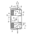
- FIG. 1 is a cross-sectional view in the axis X direction of the housing of the gas generator of the present invention.
- FIG. 2 is a sectional view in the axis X direction of the housing of the gas generator according to another embodiment of the present invention.
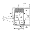
- FIG. 3 is a sectional view in the direction of the axis X of the housing of the gas generator which is still another embodiment of the present invention.
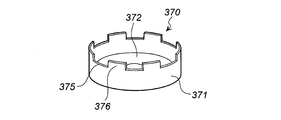
- 4 is a perspective view of an inner cylindrical wall that can be used in the gas generator of FIG. 2 or FIG.
- FIG. 5 is a perspective view of an inner cylindrical wall portion which is another embodiment that can be used in the gas generator of FIG. 2 or FIG. 3.
- the gas generator disclosed in Japanese Patent Application Laid-Open No. 2010-163025 has improved ignition and combustibility of the gas generating agent in the combustion chamber, but has such ignitability that the gas generating agent in the combustion chamber burns at once. Since it aims at improving, the structure which discharges
- the present invention provides a gas generator suitable for a person restraining device such as an air bag device, which uses one ignition means and can cause a time difference in the ignition start time of the gas generating agent filled in the combustion chamber.
- a person restraining device such as an air bag device
- the issue is to provide.
- the inner cylindrical wall portion is arranged in the combustion chamber filled with the gas generating agent, so that the gas generating agent ignites and burns relatively quickly in the combustion chamber (hereinafter referred to as “the gas generating agent”). And a space where the gas generating agent ignites and burns relatively slowly (hereinafter referred to as “late ignition space”).
- the initial ignition space is formed on the inner side in the radial direction of the inner cylindrical wall portion.
- the late ignition space is formed on the radially outer side of the inner cylindrical wall portion.
- the first communicating portion that communicates the ignition means chamber and the combustion chamber and the inner cylindrical wall portion face each other in the housing radial direction.
- the height from the bottom plate of the upper end of the opening that forms the first communicating portion is preferably less than half the height (h1) from the bottom plate to the upper end of the inner cylindrical wall portion.
- the combustion products when the ignition means in the ignition means chamber is operated and combustion products (flame, combustion gas, etc.) are discharged from the first communicating portion into the combustion chamber, the combustion products are in the radial direction of the housing.
- the gas generating agent filled in the initial ignition space is ignited and combusted to generate combustion gas.
- released from the 1st communication part collides with an inner cylindrical wall part, after burning the gas generating agent in an initial stage ignition space.
- the unburned gas generating agent existing in the direction (top plate side) is ignited.
- the gas generated at this time flows through a vent formed in the annular partition wall and flows into a space formed on the combustion chamber.
- the gas generating agent present in the late ignition space is present at a position opposite to the flow of the combustion gas in the direction of the axis X, and ignition is delayed.
- a large number of the air holes can be formed uniformly in the annular partition wall, thereby preventing the passage of combustion gas, or a part of the gas generated in the initial ignition space is reflected to ignite the gas in the late ignition space. To control.
- the initial ignition space and the late ignition space on the opposite side of the axis X direction with respect to the gas outlet in the combustion chamber, it is possible to cause a time difference in the ignition start time of the gas generating agent filled in the combustion chamber. Therefore, the combustion gas can be released so as to draw the above S-shaped curve.
- the inner side of the inner cylindrical wall portion is directly communicated with the first communication portion as the initial ignition space and the late ignition space is formed on the outer side in the radial direction, the above-described effects are obtained. It becomes easy.
- the inner cylindrical wall portion satisfies at least the requirement (a) among the requirements selected from the following requirements (a) to (c):
- the requirement (a) is that the ratio (h1 / h2) of the height (h1) from the bottom plate to the upper end of the inner cylindrical wall portion and the height (h2) from the bottom plate to the annular partition wall portion is 0. It is a gas generator for personnel restraint devices in the range of 3 to 0.7.
- A The height range of the inner cylindrical wall portion from the bottom plate in the housing axial direction is adjusted.
- B) The distance between the inner cylindrical wall portion and the ignition means chamber housing is adjusted.
- C) The inclination angle of the inner cylindrical wall portion with respect to the bottom plate is adjusted.
- the inner cylindrical wall is arranged in the combustion chamber, an initial ignition space and a late ignition space are formed, and a time difference can be caused in the ignition combustion time of the gas generating agent filled in the combustion chamber.
- the combustion gas can be released so as to draw the above S curve.
- the requirement (a) to a predetermined range
- the time difference between the ignition start time of the gas generating agent filled in the initial ignition space and the ignition start time of the gas generating agent charged in the late ignition space Can be adjusted to a more desirable range.
- the requirements (b) and (c) can be adjusted as necessary to adjust the volumes of the initial ignition space and the late ignition space (filling amount of the gas generating agent).
- the requirement (b) is the ratio (L1 / L2) of the distance (L1) from the ignition means chamber housing to the inner cylindrical wall and the distance (L2) from the ignition means chamber housing to the outer cylindrical wall. ) Is preferably in the range of 0.1 to 0.9, more preferably in the range of 0.3 to 0.7. L1 is the longest distance from the outer peripheral surface of the ignition means chamber housing to the outer peripheral face of the inner cylindrical wall portion, and L2 is the longest interval from the outer peripheral surface of the ignition means chamber housing to the outer peripheral surface of the outer cylindrical wall portion. It is determined. In the present invention, the requirement (c) is preferably such that the angle between the bottom plate and the inner cylindrical wall portion on the side of the ignition means chamber housing is in the range of 70 ° to 140 °.
- the inner cylindrical wall portion has a cylindrical wall surface portion and an outer annular flat portion that extends from the outer peripheral edge of the lower end thereof toward the outer side of the housing radius
- the outer cylindrical wall portion has a cylindrical wall surface portion and an inner annular flat surface portion that extends from the inner peripheral edge of the lower end in the housing radius inner direction
- the inner cylindrical wall portion and the outer cylindrical wall portion are integrally formed in the outer annular plane portion and the inner annular plane portion, It is a gas generator for personnel restraint devices in which the outer peripheral surface of the cylindrical wall surface portion of the outer cylindrical wall portion is fitted in a state of being in contact with the peripheral wall portion where the gas discharge port of the housing is not formed.
- the inner cylindrical wall portion has a cylindrical wall surface portion and an inner annular flat surface portion extended in the housing radius inner direction from the inner peripheral edge at the lower end thereof, A gas generator for a person restraining device, wherein an inner peripheral edge of an inner annular flat portion of the inner cylindrical wall portion is fitted in contact with the ignition means or the ignition means chamber housing.
- the inner cylindrical wall portion can be attached so as to abut on the ignition means (a metal collar for fixing the igniter) or the ignition means chamber housing, it is easy to position. Moreover, adjustment of above-mentioned requirements (a) and (b) becomes easy by adjusting the height of the cylindrical wall surface part of an inner cylindrical wall part, and the length of an inner side annular plane part.
- the inner cylindrical wall portion has a cylindrical inclined wall surface portion that is inclined outward in the housing radial direction, and an inner annular flat surface portion that extends inward from the lower end inner peripheral edge in the housing radius inner direction,
- a gas generator for a person restraining device wherein an inner peripheral edge of an inner annular flat portion of the inner cylindrical wall portion is fitted in contact with the ignition means or the ignition means chamber housing.
- the inner cylindrical wall portion can be attached so as to abut on the ignition means (a metal collar for fixing the igniter) or the ignition means chamber housing, it is easy to position. Further, the above requirements (a) to (c) can be easily adjusted by adjusting the height and angle of the cylindrical wall surface portion of the inner cylindrical wall portion and the length of the inner annular flat surface portion.
- the inner cylindrical wall portion has a cylindrical wall surface portion and an outer annular flat surface portion extended from the inner peripheral edge of the lower end in the housing radius outer direction,
- the peripheral edge portion on the upper end side of the cylindrical wall surface portion has irregularities in the housing axial direction, and the irregularities are formed in a plurality of locations in the circumferential direction, and h1 in the requirement (a) is from the bottom plate to the cylindrical shape.
- the outer cylindrical wall portion has a cylindrical wall surface portion and an inner annular flat surface portion that extends from the inner peripheral edge in the housing radius inner direction,
- the inner cylindrical wall portion and the outer cylindrical wall portion are integrally formed in the outer annular plane portion and the inner annular plane portion, It is a gas generator for personnel restraint devices in which the outer peripheral surface of the cylindrical wall surface portion of the outer cylindrical wall portion is fitted in a state of being in contact with the peripheral wall portion where the gas discharge port of the housing is not formed.
- the inner cylindrical wall portion and the outer cylindrical wall portion are integrated, two parts can be attached at a time, so that the attaching operation is facilitated. Moreover, by adjusting the height and angle of the cylindrical wall surface part of the inner cylindrical wall part, and the lengths of the outer annular plane part and the inner annular plane part, the above requirements (a), (b), and (c) Adjustment becomes easy. Furthermore, the above-described requirement (a) can be finely adjusted by using a cylindrical wall surface portion with irregularities formed as the inner cylindrical wall portion.
- the inner cylindrical wall portion is composed of a cylindrical wall surface portion and an inner annular flat surface portion extending in the housing radius inner direction from the inner peripheral edge at the lower end thereof,
- the peripheral wall portion on the upper end side of the cylindrical wall surface portion has irregularities in the housing axial direction, and the irregularities are formed at a plurality of locations in the circumferential direction.
- H1 in the requirement (a) is a height from the bottom plate to the concave portion of the cylindrical wall surface portion;
- a gas generator for a person restraining device wherein an inner peripheral edge of an inner annular flat portion of the inner cylindrical wall portion is fitted in contact with the ignition means or the ignition means chamber housing.
- the inner cylindrical wall portion can be attached so as to abut on the ignition means (a metal collar for fixing the igniter) or the ignition means chamber housing, it is easy to position. Moreover, adjustment of above requirements (a), (b), (c) becomes easy by adjusting the height and angle of the cylindrical wall surface part of the inner cylindrical wall part, and the length of the inner annular flat surface part. . Furthermore, the above-described requirement (a) can be finely adjusted by using a cylindrical wall surface portion with irregularities formed as the inner cylindrical wall portion.
- the inner cylindrical wall portion is a cylindrical wall surface portion, and a plurality of through holes are formed in the circumferential direction.
- h1 is a gas generator for a personnel restraint device, which is a height from the bottom plate to a peripheral edge of a lower end of the through hole.
- Adjustment of the requirements (a), (b), and (c) described above is facilitated by adjusting the height and angle of the cylindrical wall surface portion of the inner cylindrical wall portion and the length of the inner annular flat surface portion. Furthermore, the above-mentioned requirements are obtained by using a cylindrical wall surface part with a through hole formed as the inner cylindrical wall part, and adjusting the opening diameter, number, and shape of the through hole, and the height from the bottom plate of the housing. (A) can be finely adjusted.
- the gas generator for a personnel restraint device is configured such that an annular filter is disposed in a space between the annular partition wall having the vent hole and the top plate.
- an annular filter is disposed in a space between the annular partition wall having the vent hole and the top plate.
- a known filter having a function of filtering and cooling the combustion gas can be used.
- the gas generator of the present invention even when the gas generating agent is ignited and combusted by one igniter, a time difference can be generated in the ignition start time of the gas generating agent filled in the combustion chamber. Therefore, it is possible to inflate the air bag by releasing the combustion gas so as to draw the above S curve.
- a metal housing 11 is formed by welding a diffuser shell 12 and a closure shell 13 at a contact portion.
- the diffuser shell 12 has a cup shape including a top plate 12 a and an upper peripheral wall portion 12 b having a plurality of gas discharge ports 14.
- the gas discharge port 14 is closed with aluminum tape from the inside for moisture prevention.
- the closure shell 13 has a cup shape composed of a bottom plate 13a and a lower peripheral wall portion 13b.
- a peripheral wall portion of the housing 11 is formed by the upper peripheral wall portion 12b and the lower peripheral wall portion 13b.
- the housing 11 has a contact portion welded and fixed (weld fixing portion 15) in a state where the closure shell 13 is fitted in the diffuser shell 12, and is attached to the inner peripheral surface of the weld fixing portion 15.
- welding fixing portion 15 has an annular step 15a as shown in FIG.
- An igniter 20 held by an igniter collar 21 and a resin 22 is disposed at the center of the bottom plate 13 a of the closure shell 13.
- the igniter collar 21 is integrated with the bottom plate 13a, but may be integrated with another member by welding.
- a cylindrical ignition means chamber housing 30 is disposed at the center of the housing 11 so as to cover the igniter 20 and the igniter collar 21.
- Inside the ignition means chamber housing 30 is an ignition means chamber 34, in which one igniter 20, which is an ignition means, a transfer agent or a gas generating agent (not shown) is accommodated.
- the cylindrical ignition means chamber housing 30 has a closed surface 31 on the top plate 12a side.
- the closing surface 31 is one in which the opening side on the top plate 12a side is closed with another member, or the opening side on the top plate 12a side is closed by contacting the top plate 12a.
- a cup-shaped housing can also be used.
- the inner peripheral surface 32a of the peripheral wall 32 of the cylindrical ignition means chamber housing 30 is in contact with the igniter collar 21 except for a part (non-contact portion).
- the inner peripheral surface 32a of the peripheral wall 32 and the igniter collar 21 are provided with a projection 36 protruding inward as shown in FIG. It may be fixed by pressing.
- a non-contact portion between the inner peripheral surface 32a of the peripheral wall 32 and the igniter collar 21 is formed with a combustion product passage 35 formed by a gap in the axis X direction.
- the ignition means chamber housing 30 has a first communication portion 33 formed in a part of the peripheral wall 32 on the bottom plate 13a side.
- the first communication portion 33 is opened and is not closed by a closing member such as a seal tape.
- the first communication portion 33 is formed by a concave portion (a portion obtained by cutting the peripheral edge) formed in the opening direction side of the peripheral wall 32 or a through hole in the thickness direction.
- the first communication portion 33 is in communication with the ignition means chamber 34 through a combustion product passage 35.
- the outer cylindrical wall portion 40 includes a cylindrical wall surface portion 41 and an inner annular flat surface portion 42 that extends inward from the inner peripheral edge of the lower end side (bottom plate 13a side) of the housing.
- the inner annular flat surface portion 42 is in contact with the bottom plate 13 a, and a part of the cylindrical wall surface portion 41 is in contact with the lower peripheral wall portion 13 b of the closure shell 13.
- a cylindrical gas discharge path 16 communicating with the gas discharge port 14 is formed between the cylindrical wall surface portion 41 and the upper peripheral wall portion 12b of the diffuser shell 12 due to the annular step 15a.
- the outer cylindrical wall portion 40 includes a second communication portion 43 including a notch portion or an opening portion in which the top wall 12a side of the cylindrical wall surface portion 41 is partially cut.
- An annular partition 50 is disposed between the ignition means chamber housing 30 and the outer cylindrical wall 40 so as to form a space between the top plate 12a.
- the annular partition wall portion 50 includes an annular flat plate portion 51 having a plurality of vent holes 53 and an annular wall portion 52 extending from the inner peripheral edge of the annular flat plate portion 51 in the axis X direction.
- the ignition means chamber housing 30 is press-fitted and attached.
- the vent hole 53 is formed uniformly over the entire annular flat plate portion 51, and has an opening area that does not hinder when the combustion gas from the gas generating agent passes.
- An annular filter 80 is disposed in an annular space formed between the top plate 12 a and the annular partition wall 50.
- the annular filter 80 is a known filter that can filter and cool the combustion gas generated from the gas generating agent.
- the space formed by the annular partition wall 50 (the space where the annular filter 80 is disposed) and the gas discharge path 16 are communicated with each other by the second communication portion 43.
- the space formed by the combustion chamber 60 and the annular partition wall 50 is communicated with the vent hole 53 of the annular partition wall 50.
- the inner cylindrical wall portion 70 is further arranged in the combustion chamber 60.
- the inner cylindrical wall portion 70 includes a cylindrical wall surface portion 71 and an outer annular flat surface portion 72 that extends from the outer peripheral edge of the lower end side (bottom plate 13a side) toward the housing radial direction, on the bottom plate 13a. It arrange
- the outer cylindrical wall portion 40 and the inner cylindrical wall portion 70 are integrally formed with the inner annular plane portion 42 and the outer annular plane portion 72, but may be separated.
- the cylindrical wall surface portion 71 is arranged with a space between the ignition means chamber housing 20 and the outer cylindrical wall portion 40 and with a space between the annular partition wall portion 50.
- the inner cylindrical wall portion 70 satisfies at least the requirement (a) among the requirements selected from the following requirements (a) to (c). ⁇ Requirement (a)>
- the height range in the housing axial direction from the bottom plate 13a of the inner cylindrical wall portion 70 is adjusted.
- the requirement (b) is the ratio (L1 / L2) of the distance (L1) from the ignition means chamber housing 30 to the inner cylindrical wall portion 70 and the distance (L2) from the ignition means chamber housing 30 to the outer cylindrical wall portion 40. Is preferably in the range of 0.3 to 0.7.
- L1 / L2 0.5.
- the requirement (c) is that the angle between the bottom plate 13a and the inner cylindrical wall portion 70 on the ignition means chamber housing 30 side is in the range of 70 ° to 140 °. In the gas generator 10 of FIG. 1, the said angle is 90 degrees.
- the inner cylindrical wall portion 70 (cylindrical wall surface portion 71) and the first communication portion 33 face each other in the housing radial direction.
- the height from the bottom plate 13a at the upper end of the opening that forms the first communication portion 33 is less than half the height (h1) from the bottom plate 13a to the inner cylindrical wall portion 70 (cylindrical wall surface portion 71). Preferably there is.
- the transfer charge or gas generating agent is ignited and burned, and combustion products (flame, combustion gas, etc.) are generated.
- combustion products flame, combustion gas, etc.
- the gas generating agent filled in the initial ignition space between the ignition means chamber housing 30 and the inner cylindrical wall portion 70 is ignited and burned. Is done.
- the initial ignition space is an annular space surrounded by the bottom plate 13a of the closure shell, the cylindrical wall surface portion 71 of the inner cylindrical wall portion, and the peripheral wall 32 of the cylindrical ignition means chamber housing.
- Combustion products linearly travel radially outward from the first communication part 33 into the combustion chamber 60 and collide with the inner cylindrical wall part 70 (cylindrical wall part 71) facing the first communication part 33.
- the flow is changed in the axial direction (the direction of the top 12a, that is, the direction of the space in which the filter 80 is disposed).
- the gas generating agent present in the initial ignition space burns, and the combustion gas generated therefrom flows in the direction of the top plate 12a. Therefore, the unburned gas existing in that direction
- the generating agent is also ignited.
- the gas generating agent filled in the late ignition space (the space surrounded by the bottom plate 13a, the cylindrical wall surface portion 71 of the inner cylindrical wall portion, and the cylindrical wall surface portion 41 of the outer cylindrical wall portion) is the combustion gas. It does not exist in the direction of flow, and is difficult to ignite.
- the gas generator 100 in FIG. 2 differs from the gas generator 10 in FIG. 1 in that the shape of the outer cylindrical wall portion, the shape of the inner cylindrical wall portion, and the mounting state are different. Are the same including requirements (a) to (c) and can operate in the same manner.
- the outer cylindrical wall portion 140 has a cylindrical wall surface portion 141 and an inner annular flat surface portion 142 extending from the inner peripheral edge on the lower end side (bottom plate 13a side) toward the housing radius inside.
- the outer cylindrical wall portion 140 has an inner annular flat surface portion 142 in contact with the bottom plate 13 a and a cylindrical wall surface portion 141 in contact with the lower peripheral wall portion 13 b of the closure shell 13.
- a cylindrical gas discharge path 16 communicated with the gas discharge port 14 is formed between the cylindrical wall surface portion 141 and the upper peripheral wall portion 12b of the diffuser shell 12 due to the annular step 15a.
- the outer cylindrical wall portion 140 has a second communication portion 43 formed of a cutout portion or an opening portion in which the top wall 12a side of the cylindrical wall surface portion 141 is partially cut.
- the inner cylindrical wall portion 170 is disposed in the combustion chamber 60.
- the inner cylindrical wall portion 170 includes a cylindrical wall surface portion 171 and an inner annular flat surface portion 172 extending from the outer peripheral edge thereof toward the housing radius inward direction.
- the inner cylindrical wall portion 170 is disposed in a state where the inner annular flat surface portion 172 is placed on the bottom plate 13 a and the inner peripheral edge is in contact with the peripheral wall 32 of the ignition means chamber housing 30.
- the cylindrical wall surface portion 171 is spaced from the ignition means chamber housing 20 and the outer cylindrical wall portion 140 so as to satisfy the requirements (a) to (c), and is connected to the annular partition wall portion 50. It is arranged with a gap in between.
- the inner peripheral edge of the inner annular flat surface portion 172 may be in contact with the igniter collar 21, and the opening of the ignition means chamber housing 30 may be in contact with the inner annular flat surface portion 172.
- Gas Generator in FIG. 3 The gas generator 200 in FIG. 3 is the same as the gas generator 100 in FIG. 2 except that the shape of the inner cylindrical wall is different, and can operate in the same manner. it can.
- the inner cylindrical wall portion 270 is disposed in the combustion chamber 60.
- the inner cylindrical wall portion 270 includes a cylindrical wall surface portion 271 and an inner annular flat surface portion 272 that extends from the outer peripheral edge of the lower end side (bottom plate 13a side) toward the housing radius.
- the cylindrical wall surface portion 271 is an inclined wall surface portion whose upper end side is inclined outward in the radial direction.
- the inner cylindrical wall portion 270 shown in FIG. 3 can be formed in the same shape as the inner cylindrical wall portion 70 shown in FIG. 1 and integrated with the outer cylindrical wall portion.
- the cylindrical wall surface portion 271 is an inclined wall surface portion whose upper end side is inclined inward in the radial direction.
- the inner cylindrical wall portion 270 is disposed in a state where the inner annular flat surface portion 272 is placed on the bottom plate 13 a and the inner peripheral edge is in contact with the peripheral wall 32 of the ignition means chamber housing 30. At this time, the cylindrical wall surface portion 271 is spaced from the ignition means chamber housing 30 and the outer cylindrical wall portion 140 so as to satisfy the following requirements (a) to (c) and It is arranged with a gap in between.
- the inner peripheral edge of the inner annular flat surface portion 272 may be in contact with the igniter collar 21, and the opening of the ignition means chamber housing 20 may be in contact with the inner annular flat surface portion 272.
- the inner cylindrical wall portion 370 includes a cylindrical wall surface portion 371 and an inner annular flat surface portion 372 extending from the inner peripheral edge thereof toward the housing radius inward direction.
- the cylindrical wall surface portion 371 has a concave portion 375 and a convex portion 376 in the housing axis X direction at the upper peripheral wall portion.
- the concave portions 375 and the convex portions 376 are alternately formed in the circumferential direction.
- h1 in the requirement (a) is the height from the bottom plate 13a to the concave portion 375 of the cylindrical wall surface portion.
- the inner cylindrical wall portion 370 shown in FIG. 4 can be formed in the same shape as the inner cylindrical wall portion 70 shown in FIG. 1 and integrated with the outer cylindrical wall portion.
- the inner cylindrical wall portion 370 shown in FIG. 4 is adjusted in the late ignition space after the ignition of the gas generating agent in the initial ignition space by adjusting the depth per one concave portion 375 and the length and number in the circumferential direction. The timing of ignition / combustion of the existing gas generant can be adjusted.
- the inner cylindrical wall portion 370 shown in FIG. 4 may have an inclined wall surface portion 271 as shown in FIG.
- Inner cylindrical wall of another embodiment that can be used in the gas generator of FIGS. 2 and 3 (FIG. 5) 2 and 3, an inner cylindrical wall portion 470 as shown in FIG. 5 can be used.
- the inner cylindrical wall portion 470 includes a cylindrical wall surface portion 471 and an inner annular flat surface portion 472 extending from the inner peripheral edge thereof toward the housing radius inner side.
- the cylindrical wall surface portion 471 has a plurality of through holes 473 in the thickness direction in the peripheral wall portion.
- the through holes 473 are formed at equal intervals in the circumferential direction at the same height position.
- h ⁇ b> 1 in the requirement (a) is the height from the bottom plate 13 a to the lower end periphery of the through hole 473.
- the inner cylindrical wall portion 470 shown in FIG. 5 can be formed in the same shape as the inner cylindrical wall portion 70 shown in FIG. 1 and integrated with the outer cylindrical wall portion.
- the inner cylindrical wall portion 470 shown in FIG. 5 is present in the late ignition space after ignition of the gas generating agent in the initial ignition space by adjusting the size, number, and height position of each through hole 473. The timing of ignition and combustion of the gas generating agent to be adjusted can be adjusted.
- the inner cylindrical wall portion 470 shown in FIG. 5 may have an inclined wall surface portion 271 as shown in FIG.
Landscapes
- Physics & Mathematics (AREA)
- Fluid Mechanics (AREA)
- Engineering & Computer Science (AREA)
- Mechanical Engineering (AREA)
- Air Bags (AREA)
- Feeding, Discharge, Calcimining, Fusing, And Gas-Generation Devices (AREA)
Abstract
Description
ガス発生剤を使用するガス発生器には、燃焼室における着火開始部分と燃焼ガスを燃焼室から排出する出口の位置を調整することで、燃焼室に充填されたガス発生剤の着火・燃焼性を向上させたものが知られている。
このため、通気部27近傍で着火したガス発生剤から高温の燃焼ガスが発生し、それが軸方向上側(空間60側)に流れるので、作動初期には未燃焼状態である多孔部材50寄りのガス発生剤も燃焼しやすく、燃焼室40内部全体のガス発生剤の着火性能が向上する。
本発明は、
天板、ガス排出口を有する周壁部および底板からなるハウジングと、
前記ハウジング内部に配置された、点火手段が収容された点火手段室を形成する、一端側開口部が閉塞された筒状の点火手段室ハウジングと、
前記ハウジング周壁部との間で、前記ガス排出口と連通されたガス排出経路を形成するように配置された外側筒状壁部と、
前記点火手段室ハウジングと前記外側筒状壁部の間において、天板との間に空間を形成するように配置された、通気孔を有する環状隔壁部を有しており、
前記天板、前記底板、前記点火手段室ハウジングおよび前記外側筒状壁部で囲まれた空間が燃焼室となり、前記燃焼室内にはガス発生剤が充填されているものであり、
さらに燃焼室内において、前記点火手段室ハウジングと前記外側筒状壁部との間に間隔をおき、かつ前記環状隔壁部との間に間隔をおいて底板上に配置された内側筒状壁部を有しており、
前記点火手段室と前記燃焼室が、前記点火手段室ハウジングの前記底板側の周壁部に設けられた開口部からなる第1連通部で連通されており、
前記燃焼室と前記環状隔壁部で形成された空間が、前記環状隔壁部の通気孔で連通されており、
前記環状隔壁部で形成された空間と前記ガス排出口と連通されたガス排出経路が、前記外側筒状壁部と前記天板との間に形成された開口部からなる第2連通部で連通されており、
前記第1連通部と前記内側筒状壁部がハウジング半径方向に正対しており、
前記点火手段室で発生した燃焼生成物が、前記第1連通部を通過した後に前記内側筒状壁部に衝突して前記第2連通部が設けられている天板方向に向かって流れを変え、前記環状隔壁部の通気孔を通過する、人員拘束装置用ガス発生器を提供する。
特開2010-163025号公報のガス発生器は、燃焼室内のガス発生剤の着火燃焼性が向上されているが、燃焼室内のガス発生剤を一気に燃焼させるような着火性を向上させることを目的としているので、上記のようなS字カーブを描くように燃焼ガスを放出させる構成は、特開2010-163025号公報の本来の目的から反することである。
さらに図2のガス発生器では、少量ガス発生剤部21からの燃焼ガスを、開口23を通して大量ガス発生剤部22に着火させることが記載されており、図1と同様に本来の効果を得ることが難しく、図3のガス発生器でも同様のことが考えられる。
よって、図1~図3のガス発生器では、上記のようなS字カーブを描くように燃焼ガスを放出させることが難しいことが考えられる。
初期着火空間は、内側筒状壁部の半径方向内側に形成されている。また後期着火空間は、内側筒状壁部の半径方向外側に形成されている。
また本発明のガス発生器では、点火手段室と燃焼室を連通する第1連通部と内側筒状壁部がハウジング半径方向に正対している。
本発明においては、第1連通部を形成する開口部上端の底板からの高さは、底板から内側筒状壁部上端までの高さ(h1)の半分以下の高さであることが好ましい。
そして、第1連通部から放出された燃焼生成物は、初期着火空間内のガス発生剤を燃焼させた後で内側筒状壁部に衝突する。
ハウジング内には、第2連通部とガス排出口と連通されたガス排出経路が天板側にあることから、この燃焼ガスは燃焼生成物とともに天板方向に流れ、初期着火空間よりも軸X方向上(天板側)に存在する未燃焼のガス発生剤を着火させる。
このときに発生したガスは、環状隔壁部に形成された通気孔を通り、燃焼室の上に形成された空間に流れる。ただし、後期着火空間に存在するガス発生剤は、その軸X方向への燃焼ガスの流れとは逆の位置に存在しており、着火が遅れる。この通気孔は環状隔壁部に均一に多数形成することができ、これによって燃焼ガスの通過が妨げられたり、初期着火空間で発生したガスの一部が反射して後期着火空間のガスを着火させたりすることを制御する。
このように燃焼室内にガスの出口に対して軸X方向反対側に初期着火空間と後期着火空間を設けることで、燃焼室内に充填されたガス発生剤の着火開始時間に時間差を生じさせることができるため、上記のS字カーブを描くように燃焼ガスを放出させることができる。
本発明では、特に内側筒状壁部に対して半径方向内側を初期着火空間として第1連通部に直接連通させ、半径方向外側に後期着火空間を形成していることから、上記作用効果が得ることが容易になる。
前記内側筒状壁部が、下記の要件(a)~(c)から選ばれる要件のうち、少なくとも要件(a)を満たしており、
前記要件(a)が、前記底板から前記内側筒状壁部の上端までの高さ(h1)と前記底板から前記環状隔壁部までの高さ(h2)の比率(h1/h2)が0.3~0.7の範囲となる、人員拘束装置用ガス発生器である。
(a)前記内側筒状壁部の前記底板からのハウジング軸方向の高さ範囲が調整されていること
(b)前記内側筒状壁部と前記点火手段室ハウジングとの間隔が調整されていること
(c)前記内側筒状壁部の前記底板に対する傾斜角度が調整されていること
このとき、要件(a)を所定範囲に調整することで、初期着火空間内に充填されたガス発生剤の着火開始時間と、後期着火空間内に充填されたガス発生剤の着火開始時間の時間差をより望ましい範囲に調整することができる。
また必要に応じて要件(b)、(c)を調整して、初期着火空間と後期着火空間の容積(ガス発生剤の充填量)を調整することができる。
なお、L1は、点火手段室ハウジングの外周面から内側筒状壁部の外周面までの最長間隔、L2は、点火手段室ハウジングの外周面から外側筒状壁部の外周面までの最長間隔で決定される。
さらに本発明においては、要件(c)は、底板と内側筒状壁部の点火手段室ハウジング側の角度が70°~140°の範囲となるものが好ましい。
前記内側筒状壁部が、筒状壁面部とその下端外周縁からハウジング半径外側方向に延ばされた外側環状平面部を有しているものであり、
前記外側筒状壁部が、筒状壁面部とその下端内周縁からハウジング半径内側方向に延ばされた内側環状平面部を有しているものであり、
前記内側筒状壁部と前記外側筒状壁部が、前記外側環状平面部と前記内側環状平面部において一体に形成されているものであり、
前記外側筒状壁部の筒状壁面部の外周面が、ハウジングのガス排出口が形成されていない周壁部に当接された状態で嵌め込まれている、人員拘束装置用ガス発生器である。
また、内側筒状壁部の筒状壁面部の高さや角度、外側環状平面部と内側環状平面部の長さを調整することで、上記した要件(a)、(b)、(c)の調整が容易になる。
前記内側筒状壁部が、筒状壁面部と、その下端内周縁からハウジング半径内側方向に延ばされた内側環状平面部を有しているものであり、
前記内側筒状壁部の内側環状平面部の内周縁が、前記点火手段または前記点火手段室ハウジングに当接された状態で嵌め込まれている、人員拘束装置用ガス発生器である。
また、内側筒状壁部の筒状壁面部の高さ、内側環状平面部の長さを調整することで、上記した要件(a)、(b)の調整が容易になる。
前記内側筒状壁部が、ハウジング半径方向外側に傾いた筒状の傾斜壁面部と、その下端内周縁からハウジング半径内側方向に延ばされた内側環状平面部を有しているものであり、
前記内側筒状壁部の内側環状平面部の内周縁が、前記点火手段または前記点火手段室ハウジングに当接された状態で嵌め込まれている、人員拘束装置用ガス発生器である。
また、内側筒状壁部の筒状壁面部の高さや角度、内側環状平面部の長さを調整することで、上記した要件(a)~(c)の調整が容易になる。
前記内側筒状壁部が、筒状壁面部と、その下端内周縁からハウジング半径外側方向に延ばされた外側環状平面部を有しているものであり、
前記筒状壁面部の上端側の周縁部がハウジング軸方向への凹凸を有し、前記凹凸が周方向に複数箇所形成されており、前記要件(a)におけるh1が、前記底板から前記筒状壁面部の凹部までの高さであるものであり、
前記外側筒状壁部が、筒状壁面部とその内周縁からハウジング半径内側方向に延ばされた内側環状平面部を有しているものであり、
前記内側筒状壁部と前記外側筒状壁部が、前記外側環状平面部と前記内側環状平面部において一体に形成されているものであり、
前記外側筒状壁部の筒状壁面部の外周面が、ハウジングのガス排出口が形成されていない周壁部に当接された状態で嵌め込まれている、人員拘束装置用ガス発生器である。
また、内側筒状壁部の筒状壁面部の高さや角度、外側環状平面部と内側環状平面部の長さを調整することで、上記した要件(a)、(b)、(c)の調整が容易になる。
さらに内側筒状壁部として筒状壁面部に凹凸を形成したものを使用することで、上記した要件(a)を微調整できるようになる。
前記内側筒状壁部が、筒状壁面部と、その下端内周縁からハウジング半径内側方向に延ばされた内側環状平面部からなるものであり、
前記筒状壁面部の上端側の周壁部がハウジング軸方向への凹凸を有し、前記凹凸が周方向に複数箇所形成されているものであり、
前記要件(a)におけるh1が、前記底板から前記筒状壁面部の凹部までの高さであり、
前記内側筒状壁部の内側環状平面部の内周縁が、前記点火手段または前記点火手段室ハウジングに当接された状態で嵌め込まれている、人員拘束装置用ガス発生器である。
また、内側筒状壁部の筒状壁面部の高さや角度、内側環状平面部の長さを調整することで、上記した要件(a)、(b)、(c)の調整が容易になる。
さらに内側筒状壁部として筒状壁面部に凹凸を形成したものを使用することで、上記した要件(a)を微調整できるようになる。
前記内側筒状壁部が、筒状壁面部において、複数の貫通孔が周方向に形成されているものであり、
前記要件(a)におけるh1が、前記底板から前記貫通孔の下端周縁までの高さである、人員拘束装置用ガス発生器である。
さらに内側筒状壁部として筒状壁面部に貫通孔を形成したものを使用し、その貫通孔の開口径や数、および形状、ならびにハウジングの底板からの高さを調整することで上記した要件(a)を微調整できるようになる。
フィルタは、燃焼ガスを濾過及び冷却する機能を有している公知のフィルタを使用することができる。
(1)図1のガス発生器
図1のガス発生器10において、金属製のハウジング11は、ディフューザシェル12とクロージャシェル13が接触部において溶接固定されたものである。
ディフューザシェル12は、天板12a、複数のガス排出口14を有する上部周壁部12bからなるカップ状のものである。ガス排出口14は、防湿のため、内側からアルミニウムテープで閉塞されている。
クロージャシェル13は、底板13aと下部周壁部13bからなるカップ状のものである。
上部周壁部12bと下部周壁部13bによりハウジング11の周壁部が形成されている。
図1に示すとおり、ハウジング11は、ディフューザシェル12内にクロージャシェル13が嵌め込まれた状態にて、接触部が溶接固定されており(溶接固定部15)、溶接固定部15の内周面には図1に示すような環状段差15aが生じている。
ハウジング11の中央部には、筒状の点火手段室ハウジング30が点火器20および点火器カラー21に対して被せられた状態で配置されている。
点火手段室ハウジング30の内側は点火手段室34となっており、内部には点火手段となる、一つの点火器20、図示していない伝火薬又はガス発生剤が収容されている。
筒状の点火手段室ハウジング30は、天板12a側が閉塞面31となっている。
閉塞面31は、天板12a側の開口部側が別部材で閉塞されたもの、または天板12a側の開口部側が天板12aに当接されて閉塞されたものである。その他、カップ状ハウジングを使用することもできる。
周壁32の内周面32aと点火器カラー21は、点火器カラー21に対する点火手段室ハウジング30の固定強度を高めるため、図1に示すように内側に突き出された突出部36により点火器カラー21を押すようにして固定されていてもよい。
周壁32の内周面32aと点火器カラー21の非接触部分には、軸X方向への隙間からなる燃焼生成物の通路35が形成されている。
第1連通部33は、周壁32の開口部側に形成された軸X方向の凹部(周縁を切り取った部分)または厚さ方向への貫通孔からなるものである。
第1連通部33は、燃焼生成物の通路35を介して、点火手段室34と連通されている。
外側筒状壁部40は、内側環状平面部42が底板13aに当接され、かつ筒状壁面部41の一部がクロージャシェル13の下部周壁部13bに当接されている。
そして、環状段差15aがあることにより筒状壁面部41とディフューザシェル12の上部周壁部12bの間には、ガス排出口14と連通された筒状のガス排出経路16が形成されている。
外側筒状壁部40は、筒状壁面部41の天板12a側が部分的に切除された切り欠き部または開口部からなる第2連通部43を有している。
環状隔壁部50は、複数の通気孔53を有する環状平板部51と、環状平板部51の内周縁から軸X方向に延ばされた環状壁部52を有しており、環状壁部52において点火手段室ハウジング30に圧入されて取り付けられている。通気孔53は、環状平板部51全体にわたって均一に形成されており、ガス発生剤からの燃焼ガスが通過するときに妨げにならない開口面積を有している。
天板12aと環状隔壁部50の間に形成された環状空間には、環状のフィルタ80が配置されている。環状フィルタ80は、ガス発生剤から発生した燃焼ガスを濾過および冷却することができる公知のフィルタである。
環状隔壁部50で形成された空間(環状フィルタ80が配置された空間)とガス排出経路16は、第2連通部43で連通されている。
燃焼室60と環状隔壁部50で形成された空間は、環状隔壁部50の通気孔53で連通されている。
内側筒状壁部70は、筒状壁面部71とその下端側(底板13a側)の外周縁からハウジング半径外側方向に延ばされた外側環状平面部72を有しており、底板13a上に外側環状平面部72が置かれた状態で配置されている。
図1では、外側筒状壁部40と内側筒状壁部70は、内側環状平面部42と外側環状平面部72が一体に形成されているが、分離されたものでもよい。
筒状壁面部71は、点火手段室ハウジング20と外側筒状壁部40との間に間隔をおき、かつ環状隔壁部50との間に間隔をおいて配置されている。
<要件(a)>
内側筒状壁部70の底板13aからのハウジング軸方向の高さ範囲が調整されていること。
要件(a)は、底板13aから内側筒状壁部70の上端までの高さ(h1)と底板13aから環状隔壁部50までの高さ(h2)の比率(h1/h2)が0.3~0.7の範囲となるものである。
図1のガス発生器10では、h1/h2=0.4である。
<要件(b)>
(b)内側筒状壁部70と点火手段室ハウジング30との間隔が調整されていること。
要件(b)は、点火手段室ハウジング30から内側筒状壁部70までの間隔(L1)と点火手段室ハウジング30から外側筒状壁部40までの間隔(L2)の比率(L1/L2)が好ましくは0.3~0.7の範囲となるものである。
図1のガス発生器10では、L1/L2=0.5である。
<要件(c)>
内側筒状壁部70の底板13aに対する傾斜角度が調整されていること。
要件(c)は、底板13aと内側筒状壁部70の点火手段室ハウジング30側の角度が70°~140°の範囲となるものである。
図1のガス発生器10では、前記角度は90°である。
第1連通部33を形成する開口部上端の底板13aからの高さは、底板13aから内側筒状壁部70(筒状壁面部71)までの高さ(h1)の半分以下の高さであることが好ましい。
発生した燃焼生成物が第1連通部33から燃焼室60内に放出されたとき、点火手段室ハウジング30と内側筒状壁部70の間の初期着火空間に充填されたガス発生剤が着火燃焼される。
ここで初期着火空間は、クロージャシェルの底板13a、内側筒状壁部の筒状壁面部71、筒状の点火手段室ハウジングの周壁32で囲まれた環状空間である。
そのとき、初期着火空間(筒状壁面部71の内側空間)に存在するガス発生剤が燃焼し、そこから発生した燃焼ガスが天板12a方向に流れるため、その方向に存在する未燃焼のガス発生剤も着火させる。
しかし、後期着火空間(底板13a、内側筒状壁部の筒状壁面部71、外側筒状壁部の筒状壁面部41で囲まれた空間)に充填されたガス発生剤は、その燃焼ガスの流れる方向に存在せず、着火しにくい状態である。
つまり、初期着火空間のガス発生剤が着火燃焼して燃焼ガスが発生し、ガス排出口14から排出された後で、後期着火空間のガス発生剤が着火燃焼して燃焼ガスが発生し、ガス排出口14から排出されるため、S字カーブを描くように燃焼ガスを放出してエアバッグを膨張させることができる。
特に本発明のガス発生器では、筒状壁面部71により向きを変えた燃焼生成物が、第2連通部43と連通されているフィルタ80が配置された空間に至るまで直線的に流れて初期着火空間上にある燃焼室60内のガス発生剤を着火燃焼させるため、後期着火空間に存在するガス発生剤に与える影響が少ない。
よって、初期着火空間に存在するガス発生剤との着火タイミングを際立たせることができる。
図2のガス発生器100は、図1のガス発生器10とは、外側筒状壁部の形状と、内側筒状壁部の形状および取り付け状態が異なるほかは、要件(a)~(c)も含めて同じものであり、同様に動作することができる。
外側筒状壁部140は、内側環状平面部142が底板13aに当接され、かつ筒状壁面部141がクロージャシェル13の下部周壁部13bに当接されている。
そして、環状段差15aがあることにより筒状壁面部141とディフューザシェル12の上部周壁部12bの間には、ガス排出口14と連通された筒状のガス排出経路16が形成されている。
外側筒状壁部140は、筒状壁面部141の天板12a側が部分的に切除された切り欠き部または開口部からなる第2連通部43を有している。
内側筒状壁部170は、筒状壁面部171とその外周縁からハウジング半径内側方向に延ばされた内側環状平面部172を有している。
内側筒状壁部170は、内側環状平面部172が底板13aに置かれ、内周縁が点火手段室ハウジング30の周壁32に当接された状態で配置されている。
このとき、筒状壁面部171は、要件(a)~(c)を満たすように、点火手段室ハウジング20と外側筒状壁部140との間に間隔をおき、かつ環状隔壁部50との間に間隔をおいて配置されている。
なお、内側環状平面部172の内周縁が点火器カラー21に当接され、内側環状平面部172の上に点火手段室ハウジング30の開口部が当接されていてもよい。
図3のガス発生器200は、図2のガス発生器100とは、内側筒状壁部の形状が異なるほかは同じものであり、同様に動作することができる。
内側筒状壁部270は、筒状壁面部271と、その下端側(底板13a側)の外周縁からハウジング半径内側方向に延ばされた内側環状平面部272を有している。
筒状壁面部271は、その上端側が半径方向外側に傾いた傾斜壁面部となっている。
なお、図3で示す内側筒状壁部270は、図1に示す内側筒状壁部70と同様の形状にして外側筒状壁部と一体にしたものにすることもできるが、その場合には、筒状壁面部271は、その上端側が半径方向内側に傾いた傾斜壁面部となっている。
内側筒状壁部270は、内側環状平面部272が底板13aに置かれ、内周縁が点火手段室ハウジング30の周壁32に当接された状態で配置されている。
このとき、筒状壁面部271は、下記要件(a)~(c)を満たすように点火手段室ハウジング30と外側筒状壁部140との間に間隔をおき、かつ環状隔壁部50との間に間隔をおいて配置されている。
なお、内側環状平面部272の内周縁が点火器カラー21に当接され、内側環状平面部272の上に点火手段室ハウジング20の開口部が当接されていてもよい。
要件(a):h1/h2=0.4
要件(b):L1/L2=0.5(L1は、筒状壁面部271と内側環状平面部272との外側角部までの長さである。)
要件(c):底板13aと内側筒状壁部270(筒状壁面部271)の点火手段室ハウジング30側の角度が115°
図2および図3のガス発生器では、図4に示すような内側筒状壁部370を使用することができる。
内側筒状壁部370は、筒状壁面部371とその内周縁からハウジング半径内側方向に延ばされた内側環状平面部372を有している。
筒状壁面部371は、その上端側の周壁部がハウジング軸X方向への凹部375と凸部376を有している。
凹部375と凸部376は、周方向に交互に形成されている。
図4に示す内側筒状壁部370では、要件(a)におけるh1は底板13aから筒状壁面部の凹部375までの高さである。
なお、図4で示す内側筒状壁部370は、図1に示す内側筒状壁部70と同様の形状にして、外側筒状壁部と一体にしたものにすることもできる。
図4に示す内側筒状壁部370は、凹部375の一つあたりの深さや円周方向の長さおよび数を調整することによって、初期着火空間のガス発生剤の着火後における後期着火空間に存在するガス発生剤の着火・燃焼のタイミングを調整することができる。
また図4に示す内側筒状壁部370は、図3に示すような傾斜壁面部271を有するものにすることもできる。
図2および図3のガス発生器では、図5に示すような内側筒状壁部470を使用することができる。
内側筒状壁部470は、筒状壁面部471とその内周縁からハウジング半径内側方向に延ばされた内側環状平面部472を有している。
筒状壁面部471は、周壁部において厚さ方向への複数の貫通孔473を有している。
貫通孔473は、同じ高さ位置において、周方向に等間隔で形成されている。
図5に示す内側筒状壁部470では、要件(a)におけるh1は底板13aから貫通孔473の下端周縁までの高さである。
なお、図5で示す内側筒状壁部470は、図1に示す内側筒状壁部70と同様の形状にして、外側筒状壁部と一体にしたものにすることもできる。
図5に示す内側筒状壁部470は、貫通孔473の一つあたりの大きさ、数、高さ位置を調整することによって、初期着火空間のガス発生剤の着火後における後期着火空間に存在するガス発生剤の着火・燃焼のタイミングを調整することができる。
また図5に示す内側筒状壁部470は、図3に示すような傾斜壁面部271を有するものにすることもできる。
Claims (11)
- 天板、ガス排出口を有する周壁部および底板からなるハウジングと、
前記ハウジング内部に配置された、点火手段が収容された点火手段室を形成する、一端側開口部が閉塞された筒状の点火手段室ハウジングと、
前記ハウジング周壁部との間で、前記ガス排出口と連通されたガス排出経路を形成するように配置された外側筒状壁部と、
前記点火手段室ハウジングと前記外側筒状壁部の間において、天板との間に空間を形成するように配置された、通気孔を有する環状隔壁部を有しており、
前記天板、前記底板、前記点火手段室ハウジングおよび前記外側筒状壁部で囲まれた空間が燃焼室となり、前記燃焼室内にはガス発生剤が充填されているものであり、
さらに燃焼室内において、前記点火手段室ハウジングと前記外側筒状壁部との間に間隔をおき、かつ前記環状隔壁部との間に間隔をおいて底板上に配置された内側筒状壁部を有しており、
前記点火手段室と前記燃焼室が、前記点火手段室ハウジングの前記底板側の周壁部に設けられた開口部からなる第1連通部で連通されており、
前記燃焼室と前記環状隔壁部で形成された空間が、前記環状隔壁部の通気孔で連通されており、
前記環状隔壁部で形成された空間と前記ガス排出口と連通されたガス排出経路が、前記外側筒状壁部と前記天板との間に形成された開口部からなる第2連通部で連通されており、
前記第1連通部と前記内側筒状壁部がハウジング半径方向に正対しており、
前記点火手段室で発生した燃焼生成物が、前記第1連通部を通過した後に前記内側筒状壁部に衝突して前記第2連通部が設けられている天板方向に向かって流れを変え、前記環状隔壁部の通気孔を通過する人員拘束装置用ガス発生器。 - 前記内側筒状壁部が、下記の要件(a)~(c)から選ばれる要件のうち、少なくとも要件(a)を満たしており、
前記要件(a)が、前記底板から前記内側筒状壁部の上端までの高さ(h1)と前記底板から前記環状隔壁部までの高さ(h2)の比率(h1/h2)が0.3~0.7の範囲となるものである、請求項1記載の人員拘束装置用ガス発生器。
(a)前記内側筒状壁部の前記底板からのハウジング軸方向の高さ範囲が調整されていること
(b)前記内側筒状壁部と前記点火手段室ハウジングとの間隔が調整されていること
(c)前記内側筒状壁部の前記底板に対する傾斜角度が調整されていること - 前記要件(b)が、前記点火手段室ハウジングから前記内側筒状壁部までの間隔(L1)と前記点火手段室ハウジングから前記外側筒状壁部までの間隔(L2)の比率(L1/L2)が0.1~0.9の範囲となるものであり、
前記要件(c)が、前記底板と前記内側筒状壁部の前記点火手段室ハウジング側の角度が70°~140°の範囲となるものである、請求項2記載の人員拘束装置用ガス発生器。 - さらに前記第1連通部を形成する開口部上端の前記底板からの高さが、前記底板から前記内側筒状壁部上端までの高さ(h1)の半分以下の高さである、請求項1~3のいずれか1項記載の人員拘束装置用ガス発生器。
- 前記内側筒状壁部が、筒状壁面部とその下端外周縁からハウジング半径外側方向に延ばされた外側環状平面部を有しているものであり、
前記外側筒状壁部が、筒状壁面部とその下端内周縁からハウジング半径内側方向に延ばされた内側環状平面部を有しているものであり、
前記内側筒状壁部と前記外側筒状壁部が、前記外側環状平面部と前記内側環状平面部において一体に形成されているものであり、
前記外側筒状壁部の筒状壁面部の外周面が、ハウジングのガス排出口が形成されていない周壁部に当接された状態で嵌め込まれている、請求項1~4のいずれか1項記載の人員拘束装置用ガス発生器。 - 前記内側筒状壁部が、筒状壁面部と、その下端内周縁からハウジング半径内側方向に延ばされた内側環状平面部を有しているものであり、
前記内側筒状壁部の内側環状平面部の内周縁が、前記点火手段または前記点火手段室ハウジングに当接された状態で嵌め込まれている、請求項1~4のいずれか1項記載の人員拘束装置用ガス発生器。 - 前記内側筒状壁部が、ハウジング半径方向外側に傾いた筒状の傾斜壁面部と、その下端内周縁からハウジング半径内側方向に延ばされた内側環状平面部を有しているものであり、
前記内側筒状壁部の内側環状平面部の内周縁が、前記点火手段または前記点火手段室ハウジングに当接された状態で嵌め込まれている、請求項1~4のいずれか1項記載の人員拘束装置用ガス発生器。 - 前記内側筒状壁部が、筒状壁面部と、その下端内周縁からハウジング半径外側方向に延ばされた外側環状平面部を有しているものであり、
前記筒状壁面部の上端側の周縁部がハウジング軸方向への凹凸を有し、前記凹凸が周方向に複数箇所形成されており、前記要件(a)におけるh1が、前記底板から前記筒状壁面部の凹部までの高さであるものであり、
前記外側筒状壁部が、筒状壁面部とその内周縁からハウジング半径内側方向に延ばされた内側環状平面部を有しているものであり、
前記内側筒状壁部と前記外側筒状壁部が、前記外側環状平面部と前記内側環状平面部において一体に形成されているものであり、
前記外側筒状壁部の筒状壁面部の外周面が、ハウジングのガス排出口が形成されていない周壁部に当接された状態で嵌め込まれている、請求項2~4のいずれか1項記載の人員拘束装置用ガス発生器。 - 前記内側筒状壁部が、筒状壁面部と、その下端内周縁からハウジング半径内側方向に延ばされた内側環状平面部からなるものであり、
前記筒状壁面部の上端側の周壁部がハウジング軸方向への凹凸を有し、前記凹凸が周方向に複数箇所形成されているものであり、
前記要件(a)におけるh1が、前記底板から前記筒状壁面部の凹部までの高さであり、
前記内側筒状壁部の内側環状平面部の内周縁が、前記点火手段または前記点火手段室ハウジングに当接された状態で嵌め込まれている、請求項2~4のいずれか1項記載の人員拘束装置用ガス発生器。 - 前記内側筒状壁部が、筒状壁面部において、複数の貫通孔が周方向に形成されているものであり、
前記要件(a)におけるh1が、前記底板から前記貫通孔の下端周縁までの高さである、請求項2~4のいずれか1項記載の人員拘束装置用ガス発生器。 - 前記通気孔を有する環状隔壁部と前記天板との間の空間内に環状のフィルタが配置されている、請求項1~10のいずれか1項記載の人員拘束装置用ガス発生器。
Priority Applications (4)
| Application Number | Priority Date | Filing Date | Title |
|---|---|---|---|
| CN201480034293.3A CN105339215B (zh) | 2013-06-21 | 2014-06-03 | 人员约束装置用气体发生器 |
| EP14814498.3A EP3012159B1 (en) | 2013-06-21 | 2014-06-03 | Gas generator for occupant restraining device |
| KR1020157034720A KR102162699B1 (ko) | 2013-06-21 | 2014-06-03 | 인원 구속 장치용 가스 발생기 |
| US14/894,411 US9487182B2 (en) | 2013-06-21 | 2014-06-03 | Gas generator for restraining device |
Applications Claiming Priority (2)
| Application Number | Priority Date | Filing Date | Title |
|---|---|---|---|
| JP2013130727A JP6009997B2 (ja) | 2013-06-21 | 2013-06-21 | 人員拘束装置用ガス発生器 |
| JP2013-130727 | 2013-06-21 |
Publications (1)
| Publication Number | Publication Date |
|---|---|
| WO2014203723A1 true WO2014203723A1 (ja) | 2014-12-24 |
Family
ID=52104464
Family Applications (1)
| Application Number | Title | Priority Date | Filing Date |
|---|---|---|---|
| PCT/JP2014/064702 Ceased WO2014203723A1 (ja) | 2013-06-21 | 2014-06-03 | 人員拘束装置用ガス発生器 |
Country Status (6)
| Country | Link |
|---|---|
| US (1) | US9487182B2 (ja) |
| EP (1) | EP3012159B1 (ja) |
| JP (1) | JP6009997B2 (ja) |
| KR (1) | KR102162699B1 (ja) |
| CN (1) | CN105339215B (ja) |
| WO (1) | WO2014203723A1 (ja) |
Families Citing this family (13)
| Publication number | Priority date | Publication date | Assignee | Title |
|---|---|---|---|---|
| DE102008060305A1 (de) * | 2008-12-03 | 2010-06-10 | Trw Airbag Systems Gmbh | Gasgenerator |
| JP6009997B2 (ja) * | 2013-06-21 | 2016-10-19 | 株式会社ダイセル | 人員拘束装置用ガス発生器 |
| DE102013020526A1 (de) * | 2013-12-11 | 2015-06-11 | Trw Airbag Systems Gmbh | Polkörper für einen pyrotechnischen anzünder eines gasgenerators, anzünder, gasgenerator und gassackmodul mit einem derartigen polkörper |
| JP6276110B2 (ja) * | 2014-05-09 | 2018-02-07 | 株式会社ダイセル | ガス発生器とその組み立て方法 |
| JP6749788B2 (ja) * | 2016-05-18 | 2020-09-02 | 株式会社ダイセル | ガス発生器 |
| JP6701040B2 (ja) * | 2016-09-14 | 2020-05-27 | 日本化薬株式会社 | ガス発生器用フィルタおよびガス発生器 |
| JP6798935B2 (ja) | 2017-04-28 | 2020-12-09 | 日本化薬株式会社 | ガス発生器 |
| JP6797072B2 (ja) * | 2017-05-01 | 2020-12-09 | 株式会社ダイセル | ガス発生器 |
| JP6954520B2 (ja) * | 2017-12-05 | 2021-10-27 | 株式会社ダイセル | 点火器組立体、及びガス発生器 |
| KR102622079B1 (ko) * | 2018-05-29 | 2024-01-09 | 주식회사 다이셀 | 가스 발생기 |
| JP7368325B2 (ja) * | 2020-06-18 | 2023-10-24 | 株式会社ダイセル | ガス発生器 |
| JP7394715B2 (ja) * | 2020-06-30 | 2023-12-08 | 株式会社ダイセル | 部材固定構造及びガス発生器 |
| DE112023002800T5 (de) * | 2022-06-28 | 2025-06-12 | Daicel Corporation | Gasgenerator und Gasauslassverfahren für einen Gasgenerator |
Citations (10)
| Publication number | Priority date | Publication date | Assignee | Title |
|---|---|---|---|---|
| US5009855A (en) | 1988-10-17 | 1991-04-23 | Bayern-Chemie Gesellschaft Fuer Flugchemische Antriebe Mbh | Gas generator for inflating a safety bag |
| US5628528A (en) | 1995-07-06 | 1997-05-13 | Automotive Systems Laboratory, Inc. | Dual chamber nonazide gas generator |
| JP2000026189A (ja) | 1997-03-24 | 2000-01-25 | Daicel Chem Ind Ltd | エアバッグ用ガス発生剤組成物成型体 |
| JP2002370607A (ja) * | 2001-06-14 | 2002-12-24 | Nippon Kayaku Co Ltd | ガス発生器 |
| JP2003191816A (ja) | 2001-12-26 | 2003-07-09 | Daicel Chem Ind Ltd | エアバッグ用ガス発生器 |
| US20040046373A1 (en) * | 2002-09-09 | 2004-03-11 | Chung Shan Institute Of Science & Technology | Dual stage airbag inflator |
| JP2008183939A (ja) * | 2007-01-26 | 2008-08-14 | Nippon Kayaku Co Ltd | ガス発生器 |
| JP2010163025A (ja) | 2009-01-15 | 2010-07-29 | Daicel Chem Ind Ltd | 車両の人員拘束装置用ガス発生器 |
| JP2010163044A (ja) * | 2009-01-15 | 2010-07-29 | Daicel Chem Ind Ltd | 車両の人員拘束装置用ガス発生器 |
| JP2012061960A (ja) * | 2010-09-16 | 2012-03-29 | Toyota Motor Corp | インフレータ |
Family Cites Families (22)
| Publication number | Priority date | Publication date | Assignee | Title |
|---|---|---|---|---|
| US6562161B1 (en) | 1997-03-24 | 2003-05-13 | Daicel Chemical Industries, Ltd. | Gas generating compositions for air bag |
| US6227565B1 (en) * | 1999-03-04 | 2001-05-08 | Trw Inc. | Air bag inflator with pressure regulation |
| JP2002360607A (ja) | 2001-06-07 | 2002-12-17 | Ajs:Kk | 咬合器 |
| US6948737B2 (en) | 2001-12-26 | 2005-09-27 | Daicel Chemical Industries, Ltd. | Gas generator for air bag |
| US7052040B2 (en) * | 2002-12-09 | 2006-05-30 | Daicel Chemical Industries, Ltd | Gas generator for air bag |
| DE20219899U1 (de) * | 2002-12-23 | 2003-05-28 | TRW Airbag Systems GmbH, 84544 Aschau | Gasgenerator |
| EP1669259B1 (de) * | 2004-12-08 | 2011-06-15 | Delphi Technologies, Inc. | Gasgenerator |
| US7520530B2 (en) * | 2004-12-20 | 2009-04-21 | Daicel Chemical Industries, Ltd. | Gas generator for air bag |
| US7503581B2 (en) * | 2006-03-22 | 2009-03-17 | Daicel Chemical Industries, Ltd. | Gas generator for occupant restraining device for vehicle |
| DE102007033344A1 (de) * | 2007-07-16 | 2009-05-07 | Takata-Petri Ag | Gasgenerator für eine Fahrzeuginsassen-Schutzvorrichtung und Verfahren zum Entfernen von Feststoffen und flüssigen Abbrandresten in einem Gasstrom |
| JP5090100B2 (ja) * | 2007-08-09 | 2012-12-05 | 豊田合成株式会社 | インフレーター |
| FR2927291B1 (fr) * | 2008-02-07 | 2016-03-04 | Livbag | Generateur de gaz pour un dispositif de securite, dont la charge est initiee par un moyen generateur de chaleur. |
| JP5324931B2 (ja) * | 2009-01-15 | 2013-10-23 | 株式会社ダイセル | 車両の人員拘束装置用ガス発生器 |
| JP5016619B2 (ja) * | 2009-01-15 | 2012-09-05 | 株式会社ダイセル | 車両の人員拘束装置用ガス発生器 |
| JP5922956B2 (ja) * | 2012-03-12 | 2016-05-24 | 株式会社ダイセル | ガス発生器 |
| JP5763000B2 (ja) * | 2012-03-19 | 2015-08-12 | 株式会社ダイセル | ガス発生器 |
| JP5873373B2 (ja) * | 2012-04-02 | 2016-03-01 | 株式会社ダイセル | ガス発生器 |
| JP5945152B2 (ja) * | 2012-04-25 | 2016-07-05 | 株式会社ダイセル | ガス発生器 |
| JP5912853B2 (ja) * | 2012-05-23 | 2016-04-27 | 株式会社ダイセル | ガス発生器 |
| JP6422628B2 (ja) * | 2012-10-18 | 2018-11-14 | 株式会社ダイセル | ガス発生剤組成物と、それを使用したガス発生器 |
| JP5956308B2 (ja) * | 2012-11-02 | 2016-07-27 | 株式会社ダイセル | 人員拘束装置用のガス発生器 |
| JP6009997B2 (ja) * | 2013-06-21 | 2016-10-19 | 株式会社ダイセル | 人員拘束装置用ガス発生器 |
-
2013
- 2013-06-21 JP JP2013130727A patent/JP6009997B2/ja not_active Expired - Fee Related
-
2014
- 2014-06-03 KR KR1020157034720A patent/KR102162699B1/ko active Active
- 2014-06-03 US US14/894,411 patent/US9487182B2/en active Active
- 2014-06-03 CN CN201480034293.3A patent/CN105339215B/zh active Active
- 2014-06-03 WO PCT/JP2014/064702 patent/WO2014203723A1/ja not_active Ceased
- 2014-06-03 EP EP14814498.3A patent/EP3012159B1/en active Active
Patent Citations (10)
| Publication number | Priority date | Publication date | Assignee | Title |
|---|---|---|---|---|
| US5009855A (en) | 1988-10-17 | 1991-04-23 | Bayern-Chemie Gesellschaft Fuer Flugchemische Antriebe Mbh | Gas generator for inflating a safety bag |
| US5628528A (en) | 1995-07-06 | 1997-05-13 | Automotive Systems Laboratory, Inc. | Dual chamber nonazide gas generator |
| JP2000026189A (ja) | 1997-03-24 | 2000-01-25 | Daicel Chem Ind Ltd | エアバッグ用ガス発生剤組成物成型体 |
| JP2002370607A (ja) * | 2001-06-14 | 2002-12-24 | Nippon Kayaku Co Ltd | ガス発生器 |
| JP2003191816A (ja) | 2001-12-26 | 2003-07-09 | Daicel Chem Ind Ltd | エアバッグ用ガス発生器 |
| US20040046373A1 (en) * | 2002-09-09 | 2004-03-11 | Chung Shan Institute Of Science & Technology | Dual stage airbag inflator |
| JP2008183939A (ja) * | 2007-01-26 | 2008-08-14 | Nippon Kayaku Co Ltd | ガス発生器 |
| JP2010163025A (ja) | 2009-01-15 | 2010-07-29 | Daicel Chem Ind Ltd | 車両の人員拘束装置用ガス発生器 |
| JP2010163044A (ja) * | 2009-01-15 | 2010-07-29 | Daicel Chem Ind Ltd | 車両の人員拘束装置用ガス発生器 |
| JP2012061960A (ja) * | 2010-09-16 | 2012-03-29 | Toyota Motor Corp | インフレータ |
Non-Patent Citations (1)
| Title |
|---|
| See also references of EP3012159A4 |
Also Published As
| Publication number | Publication date |
|---|---|
| KR102162699B1 (ko) | 2020-10-07 |
| JP2015003650A (ja) | 2015-01-08 |
| JP6009997B2 (ja) | 2016-10-19 |
| EP3012159B1 (en) | 2018-01-31 |
| EP3012159A4 (en) | 2017-02-08 |
| US20160121841A1 (en) | 2016-05-05 |
| KR20160024859A (ko) | 2016-03-07 |
| CN105339215B (zh) | 2017-12-26 |
| CN105339215A (zh) | 2016-02-17 |
| EP3012159A1 (en) | 2016-04-27 |
| US9487182B2 (en) | 2016-11-08 |
Similar Documents
| Publication | Publication Date | Title |
|---|---|---|
| JP6009997B2 (ja) | 人員拘束装置用ガス発生器 | |
| US9353703B2 (en) | Gas generator | |
| JP6282555B2 (ja) | ガス発生器 | |
| US8870222B2 (en) | Gas generator | |
| US7527289B2 (en) | Gas generator for an air bag | |
| KR102309123B1 (ko) | 가스 발생기 | |
| US10974687B2 (en) | Gas generator | |
| CN109641567B (zh) | 气体发生器 | |
| JP2010163043A (ja) | 車両の人員拘束装置用ガス発生器 | |
| WO2017179421A1 (ja) | ガス発生器 | |
| JP5912853B2 (ja) | ガス発生器 | |
| JP2002337655A (ja) | エアバック用ガス発生器 | |
| WO2019035285A1 (ja) | ガス発生器 | |
| WO2019098089A1 (ja) | ガス発生器 | |
| JP2007196977A (ja) | エアバッグ装置用ガス発生器 | |
| JP2015202825A (ja) | ガス発生器 |
Legal Events
| Date | Code | Title | Description |
|---|---|---|---|
| WWE | Wipo information: entry into national phase |
Ref document number: 201480034293.3 Country of ref document: CN |
|
| 121 | Ep: the epo has been informed by wipo that ep was designated in this application |
Ref document number: 14814498 Country of ref document: EP Kind code of ref document: A1 |
|
| WWE | Wipo information: entry into national phase |
Ref document number: 14894411 Country of ref document: US |
|
| ENP | Entry into the national phase |
Ref document number: 20157034720 Country of ref document: KR Kind code of ref document: A |
|
| WWE | Wipo information: entry into national phase |
Ref document number: 2014814498 Country of ref document: EP |
|
| NENP | Non-entry into the national phase |
Ref country code: DE |