WO2014203899A1 - パーキング装置 - Google Patents
パーキング装置 Download PDFInfo
- Publication number
- WO2014203899A1 WO2014203899A1 PCT/JP2014/066043 JP2014066043W WO2014203899A1 WO 2014203899 A1 WO2014203899 A1 WO 2014203899A1 JP 2014066043 W JP2014066043 W JP 2014066043W WO 2014203899 A1 WO2014203899 A1 WO 2014203899A1
- Authority
- WO
- WIPO (PCT)
- Prior art keywords
- shaft
- shaft member
- lock
- parking
- piston rod
- Prior art date
- Legal status (The legal status is an assumption and is not a legal conclusion. Google has not performed a legal analysis and makes no representation as to the accuracy of the status listed.)
- Ceased
Links
Images


Classifications
-
- F—MECHANICAL ENGINEERING; LIGHTING; HEATING; WEAPONS; BLASTING
- F16—ENGINEERING ELEMENTS AND UNITS; GENERAL MEASURES FOR PRODUCING AND MAINTAINING EFFECTIVE FUNCTIONING OF MACHINES OR INSTALLATIONS; THERMAL INSULATION IN GENERAL
- F16D—COUPLINGS FOR TRANSMITTING ROTATION; CLUTCHES; BRAKES
- F16D63/00—Brakes not otherwise provided for; Brakes combining more than one of the types of groups F16D49/00 - F16D61/00
- F16D63/006—Positive locking brakes
-
- B—PERFORMING OPERATIONS; TRANSPORTING
- B60—VEHICLES IN GENERAL
- B60T—VEHICLE BRAKE CONTROL SYSTEMS OR PARTS THEREOF; BRAKE CONTROL SYSTEMS OR PARTS THEREOF, IN GENERAL; ARRANGEMENT OF BRAKING ELEMENTS ON VEHICLES IN GENERAL; PORTABLE DEVICES FOR PREVENTING UNWANTED MOVEMENT OF VEHICLES; VEHICLE MODIFICATIONS TO FACILITATE COOLING OF BRAKES
- B60T1/00—Arrangements of braking elements, i.e. of those parts where braking effect occurs specially for vehicles
- B60T1/005—Arrangements of braking elements, i.e. of those parts where braking effect occurs specially for vehicles by locking of wheel or transmission rotation
-
- B—PERFORMING OPERATIONS; TRANSPORTING
- B60—VEHICLES IN GENERAL
- B60T—VEHICLE BRAKE CONTROL SYSTEMS OR PARTS THEREOF; BRAKE CONTROL SYSTEMS OR PARTS THEREOF, IN GENERAL; ARRANGEMENT OF BRAKING ELEMENTS ON VEHICLES IN GENERAL; PORTABLE DEVICES FOR PREVENTING UNWANTED MOVEMENT OF VEHICLES; VEHICLE MODIFICATIONS TO FACILITATE COOLING OF BRAKES
- B60T1/00—Arrangements of braking elements, i.e. of those parts where braking effect occurs specially for vehicles
- B60T1/02—Arrangements of braking elements, i.e. of those parts where braking effect occurs specially for vehicles acting by retarding wheels
- B60T1/06—Arrangements of braking elements, i.e. of those parts where braking effect occurs specially for vehicles acting by retarding wheels acting otherwise than on tread, e.g. employing rim, drum, disc, or transmission or on double wheels
- B60T1/062—Arrangements of braking elements, i.e. of those parts where braking effect occurs specially for vehicles acting by retarding wheels acting otherwise than on tread, e.g. employing rim, drum, disc, or transmission or on double wheels acting on transmission parts
-
- F—MECHANICAL ENGINEERING; LIGHTING; HEATING; WEAPONS; BLASTING
- F16—ENGINEERING ELEMENTS AND UNITS; GENERAL MEASURES FOR PRODUCING AND MAINTAINING EFFECTIVE FUNCTIONING OF MACHINES OR INSTALLATIONS; THERMAL INSULATION IN GENERAL
- F16D—COUPLINGS FOR TRANSMITTING ROTATION; CLUTCHES; BRAKES
- F16D65/00—Parts or details
- F16D65/14—Actuating mechanisms for brakes; Means for initiating operation at a predetermined position
- F16D65/28—Actuating mechanisms for brakes; Means for initiating operation at a predetermined position arranged apart from the brake
-
- F—MECHANICAL ENGINEERING; LIGHTING; HEATING; WEAPONS; BLASTING
- F16—ENGINEERING ELEMENTS AND UNITS; GENERAL MEASURES FOR PRODUCING AND MAINTAINING EFFECTIVE FUNCTIONING OF MACHINES OR INSTALLATIONS; THERMAL INSULATION IN GENERAL
- F16H—GEARING
- F16H61/00—Control functions within control units of change-speed- or reversing-gearings for conveying rotary motion ; Control of exclusively fluid gearing, friction gearing, gearings with endless flexible members or other particular types of gearing
- F16H61/26—Generation or transmission of movements for final actuating mechanisms
- F16H61/28—Generation or transmission of movements for final actuating mechanisms with at least one movement of the final actuating mechanism being caused by a non-mechanical force, e.g. power-assisted
-
- F—MECHANICAL ENGINEERING; LIGHTING; HEATING; WEAPONS; BLASTING
- F16—ENGINEERING ELEMENTS AND UNITS; GENERAL MEASURES FOR PRODUCING AND MAINTAINING EFFECTIVE FUNCTIONING OF MACHINES OR INSTALLATIONS; THERMAL INSULATION IN GENERAL
- F16H—GEARING
- F16H63/00—Control outputs from the control unit to change-speed- or reversing-gearings for conveying rotary motion or to other devices than the final output mechanism
- F16H63/02—Final output mechanisms therefor; Actuating means for the final output mechanisms
- F16H63/30—Constructional features of the final output mechanisms
- F16H63/34—Locking or disabling mechanisms
- F16H63/3416—Parking lock mechanisms or brakes in the transmission
- F16H63/3458—Parking lock mechanisms or brakes in the transmission with electric actuating means, e.g. shift by wire
- F16H63/3466—Parking lock mechanisms or brakes in the transmission with electric actuating means, e.g. shift by wire using electric motors
-
- F—MECHANICAL ENGINEERING; LIGHTING; HEATING; WEAPONS; BLASTING
- F16—ENGINEERING ELEMENTS AND UNITS; GENERAL MEASURES FOR PRODUCING AND MAINTAINING EFFECTIVE FUNCTIONING OF MACHINES OR INSTALLATIONS; THERMAL INSULATION IN GENERAL
- F16H—GEARING
- F16H63/00—Control outputs from the control unit to change-speed- or reversing-gearings for conveying rotary motion or to other devices than the final output mechanism
- F16H63/02—Final output mechanisms therefor; Actuating means for the final output mechanisms
- F16H63/30—Constructional features of the final output mechanisms
- F16H63/34—Locking or disabling mechanisms
- F16H63/3416—Parking lock mechanisms or brakes in the transmission
- F16H63/3458—Parking lock mechanisms or brakes in the transmission with electric actuating means, e.g. shift by wire
- F16H63/3475—Parking lock mechanisms or brakes in the transmission with electric actuating means, e.g. shift by wire using solenoids
-
- F—MECHANICAL ENGINEERING; LIGHTING; HEATING; WEAPONS; BLASTING
- F16—ENGINEERING ELEMENTS AND UNITS; GENERAL MEASURES FOR PRODUCING AND MAINTAINING EFFECTIVE FUNCTIONING OF MACHINES OR INSTALLATIONS; THERMAL INSULATION IN GENERAL
- F16D—COUPLINGS FOR TRANSMITTING ROTATION; CLUTCHES; BRAKES
- F16D2121/00—Type of actuator operation force
- F16D2121/18—Electric or magnetic
- F16D2121/20—Electric or magnetic using electromagnets
Definitions
- the present invention relates to a parking device, and more particularly to a parking device that is mounted on a vehicle and forms a parking lock state and a parking lock release state.
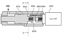
- FIG. 17 which is a sectional view taken along line XX in FIG. 16 and FIG. 16, hydraulic pressure coupled to a parking rod interlocked with a parking lock pawl that can be engaged with a parking ratchet.
- a locking mechanism in which a piston 832 and a cylindrical taper member 858 fitted to a plunger of a solenoid 856 are arranged on the same axis has been proposed (for example, see Patent Document 1).
- FIG. 16 shows a state of the locking mechanism when the parking lock is released.
- the taper member 858 is biased by the spring 859 to the hydraulic piston 832 side (left side in FIG.
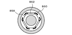
- the claw portion 862 including the three plates 860 provided around the taper member 858. Is expanded by the taper member 858 and the hydraulic piston 832 moves to the left side in FIG. 16 to form a parking lock state.
- the parking lock state when the hydraulic piston 832 is moved to the right side in FIG. 16 by the hydraulic pressure and the taper member 858 is pressed against the urging force of the spring 859, the claw portion 862 closes inward and the hydraulic piston 832 is closed. Further, the position of the taper member 858 is fixed by the solenoid 856, whereby the position of the hydraulic piston 832 is locked and the parking lock release state is formed. With such a configuration, the parking lock release state can be maintained even when the hydraulic pressure of the hydraulic piston device is reduced due to the stop of the engine-driven mechanical pump at the time of idling stop.
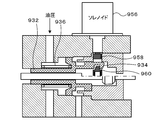
- FIGS. 18 and 19 a parking apparatus has been proposed in which a solenoid or the like is arranged in a direction perpendicular to the axis of the hydraulic piston.
- FIG. 18 shows a state of the locking mechanism of the parking device in the parking lock release state
- FIG. 19 shows a state of the locking mechanism of the parking device in the parking lock state.
- a hook portion 934 is formed at the end of the hydraulic piston 932 and is operated in a direction orthogonal to the direction of the axis of the hydraulic piston 932 by a solenoid 956 attached to the side of the axis of the hydraulic piston 932.
- a claw portion 960 is formed at the end portion of the actuating member 958. Then, when the parking lock is released, the hook 934 is engaged with the hook 934 while the hydraulic piston 932 is moved to the right side in the figure by the hydraulic pressure against the urging force of the spring 936. (See FIG. 19).
- switching from the parking lock state to the parking lock release state is performed by releasing the hydraulic pressure to the hydraulic piston 932 and moving the operating member 958 downward in the figure by the solenoid 956 between the claw portion 960 and the hook portion 934. This is done by releasing the fitting.
- the parking lock release state cannot be switched to the parking lock state.
- the main purpose of the parking device of the present invention is to make the arrangement in a limited space good and to form a parking lock state more appropriately.
- the parking device of the present invention has taken the following means in order to achieve the main object described above.
- the parking apparatus of the present invention A parking device mounted on a vehicle and forming a parking lock state and a parking lock release state, A first shaft member movable in a first direction; a first elastic member that urges the first shaft member toward a lock side that forms the parking lock state in the first direction by an elastic force; and A hydraulic pressure generating unit that moves the first shaft member to the release side opposite to the lock side in the first direction against the elastic force of the first elastic member; A second shaft member movable in a second direction orthogonal to the first direction, and a second elastic member for urging the second shaft member toward the first shaft member in the second direction by an elastic force; A magnetic force holding part capable of holding the second shaft member on the first shaft member side by magnetic force; With The first shaft member is provided with an abutting portion capable of abutting with a distal end portion of the second shaft member, When the second shaft member is not held on the first shaft member side by the magnetic force, the electromagnetic unit moves from the contact portion of the first shaft member to the second shaft when the first shaft
- the hydraulic pressure against the elastic force of the first elastic member acts on the first shaft member when the second shaft member is not held on the first shaft member side by the magnetic force in the parking lock state. Then, the first shaft member moves to the release side while moving the second shaft member to the side away from the first shaft member by the contact between the contact portion of the first shaft member and the tip portion of the second shaft member.
- the parking lock release state is formed.
- the second shaft member is caused by the magnetic force before the hydraulic pressure decreases (for example, before the engine-driven mechanical pump generating the hydraulic pressure is stopped by the idle stop).
- the first shaft member moves to the lock side while moving the second shaft member away from the first shaft member due to contact with the tip of the shaft member, and a parking lock state is formed. Accordingly, when the second shaft member is not held on the first shaft member side by the magnetic force and the hydraulic pressure against the elastic force of the first elastic member is not acting on the first shaft member, the parking lock state is set. It can form more appropriately.
- the hydraulic unit (first shaft member, etc.) and the electromagnetic unit (second shaft member, etc.) are arranged in directions orthogonal to each other, the space is limited compared to those in which both are arranged on the same axis. It is possible to make the arrangement in the good.
- the magnetic force holding portion can hold the second shaft member on the first shaft member side by magnetic force when the coil is energized, and the electromagnetic unit is not energized to the coil.
- the second shaft member moves in the second direction in the second direction by a force that acts on the distal end portion of the second shaft member from the contact portion of the first shaft member. It may be configured to allow movement away from the shaft member. In this case, when the coil is energized, the second shaft member can be held on the first shaft member side by the magnetic force.
- the parking device of the present invention does not move (stroke) the second shaft member in the second direction by energizing the coil, the second shaft member is moved in the second direction by energizing the coil.
- the desired magnetic flux can be made smaller than that to be achieved.
- the number of turns of the coil can be reduced, and the coil can be downsized and the electromagnetic unit can be downsized. Further, when the coil is de-energized, the second shaft member is allowed to move away from the first shaft member.
- the first shaft moves to the lock side with the movement of the second shaft member to the side away from the first shaft member due to the contact between the contact portion of the member and the distal end portion of the second shaft member, and the parking lock A state is formed.
- the parking lock state is more appropriate when the coil is not energized (including when the coil cannot be energized for some reason) and the hydraulic pressure against the elastic force of the first elastic member is not acting on the first shaft member. Can be formed.
- the electromagnetic unit holds the second shaft member and restricts the movement of the first shaft member to the lock side when energizing the coil. You can also.
- the release side release side of the distal end portion of the second shaft member is formed to be inclined toward the release side from the distal end side to the proximal end side of the second shaft member. It can also be.
- the “release side surface” corresponds to a surface that receives a force by contacting the contact portion of the first shaft member when the first shaft member moves to the lock side.
- the spring load of the first elastic member may be set larger than the spring load of the second elastic member.
- the contact portion may be configured as a roller that is rotatable with respect to the first shaft member. If it carries out like this, the frictional resistance at the time of contact
- the electromagnetic unit may include a bearing member that slidably supports the second shaft member. If it carries out like this, the sliding resistance of a 2nd shaft member can be reduced and the movement of a 2nd shaft member can be made smoother.
- the lock side surface on the lock side of the distal end portion of the second shaft member is formed to incline toward the lock side from the distal end side to the proximal end side of the second shaft member.
- the “lock side surface” corresponds to a surface that receives a force by contacting the contact portion of the first shaft member when the first shaft member moves to the release side.
- the first shaft member is formed with a hole portion through which the tip of the second shaft member can enter and penetrates the first shaft member.
- the tip of the member may be located in the hole.
- a parking device of a modification of the present invention is A parking device mounted on a vehicle and forming a parking lock state and a parking lock release state, A first shaft member capable of switching between the parking lock state and the parking lock release state by moving in the first direction by the elastic force or hydraulic pressure of the first elastic member; A second shaft member that moves forward and backward in a second direction orthogonal to the first direction and that can regulate the movement of the first shaft member by abutment between a tip portion and a contact portion provided on the first shaft member. A second elastic member that urges the second shaft member toward the first shaft member in the second direction by an elastic force, and a lock that prevents the second shaft member from retreating from the first shaft member by a magnetic force.
- a magnetic unit comprising: a permanent magnet to be unlocked; and a lock releasing unit that unlocks the second shaft member by the permanent magnet with energization of the coil; With When the coil is energized, the magnetic unit is configured to apply the force acting on the distal end portion of the second shaft member from the contact portion of the first shaft member by the elastic force or hydraulic pressure of the first elastic member.
- the biaxial member is configured to allow the biaxial member to retract from the first axial member. It is characterized by that.
- the first shaft member and the second shaft member of the magnetic unit are arranged to move in directions orthogonal to each other. Therefore, the arrangement in a limited space can be made better than those arranged so that both move in the same direction (on the same axis).
- the second shaft member is locked so as not to retract from the first shaft member by the magnetic force of the permanent magnet.
- the contact portion of the first shaft member and the tip portion of the second shaft member are in contact, the movement of the first shaft member in the first direction is restricted and the parking lock state or the parking lock release state is maintained. can do.
- the unlocking portion unlocks the second shaft member by the permanent magnet, and the elastic force or hydraulic pressure of the first elastic member causes the first shaft member to contact the tip of the second shaft member.
- the second shaft member is allowed to retract from the first shaft member due to the force acting on the portion.
- the first shaft member is moved in the first direction while the second shaft member is retracted from the first shaft member by the elastic force or hydraulic pressure of the first elastic member, and the parking lock state and the parking lock release state are detected. And can be switched.
- power consumption since it is not necessary to energize a coil when holding a parking lock state and a parking lock release state, power consumption can be controlled.
- the permanent magnet is fixed to the second shaft member, and the unlocking portion is formed of a magnetic body and faces the permanent magnet in the second direction.
- the second shaft member may be locked by attraction between the permanent magnet and the facing portion.
- the permanent magnet can be fixed to the second shaft member easily and accurately by adhesion or the like.
- the permanent magnet is fixed to the unlocking portion
- the second shaft member has a magnetic body portion formed of a magnetic body
- the permanent magnet And the magnetic body portion are arranged to face each other in the second direction, and the second shaft member is locked by attraction of the permanent magnet and the magnetic body portion.
- the second shaft member is formed of a shaft formed of a nonmagnetic material and a magnetic material.
- a plunger, and the shaft has a small diameter portion having the tip portion, and an enlarged diameter portion extending from the small diameter portion to the opposite side of the contact portion and having a larger diameter than the small diameter portion,
- the plunger is formed to have a larger diameter than the diameter-expanded portion, and the shaft and the plunger are arranged such that the end surface of the plunger on the first shaft member side is the diameter-expanded portion by the elastic force of the second elastic member.
- the end surface of the enlarged diameter portion is in contact with a part of the unlocking portion, and the tip end portion of the shaft is the first shaft member.
- Cormorant is biased to said first shaft member side, the permanent magnet is disposed so as to surround the outer periphery of the enlarged diameter portion can also be a thing.
- a shaft and a plunger will be integrally urged
- the permanent magnet is arranged so as to surround the outer periphery of the enlarged diameter portion of the shaft, even if the shaft rattles in the radial direction, Can be absorbed by the clearance between.
- the magnetic gap formed on the outer periphery of the plunger can be made smaller than that in which the shaft, the plunger, and the permanent magnet are integrally formed.
- the shaft is formed of a nonmagnetic material, leakage of magnetic flux in the magnetic unit can be reduced. As a result, it is possible to increase the magnetic efficiency while suppressing an increase in size of the magnetic unit.
- the length of the permanent magnet in the second direction is the second length of the enlarged diameter portion. It can also be shorter than the length of the direction.
- the tip end portion of the second shaft member is moved when the first shaft member moves to the lock side where the parking lock state is formed in the first direction.
- a release side that receives a force from the contact portion of the shaft member has a release side, and the release side is formed to be inclined toward the release side from the distal end side to the proximal end side of the second shaft member. Can also be.
- the first shaft member moves from the first shaft member to the second shaft member at the time of contact between the contact portion of the first shaft member and the release side surface of the distal end portion of the second shaft member.
- the second shaft member can be retracted from the first shaft member by the component force in the second direction of the force acting on the first shaft member.
- the tip end portion of the second shaft member is moved when the first shaft member moves to the release side where the parking lock release state in the first direction is formed.
- a lock side surface that receives a force from the contact portion of the first shaft member is formed, and the lock side surface is formed so as to be inclined toward the lock side as it goes from the distal end side to the proximal end side of the second shaft member. It can also be.
- the first shaft member moves to the release side, the first shaft member to the second shaft member at the time of contact between the contact portion of the first shaft member and the lock side surface of the distal end portion of the second shaft member.
- the second shaft member can be retracted from the first shaft member by the component force in the second direction of the force acting on the first shaft member.
- the contact portion may be configured as a roller that can rotate with respect to the first shaft member. If it carries out like this, the frictional resistance between the contact part of a 1st shaft member and the front-end
- the magnetic unit may include a bearing member that slidably supports the second shaft member. If it carries out like this, the movement of the 2nd direction of a 2nd shaft member can be made smoother.
- the first shaft member is formed with a hole portion through which the tip end portion of the second shaft member can enter and penetrates the first shaft member,
- the tip portion of the biaxial member may be located in the hole portion.
- the magnetic unit may be configured such that when the coil is not energized, the magnetic shaft is moved from the contact portion of the first shaft member by the elastic force of the first elastic member.
- the second shaft member is not retracted from the first shaft member by a force acting on the distal end portion, and the hydraulic force resists the elastic force of the first elastic member and the locking force of the second shaft member by the permanent magnet.
- the second shaft member is configured to allow the second shaft member to be retracted from the first shaft member by a force acting on the tip portion of the second shaft member from the contact portion of the first shaft member; You can also
- the first shaft member is biased toward the lock side where the parking lock is formed in the first direction by the elastic force of the first elastic member, and the first elastic member It is also possible to move to the release side where the parking lock release state in the first direction is formed by a hydraulic pressure that resists the elastic force.
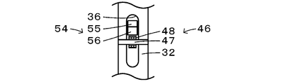
- FIG. 3 is a configuration diagram showing an outline of a configuration of a hole 36 formed in a piston rod 32 of the parking device 20.
- FIG. It is a block diagram which shows the outline of the structure in the parking lock cancellation
- FIG. 6 is an explanatory diagram showing a state when a roller 48 of a pin 46 of a piston rod 32 comes into contact with a lower contact surface 56 of a distal end portion 54 of a solenoid shaft 52.
- FIG. 2 is a configuration diagram showing an outline of a partial configuration of a hydraulic unit 210.
- FIG. 2 is a configuration diagram showing an outline of the configuration of an electromagnetic unit 220.
- FIG. 2 is a configuration diagram showing an outline of a configuration of a lock shaft 221.
- FIG. 6 is an explanatory diagram for explaining the operation of the parking device 201.
- FIG. 6 is an explanatory diagram for explaining the operation of the parking device 201.
- FIG. It is a block diagram which shows the outline of a structure of the electromagnetic unit 320 of a modification. It is a block diagram which shows an example of a structure of the locking mechanism of the parking apparatus as background art. It is sectional drawing of the XX plane of FIG.
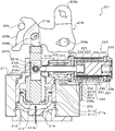
- FIG. 1 is a configuration diagram showing an outline of the configuration of the parking device 20 according to the first embodiment of the present invention in a parking lock state
- FIG. 2 shows the periphery of the hole 36 formed in the piston rod 32 of the parking device 20
- FIG. 3 is a block diagram showing a schematic configuration of the parking device 20 of the first embodiment in a parking lock release state (when the parking lock release state is formed by hydraulic pressure). It is.
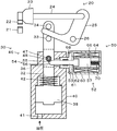
- the parking device 20 of the first embodiment is mounted on a vehicle and, as shown in FIGS. 1 and 3, a parking gear 21 attached to a rotating shaft connected to the axle side, and a pawl that can mesh with the parking gear 21
- a rotation member 25 having one end rotatably attached to the other end of the parking rod 24 and rotating about the rotation shaft 26, and a first direction of the piston rod 32 as the first shaft member
- a hydraulic unit 30 that rotates the rotating member 25 by applying a force to the other end of the rotating member 25 by moving in the vertical direction in the figure, and a second direction orthogonal to the first direction (left and right in the figure).
- An electromagnetic unit (magnetic unit) 50 that restricts movement of the piston rod 32 in the vertical direction in the drawing by holding a solenoid shaft 52 as a second shaft member movable in the direction) by a magnetic force when the coil 64 is energized; Is provided.
- the hydraulic unit 30 includes a piston rod 32 that is attached so that the other end of the rotating member 25 is held by two pins 33 and 34 with a relatively large margin and is movable in the vertical direction in the figure, and a piston rod 32 and a case (cylinder) 40 in which a working oil inlet / outlet hole 41 for accommodating the working oil and introducing the working oil is formed, and the piston 38 is disposed in the case 40 by an elastic force.
- a return spring 42 as an elastic member for urging the lower side (lock side) in the figure.
- the piston 38 (piston rod 32) is moved to the upper side (release side) in the figure by the hydraulic pressure that resists the elastic force of the return spring 42.
- the piston rod 32 is formed with a hole 36 (particularly see FIG. 2) extending in the vertical direction in the figure.
- the hole 36 is formed in the horizontal direction in FIG.
- a pin 46 is provided that crosses in the front-rear direction in FIG.
- the pin 46 includes a cylindrical support shaft (shaft portion) 47 fixed to the piston rod 32, and a roller 48 as a contact portion that is hollow cylindrical and rotatable with respect to the support shaft 47.
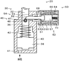
- the electromagnetic unit 50 includes a solenoid shaft 52 that is movable in the left-right direction in the drawings and includes a small-diameter portion 53 and a large-diameter portion 57 having a larger outer diameter, and a large solenoid shaft 52.
- a yoke 60 serving as a case for accommodating the diameter portion 57, a coil 64 disposed on the inner peripheral side of the yoke 60, and a large diameter portion 57 of the solenoid shaft 52 disposed on the inner peripheral side of the coil 64 in the horizontal direction in the figure.
- a spring 70 that biases the solenoid shaft 52 toward the piston rod 32 (left side in the figure) by elastic force.
- the spring load of the spring 70 is set smaller than the spring load of the return spring 42.
- a terminal from the coil 64 is arranged in a connector portion (not shown) formed on the outer peripheral side of the yoke 60, and the coil 64 is energized through this terminal.
- the yoke 60 is formed of a magnetic material, and has an inner diameter smaller than the inner diameter of the coil 64 and the outer diameter of the large-diameter portion 57 of the solenoid shaft 52 at the position on the left side of the coil 64 in the drawing on the inner peripheral side.
- An annular flange portion (projecting portion) 61 projecting radially inward is formed.
- the portion of the solenoid shaft 52 that attracts the magnetic portion formed of the magnetic material is referred to as the attracting portion 62 hereinafter.
- the front end 54 of the solenoid shaft 52 (the left end of the small diameter portion 53 in the drawing) faces the right half of the roller 48 of the pin 46 in the hole 36 of the piston rod 32 in the vertical direction in the drawing. Has been placed.
- the upper surface (release side) in the figure (when the piston rod 32 moves from the state shown in FIG.
- the surface (hereinafter referred to as the upper contact surface 55) is formed so as to incline at a fixed angle from the distal end side toward the proximal end side (from the left side to the right side in the drawing) toward the upper side in the drawing.
- Lower side (lock side) surface (a surface that contacts the roller 48 and receives a force from the roller 48 when the piston rod 32 moves from the state of FIG. 1 to the upper side in the drawing, hereinafter referred to as a lower contact surface 56) Is formed in a curved surface shape having a curvature radius smaller than the curvature radius of the roller 48 from the front end side toward the base end side (a curved surface shape of an arc as viewed from the front side in the drawing).
- the solenoid shaft 52 is formed of a non-magnetic material for the small-diameter portion 53 and a part of the large-diameter portion 57 on the radially inner side, and the remainder of the large-diameter portion 57 is formed of a magnetic material ( It corresponds to the above-mentioned magnetic part).
- the solenoid shaft 52 has a distal end portion 54 that is not in contact with the roller 48 of the pin 46 of the piston rod 32 and is not energized to the coil 64. The middle left surface is pressed against the right surface in the drawing of the suction portion 62 of the yoke 60.
- the solenoid shaft 52 is held on the left side (piston rod 32 side) in the figure ( In the drawing, the movement to the right side (the side away from the piston rod 32) is restricted.)
- the roller 48 of the piston rod 32 moves from the roller 48 of the piston rod 32 to the tip 54 of the solenoid shaft 52.
- the hydraulic unit 30 (piston rod 32, etc.) and the electromagnetic unit 50 (solenoid shaft 52, etc.) are arranged in directions orthogonal to each other. Compared with what to arrange
- the piston rod 32 (roller 48) contacts the solenoid shaft 52 in the diagonally upper right direction in the figure (specifically, the portion of the arcuate curved lower contact surface 56 that contacts the roller 48).
- the solenoid shaft 52 is moved to the right side (the side away from the piston rod 32) in the figure by the lateral force in the figure.
- the piston rod 32 moves upward in the drawing. Then, as shown in FIG.
- the roller 48 that is rotatable with respect to the piston rod 32 (support shaft 47) is used as the contact portion of the piston rod 32, the roller 48 of the piston rod 32 and the tip end portion 54 of the solenoid shaft 52 are connected.
- the frictional resistance at the time of contact can be reduced, the wear can be suppressed, and the movement of the piston rod 32 and the solenoid shaft 52 can be made smoother.
- the piston rod 32 is held by the bearing member 68, the sliding resistance of the solenoid shaft 52 can be reduced, and the movement thereof can be made smoother.
- the lower contact surface 56 is formed in a curved surface having a smaller radius of curvature than the radius of curvature of the roller 48, the right side force in the figure acting on the solenoid shaft 32 as the piston rod 32 moves upward in the figure. Easy to grow. Therefore, even when the hydraulic pressure is slightly low, the piston rod 32 can move upward in the drawing while moving the solenoid shaft 52 to the right in the drawing.
- the roller 48 of the pin 46 of the piston rod 32 contacts the upper contact surface 55 of the tip 54 of the solenoid shaft 52, and the piston rod 32 is held at that position. Thereby, even when the hydraulic pressure to the piston 38 decreases, the parking lock release state can be maintained.
- the electromagnetic unit 50 of the first embodiment attracts and holds the solenoid shaft 52 toward the suction portion 62 when the coil 64 is energized, the solenoid shaft 52 is moved in the second direction (the left-right direction in the figure).
- the desired magnetic flux can be reduced as compared with the case of moving to ().
- the number of turns of the coil 64 necessary to obtain a desired magnetic flux can be reduced, and the coil 64 and the electromagnetic unit 50 can be downsized.
- the piston rod 32 moves to a position where the roller 48 does not contact the tip portion 54 of the solenoid shaft 52. In this way, switching to the parking lock state is performed. Therefore, when the coil 64 is not energized (including when the coil 64 cannot be energized for some reason) and the hydraulic pressure against the elastic force of the return spring 42 is not acting on the piston rod 32, the parking lock state is more appropriately set. Can be formed. Further, as described above, the roller 48 and the bearing member 68 suppress wear of the roller 48 of the piston rod 32 and the tip end portion 54 of the solenoid shaft 52 in the same manner as when switching from the parking lock state to the parking lock release state. In addition, the movement of the piston rod 32 and the solenoid shaft 52 can be made smoother.
- the solenoid shaft 52 when the coil 64 is energized, the solenoid shaft 52 is held (movement is restricted), and when the coil 64 is not energized, the piston rod 32 moves.
- the electromagnetic unit 50 is configured to allow the solenoid shaft 52 to move away from the piston rod 32 by the force acting on the tip portion 54 of the solenoid shaft 52 from the roller 48 of the pin 46 of the piston rod 32.
- the parking lock release state when the coil 64 is de-energized and the hydraulic pressure to the piston 38 is reduced, the contact between the roller 48 of the pin 46 of the piston rod 32 and the tip 54 of the solenoid shaft 52 causes the solenoid shaft 52 to move.
- the piston rod 32 moves to the lock side while being moved away from the piston rod 32, thereby forming a parking lock state. Accordingly, when the coil 64 is not energized (including when the coil 64 cannot be energized for some reason) and the hydraulic pressure against the elastic force of the return spring 42 is not acting on the piston rod 32, the parking lock state is more appropriate. Can be formed.
- the roller 48 that is rotatable with respect to the piston rod 32 (support shaft 47) is used as the contact portion of the piston rod 32, and the solenoid shaft 62 is moved by the bearing member 68. Since it is slidably supported in two directions, it is possible to suppress wear of the roller 48 of the piston rod 32 and the tip end portion 54 of the solenoid shaft 52 when switching between the parking lock state and the parking lock release state. The movement of 32 and the solenoid shaft 52 can be made smoother.
- the roller 48 that can rotate with respect to the piston rod 32 (support shaft 47) is used as the contact portion of the piston rod 32. (For example, the same as the support shaft 47) may be used.
- the frictional resistance between the contact portion of the piston rod 32 and the tip portion 54 of the solenoid shaft 52 increases. Therefore, the movement of the piston rod 32 and the movement of the solenoid shaft 52 when switching between the parking lock state and the parking lock release state may be slightly reduced in smoothness. It can be made easier to hold.
- the electromagnetic unit 50 includes the bearing member 68 that slidably supports the small diameter portion 53 of the solenoid shaft 52.
- the electromagnetic unit 50 may not include the bearing member 68. .
- the lower contact surface 56 of the distal end portion 54 of the solenoid shaft 52 is convex downward in the figure from the distal end side toward the proximal end side, and the radius of curvature of the roller 48 of the pin 46 is increased.
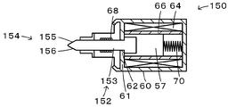
- it is formed as a curved surface having a smaller radius of curvature, it may be formed as a curved surface having a radius of curvature equal to or greater than the radius of curvature of the roller 48, or the electromagnetic unit 150 of the modified example of FIG.
- the lower contact surface 156 of the distal end 154 of the small diameter portion 153 of the solenoid shaft 152 is formed so as to be inclined at a constant angle from the distal end side toward the proximal end side in the figure. It is good.
- the upper contact surface 55 of the distal end portion 54 of the solenoid shaft 52 is inclined at a constant angle from the distal end side toward the proximal end side in FIG. 1 or FIG. 3 (release side).
- the present invention is not limited to a certain angle, and may be formed so as to be inclined at a smoothly changing angle.
- the roller 48 of the pin 46 of the piston rod 32 and the lower contact surface 56 of the tip 54 of the solenoid shaft 52 are in contact with each other in the parking lock state. Although it shall not touch, it is good also as what touches. In this way, when switching to the parking lock release state, the movement amount of the piston rod 46 to the release side can be shortened, and the collision between the roller 48 and the lower contact surface 56 can be suppressed. it can.
- the piston rod 32 is moved downward by the elastic force of the return spring 42 in FIG.
- the working oil may be supplied through the working oil inlet / outlet. In this way, the piston rod 32 can be moved more quickly in the lower side in FIG. 3 by the elastic force and hydraulic pressure of the return spring 42.
- FIG. 8 is a configuration diagram showing an outline of the configuration of the parking apparatus 201 as the second embodiment of the present invention
- FIG. 9 is a configuration diagram showing an outline of the configuration of the main part of the parking apparatus 201.
- FIG. 11 is a configuration diagram showing a schematic configuration of a part of the hydraulic unit 210
- FIG. 11 is a configuration diagram showing a schematic configuration of the electromagnetic unit 220
- FIG. 12 is a configuration of the lock shaft 221 of the electromagnetic unit 220. It is a block diagram which shows the outline of this.
- the parking device 201 of the second embodiment is mounted on a vehicle and is disposed inside or outside a transmission case of a transmission (not shown).
- the parking device 201 is a so-called shift-by-wire system that locks and unlocks one of the rotary shafts of the transmission based on an electric signal output in accordance with an operation position (shift range) of a shift lever (not shown). It is configured as a parking device of the type.
- the parking device 201 has a plurality of teeth 202 a and a parking gear 202 that is attached to one of the rotation shafts of the transmission, and a protrusion 203 a that can be engaged with the parking gear 202.
- a parking pole 203 that is urged away from the parking gear 202 by a spring that does not move, a parking rod 204 that can move forward and backward, a cylindrical cam member 205 that can move in the axial direction of the parking rod 204, and a transmission case, for example.
- a support roller 206 that is rotatably supported and holds the cam member 205 together with the parking pole 203, and a cam that biases the cam member 205 so that one end is supported by the parking rod 204 and the parking pole 203 is pressed against the parking gear 202.
- the spring 207 By restricting the movement of the spring 207, the detent lever 208 connected to the parking rod 204, the hydraulic unit 210 that moves the parking rod 204 forward and backward through the detent lever 208 by the movement of the piston rod 212, and the movement of the piston rod 212 And an electromagnetic unit (magnetic unit) 220 that restricts the forward / backward movement of the parking rod 204.
- the protrusion 203a of the parking pole 203 engages with the recess between two adjacent teeth 202a of the parking gear 202, so that the rotation shaft of the transmission is locked ( Parking lock is performed).
- the parking gear 202, the parking pole 203, the parking rod 204, the cam member 205, the support roller 206, and the cam spring 207 all have a known configuration.
- the detent lever 208 is formed in a substantially L shape, and has a first free end 208a and a second free end 208b.
- the first free end 208a is rotatably connected to the base end (the right end in FIG. 8) of the parking rod 204.
- the second free end 208b is formed with an engagement recess 208r that can engage with an engagement member 209 attached to a detent spring (not shown) supported by a transmission case, for example.
- a corner portion of the detent lever 208 (base end portions of the first and second free end portions 208a and 208b) is rotatably supported by a support shaft 208s supported by, for example, a transmission case.
- the hydraulic unit 210 is configured to operate by hydraulic pressure from a hydraulic control device of a transmission that is controlled by an electronic control device based on an electric signal output in accordance with an operation position (shift range) of a shift lever. As shown in FIG. 9, the hydraulic unit 210 is connected to a case 211 composed of a plurality of members and a second free end portion 208b of the detent lever 208 and is axially moved by the case 211 (up and down direction in FIG. 9). (Piston rod 212 as a first shaft member supported movably in (first direction)), piston 214 fixed in piston rod 212 and disposed in piston chamber 211p formed in case 211, Is provided.
- the piston rod 212 is supported by the case 211 so that the tip end portion (the upper end portion in FIG. 9) protrudes from the case 211 to the outside.
- a connecting concave portion 212r extending from the distal end side toward the proximal end side is formed at the distal end portion of the piston rod 212.
- the second concave portion 212r of the detent lever 208 is formed in the connecting concave portion 212r. The end 208b is inserted.
- An elongated hole 208h is formed in the detent lever 208 so as to be positioned in the coupling recess 212r, and a coupling pin 212p supported by the tip of the piston rod 212 is inserted into the elongated hole 208h.
- the long hole 208h is formed so that a space is defined between the inner periphery thereof and the outer peripheral surface of the connecting pin 212p.
- a hole 212h that penetrates the piston rod 212 in a direction orthogonal to the axial direction (left-right direction in FIG. 9) and extends in the axial direction is formed near the central portion in the axial direction of the piston rod 212.
- a roller 213 as a contact portion is disposed inside the hole portion 212h.
- the roller 213 is configured as a roller bearing, and has an outer diameter smaller than the length of the hole 212h in the longitudinal direction (vertical direction in FIGS. 9 and 10).
- the roller 213 is supported so as to be rotatable in the hole 212h by a support shaft 212s supported by the piston rod 212 so as to extend in parallel with the connecting pin 212p.
- the piston 214 is fixed to the base end portion (lower end portion in FIG. 9) of the piston rod 212, and is supported by the inner wall surface of the piston chamber 211p via the seal member 215 so as to be movable in the axial direction of the piston rod 212.
- the piston 214 partitions the inside of the piston chamber 211p into an oil chamber 211f and a spring chamber 211s.
- the oil chamber 211f is defined on the lower side in FIG. 9 of the piston chamber 211p so as to be separated from the tip end portion (upper end portion in FIG. 9) of the piston rod 212 and the detent lever 208, and is filled with hydraulic oil formed in the case 211. It communicates with the drain hole (oil hole) 211h.
- the oil chamber 211f is supplied with hydraulic pressure (hydraulic oil) from the hydraulic control device via an oil passage (not shown) and a hydraulic oil inlet / outlet hole 211h.
- the spring chamber 211s is defined on the upper side in FIG. 9 of the piston chamber 211p so as to be close to the tip of the piston rod 212 and the detent lever 208.
- a return spring 216 as an elastic member is disposed in the spring chamber 211s so as to be positioned between the case 211 and the piston 214. The piston 214 is moved from the spring chamber 211s side to the oil chamber 211f side by the return spring 216. (Downward in the figure).
- the hydraulic unit 210 configured in this manner is in the assembled state (the state when the assembly is completed), and the piston 214 is urged downward in FIG. The amount of protrusion from the case 211 is minimized.
- the parking rod 204 connected to the piston rod 212 via the detent lever 208 comes closest to the base end of the parking pole 203, and the parking pole 203 is moved to the parking gear by the cam member 205 biased by the cam spring 207. It is pressed so as to engage with 202, and the rotation shaft of the transmission is locked (parking lock is performed).
- the hydraulic pressure supply from the hydraulic control device to the hydraulic oil inlet / outlet hole 211h is cut off, and the hydraulic oil enters the hydraulic chamber 211f.
- the piston 214 moves downward in FIG. 8 in the moving direction of the piston rod 212 (hereinafter referred to as “lock side” as appropriate) by the elastic force of the return spring 216.
- the piston rod 212 fixed to the piston 214 also moves to the lock side, and accordingly, the detent lever 208 rotates about the support shaft 208s counterclockwise in FIG. 8 and the parking rod 204 in FIG. Move to the left.
- the cam pole 205 When the parking rod 204 moves to the left in FIG. 8, the cam pole 205 is pressed by the cam member 205 urged by the cam spring 207 so as to engage the parking gear 202, and the rotation shaft of the transmission is Locked (parking lock is performed).
- the engagement recess 208r of the second free end 208b of the detent lever 208 engages with the engagement member 209, so that the rotation of the detent lever 208 around the support shaft 208s is restricted to some extent by a detent spring (not shown). Thereby, the movement of the parking rod 204 is also restricted to some extent.
- the electromagnetic unit 220 is a return spring when the hydraulic pressure supplied to the oil chamber 211f of the hydraulic unit 210 decreases as the vehicle engine and the oil pump driven by the engine are stopped, for example, by idle stop. It is used to restrict the piston rod 212 from moving to the lock side by the elastic force (biasing force) 216 and to prevent the parking lock from being released to the parking lock state.
- the electromagnetic unit 220 includes a lock shaft 221 having a tip 2210 that can be brought into contact with a roller 213 (see FIG. 9) as a contact provided on the piston rod 212, and a lock shaft 221. Is provided with a shaft holder 225 movably supported in the axial direction (left and right direction (second direction in FIG. 11)), and a magnetic part 230 capable of locking the lock shaft 221 by magnetic force.
- the lock shaft 221 is formed of a non-magnetic material such as stainless steel, and as shown in FIGS. 11 and 12, extends from the small diameter portion 222 to the opposite side of the distal end portion 2210. And an enlarged diameter part 223 having a larger diameter than the small diameter part 222.
- the small-diameter portion 222 is formed in a substantially cylindrical shape, and the tip portion 2210 is formed so as to have a two-sided width shape.
- the enlarged diameter portion 223 is formed in a substantially cylindrical shape, and has an annular end surface 223a on the small diameter portion 222 side and a flat end surface 223b on the opposite side to the small diameter portion 222 side.
- a tapered portion 222t is formed on the outer peripheral surface of the small diameter portion 222 in the vicinity of the boundary between the small diameter portion 222 and the large diameter portion 223.
- the tapered portion 222t is formed in the vicinity of the boundary with the enlarged diameter portion 223 such that the outer peripheral surface of the smaller diameter portion 222 tapers from the distal end portion 2210 side toward the end surface 223a side of the enlarged diameter portion 223 (the outer diameter decreases).
- the distal end portion 2210 of the small diameter portion 222 has a lower contact surface 2211 located on the lock side (lower side in the drawing) in the moving direction of the piston rod 212 (up and down direction in FIGS. 11 and 12), and the movement of the piston rod 212. And an upper contact surface 2212 located on the release side (upper side in the drawing) in the direction.
- the lower contact surface 2211 is formed so as to incline toward the lock side as it goes from the distal end portion 2210 side to the enlarged diameter portion 223 side, and specifically, is smaller than the radius (curvature radius) of the outer peripheral surface of the roller 213. It is formed as a curved surface having an arcuate cross section that has a radius of curvature and is convex on the lock side.
- the upper contact surface 2212 is formed so as to incline toward the release side as it goes from the distal end portion 2210 side to the diameter-enlarged portion 223 side, and specifically, as an inclined surface that is inclined (flat) at a constant angle toward the release side. Is formed.
- the shaft holder 225 is formed in a substantially bottomed cylindrical shape by a nonmagnetic material such as aluminum, and is held by the magnetic unit 230.
- a hole through which the small-diameter portion 222 of the lock shaft 221 is inserted is formed at the bottom of the shaft holder 225, and the tip 2210 of the small-diameter portion 222 of the lock shaft 221 protrudes from the shaft holder 225 to the left side in the drawing.
- a bearing member (linear motion bearing) 227 that slidably supports the outer peripheral surface of the small diameter portion 222 is fixed inside the shaft holder 225.
- the lock shaft 221 can be smoothly moved in the axial direction while suppressing the play of the lock shaft 221. Further, an annular flange portion 225a protruding outward in the radial direction is formed at the right end portion of the shaft holder 225 in the drawing.
- the magnetic unit 230 is disposed so as to surround the outer periphery of the shaft moving member 231 and the shaft moving member 231 that can move in the axial direction (left and right direction (second direction) in the drawing) together with the lock shaft 221.
- the shaft moving member 231 has a plunger 232 formed of a magnetic material such as iron, and has the same outer diameter as the plunger 232 and is fixed to one end side (left end side in the figure) of the plunger 232 in the axial direction (plunger 232). And an annular permanent magnet 233 configured integrally. By fixing the permanent magnet 233 to the plunger 232 by bonding or integral molding, it can be easily and accurately performed.
- the shaft moving member 231 has a recess 2310 formed on one end side in the axial direction, and a flat and annular end surface 231a around the recess 2310. The end surface 231 a is formed as an end surface on one end side of the permanent magnet 233.
- the concave portion 2310 is a circular hole portion having a bottom surface 2310 b and an inner peripheral surface in a direction orthogonal to the axial direction.
- the bottom surface 2310 b is formed as an end surface on one end side of the plunger 232, and the inner peripheral surface is the permanent magnet 233. It is formed as an inner peripheral surface.
- the enlarged diameter portion 223 of the lock shaft 221 is inserted so that the end surface 223b of the enlarged diameter portion 223 of the lock shaft 221 contacts the bottom surface 2310b.
- the depth of the concave portion 2310 of the shaft moving member 231 (the axial length of the permanent magnet 233) is set to a value slightly shallower (for example, about 0.1 mm) than the axial length of the enlarged diameter portion 223 of the lock shaft 221. It has been. Therefore, the end surface 223a of the diameter-enlarged portion 223 of the lock shaft 221 inserted into the recess 2310 protrudes outward (left side in the drawing) from the end surface 231a of the shaft moving member 231.
- the inner diameter of the inner peripheral surface of the recess 2310 of the shaft moving member 231 (the inner diameter of the permanent magnet 233) is slightly larger (for example, about 0.5 mm to 1 mm) than the outer diameter of the enlarged diameter portion 223 of the lock shaft 221. It has been established. Therefore, a predetermined clearance is formed between the inner peripheral surface of the recess 2310 (permanent magnet 233) and the outer peripheral surface of the enlarged diameter portion 223 of the lock shaft 221 inserted into the recess 2310.
- the shaft moving member 231 has a diameter. It is possible to suppress backlash in the direction. As a result, the magnetic gap between the shaft moving member 231 (plunger 232) and the core 236 can be reduced. Further, as described above, since the lock shaft 221 is formed of a nonmagnetic material, magnetic flux leakage in the electromagnetic unit 220 can be reduced. As a result, the magnetic efficiency can be increased while suppressing an increase in size of the magnetic unit 230.
- the axial length of the enlarged diameter portion 223 and the shaft are determined by the clearance between the outer circumferential surface of the enlarged diameter portion 223 and the inner circumferential surface of the recess 2310 of the shaft moving member 231 (the inner circumferential surface of the permanent magnet 233).
- the difference between the depth of the recess 2310 of the moving member 231 (the length of the permanent magnet 233 in the second direction) is set to a small value.
- the coil 234 has a terminal connected to a connector (not shown) attached to a yoke 235 as a case.
- a current is applied to the coil 234 from an auxiliary battery of a vehicle (not shown) through an electronic control device that controls the hydraulic control device and a power supply circuit and connector that are controlled by another electronic control device.
- the yoke 235 is formed in a substantially cylindrical shape by a magnetic material such as iron, and protrudes radially inward on one end side (left end side in the drawing) and an annular flange portion 235a and the left end in the drawing of the flange portion 235a.
- a holder holding portion 235b that holds the shaft holder 225 is formed by the surface.
- the inner diameter of the flange portion 235a is set to a value smaller than the inner diameter of the permanent magnet 233 of the shaft moving member 231 and the small diameter portion 222 of the lock shaft 221 can slide. That is, the flange portion 235a has a portion on the inner side in the radial direction from the inner diameter of the core 236 facing the end surface 223a on the small diameter portion 222 side of the enlarged diameter portion 223 of the lock shaft 221 and the permanent magnet 233 in the left-right direction in the figure. .
- the lock shaft 221 and the shaft moving member 231 are integrated with the shaft holder 225 side (in the drawing) by the attractive force between the permanent magnet 233 of the shaft moving member 231 and the flange portion 235a of the yoke 235.
- the magnetic flux passing through the yoke 235, the permanent magnet 233, the plunger 232, and the core 236 cancels the attraction between the permanent magnet 233 and the flange portion 235a.
- the lock shaft 221 is made of a nonmagnetic material, magnetic flux leakage in the electromagnetic unit 220 can be reduced.
- the holder support portion 235b is formed so as to cover the outer periphery of the flange portion 225a of the shaft holder 225 and the left end surface in the drawing.
- the yoke 235 is supported (fixed to the case 211) by a support member 239 attached to the case 211.
- a rear cap 238 is attached to the other end portion (right end portion in FIG. 11) of the yoke 235 so as to hold the coil 234 and the core 236, and the end portion of the shaft moving member 231 opposite to the concave portion 2310 side.
- a spring 237 is arranged between the (right end in the figure) and the rear cap 238.
- the spring 237 integrally biases the lock shaft 221 and the shaft moving member 231 that are not fixed to each other toward the shaft holder 225 side (left side in the figure).
- the spring 237 has a spring constant (rigidity) smaller than the return spring 216 of the hydraulic unit 210.
- the sum of the attractive force of the permanent magnet 233 and the flange portion 235a of the yoke 235 and the elastic force of the spring 237 (the force acting on the lock shaft 221 and the shaft moving member 231 in the left direction in the figure) is the return of the hydraulic unit 210.
- 11 is determined so as to be larger than the rightward component force in FIG. 11 (hereinafter referred to as return spring component force).
- the yoke 235 since the yoke 235 is fixed to the case 211 via the support member 239, a large force acts between the holder support portion 235b and the flange portion 225a of the shaft holder 225. Therefore, the yoke 235 and the shaft holder 225 can be further protected.
- the maximum stroke amount Smax in the axial direction of the shaft moving member 231 (plunger 232) in the yoke 235 (in the example of FIG. 11, the right end surface of the shaft moving member 231 (plunger 232) and the inner bottom surface of the rear cap 238).
- the electromagnetic unit 220 configured in this manner is in an assembled state (a state when the assembly is completed), that is, a state before being attached to the hydraulic unit 210, and the elastic force of the spring 237 (and the attraction between the permanent magnet 233 and the flange portion 235a of the yoke 235). Force)), the bottom surface 2310b of the recess 2310 of the shaft moving member 231 (the end surface on one end side of the plunger 232) abuts on the end surface 223b of the expanded diameter portion 223 of the lock shaft 221, and the end surface 223a of the expanded diameter portion 223 is It is urged to contact the flange portion 235a.
- the axial length of the enlarged diameter portion 223 is determined by the clearance between the outer circumferential surface of the enlarged diameter portion 223 and the inner circumferential surface of the recess 2310 of the shaft moving member 231 (the inner circumferential surface of the permanent magnet 233).
- the depth of the recess 2310 of the shaft moving member 231 (the length of the permanent magnet 233 in the second direction) is set to a small value. Accordingly, the distance between the flange portion 235a and the permanent magnet 233 at the time of contact between the enlarged diameter portion 223 and the flange portion 235a is reduced while absorbing the backlash in the radial direction of the lock shaft 221, thereby increasing the attractive force between the two. can do. Further, since the gap between the flange portion 235a and the permanent magnet 233 is small, a magnetic flux for canceling the attraction between the permanent magnet 233 and the flange portion 235a can be generated more efficiently when the coil 234 is energized.
- the tapered portion 222t is formed in the vicinity of the boundary with the enlarged diameter portion 223 in the small diameter portion 222 of the lock shaft 221, the contact range of the end surface 223a of the enlarged diameter portion 223 with the flange portion 235a is as small as possible.
- the electromagnetic unit 220 can be made compact by suppressing an increase in the outer diameter of the enlarged diameter portion 223.
- the electromagnetic unit 220 includes the axial direction of the piston rod 212 of the hydraulic unit 210 (the vertical direction in the drawing (see the dashed line in FIG. 8)), the lock shaft 221 and the shaft moving member 231.
- the electromagnetic unit 220 is attached to the hydraulic unit 210 so that the axial direction (left-right direction in the figure (see the two-dot chain line in FIG. 8)) is orthogonal.
- the hydraulic unit 210 and the electromagnetic unit 220 can be easily arrange
- the tip 2210 (the lower contact surface 2211 and the upper contact surface 2212) of the lock shaft 221 is viewed from the axial direction of the piston rod 212 (see FIG. 9, which overlaps at least a part of the outer peripheral surface of the roller 213.
- the lower contact surface 2211 of the tip 2210 of the lock shaft 221 contacts the outer peripheral surface of the roller 213 (lower contact surface 2211). Is attached to the case 211 of the hydraulic unit 210 so as to receive a force from the roller 213.
- the axial force (forced force) of the lock shaft 221 from the roller 213 of the piston rod 212 acts on the distal end portion 2210 (lower contact surface 2211) of the lock shaft 221, thereby the electromagnetic unit 220.
- the lock shaft 221 and the shaft moving member 231 slightly move toward the rear cap 238 (right side in the figure) against the elastic force of the spring 237. Therefore, a slight gap is formed between the end surface 223a of the enlarged diameter portion 223 of the lock shaft 221 on the small diameter portion 222 side and the flange portion 235a of the yoke 235.
- FIG. 9 shows a state in which the rotation shaft of the transmission is locked by the parking device 201 (parking lock is performed).
- the lock shaft 221 and the shaft moving member 231 are attached to the left side in the drawing by the attractive force of the permanent magnet 233 of the shaft moving member 231 and the flange portion 235a of the yoke 235 and the elastic force of the spring 237. It is energized (locked). At this time, the roller 213 is in contact with the lower contact surface 2211 of the tip 2210 of the lock shaft 221.
- the detent lever 208 rotates around the support shaft 208s in the clockwise direction in FIG. 8 while the piston rod 212 starts to move to the release side due to the hydraulic pressure and then stops.
- the rod 204 moves to the right side in FIG. Thereby, with the movement of the parking rod 204, the pressing of the parking pole 203 by the cam member 205 is released, and the parking lock is released.
- the parking lock release state is thus formed, energization of the coil 234 is terminated.
- the piston rod 212 when the piston rod 212 moves to the release side by hydraulic pressure, the attractive force between the permanent magnet 233 and the flange portion 235a of the yoke 235 is canceled by energizing the coil 234 of the magnetic portion 230.
- the lock shaft 221 and the shaft moving member 231 are moved backward from the piston rod 212 (moved toward the rear cap 238) by the roller 213 of the piston rod 212, as compared with the case where the coil 234 is not energized at this time.
- the required force can be reduced.
- the piston rod 212 can be quickly moved to the release side (the upper side in FIG. 13), or the hydraulic pressure required for the movement of the piston rod 212 to the release side can be reduced.
- the roller 213 of the piston rod 212 is in contact with the lower contact surface 2211 of the lock shaft 221 in the parking lock state shown in FIG.
- the parking device 201 can be made compact by reducing the moving stroke of the piston rod 212 as compared with the configuration in which the roller 213 does not contact the lower contact surface 2211 of the lock shaft 221 in the parking lock state. it can.
- the parking lock state can be promptly shifted to the parking lock release state.
- the roller 213 and the lower contact surface 2211 do not collide, thereby improving the durability of the lock shaft 221 and the roller 213 and generating noise. Can be suppressed.
- the lower contact surface 2211 that receives the force from the roller 213 when the piston rod 212 moves to the release side by hydraulic pressure has a curvature radius smaller than the radius (curvature radius) of the outer peripheral surface of the roller 213. .
- the axial force acting on the lock shaft 221 from the roller 213 when the piston rod 212 moves to the release side can be further increased. It is possible to suppress an increase in the hydraulic pressure that should be supplied to the oil chamber 211f of the hydraulic unit 210 when releasing.
- roller 213 as the contact portion is rotatably supported by the piston rod 212 so that the roller 213 can roll on the lower contact surface 2211 and the upper contact surface 2212, so that the roller 213 can be in contact with the lower contact surface.
- the frictional resistance between the surface 2211 and the upper contact surface 2212 can be reduced, and the wear resistance (durability) of both can be improved.
- the lock shaft 221 and the shaft moving member 231 are configured such that the upper contact surface 2212 of the distal end portion 2210 of the lock shaft 221 is a piston by the attractive force of the permanent magnet 233 and the flange portion 235a of the yoke 235 and the elastic force of the spring 237.
- the rod 212 protrudes into the hole 212 h so as to overlap a part of the outer peripheral surface of the roller 213 when viewed from the axial direction of the rod 212, and the end surface 223 a on the small diameter portion 222 side of the enlarged diameter portion 223 of the lock shaft 221 is the flange portion 235 a of the yoke 235. It is pressed against.
- the depth of the concave portion 2310 of the shaft moving member 231 (the axial length of the permanent magnet 233) is shallower than the axial length of the enlarged diameter portion 223 of the lock shaft 221.
- the end surface 231a of the shaft moving member 231 (permanent magnet 233) does not contact the flange portion 235a.
- the permanent magnet 233 can be protected compared with what the permanent magnet 233 contact
- the parking lock release state can be maintained even when the hydraulic pressure to the hydraulic unit 210 decreases due to execution of idle stop or the like.
- the end surface 223a of the enlarged diameter portion 223 of the lock shaft 221 is pressed against the flange portion 235a of the yoke 235, whereby the distance between the shaft moving member 231 (permanent magnet 233) and the flange portion 235a is increased.
- the lock shaft 221 and the shaft moving member 231 are held with a relatively large holding force. Can be regulated). In addition, since it is not necessary to apply a current to the coil 234 at this time, power consumption can be suppressed and the parking lock release state can be maintained even when the coil 234 cannot be energized for some reason.
- the permanent magnet 233 and the yoke 235 are provided.
- the magnetic flux for canceling the attractive force with the flange portion 235a can be generated more efficiently.
- the spring constant of the spring 237 is smaller than the spring constant of the return spring 216. Therefore, when the hydraulic pressure to the oil chamber 211f of the hydraulic unit 210 decreases while the coil 234 is energized, the hydraulic oil flows out from the oil chamber 211f through the hydraulic oil inlet / outlet hole 211h, and the piston 214 and the piston rod 212 are returned.
- the detent lever 208 rotates around the support shaft 208s counterclockwise in FIG. 8 until the piston rod 212 starts moving to the lock side by the elastic force of the return spring 216 and stops. While rotating, the parking rod 204 moves to the left in FIG. Accordingly, the parking pole 203 is pressed to engage with the parking gear 202 by the cam member 205 biased by the cam spring 207 as the parking rod 204 moves, and the parking lock is performed.
- the roller 213 rolls on the lower contact surface 2211 and the upper contact surface 2212 as in the case of moving to the release side.
- the frictional resistance between the contact surface 2211 and the upper contact surface 2212 can be reduced to improve the wear resistance (durability) of both.
- the moving direction of the lock shaft 221 and the shaft moving member 231 (plunger 232 and permanent magnet 233) of the electromagnetic unit 220 is orthogonal to the moving direction of the piston rod 212 of the hydraulic unit 210.
- the electromagnetic unit 220 is arranged (attached to the hydraulic unit 210). Thereby, compared with what is arrange
- the lock shaft 221 and the shaft moving member 231 are moved by the attractive force between the permanent magnet 233 and the flange portion 235a of the yoke 235.
- the piston rod 212 is locked so as not to move backward, and the movement of the piston rod 212 to the lock side (switching to the parking lock state) by the elastic force of the return spring 216 is restricted.
- the permanent magnet 233 is fixed to the plunger 232 to form the shaft moving member 231 and the axial length of the permanent magnet 233 is the axial direction of the diameter-enlarged portion 223 of the lock shaft 221. It is formed shorter than the length of.
- the lock shaft 221 and the shaft moving member 231 are moved into the recess 2310 of the shaft moving member 231 by the elastic force of the spring 237 (and the attraction between the permanent magnet 233 and the flange portion 235a of the yoke 235).
- the bottom surface 2310b (the end surface on one end side of the plunger 232) is in contact with the end surface 223b of the expanded diameter portion 223 of the lock shaft 221, and the end surface 223a of the expanded diameter portion 223 is urged to contact the flange portion 235a of the yoke 235.
- the lock shaft 221 and the shaft moving member 231 are integrally biased toward the piston rod 212 and the end surface 223a of the enlarged diameter portion 223 of the lock shaft 221 contacts the flange portion 235a. It is possible to suppress backlash in the direction.
- the enlarged diameter portion 223 of the lock shaft 221 is inserted into the recess 2310 of the shaft moving member 231 (the permanent magnet 233 is positioned so as to surround the outer circumference of the enlarged diameter portion 223).
- the backlash can be absorbed by the clearance between the outer peripheral surface of the enlarged diameter portion 223 and the inner peripheral surface of the permanent magnet 233.
- the magnetic gap formed on the outer periphery of the plunger 232 can be reduced.
- the lock shaft 221 is formed of a non-magnetic material, magnetic flux leakage in the electromagnetic unit 220 can be reduced. As a result, it is possible to increase the magnetic efficiency at the time of applying a current to the coil 234 while suppressing an increase in the size of the electromagnetic unit 220.
- the coil 234 in the parking lock release state, the coil 234 is energized to cancel the attractive force between the permanent magnet 233 and the flange portion 235a of the yoke 235, and the hydraulic pressure to the oil chamber 211f of the hydraulic unit 210 is reduced.
- the piston rod 212 moves to the lock side while moving the lock shaft 221 and the shaft moving member 231 backward (moving to the rear cap 238 side) due to the elastic force of the return spring 216.
- the hydraulic pressure (hydraulic oil) from the hydraulic control device may be supplied to the spring chamber 211 s of the hydraulic unit 210. In this way, the piston rod 212 can be moved more quickly on the lock side.
- the coil 234 of the magnetic unit 230 is energized while canceling the attractive force between the permanent magnet 233 and the flange portion 235a.
- the piston rod 212 may be moved to the release side by hydraulic pressure without energizing the coil 234.
- the force acting against the elastic force of the return spring 216 and acting on the lower contact surface 2211 of the lock shaft 221 from the roller 213 of the piston rod 212 is directed to the right in FIG.
- the diameter-enlarged portion is determined by the clearance between the outer peripheral surface of the enlarged-diameter portion 223 of the lock shaft 221 and the inner peripheral surface of the concave portion 2310 of the shaft moving member 231 (the inner peripheral surface of the permanent magnet 233).
- the difference between the axial length of 223 and the depth of the concave portion 2310 of the shaft moving member 231 (the length of the permanent magnet 233 in the second direction) is small, both may be set to the same extent.
- the clearance between the outer peripheral surface of the enlarged diameter portion 223 of the lock shaft 221 and the inner peripheral surface of the concave portion 2310 of the shaft moving member 231 is determined by the axial length of the enlarged diameter portion 223 and the depth of the concave portion 2310 of the shaft moving member 231. It may be smaller than the difference.
- the length of the permanent magnet 233 in the axial direction is shorter than the axial length of the enlarged diameter portion 223 of the lock shaft 221. It is good also as what is formed in the length same as the length of the axial direction of the enlarged diameter part 223 of the lock shaft 221.
- the permanent magnet 233 of the magnetic unit 230 is fixed to the plunger 232 (configured integrally with the plunger 232).
- the permanent magnet 333 of the magnetic part 330 may be fixed to the flange part 235a of the yoke 235.
- the lock shaft 221 and the plunger 232 are integrally biased (locked) toward the shaft holder 225 by the attractive force between the permanent magnet 333 and the plunger 232.
- the length of the permanent magnet 333 in the axial direction (left-right direction in the figure) is shorter than the axial length of the diameter-enlarged portion 223 of the lock shaft 221, so that the lock shaft 221 and It is possible to protect the permanent magnet 333 by suppressing the permanent magnet 333 from coming into contact with the plunger 232 during the movement of the plunger 232.
- the length of the permanent magnet 333 in the axial direction may be the same as the length of the diameter-enlarged portion 223 of the lock shaft 221 in the axial direction.
- the lower contact surface 2211 (lock contact surface) of the distal end portion 2210 of the small diameter portion 222 of the lock shaft 221 is a curved surface having an arcuate cross section that protrudes toward the lock side.
- it may be formed as a curved surface having a convex shape on the lock side and a cross-sectional shape other than an arc, and is inclined at a certain angle toward the lock side from the distal end portion 2210 side toward the enlarged diameter portion 223 side. It may be formed as a (flat) slope.
- the upper abutment surface 2212 (the abutment surface on the release side) of the distal end portion 2210 of the small diameter portion 222 of the lock shaft 221 is inclined (flat) at a constant angle toward the release side.
- it may be formed as a curved surface having a cross-sectional shape that protrudes toward the release side.
- the small diameter portion 222 of the lock shaft 221 has an outer peripheral surface near the boundary with the large diameter portion 223 that tapers from the distal end portion 2210 side toward the end surface 223 a side of the large diameter portion 223.
- the outer diameter is formed to be small, the outer diameter may be constant instead of being tapered.
- the parking apparatus 201 of the second embodiment includes the bearing member 227 that is fixed inside the shaft holder 225 and that slidably supports the outer peripheral surface of the small-diameter portion 222 of the lock shaft 221. 227 may not be provided.
- the lower contact surface 2211 of the tip 2210 of the lock shaft 221 and the outer peripheral surface of the roller 213 are in contact with each other.
- a slight gap is formed between the end surface 223a of the enlarged diameter portion 223 of the lock shaft 221 and the flange portion 235a of the yoke 235, the end surface 223a of the enlarged diameter portion 223 of the lock shaft 221 and the flange of the yoke 235 It is good also as what will be in the state which contact
- the outer peripheral surface of the roller 213 of the piston rod 212 may be separated from the lower contact surface 2211 of the tip 2210 of the lock shaft 221 toward the lock side.
- the roller 213 that is rotatably supported by the support shaft 212s supported by the piston rod 212 is used as the contact portion of the piston rod 212.
- a cylindrical body that is freely supported may be used, or one that is configured to be non-rotatable with respect to the piston rod 212 (for example, the same as the support shaft 212s) may be used.
- the lock shaft 221 and the plunger 232 are configured as separate bodies, but may be configured integrally.
- the piston rod 212 is urged downward (lock side) in FIG. 9 by the elastic force of the return spring 216, and in FIG. 9 by the hydraulic pressure against the elastic force of the return spring 216. Although it is assumed that it moves upward (release side), conversely, it may be urged toward the release side by the elastic force of the return spring and moved to the lock side by the hydraulic pressure against the elastic force of the return spring.
- the hydraulic unit 30 having the piston rod 32, the return spring 42, the piston 38, and the case 40 corresponds to a “hydraulic unit”, and includes a solenoid shaft 52, a yoke 60, a coil 64, a core 66, and a spring 70.
- the electromagnetic unit 50 having “” corresponds to an “electromagnetic unit”.
- the hydraulic unit 210 having the piston rod 212, the piston 214, the return spring 216, and the case 211 corresponds to a “hydraulic unit”.
- the electromagnetic unit 220 having the core 236, the spring 237, and the rear cap 238 corresponds to an “electromagnetic unit”.
- the present invention can be used in the parking device manufacturing industry.
Landscapes
- Engineering & Computer Science (AREA)
- General Engineering & Computer Science (AREA)
- Mechanical Engineering (AREA)
- Transportation (AREA)
- Gear-Shifting Mechanisms (AREA)
Abstract
Description
車両に搭載され、パーキングロック状態およびパーキングロック解除状態を形成するパーキング装置であって、
第1方向に移動可能な第1軸部材と、弾性力により前記第1軸部材を前記第1方向のうち前記パーキングロック状態を形成するロック側に付勢する第1弾性部材と、油圧により前記第1弾性部材の弾性力に抗して前記第1軸部材を前記第1方向のうち前記ロック側とは反対の解除側に移動させる油圧発生部と、を有する油圧ユニットと、
前記第1方向に直交する第2方向に移動可能な第2軸部材と、弾性力により前記第2軸部材を前記第2方向のうち前記第1軸部材側に付勢する第2弾性部材と、磁力により前記第2軸部材を前記第1軸部材側に保持可能な磁力保持部と、を有する電磁ユニットと、
を備え、
前記第1軸部材には、前記第2軸部材の先端部と当接可能な当接部が設けられており、
前記電磁ユニットは、磁力により前記第2軸部材を前記第1軸部材側に保持していないときには、前記第1軸部材が移動する際に該第1軸部材の当接部から前記第2軸部材の先端部に作用する力によって前記第2軸部材が前記第2方向のうち前記第1軸部材から離れる側に移動するのを許容するよう構成されている、
ことを要旨とする。
車両に搭載され、パーキングロック状態およびパーキングロック解除状態を形成するパーキング装置であって、
第1弾性部材の弾性力または油圧により第1方向に移動して、前記パーキングロック状態と前記パーキングロック解除状態とを切替可能な第1軸部材と、
前記第1方向と直交する第2方向に進退移動すると共に先端部と前記第1軸部材に設けられた当接部との当接により前記第1軸部材の移動を規制可能な第2軸部材と、弾性力により前記第2軸部材を前記第2方向の前記第1軸部材側に付勢する第2弾性部材と、磁力により前記第2軸部材が前記第1軸部材から後退しないようロックする永久磁石と、コイルへの通電を伴って前記永久磁石による前記第2軸部材のロックを解除するロック解除部と、を有する磁気ユニットと、
を備え、
前記磁気ユニットは、前記コイルへの通電時には、前記第1弾性部材の弾性力または油圧によって前記第1軸部材の前記当接部から前記第2軸部材の前記先端部に作用する力により前記第2軸部材が前記第1軸部材から後退するのを許容するよう構成されている、
ことを特徴とする。
Claims (9)
- 車両に搭載され、パーキングロック状態およびパーキングロック解除状態を形成するパーキング装置であって、
第1方向に移動可能な第1軸部材と、弾性力により前記第1軸部材を前記第1方向のうち前記パーキングロック状態を形成するロック側に付勢する第1弾性部材と、油圧により前記第1弾性部材の弾性力に抗して前記第1軸部材を前記第1方向のうち前記ロック側とは反対の解除側に移動させる油圧発生部と、を有する油圧ユニットと、
前記第1方向に直交する第2方向に移動可能な第2軸部材と、弾性力により前記第2軸部材を前記第2方向のうち前記第1軸部材側に付勢する第2弾性部材と、磁力により前記第2軸部材を前記第1軸部材側に保持可能な磁力保持部と、を有する電磁ユニットと、
を備え、
前記第1軸部材には、前記第2軸部材の先端部と当接可能な当接部が設けられており、
前記電磁ユニットは、磁力により前記第2軸部材を前記第1軸部材側に保持していないときには、前記第1軸部材が移動する際に該第1軸部材の当接部から前記第2軸部材の先端部に作用する力によって前記第2軸部材が前記第2方向のうち前記第1軸部材から離れる側に移動するのを許容するよう構成されている、
パーキング装置。 - 請求項1記載のパーキング装置であって、
前記磁力保持部は、コイルへの通電時に磁力により前記第2軸部材を前記第1軸部材側に保持可能であり、
前記電磁ユニットは、前記コイルへの非通電時には、前記第1軸部材が移動する際に該第1軸部材の当接部から前記第2軸部材の先端部に作用する力によって前記第2軸部材が前記第2方向のうち前記第1軸部材から離れる側に移動するのを許容するよう構成されている、
パーキング装置。 - 請求項2記載のパーキング装置であって、
前記電磁ユニットは、前記コイルへの通電時に、前記第2軸部材を保持して前記第1軸部材の前記ロック側への移動を規制する、
パーキング装置。 - 請求項1ないし3のいずれか1つの請求項に記載のパーキング装置であって、
前記第2軸部材の先端部のうち前記解除側の解除側面は、該第2軸部材の先端側から基端側に向けて前記解除側に傾斜するよう形成されている、
パーキング装置。 - 請求項1ないし4のいずれか1つの請求項に記載のパーキング装置であって、
前記第1弾性部材のバネ荷重は、前記第2弾性部材のバネ荷重より大きく設定される、
パーキング装置。 - 請求項1ないし5のいずれか1つの請求項に記載のパーキング装置であって、
前記当接部は、前記第1軸部材に対して回転自在なローラとして構成されている、
パーキング装置。 - 請求項1ないし6のいずれか1つの請求項に記載のパーキング装置であって、
前記電磁ユニットは、前記第2軸部材を摺動自在に支持する軸受部材を備える、
パーキング装置。 - 請求項1ないし7のいずれか1つの請求項に記載のパーキング装置であって、
前記第2軸部材の前記先端部のうち前記ロック側のロック側面は、該第2軸部材の先端側から基端側に向けて前記ロック側に傾斜するよう形成されている、
パーキング装置。 - 請求項1ないし8のいずれか1つの請求項に記載のパーキング装置であって、
前記第1軸部材には、前記第2軸部材の先端部が進入可能であって、前記第1軸部材を貫通する穴部が形成されており、
前記第2軸部材の前記先端部は、前記穴部内に位置している、
パーキング装置。
Priority Applications (5)
| Application Number | Priority Date | Filing Date | Title |
|---|---|---|---|
| US14/891,858 US9771989B2 (en) | 2013-06-17 | 2014-06-17 | Parking device |
| JP2015522937A JP6103056B2 (ja) | 2013-06-17 | 2014-06-17 | パーキング装置 |
| KR1020157032427A KR101726123B1 (ko) | 2013-06-17 | 2014-06-17 | 파킹 장치 |
| EP14814454.6A EP2985196B1 (en) | 2013-06-17 | 2014-06-17 | Parking device |
| CN201480028749.5A CN105228867B (zh) | 2013-06-17 | 2014-06-17 | 驻车装置 |
Applications Claiming Priority (4)
| Application Number | Priority Date | Filing Date | Title |
|---|---|---|---|
| JP2013127023 | 2013-06-17 | ||
| JP2013-127023 | 2013-06-17 | ||
| JP2013-220443 | 2013-10-23 | ||
| JP2013220443 | 2013-10-23 |
Publications (1)
| Publication Number | Publication Date |
|---|---|
| WO2014203899A1 true WO2014203899A1 (ja) | 2014-12-24 |
Family
ID=52104631
Family Applications (1)
| Application Number | Title | Priority Date | Filing Date |
|---|---|---|---|
| PCT/JP2014/066043 Ceased WO2014203899A1 (ja) | 2013-06-17 | 2014-06-17 | パーキング装置 |
Country Status (6)
| Country | Link |
|---|---|
| US (1) | US9771989B2 (ja) |
| EP (1) | EP2985196B1 (ja) |
| JP (1) | JP6103056B2 (ja) |
| KR (1) | KR101726123B1 (ja) |
| CN (1) | CN105228867B (ja) |
| WO (1) | WO2014203899A1 (ja) |
Cited By (5)
| Publication number | Priority date | Publication date | Assignee | Title |
|---|---|---|---|---|
| WO2017038208A1 (ja) * | 2015-08-28 | 2017-03-09 | アイシン・エィ・ダブリュ株式会社 | パーキング装置およびその組立方法 |
| US9702421B2 (en) | 2013-06-17 | 2017-07-11 | Aisin Aw Co., Ltd. | Parking device |
| US10071714B2 (en) | 2013-06-17 | 2018-09-11 | Aisin Aw Co., Ltd. | Parking device |
| US10648560B2 (en) | 2013-10-23 | 2020-05-12 | Aisin Aw Co., Ltd. | Parking device |
| CN116677735A (zh) * | 2023-04-24 | 2023-09-01 | 华能临沂发电有限公司 | 一种液压式风机防倒转装置 |
Families Citing this family (14)
| Publication number | Priority date | Publication date | Assignee | Title |
|---|---|---|---|---|
| JP6103056B2 (ja) | 2013-06-17 | 2017-03-29 | アイシン・エィ・ダブリュ株式会社 | パーキング装置 |
| CN106574717B (zh) | 2014-08-29 | 2018-10-09 | 爱信艾达株式会社 | 磁锁止装置以及驻车装置 |
| CN105438150B (zh) * | 2016-01-20 | 2018-03-27 | 河南理工大学 | 安全智能型驻车制动装置 |
| US10377353B2 (en) * | 2016-08-16 | 2019-08-13 | Ford Global Technologies, Llc | Park lock system for a hybrid electric vehicle |
| US11434992B2 (en) * | 2016-12-23 | 2022-09-06 | Volvo Truck Corporation | Gear shift arrangement for a transmission of a vehicle |
| IT201700112581A1 (it) * | 2017-10-06 | 2019-04-06 | Magneti Marelli Spa | Attuatore elettromeccanico bimotore a doppia ridondanza attiva per l'azionamento di un componente di un veicolo |
| CN110143193A (zh) * | 2018-02-11 | 2019-08-20 | 上汽通用五菱汽车股份有限公司 | 一种电子手刹的应急驻车系统 |
| US11535208B2 (en) | 2018-03-05 | 2022-12-27 | Kanzaki Kokyukoki Mfg. Co., Ltd. | Hydraulic transaxle |
| JP6725615B2 (ja) | 2018-09-21 | 2020-07-22 | 株式会社Subaru | パーキングロック装置 |
| CN111720539B (zh) * | 2019-03-21 | 2021-09-07 | 上海汽车变速器有限公司 | 凸轮锁止式的变速器驻车机构 |
| JP6610843B1 (ja) * | 2019-06-20 | 2019-11-27 | 株式会社不二越 | アクチュエータ |
| KR102194773B1 (ko) * | 2019-11-20 | 2020-12-23 | 현대트랜시스 주식회사 | 감속기의 파킹 구조 |
| CN113090718A (zh) * | 2020-01-08 | 2021-07-09 | 舍弗勒技术股份两合公司 | 变速器及两挡电桥驱动系统 |
| DE102023123673B4 (de) * | 2023-09-04 | 2025-03-13 | Schaeffler Technologies AG & Co. KG | Bremsvorrichtung mit einer Magnetkupplungseinrichtung für ein Fahrzeug sowie Fahrzeug mit der Bremsvorrichtung |
Citations (4)
| Publication number | Priority date | Publication date | Assignee | Title |
|---|---|---|---|---|
| JPH08216722A (ja) * | 1995-02-13 | 1996-08-27 | Tokai Rika Co Ltd | 車両用ロック装置 |
| JP2002246226A (ja) * | 2001-02-16 | 2002-08-30 | Nippon Seiki Kk | 電磁石ユニット及びこの電磁石ユニットを用いた電磁弁 |
| JP2008128444A (ja) * | 2006-11-24 | 2008-06-05 | Aisin Aw Co Ltd | 自動変速機のパーキング装置 |
| JP2009520163A (ja) | 2005-12-17 | 2009-05-21 | ツェットエフ、フリードリッヒスハーフェン、アクチエンゲゼルシャフト | ロッキング装置 |
Family Cites Families (20)
| Publication number | Priority date | Publication date | Assignee | Title |
|---|---|---|---|---|
| US3207252A (en) | 1963-06-07 | 1965-09-21 | Bendix Corp | Automotive cruise control |
| US3831486A (en) | 1972-12-11 | 1974-08-27 | Ledex Inc | Electromagnetically operated latch |
| JPS49102019A (ja) | 1973-02-01 | 1974-09-26 | ||
| JPH10136627A (ja) | 1996-10-30 | 1998-05-22 | Shinko Electric Co Ltd | 電磁ソレノイド |
| SE515691C2 (sv) * | 1999-04-20 | 2001-09-24 | Volvo Personvagnar Ab | Spärranordning för ett fordon |
| US7410038B2 (en) | 2002-10-11 | 2008-08-12 | Svm Schultz Verwaltungs-Gmbh & Co. Kg | Locking unit |
| JP4317442B2 (ja) | 2003-12-26 | 2009-08-19 | 財団法人工業技術研究院 | ソーラー・エネルギー・バッテリ・アレイ・コントロール・デバイス及びそのコントロール方法 |
| JP4084775B2 (ja) * | 2004-03-31 | 2008-04-30 | 本田技研工業株式会社 | パーキングブレーキ装置 |
| JP2007100723A (ja) * | 2005-09-30 | 2007-04-19 | Hitachi Ltd | ディスクブレーキ |
| JP2007132394A (ja) | 2005-11-09 | 2007-05-31 | Honda Motor Co Ltd | 車両用ブレーキ装置 |
| DE102006022963A1 (de) * | 2006-05-12 | 2007-11-15 | Getrag Getriebe- Und Zahnradfabrik Hermann Hagenmeyer Gmbh & Cie Kg | Getriebesperre |
| JP5125441B2 (ja) | 2007-11-21 | 2013-01-23 | アイシン・エィ・ダブリュ株式会社 | リニアソレノイド装置および電磁弁 |
| DE102008011898A1 (de) * | 2008-02-29 | 2009-09-03 | Daimler Ag | Schaltvorrichtung |
| US9321435B2 (en) | 2012-11-07 | 2016-04-26 | Gm Global Technology Operations Inc. | Valve integrated park inhibit solenoid assembly |
| JP2014148199A (ja) * | 2013-01-31 | 2014-08-21 | Aisin Aw Co Ltd | 保持機構およびこれを備えるパーキング装置 |
| JP6103057B2 (ja) | 2013-06-17 | 2017-03-29 | アイシン・エィ・ダブリュ株式会社 | パーキング装置 |
| JP6103056B2 (ja) | 2013-06-17 | 2017-03-29 | アイシン・エィ・ダブリュ株式会社 | パーキング装置 |
| JP6015570B2 (ja) | 2013-06-17 | 2016-10-26 | アイシン・エィ・ダブリュ株式会社 | 電磁ロック装置およびそれを備えたパーキングロック装置 |
| JP6032361B2 (ja) | 2013-06-17 | 2016-11-24 | アイシン・エィ・ダブリュ株式会社 | パーキング装置 |
| WO2015060412A1 (ja) | 2013-10-23 | 2015-04-30 | アイシン・エィ・ダブリュ株式会社 | パーキング装置 |
-
2014
- 2014-06-17 JP JP2015522937A patent/JP6103056B2/ja not_active Expired - Fee Related
- 2014-06-17 KR KR1020157032427A patent/KR101726123B1/ko not_active Expired - Fee Related
- 2014-06-17 US US14/891,858 patent/US9771989B2/en active Active
- 2014-06-17 CN CN201480028749.5A patent/CN105228867B/zh active Active
- 2014-06-17 WO PCT/JP2014/066043 patent/WO2014203899A1/ja not_active Ceased
- 2014-06-17 EP EP14814454.6A patent/EP2985196B1/en active Active
Patent Citations (4)
| Publication number | Priority date | Publication date | Assignee | Title |
|---|---|---|---|---|
| JPH08216722A (ja) * | 1995-02-13 | 1996-08-27 | Tokai Rika Co Ltd | 車両用ロック装置 |
| JP2002246226A (ja) * | 2001-02-16 | 2002-08-30 | Nippon Seiki Kk | 電磁石ユニット及びこの電磁石ユニットを用いた電磁弁 |
| JP2009520163A (ja) | 2005-12-17 | 2009-05-21 | ツェットエフ、フリードリッヒスハーフェン、アクチエンゲゼルシャフト | ロッキング装置 |
| JP2008128444A (ja) * | 2006-11-24 | 2008-06-05 | Aisin Aw Co Ltd | 自動変速機のパーキング装置 |
Non-Patent Citations (1)
| Title |
|---|
| See also references of EP2985196A4 |
Cited By (9)
| Publication number | Priority date | Publication date | Assignee | Title |
|---|---|---|---|---|
| US9702421B2 (en) | 2013-06-17 | 2017-07-11 | Aisin Aw Co., Ltd. | Parking device |
| US10071714B2 (en) | 2013-06-17 | 2018-09-11 | Aisin Aw Co., Ltd. | Parking device |
| US10648560B2 (en) | 2013-10-23 | 2020-05-12 | Aisin Aw Co., Ltd. | Parking device |
| WO2017038208A1 (ja) * | 2015-08-28 | 2017-03-09 | アイシン・エィ・ダブリュ株式会社 | パーキング装置およびその組立方法 |
| JPWO2017038208A1 (ja) * | 2015-08-28 | 2018-02-22 | アイシン・エィ・ダブリュ株式会社 | パーキング装置およびその組立方法 |
| CN107923530A (zh) * | 2015-08-28 | 2018-04-17 | 爱信艾达株式会社 | 驻车装置及其组装方法 |
| CN107923530B (zh) * | 2015-08-28 | 2019-10-18 | 爱信艾达株式会社 | 驻车装置及其组装方法 |
| US10458547B2 (en) | 2015-08-28 | 2019-10-29 | Aisin Aw Co., Ltd. | Parking device and method of assembling the same |
| CN116677735A (zh) * | 2023-04-24 | 2023-09-01 | 华能临沂发电有限公司 | 一种液压式风机防倒转装置 |
Also Published As
| Publication number | Publication date |
|---|---|
| JP6103056B2 (ja) | 2017-03-29 |
| JPWO2014203899A1 (ja) | 2017-02-23 |
| EP2985196A1 (en) | 2016-02-17 |
| CN105228867A (zh) | 2016-01-06 |
| EP2985196A4 (en) | 2016-05-25 |
| KR101726123B1 (ko) | 2017-04-11 |
| KR20150142045A (ko) | 2015-12-21 |
| EP2985196B1 (en) | 2018-02-28 |
| US20160091037A1 (en) | 2016-03-31 |
| CN105228867B (zh) | 2018-08-17 |
| US9771989B2 (en) | 2017-09-26 |
Similar Documents
| Publication | Publication Date | Title |
|---|---|---|
| JP6103056B2 (ja) | パーキング装置 | |
| JP6032361B2 (ja) | パーキング装置 | |
| JP6103057B2 (ja) | パーキング装置 | |
| US10648560B2 (en) | Parking device | |
| JP6015570B2 (ja) | 電磁ロック装置およびそれを備えたパーキングロック装置 | |
| CN106574717B (zh) | 磁锁止装置以及驻车装置 | |
| JP2013024415A (ja) | 駐車ブレーキのロック装置 | |
| JP2015102157A (ja) | パーキング装置 | |
| JP6245283B2 (ja) | 車両の制御装置 | |
| JP2015081654A (ja) | 磁気ロック装置およびそれを備えるパーキング装置 | |
| JP2016169789A (ja) | パーキング装置 |
Legal Events
| Date | Code | Title | Description |
|---|---|---|---|
| WWE | Wipo information: entry into national phase |
Ref document number: 201480028749.5 Country of ref document: CN |
|
| 121 | Ep: the epo has been informed by wipo that ep was designated in this application |
Ref document number: 14814454 Country of ref document: EP Kind code of ref document: A1 |
|
| WWE | Wipo information: entry into national phase |
Ref document number: 2014814454 Country of ref document: EP |
|
| ENP | Entry into the national phase |
Ref document number: 20157032427 Country of ref document: KR Kind code of ref document: A |
|
| WWE | Wipo information: entry into national phase |
Ref document number: 14891858 Country of ref document: US |
|
| ENP | Entry into the national phase |
Ref document number: 2015522937 Country of ref document: JP Kind code of ref document: A |
|
| NENP | Non-entry into the national phase |
Ref country code: DE |