WO2014207828A1 - 情報処理装置およびプログラム - Google Patents
情報処理装置およびプログラム Download PDFInfo
- Publication number
- WO2014207828A1 WO2014207828A1 PCT/JP2013/067423 JP2013067423W WO2014207828A1 WO 2014207828 A1 WO2014207828 A1 WO 2014207828A1 JP 2013067423 W JP2013067423 W JP 2013067423W WO 2014207828 A1 WO2014207828 A1 WO 2014207828A1
- Authority
- WO
- WIPO (PCT)
- Prior art keywords
- input
- line
- area
- region
- sight
- Prior art date
- Legal status (The legal status is an assumption and is not a legal conclusion. Google has not performed a legal analysis and makes no representation as to the accuracy of the status listed.)
- Ceased
Links
Images








Classifications
-
- G—PHYSICS
- G06—COMPUTING OR CALCULATING; COUNTING
- G06F—ELECTRIC DIGITAL DATA PROCESSING
- G06F3/00—Input arrangements for transferring data to be processed into a form capable of being handled by the computer; Output arrangements for transferring data from processing unit to output unit, e.g. interface arrangements
- G06F3/01—Input arrangements or combined input and output arrangements for interaction between user and computer
- G06F3/011—Arrangements for interaction with the human body, e.g. for user immersion in virtual reality
- G06F3/013—Eye tracking input arrangements
-
- G—PHYSICS
- G06—COMPUTING OR CALCULATING; COUNTING
- G06F—ELECTRIC DIGITAL DATA PROCESSING
- G06F3/00—Input arrangements for transferring data to be processed into a form capable of being handled by the computer; Output arrangements for transferring data from processing unit to output unit, e.g. interface arrangements
- G06F3/01—Input arrangements or combined input and output arrangements for interaction between user and computer
- G06F3/048—Interaction techniques based on graphical user interfaces [GUI]
- G06F3/0487—Interaction techniques based on graphical user interfaces [GUI] using specific features provided by the input device, e.g. functions controlled by the rotation of a mouse with dual sensing arrangements, or of the nature of the input device, e.g. tap gestures based on pressure sensed by a digitiser
- G06F3/0488—Interaction techniques based on graphical user interfaces [GUI] using specific features provided by the input device, e.g. functions controlled by the rotation of a mouse with dual sensing arrangements, or of the nature of the input device, e.g. tap gestures based on pressure sensed by a digitiser using a touch-screen or digitiser, e.g. input of commands through traced gestures
- G06F3/04883—Interaction techniques based on graphical user interfaces [GUI] using specific features provided by the input device, e.g. functions controlled by the rotation of a mouse with dual sensing arrangements, or of the nature of the input device, e.g. tap gestures based on pressure sensed by a digitiser using a touch-screen or digitiser, e.g. input of commands through traced gestures for inputting data by handwriting, e.g. gesture or text
-
- G—PHYSICS
- G06—COMPUTING OR CALCULATING; COUNTING
- G06F—ELECTRIC DIGITAL DATA PROCESSING
- G06F3/00—Input arrangements for transferring data to be processed into a form capable of being handled by the computer; Output arrangements for transferring data from processing unit to output unit, e.g. interface arrangements
- G06F3/14—Digital output to display device ; Cooperation and interconnection of the display device with other functional units
Definitions
- the present invention relates to an information processing apparatus and a program.
- a user's gaze location is detected and generated as gaze information
- a position for presenting guide information for assisting the user's input is obtained based on the gaze information
- the guide information is presented at the obtained position.
- Control technology is known. With this technique, guide information is presented in the vicinity of the user's gaze point (see, for example, Patent Document 1).
- an object of the present invention is to make it possible to simultaneously recognize an input guide displayed at a position based on a line-of-sight position and an input process by movement without moving the line of sight.
- An information processing apparatus includes a line-of-sight detection unit, a first region determination unit, a first display control unit, an input detection unit, a second region determination unit, and a second display control unit.
- the line-of-sight detection unit detects the user's line of sight.
- the first area determination unit determines the first area on the display screen on which the first information indicating the input method based on the movement of the user is displayed based on the line-of-sight position of the detected line of sight on the display screen. To do.
- the first display control unit displays the first information in the first area.
- the input detection unit detects an input by the user.
- the second area determination unit includes a second point outside the first area and including a point farther from the line-of-sight position than the first area, and indicating a locus corresponding to the movement of the user in the detected input. A second area in which information is displayed is determined. The second display control unit displays the second information in the second area.
- the information processing apparatus of the embodiment it is possible to simultaneously recognize the input guide displayed at the position based on the line-of-sight position and the input progress due to the movement without moving the line of sight.
- FIG. 1 is a block diagram illustrating an example of a hardware configuration of the mobile terminal device 1
- FIG. 2 is a block diagram illustrating an example of functions of the mobile terminal device 1.
- the mobile terminal device 1 includes an arithmetic processing device 3, a storage unit 5, a communication unit 11, an antenna 13, a voice input / output unit 15, a speaker 17, a microphone 19, a line-of-sight detection device 21, a touch panel 23, a display unit 25, and the like. Yes.
- the mobile terminal device 1 is, for example, a multi-function mobile phone or a tablet computer.
- the arithmetic processing device 3 is an arithmetic processing device that processes data associated with the operation of the mobile terminal device 1.
- the storage unit 5 is a storage device that stores information, and includes a Read Only Memory (ROM) 7 and a Random Access Memory (RAM) 9.
- the ROM 7 is a storage device that can be read at any time, and may store a program for causing the mobile terminal device 1 to execute a predetermined process.
- the RAM 9 is a storage device that can be read and written at any time, and may store information such as calculation results.
- the wireless unit 11 converts information to be transmitted to the outside and generates a signal to be transmitted by wireless communication via the antenna 13, or converts the signal received by the antenna 13 and outputs the signal to the arithmetic processing device 3. It is a device to do.
- the antenna 13 is a device that transmits and receives radio waves.
- the wireless communication is, for example, a 3rd Generation (3G) line or WiFi (trademark) communication.
- the voice input / output unit 15 is a device that converts information output by voice and outputs it to the speaker 17, and converts an input signal from the microphone 19 and outputs it to the arithmetic processing unit 3.
- the speaker 17 is a device that converts an electrical signal and outputs a sound.
- the microphone 19 is a device that collects sound and converts it into an electrical signal.
- the line-of-sight detection device 21 can have, for example, a camera and a light source.
- the line-of-sight detection device 21 detects the line of sight, for example, by photographing the eyes of the user.
- the touch panel 23 is a device that inputs information by contact.
- the display unit 25 is, for example, a liquid crystal display device that displays information.
- the mobile terminal device 1 includes a line-of-sight detection unit 31, an operation target detection unit 33, a guide creation unit 35, a display position determination unit 37, a guide display unit 39, an input detection unit 41, and an input display area determination unit. 43, an input display unit 45, and display position determination information 47.
- These functions are realized, for example, when the arithmetic processing unit 3 reads and executes a program stored in the RAM 9.
- the line-of-sight detection unit 31 detects the line of sight, for example, by analyzing an image of the user's eyes acquired by the line-of-sight detection device 21.
- the detection of the line of sight is started, for example, when the start of the line of sight detection is input via the touch panel 23 or the like.
- the operation target detection unit 33 detects the line-of-sight position on the display unit 25 based on the line of sight detected by the line-of-sight detection unit 31, and detects the target displayed at the position of the line of sight as the operation target.
- the guide creation unit 35 creates an input guide indicating options corresponding to possible processing for the detected operation target and an input method corresponding to the options.
- the display position determination unit 37 determines a position for displaying the created input guide. For example, the display position determination unit 37 may determine the display position so that the center of the input guide created by the guide creation unit 35 comes to the line-of-sight position detected by the line-of-sight detection unit 31.
- the display position determination unit 37 preferably sets a certain range for display based on the line-of-sight position detected by the line-of-sight detection unit 31.
- the guide display unit 39 displays the created input guide at the position determined by the display position determination unit 37. At this time, the guide display unit 39 may display the input guide so as to be within the range set by the display position determination unit 37.
- the input guide preferably includes a trajectory according to a movement for input, such as a finger movement on the touch panel 23 for selecting an option.
- the input detection unit 41 detects an input for selecting one of the options displayed on the input guide.
- the input display area determination unit 43 determines an area for displaying a locus corresponding to the detected input.
- the input display area determining unit 43 preferably determines the display area so as not to overlap the input guide displayed at the position or range determined by the display position determining unit 37.
- the position where the input guide is displayed is closer to the line-of-sight position, and the position where the display according to the movement is performed can be a position farther from the line-of-sight position than the position where the input guide is displayed.
- the input display unit 45 performs display corresponding to the input at the position determined by the display position determination unit 37.
- the display position determination information 47 is information for determining the shape of the guide display area and the input display area.
- the display position determination information 47 has, for example, a guide display area radius r1, an input display area radius r2, or a major axis r3, a minor axis r4, a major axis r5, and a minor axis r6 for each display rule. Also good.
- the area is represented by a circle or an ellipse.
- a plurality of rules may be provided and changed according to the selected operation target.
- the display position determination information 47 is referred to by the display position determination unit 37 and the input display area determination unit 43.
- FIG. 3 and 4 are diagrams for conceptually explaining an example of the input method according to the present embodiment.
- the input example 71 shows a display example when the user's hand 53 is inputting with the mobile terminal device 1.
- An example of input is displayed on the screen.
- the input guide 57 is information including options and input methods for selection.
- the input guide 57 is preferably associated with a selectable process and an input method having a temporal change, for example, an input method based on a user's body movement corresponding to an input device or a use environment.
- an input of a downward movement may be designated corresponding to the process of moving the operation target up and down.
- movements necessary for input are displayed by arrows, but may be displayed in association with specific processing for the operation target corresponding to each movement. Good.
- the guide display area 59 is an area determined in accordance with a previously detected line-of-sight position 55, and is an area where the input guide 57 is displayed.
- the guide display area 59 may be, for example, an area where the color and the shape of an object can be recognized, for example, where central vision is possible.
- the input presented by the input guide 57 is preferably accompanied by a movement such as a vertical movement or a horizontal movement.
- the input display area 61 is an area that is input according to the selection method selected based on the input guide 57, for example, a movement detected by a touch operation or the like, or a display corresponding to the progress of the movement.
- the input display area 61 may be, for example, an area in which peripheral vision that allows recognition of the movement of an object is possible.
- the input 63 indicates a state in which the user inputs the movement according to the option to be selected while viewing the input guide 57 while holding the mobile terminal device 1 with the hand 53. For example, like the input 63, a movement that draws a circle is input.
- the input display 65 displays a movement locus similar to that of the detected input 63 by an arrow, and is displayed in the input display area 61.
- the input display 65 is preferably displayed sequentially when the input 63 is detected, for example. It is preferable that the input display 65 is continuously displayed continuously during input.
- the input example 73 shows another example in which the user's hand 75 performs input while holding the mobile terminal device 1.
- the input example 73 is an example in which the user inputs a linear motion like the input 77 with the hand 75 while looking at the input guide 57.
- An input 77 indicates a movement for input performed by the hand 75.
- the input display 79 displays the movement of the input 77 and is displayed in the input display area 61.
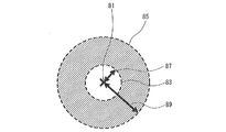
- FIG. 5 is a diagram showing an example of the display area.
- a guide display area 83 and an input display area 85 are shown.
- the guide display area 83 is an area for displaying an input guide including options and an input method for selection.
- the input display area 85 is an area for displaying a movement when performing selection according to the input guide.
- the guide display area 83 is a circle having a radius 87 with the line-of-sight position 81 as the center.
- the input display area 85 is a circle having a radius of 89 at the center of the line-of-sight position 81 and is a part other than the guide display area 83.
- the input display area 85 is in contact with the outside of the guide display area 83, and includes a point farther from the line-of-sight position 81 than the guide display area 83.
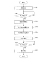
- FIG. 7 is a flowchart showing input processing in the mobile terminal device 1 according to the present embodiment.
- Each process shown in FIG. 7 is performed by, for example, the arithmetic processing device 3 reading and executing a predetermined program, but here, it is assumed that the process is executed by each function of FIG.
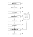
- the line-of-sight detection unit 31 starts detecting the line of sight of the user (S101).
- the line of sight may be detected by a method of detecting by image analysis or any other conventional method.
- the operation target detection unit 33 repeats the detection until a touch that triggers the start of operation target detection, such as a predetermined position of the touch panel 23, is detected (S102: NO). At this time, if no input is detected for a certain period of time, the processing may be terminated.
- the operation target detection unit 33 When a touch is detected (S102: YES), the operation target detection unit 33, for example, as shown in FIGS. 3 and 4, the line-of-sight position 55 on the line-of-sight display unit 25 when the touch is detected. And an operation target is detected based on the detected line-of-sight position 55 (S103). For example, the operation target detection unit 33 detects an image displayed at the line-of-sight position 55 as an operation target.
- the display position determination unit 37 refers to the item of the guide display area of the display position determination information 47 to determine the guide display area 83, for example, as shown in FIG.
- the display position of the input guide 57 shown in FIG. 4 is determined (S104).
- the input display area determination unit 43 refers to the item of the input display area of the display position determination information 47 and determines, for example, the input display area 85 shown in FIG. 5 and the position where the input in the input display area 85 is displayed. Determine (S105).
- the guide creation unit 35 generates an input guide corresponding to the detected operation target.
- the guide display unit 39 displays the generated input guide at the determined position (S106). At this time, for example, the guide display unit 39 arranges the center of the input guide at a predetermined position in the determined guide display area 83. In addition, the guide display unit 39 may adjust the display magnification so that the input guide fits in the guide display area 83.
- the input detection unit 41 determines whether or not an input accompanying a movement to the touch panel 23 or the like is detected (S107). For example, as described in FIGS. 3 and 4, when the input detection unit 41 detects the input 63, the input 77, etc. (S107: YES), the input display unit 45 is determined by the input display area determination unit 43, for example. The input is sequentially displayed at a predetermined position in the input display area 85 (S108), and the process returns to S107. For example, the line-of-sight detection may not be performed after the input guide 57 is displayed until the input display is completed.
- the process is repeated until a touch is detected (S107: NO).
- the input detection unit 41 may repeat the process of S107 until a predetermined time elapses, and may end the process after the predetermined time elapses. Further, by repeating the processing of S107 and S108, the input is performed while visually confirming the state of the sequential input. At this time, processing according to the input detected by the input detection unit 41 is performed.
- the line-of-sight detection unit 31 displays the line-of-sight position 55 on the line-of-sight display unit 25, for example.
- the operation target detection unit 33 detects the operation target.
- the guide creation unit 35 generates an input guide 57 corresponding to the operation target.
- the display position determination unit 37 refers to the display position determination information 47 and determines the guide display area 83.
- the input display region determination unit 43 determines, for example, the input display region 85.
- the input display unit 45 displays the movement caused by the input.
- the input display area 85 is an area other than the guide display area 83 and is determined so as to include a point farther from the line-of-sight position 55 than any point of the guide display area 83.
- the operation target can be detected from the line-of-sight position.
- the input for selecting the process for the operation target can be realized while visually confirming the movement of the finger on the touch panel 23, for example. Accordingly, it is possible to determine the operation target only when the user turns the line of sight not to always set everything that the user is looking at but to input. Therefore, the input guide is not displayed around the line-of-sight position except when necessary, and it is possible to prevent the act of viewing the display from being hindered.
- the line-of-sight position on the screen is detected from the line-of-sight information at the time of touch detection when the line-of-sight detection is started first or always and a touch as a trigger is detected. Accordingly, it is possible to estimate the line-of-sight position using past line-of-sight information, and it is possible to cope with the case where the line-of-sight cannot be detected due to a blink or the like at the time of trigger detection.
- the input guide 57 is displayed in the guide display area 83 based on the line-of-sight position 55, it is possible to refer to the input guide 57 explaining the input without moving the line of sight.
- the input display area 85 is an area other than the guide display area 83 and includes points farther from the line-of-sight position 55 than all the points in the guide display area 83.
- the input guide 57 is displayed in a field of view where, for example, color and shape can be recognized, so that while referring to the input guide 57, the movement of the finger can be confirmed at the same time without moving the line of sight. Input can be made.
- the input display indicating the input movement is displayed within a field of view where the movement can be recognized, the input movement can be visually confirmed.
- the input guide 57 does not overlap the input display 65, the input display 79, and the like, it is possible to prevent the input guide 57 from being hindered from being referred to by the input.
- the setting method of the guide display area 83 and the input display area 85 can be defined in advance by the display position determination information 47 or the like. Accordingly, it is possible to display the input guide 57, the input display 65, the input display 79, and the like according to the operation target.
- the input method according to the present embodiment has a wider field of view that can recognize movement than the field of view that can recognize characters, etc. due to the characteristics of the field of view, for example, an input method that uses the relationship between the central field of view and the peripheral field of view. can do. That is, when there is a line of sight at a certain position, there is a region in which a motion can be recognized even if a character cannot be recognized. Therefore, by separating the guide display area and the input state display area so that the input state by movement is displayed outside the area where the input guide 57 is displayed, the input guide can also be input without moving the line of sight. Progress can be recognized at the same time.
- the display of the input progress due to movement can be recognized without moving the line of sight without reducing the visibility of the input guide.
- Layout can be automatically performed.
- FIG. 8 is a diagram illustrating an input display example according to the first modification.
- a guide display area 83 and an input display area 85 are set for the line-of-sight position 81.
- the auxiliary line 91 is displayed in the input display area 85.
- the input display 93 is displayed across the auxiliary line 91.
- the input display 93 crosses the auxiliary line 91, it is determined that the input input indicates an input from the top to the bottom.
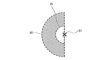
- FIGS. 9 to 11 are diagrams showing modifications of the guide display area and the input display area.
- the guide display area 95 is, for example, a semicircular area on the left side of the figure having a predetermined first radius centered on the line-of-sight position 81.
- the input display area 97 may be a semicircular area on the right side of the figure with a second radius greater than the first radius.
- the input display area 99 is a semicircular area on the left side of the drawing having a second radius larger than the first radius centered on the line-of-sight position 81 and is an area other than the guide display area 95. It can be.
- the input display area 85 is a circular area having a second radius larger than the first radius with the line-of-sight position 81 as the center, and can be an area other than the guide display area 95. .
- the input display areas 85, 97, and 99 include points farther from the line-of-sight position 81 than all the points in the guide display area 95.
- the mobile terminal device 1 displays, for example, the input guide 57 in the guide display area 95 and displays the input in any of the input display areas 85, 97, and 99, thereby fixing the line of sight at the line-of-sight position 81.
- An input method capable of confirming movement while referring to the guide 57 is realized.
- the guide display areas 59, 83, and 95 are examples of the first area
- the input display areas 61, 85, 97, and 99 are examples of the second area. It is.
- the guide 57 is an example of first information
- the input displays 65, 79, and 93 are examples of second information.
- the display position determination unit 37 is an example of a first region determination unit
- the input display region determination unit 43 is an example of a second region determination unit.
- the present invention is not limited to the embodiment described above, and various configurations or embodiments can be adopted without departing from the gist of the present invention.
- the line-of-sight detection device 21 is not limited to a device including a camera, and may be based on another device, such as detecting the line of sight by detecting the movement of facial muscles.
- Input to input other information such as information related to gaze such as gaze and blink, information related to finger movement such as tap and swipe, voice, data glove, etc.
- Means can be used.
- line-of-sight detection to start when an input serving as a trigger is performed, it is possible to reduce the power consumption by constantly starting the line-of-sight detection.
- the input method for selecting an option is not limited to the touch panel 23, and may be a method using another device capable of detecting movement, such as a data glove, for example.
- An input for selecting an option may be performed by a change over time.
- the device used at this time is a device that can detect temporal changes. For example, it is also possible to perform input based on the strength of pressing a button, for example, a change in distance in the depth direction from the terminal. At this time, it is possible to notify the input state by changing the color of the entire second region by utilizing the fact that a change in color or the like is easier to perceive in peripheral vision.
- the display position determination information 47 is an example, and other forms such as information by other parameters may be used. For example, designation by viewing angle may be used. As an example, the guide display area may be an area with a viewing angle of 2 degrees, and the input display area may be an area with a viewing angle of 5 degrees.
- the input guide 57 is displayed, and when there is no input for a certain period of time after entering the input state, the input guide is turned off, but it is determined that the user is gazing at the operation target.
- the input guide can be fixed. According to this, it becomes easy to recognize the input guide. Note that, for example, when the time during which the line of sight remains within a certain range including the operation target is longer than a predetermined time, it may be determined that the operation target is being watched.
- the operation target may be detected from the position of the cursor near the line-of-sight position. At this time, a process for regarding the cursor as a line-of-sight position is performed. As a result, the operation target can be detected with higher accuracy than the line-of-sight position.
- At least a part of the input guide may be transparently displayed. According to this, when at least a part of the input display area and the input guide 57 overlaps, it is possible to prevent recognition of the overlapped part and to recognize both at the same time.
- the input guide When the input guide is displayed, if there is no operation for a predetermined time or more, it may be determined that the user does not intend to operate and the input guide display may be deleted. Further, when the line-of-sight position is more than a certain distance from the detected operation target, it may be determined that there is no intention to operate. According to this, it becomes easy to perform the next operation and power consumption can be suppressed.
- the input method shown in the input guide is not limited to the input method by one input means. It is preferable to enable the same operation with a plurality of input means.
- the input guide 57 can have various examples. For example, if the input method is a combination of a plurality of movements such as a hierarchical menu, it can be displayed separately for each movement. As a modification of FIG. 9, by displaying the input display area 97 closer to the position where the input is detected by the touch panel 23, it is possible to make it easier to confirm the movement.
- the shapes of the guide display area and the input display area are not limited to the above, and various shapes and positional relationships can be employed.
- FIG. 12 is a block diagram illustrating an example of a hardware configuration of a standard computer.
- a computer 300 includes a central processing unit (CPU) 302, a memory 304, an input device 306, an output device 308, an external storage device 312, a medium driving device 314, a network connection device, and the like via a bus 310. It is connected.
- CPU central processing unit
- the CPU 302 is an arithmetic processing unit that controls the operation of the entire computer 300.
- the memory 304 is a storage unit for storing in advance a program for controlling the operation of the computer 300 or using it as a work area when necessary when executing the program.
- the memory 304 is, for example, a Random Access Memory (RAM), a Read Only Memory (ROM), or the like.
- the input device 306 is a device that, when input by a computer user, acquires various information input from the user associated with the input content and sends the acquired input information to the CPU 302. Keyboard device, mouse device, etc.
- the output device 308 is a device that outputs a processing result by the computer 300, and includes a display device and the like. For example, the display device displays text and images according to display data sent by the CPU 302.
- the external storage device 312 is, for example, a storage device such as a hard disk, and stores various control programs executed by the CPU 302, acquired data, and the like.
- the medium driving device 314 is a device for writing to and reading from the portable recording medium 316.
- the CPU 302 can perform various control processes by reading and executing a predetermined control program recorded on the portable recording medium 316 via the recording medium driving device 314.
- the portable recording medium 316 is, for example, a Compact Disc (CD) -ROM, a Digital Versatile Disc (DVD), a Universal Serial Bus (USB) memory, or the like.
- the network connection device 318 is an interface device that manages transmission / reception of various data performed between the outside by wired or wireless.
- a bus 310 is a communication path for connecting the above devices and the like to exchange data.
- a program that causes a computer to execute the input method according to the above embodiment and the first and second modifications is stored in, for example, the external storage device 312.
- CPU 302 reads a program from external storage device 312 and causes computer 300 to perform an input operation.
- a control program for causing the CPU 302 to perform input processing is created and stored in the external storage device 312.
- a predetermined instruction is given from the input device 306 to the CPU 302 so that the control program is read from the external storage device 312 and executed.
- the program may be stored in the portable recording medium 316.
Landscapes
- Engineering & Computer Science (AREA)
- Theoretical Computer Science (AREA)
- General Engineering & Computer Science (AREA)
- Human Computer Interaction (AREA)
- Physics & Mathematics (AREA)
- General Physics & Mathematics (AREA)
- User Interface Of Digital Computer (AREA)
- Position Input By Displaying (AREA)
Abstract
Description
以下、図8を参照しながら、入力表示の変形例を説明する。図8は、変形例1による入力表示例を示す図である。図8に示すように、視線位置81に対しガイド表示領域83、入力表示領域85が設定されている。補助線91は、入力表示領域85に表示されている。入力表示93は、補助線91を跨いで表示されている。図8の例では、例えば、入力表示93が補助線91を跨いだときに、入力された入力が上から下への入力を示していると判断するようにする。また、使用者は、補助線91を跨ぐ入力を行うように、視覚で確認することが容易になる。
以下、図9から図11を参照しながら、ガイド表示領域と入力表示領域との変形例を説明する。図9から図11は、ガイド表示領域と入力表示領域との変形例を示す図である。図9に示す例では、ガイド表示領域95を、例えば視線位置81を中心とした所定の第1の半径の図の左側の半円の領域とする。入力表示領域97は、第1の半径より大きい第2の半径の図の右側の半円の領域とすることができる。
3 演算処理装置
5 記憶部
7 ROM
9 RAM
11 通信部
13 アンテナ
15 音声入出力部
17 スピーカ
19 マイク
21 視線検出装置
23 タッチパネル
25 表示部
31 視線検出部
33 操作対象検出部
35 ガイド作成部
37 表示位置決定部
39 ガイド表示部
41 入力検出部
43 入力表示領域決定部
45 入力表示部
47 表示位置決定情報
51 表示例
53 手
55 視線位置
57 入力ガイド
59 ガイド表示領域
61 入力表示領域
Claims (10)
- 使用者の視線を検出する視線検出部と、
検出された視線の表示画面上の視線位置に基づき、前記使用者の動きによる入力方法を示す第1の情報が表示される前記表示画面上の第1の領域を決定する第1の領域決定部と、
前記第1の領域に前記第1の情報を表示する第1の表示制御部と
前記使用者による入力を検出する入力検出部と、
前記第1の領域外であって、前記第1の領域よりも前記視線位置から遠い点を含み、検出された前記入力における前記使用者の動きに応じた軌跡を示す第2の情報が表示される第2の領域を決定する第2の領域決定部と、
前記第2の領域に前記第2の情報を表示する第2の表示制御部と、
を有する情報処理装置。 - 前記第2の領域は、前記第1の領域の外側に接する領域であることを特徴とする請求項1に記載の情報処理装置。
- 前記入力検出部は、前記表示画面上における入力を検出し、
前記第2の領域は、前記入力が検出された前記表示画面上の位置と前記第1の領域との間の領域を含むことを特徴とする請求項1に記載の情報処理装置。 - 前記第2の領域には、前記入力の基準となる補助線が表示され、前記入力検出部は、前記補助線に対する相対的な動きを検出することを特徴とする請求項1から請求項3のいずれかに記載の情報処理装置。
- 前記第1の領域は、中心視が可能な領域に対応し、前記第2の領域は、周辺視が可能な領域に対応することを特徴とする請求項1から請求項4のいずれかに記載の情報処理装置。
- 使用者の視線を検出し、
検出された視線の表示画面上の視線位置に基づき、前記使用者の動きによる入力方法を示す第1の情報が表示される前記表示画面上の第1の領域を決定し、
前記第1の領域外であって、前記第1の領域よりも前記視線位置から遠い点を含み、前記使用者による入力における前記使用者の動きに応じた軌跡を示す第2の情報が表示される第2の領域を決定し、
前記第1の領域に前記第1の情報を表示し、
前記使用者による入力を検出し、
前記第2の領域に、前記第2の情報を表示する
処理をコンピュータに実行させるプログラム。 - 前記第2の領域は、前記第1の領域の外側に接する領域であることを特徴とする請求項6に記載のプログラム。
- 前記入力を検出する処理においては、前記表示画面上における入力を検出し、
前記第2の領域は、前記入力が検出された前記表示画面上の位置と前記第1の領域との間の領域を含むことを特徴とする請求項6に記載のプログラム。 - 前記第2の領域には、前記入力の基準となる補助線が表示され、前記補助線に対する相対的な動きが検出されることを特徴とする請求項6から請求項8のいずれかに記載のプログラム。
- 前記第1の領域は、中心視が可能な領域に対応し、前記第2の領域は、周辺視が可能な領域に対応することを特徴とする請求項6から請求項9のいずれかに記載のプログラム。
Priority Applications (7)
| Application Number | Priority Date | Filing Date | Title |
|---|---|---|---|
| CN201380077592.0A CN105324733A (zh) | 2013-06-25 | 2013-06-25 | 信息处理装置以及程序 |
| KR1020157035491A KR101795204B1 (ko) | 2013-06-25 | 2013-06-25 | 정보 처리 장치 및 기록 매체 |
| JP2015523705A JP6004103B2 (ja) | 2013-06-25 | 2013-06-25 | 情報処理装置およびプログラム |
| PCT/JP2013/067423 WO2014207828A1 (ja) | 2013-06-25 | 2013-06-25 | 情報処理装置およびプログラム |
| KR1020177026234A KR20170109077A (ko) | 2013-06-25 | 2013-06-25 | 정보 처리 장치 및 기록 매체 |
| EP13888066.1A EP3015963A4 (en) | 2013-06-25 | 2013-06-25 | INFORMATION PROCESSING DEVICE AND PROGRAM |
| US14/952,521 US20160077586A1 (en) | 2013-06-25 | 2015-11-25 | Information processing device that has function to detect line of sight of user |
Applications Claiming Priority (1)
| Application Number | Priority Date | Filing Date | Title |
|---|---|---|---|
| PCT/JP2013/067423 WO2014207828A1 (ja) | 2013-06-25 | 2013-06-25 | 情報処理装置およびプログラム |
Related Child Applications (1)
| Application Number | Title | Priority Date | Filing Date |
|---|---|---|---|
| US14/952,521 Continuation US20160077586A1 (en) | 2013-06-25 | 2015-11-25 | Information processing device that has function to detect line of sight of user |
Publications (1)
| Publication Number | Publication Date |
|---|---|
| WO2014207828A1 true WO2014207828A1 (ja) | 2014-12-31 |
Family
ID=52141235
Family Applications (1)
| Application Number | Title | Priority Date | Filing Date |
|---|---|---|---|
| PCT/JP2013/067423 Ceased WO2014207828A1 (ja) | 2013-06-25 | 2013-06-25 | 情報処理装置およびプログラム |
Country Status (6)
| Country | Link |
|---|---|
| US (1) | US20160077586A1 (ja) |
| EP (1) | EP3015963A4 (ja) |
| JP (1) | JP6004103B2 (ja) |
| KR (2) | KR101795204B1 (ja) |
| CN (1) | CN105324733A (ja) |
| WO (1) | WO2014207828A1 (ja) |
Cited By (6)
| Publication number | Priority date | Publication date | Assignee | Title |
|---|---|---|---|---|
| JP2016136351A (ja) * | 2015-01-23 | 2016-07-28 | 京セラ株式会社 | 電子機器及び制御方法 |
| JPWO2016121883A1 (ja) * | 2015-01-29 | 2017-08-31 | 京セラ株式会社 | 電子機器 |
| JP2019175449A (ja) * | 2018-03-28 | 2019-10-10 | 株式会社リコー | 情報処理装置、情報処理システム、移動体、情報処理方法、及びプログラム |
| JP2020149336A (ja) * | 2019-03-13 | 2020-09-17 | 株式会社リコー | 情報処理装置、表示制御方法、及びプログラム |
| JP7515732B1 (ja) * | 2023-02-15 | 2024-07-12 | 三菱電機株式会社 | 遠隔操作支援装置 |
| WO2025084378A1 (ja) * | 2023-10-19 | 2025-04-24 | パナソニックIpマネジメント株式会社 | 情報処理方法、情報処理装置、及びプログラム |
Families Citing this family (5)
| Publication number | Priority date | Publication date | Assignee | Title |
|---|---|---|---|---|
| CN106527725A (zh) * | 2016-11-16 | 2017-03-22 | 上海楼顶网络科技有限公司 | 一种vr/ar环境下的利用视野中心轨迹给设备输入信息或指令的方法 |
| WO2019189403A1 (en) * | 2018-03-28 | 2019-10-03 | Ricoh Company, Ltd. | Information processing apparatus, information processing system, information processing method, and program |
| JP7327368B2 (ja) | 2020-12-02 | 2023-08-16 | 横河電機株式会社 | 装置、方法およびプログラム |
| CN115562486A (zh) * | 2022-09-29 | 2023-01-03 | 联想(北京)有限公司 | 数据处理方法、装置、电子设备及计算机可读存储介质 |
| CN115562538A (zh) * | 2022-10-27 | 2023-01-03 | 维沃软件技术有限公司 | 应用界面显示方法及装置、电子设备和可读存储介质 |
Citations (5)
| Publication number | Priority date | Publication date | Assignee | Title |
|---|---|---|---|---|
| JP2000250677A (ja) | 1999-03-02 | 2000-09-14 | Toshiba Corp | マルチモーダルインターフェース装置及びマルチモーダルインターフェース方法 |
| WO2010143673A1 (ja) * | 2009-06-10 | 2010-12-16 | 日本電気株式会社 | 電子機器、ジェスチャー処理方法、及びジェスチャー処理プログラム |
| JP2011040008A (ja) * | 2009-08-18 | 2011-02-24 | Canon Inc | 表示制御装置及び表示制御方法、プログラム、記憶媒体 |
| WO2012147520A1 (ja) * | 2011-04-25 | 2012-11-01 | ソニー株式会社 | 表示制御装置、表示制御方法、およびプログラム |
| JP2013122529A (ja) * | 2011-12-12 | 2013-06-20 | Sharp Corp | 表示装置およびosd表示方法 |
Family Cites Families (3)
| Publication number | Priority date | Publication date | Assignee | Title |
|---|---|---|---|---|
| US7499033B2 (en) * | 2002-06-07 | 2009-03-03 | Smart Technologies Ulc | System and method for injecting ink into an application |
| WO2009018314A2 (en) * | 2007-07-30 | 2009-02-05 | Perceptive Pixel, Inc. | Graphical user interface for large-scale, multi-user, multi-touch systems |
| JP5256109B2 (ja) * | 2009-04-23 | 2013-08-07 | 株式会社日立製作所 | 表示装置 |
-
2013
- 2013-06-25 EP EP13888066.1A patent/EP3015963A4/en not_active Withdrawn
- 2013-06-25 KR KR1020157035491A patent/KR101795204B1/ko not_active Expired - Fee Related
- 2013-06-25 JP JP2015523705A patent/JP6004103B2/ja not_active Expired - Fee Related
- 2013-06-25 WO PCT/JP2013/067423 patent/WO2014207828A1/ja not_active Ceased
- 2013-06-25 KR KR1020177026234A patent/KR20170109077A/ko not_active Ceased
- 2013-06-25 CN CN201380077592.0A patent/CN105324733A/zh active Pending
-
2015
- 2015-11-25 US US14/952,521 patent/US20160077586A1/en not_active Abandoned
Patent Citations (5)
| Publication number | Priority date | Publication date | Assignee | Title |
|---|---|---|---|---|
| JP2000250677A (ja) | 1999-03-02 | 2000-09-14 | Toshiba Corp | マルチモーダルインターフェース装置及びマルチモーダルインターフェース方法 |
| WO2010143673A1 (ja) * | 2009-06-10 | 2010-12-16 | 日本電気株式会社 | 電子機器、ジェスチャー処理方法、及びジェスチャー処理プログラム |
| JP2011040008A (ja) * | 2009-08-18 | 2011-02-24 | Canon Inc | 表示制御装置及び表示制御方法、プログラム、記憶媒体 |
| WO2012147520A1 (ja) * | 2011-04-25 | 2012-11-01 | ソニー株式会社 | 表示制御装置、表示制御方法、およびプログラム |
| JP2013122529A (ja) * | 2011-12-12 | 2013-06-20 | Sharp Corp | 表示装置およびosd表示方法 |
Non-Patent Citations (1)
| Title |
|---|
| See also references of EP3015963A4 * |
Cited By (10)
| Publication number | Priority date | Publication date | Assignee | Title |
|---|---|---|---|---|
| JP2016136351A (ja) * | 2015-01-23 | 2016-07-28 | 京セラ株式会社 | 電子機器及び制御方法 |
| JPWO2016121883A1 (ja) * | 2015-01-29 | 2017-08-31 | 京セラ株式会社 | 電子機器 |
| US11112866B2 (en) | 2015-01-29 | 2021-09-07 | Kyocera Corporation | Electronic device |
| JP2019175449A (ja) * | 2018-03-28 | 2019-10-10 | 株式会社リコー | 情報処理装置、情報処理システム、移動体、情報処理方法、及びプログラム |
| JP7338184B2 (ja) | 2018-03-28 | 2023-09-05 | 株式会社リコー | 情報処理装置、情報処理システム、移動体、情報処理方法、及びプログラム |
| JP2020149336A (ja) * | 2019-03-13 | 2020-09-17 | 株式会社リコー | 情報処理装置、表示制御方法、及びプログラム |
| JP7215254B2 (ja) | 2019-03-13 | 2023-01-31 | 株式会社リコー | 情報処理装置、表示制御方法、及びプログラム |
| JP7515732B1 (ja) * | 2023-02-15 | 2024-07-12 | 三菱電機株式会社 | 遠隔操作支援装置 |
| WO2024171348A1 (ja) * | 2023-02-15 | 2024-08-22 | 三菱電機株式会社 | 遠隔操作支援装置 |
| WO2025084378A1 (ja) * | 2023-10-19 | 2025-04-24 | パナソニックIpマネジメント株式会社 | 情報処理方法、情報処理装置、及びプログラム |
Also Published As
| Publication number | Publication date |
|---|---|
| KR20170109077A (ko) | 2017-09-27 |
| KR101795204B1 (ko) | 2017-11-07 |
| JP6004103B2 (ja) | 2016-10-05 |
| KR20160010540A (ko) | 2016-01-27 |
| US20160077586A1 (en) | 2016-03-17 |
| CN105324733A (zh) | 2016-02-10 |
| EP3015963A4 (en) | 2016-07-13 |
| JPWO2014207828A1 (ja) | 2017-02-23 |
| EP3015963A1 (en) | 2016-05-04 |
Similar Documents
| Publication | Publication Date | Title |
|---|---|---|
| JP6004103B2 (ja) | 情報処理装置およびプログラム | |
| EP2996018B1 (en) | Ring-type mobile terminal | |
| CN102906671B (zh) | 手势输入装置及手势输入方法 | |
| JP6158913B2 (ja) | ジェスチャを使用したデバイスとの対話 | |
| JP6062416B2 (ja) | 情報入力装置及び情報表示方法 | |
| KR20090101733A (ko) | 휴대 단말기 및 그의 얼굴 인식을 이용한 표시정보의 표시방법 | |
| RU2677566C1 (ru) | Способ, устройство и электронное оборудование для управления виртуальной реальностью | |
| KR20140115906A (ko) | 시선 위치를 디텍트하는 디스플레이 디바이스 및 제어 방법 | |
| JP2015041052A (ja) | リストバンド型情報処理装置および記憶媒体 | |
| KR20170087292A (ko) | Hmd 디바이스 및 그 제어 방법 | |
| KR20190104758A (ko) | 이동단말기 및 그 제어 방법 | |
| JPWO2019021418A1 (ja) | 表示制御装置および表示制御方法 | |
| CN108369451B (zh) | 信息处理装置、信息处理方法及计算机可读存储介质 | |
| JP2012238086A (ja) | 画像処理装置、画像処理方法および画像処理プログラム | |
| KR20180103866A (ko) | 이동 단말기 및 그 제어 방법 | |
| KR20170058758A (ko) | Hmd 및 그 hmd의 제어 방법 | |
| KR101695695B1 (ko) | 이동단말기 및 그 제어방법 | |
| JP2014085964A (ja) | 情報処理方法、情報処理装置、及びプログラム | |
| KR20170055296A (ko) | Hmd 및 그 hmd의 제어 방법 | |
| KR20160093890A (ko) | 이동단말기 및 그 제어방법 | |
| KR101622695B1 (ko) | 이동 단말기 및 그것의 제어방법 | |
| KR20160068534A (ko) | 이동단말기 및 그 제어방법 | |
| KR20180031238A (ko) | 이동 단말기 및 그 제어방법 | |
| JPWO2018042811A1 (ja) | 情報処理装置、情報処理方法、及び記録媒体 | |
| JP2014021893A (ja) | 情報処理装置、操作信号生成方法、およびプログラム |
Legal Events
| Date | Code | Title | Description |
|---|---|---|---|
| WWE | Wipo information: entry into national phase |
Ref document number: 201380077592.0 Country of ref document: CN |
|
| 121 | Ep: the epo has been informed by wipo that ep was designated in this application |
Ref document number: 13888066 Country of ref document: EP Kind code of ref document: A1 |
|
| ENP | Entry into the national phase |
Ref document number: 2015523705 Country of ref document: JP Kind code of ref document: A |
|
| WWE | Wipo information: entry into national phase |
Ref document number: 2013888066 Country of ref document: EP |
|
| ENP | Entry into the national phase |
Ref document number: 20157035491 Country of ref document: KR Kind code of ref document: A |
|
| NENP | Non-entry into the national phase |
Ref country code: DE |