WO2014207831A1 - 内燃機関の排気再循環装置 - Google Patents
内燃機関の排気再循環装置 Download PDFInfo
- Publication number
- WO2014207831A1 WO2014207831A1 PCT/JP2013/067477 JP2013067477W WO2014207831A1 WO 2014207831 A1 WO2014207831 A1 WO 2014207831A1 JP 2013067477 W JP2013067477 W JP 2013067477W WO 2014207831 A1 WO2014207831 A1 WO 2014207831A1
- Authority
- WO
- WIPO (PCT)
- Prior art keywords
- impeller
- passage
- groove
- compressor
- internal combustion
- Prior art date
- Legal status (The legal status is an assumption and is not a legal conclusion. Google has not performed a legal analysis and makes no representation as to the accuracy of the status listed.)
- Ceased
Links
Images





Classifications
-
- F—MECHANICAL ENGINEERING; LIGHTING; HEATING; WEAPONS; BLASTING
- F02—COMBUSTION ENGINES; HOT-GAS OR COMBUSTION-PRODUCT ENGINE PLANTS
- F02M—SUPPLYING COMBUSTION ENGINES IN GENERAL WITH COMBUSTIBLE MIXTURES OR CONSTITUENTS THEREOF
- F02M26/00—Engine-pertinent apparatus for adding exhaust gases to combustion-air, main fuel or fuel-air mixture, e.g. by exhaust gas recirculation [EGR] systems
- F02M26/02—EGR systems specially adapted for supercharged engines
- F02M26/04—EGR systems specially adapted for supercharged engines with a single turbocharger
- F02M26/06—Low pressure loops, i.e. wherein recirculated exhaust gas is taken out from the exhaust downstream of the turbocharger turbine and reintroduced into the intake system upstream of the compressor
-
- F—MECHANICAL ENGINEERING; LIGHTING; HEATING; WEAPONS; BLASTING
- F02—COMBUSTION ENGINES; HOT-GAS OR COMBUSTION-PRODUCT ENGINE PLANTS
- F02B—INTERNAL-COMBUSTION PISTON ENGINES; COMBUSTION ENGINES IN GENERAL
- F02B37/00—Engines characterised by provision of pumps driven at least for part of the time by exhaust
-
- F—MECHANICAL ENGINEERING; LIGHTING; HEATING; WEAPONS; BLASTING
- F02—COMBUSTION ENGINES; HOT-GAS OR COMBUSTION-PRODUCT ENGINE PLANTS
- F02B—INTERNAL-COMBUSTION PISTON ENGINES; COMBUSTION ENGINES IN GENERAL
- F02B37/00—Engines characterised by provision of pumps driven at least for part of the time by exhaust
- F02B37/12—Control of the pumps
- F02B37/16—Control of the pumps by bypassing charging air
-
- F—MECHANICAL ENGINEERING; LIGHTING; HEATING; WEAPONS; BLASTING
- F02—COMBUSTION ENGINES; HOT-GAS OR COMBUSTION-PRODUCT ENGINE PLANTS
- F02B—INTERNAL-COMBUSTION PISTON ENGINES; COMBUSTION ENGINES IN GENERAL
- F02B39/00—Component parts, details, or accessories relating to, driven charging or scavenging pumps, not provided for in groups F02B33/00 - F02B37/00
- F02B39/16—Other safety measures for, or other control of, pumps
-
- F—MECHANICAL ENGINEERING; LIGHTING; HEATING; WEAPONS; BLASTING
- F02—COMBUSTION ENGINES; HOT-GAS OR COMBUSTION-PRODUCT ENGINE PLANTS
- F02M—SUPPLYING COMBUSTION ENGINES IN GENERAL WITH COMBUSTIBLE MIXTURES OR CONSTITUENTS THEREOF
- F02M26/00—Engine-pertinent apparatus for adding exhaust gases to combustion-air, main fuel or fuel-air mixture, e.g. by exhaust gas recirculation [EGR] systems
- F02M26/02—EGR systems specially adapted for supercharged engines
- F02M26/09—Constructional details, e.g. structural combinations of EGR systems and supercharger systems; Arrangement of the EGR and supercharger systems with respect to the engine
-
- F—MECHANICAL ENGINEERING; LIGHTING; HEATING; WEAPONS; BLASTING
- F02—COMBUSTION ENGINES; HOT-GAS OR COMBUSTION-PRODUCT ENGINE PLANTS
- F02M—SUPPLYING COMBUSTION ENGINES IN GENERAL WITH COMBUSTIBLE MIXTURES OR CONSTITUENTS THEREOF
- F02M26/00—Engine-pertinent apparatus for adding exhaust gases to combustion-air, main fuel or fuel-air mixture, e.g. by exhaust gas recirculation [EGR] systems
- F02M26/13—Arrangement or layout of EGR passages, e.g. in relation to specific engine parts or for incorporation of accessories
- F02M26/17—Arrangement or layout of EGR passages, e.g. in relation to specific engine parts or for incorporation of accessories in relation to the intake system
-
- F—MECHANICAL ENGINEERING; LIGHTING; HEATING; WEAPONS; BLASTING
- F02—COMBUSTION ENGINES; HOT-GAS OR COMBUSTION-PRODUCT ENGINE PLANTS
- F02M—SUPPLYING COMBUSTION ENGINES IN GENERAL WITH COMBUSTIBLE MIXTURES OR CONSTITUENTS THEREOF
- F02M26/00—Engine-pertinent apparatus for adding exhaust gases to combustion-air, main fuel or fuel-air mixture, e.g. by exhaust gas recirculation [EGR] systems
- F02M26/13—Arrangement or layout of EGR passages, e.g. in relation to specific engine parts or for incorporation of accessories
- F02M26/34—Arrangement or layout of EGR passages, e.g. in relation to specific engine parts or for incorporation of accessories with compressors, turbines or the like in the recirculation passage
-
- F—MECHANICAL ENGINEERING; LIGHTING; HEATING; WEAPONS; BLASTING
- F02—COMBUSTION ENGINES; HOT-GAS OR COMBUSTION-PRODUCT ENGINE PLANTS
- F02M—SUPPLYING COMBUSTION ENGINES IN GENERAL WITH COMBUSTIBLE MIXTURES OR CONSTITUENTS THEREOF
- F02M26/00—Engine-pertinent apparatus for adding exhaust gases to combustion-air, main fuel or fuel-air mixture, e.g. by exhaust gas recirculation [EGR] systems
- F02M26/13—Arrangement or layout of EGR passages, e.g. in relation to specific engine parts or for incorporation of accessories
- F02M26/35—Arrangement or layout of EGR passages, e.g. in relation to specific engine parts or for incorporation of accessories with means for cleaning or treating the recirculated gases, e.g. catalysts, condensate traps, particle filters or heaters
-
- Y—GENERAL TAGGING OF NEW TECHNOLOGICAL DEVELOPMENTS; GENERAL TAGGING OF CROSS-SECTIONAL TECHNOLOGIES SPANNING OVER SEVERAL SECTIONS OF THE IPC; TECHNICAL SUBJECTS COVERED BY FORMER USPC CROSS-REFERENCE ART COLLECTIONS [XRACs] AND DIGESTS
- Y02—TECHNOLOGIES OR APPLICATIONS FOR MITIGATION OR ADAPTATION AGAINST CLIMATE CHANGE
- Y02T—CLIMATE CHANGE MITIGATION TECHNOLOGIES RELATED TO TRANSPORTATION
- Y02T10/00—Road transport of goods or passengers
- Y02T10/10—Internal combustion engine [ICE] based vehicles
- Y02T10/12—Improving ICE efficiencies
Definitions
- the present invention relates to an exhaust gas recirculation device for an internal combustion engine. Specifically, the present invention relates to an exhaust gas recirculation (EGR) device applied to a supercharged internal combustion engine.
- EGR exhaust gas recirculation
- Patent Document 1 it is known to apply an EGR device to a supercharged internal combustion engine.
- This EGR device constitutes a low-pressure (LP) circuit EGR device.
- the LP circuit EGR device recirculates low-pressure exhaust gas to the internal combustion engine by connecting an exhaust passage downstream of the exhaust turbine and an intake passage upstream of the compressor.
- LP circuit EGR device since EGR gas can be introduced into the intake air before supercharging, a large amount of EGR gas can be recirculated to the internal combustion engine.
- the LP circuit EGR device has a problem that when the EGR gas merges with the intake air, the EGR gas is cooled and condensed water is generated. The generation of condensed water leads to the occurrence of erosion in the compressor impeller.
- the EGR device of Patent Document 1 includes an EGR heater that heats the EGR gas to a predetermined temperature in the middle of the EGR passage. If the EGR heater is operated, the temperature of the EGR gas can be raised before merging with the intake air. Therefore, it is possible to reduce the amount of condensed water upstream of the compressor and suppress the occurrence of erosion.
- the EGR heater is for heating only, and the problem of increased cost and space securing due to its installation is inevitable. Further, since the pressure loss in the EGR heater increases, the advantage of the LP circuit EGR device that can recirculate a large amount of EGR gas to the internal combustion engine may be impaired.
- an object of the present invention is to provide an exhaust gas recirculation device for an internal combustion engine that can suppress the occurrence of erosion in a compressor impeller using an existing device.
- a first invention is an exhaust gas recirculation device for an internal combustion engine, An exhaust gas recirculation passage connecting the intake passage and the exhaust passage of the internal combustion engine; A compressor that is provided downstream of a connection portion of the intake passage with the exhaust gas recirculation passage, and that stores an impeller; A storage part that is formed on an inner wall of the intake passage between the connection part and the impeller, and stores condensed water generated upstream of the compressor; A bypass passage that communicates with the reservoir and bypasses the impeller to return intake air from the downstream side to the upstream side of the impeller; It is characterized by providing.
- the second invention is the first invention, wherein The connecting portion of the bypass passage with the storage portion is provided below the rotation shaft center of the impeller.
- “Below the rotational axis center of the impeller” means a position lower than the rotational axis center of the impeller.
- the “below the impeller rotational axis center” includes not only the area directly below the impeller rotational axis center (vertically below) but also the area below the rotational axis center and outside the area. included.
- the third invention is the first or second invention, wherein The storage part is formed inside the compressor.
- the storage portion is an annular groove formed so as to surround the intake passage.
- the condensed water can be stored in the reservoir.
- the reservoir is formed on the inner wall of the intake passage between the connection portion of the intake passage to the exhaust gas recirculation passage and the impeller, and bypasses the impeller and returns the intake air from the downstream side to the upstream side of the impeller Communicated with. Therefore, the condensed water accumulated in the storage portion can be discharged and blown off to the central portion of the intake passage by the intake air returned from the downstream side to the upstream side of the impeller, and can be brought into contact with the central portion of the front end surface of the impeller.
- the central portion On the front end face of the impeller, the central portion has a lower peripheral speed than the outer peripheral portion, and therefore erosion due to contact of condensed water hardly occurs in the central portion.
- the bypass passage is generally provided in a supercharged internal combustion engine. Therefore, according to the first aspect, it is possible to suppress the occurrence of erosion in the compressor impeller using the existing device.
- the connecting portion with the storage portion of the bypass passage is provided below the center of the impeller's rotation shaft, the condensed water discharged from the storage portion can be blown off to the central portion of the intake passage.
- the condensed water can be stored immediately upstream of the impeller. Moreover, since the movement distance until the impeller reaches the impeller which is discharged from the storage portion can be shortened, the contact energy when the condensate comes into contact with the impeller can be reduced. Therefore, the occurrence of erosion in the compressor impeller can be further suppressed.
- the condensed water generated upstream of the compressor can be stored in the annular groove formed so as to surround the intake passage.
- FIG. 4 is a flowchart showing a processing routine of erosion countermeasure ABV operation control executed by an ECU 50 in the embodiment. It is a figure for demonstrating the modification of embodiment. It is a figure for demonstrating the modification of embodiment. It is a figure for demonstrating the modification of embodiment.
- FIG. 1 is a diagram for explaining the configuration of the LP circuit EGR device according to the present embodiment.
- the LP circuit EGR device includes an engine 10 as an internal combustion engine mounted on a vehicle or the like.
- Each cylinder of the engine 10 is provided with a piston, an intake valve, an exhaust valve, a fuel injector, and the like.
- the engine 10 is shown as an in-line four-cylinder engine, but the number of cylinders and the cylinder arrangement of the engine 10 are not limited to this.
- the LP circuit EGR device includes a supercharger 12.
- the supercharger 12 includes a turbine 16 provided in the exhaust passage 14 and a compressor 20 provided in the intake passage 18.
- the turbine 16 and the compressor 20 are connected to each other.
- the turbine 16 receives the exhaust pressure and rotates, thereby driving the compressor 20 and compressing the gas flowing into the compressor 20.
- the intake passage 18 is provided with an intercooler 22 for cooling the compressed gas.
- a throttle valve 24 is provided downstream of the intercooler 22.
- the LP circuit EGR device includes an EGR passage 26 for introducing the exhaust gas flowing through the exhaust passage 14 into the intake passage 18.
- the EGR passage 26 connects the exhaust passage 14 downstream of the exhaust treatment device 28 and the intake passage 18 upstream of the compressor 20.
- an EGR cooler 30 that cools the exhaust gas (that is, EGR gas) flowing through the EGR passage 26 is provided.
- An EGR valve 32 that controls the flow rate of EGR gas introduced into the intake passage 18 is attached to the EGR cooler 30.
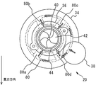
- FIG. 2 is a schematic diagram as viewed in the direction of arrow A in FIG.
- the compressor 20 includes a housing 34 that forms an outer shell of the compressor 20 and has a substantially circular front surface, a flange 36 that is provided at the center of the housing 34, and an outer peripheral portion of the housing 34. And an air bypass valve (ABV) 38.
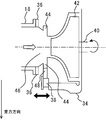
- An impeller 42 that is rotatably installed around the shaft 40 is accommodated in the housing 34.
- the ABV 38 is a normally closed electromagnetic valve and is provided below the direction of gravity (vertical direction).
- FIG. 3 is a schematic view taken along arrow BB in FIG.
- the groove 44 is formed in the outer peripheral portion of the inlet 46 that guides the gas to the suction side of the impeller 42.
- a part of the groove 44 communicates with the air outlet portion of the air bypass passage 48 partially closed by the ABV 38.
- An air inlet portion of the air bypass passage 48 communicates with a scroll (not shown) of the housing 34. That is, the air bypass passage is formed inside the housing 34.
- the LP circuit EGR device includes an ECU (Electronic Control Unit) 50 as a control device.
- ECU 50 Electronic Control Unit
- various sensors necessary for controlling the engine 10 for example, a temperature sensor for detecting the engine coolant temperature, a crank angle sensor for detecting the engine speed, etc. are electrically connected. Yes.
- various actuators are electrically connected to the output side of the ECU 50.
- the ECU 50 executes a predetermined program based on input information from the various sensors described above, and operates the various actuators described above, thereby performing various erosion countermeasure ABV operation control described below and various operations related to the operation of the engine 10. Execute the control.
- FIG. 4 is a diagram for explaining a problem in the conventional LP circuit EGR device.
- condensed water may be generated in the intake passage 62 upstream of the impeller 60. This is because water vapor in the EGR gas is cooled by the inner wall of the intake passage 62 or fresh air, and this condensed water is particularly likely to occur when the outside air temperature is low.
- the condensed water generated by the contact with the fresh air flows through the central portions of the intake passage 62 and the inlet 64 and flows into the impeller 60 from the central portion of the impeller 60 (that is, near the shaft 66).
- the condensed water produced by the contact with the inner wall of the intake passage 62 and the condensed water produced by the contact with the fresh air and adhering to the inner wall move along the inner wall.
- the condensed water that moves along the inner wall moves to the inner wall of the inlet 64 while increasing its size, and contacts the outer peripheral portion 60 a of the front end surface of the impeller 60. If it does so, erosion will generate
- the condensed water moving on the inner wall of the intake passage 18 can be collected in the groove 44. Therefore, damage to the outer peripheral portion of the front end surface of the impeller 42 due to contact with condensed water can be prevented.
- the capacity of the groove 44 is limited, there is a possibility that the condensed water overflows from the groove 44. If the condensed water is accumulated in the groove 44 for a long time, there is a possibility that corrosion around the groove 44 may be caused. Therefore, in the present embodiment, control is performed to operate the ABV 38 and discharge the condensed water from the groove 44 while collecting the condensed water in the groove 44 (erosion countermeasure ABV operation control).
- the erosion countermeasure ABV operation control is control for opening the ABV 38 when the operation condition of the ABV 38 and the condensed water generation condition are satisfied.
- the above operating condition is a normal operating condition of the ABV 38, and is established when the throttle valve 24 is suddenly closed during high supercharging.
- the reason for opening the ABV 38 when the above operating condition is satisfied is that if the throttle valve 24 is suddenly closed during high supercharging, the pressure downstream of the impeller 42 increases and the turbo rotation decreases, and the engine torque does not come out at the next acceleration and the driver of the vehicle or the like. This is because it cannot drive as intended.
- the condensed water generation condition is a characteristic condition of the present embodiment, and is established when condensed water is generated or adheres to the inner wall of the intake passage 18 upstream of the impeller 42. By opening the ABV 38 when the condensed water generation condition is satisfied, the condensed water collected in the groove 44 can be discharged by communicating the scroll and the groove 44.
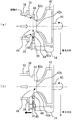
- FIG. 5 is a diagram for explaining erosion countermeasure ABV operation control.
- condensed water may be generated on the inner wall of the intake passage 18 upstream of the impeller 42.
- the generated condensed water can flow into the groove 44 and be temporarily stored (FIG. 5A).
- the condensed water that has flowed into the groove 44 moves in the groove 44 downward in the direction of gravity (that is, on the ABV 38 side) (FIG. 5A).
- the condensed water accumulated in the groove 44 on the ABV 38 side is discharged (FIG. 5B).
- the condensed water accumulated in the groove 44 on the ABV 38 side is put on the return gas flow from the downstream side to the upstream side of the impeller 42 and blown off to the central portion of the inlet 46, and the center of the front end face of the impeller 42 along with the intake air flowing through the central portion. It flows into the compressor 20 from the portion 42b (that is, near the shaft 40) (FIG. 5B).
- the central portion 42b has a lower peripheral speed than the outer peripheral portion 42a, and therefore erosion due to the contact of condensed water is less likely to occur than the outer peripheral portion 42a. That is, the occurrence of erosion in the impeller 42 can be suppressed.
- FIG. 6 is a flowchart showing a processing routine for erosion countermeasure ABV operation control executed by the ECU 50 in the present embodiment. Note that the routine shown in FIG. 6 is repeatedly executed when the supercharging pressure becomes equal to or higher than the set value.
- the ECU 50 obtains the temperature and flow rate of the EGR gas and the temperature and flow rate of the intake air (step 100).
- the temperature of the EGR gas is calculated using a model or the like stored separately in the ECU 50.
- the flow rate of the EGR gas is calculated from a signal from the EGR opening degree sensor 56.
- the intake air temperature and flow rate are calculated from signals from the air flow meter 52.
- the ECU 50 determines success or failure of the condensate generation condition using the value acquired in step 100 (step 110). Specifically, the ECU 50 first calculates the inner wall temperature of the intake passage 18 upstream of the impeller 42 using the value acquired in step 100, and calculates the dew point temperature of the mixed gas of EGR gas and intake air. When the inner wall temperature is lower than the dew point temperature, it can be determined that condensed water is generated on or adhered to the inner wall, so the ECU 50 proceeds to step 120. On the other hand, when the inner wall temperature is equal to or higher than the dew point temperature, it can be determined that the condensate generation condition is not satisfied, and thus the ECU 50 ends this routine.
- step 120 the ECU 50 determines whether or not the above operating conditions are met. Specifically, the ECU 50 determines the success or failure of the above operating condition from the signal of the throttle opening sensor 54 using the gradient of the throttle opening. If the absolute value of the gradient exceeds a predetermined reference value, it can be determined that the throttle valve 24 has been suddenly closed, so the ECU 50 proceeds to step 130 and activates the ABV 38. On the other hand, when the absolute value of the gradient is equal to or less than the predetermined reference value, it can be determined that the operating condition is not satisfied, and thus the ECU 50 ends this routine.
- the ABV 38 is operated. Can do. Therefore, the condensed water collected in the groove 44 on the ABV 38 side can be discharged by the return gas and brought into contact with the central portion 42b and then flowed into the impeller 42. Therefore, the occurrence of erosion at the outer peripheral portion 42a of the impeller 42 can be suppressed.
- the EGR passage 26 is the “exhaust recirculation passage” of the first invention
- the compressor 20 is the “compressor” of the invention
- the groove 44 is the “reservoir” of the invention.
- the air bypass passage 48 corresponds to the “bypass passage” of the present invention.
- the air outlet portion of the air bypass passage 48 corresponds to the “connecting portion” of the second invention.
- the groove 44 is formed in a direction perpendicular to the flow direction of the intake air.
- the formation direction of the groove 44 is not limited to this, and various modifications can be made.
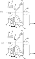
- FIG. 7 is a diagram for explaining a modification of the present embodiment.
- the groove 70 may be formed in a direction parallel to the flow direction of the intake air (FIG. 7A). Or you may form the groove
- FIG. 8 is a diagram for explaining a modification of the present embodiment.
- the diameter of the inlet 76 is substantially constant from the intake passage 18 side to the inner wall 78, and is smaller on the downstream side than the inner wall 78.
- the inner wall 78 forms a plane parallel to the front end surface of the impeller 42 and is formed so as to surround the outer peripheral portion of the front end surface. Therefore, as shown in FIG. 8, the condensed water moving on the inner wall of the intake passage 18 is blocked by the inner wall 78 and temporarily stored in the lower part in the direction of gravity (that is, on the air bypass passage 48 side). Therefore, if such a dam portion is formed in the housing, it is possible to obtain the same effect as the above-described embodiment.
- FIG. 9 is a diagram for explaining a modification of the present embodiment. As shown in FIG. 9, even if the air outlet portion 80 having a plurality of return portions 80a to 80d is provided on the outer periphery of the groove 44, the condensed water accumulated in the groove 44 is discharged by the return gas, and the central portion of the impeller 42 is discharged. Can flow into the impeller 42. Therefore, it is possible to obtain the same effect as this embodiment.
- the air bypass passage 48 and the groove 44 are formed inside the housing 34, but may be formed outside the housing 34. That is, these may be formed on the inner wall of the intake passage 18 between the gas outlet portion of the EGR passage 26 and the impeller 42.
Landscapes
- Engineering & Computer Science (AREA)
- Chemical & Material Sciences (AREA)
- Combustion & Propulsion (AREA)
- Mechanical Engineering (AREA)
- General Engineering & Computer Science (AREA)
- Chemical Kinetics & Catalysis (AREA)
- Exhaust-Gas Circulating Devices (AREA)
- Supercharger (AREA)
Abstract
Description
内燃機関の吸気通路と排気通路とを接続する排気再循環通路と、
前記吸気通路の前記排気再循環通路との接続部よりも下流に設けられ、インペラを収容するコンプレッサと、
前記接続部と前記インペラの間の前記吸気通路の内壁に形成され、前記コンプレッサの上流で発生した凝縮水を貯留する貯留部と、
前記貯留部と連通し、且つ、前記インペラをバイパスして前記インペラの下流から上流に吸気を戻すバイパス通路と、
を備えることを特徴とする。
前記バイパス通路の前記貯留部との接続部が、前記インペラの回転軸中心よりも下方に設けられることを特徴とする。「インペラの回転軸中心よりも下方」とは、インペラの回転軸中心よりも低い位置を意味している。「インペラの回転軸中心よりも下方」には、インペラの回転軸中心の直下(鉛直下方)の領域のみならず、該回転軸中心よりも下側であって該領域よりも外側の領域もが含まれる。
前記貯留部が前記コンプレッサの内部に形成されていることを特徴とする。
前記貯留部が、前記吸気通路を取り囲むように形成された環状の溝であることを特徴とする。
図1は、本実施の形態のLP回路EGR装置の構成を説明するための図である。図1に示すように、LP回路EGR装置は、車両等に搭載される内燃機関としてのエンジン10を備えている。エンジン10の各気筒には、ピストン、吸気弁、排気弁、燃料インジェクタ等が設けられている。なお、図1においては、エンジン10を直列4気筒エンジンとして示すが、エンジン10の気筒数および気筒配置はこれに限定されない。
図4は、従来のLP回路EGR装置における問題を説明するための図である。図4に示すように、従来の装置においては、インペラ60上流の吸気通路62内で凝縮水が生じることがある。この理由は、EGRガス中の水蒸気が吸気通路62の内壁または新気によって冷やされるためであり、外気温が低い場合にこの凝縮水が特に生じ易い。新気との接触によって生じた凝縮水は、吸気通路62およびインレット64の中心部を流れてインペラ60の中央部(つまり、シャフト66近傍)からインペラ60内に流入する。一方、吸気通路62の内壁との接触によって生じた凝縮水や、新気との接触によって生じ当該内壁に付着した凝縮水は、当該内壁に沿って移動する。当該内壁に沿って移動する凝縮水は、そのサイズを拡大しつつインレット64の内壁へと移動し、インペラ60の前端面の外周部60aに接触する。そうすると、外周部60aにおいてエロージョンが発生し、その結果、過給効率が低下するという問題がある。
エロージョン対策ABV作動制御とは、ABV38の作動条件かつ凝縮水発生条件が成立した場合に、ABV38を開く制御である。上記作動条件は、ABV38の通常の作動条件であり、高過給時にスロットルバルブ24を急激に閉じた際に成立する。上記作動条件の成立時にABV38を開く理由は、高過給時にスロットルバルブ24を急激に閉じるとインペラ42下流の圧力が高まりターボ回転が低下し、次回加速時にエンジントルクが出ず車両等の運転者の意図どおりの運転ができないためである。また、上記凝縮水発生条件は、本実施の形態の特徴的な条件であり、インペラ42上流の吸気通路18の内壁に凝縮水が発生し、または付着する際に成立する。上記凝縮水発生条件の成立時にABV38を開くことで、スクロールと溝44とを連通して溝44に収集した凝縮水を排出できる。
図6は、本実施の形態において、ECU50により実行されるエロージョン対策ABV作動制御の処理ルーチンを示すフローチャートである。なお、図6に示すルーチンは、過給圧が設定値以上となった場合に繰り返して実行されるものとする。
また、エアバイパス通路48のエア出口部が上記第2の発明の「接続部」に相当している。
12 過給機
14 排気通路
18,62 吸気通路
20 コンプレッサ
24 スロットルバルブ
26 EGR通路
34,74 ハウジング
38 エアバイパスバルブ(ABV)
42,60 インペラ
44,70,72 溝
46,64,76 インレット
48 エアバイパス通路
50 ECU
Claims (4)
- 内燃機関の吸気通路と排気通路とを接続する排気再循環通路と、
前記吸気通路の前記排気再循環通路との接続部よりも下流に設けられ、インペラを収容するコンプレッサと、
前記接続部と前記インペラの間の前記吸気通路の内壁に形成され、前記コンプレッサの上流で発生した凝縮水を貯留する貯留部と、
前記貯留部と連通し、且つ、前記インペラをバイパスして前記インペラの下流から上流に吸気を戻すバイパス通路と、
を備えることを特徴とする内燃機関の排気再循環装置。 - 前記バイパス通路の前記貯留部との接続部が、前記インペラの回転軸中心よりも下方に設けられることを特徴とする請求項1に記載の内燃機関の排気再循環装置。
- 前記貯留部が前記コンプレッサの内部に形成されていることを特徴とする請求項1または2に記載の内燃機関の排気再循環装置。
- 前記貯留部が、前記吸気通路を取り囲むように形成された環状の溝であることを特徴とする請求項1乃至3何れか1項に記載の内燃機関の排気再循環装置。
Priority Applications (5)
| Application Number | Priority Date | Filing Date | Title |
|---|---|---|---|
| PCT/JP2013/067477 WO2014207831A1 (ja) | 2013-06-26 | 2013-06-26 | 内燃機関の排気再循環装置 |
| US14/392,136 US10006414B2 (en) | 2013-06-26 | 2013-06-26 | Condensate storage and removal in low pressure exhaust gas recirculation system |
| EP13888195.8A EP3015675B1 (en) | 2013-06-26 | 2013-06-26 | Exhaust recirculation device for internal combustion engine |
| CN201380077777.1A CN105339624B (zh) | 2013-06-26 | 2013-06-26 | 内燃机的排气再循环装置 |
| JP2014521382A JP5825434B2 (ja) | 2013-06-26 | 2013-06-26 | 内燃機関の排気再循環装置 |
Applications Claiming Priority (1)
| Application Number | Priority Date | Filing Date | Title |
|---|---|---|---|
| PCT/JP2013/067477 WO2014207831A1 (ja) | 2013-06-26 | 2013-06-26 | 内燃機関の排気再循環装置 |
Publications (1)
| Publication Number | Publication Date |
|---|---|
| WO2014207831A1 true WO2014207831A1 (ja) | 2014-12-31 |
Family
ID=52141238
Family Applications (1)
| Application Number | Title | Priority Date | Filing Date |
|---|---|---|---|
| PCT/JP2013/067477 Ceased WO2014207831A1 (ja) | 2013-06-26 | 2013-06-26 | 内燃機関の排気再循環装置 |
Country Status (5)
| Country | Link |
|---|---|
| US (1) | US10006414B2 (ja) |
| EP (1) | EP3015675B1 (ja) |
| JP (1) | JP5825434B2 (ja) |
| CN (1) | CN105339624B (ja) |
| WO (1) | WO2014207831A1 (ja) |
Cited By (1)
| Publication number | Priority date | Publication date | Assignee | Title |
|---|---|---|---|---|
| US10145296B2 (en) | 2015-12-11 | 2018-12-04 | Man Truck & Bus Ag | Exhaust-gas turbocharger for a motor vehicle |
Families Citing this family (9)
| Publication number | Priority date | Publication date | Assignee | Title |
|---|---|---|---|---|
| US10323607B2 (en) * | 2016-07-14 | 2019-06-18 | Ge Global Sourcing Llc | Method and systems for draining fluid from an engine |
| CN106499549B (zh) * | 2016-11-30 | 2018-09-11 | 安徽江淮汽车集团股份有限公司 | 一种egr导流管结构 |
| DE102017210648A1 (de) * | 2017-06-23 | 2018-12-27 | Ford Global Technologies, Llc | Kondensatfalle in einem Verdichter-Einlass |
| GB2565292B (en) * | 2017-08-07 | 2019-08-21 | Ford Global Tech Llc | A condensate management device for a turbocharged engine |
| JP6455581B1 (ja) * | 2017-11-17 | 2019-01-23 | マツダ株式会社 | エンジンの制御装置及びエンジンの制御方法 |
| CN110374765A (zh) * | 2018-04-12 | 2019-10-25 | 罗伯特·博世有限公司 | 具有天然气燃料的废气循环系统及其发动机 |
| DE102018111560B4 (de) * | 2018-05-15 | 2025-12-31 | Volkswagen Aktiengesellschaft | Verdichter mit Trimmsteller und Drainageleitung und Brennkraftmaschine mit einem solchen Verdichter |
| US20200025157A1 (en) * | 2018-07-17 | 2020-01-23 | GM Global Technology Operations LLC | Exhaust gas recirculation system and method of operating the same |
| ES2875173B2 (es) * | 2021-03-11 | 2023-06-15 | Univ Valencia Politecnica | Dispositivo y procedimiento de emulacion de sistemas de sobrealimentacion |
Citations (6)
| Publication number | Priority date | Publication date | Assignee | Title |
|---|---|---|---|---|
| JP2009524775A (ja) * | 2006-01-27 | 2009-07-02 | ボーグワーナー・インコーポレーテッド | 低圧egr凝縮液をコンプレッサにおいて/コンプレッサの前に再導入するユニット |
| JP2009174444A (ja) | 2008-01-25 | 2009-08-06 | Honda Motor Co Ltd | Egr装置 |
| JP2009270524A (ja) * | 2008-05-09 | 2009-11-19 | Toyota Motor Corp | 過給機付き内燃機関 |
| JP2010525231A (ja) * | 2007-04-24 | 2010-07-22 | マン ウント フンメル ゲゼルシャフト ミット ベシュレンクテル ハフツング | 排ガスターボチャージャを具えた内燃機関 |
| JP2012057634A (ja) * | 2007-06-21 | 2012-03-22 | Toyota Motor Corp | 内燃機関の排気還流装置 |
| JP2012149588A (ja) * | 2011-01-20 | 2012-08-09 | Denso Corp | 内燃機関の制御装置 |
Family Cites Families (8)
| Publication number | Priority date | Publication date | Assignee | Title |
|---|---|---|---|---|
| KR20080095843A (ko) * | 2006-01-27 | 2008-10-29 | 보그워너 인코포레이티드 | 압축기로 들어가는 저압 egr 응축물의 혼합 유닛 |
| US20090241515A1 (en) * | 2008-03-26 | 2009-10-01 | Denso International America, Inc. | Exhaust condensation separator |
| JP2009264339A (ja) | 2008-04-28 | 2009-11-12 | Toyota Motor Corp | 内燃機関の排気還流装置 |
| JP5708507B2 (ja) * | 2012-01-18 | 2015-04-30 | トヨタ自動車株式会社 | 内燃機関のコンプレッサデポジット洗浄装置 |
| WO2014170954A1 (ja) * | 2013-04-16 | 2014-10-23 | トヨタ自動車株式会社 | 排気ターボ過給機のコンプレッサ |
| JP2014231821A (ja) * | 2013-05-30 | 2014-12-11 | トヨタ自動車株式会社 | 過給機付き内燃機関の制御装置 |
| JP6206163B2 (ja) * | 2013-12-20 | 2017-10-04 | トヨタ自動車株式会社 | 内燃機関の制御システム |
| JP6070587B2 (ja) * | 2014-01-22 | 2017-02-01 | トヨタ自動車株式会社 | 内燃機関 |
-
2013
- 2013-06-26 WO PCT/JP2013/067477 patent/WO2014207831A1/ja not_active Ceased
- 2013-06-26 EP EP13888195.8A patent/EP3015675B1/en not_active Not-in-force
- 2013-06-26 JP JP2014521382A patent/JP5825434B2/ja not_active Expired - Fee Related
- 2013-06-26 US US14/392,136 patent/US10006414B2/en active Active
- 2013-06-26 CN CN201380077777.1A patent/CN105339624B/zh not_active Expired - Fee Related
Patent Citations (6)
| Publication number | Priority date | Publication date | Assignee | Title |
|---|---|---|---|---|
| JP2009524775A (ja) * | 2006-01-27 | 2009-07-02 | ボーグワーナー・インコーポレーテッド | 低圧egr凝縮液をコンプレッサにおいて/コンプレッサの前に再導入するユニット |
| JP2010525231A (ja) * | 2007-04-24 | 2010-07-22 | マン ウント フンメル ゲゼルシャフト ミット ベシュレンクテル ハフツング | 排ガスターボチャージャを具えた内燃機関 |
| JP2012057634A (ja) * | 2007-06-21 | 2012-03-22 | Toyota Motor Corp | 内燃機関の排気還流装置 |
| JP2009174444A (ja) | 2008-01-25 | 2009-08-06 | Honda Motor Co Ltd | Egr装置 |
| JP2009270524A (ja) * | 2008-05-09 | 2009-11-19 | Toyota Motor Corp | 過給機付き内燃機関 |
| JP2012149588A (ja) * | 2011-01-20 | 2012-08-09 | Denso Corp | 内燃機関の制御装置 |
Cited By (1)
| Publication number | Priority date | Publication date | Assignee | Title |
|---|---|---|---|---|
| US10145296B2 (en) | 2015-12-11 | 2018-12-04 | Man Truck & Bus Ag | Exhaust-gas turbocharger for a motor vehicle |
Also Published As
| Publication number | Publication date |
|---|---|
| EP3015675A4 (en) | 2016-08-03 |
| CN105339624A (zh) | 2016-02-17 |
| EP3015675A1 (en) | 2016-05-04 |
| US10006414B2 (en) | 2018-06-26 |
| JP5825434B2 (ja) | 2015-12-02 |
| CN105339624B (zh) | 2018-06-05 |
| JPWO2014207831A1 (ja) | 2017-02-23 |
| EP3015675B1 (en) | 2017-10-04 |
| US20160186701A1 (en) | 2016-06-30 |
Similar Documents
| Publication | Publication Date | Title |
|---|---|---|
| JP5825434B2 (ja) | 内燃機関の排気再循環装置 | |
| JP5527486B2 (ja) | 内燃機関の換気制御装置 | |
| JP5673896B2 (ja) | 内燃機関の制御装置 | |
| CN204267177U (zh) | 涡轮增压器的压缩机 | |
| CN105324558B (zh) | 具有进气旁路装置的发动机系统 | |
| US9765712B2 (en) | System and method for turbocharger compressor surge control | |
| US8820071B2 (en) | Integrated compressor housing and inlet | |
| JP2016006310A (ja) | 内燃機関の制御システム | |
| JP6339701B2 (ja) | 内燃機関の冷却制御装置 | |
| CN203939586U (zh) | 带有具有集成的排出通道的汽缸盖的内燃发动机 | |
| US20110283977A1 (en) | Control apparatus for internal combustion engine with supercharger | |
| JP7012611B2 (ja) | 過給システム | |
| US20060042588A1 (en) | Swirl generator for a radial compressor | |
| WO2015098391A1 (en) | Exhaust gas recirculation apparatus for internal combustion engine with supercharger | |
| JP2009270524A (ja) | 過給機付き内燃機関 | |
| JP7273138B2 (ja) | サージング抑制装置、排気タービン式の過給機およびサージング抑制方法 | |
| JP5682245B2 (ja) | 低圧ループegr装置 | |
| JP6642321B2 (ja) | エンジン | |
| JP7413734B2 (ja) | ガス流量算出方法 | |
| JP6565816B2 (ja) | 過給機の制御装置 | |
| JP2007303380A (ja) | 内燃機関の排気制御装置 | |
| JP2015086722A (ja) | 内燃機関 | |
| JP5577836B2 (ja) | 内燃機関のブローバイガス処理装置 | |
| JP2009209816A (ja) | 内燃機関の制御装置 | |
| JP2016205254A (ja) | 内燃機関用過給システム |
Legal Events
| Date | Code | Title | Description |
|---|---|---|---|
| WWE | Wipo information: entry into national phase |
Ref document number: 201380077777.1 Country of ref document: CN |
|
| ENP | Entry into the national phase |
Ref document number: 2014521382 Country of ref document: JP Kind code of ref document: A |
|
| 121 | Ep: the epo has been informed by wipo that ep was designated in this application |
Ref document number: 13888195 Country of ref document: EP Kind code of ref document: A1 |
|
| REEP | Request for entry into the european phase |
Ref document number: 2013888195 Country of ref document: EP |
|
| WWE | Wipo information: entry into national phase |
Ref document number: 14392136 Country of ref document: US Ref document number: 2013888195 Country of ref document: EP |
|
| NENP | Non-entry into the national phase |
Ref country code: DE |