WO2014208226A1 - 糊付け不良検知システム及び糊付け不良検知方法 - Google Patents
糊付け不良検知システム及び糊付け不良検知方法 Download PDFInfo
- Publication number
- WO2014208226A1 WO2014208226A1 PCT/JP2014/063628 JP2014063628W WO2014208226A1 WO 2014208226 A1 WO2014208226 A1 WO 2014208226A1 JP 2014063628 W JP2014063628 W JP 2014063628W WO 2014208226 A1 WO2014208226 A1 WO 2014208226A1
- Authority
- WO
- WIPO (PCT)
- Prior art keywords
- gluing
- light
- gypsum board
- light receiving
- failure
- Prior art date
- Legal status (The legal status is an assumption and is not a legal conclusion. Google has not performed a legal analysis and makes no representation as to the accuracy of the status listed.)
- Ceased
Links
Images


Classifications
-
- G—PHYSICS
- G01—MEASURING; TESTING
- G01N—INVESTIGATING OR ANALYSING MATERIALS BY DETERMINING THEIR CHEMICAL OR PHYSICAL PROPERTIES
- G01N21/00—Investigating or analysing materials by the use of optical means, i.e. using sub-millimetre waves, infrared, visible or ultraviolet light
- G01N21/84—Systems specially adapted for particular applications
- G01N21/88—Investigating the presence of flaws or contamination
- G01N21/89—Investigating the presence of flaws or contamination in moving material, e.g. running paper or textiles
-
- B—PERFORMING OPERATIONS; TRANSPORTING
- B32—LAYERED PRODUCTS
- B32B—LAYERED PRODUCTS, i.e. PRODUCTS BUILT-UP OF STRATA OF FLAT OR NON-FLAT, e.g. CELLULAR OR HONEYCOMB, FORM
- B32B13/00—Layered products comprising a a layer of water-setting substance, e.g. concrete, plaster, asbestos cement, or like builders' material
- B32B13/04—Layered products comprising a a layer of water-setting substance, e.g. concrete, plaster, asbestos cement, or like builders' material comprising such water setting substance as the main or only constituent of a layer, which is next to another layer of the same or of a different material
- B32B13/08—Layered products comprising a a layer of water-setting substance, e.g. concrete, plaster, asbestos cement, or like builders' material comprising such water setting substance as the main or only constituent of a layer, which is next to another layer of the same or of a different material of paper or cardboard
-
- B—PERFORMING OPERATIONS; TRANSPORTING
- B32—LAYERED PRODUCTS
- B32B—LAYERED PRODUCTS, i.e. PRODUCTS BUILT-UP OF STRATA OF FLAT OR NON-FLAT, e.g. CELLULAR OR HONEYCOMB, FORM
- B32B29/00—Layered products comprising a layer of paper or cardboard
- B32B29/002—Layered products comprising a layer of paper or cardboard as the main or only constituent of a layer, which is next to another layer of the same or of a different material
- B32B29/005—Layered products comprising a layer of paper or cardboard as the main or only constituent of a layer, which is next to another layer of the same or of a different material next to another layer of paper or cardboard layer
-
- B—PERFORMING OPERATIONS; TRANSPORTING
- B32—LAYERED PRODUCTS
- B32B—LAYERED PRODUCTS, i.e. PRODUCTS BUILT-UP OF STRATA OF FLAT OR NON-FLAT, e.g. CELLULAR OR HONEYCOMB, FORM
- B32B3/00—Layered products comprising a layer with external or internal discontinuities or unevennesses, or a layer of non-planar shape; Layered products comprising a layer having particular features of form
- B32B3/02—Layered products comprising a layer with external or internal discontinuities or unevennesses, or a layer of non-planar shape; Layered products comprising a layer having particular features of form characterised by features of form at particular places, e.g. in edge regions
- B32B3/04—Layered products comprising a layer with external or internal discontinuities or unevennesses, or a layer of non-planar shape; Layered products comprising a layer having particular features of form characterised by features of form at particular places, e.g. in edge regions characterised by at least one layer folded at the edge, e.g. over another layer ; characterised by at least one layer enveloping or enclosing a material
-
- B—PERFORMING OPERATIONS; TRANSPORTING
- B32—LAYERED PRODUCTS
- B32B—LAYERED PRODUCTS, i.e. PRODUCTS BUILT-UP OF STRATA OF FLAT OR NON-FLAT, e.g. CELLULAR OR HONEYCOMB, FORM
- B32B7/00—Layered products characterised by the relation between layers; Layered products characterised by the relative orientation of features between layers, or by the relative values of a measurable parameter between layers, i.e. products comprising layers having different physical, chemical or physicochemical properties; Layered products characterised by the interconnection of layers
- B32B7/04—Interconnection of layers
- B32B7/05—Interconnection of layers the layers not being connected over the whole surface, e.g. discontinuous connection or patterned connection
-
- B—PERFORMING OPERATIONS; TRANSPORTING
- B32—LAYERED PRODUCTS
- B32B—LAYERED PRODUCTS, i.e. PRODUCTS BUILT-UP OF STRATA OF FLAT OR NON-FLAT, e.g. CELLULAR OR HONEYCOMB, FORM
- B32B7/00—Layered products characterised by the relation between layers; Layered products characterised by the relative orientation of features between layers, or by the relative values of a measurable parameter between layers, i.e. products comprising layers having different physical, chemical or physicochemical properties; Layered products characterised by the interconnection of layers
- B32B7/04—Interconnection of layers
- B32B7/12—Interconnection of layers using interposed adhesives or interposed materials with bonding properties
-
- G—PHYSICS
- G01—MEASURING; TESTING
- G01N—INVESTIGATING OR ANALYSING MATERIALS BY DETERMINING THEIR CHEMICAL OR PHYSICAL PROPERTIES
- G01N21/00—Investigating or analysing materials by the use of optical means, i.e. using sub-millimetre waves, infrared, visible or ultraviolet light
- G01N21/84—Systems specially adapted for particular applications
- G01N21/88—Investigating the presence of flaws or contamination
- G01N21/89—Investigating the presence of flaws or contamination in moving material, e.g. running paper or textiles
- G01N21/8901—Optical details; Scanning details
-
- G—PHYSICS
- G01—MEASURING; TESTING
- G01N—INVESTIGATING OR ANALYSING MATERIALS BY DETERMINING THEIR CHEMICAL OR PHYSICAL PROPERTIES
- G01N21/00—Investigating or analysing materials by the use of optical means, i.e. using sub-millimetre waves, infrared, visible or ultraviolet light
- G01N21/84—Systems specially adapted for particular applications
- G01N21/88—Investigating the presence of flaws or contamination
- G01N21/89—Investigating the presence of flaws or contamination in moving material, e.g. running paper or textiles
- G01N21/8914—Investigating the presence of flaws or contamination in moving material, e.g. running paper or textiles characterised by the material examined
-
- G—PHYSICS
- G01—MEASURING; TESTING
- G01N—INVESTIGATING OR ANALYSING MATERIALS BY DETERMINING THEIR CHEMICAL OR PHYSICAL PROPERTIES
- G01N21/00—Investigating or analysing materials by the use of optical means, i.e. using sub-millimetre waves, infrared, visible or ultraviolet light
- G01N21/84—Systems specially adapted for particular applications
- G01N21/88—Investigating the presence of flaws or contamination
- G01N21/89—Investigating the presence of flaws or contamination in moving material, e.g. running paper or textiles
- G01N21/892—Investigating the presence of flaws or contamination in moving material, e.g. running paper or textiles characterised by the flaw, defect or object feature examined
-
- G—PHYSICS
- G01—MEASURING; TESTING
- G01N—INVESTIGATING OR ANALYSING MATERIALS BY DETERMINING THEIR CHEMICAL OR PHYSICAL PROPERTIES
- G01N21/00—Investigating or analysing materials by the use of optical means, i.e. using sub-millimetre waves, infrared, visible or ultraviolet light
- G01N21/84—Systems specially adapted for particular applications
- G01N21/88—Investigating the presence of flaws or contamination
- G01N21/95—Investigating the presence of flaws or contamination characterised by the material or shape of the object to be examined
-
- B—PERFORMING OPERATIONS; TRANSPORTING
- B32—LAYERED PRODUCTS
- B32B—LAYERED PRODUCTS, i.e. PRODUCTS BUILT-UP OF STRATA OF FLAT OR NON-FLAT, e.g. CELLULAR OR HONEYCOMB, FORM
- B32B2250/00—Layers arrangement
- B32B2250/44—Number of layers variable across the laminate
-
- B—PERFORMING OPERATIONS; TRANSPORTING
- B32—LAYERED PRODUCTS
- B32B—LAYERED PRODUCTS, i.e. PRODUCTS BUILT-UP OF STRATA OF FLAT OR NON-FLAT, e.g. CELLULAR OR HONEYCOMB, FORM
- B32B2307/00—Properties of the layers or laminate
- B32B2307/50—Properties of the layers or laminate having particular mechanical properties
- B32B2307/58—Cuttability
-
- B—PERFORMING OPERATIONS; TRANSPORTING
- B32—LAYERED PRODUCTS
- B32B—LAYERED PRODUCTS, i.e. PRODUCTS BUILT-UP OF STRATA OF FLAT OR NON-FLAT, e.g. CELLULAR OR HONEYCOMB, FORM
- B32B2307/00—Properties of the layers or laminate
- B32B2307/70—Other properties
- B32B2307/718—Weight, e.g. weight per square meter
-
- B—PERFORMING OPERATIONS; TRANSPORTING
- B32—LAYERED PRODUCTS
- B32B—LAYERED PRODUCTS, i.e. PRODUCTS BUILT-UP OF STRATA OF FLAT OR NON-FLAT, e.g. CELLULAR OR HONEYCOMB, FORM
- B32B2307/00—Properties of the layers or laminate
- B32B2307/70—Other properties
- B32B2307/72—Density
-
- G—PHYSICS
- G01—MEASURING; TESTING
- G01N—INVESTIGATING OR ANALYSING MATERIALS BY DETERMINING THEIR CHEMICAL OR PHYSICAL PROPERTIES
- G01N21/00—Investigating or analysing materials by the use of optical means, i.e. using sub-millimetre waves, infrared, visible or ultraviolet light
- G01N21/84—Systems specially adapted for particular applications
- G01N2021/845—Objects on a conveyor
-
- G—PHYSICS
- G01—MEASURING; TESTING
- G01N—INVESTIGATING OR ANALYSING MATERIALS BY DETERMINING THEIR CHEMICAL OR PHYSICAL PROPERTIES
- G01N21/00—Investigating or analysing materials by the use of optical means, i.e. using sub-millimetre waves, infrared, visible or ultraviolet light
- G01N21/84—Systems specially adapted for particular applications
- G01N21/88—Investigating the presence of flaws or contamination
- G01N21/89—Investigating the presence of flaws or contamination in moving material, e.g. running paper or textiles
- G01N21/8914—Investigating the presence of flaws or contamination in moving material, e.g. running paper or textiles characterised by the material examined
- G01N2021/8917—Paper, also ondulated
-
- G—PHYSICS
- G01—MEASURING; TESTING
- G01N—INVESTIGATING OR ANALYSING MATERIALS BY DETERMINING THEIR CHEMICAL OR PHYSICAL PROPERTIES
- G01N2201/00—Features of devices classified in G01N21/00
- G01N2201/06—Illumination; Optics
- G01N2201/061—Sources
- G01N2201/06113—Coherent sources; lasers
Definitions
- the present invention relates to a gluing failure detection system and a gluing failure detection method (Apparatus and Method for Detecting Glue-Joint Failure). More specifically, the present invention relates to a gypsum board manufacturing process that detects a gluing failure of a gypsum board base paper. The present invention relates to a gluing failure detection system and a gluing failure detection method to be detected.
- Gypsum board is known as a plate-like body made of gypsum-based core (core) covered with base paper for gypsum board, and has advantages such as fire resistance, sound insulation, workability and economy. It is used in various buildings as a building interior material. Gypsum board is generally produced by a slurry continuous casting method. This molding method includes a mixing and stirring step, a molding step, and a drying / cutting step. In the mixing and stirring step, calcined gypsum, adhesion aid, curing accelerator, foam (or foaming agent), other additives, and the like, and further an admixture and water are kneaded with a mixing stirrer.
- calcined gypsum slurry or slurry (hereinafter referred to as “slurry”) adjusted with a mixing stirrer is poured between the base papers for gypsum board to form a plate-like and strip-like continuous laminate.
- slurry calcined gypsum slurry or slurry adjusted with a mixing stirrer is poured between the base papers for gypsum board to form a plate-like and strip-like continuous laminate.
- the drying / cutting step the continuous laminate that has been dried and cured to a certain degree on the conveying device is roughly cut, forcibly dried, and then cut into product dimensions.
- the lower paper of the base paper for gypsum board (hereinafter referred to as “base paper base paper”) fed out from the base paper roll for gypsum board of the lower paper base stand is a belt conveyor device that runs continuously. Are continuously conveyed by a molding belt (upper traveling belt or upper track). The slurry continuously discharged by the mixing stirrer is cast on the base paper.
- a plurality of scores are formed on the left and right edges of the lower paper base paper by a scoring device, a grinding device, or the like, and each edge of the lower paper base paper is bent along the score.
- the upper paper of the base paper for gypsum board (hereinafter referred to as “upper paper base paper”) is fed from the base paper roll for gypsum board of the upper base paper stand arranged on the upstream side of the mixing stirrer and laminated on the slurry.
- the A gluing device that applies or applies glue to the left and right edges of the base paper immediately before the base paper is laminated on the slurry is disposed in the gypsum board manufacturing apparatus.
- the gluing device has a glue supply unit that continuously applies or applies a predetermined amount of glue to the left and right edges of the base paper.
- Each edge of the upper base paper glued by the gluing device is aligned with and overlapped with each edge of the lower base paper, and a three-layer continuous laminate composed of the lower base paper, slurry, and upper base paper is molded.
- a molding apparatus such as a plate or a molding roller.
- a three-layered continuous laminate formed into a plate-like continuous band by a molding device is continuously conveyed by a belt conveyor device, dried and cured to a certain degree on the belt conveyor device, and then roughly cut by a rough cutting device. Then, it is forcibly dried by a drying device that removes excess water, and finally cut into product dimensions by a cutting device.
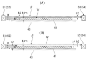
- FIG. 12 is a partial cross-sectional view and a partial perspective view illustrating the edge structure of the continuous laminate W in which the base paper 1 and the base paper 2 are glued.
- FIG. 12A shows a cross section of an edge portion that has been normally glued
- FIGS. 12B and 12C show the shape of the edge portion in which a gluing failure has occurred.
- a lightweight gypsum board (hereinafter referred to as “lightweight gypsum board”) whose specific gravity is smaller than the standard gypsum board (specific gravity 0.7 to 0.8), the strength of the entire gypsum board In order to assure security, a base paper having a relatively large weight may be used. Therefore, even when a lightweight gypsum board is manufactured using such a base paper, a frequency of defective gluing is relatively high.
- Such a gypsum board product in which the peeling portion K remains is inevitably removed from the product group as a non-standard product or a defective product that cannot be shipped, resulting in an increase in manufacturing loss and a deterioration in manufacturing yield.
- Patent Document 1 Japanese Patent Application Laid-Open No. 2000-74646 (Patent Document 1) describes an edge angle detection device that detects an angle of an edge surface (side end surface) with an optical detection means in order to detect a molding failure of an edge portion of a gypsum board. ing.
- the edge angle detection device includes a light source such as a laser, a CCD imaging device, an image processing device, and the like.
- the light source continuously irradiates the imaging light to the side edge band of the continuous laminate, and the imaging device receives the reflected light of the edge surface and continuously captures the image of the edge portion.
- the image processing device performs image processing on the image of the edge surface, measures an apparent edge width, and detects an edge angle based on the measured value of the edge width.
- Patent Document 2 describes a surface inspection apparatus intended to detect a defect occurring at the edge or surface of the continuous laminate by an optical detection means.
- This inspection apparatus receives a reflected light from a continuous laminate and a projector that irradiates the edge or surface of the continuous laminate with linear or planar light to expose a bright line or pattern on the edge or surface. It is composed of a light receiver that images bright lines or patterns on the continuous laminate and detects inclinations or fluctuations of bright lines or patterns appearing at the edge or surface by arithmetic processing or numerical analysis.
- an edge angle detection device Patent Document 1 (Japanese Patent Laid-Open No. 2000-74646) that detects an edge angle defect cannot detect a pasting defect on an upper paper base paper and a lower paper base paper. Even if a change or variation in the edge angle associated with a gluing failure can be detected by the edge angle detection device, it cannot be determined whether this is due to a gluing failure. No gluing failure can be detected by this edge angle detection device.
- Patent Document 2 a surface inspection apparatus disclosed in Japanese Patent Laid-Open No. 5-346319 (Patent Document 2) that optically forms bright lines or patterns on the edge or surface of a continuous laminate, and detects inclination or fluctuation of the bright lines or patterns by arithmetic processing. According to the above, it may be possible to detect an abnormality of the continuous laminate by changing the pattern. However, it cannot be determined whether or not this type of abnormality is a gluing defect. Therefore, even with the surface inspection apparatus of Patent Document 2, a gluing defect cannot be detected.
- the devices of Patent Documents 1 and 2 irradiate imaging light from a light source or a projector onto a continuous laminated body, and form an image of reflected light of the continuous laminated body on an imaging unit of the imaging apparatus or light receiver. Since it is a structure which detects the defect of a product, the environment or conditions which can discriminate
- peeling at the glued portion occurs not only immediately after gluing but also during drying and curing of the slurry.
- the peeling part generated immediately after gluing may re-adhere naturally during the drying / curing process of the slurry. Therefore, it is extremely difficult to predict in advance where the peeling occurs on the production line. For this reason, it is desirable to detect a glue failure at a plurality of locations on the production line.
- Patent Document a detection device or inspection device that irradiates a continuous laminate with imaging light and forms an image of the reflected light (Patent Document) If 1 and 2) are installed at a plurality of locations in the gypsum board manufacturing apparatus, not only the structure of the gypsum board manufacturing apparatus is complicated, but also the initial equipment cost or initial investment of the entire apparatus is increased.
- the present invention has been made in view of such problems, and the object of the present invention is to be able to detect early and surely a gluing failure of an upper paper base paper and a lower paper base paper with a simple configuration, and , A gluing defect detection system and a gluing defect detection which can relatively easily separate a plurality of detection device systems for detecting a gluing defect at a plurality of positions on a gypsum board production line spaced in the conveying direction of the continuous laminate. It is to provide a method.
- the present invention is to paste the edges of the upper paper and the lower paper with the gypsum slurry sandwiched between the lower paper and the upper paper of the base paper for gypsum board, Is formed in a gypsum board manufacturing apparatus configured to transport the laminated body by a molding belt, and optically detects a pasting failure of the pasting portion of the upper paper and the lower paper.
- a light emitting unit that is disposed on one side of the continuous laminate and irradiates a laser beam extending in a direction intersecting a conveying direction of the molding belt toward an edge of the continuous laminate;
- a light receiving part that is disposed on the opposite side of the continuous laminate so as to face the light emitting part, and that receives the laser light of the light emitting part,
- a controller for determining the occurrence of a gluing failure when the height of the laser beam blocked by the continuous laminate exceeds a predetermined value or a predetermined ratio;
- the laser beam is positioned so as to pass at least partially above the upper surface of the continuous laminate and to be partially blocked by the ridges on the edge of the continuous laminate.
- the present invention also provides a continuous cross section formed by gluing the edges of the upper paper and the lower paper in a state where the gypsum slurry is sandwiched between the lower paper and the upper paper of the base paper for gypsum board to form the edge cross section of the gypsum board.
- An optical detection means is provided in a gypsum board manufacturing apparatus configured to form a laminated body and transport the laminated body by a molding belt, and an optical detection means detects an adhesive failure in the pasting portion of the upper paper and the lower paper.
- the gluing defect detection method to detect By the light emitting part arranged on one side of the continuous laminate, the laser beam extending in the direction intersecting the conveying direction of the molding belt is irradiated toward the edge of the continuous laminate, Positioning the laser beam such that the laser beam passes at least partially above the upper surface of the continuous laminate and is partially blocked by a ridge at the edge of the continuous laminate; By receiving the laser light of the light emitting unit by the light receiving unit disposed on the opposite side of the continuous laminate facing the light emitting unit, There is provided a gluing failure detection method characterized in that the amount of light received by the light receiving unit is measured and the presence or absence of occurrence of gluing failure is determined based on the presence or absence of a decrease in received light amount by a predetermined value or a predetermined ratio or more.
- the gluing portion of the upper paper and the lower paper is at least 5 to 10% of the thickness of the continuous laminate (gypsum board thickness), or It has the property of raising 10% or more.
- the laser light projected by the light emitting portion passes at least partially above the upper surface of the continuous laminate and is received by the light receiving portion, but the edge of the continuous laminate is raised. Then, the laser beam is partially blocked by the ridges on the edge.
- the peeling at the gluing location occurs not only immediately after gluing but also during the drying / curing of the slurry on the molding belt. It is desirable to detect the presence or absence of the occurrence of a gluing defect.
- the pair of the light emitting unit and the light receiving unit may be arranged at any position on the gypsum board production line as a detection device system. Can be separated relatively easily. Therefore, according to the above configuration of the present invention, a plurality of detection device systems for detecting a gluing failure at a plurality of positions on the gypsum board production line can be relatively easily provided on the gypsum board production line.
- the present invention provides a gypsum board manufacturing apparatus having a gluing failure detection system configured as described above.
- the gypsum board manufacturing apparatus is a lower paper having a basis weight of 170 to 300 g / m 2 (for example, a lower paper having a paper thickness and a basic weight of 0.3 mm or more (0.4 mm or less) and 200 g / m 2 ). ) Is supplied to the lower paper transport line.
- the present invention provides a gypsum board manufacturing method using the gluing failure detection method configured as described above.
- a base paper having a basis weight of 170 to 300 g / m 2 (for example, a base paper having a paper thickness and basis weight of 0.3 mm or more (0.4 mm or less) and 200 g / m 2 ) is used as a raw material.
- the pasting failure of the upper base paper and the lower base paper can be detected quickly and reliably with a simple configuration, and in the transport direction of the continuous laminate.
- a plurality of detection device systems for detecting a pasting failure at a plurality of positions on the gypsum board production line at intervals can be relatively easily provided.
- FIG. 1 is a partial cross-sectional view of a gypsum board illustrating various forms of an edge portion of the gypsum board.
- FIG. 2 is a partial cross-sectional view of the gypsum board manufacturing apparatus partially and schematically showing the manufacturing process of the gypsum board.
- FIG. 3 is a partial plan view of the gypsum board manufacturing apparatus partially and schematically showing the manufacturing process of the gypsum board.
- FIG. 4 is a cross-sectional view of the gypsum board manufacturing apparatus showing the positional relationship between the upstream light projecting laser and light receiving laser sensors and the continuous laminate.
- FIG. 1 is a partial cross-sectional view of a gypsum board illustrating various forms of an edge portion of the gypsum board.
- FIG. 2 is a partial cross-sectional view of the gypsum board manufacturing apparatus partially and schematically showing the manufacturing process of the gypsum board.
- FIG. 3 is a partial plan
- FIG. 5 is a schematic cross-sectional view for explaining the principle of a gluing failure detection system, and shows a method of detecting a gluing failure in a manufacturing process of a 9.5 mm gypsum board.
- FIG. 6 is a schematic cross-sectional view for explaining the principle of the gluing failure detection system, and shows a method of detecting a gluing failure in the manufacturing process of a 12.5 mm gypsum board.
- FIG. 7 is a diagram (time chart) illustrating changes in the light receiving rate and shielding rate of the laser beam, and shows a state where no gluing failure has occurred.
- FIG. 8 is a diagram (time chart) illustrating a change in the light receiving rate and shielding rate of the laser beam, and shows a state in which unevenness or unevenness that does not result in poor gluing occurs at the edge of the continuous laminate.
- FIG. 9 is a diagram (time chart) illustrating changes in the light receiving rate and shielding rate of the laser beam, and shows a state in which a gluing failure has occurred immediately after gluing.
- FIG. 10 is a diagram (time chart) illustrating changes in the light receiving rate and shielding rate of the laser beam, and shows a state in which a gluing failure has occurred in the process of transporting the continuous laminate.
- FIG. 11 is a diagram (time chart) illustrating changes in the laser beam receiving rate and shielding rate, and shows a state in which a gluing failure that occurs immediately after gluing is detected even in the process of transporting the continuous laminate.
- FIG. 12 is a partial cross-sectional view and a partial perspective view illustrating an edge structure of a continuous laminate in which a base paper and an upper base paper are glued.
- FIG. 12A shows a normal glued edge. A cross-section is shown, and FIGS. 12B and 12C illustrate the form of an edge portion where a defective gluing has occurred.
- a plurality of light emitting units are arranged at intervals in the conveying direction of the molding belt, a plurality of light receiving units are arranged at intervals in the conveying direction of the molding belt, and a plurality of lasers Light is irradiated to the continuous laminate in the upstream region and downstream region of the molding belt.
- each laser beam has a horizontal optical axis perpendicular to the conveying direction of the molding belt.
- the gluing failure detection system when occurrence of gluing failure is determined based on the amount of received light detected by at least one of the plurality of light receiving units, the occurrence of gluing failure is visually or audibly detected by a display unit, an alarm unit, or the like. Notification (display or alarm) is performed by the notification means.
- the gluing failure detection system is configured such that when all of the determination results of occurrence of gluing failure based on the amount of received light detected by each light receiving unit indicate occurrence of gluing failure, the occurrence of gluing failure is indicated by display means or alarm means. Display or alarm.
- the amount of light received by the light receiving unit is input to the control device as a measured value.
- the control device sets a reference value of the amount of light received by the light receiving unit when it is normal, and compares the measured value of the amount of received light detected by the light receiving unit with the reference value to determine whether or not a gluing defect has occurred.
- the amount of light received by the light receiving unit when it is normal is set in advance before the start of manufacture based on the thickness of the gypsum board to be manufactured, for example, or the amount of received light that the gluing failure detection system regularly detects after the start of manufacture Based on the above, the initial setting or setting change is made after the start of manufacture.
- the gluing failure detection system displays or warns the occurrence of gluing failure by the display means or alarm means of the control device when the measured value of the received light amount is reduced to a predetermined ratio or less of the reference value.
- the predetermined ratio is set to a value within a range of 95 to 85%, for example, 90%. This ratio or ratio is of a nature that can be appropriately set and changed based on the thickness, type, etc. of the gypsum board.
- the control device includes a control / arithmetic unit, a storage unit, and a comparison determination unit.
- the control / calculation unit controls the operation of the light emitting unit and the light receiving unit, receives the detection value of the light receiving unit, and calculates the measurement value of the amount of received light.
- the storage unit stores, as a reference value, the amount of light received by the light receiving unit during normal operation, and stores a determination threshold value set based on the reference value so as to determine a pasting failure.
- the comparison / determination unit compares the measured value and the reference value based on the determination threshold value, and determines whether or not there is a pasting failure.
- the control device further includes means for displaying or alarming the occurrence of a gluing failure when the comparison / determination unit determines the occurrence of gluing failure.
- FIG. 1 is a partial cross-sectional view of a gypsum board illustrating various forms of the edge part of the gypsum board.
- the plaster board B having a thickness t has a structure in which a gypsum core C made of a hardened gypsum slurry is covered with upper and lower gypsum board base papers, that is, a lower base paper 1 and an upper base paper 2.
- FIG. 1 (A) shows a gypsum board B having a square edge.
- the edge portion E of the gypsum board B has an edge angle ⁇ set at a right angle.
- the base paper 1 is bent at the corners e1 and e2.
- the back surface edge portion (lower surface edge portion in FIG. 1) of the upper paper base paper 2 to which the paste is applied or applied is overlapped with the upper surface of the edge portion of the lower paper base paper 1 to form the glue portion G.
- FIG. 1 (A) shows a gypsum board B having a square edge.
- the edge portion E of the gypsum board B has an edge angle ⁇ set at a right angle.
- the base paper 1
- FIG. 1B shows a gypsum board B having a bevel edge.
- the base paper 1 is folded at corners e3, e4, e5, and the back edge of the base paper 2 coated or coated with glue is overlapped on the top of the edge of the base paper 1 to form a glue part G. Is done.
- FIG. 1C shows a gypsum board B having a tapered edge.
- the base paper 1 is folded at e6, e7, e8, and the back edge of the base paper 2 coated or coated with glue is overlapped on the top of the edge of the base paper 1 to form a gluing part G. .
- FIGS. 2 and 3 are a partial cross-sectional view and a partial plan view of the gypsum board manufacturing apparatus partially and schematically showing the manufacturing process of the gypsum board.
- the base paper 1 fed from a base paper roll (not shown) of the base paper stand is supplied onto the paper feed table 9 of the gypsum board manufacturing apparatus and conveyed on the manufacturing line in the direction of the arrow.
- a broken line (score) is engraved on the base paper 1 by a scoring device or a grinding device (not shown). For example, in the case of a square edge, the broken line is formed at a position corresponding to the corners e1 and e2.
- a mixing stirrer (mixer) 3 is arranged above the lower paper feed line, and is a powder raw material P such as calcined gypsum, adhesion aid, curing accelerator, additive, admixture, foam F, and liquid raw material (water) Q.
- the mixing stirrer 3 kneads these raw materials, and discharges a slurry (calcined gypsum slurry) S onto the lower paper base paper 1 through the pipelines 4 (4a, 4b, 4c).
- the pipeline 4a discharges a slurry S having a relatively low specific gravity to the central region in the width direction of the lower paper base paper 1, and the pipes 4b and 4c are relatively high at the edge portions (edge regions) on both sides of the lower paper base paper 1.
- Each of the specific gravity slurries S is discharged.
- the base paper 1 travels on the production line together with the slurry S, and the edge portions on both sides of the base paper 1 are bent upward by the guide members 5.
- the upper base paper 2 fed from the base paper roll (not shown) of the upper paper stand is fed onto the slurry S via the supply roller 7.
- a gluing device 20 for applying or applying a predetermined amount of glue to both edges of the upper base paper 2 is disposed in the vicinity of the supply roller 7.
- the gluing device 20 has a glue supply device 21 that continuously feeds glue from the upper side to the back surface edge of the base paper 2.
- a glue supply pipe 23 is connected to the glue supply device 21, and the glue supply pipe 23 is connected to a glue supply source (not shown).
- the base paper 1, the slurry S, and the base paper 2 are laminated by the upper and lower surface plates 8 and pass through the gypsum board molding apparatus 30 as a continuous laminated body W having a three-layer structure.
- the molding apparatus 30 includes upper and lower horizontal plates 31 and 32.
- the lower plate 32 is fixed horizontally to a machine frame (not shown) of the gypsum board manufacturing apparatus so as to horizontally transport the base paper 1.
- the elevating drive device 33 is disposed on the upper side of the upper plate 31 with an interval and is connected to the upper plate 31.
- the level of the upper plate 31 is finely adjusted by the elevating drive device 33, and the height dimension (gate dimension) J of the molding gate 34 formed between the plates 31, 32 is the lower base paper 1, the slurry S and the upper paper. It is strictly controlled so that an appropriate molding pressure acts on the continuous laminated body W of the base paper 2.
- the continuous laminated body W passes through the molding gate 34 and is molded into a continuous strip-shaped plate having a desired plate thickness
- the continuous laminated body W that has passed through the molding apparatus 30 is conveyed toward the subsequent process (rough cutting process) by the upper traveling belt 41 of the molding belt 40 constituting the belt conveyor apparatus, and the curing reaction of the slurry S is performed on the molding belt 40.
- Proceed with Rough cutting rollers 45 and 46 are formed by roughly cutting a continuous belt-like laminated body in which the slurry curing reaction has progressed, and thereby covering a core (core) mainly composed of gypsum with a base paper for gypsum board. That is, an original plate of gypsum board is formed.
- the gypsum board original plate is passed through a dryer (indicated by an arrow R in FIGS. 2 and 3), forcedly dried, and then cut into a predetermined product length, thus producing a gypsum board product.
- the upstream and downstream light projecting laser sensors 51 and 52 and the light receiving laser sensors 53 and 54 constituting the defective pasting detection system 50 are disposed outside the molding belt 40.
- the molding apparatus 30 and the rough cutting rollers 45 and 46 are separated by a distance D1.
- the upstream sensor pairs 51 and 53 and the downstream sensor pairs 52 and 54 are separated by a distance X in the transport direction.
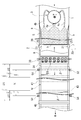
- FIG. 4 is a cross-sectional view of the gypsum board manufacturing apparatus showing the positional relationship between the upstream laser projector 51 and light receiving laser sensor 53 and the continuous laminate W. As shown in parentheses in FIG. 4, the light emitting laser sensor 52 and the light receiving laser sensor 54 in the downstream area have substantially the same configuration as the sensors 51 and 53 in the upstream area.
- Bearings 62 and 63 are attached to the left and right horizontal members 61 constituting the machine frame 60 of the gypsum board manufacturing apparatus.
- the bearings 62 and 63 rotatably support the upper and lower driven rollers 43 and 44 of the belt conveyor device.
- the molding belt 40 is composed of an endless belt that constitutes an upper traveling belt 41 and a lower traveling belt 42.
- the molding belt 40 is wound around a roller group including a number of driven rollers 43 and 44 and a driving roller (not shown).
- the belt conveyor device has a drive device (not shown), and the drive device rotates the drive roller to travel the upper traveling belt 41 in the transport direction and reversely travel the lower traveling belt 42.
- a bracket 64 having a sensor support base 65 is disposed on the upper surface of each horizontal member 61.
- the light projecting laser sensor 51 is mounted on the base 65 on one side (left side in FIG. 4), and the light receiving laser sensor 53 is mounted on the base 65 on the opposite side (right side in FIG. 4).
- the sensor 51 emits a visible light semiconductor laser beam ⁇ having a predetermined height H.
- the laser beam ⁇ has a horizontal optical axis orthogonal to the transport direction of the continuous laminate W.
- the sensor 53 includes a light receiving unit that faces the light emitting unit of the sensor 51. When the continuous laminated body W does not exist on the upper traveling belt 41, the sensor 53 receives the narrow and vertically long thin belt laser beam ⁇ having a predetermined height H as it is.
- the lower edge of the laser beam ⁇ is positioned at the same level as the upper surface of the upper traveling zone 41, and the height H of the laser beam ⁇ is set to 30 mm.
- the laser beam ⁇ is a thin linear light beam that can ignore the width dimension (the dimension of the laser beam ⁇ in the transport direction of the continuous laminated body W) in plan view (FIG. 3).
- the control unit 70 includes a control / calculation unit, a storage unit, a comparison determination unit, and a drive unit.
- the control / arithmetic unit controls the operation of the sensors 51 to 54 and receives the outputs (detection signals) of the sensors 53 and 54.
- the storage unit stores the received light amounts of the sensors 53 and 54 at the normal time as a reference value, and stores the received light amounts detected by the sensors 53 and 54 as measured values.
- the storage unit also stores a received light amount of 90% of the received light amount (reference value) of the sensors 53 and 54 at the normal time as a determination threshold value.
- the comparison / determination unit compares the measured value and the reference value based on the determination threshold value, and determines whether or not there is a pasting failure.
- the drive unit controls the operation of the touch panel display 71, the electronic sound alarm 72, and the like constituting the HMI (Human-Machine Interfaces).
- the control unit 70 is connected to the touch panel display 71 via the control signal line L3.
- the display device 71 is connected to the electronic sound alarm device 72 via the control signal line L4.
- the downstream sensors 52 and 54 are also connected to the control unit 70 by control signal lines L1 ′ and L2 ′.
- the control unit 70, the display device 71, and the alarm device 72 constitute a control device or a control system of the gluing failure detection system 50.
- FIG. 5 and 6 are schematic cross-sectional views for explaining the principle of the gluing failure detection system 50.
- FIG. 5 and 6 are schematic cross-sectional views for explaining the principle of the gluing failure detection system 50.
- the height h1 of the continuous laminated body W matches the plate thickness t of the gypsum board.
- the height H of the laser beam ⁇ is set to 30 mm
- the storage unit of the control unit 70 stores the amount of light received by the sensor 53 (54) at such a normal time as a reference value.
- the storage unit of the control unit 70 stores the amount of light received by the sensor 53 (54) thus changed as a measurement value.
- This is set as a reference indicating the occurrence of defects. That is, when the condition ⁇ h ⁇ h1 ⁇ about 0.10 (about 10%) is satisfied (ie, the height reduction value ⁇ h of the laser beam ⁇ is about 0.95 mm (FIG. 5B)). Or, when reaching a value of about 1.25 mm (FIG. 6B) or more), it is set so as to determine that a gluing failure has occurred.
- control unit 70 sets the received light amount of 90% of the received light amount (reference value) of the sensor 53 (54) at the normal time as the determination threshold value, stores the received light amount in the storage unit, and controls the control unit.
- the comparison determination unit 70 determines that a gluing failure has occurred when the amount of light received by the sensor 53 has decreased to 90% or less.
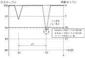
- FIGS. 7 to 11 are diagrams (time charts) illustrating changes in the amount of received light of the laser beam ⁇ .
- the diagrams shown in FIGS. 7 to 11 are displayed on the screen of the touch panel display 71 (FIG. 4). Is done. 7 to 11, the vertical axis is an index indicating the light receiving rate (or light receiving ratio) ⁇ and the shielding rate (or shielding ratio) ⁇ of the laser beam ⁇ detected by the light receiving units of the sensors 53 and 54.
- the light receiving rate ⁇ is a measured value / reference value
- the shielding rate ⁇ is [1 ⁇ measured value] / reference value.
- the time at which the upstream sensors 51 and 53 detect a certain part of the continuous laminate W A time difference ⁇ T between T1 and time T2 when the downstream side sensors 52 and 54 detect the same part is determined by the conveyance speed of the belt conveyor device 40 and the distance X.
- FIG. 7 shows a normal state in which no gluing failure has occurred in the continuous laminate W, that is, a state in which the received light amount corresponding to the reference value is detected by the sensors 53 and 54.
- the control unit 70 does not activate the electronic sound alarm 72, and therefore the electronic sound alarm 72 does not generate an alarm sound.
- the sensor 53 detects a received light amount (reference light rate ⁇ ⁇ 0.9 (90%)) of a reference value ⁇ 0.9 or less, and the sensor 54 receives a received light amount (received light amount exceeding the reference value ⁇ 0.9).
- the state where the rate ⁇ > 0.9 (90%)) is detected is shown.
- the phenomenon in which different amounts of received light are detected in this way is observed when the protruding portion K (FIG. 12) occurs immediately after gluing and then the protruding portion K is reduced as the slurry S is dried and cured.
- a state of ⁇ h ⁇ h1 ⁇ about 0.10 occurs immediately after gluing, and therefore it can be determined that a gluing failure has occurred in the continuous laminated body W.
- the alarm device 72 is activated, and the electronic sound alarm device 72 generates an alarm sound informing a worker or the like of the occurrence of a gluing failure.
- the sensor 54 detects a light reception amount (light reception rate ⁇ ⁇ 0.9 (90%)) of a reference value ⁇ 0.9 or less, and the sensor 53 receives a light reception amount (light reception) exceeding the reference value ⁇ 0.9.
- the state where the rate ⁇ > 0.9 (90%)) is detected is shown.
- the phenomenon in which different amounts of received light are detected in this manner is a normal sizing state immediately after gluing, but occurs when a peeling portion K (FIG. 12) occurs during drying / curing of the slurry S or immediately after gluing. This can be seen when the bulge of the minute peeled portion K increases as the slurry S dries and hardens.
- a state of ⁇ h ⁇ h1 ⁇ about 0.10 occurs on the molding belt 40, and therefore, it can be determined that a pasting failure has occurred in the continuous laminated body W.
- the electronic sound alarm device 72 is activated, and the electronic sound alarm device 72 generates an alarm sound that informs an operator of the occurrence of a gluing failure.
- FIG. 11 shows a typical gluing failure form in which the peeling portion K (FIG. 12) occurs immediately after gluing and remains without being reduced even when the slurry S is dried and cured. That is, in the detection result shown in FIG. 11, both of the sensors 53 and 54 detect the received light amount (light reception rate ⁇ ⁇ 0.9 (90%)) of the reference value ⁇ 0.9 or less.
- the control unit 70 activates an electronic sound alarm device 72, and the electronic sound alarm device 72 generates an alarm sound that informs an operator or the like that a gluing failure has occurred.
- the control unit 70 always displays the detection results of the sensors 53 and 54 shown in FIG. 7 to FIG. 11 on the screen of the touch panel display 71. It can be recognized immediately after the occurrence.
- the operator confirms the form and degree of the glue failure by the screen display of the touch panel display 71, and the glue supply amount of the glue feeder 21 of the glue device 20 in order to eliminate the glue failure state. Adjust etc.
- a digital laser sensor LV-300H manufactured by Keyence Corporation can be suitably used as the light projecting laser sensor 51.
- the light receiving laser sensor 53 for example, a digital laser sensor LV-300H manufactured by Keyence Corporation can be preferably used.
- a programmable logic controller (PLC) constituting the control unit 70 for example, a MELSEC-Q series sequencer manufactured by Mitsubishi Electric Corporation can be suitably used.
- the touch panel display 71 for example, a VT-3 series touch panel display manufactured by Keyence Corporation can be preferably used, and for example, a signal phone manufactured by Patlite can be preferably used as the electronic sound alarm 72. .
- the lower base paper 1 is continuously supplied in the conveying direction of the belt conveyor device 40, and the mixing agitator 3 continuously discharges the slurry S onto the lower base paper 1.
- the left and right edges of the base paper 1 on which a fold line (score) is engraved by a scoring device (not shown) are bent upward by the guide member 5.
- the upper paper base paper 2 having the glue applied or applied to the left and right edges by the gluing device 20 is stacked on the lower paper base paper 1 and the slurry S.
- the base papers 1 and 2 and the slurry S are pressed and shaped by the surface plate 8 and the molding apparatus 30 to be formed into a continuous laminated body W having a three-layer structure.
- the continuous laminated body W that has passed through the molding gate 34 of the molding apparatus 30 is continuously conveyed by the upper traveling belt 41 of the molding belt 40, and the curing reaction of the slurry S proceeds during conveyance.
- the continuous laminated body W is roughly cut by rough cutting rollers 45 and 46, and finally processed as a gypsum board product by a subsequent drying step and cutting step.
- the defective pasting detection system 50 is always operated during the manufacture of such a gypsum board, and the light projecting laser sensors 51 and 52 constantly irradiate the laser beam ⁇ traversing the continuous laminated body W.
- the light receiving laser sensors 53 and 54 constantly receive the laser beam ⁇ , and continuously output the received light amount detection value of the laser beam ⁇ to the control / calculation unit of the control unit 70.
- the control unit 70 displays a numerical value and a graph of the light receiving rate ⁇ (and the shielding rate ⁇ ) on the screen of the touch panel display 71 based on the detection values of the sensors 53 and 54.
- the control unit 70 determines the occurrence of gluing failure at a predetermined time interval (time interval corresponding to the control cycle time) based on the light reception rate ⁇ (or shielding rate ⁇ ) obtained from the detection values of the sensors 53 and 54.
- control unit 70 determines that a gluing failure has occurred, the control unit 70 activates an electronic sound alarm 72, and the electronic sound alarm 72 generates an alarm sound that informs the worker of the occurrence of a gluing failure.
- the worker recognizes the generation of the alarm sound, confirms the form and degree of gluing failure by the screen display of the touch panel display 71, and also eliminates the state of gluing failure, the glue of the glue supply device 21 of the gluing device 20 Adjust the supply amount.
- a gluing defect detection system 50 it is possible to detect the presence or absence of gluing defects at a plurality of positions separated in the transport direction of the continuous laminated body W. It is also possible to detect a gluing failure in a form that occurs, and thus it is possible to reliably detect a gluing failure. Further, according to the gluing defect detection system 50 having the above-described configuration, it is possible to detect gluing defects at arbitrary positions suitable for individual manufacturing processes by arranging the sensors 51 to 54 at appropriate positions on the production line. Since the number of sensors can be increased to detect a pasting failure at a large number of three or more places, it is extremely advantageous from a practical and economical viewpoint.
- the extraordinary ratio ratio of extraordinary articles out of the number of products manufactured within a certain period related to defective gluing is reduced to about 1/100 by adopting the gluing defect detection system 50. It has become possible to significantly reduce the yield rate. Therefore, the adoption of the gluing failure detection system 50 having the above-described configuration is extremely useful for improving the productivity of the gypsum board.
- the base paper 1 in a standard gypsum board, paper having a large paper thickness and a large basis weight is used as the base paper 1.
- the paper thickness and basis weight of the base paper 1 is about 0.19 mm to about 0.21 mm, about 100 to about 200 g / m 2
- the high specific gravity gypsum board or The thickness and basis weight of the base paper 1 used for the production of the lightweight gypsum board are about 0.34 to about 0.36 mm, about 170 to about 300 g / m 2 , preferably about 200 to about 300 g / m 2.
- the base paper used for manufacture of such a gypsum board has the property of warping easily.
- an uncured slurry with a high specific gravity pushes up the bent portion of the lower paper base paper 1, and accordingly, a phenomenon that the upper paper base paper 2 is pushed up easily occurs. Due to the paper quality peculiar to such a high specific gravity gypsum board and the behavior or properties of the high specific gravity slurry, troubles in poor gluing are likely to occur in the production of the high specific gravity gypsum board.
- the form of poor gluing that occurs during the production of high-density gypsum board or lightweight gypsum board is often after the upper paper base paper and the lower paper base paper transiently bonded immediately after gluing, In this configuration, the glued portion is peeled off during conveyance by the molding belt 40.
- Such a pasting failure form could not be detected by a conventional pasting failure detection system.
- the gluing failure detection system 50 having the above-described configuration is extremely advantageous because the gluing failure of such a form can be reliably detected as shown in FIG.
- the light receiving rate 0.9 (90%) is adopted as the determination threshold value for determining the gluing failure.
- the determination threshold value includes the structure of the gypsum board manufacturing apparatus, the type of gypsum board, and the like. The setting can be changed as appropriate according to the situation.
- the upstream sensor 53 detects a light reception amount (light reception rate ⁇ ⁇ 0.9 (90%)) of the reference value ⁇ 0.9 or less, and the downstream sensor 54 detects the reference value ⁇ 0.9. Even in a state where a received light amount exceeding 0.9 (light reception rate ⁇ > 0.9 (90%)) is detected, it is determined that a gluing failure has occurred. It is also possible to determine that no gluing failure has occurred as a result of spontaneous elimination with the drying / curing of S.
- the detection apparatus system (light projection laser sensor and light reception laser sensor) is arrange
- the control system configured to determine the pasting failure based on the light receiving rate has been described, but the present invention is not limited to this, and the abnormal value is fixed to a constant value.
- the abnormal value is fixed to a constant value.
- the gluing failure detection system 50 uses a laser beam ⁇ having a horizontal optical axis orthogonal to the transport direction, but the laser beam has a predetermined angle with respect to the transport direction. It is also possible to orient in a direction inclined in the direction.
- the production of gypsum board having a thickness of 9.5 mm and 12.5 mm has been described as an example.
- the present invention is not limited to this, and 6 mm, 15 mm, 18 mm, 21 mm. It can be applied to the production of gypsum board with various thicknesses, such as gypsum board with thickness of 25mm.
- the present invention molds a continuous laminate in which the edge of the gypsum board is formed by gluing the edges of the gypsum board with the gypsum slurry sandwiched between the gypsum board base paper and the gypsum slurry. It is provided in a gypsum board manufacturing apparatus configured to be conveyed by a belt, and is applied to a gluing failure detection system and a gluing failure detection method for detecting a gluing failure of a gluing portion of upper paper and lower paper by an optical detection means.
- the pasting failure of the upper base paper and the lower base paper can be detected quickly and reliably with a simple configuration, and moreover, a plurality of plasterboard production lines can be detected.
- the detection device system can be arranged relatively easily at a plurality of positions on the gypsum board production line spaced in the conveying direction of the continuous laminate, and its practical value Is remarkable.
Landscapes
- Engineering & Computer Science (AREA)
- General Health & Medical Sciences (AREA)
- Pathology (AREA)
- Health & Medical Sciences (AREA)
- Life Sciences & Earth Sciences (AREA)
- Chemical & Material Sciences (AREA)
- Analytical Chemistry (AREA)
- Biochemistry (AREA)
- Immunology (AREA)
- Physics & Mathematics (AREA)
- General Physics & Mathematics (AREA)
- Textile Engineering (AREA)
- Structural Engineering (AREA)
- Devices For Post-Treatments, Processing, Supply, Discharge, And Other Processes (AREA)
- Investigating Materials By The Use Of Optical Means Adapted For Particular Applications (AREA)
- Coating Apparatus (AREA)
- Laminated Bodies (AREA)
- Producing Shaped Articles From Materials (AREA)
- Length Measuring Devices By Optical Means (AREA)
Abstract
Description
前記連続積層体の片側に配置され、前記成型ベルトの搬送方向と交差する方向に延びるレーザー光を前記連続積層体の縁部に向かって照射する発光部と、
前記発光部に対向して前記連続積層体の反対側に配置され、前記発光部のレーザー光を受光する受光部と、
前記連続積層体によって遮られた前記レーザー光の高さが所定値又は所定割合を超えるときに糊付け不良の発生を判定するための制御装置とを備え、
前記レーザー光は、少なくとも部分的に前記連続積層体の上面の上側を通過するとともに、前記連続積層体の縁部の隆起によって部分的に遮られるように位置決めされることを特徴とする糊付け不良検出システムを提供する。
前記連続積層体の片側に配置された発光部によって、前記成型ベルトの搬送方向と交差する方向に延びるレーザー光を前記連続積層体の縁部に向かって照射し、
前記レーザー光が少なくとも部分的に前記連続積層体の上面の上側を通過するとともに、前記連続積層体の縁部の隆起によって前記レーザー光が部分的に遮られるように、前記レーザー光を位置決めし、
前記発光部に対向して前記連続積層体の反対側に配置された受光部によって、前記発光部のレーザー光を受光し、
前記受光部の受光量を測定し、所定値又は所定割合以上の受光量低下の有無により糊付け不良発生の有無を判定することを特徴とする糊付け不良検出方法を提供する。
2 上紙原紙
3 混合攪拌機
8 定盤
20 糊付け装置
21 糊供給装置
30 石膏ボード成型装置
40 成型ベルト
41 上側走行帯
42 下側走行帯
45、46 粗切断装置
50 糊付け不良検出システム
51、52 投光レーザーセンサ
53、54 受光レーザーセンサ
60 機枠
70 制御ユニット
71 タッチパネル表示器
72 電子音警報器
B 石膏ボード
C 石膏コア
E エッジ部
G 糊付け部
K 剥離部又は空隙部
S スラリー
W 連続積層体
X 距離
t 板厚
h 高さ
Δh 高さ低減値
α エッジ角度
β 可視光半導体レーザービーム
Claims (19)
- 石膏ボード用原紙の下紙及び上紙の間に石膏スラリーを挟んだ状態で上紙及び下紙の縁部を糊付けして、石膏ボードの縁部断面を形成してなる連続積層体を形成し、該積層体を成型ベルトによって搬送するように構成された石膏ボード製造装置に設けられ、前記上紙及び下紙の糊付け部の糊付け不良を光学的検出手段により検出する糊付け不良検出システムにおいて、
前記連続積層体の片側に配置され、前記成型ベルトの搬送方向と交差する方向に延びるレーザー光を前記連続積層体の縁部に向かって照射する発光部と、
前記発光部に対向して前記連続積層体の反対側に配置され、前記発光部のレーザー光を受光する受光部と、
前記連続積層体によって遮られた前記レーザー光の高さが所定値又は所定割合を超えるときに糊付け不良の発生を判定するための制御装置とを備え、
前記レーザー光は、少なくとも部分的に前記連続積層体の上面の上側を通過するとともに、前記連続積層体の縁部の隆起によって部分的に遮られるように位置決めされることを特徴とする糊付け不良検出システム。 - 複数の前記発光部が前記成型ベルトの搬送方向に間隔を隔てて配置され、複数の前記受光部が前記成型ベルトの搬送方向に間隔を隔てて配置されることを特徴とする請求項1に記載の糊付け不良検出システム。
- 前記レーザー光は、前記成型ベルトの搬送方向に直交する水平な光軸を有することを特徴とする請求項1又は2に記載の糊付け不良検出システム。
- 前記制御装置は、正常時に前記受光部が受光すべき受光量を基準値として設定し、前記受光部が検出した受光量を前記基準値と比較して、糊付け不良発生の有無を判定することを特徴とする請求項1乃至3のいずれか1項に記載の糊付け不良検出システム。
- 正常時に前記受光部が受光すべき受光量は、製造すべき石膏ボードの板厚に基づいて製造開始前に予め設定され、或いは、糊付け不良検出システムが製造開始後に定常的に検出する受光量に基づいて製造開始後に初期設定され又は設定変更されることを特徴とする請求項1乃至4のいずれか1項に記載の糊付け不良検出システム。
- 前記制御装置は、前記発光部及び前記受光部の作動を制御するとともに、前記受光部の検出値を受信して受光量の測定値を演算する制御・演算部と、
正常時に前記受光部が受光すべき受光量を基準値として記憶するとともに、糊付け不良を判定するための判定しきい値を記憶する記憶部と、
前記測定値と前記基準値とを比較し、判定しきい値に基づいて糊付け不良発生の有無を判定する比較判定部と、
該比較判定部が糊付け不良の発生を判定したときに糊付け不良の発生を表示又は警報する手段とを有することを特徴とする請求項1乃至5のいずれか1項に記載の糊付け不良検出システム。 - 石膏ボード用原紙の下紙及び上紙の間に石膏スラリーを挟んだ状態で上紙及び下紙の縁部を糊付けして、石膏ボードの縁部断面を形成してなる連続積層体を形成し、該積層体を成型ベルトによって搬送するように構成された石膏ボード製造装置に光学的検出手段を設け、前記上紙及び下紙の糊付け部の糊付け不良を光学的検出手段によって検出する糊付け不良検出方法において、
前記連続積層体の片側に配置された発光部によって、前記成型ベルトの搬送方向と交差する方向に延びるレーザー光を前記連続積層体の縁部に向かって照射し、
前記レーザー光が少なくとも部分的に前記連続積層体の上面の上側を通過するとともに、前記連続積層体の縁部の隆起によって前記レーザー光が部分的に遮られるように、前記レーザー光を位置決めし、
前記発光部に対向して前記連続積層体の反対側に配置された受光部によって、前記発光部のレーザー光を受光し、
前記受光部の受光量を測定し、所定値又は所定割合以上の受光量低下の有無により糊付け不良発生の有無を判定することを特徴とする糊付け不良検出方法。 - 複数の前記発光部を前記成型ベルトの搬送方向に間隔を隔てて配置し、複数の前記受光部を前記成型ベルトの搬送方向に間隔を隔てて配置し、水平な光軸を有する各レーザー光を前記成型ベルトの上流域及び下流域において前記連続積層体の照射することを特徴とする請求項7に記載の糊付け不良検出方法。
- 前記受光部の受光量を測定値として制御装置に入力し、正常時に前記受光部が受光すべき受光量を基準値として設定し、前記受光部により検出された受光量の測定値を前記制御装置により前記基準値と比較し、前記測定値が前記基準値の所定割合以下に低減したとき、糊付け不良の発生を前記制御装置の表示手段又は警報手段により表示又は警報することを特徴とする請求項7又は8に記載の糊付け不良検出方法。
- 前記所定割合を95~85%の範囲内の値に設定したことを特徴とする請求項9に記載の糊付け不良検出方法。
- 複数の前記受光部の少なくとも1つが検出した受光量に基づいて、糊付け不良の発生が判定されたときに、糊付け不良の発生を表示手段又は警報手段により表示又は警報することを特徴とする請求項8に記載の糊付け不良検出方法。
- 各々の受光部が検出した受光量に基づいて判定された糊付け不良発生の判定結果が、いずれも糊付け不良の発生を示すとき、糊付け不良の発生を表示手段又は警報手段により表示又は警報することを特徴とする請求項8に記載の糊付け不良検出方法。
- 石膏ボード製造開始後に前記受光部が定常的に受光する受光量を前記基準値として設定することを特徴とする請求項9又は10に記載の糊付け不良検出方法。
- 前記基準値は、製造すべき石膏ボードの板厚に基づいて製造開始前に予め設定されることを特徴とする請求項9又は10に記載の糊付け不良検出方法。
- 請求項1乃至6のいずれか1項に記載された糊付け不良検出システムを有する石膏ボード製造装置。
- 170~300g/m2の坪量を有する前記下紙を供給するための下紙供給装置を有することを特徴とする請求項15に記載の石膏ボード製造装置。
- 請求項7乃至14のいずれか1項に記載された糊付け不良検出方法を用いた石膏ボード製造方法。
- 170~300g/m2の坪量を有する前記下紙を原材料として前記石膏ボードを製造することを特徴とする請求項17に記載の石膏ボード製造方法。
- 比重0.9以上の高比重石膏ボード、或いは、比重0.6以下の軽量石膏ボードを製造することを特徴とする請求項17又は18に記載の石膏ボード製造方法。
Priority Applications (8)
| Application Number | Priority Date | Filing Date | Title |
|---|---|---|---|
| CN201480036321.5A CN105358965B (zh) | 2013-06-24 | 2014-05-23 | 涂胶不良检测系统以及涂胶不良检测方法 |
| CA2915444A CA2915444C (en) | 2013-06-24 | 2014-05-23 | Sizing defect detection system and sizing defect detection method |
| JP2015523921A JP6193995B6 (ja) | 2013-06-24 | 2014-05-23 | 糊付け不良検知システム及び糊付け不良検知方法 |
| US14/895,662 US9651500B2 (en) | 2013-06-24 | 2014-05-23 | Sizing defect detection system and sizing defect detection method |
| EP14817828.8A EP3015849B1 (en) | 2013-06-24 | 2014-05-23 | Glue-joint failure detection system and glue-joint failure detection method |
| KR1020157033020A KR102175505B1 (ko) | 2013-06-24 | 2014-05-23 | 풀칠 불량 검지 시스템 및 풀칠 불량 검지 방법 |
| RU2016101991A RU2016101991A (ru) | 2013-06-24 | 2014-05-23 | Система обнаружения размерного дефекта и способ обнаружения размерного дефекта |
| ES14817828T ES2771102T3 (es) | 2013-06-24 | 2014-05-23 | Sistema de detección de defectos en uniones encoladas y procedimiento de detección de defectos en uniones encoladas |
Applications Claiming Priority (2)
| Application Number | Priority Date | Filing Date | Title |
|---|---|---|---|
| JP2013-131749 | 2013-06-24 | ||
| JP2013131749 | 2013-06-24 |
Publications (1)
| Publication Number | Publication Date |
|---|---|
| WO2014208226A1 true WO2014208226A1 (ja) | 2014-12-31 |
Family
ID=52141578
Family Applications (1)
| Application Number | Title | Priority Date | Filing Date |
|---|---|---|---|
| PCT/JP2014/063628 Ceased WO2014208226A1 (ja) | 2013-06-24 | 2014-05-23 | 糊付け不良検知システム及び糊付け不良検知方法 |
Country Status (10)
| Country | Link |
|---|---|
| US (1) | US9651500B2 (ja) |
| EP (1) | EP3015849B1 (ja) |
| JP (1) | JP6193995B6 (ja) |
| KR (1) | KR102175505B1 (ja) |
| CN (1) | CN105358965B (ja) |
| CA (1) | CA2915444C (ja) |
| ES (1) | ES2771102T3 (ja) |
| RU (1) | RU2016101991A (ja) |
| TW (1) | TW201508263A (ja) |
| WO (1) | WO2014208226A1 (ja) |
Cited By (4)
| Publication number | Priority date | Publication date | Assignee | Title |
|---|---|---|---|---|
| WO2019082433A1 (ja) * | 2017-10-23 | 2019-05-02 | 吉野石膏株式会社 | 石膏ボードの製造方法、石膏ボード |
| CN111812106A (zh) * | 2020-09-15 | 2020-10-23 | 沈阳风驰软件股份有限公司 | 一种无线耳机外观面溢胶检测方法和检测系统 |
| US20220099589A1 (en) * | 2019-02-28 | 2022-03-31 | Yoshino Gypsum Co., Ltd. | Apparatus for inspecting plate-like bodies |
| JPWO2024038636A1 (ja) * | 2022-08-19 | 2024-02-22 |
Families Citing this family (10)
| Publication number | Priority date | Publication date | Assignee | Title |
|---|---|---|---|---|
| CN109203193B (zh) * | 2017-06-30 | 2020-07-24 | 平邑北新建材有限公司 | 一种纸面石膏板立边设备 |
| AU2019268718B2 (en) * | 2018-05-14 | 2024-07-25 | Yoshino Gypsum Co., Ltd. | Inspection device, plate-like object manufacturing device, inspection method, and plate-like object manufacturing method |
| CA3155174C (en) * | 2019-12-16 | 2024-06-25 | Stergios KARAKOUSSIS | Method for producing a cementitious board, apparatus for producing a cementitious board, and cementitious board |
| CN111999273B (zh) * | 2020-08-17 | 2023-12-08 | 无锡先导智能装备股份有限公司 | 物体缺陷检测方法、系统、装置、设备和存储介质 |
| US20240050978A1 (en) * | 2021-01-26 | 2024-02-15 | Yoshino Gypsum Co., Ltd. | Glue supply apparatus for gypsum board, gypsum board manufacturing apparatus, and gypsum board manufacturing method |
| CN113324589A (zh) * | 2021-06-08 | 2021-08-31 | 奇瑞商用车(安徽)有限公司 | 一种汽车零部件涂胶质量检测用具 |
| CN116331774B (zh) * | 2023-05-24 | 2023-09-15 | 泰山石膏(四川)有限公司 | 一种出板输送装置及方法 |
| CN117012309B (zh) * | 2023-06-27 | 2024-12-06 | 江苏大学 | 一种异质胶接接头耦合失效行为的损伤初始表征方法 |
| CN117226984B (zh) * | 2023-09-11 | 2026-03-27 | 淮南北新建材有限公司 | 一种传送系统及其控制方法、石膏板生产线 |
| CN118297940B (zh) * | 2024-05-30 | 2024-09-13 | 泰山石膏(宜宾)有限公司 | 一种石膏板生产线质量管控方法、装置、设备及介质 |
Citations (6)
| Publication number | Priority date | Publication date | Assignee | Title |
|---|---|---|---|---|
| JPH05346319A (ja) | 1992-06-15 | 1993-12-27 | Yamatake Honeywell Co Ltd | 板状連続物体の面検査装置 |
| JPH06171008A (ja) * | 1992-12-03 | 1994-06-21 | Yoshino Sekko Kk | 難燃性石膏ボード用原紙及び石膏ボード |
| JP2000074646A (ja) | 1998-08-28 | 2000-03-14 | Yoshino Gypsum Co Ltd | エッジ角度検出装置及びエッジ角度検出方法 |
| JP2003293515A (ja) * | 2002-03-28 | 2003-10-15 | Zero System:Kk | 石膏ボード |
| JP2008184206A (ja) * | 2007-01-31 | 2008-08-14 | Tokyo Denshi Kogyo Kk | 封筒フラップ封緘検査装置 |
| US20130061777A1 (en) * | 2011-09-14 | 2013-03-14 | Certainteed Gypsum, Inc. | System and Method for the Production of Gypsum Board Using Starch Pellets |
Family Cites Families (7)
| Publication number | Priority date | Publication date | Assignee | Title |
|---|---|---|---|---|
| US3695771A (en) | 1970-08-06 | 1972-10-03 | Andras M Bardos | Method and apparatus for inspecting surfaces |
| JPS5587907A (en) * | 1978-12-27 | 1980-07-03 | Fuji Photo Film Co Ltd | Device for continuously inspecting surface of object |
| DE19909518A1 (de) * | 1998-03-23 | 1999-10-07 | Heidelberger Druckmasch Ag | Verfahren und Vorrichtung zur Erfassung der Lage von gestapeltem Material |
| FI112684B (fi) * | 1999-03-23 | 2003-12-31 | Metso Paper Inc | Menetelmä paperi- tai kartonkirainan käyristymän mittaamiseksi ja säätämiseksi sekä paperi- tai kartonkikonelinja |
| CN202245471U (zh) * | 2011-08-29 | 2012-05-30 | 上海弘迈机械有限公司 | 残卷自动断纸抓尾接纸机构的检测机构 |
| CN202878834U (zh) * | 2012-10-20 | 2013-04-17 | 周玉兴 | 一种全自动pvc双贴面石膏板生产线 |
| CN203382146U (zh) * | 2013-07-02 | 2014-01-08 | 太仓北新建材有限公司 | 石膏板输送故障监测装置 |
-
2014
- 2014-05-23 US US14/895,662 patent/US9651500B2/en not_active Expired - Fee Related
- 2014-05-23 CN CN201480036321.5A patent/CN105358965B/zh not_active Expired - Fee Related
- 2014-05-23 JP JP2015523921A patent/JP6193995B6/ja active Active
- 2014-05-23 KR KR1020157033020A patent/KR102175505B1/ko active Active
- 2014-05-23 ES ES14817828T patent/ES2771102T3/es active Active
- 2014-05-23 EP EP14817828.8A patent/EP3015849B1/en active Active
- 2014-05-23 WO PCT/JP2014/063628 patent/WO2014208226A1/ja not_active Ceased
- 2014-05-23 RU RU2016101991A patent/RU2016101991A/ru not_active Application Discontinuation
- 2014-05-23 CA CA2915444A patent/CA2915444C/en active Active
- 2014-06-17 TW TW103120818A patent/TW201508263A/zh unknown
Patent Citations (6)
| Publication number | Priority date | Publication date | Assignee | Title |
|---|---|---|---|---|
| JPH05346319A (ja) | 1992-06-15 | 1993-12-27 | Yamatake Honeywell Co Ltd | 板状連続物体の面検査装置 |
| JPH06171008A (ja) * | 1992-12-03 | 1994-06-21 | Yoshino Sekko Kk | 難燃性石膏ボード用原紙及び石膏ボード |
| JP2000074646A (ja) | 1998-08-28 | 2000-03-14 | Yoshino Gypsum Co Ltd | エッジ角度検出装置及びエッジ角度検出方法 |
| JP2003293515A (ja) * | 2002-03-28 | 2003-10-15 | Zero System:Kk | 石膏ボード |
| JP2008184206A (ja) * | 2007-01-31 | 2008-08-14 | Tokyo Denshi Kogyo Kk | 封筒フラップ封緘検査装置 |
| US20130061777A1 (en) * | 2011-09-14 | 2013-03-14 | Certainteed Gypsum, Inc. | System and Method for the Production of Gypsum Board Using Starch Pellets |
Non-Patent Citations (1)
| Title |
|---|
| KISAKU FURUYA: "Recovery and Utilization of Gypsum", JOURNAL OF THE MINING AND MATERIALS PROCESSING INSTITUTE OF JAPAN, vol. 107, no. 2, February 1991 (1991-02-01), pages 154 - 159, XP055302827 * |
Cited By (10)
| Publication number | Priority date | Publication date | Assignee | Title |
|---|---|---|---|---|
| WO2019082433A1 (ja) * | 2017-10-23 | 2019-05-02 | 吉野石膏株式会社 | 石膏ボードの製造方法、石膏ボード |
| KR20200075823A (ko) * | 2017-10-23 | 2020-06-26 | 요시노 셋고 가부시키가이샤 | 석고 보드 제조방법 및 석고 보드 |
| JPWO2019082433A1 (ja) * | 2017-10-23 | 2020-11-19 | 吉野石膏株式会社 | 石膏ボードの製造方法、石膏ボード |
| JP7071750B2 (ja) | 2017-10-23 | 2022-05-19 | 吉野石膏株式会社 | 石膏ボードの製造方法、石膏ボード |
| KR102523140B1 (ko) | 2017-10-23 | 2023-04-17 | 요시노 셋고 가부시키가이샤 | 석고 보드 제조방법 및 석고 보드 |
| US20220099589A1 (en) * | 2019-02-28 | 2022-03-31 | Yoshino Gypsum Co., Ltd. | Apparatus for inspecting plate-like bodies |
| US11692944B2 (en) * | 2019-02-28 | 2023-07-04 | Yoshino Gypsum Co., Ltd. | Apparatus for inspecting plate-like bodies |
| CN111812106A (zh) * | 2020-09-15 | 2020-10-23 | 沈阳风驰软件股份有限公司 | 一种无线耳机外观面溢胶检测方法和检测系统 |
| JPWO2024038636A1 (ja) * | 2022-08-19 | 2024-02-22 | ||
| WO2024038636A1 (ja) * | 2022-08-19 | 2024-02-22 | 吉野石膏株式会社 | 石膏板用液体材料供給装置、石膏板製造装置、石膏板の製造方法 |
Also Published As
| Publication number | Publication date |
|---|---|
| TW201508263A (zh) | 2015-03-01 |
| KR20160023652A (ko) | 2016-03-03 |
| CA2915444A1 (en) | 2014-12-31 |
| KR102175505B1 (ko) | 2020-11-06 |
| CN105358965B (zh) | 2018-06-26 |
| JP6193995B2 (ja) | 2017-09-06 |
| ES2771102T3 (es) | 2020-07-06 |
| JP6193995B6 (ja) | 2018-06-27 |
| US20160123895A1 (en) | 2016-05-05 |
| JPWO2014208226A1 (ja) | 2017-02-23 |
| CN105358965A (zh) | 2016-02-24 |
| RU2016101991A (ru) | 2017-07-28 |
| US9651500B2 (en) | 2017-05-16 |
| CA2915444C (en) | 2021-03-23 |
| EP3015849B1 (en) | 2019-12-18 |
| EP3015849A1 (en) | 2016-05-04 |
| EP3015849A4 (en) | 2017-02-08 |
Similar Documents
| Publication | Publication Date | Title |
|---|---|---|
| JP6193995B2 (ja) | 糊付け不良検知システム及び糊付け不良検知方法 | |
| JPWO2014208226A6 (ja) | 糊付け不良検知システム及び糊付け不良検知方法 | |
| KR102282426B1 (ko) | 석고 보드 생산 장치 및 방법 | |
| CA2887555C (en) | Method of detecting air gap in gypsum-based building board and method of manufacturing gypsum-based building board | |
| CN105189059B (zh) | 用于测量突出部的突出长度的方法和设备 | |
| KR102671826B1 (ko) | 검사 장치, 판상물 제조장치, 검사 방법, 판상물 제조방법 | |
| JP2017203660A (ja) | 段ボールシート反り検出装置 | |
| KR101109875B1 (ko) | 스트립의 평탄도 측정장치 | |
| CN208410899U (zh) | 带状物料输送检测报警装置及包括该装置的制袋机 | |
| TWM615064U (zh) | 金屬板材之檢測及分流裝置 | |
| JP2016210108A (ja) | ゴムストリップの搬送状態検出装置 | |
| TW202516172A (zh) | 檢查裝置、石膏板製造裝置 | |
| JP7015735B2 (ja) | 不良検出装置およびデッキプレートの製造装置 | |
| JP2022119355A (ja) | バンクゴム量検出装置と検出方法およびカレンダー加工装置と加工方法 | |
| JP2000210897A (ja) | 長尺物切断装置及び長尺物切断方法 | |
| JPH07128029A (ja) | 連続成形セメント製品の形状計測装置 | |
| JPS62183324A (ja) | 押出成形におけるシ−ト状物の厚さ修正方法 | |
| JP2003292190A (ja) | コルゲートマシンにおけるカッタのシート搬送装置 |
Legal Events
| Date | Code | Title | Description |
|---|---|---|---|
| WWE | Wipo information: entry into national phase |
Ref document number: 201480036321.5 Country of ref document: CN |
|
| 121 | Ep: the epo has been informed by wipo that ep was designated in this application |
Ref document number: 14817828 Country of ref document: EP Kind code of ref document: A1 |
|
| DPE1 | Request for preliminary examination filed after expiration of 19th month from priority date (pct application filed from 20040101) | ||
| ENP | Entry into the national phase |
Ref document number: 2015523921 Country of ref document: JP Kind code of ref document: A |
|
| ENP | Entry into the national phase |
Ref document number: 20157033020 Country of ref document: KR Kind code of ref document: A |
|
| WWE | Wipo information: entry into national phase |
Ref document number: 14895662 Country of ref document: US |
|
| ENP | Entry into the national phase |
Ref document number: 2915444 Country of ref document: CA |
|
| NENP | Non-entry into the national phase |
Ref country code: DE |
|
| WWE | Wipo information: entry into national phase |
Ref document number: IDP00201600419 Country of ref document: ID |
|
| WWE | Wipo information: entry into national phase |
Ref document number: 2014817828 Country of ref document: EP |
|
| ENP | Entry into the national phase |
Ref document number: 2016101991 Country of ref document: RU Kind code of ref document: A |