WO2014208512A1 - クライオスタット - Google Patents
クライオスタット Download PDFInfo
- Publication number
- WO2014208512A1 WO2014208512A1 PCT/JP2014/066602 JP2014066602W WO2014208512A1 WO 2014208512 A1 WO2014208512 A1 WO 2014208512A1 JP 2014066602 W JP2014066602 W JP 2014066602W WO 2014208512 A1 WO2014208512 A1 WO 2014208512A1
- Authority
- WO
- WIPO (PCT)
- Prior art keywords
- gas phase
- pressure
- refrigerator
- phase
- waveform
- Prior art date
- Legal status (The legal status is an assumption and is not a legal conclusion. Google has not performed a legal analysis and makes no representation as to the accuracy of the status listed.)
- Ceased
Links
Images


Classifications
-
- F—MECHANICAL ENGINEERING; LIGHTING; HEATING; WEAPONS; BLASTING
- F17—STORING OR DISTRIBUTING GASES OR LIQUIDS
- F17C—VESSELS FOR CONTAINING OR STORING COMPRESSED, LIQUEFIED OR SOLIDIFIED GASES; FIXED-CAPACITY GAS-HOLDERS; FILLING VESSELS WITH, OR DISCHARGING FROM VESSELS, COMPRESSED, LIQUEFIED, OR SOLIDIFIED GASES
- F17C6/00—Methods and apparatus for filling vessels not under pressure with liquefied or solidified gases
-
- F—MECHANICAL ENGINEERING; LIGHTING; HEATING; WEAPONS; BLASTING
- F25—REFRIGERATION OR COOLING; COMBINED HEATING AND REFRIGERATION SYSTEMS; HEAT PUMP SYSTEMS; MANUFACTURE OR STORAGE OF ICE; LIQUEFACTION SOLIDIFICATION OF GASES
- F25J—LIQUEFACTION, SOLIDIFICATION OR SEPARATION OF GASES OR GASEOUS OR LIQUEFIED GASEOUS MIXTURES BY PRESSURE AND COLD TREATMENT OR BY BRINGING THEM INTO THE SUPERCRITICAL STATE
- F25J1/00—Processes or apparatus for liquefying or solidifying gases or gaseous mixtures
- F25J1/0002—Processes or apparatus for liquefying or solidifying gases or gaseous mixtures characterised by the fluid to be liquefied
- F25J1/0005—Light or noble gases
- F25J1/0007—Helium
-
- G—PHYSICS
- G01—MEASURING; TESTING
- G01R—MEASURING ELECTRIC VARIABLES; MEASURING MAGNETIC VARIABLES
- G01R33/00—Arrangements or instruments for measuring magnetic variables
- G01R33/20—Arrangements or instruments for measuring magnetic variables involving magnetic resonance
- G01R33/28—Details of apparatus provided for in groups G01R33/44 - G01R33/64
- G01R33/38—Systems for generation, homogenisation or stabilisation of the main or gradient magnetic field
- G01R33/3804—Additional hardware for cooling or heating of the magnet assembly, for housing a cooled or heated part of the magnet assembly or for temperature control of the magnet assembly
-
- H—ELECTRICITY
- H01—ELECTRIC ELEMENTS
- H01F—MAGNETS; INDUCTANCES; TRANSFORMERS; SELECTION OF MATERIALS FOR THEIR MAGNETIC PROPERTIES
- H01F6/00—Superconducting magnets; Superconducting coils
- H01F6/04—Cooling
-
- F—MECHANICAL ENGINEERING; LIGHTING; HEATING; WEAPONS; BLASTING
- F17—STORING OR DISTRIBUTING GASES OR LIQUIDS
- F17C—VESSELS FOR CONTAINING OR STORING COMPRESSED, LIQUEFIED OR SOLIDIFIED GASES; FIXED-CAPACITY GAS-HOLDERS; FILLING VESSELS WITH, OR DISCHARGING FROM VESSELS, COMPRESSED, LIQUEFIED, OR SOLIDIFIED GASES
- F17C2250/00—Accessories; Control means; Indicating, measuring or monitoring of parameters
- F17C2250/06—Controlling or regulating of parameters as output values
- F17C2250/0605—Parameters
- F17C2250/0626—Pressure
-
- F—MECHANICAL ENGINEERING; LIGHTING; HEATING; WEAPONS; BLASTING
- F17—STORING OR DISTRIBUTING GASES OR LIQUIDS
- F17C—VESSELS FOR CONTAINING OR STORING COMPRESSED, LIQUEFIED OR SOLIDIFIED GASES; FIXED-CAPACITY GAS-HOLDERS; FILLING VESSELS WITH, OR DISCHARGING FROM VESSELS, COMPRESSED, LIQUEFIED, OR SOLIDIFIED GASES
- F17C2250/00—Accessories; Control means; Indicating, measuring or monitoring of parameters
- F17C2250/06—Controlling or regulating of parameters as output values
- F17C2250/0605—Parameters
- F17C2250/0663—Vibrations, e.g. of acoustic type
-
- F—MECHANICAL ENGINEERING; LIGHTING; HEATING; WEAPONS; BLASTING
- F17—STORING OR DISTRIBUTING GASES OR LIQUIDS
- F17C—VESSELS FOR CONTAINING OR STORING COMPRESSED, LIQUEFIED OR SOLIDIFIED GASES; FIXED-CAPACITY GAS-HOLDERS; FILLING VESSELS WITH, OR DISCHARGING FROM VESSELS, COMPRESSED, LIQUEFIED, OR SOLIDIFIED GASES
- F17C2270/00—Applications
- F17C2270/02—Applications for medical applications
-
- G—PHYSICS
- G01—MEASURING; TESTING
- G01R—MEASURING ELECTRIC VARIABLES; MEASURING MAGNETIC VARIABLES
- G01R33/00—Arrangements or instruments for measuring magnetic variables
- G01R33/20—Arrangements or instruments for measuring magnetic variables involving magnetic resonance
- G01R33/28—Details of apparatus provided for in groups G01R33/44 - G01R33/64
- G01R33/38—Systems for generation, homogenisation or stabilisation of the main or gradient magnetic field
- G01R33/381—Systems for generation, homogenisation or stabilisation of the main or gradient magnetic field using electromagnets
- G01R33/3815—Systems for generation, homogenisation or stabilisation of the main or gradient magnetic field using electromagnets with superconducting coils, e.g. power supply therefor
Definitions
- the present invention relates to a cryostat for cooling a superconducting magnet or the like.
- a refrigerator that recondenses evaporated refrigerant is used in order to reduce consumption of liquid helium, which is a refrigerant.
- the periodic liquefaction cycle of the refrigerator generates pressure fluctuations in the refrigerant tank containing the refrigerant, and causes a slight displacement in the refrigerant tank. As a result, disturbance is generated in the magnetic field to be measured, and harmful noise is generated in the measurement result.
- Patent Document 1 a plug provided with a large number of holes whose diameter is sufficiently smaller than the wavelength of the acoustic wave generated by the refrigerator, a recondensing chamber for accommodating the lower portion of the refrigerator, and liquid helium are accommodated.
- a cryostat assembly provided in a passage connecting the refrigerant tank is disclosed.
- the helium gas generated by the evaporation of liquid helium in the refrigerant tank enters the recondensing chamber through many holes.
- Liquid helium produced by recondensing helium gas in the recondensing chamber returns to the refrigerant tank through a number of holes. And the acoustic wave which generate
- the plug of Patent Document 1 has the following problems. That is, the refrigerant tank is temporarily opened during maintenance of the refrigerator. At this time, there is a possibility that minute air is mixed in the refrigerant tank. The air mixed in the refrigerant tank is cooled and condensed by the refrigerant and stays in the refrigerant tank. If this condensed air should block a large number of holes in the plug, the passage between the refrigerant tank and the recondensing chamber is blocked, resulting in a fatal failure in the recondensing function.
- An object of the present invention is to provide a cryostat capable of reducing pressure fluctuations derived from a refrigerator.
- the cryostat according to the present invention accommodates a refrigerant tank that stores a liquid refrigerant, a refrigerator that is provided above the refrigerant tank and recondenses the refrigerant evaporated in the refrigerant tank, and a lower part of the refrigerator.
- gas phase volume changing means for changing the gas phase volume of the gas phase space.
- the gas phase volume fluctuation means communicating with the gas phase space above the liquid level of the liquid refrigerant in the refrigerant tank is configured to cancel the pressure fluctuation in the refrigerant tank so that the gas phase in the gas phase space is canceled.
- Vary volume the pressure fluctuation in the refrigerant tank is caused by the liquefaction cycle of the refrigerator. That is, when the cold is generated by the liquefaction cycle, the refrigerant is condensed by a certain amount and the pressure in the refrigerant tank is reduced by reducing the gas phase amount, while the cold is not generated by the liquefaction cycle. As the refrigerant vaporizes and the amount of gas phase increases, the pressure in the refrigerant tank rises.
- the pressure in a refrigerant tank changes continuously periodically by repeating these two state changes. Therefore, when the pressure in the refrigerant tank decreases due to a decrease in the gas phase amount, the gas phase volume in the gas phase space is reduced so that the pressure in the refrigerant tank increases, while the gas phase amount increases. When the pressure in the refrigerant tank rises, the gas phase volume of the gas phase space is increased so that the pressure in the refrigerant tank decreases. In this way, the pressure fluctuation in the refrigerant tank is canceled out by changing the gas phase volume of the gas phase space. Thereby, the pressure fluctuation originating in a refrigerator can be reduced.
- variation means It is a circuit diagram of a gaseous-phase volume fluctuation
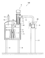
- a cryostat 100 includes a helium tank (refrigerant tank) 2 that stores liquid helium, which is a liquid refrigerant, and a refrigerator 5 provided above the helium tank 2. And a cylindrical member 15 that forms a recondensing chamber 8 that communicates with the helium tank 2, and a gas phase volume changing means 20 connected to the recondensing chamber 8.
- the cryostat 100 of the present embodiment is used for an NMR apparatus, but is not limited thereto, and may be used for an MRI apparatus, for example. Further, the refrigerant is not limited to helium.
- the helium tank 2 is provided with a gas discharge port (not shown).
- This gas discharge port is a path through which helium gas evaporates when the capacity of the refrigerator 5 is lost, and is provided at the upper end of a cylindrical member 13 described later.
- a check valve for preventing air from entering the helium tank 2 from the outside is attached to the tip of the gas discharge port.
- This check valve has a performance capable of sufficiently safely processing a large amount of helium gas generated when a superconducting magnet 1 described later is quenched. Therefore, even if the helium gas in the helium tank 2 is cooled by the refrigerator 5 and liquefied, the total amount of helium in the helium tank 2 does not change.
- the pressure in the helium tank 2 is controlled to a positive pressure slightly higher than the atmospheric pressure. Examples of the material of the helium tank 2 include aluminum and stainless steel.
- a superconducting magnet 1 is accommodated in the helium tank 2.
- the superconducting magnet 1 is formed by spirally winding a superconducting wire around a winding frame (not shown).
- the superconducting wire may be a metal-based superconducting wire or an oxide-based superconducting wire.
- a cylindrical space S (bore) extending in the vertical direction is provided at the center of the helium tank 2.
- a sample is placed in the cylindrical space S, and various analyzes and experiments are performed.
- a gas space 10 filled with helium gas is provided above the liquid helium surface in which the superconducting magnet 1 is immersed.
- the helium tank 2 is surrounded by a radiation shield 3.
- the radiation shield 3 is a shield container that is cooled by the cold heat of the helium gas so as not to let the cold heat escape. Further, the radiation shield 3 is forcibly cooled by a first cooling stage 6 described later of the refrigerator 5. Examples of the material of the radiation shield 3 include aluminum and copper.
- the vacuum container 4 is a container whose inside is maintained at a high vacuum and suppresses heat intrusion into the superconducting magnet 1 and the helium tank 2.
- a neck member 12 having a cylindrical member 13 inside is attached to the upper portion of the vacuum vessel 4.
- the cylindrical member 13 is used as a passage for inserting a current lead (not shown) or a replenishment passage for liquid helium into the helium tank 2.
- the vacuum vessel 4 is supported on the floor by a plurality of stands 9. Examples of the material of the vacuum vessel 4 include aluminum and stainless steel.
- the refrigerator 5 is for reliquefaction (recondensation) of liquid helium evaporated in the helium tank 2, and a pulse tube refrigerator is used in this embodiment.
- a first cooling stage 6 (1st stage) is provided in the middle of the refrigerator 5 in the vertical direction, and a second cooling stage 7 (2nd stage) is provided at the lower end of the refrigerator 5.
- Each of the first cooling stage 6 and the second cooling stage 7 has a flange shape, and is cooled by the refrigerator 5 to, for example, about 40K and about 4K, respectively.
- the material of the first cooling stage 6 and the second cooling stage 7 is mainly copper or a copper alloy.
- the refrigerator 5 is not limited to the pulse tube refrigerator, and may be a GM refrigerator, a Stirling refrigerator, or the like.
- the cylindrical member 15 accommodates the lower part including the second cooling stage 7 in the refrigerator 5.
- a tubular member 16 is further disposed outside the tubular member 15.
- the internal space of the tubular member 15 is a recondensing chamber 8, and the recondensing chamber 8 and the helium tank 2 are communicated with each other by a tubular communicating member 14 having a smaller diameter than the tubular member 15.
- the gas phase volume changing means 20 is placed on a stand 17 erected on the floor, and is connected to the recondensing chamber 8 with a flexible tube 11 made of stainless steel. It communicates with the phase space 10.
- the gas phase volume changing means 20 may be directly communicated with the gas phase space 10 without going through the recondensing chamber 8.
- the gas phase volume changing means 20 changes the gas phase volume of the gas phase space 10 so as to cancel the pressure fluctuation in the helium tank 2.
- the gas phase volume variation means 20 is a variation device 21 that can vary the gas phase volume of the gas phase space 10.
- a differential pressure gauge (pressure measuring means) 29 (see FIG. 3) for measuring the pressure in the gas phase space 10 or the recondensing chamber 8.
- the variable device 21 communicates with the recondensing chamber 8 through the flexible tube 11, and includes a ball screw 23 including a stainless bellows container 22 having a variable volume, a screw shaft 23a, and a nut 23b screwed to the screw shaft 23a.
- the differential pressure gauge 29 of the present embodiment is provided in the vicinity of the upper end of the cylindrical member 13 (see FIG. 1) so as to measure the pressure in the gas phase space 10. The differential pressure gauge 29 may measure the pressure inside the recondensing chamber 8.
- the side wall 22 b of the bellows container 22 has a bellows structure, and the lower wall 22 c of the bellows container 22 is fixed to the gantry 17.
- an opening is provided in the center of the upper wall 22a of the bellows container 22, and the flexible tube 11 is connected to the opening, so that the bellows container 22 is filled with helium gas.
- the gas phase volume of the gas phase space 10 varies through the recondensing chamber 8 communicating with the bellows vessel 22 by increasing or decreasing the gas phase volume of the bellows vessel 22.
- the changing device 21 is not limited to a configuration that moves linearly by the ball screw 23, and may be a configuration that makes a circular motion by a lever or the like.
- the gas phase volume changing means 20 has a driving means 26 for driving the changing apparatus 21.
- the drive means 26 includes an amplifier 27 that amplifies the measurement signal measured by the differential pressure gauge 29 and a stepping motor drive circuit 28 that drives the stepping motor 24.
- the amplifier 27 is provided with a volume for adjusting the amplification factor.
- the stepping motor drive circuit 28 treats the output signal of the amplifier 27 as a phase signal, and drives the stepping motor 24 so that the rotation of the stepping motor 24 becomes a rotation angle according to the output waveform of the amplifier 27.
- another type of motor such as a DC motor may be used instead of the stepping motor 24.
- the output signal of the stepping motor drive circuit 28 may be analogized.
- the driving means 26 may be configured as shown in FIG. That is, the measurement signal measured by the differential pressure gauge 29 is amplified by the amplifier 27, and is amplified by the current amplifier 162 and output to the DC motor 163. The rotation of the DC motor 163 is measured by the rotary encoder 164, and the pulses from the rotary encoder 164 are counted by the counter 165. The obtained count value is converted into an analog signal by a D / A converter 166, and a difference is taken by an adder (subtractor) 161 so that negative feedback is obtained.
- the gas phase volume changing means 20 changes the gas phase volume of the gas phase space 10 so as to cancel the pressure fluctuation in the helium tank 2.
- the pressure fluctuation in the helium tank 2 is caused by the liquefaction cycle of the refrigerator 5. That is, when cold is generated by the liquefaction cycle, a certain amount of helium gas is condensed and the amount of gas phase is reduced, so that the pressure in the helium tank 2 is reduced, but no cold is generated by the liquefaction cycle.
- the pressure in the helium tank 2 rises as the liquid helium vaporizes and the amount of gas phase increases. Then, the pressure in the helium tank 2 is continuously changed periodically by repeating these two state changes.
- the gas phase volume variation means 20 reduces the volume of the bellows container 22 so that the pressure in the helium tank 2 increases when the pressure in the helium tank 2 decreases due to the decrease in the amount of gas phase.
- the gas phase volume of the gas phase space 10 is reduced.
- the gas phase volume changing means 20 increases the volume of the bellows container 22 so that the pressure in the helium tank 2 decreases when the pressure in the helium tank 2 increases due to an increase in the amount of gas phase.
- the gas phase volume of the gas phase space 10 is increased. In this way, by changing the gas phase volume of the gas phase space 10, the pressure fluctuation in the helium tank 2 is canceled out. Thereby, the pressure fluctuation originating in the refrigerator 5 can be reduced.
- the driving means 26 drives the fluctuation device 21 so that a pressure having a value opposite to the measured value of the differential pressure gauge 29 is generated in the helium tank 2. That is, the measurement value of the differential pressure gauge 29 is fed back, and the gas phase volume of the gas phase space 10 is changed so that the measurement value of the differential pressure gauge 29 becomes zero.
- the pressure fluctuation in the helium tank 2 can be preferably canceled out.
- the gas phase volume changing means 20 communicating with the gas phase space 10 above the liquid level of the liquid helium in the helium tank 2 includes the inside of the helium tank 2.
- the gas phase volume of the gas phase space 10 is changed so as to cancel the pressure fluctuation. Specifically, the gas phase volume of the gas phase space 10 is reduced so that the pressure in the helium tank 2 increases when the pressure in the helium tank 2 decreases due to a decrease in the amount of gas phase.
- the gas phase volume of the gas phase space 10 is increased so that the pressure in the helium tank 2 decreases. In this way, by changing the gas phase volume of the gas phase space 10, the pressure fluctuation in the helium tank 2 is canceled out. Thereby, the pressure fluctuation originating in the refrigerator 5 can be reduced.
- the gas phase volume changing means 20 is communicated with the gas phase space 10 through the recondensing chamber 8.
- the pressure variation caused by the liquefaction cycle of the refrigerator 5 can be suitably canceled.
- the gas phase volume of the gas phase space 10 can be varied so that a pressure in the helium tank 2 is generated in a phase opposite to the measured value of the differential pressure gauge 29 that measures the pressure of the gas phase space 10.
- the variable device 21 is driven. That is, the measurement value of the differential pressure gauge 29 is fed back, and the gas phase volume of the gas phase space 10 is changed so that the measurement value of the differential pressure gauge 29 becomes zero.
- the pressure fluctuation in the helium tank 2 can be preferably canceled out.
- the noise that appears in the NMR signal can be reduced by reducing the vibration derived from the refrigerator 5.
- cryostat 200 (Configuration of gas phase volume variation means) Next, a cryostat 200 according to the second embodiment of the present invention will be described. In addition, about the same component as the component mentioned above, the same reference number is attached
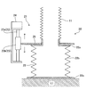
- the cryostat 200 of the present embodiment is different from the cryostat 100 of the first embodiment in that the gas phase volume variation means 30 provided in the cryostat 200 is as shown in FIG. 7 which is an enlarged sectional view of the main part A of FIG.
- the variation device 31 includes a so-called voice coil motor.
- the gas phase volume changing means 30 communicates with the gas phase space 10 via the recondensing chamber 8, and the variable device 31 capable of changing the gas phase volume of the gas phase space 10 and the first embodiment. And a similar differential pressure gauge 29 (see FIG. 8).
- the fluctuation device 31 communicates with the recondensing chamber 8 through the flexible tube 11 and is erected on the permanent magnet 33 fixed on the pedestal 17 and the permanent magnet 33 fixed on the stand 17. And a coil 35 wound around the guide 34 and capable of moving up and down.
- the gas phase volume changing means 30 may be directly communicated with the gas phase space 10 without going through the recondensing chamber 8.
- the lower wall of the container 32 is a stainless steel diaphragm 32b.
- an opening is provided in the center of the upper wall 32a of the container 32, and the flexible tube 11 is connected to the opening so that the container 32 is filled with helium gas.
- the upper end of the coil 35 is fixed to the diaphragm 32b.
- the diaphragm 32b is not limited to stainless steel, and may be made of rubber or silicon. Here, it is preferable that the diaphragm 32b has a strength that does not rupture at the time of quenching. When a soft member is used as the diaphragm 32b, it is desirable to provide a grid-like backup member to prepare for an unexpected increase in internal pressure.
- the permanent magnet 33 is preferably one that does not emit a magnetic field to the outside as much as possible, or one that is sufficiently magnetically shielded. Further, the diaphragm 32b may be changed to a thin film, and the permanent magnet 33 and the coil 35 may be changed to a speaker.
- the volume of the container 32 is reduced by pushing the diaphragm 32b upward.
- the volume of the container 32 is increased by lowering the diaphragm 32b downward. In this manner, the gas phase volume of the gas phase space 10 varies via the recondensing chamber 8 communicating with the container 32 by increasing or decreasing the gas phase volume of the container 32.
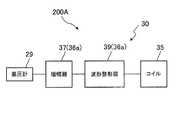
- the gas phase volume changing means 30 has a driving means 36 for driving the changing device 31.
- the driving means 36 includes an amplifier 37 that amplifies the measurement signal measured by the differential pressure gauge 29 and a current amplifier 38 that amplifies the voltage signal obtained by the amplifier 37 and outputs the current to the coil 35.
- the gas phase volume changing means 30 changes the gas phase volume of the gas phase space 10 so as to cancel the pressure fluctuation in the helium tank 2. Specifically, by reducing the volume of the container 32 so that the pressure in the helium tank 2 increases when the pressure in the helium tank 2 decreases due to a decrease in the amount of gas phase, the gas phase space is reduced. Reduce the gas phase volume of 10. On the other hand, by increasing the volume of the container 32 so that the pressure in the helium tank 2 decreases when the pressure in the helium tank 2 increases due to an increase in the amount of gas phase, the gas in the gas phase space 10 is increased. Increase the phase volume. In this way, by changing the gas phase volume of the gas phase space 10, the pressure fluctuation in the helium tank 2 is canceled out. Thereby, the pressure fluctuation originating in the refrigerator 5 can be reduced.
- the driving means 36 drives the fluctuation device 31 so as to generate a pressure in the helium tank 2 having a value opposite to the measured value of the differential pressure gauge 29. That is, the measurement value of the differential pressure gauge 29 is fed back, and the gas phase volume of the gas phase space 10 is changed so that the measurement value of the differential pressure gauge 29 becomes zero.
- the coil 35 moves so as to approach the permanent magnet 33. If the measured value of the differential pressure gauge 29 is positive and the pressure is high, the input and output of the amplifier 37 are as follows. And non-inverted (input is positive and output is positive).
- the amplifier 37 may be inverted (negative output when the input is positive) and out of phase.
- the pressure of the opposite phase value means that when the pressure measured by the differential pressure gauge 29 is high, the fluctuation device 31 is driven in a direction in which the pressure decreases. In this way, the pressure of the opposite phase value is realized by driving the fluctuation device 31 in the direction to cancel the pressure fluctuation by the driving means 36 or by inverting (negative output when the input is positive) by the amplifier 37. It can be configured with a simple analog circuit. In order to improve the control characteristics, it is also preferable in some cases to add compensation to the drive means 36 in consideration of an integral element and a differential element as in PID control.
- the gas phase volume changing means 30 may have a driving means 36a instead of the driving means 36.
- the driving means 36 a includes a waveform shaper 39 instead of the current amplifier 38.
- the waveform shaper 39 can be provided with a phase adjustment circuit that delays the output for a certain period of time, or a time lag so as not to react for a certain period of time.
- the driving unit 36a drives the fluctuation device 31 so that the pressure having a value opposite to the measured value of the differential pressure gauge 29 is generated in the helium tank 2 with a delay of a predetermined time.
- the fluctuation device 31 is driven so as to generate pressure in the helium tank 2 that is delayed in phase by about 30 ° with respect to the value of the reverse phase. Thereby, the pressure fluctuation in the helium tank 2 can be preferably canceled.
- the circuit for delaying the phase is not limited to a normal circuit configuration, digital processing by a microcomputer or the like is rather simpler.
- the driving means 36a drives the fluctuation device 31 so that the pressure of the measured value of the differential pressure gauge 29 is delayed within a predetermined time and generated in the helium tank 2.
- the reason why these phase adjustments are effective is that the change in the pressure in the helium tank 2 is delayed due to the location, and the pressure in the main part is delayed from the signal of the differential pressure gauge 29. . Further, depending on the arrangement of the differential pressure gauge 29, this relationship may be reversed.
- the pressure of the measured value of the differential pressure gauge 29 for measuring the pressure in the gas phase space 10 or the recondensing chamber 8 or a phase opposite to the measured value is driven so that the pressure of the value is delayed for a predetermined time and generated in the helium tank 2. Rather than driving the fluctuation device 31 so as to generate a pressure in the helium tank 2 having a value opposite in phase to the measurement value of the differential pressure gauge 29, the pressure in the measurement value or a pressure in the opposite phase to the measurement value.
- the fluctuation in pressure can be further reduced by driving the fluctuation device 31 so as to delay the pressure in the helium tank 2 by a predetermined time.
- the pressure fluctuation in the helium tank 2 can be preferably canceled out.
- cryostat 300 (Configuration of gas phase volume variation means) Next, a cryostat 300 according to the third embodiment of the present invention will be described. In addition, about the same component as the component mentioned above, the same reference number is attached
- the cryostat 300 of the present embodiment is different from the cryostat 100 of the first embodiment in that the gas phase volume variation means 40 provided in the cryostat 300 is a refrigeration instead of the differential pressure gauge 29 as shown in FIG. This is a point having a thermometer (temperature measuring means) 45 for measuring the temperature of the machine 5.
- thermometer 45 is attached (not shown) to the second cooling stage 7 (see FIG. 1) of the refrigerator 5 and measures the temperature of the second cooling stage 7.
- the gas phase volume changing means 40 has a driving means 41 for driving the changing device 21 (see FIG. 2).
- This drive means 41 includes an amplifier 42 that amplifies the measurement signal measured by the thermometer 45, a waveform shaper 43 that shapes the voltage signal obtained by the amplifier 42, and an output waveform shaped by the waveform shaper 43. And a stepping motor drive circuit 44 that drives the stepping motor 24.
- the driving means 41 drives the fluctuation device 21 with a waveform having a phase opposite to that of the temperature fluctuation measured by the thermometer 45.
- the temperature fluctuation of the refrigerator 5 measured by the thermometer 45 is caused by the liquefaction cycle of the refrigerator 5 as well as the pressure fluctuation in the helium tank 2. Therefore, the temperature fluctuation waveform of the refrigerator 5 is very similar to the pressure fluctuation waveform in the helium tank 2. Therefore, by varying the gas phase volume of the gas phase space 10 in a phase opposite to the waveform of the temperature variation measured by the thermometer 45, the pressure variation in the helium tank 2 can be preferably canceled out.
- the waveform of the temperature fluctuation of the refrigerator 5 is very similar to the waveform of the pressure fluctuation in the helium tank 2, but the temperature fluctuation is transmitted by metal while the temperature change of the refrigerator 5 is transmitted.
- the pressure fluctuation itself occurs with a delay or is transmitted through helium gas. For this reason, the pressure fluctuation is usually delayed from the temperature fluctuation. Therefore, when pressure is controlled using temperature fluctuations, the waveform of the temperature fluctuation measured by the thermometer 45 is inverted and reversed to the opposite phase, and then an appropriate amount of phase adjustment (usually phase delay) is added. Further, the pressure fluctuation in the helium tank 2 can be canceled more suitably.
- the waveform of the temperature fluctuation measured by the thermometer 45 that measures the temperature of the refrigerator 5 is a waveform opposite in phase to the gas phase in the gas phase space 10.
- the changing device 21 capable of changing the volume is driven.
- the temperature fluctuation of the refrigerator 5 measured by the thermometer 45 is caused by the liquefaction cycle of the refrigerator 5 as well as the pressure fluctuation in the helium tank 2. Therefore, the temperature fluctuation waveform of the refrigerator 5 is very similar to the pressure fluctuation waveform in the helium tank 2. Therefore, by varying the gas phase volume of the gas phase space 10 in a phase opposite to the waveform of the temperature variation measured by the thermometer 45, the pressure variation in the helium tank 2 can be preferably canceled out.
- the drive unit 41 drives the fluctuation device 21 with a waveform whose phase is adjusted with respect to the temperature fluctuation waveform measured by the thermometer 45.
- the waveform of the temperature fluctuation of the refrigerator 5 is very similar to the waveform of the pressure fluctuation in the helium tank 2, but the temperature fluctuation is transmitted by a metal while the temperature fluctuation is a pressure fluctuation.
- the fluctuation itself is delayed or transmitted via helium gas. For this reason, the pressure fluctuation is usually delayed from the temperature fluctuation. Therefore, when the pressure is controlled using the temperature fluctuation, it may be preferable to adjust the phase so as to be delayed by 60 ° with respect to the temperature fluctuation, for example.
- the pressure fluctuation is ideally zero, but if the pressure is controlled using temperature fluctuation, the pressure fluctuation is ideally zero as well.
- temperature fluctuations usually do not change. Therefore, in the case where the pressure is controlled by temperature fluctuation, the instability of taking the delay into the feedback system does not occur even if the phase is largely shifted. For this reason, characteristics can be improved by optimal phase adjustment, but since there is no trade-off relationship that the delay in information for adjusting the phase makes control unstable, optimal phase adjustment can be performed more freely and without restrictions. It is.
- the phase of the gas phase space 10 is adjusted with the waveform adjusted in phase with respect to the waveform of the temperature fluctuation measured by the thermometer 45 that measures the temperature of the refrigerator 5.
- the fluctuation device 21 capable of changing the phase volume is driven.
- the waveform of the temperature fluctuation of the refrigerator 5 is very similar to the waveform of the pressure fluctuation in the helium tank 2, but usually the pressure fluctuation is often delayed from the temperature fluctuation. Therefore, by driving the fluctuation device 21 with a waveform whose phase is adjusted to be delayed by, for example, 60 ° with respect to the waveform of the temperature fluctuation, the pressure fluctuation in the helium tank 2 can be preferably canceled out.
- cryostat 400 (Configuration of gas phase volume variation means)
- the cryostat 400 of the present embodiment is different from the cryostat 100 of the first embodiment in that the inside of the helium tank 2 is generated using the phase of the pressure fluctuation measured by the differential pressure gauge 29 as shown in FIG.
- the waveform of the pressure fluctuation is a driving waveform having an approximately opposite phase and is a point for driving the fluctuation device 21 (see FIG. 2).
- the pressure fluctuation in the helium tank 2 is one of the fluctuations caused by the liquefaction cycle of the refrigerator 5, and the period of such fluctuation is the same in principle. Therefore, in order to cancel the pressure fluctuation in the helium tank 2, the fluctuation device 21 is driven by the driving waveform generated using the phase of fluctuation generated by the liquefaction cycle of the refrigerator 5, and the gas phase volume of the gas phase space 10 is reduced. Just change it.
- the period of the drive waveform can be obtained.
- the phase of the drive waveform can be substantially reversed from the pressure fluctuation waveform in the helium tank 2. it can. Since the pressure fluctuation in the helium tank 2 measured by the differential pressure gauge 29 is one of the fluctuations caused by the liquefaction cycle of the refrigerator 5, the drive waveform is obtained by using the phase of the pressure fluctuation measured by the differential pressure gauge 29. Can be suitably generated.
- the drive waveform is generated by separately setting the waveform and amplitude using the phase of fluctuation caused by the liquefaction cycle of the refrigerator 5, and the waveform of fluctuation caused by the liquefaction cycle of the refrigerator 5 is generated.
- the drive waveform to be generated is basically a sine curve, but it may be better to modify it slightly. Therefore, for example, the drive waveform may be a waveform obtained by mixing a sine curve and a triangular wave by 50%. In addition, by sine curve rising earlier and slowing down to zero amplitude, the sine curve deformed so that the peak remains at 80 ° and 260 ° with zero amplitude at 0 ° and 180 °, etc.
- a waveform suitable for suppressing pressure fluctuations may be used. If one period is stored in the memory using a microcomputer, various arbitrary waveforms can be used.
- the pressure fluctuation in the helium tank 2 can be more suitably suppressed by adjusting the phase by about 30 ° with respect to the reverse phase of the pressure fluctuation measured by the differential pressure gauge 29.
- Select the optimal phase at the center As described above, the phase of the drive waveform generated in the direction that cancels out the pressure fluctuation is referred to as an anti-phase, whereas the phase that is optimally corrected centering on the anti-phase is referred to as an approximately anti-phase.
- the characteristic change due to the amplitude is large, so it is necessary to select an appropriate value.
- the period of the pressure fluctuation in the helium tank 2 is approximately the same as the period of the liquefaction cycle of the refrigerator 5 in principle and is about 1.2 Hz. Therefore, the cycle of the liquefaction cycle of the refrigerator 5 may be used as the cycle of the drive waveform.
- the gas phase volume variation means 50 included in the cryostat 400 of this embodiment includes a waveform generation means 51 that generates a drive waveform, and a stepping motor drive circuit (drive means) that drives the variation device 21 with the drive waveform generated by the waveform generation means 51. 52).
- the waveform generation means 51 uses an amplifier 53 that amplifies the measurement signal measured by the differential pressure gauge 29, a phase detector 54 that detects a phase from the signal amplified by the amplifier 53, and a phase detected by the phase detector 54. It has a waveform generator 55 that generates a drive waveform (sine curve, triangular wave, etc.) substantially in reverse phase to the waveform of pressure fluctuation in the helium tank 2.
- the waveform generator 55 is connected to a phase correction amount input device 56 for inputting a phase correction amount and an amplitude amount input device 57 for inputting an amplitude amount, and the phase correction amount and the amplitude amount are set from the outside. Has been made possible.
- the phase correction amount input device 56 and the amplitude amount input device 57 may be omitted with the phase correction amount and the amplitude amount as fixed values.
- the stepping motor drive circuit 52 drives the changing device 21 with the drive waveform generated by the waveform generating means 51 to change the gas phase volume of the gas phase space 10. Thereby, the pressure fluctuation in the helium tank 2 can be preferably canceled.
- the pressure fluctuation is caused by delaying the phase of the generated driving waveform by about 30 ° rather than driving the fluctuation device 21 using the driving waveform generated by using the phase of the pressure fluctuation measured by the differential pressure gauge 29 as it is. May be further reduced.
- the phase of the drive waveform may be delayed using the phase correction amount input device 56.
- the drive waveform to be generated is basically a sine curve, but it may be better to modify it slightly, and it is necessary to select an appropriate value because the characteristic change due to amplitude is large. is there.
- the driving is performed in a phase approximately opposite to the waveform of the pressure fluctuation in the helium tank 2 generated using the phase of fluctuation caused by the liquefaction cycle of the refrigerator 5.
- variation apparatus 21 which can fluctuate the gaseous-phase volume of the gaseous-phase space 10 with a waveform is driven.
- the pressure fluctuation in the helium tank 2 is one of the fluctuations caused by the liquefaction cycle of the refrigerator 5, and the period of such fluctuation is the same in principle.
- the fluctuation device 21 is driven by the driving waveform generated using the phase of fluctuation generated by the liquefaction cycle of the refrigerator 5, and the gas phase volume of the gas phase space 10 is reduced. Just change it.
- the phases of fluctuation caused by the liquefaction cycle of the refrigerator 5 for example, if two phases having an amplitude of 0 are used, the period of the drive waveform can be obtained.
- the phase of the drive waveform is reversed with respect to the phase of the fluctuation caused by the liquefaction cycle of the refrigerator 5, the phase of the drive waveform can be substantially reversed from the pressure fluctuation waveform in the helium tank 2. it can.
- the pressure fluctuation in the helium tank 2 can be preferably canceled out. Furthermore, if the phase of the drive waveform is slightly adjusted from the reverse phase, an appropriate waveform is selected, or the amplitude is set to an appropriate value, the pressure fluctuation in the two helium tanks can be canceled more suitably.
- a drive waveform is generated using the phase of the pressure fluctuation measured by the differential pressure gauge 29 that measures the pressure in the gas phase space 10 or the recondensing chamber 8 as the phase of fluctuation caused by the liquefaction cycle of the refrigerator 5.
- the pressure fluctuation in the helium tank 2 measured by the differential pressure gauge 29 is one of fluctuations caused by the liquefaction cycle of the refrigerator 5. Therefore, by using the pressure fluctuation phase measured by the differential pressure gauge 29, the drive waveform can be suitably generated.
- cryostat 500 (Configuration of gas phase volume variation means) Next, a cryostat 500 according to a fifth embodiment of the present invention will be described. In addition, about the same component as the component mentioned above, the same reference number is attached
- the cryostat 500 of the present embodiment is different from the cryostat 400 of the fourth embodiment in that the gas phase volume variation means 60 included in the cryostat 500 is a refrigeration instead of the differential pressure gauge 29 as shown in FIG.
- a thermometer (temperature measuring means) 46 for measuring the temperature of the machine 5 is provided, and a drive waveform is generated using the phase of temperature fluctuation measured by the thermometer 46.
- thermometer 46 is attached (not shown) to the second cooling stage 7 (see FIG. 1) of the refrigerator 5 and measures the temperature of the second cooling stage 7.
- the temperature fluctuation of the refrigerator 5 measured by the thermometer 46 is one of fluctuations caused by the liquefaction cycle of the refrigerator 5. Therefore, by using the phase of the temperature fluctuation measured by the thermometer 46, the drive waveform can be suitably generated.
- the gas phase volume variation means 60 included in the cryostat 500 of this embodiment includes a waveform generation means 61 that generates a drive waveform, and a stepping motor that drives the fluctuation device 21 (see FIG. 2) with the drive waveform generated by the waveform generation means 61.
- the waveform generation means 61 uses an amplifier 63 that amplifies the measurement signal measured by the thermometer 46, a phase detector 64 that detects a phase from the signal amplified by the amplifier 63, and a phase detected by the phase detector 64.
- a waveform generator 65 that generates a drive waveform (sine curve, triangular wave, etc.) that is substantially in reverse phase to the waveform of the pressure fluctuation in the helium tank 2 is provided.
- the waveform generator 65 is connected to a phase correction amount input device 66 for inputting a phase correction amount and an amplitude amount input device 67 for inputting an amplitude amount, and the phase correction amount and the amplitude amount are set from the outside. Has been made possible.
- the phase correction amount input device 66 and the amplitude amount input device 67 may be omitted with the phase correction amount and the amplitude amount as fixed values.
- the stepping motor drive circuit 62 drives the changing device 21 with the drive waveform generated by the waveform generating means 61 to change the gas phase volume of the gas phase space 10. Thereby, the pressure fluctuation in the helium tank 2 can be preferably canceled.
- the phase of the temperature variation is delayed by about 10 ° with respect to the liquefaction cycle, and the phase of the pressure variation is often delayed by about 50 ° with respect to the temperature variation. Therefore, rather than using the drive waveform generated using the phase of the temperature fluctuation measured by the thermometer 46 as it is and driving the fluctuation device 21, the pressure fluctuation is more delayed by the phase of the generated drive waveform by about 50 °. May be further reduced. In such a case, the phase of the drive waveform may be delayed using the phase correction amount input device 66.
- the drive waveform to be generated is basically a sine curve, but it may be better to modify it slightly, and it is necessary to select an appropriate value because the characteristic change due to amplitude is large. is there.
- the phase of temperature fluctuation measured by the thermometer 46 that measures the temperature of the refrigerator 5 is used as the phase of fluctuation caused by the liquefaction cycle of the refrigerator 5. Generate a drive waveform.
- the temperature fluctuation of the refrigerator 5 measured by the thermometer 46 is one of fluctuations caused by the liquefaction cycle of the refrigerator 5. Therefore, by using the phase of the temperature fluctuation measured by the thermometer 46, the drive waveform can be suitably generated. Further, even if the pressure fluctuation in the helium tank 2 is reduced or almost eliminated as a result of canceling out the pressure fluctuation in the helium tank 2, the temperature fluctuation of the refrigerator 5 hardly changes.
- cryostat 600 (Configuration of gas phase volume variation means) Next, a cryostat 600 according to the sixth embodiment of the present invention will be described. In addition, about the same component as the component mentioned above, the same reference number is attached
- the cryostat 600 of the present embodiment is different from the cryostat 400 of the fourth embodiment in that the gas phase volume variation means 70 included in the cryostat 600 is a refrigeration instead of the differential pressure gauge 29 as shown in FIG.
- a microphone (sound collecting means) 47 for picking up sound generated by the machine 5 is provided, and a drive waveform is generated using the phase of the change pattern of the sound picked up by the microphone 47.
- the microphone 47 is attached to the side surface of the refrigerator 5 (see FIG. 1) (not shown).
- the refrigeration cycle of the refrigerator 5 is about 1.2 Hz, but the sound emitted by the refrigerator 5 is several kHz.
- the sound from the refrigerator 5 picked up by the microphone 47 is one of the fluctuations caused by the liquefaction cycle of the refrigerator 5.
- the refrigerator 5 makes a sound “spa, spa”. Since the tone color (frequency) differs between “shu” and “pa”, it can be changed to a voltage by the F / V converter 75 described later.
- One change of the sound “spa” is about 1.2 Hz, which is the same as the refrigeration cycle. Therefore, by using the phase of the sound change (tone color change) pattern picked up by the microphone 47, the drive waveform can be suitably generated.
- the gas phase volume variation means 70 included in the cryostat 600 of this embodiment includes a waveform generation means 71 that generates a drive waveform, and a stepping motor that drives the variation device 21 (see FIG. 2) with the drive waveform generated by the waveform generation means 71.
- the waveform generation means 71 includes a filter 73 that extracts sound in a necessary frequency band from the sound picked up by the microphone 47, an amplifier 74 that amplifies the sound extracted by the filter 73, and a frequency that changes to a voltage, which is about 1 as in the refrigeration cycle. And an F / V converter 75 that converts the signal to a signal with a period of 2 Hz (a signal that indicates the period of timbre change).
- the waveform generation means 71 uses the phase detector 76 that detects the phase from the output signal of the F / V converter 75, and the waveform of the pressure fluctuation in the helium tank 2 using the phase detected by the phase detector 76. And a waveform generator 77 that generates a drive waveform (such as a sine curve or a triangular wave) having a substantially reverse phase.
- a drive waveform such as a sine curve or a triangular wave
- the waveform generator 77 is connected to a phase correction amount input device 78 for inputting a phase correction amount and an amplitude amount input device 79 for inputting an amplitude amount, and the phase correction amount and the amplitude amount are set from the outside.
- the phase correction amount input device 78 and the amplitude amount input device 79 may be omitted with the phase correction amount and the amplitude amount as fixed values.
- the stepping motor drive circuit 72 drives the changing device 21 with the drive waveform generated by the waveform generating means 71 to change the gas phase volume of the gas phase space 10. Thereby, the pressure fluctuation in the helium tank 2 can be preferably canceled.
- a vibration sensor (vibration measuring means) that measures the vibration of the refrigerator 5 is attached to the side surface of the refrigerator 5, and the vibration change pattern measured by the vibration sensor is measured.
- the drive waveform may be generated using the phase.
- the vibration of the refrigerator 5 measured by the vibration sensor is one of fluctuations caused by the liquefaction cycle of the refrigerator 5. Therefore, the drive waveform can be suitably generated by using the phase of the vibration change pattern measured by the vibration sensor.
- the change pattern of the sound and vibration from the refrigerator 5 generated by the liquefaction cycle of the refrigerator 5 is hardly delayed in phase with respect to the liquefaction cycle.
- the pressure fluctuation is delayed by about 60 ° with respect to the sound or vibration generated by the refrigerator 5. Therefore, the phase of the generated drive waveform is set to 60 ° rather than driving the fluctuation device 21 using the drive waveform generated using the phase of the vibration change pattern measured by the sound picked up by the microphone 47 or the vibration sensor.
- the pressure fluctuation can be further reduced by delaying the delay.
- the phase of the drive waveform may be delayed using the phase correction amount input device 78.
- the drive waveform to be generated is basically a sine curve, but it may be better to modify it slightly, and it is necessary to select an appropriate value because the characteristic change due to amplitude is large. is there.
- the phase of the change pattern of the sound picked up by the microphone 47 that picks up the sound emitted from the refrigerator 5 is used as the phase of fluctuation caused by the liquefaction cycle of the refrigerator 5.
- the sound from the refrigerator 5 picked up by the microphone 47 is one of fluctuations caused by the liquefaction cycle of the refrigerator 5. Therefore, by using the phase of the change pattern of the sound picked up by the microphone 47, the drive waveform can be suitably generated.
- the pressure fluctuation in the helium tank 2 can be preferably canceled out.
- the phase of the drive waveform is slightly adjusted from the reverse phase, an appropriate waveform is selected, or the amplitude is set to an appropriate value, the pressure fluctuation in the two helium tanks can be canceled more suitably.
- cryostat 700 (Configuration of gas phase volume variation means) Next, a cryostat 700 according to the seventh embodiment of the present invention will be described. In addition, about the same component as the component mentioned above, the same reference number is attached
- the cryostat 700 of the present embodiment is different from the cryostat 400 of the fourth embodiment in that the gas phase volume variation means 80 included in the cryostat 700 is a refrigeration instead of the differential pressure gauge 29 as shown in FIG.
- the pressure gauge 48 is provided inside the refrigerator 5 (see FIG. 1) (not shown).
- the position where the pressure gauge 48 is provided is preferably on the downstream side of the rotary valve of the refrigerator 5 from the viewpoint of ease of signal extraction.
- the pressure gauge 48 is provided in the vicinity of the high-pressure gas inlet into which the high-pressure side helium gas flows. Is measured, the pressure change immediately after switching by the rotary valve can be captured.
- the pressure fluctuation of the refrigerant supplied into the refrigerator 5 measured by the pressure gauge 48 is one of fluctuations caused by the liquefaction cycle of the refrigerator 5. Therefore, a drive waveform can be suitably generated by using the phase of pressure fluctuation measured by the pressure gauge 48.
- the gas phase volume variation means 80 included in the cryostat 700 of this embodiment includes a waveform generation means 81 that generates a drive waveform, and a stepping motor that drives the fluctuation device 21 (see FIG. 2) with the drive waveform generated by the waveform generation means 81.
- the waveform generation unit 81 detects a phase from a filter 83 that extracts a signal in a necessary frequency band from a measurement signal measured by the pressure gauge 48, an amplifier 84 that amplifies the signal extracted by the filter 83, and a signal amplified by the amplifier 84.
- a waveform generator 86 that generates a driving waveform (such as a sine curve or a triangular wave) having a phase substantially opposite to the waveform of the pressure fluctuation in the helium tank 2 using the phase detected by the phase detector 85 and the phase detected by the phase detector 85. And have.
- a driving waveform such as a sine curve or a triangular wave
- the waveform generator 86 is connected to a phase correction amount input device 87 for inputting a phase correction amount and an amplitude amount input device 88 for inputting an amplitude amount, and the phase correction amount and the amplitude amount are set from the outside.
- the phase correction amount input device 87 and the amplitude amount input device 88 may be omitted with the phase correction amount and the amplitude amount as fixed values.
- the stepping motor drive circuit 82 drives the changing device 21 with the drive waveform generated by the waveform generating means 81 to change the gas phase volume of the gas phase space 10. Thereby, the pressure fluctuation in the helium tank 2 can be preferably canceled.
- the refrigerant pressure fluctuation caused by the liquefaction cycle of the refrigerator 5 is a change in the power source that drives the refrigerator 5, and has little delay in the phase with respect to the liquefaction cycle, but rather slightly ahead.
- the pressure fluctuation is often delayed by about 60 ° in phase with respect to the pressure fluctuation of the refrigerant supplied into the refrigerator 5. Therefore, rather than using the drive waveform generated using the pressure fluctuation phase measured by the pressure gauge 48 and driving the fluctuation device 21 as it is, the phase of the generated drive waveform is delayed by about 60 °. May be further reduced. In such a case, the phase of the drive waveform may be delayed using the phase correction amount input device 87.
- the drive waveform to be generated is basically a sine curve, but it may be better to modify it slightly, and it is necessary to select an appropriate value because the characteristic change due to amplitude is large. is there.
- the phase of the pressure fluctuation measured by the pressure gauge 48 that measures the pressure of the refrigerant supplied into the refrigerator 5 is generated by the liquefaction cycle of the refrigerator 5.
- a drive waveform is generated using the phase of fluctuation.
- the pressure fluctuation of the refrigerant supplied into the refrigerator 5 measured by the pressure gauge 48 is one of fluctuations caused by the liquefaction cycle of the refrigerator 5. Therefore, a drive waveform can be suitably generated by using the phase of pressure fluctuation measured by the pressure gauge 48.
- the pressure fluctuation in the helium tank 2 can be preferably canceled out.
- the phase of the drive waveform is slightly adjusted from the reverse phase, an appropriate waveform is selected, or the amplitude is set to an appropriate value, the pressure fluctuation in the two helium tanks can be canceled more suitably.
- cryostat 800 according to an eighth embodiment of the present invention will be described.
- the same reference number is attached
- the cryostat 800 of the present embodiment is different from the cryostat 400 of the fourth embodiment in that the gas phase volume variation means 90 included in the cryostat 800 is described later, instead of the differential pressure gauge 29, as shown in FIG.
- a resolver (rotation angle detection means) 49 for detecting the rotation angle of the valve motor of the refrigerator 101 is provided, and a drive waveform is generated using the rotation phase of the valve motor detected by the resolver 49.
- the refrigerator 101 provided in the cryostat 800 of the present embodiment is a gas pressure drive type that expands high-pressure helium gas (working gas) by reciprocating the displacer 122 with helium gas pressure in the cylinder 103.
- GM refrigerator Green McMahon cycle expander.
- the refrigerator 101 of the present embodiment may be a pulse tube refrigerator.
- the refrigerator 101 includes a hermetically sealed motor head 102 and a cylinder 103 having a large and small two-stage structure that is airtightly connected to the lower surface of the motor head 102 and includes an upper large-diameter portion 103a and a lower small-diameter portion 103b. And.
- a high pressure gas inlet 104 and a low pressure gas outlet 105 located below the high pressure gas inlet 104 are formed on the side surface of the motor head 102.
- the high pressure gas inlet 104 is connected to the discharge side of the compressor (not shown) via a high pressure pipe, and the low pressure gas outlet 105 is connected to the suction side of the compressor via a low pressure pipe.
- a motor chamber 106 that communicates with the high-pressure gas inlet 104, a mounting hole 107 that is located below the motor chamber 106 and communicates with the motor chamber 106, and a periphery of the mounting hole 107.
- An intermediate pressure chamber 108 formed of a substantially annular space is formed inside the motor head 102.
- valve stem 109 constituting a closing member at the upper end (base end) of the cylinder 103 is inserted and fitted in a boundary portion between the motor head 102 and the cylinder 103.
- a valve chamber 110 communicating with the high-pressure gas inlet 104 through the motor chamber 106 is formed by a space surrounded by the upper surface of the valve stem 109 and the wall surface of the mounting hole 107.
- the valve stem 109 has a first gas branch 112 having an upper half branched into a bifurcated shape, and a first gas passage 112 that allows the valve chamber 110 to communicate with the cylinder 103, and a first end through a low pressure port of a rotary valve 135 described later.
- a second gas flow path 114 that communicates with the gas flow path 112 and communicates with the low pressure gas outlet 105 at the other end via a communication path 113 formed in the motor head 102 is formed to penetrate therethrough.
- the first gas flow path 112 is always in communication with the intermediate pressure chamber 108 via the capillary tube 115.
- the second gas flow path 114 is opened at the center of the valve stem 109 on the upper surface of the valve stem 109 facing the valve chamber 110.
- the branched first gas flow path 112 is opened at a position symmetrical to the second gas flow path 114 on the upper surface of the valve stem 109 facing the valve chamber 110.
- a substantially cup-shaped slack piston 117 having a bottom wall is provided at the upper end portion of the large-diameter portion 103a of the cylinder 103 so that the inner surface of the cylinder 103 slides and guides to the lower portion of the valve stem 109. It is mated.
- the slack piston 117 defines a lower pressure chamber 129 at the lower portion of the cylinder 103 and an upper pressure chamber 120 at the upper end of the cylinder 103.
- the upper pressure chamber 120 is always in communication with the intermediate pressure chamber 108 in the motor head 102 via the orifice 121.
- the upper pressure chamber 120 is set to an intermediate pressure between the high pressure and the low pressure helium gas, and the slack piston 117 reciprocates together with the displacer 122 by the pressure difference between the upper pressure chamber 120 and the lower pressure chamber 129. It is supposed to move.
- a large-diameter central hole is formed through the center of the bottom wall of the slack piston 117, and a plurality of communication holes are formed at the peripheral corners to communicate the inside and outside of the slack piston 117.
- a displacer (replacer) 122 is fitted so as to be reciprocally movable.
- the displacer 122 is coupled to the closed cylindrical large-diameter portion 122a that slides in the substantially lower half of the large-diameter portion 103a of the cylinder 103 and the lower end of the large-diameter portion 122a so as to move together.
- a small cylindrical portion 122b having a sealed cylindrical shape.
- the space in the large-diameter portion 122 a of the displacer 122 is always in communication with the first stage expansion chamber 130 through the communication hole 123.
- a space in the large diameter portion 122a is provided with a first stage regenerator 124 made of a regenerator type heat exchanger fitted therein.
- the space in the small diameter portion 122b of the displacer 122 is always in communication with the first stage expansion chamber 130 through the communication hole 125 and with the second stage expansion chamber 131 through the communication hole 126.
- a second stage regenerator 127 similar to the first stage regenerator 124 is provided in a space in the displacer small diameter portion 122b.
- a tubular locking piece 133 is provided at the upper end of the large-diameter portion 122a of the displacer 122 so as to protrude integrally with the space in the large-diameter portion 122a communicating with the lower pressure chamber 129.
- the upper portion of the locking piece 133 passes through the center hole of the bottom wall of the slack piston 117 and extends into the slack piston 117 by a predetermined dimension.
- the upper end of the locking piece 133 is a flange-shaped locking portion that engages with the bottom wall of the slack piston 117.
- 133a is integrally formed.
- the displacer 122 When the slack piston 117 is moved downward, when the slack piston 117 is lowered by a predetermined stroke, the displacer 122 is driven by the slack piston 117 by the contact between the bottom wall bottom surface and the top surface of the displacer 122 and starts to descend. On the other hand, when the slack piston 117 is moved upward, the displacer 122 is driven by the slack piston 117 due to the engagement between the upper surface of the bottom wall and the locking portion 133a of the locking piece 133 when the slack piston 117 is lifted by a predetermined stroke. Start to rise.
- the displacer 122 is configured to move following the slack piston 117 with a predetermined stroke delay.
- a lower pressure chamber 129 serving as an expansion space in the cylinder 103 and a high pressure valve opening state for supplying high pressure helium gas to the expansion chambers 130 and 131, and a lower pressure chamber 129 are provided.
- a rotary valve 135 is provided as valve means for switching alternately to a low pressure valve open state in which helium gas is discharged from the expansion chambers 130 and 131.
- the rotary valve 135 is rotationally driven by a valve motor 139 disposed in the motor chamber 106. That is, the output shaft 139a of the valve motor 139 is engaged with the central portion of the upper surface of the rotary valve 135 so as to rotate together.
- a pair of high-pressure ports and a low-pressure port disposed at an angular interval of approximately 90 ° with respect to the high-pressure port in the rotation direction of the rotary valve 135 are formed.
- the valve chamber 110 that communicates with the high pressure gas inlet 104, that is, the high pressure gas inlet 104, and the communication passage 113 that communicates with the low pressure gas outlet 105, that is, the low pressure gas outlet 105 are
- the side pressure chamber 129, the first stage and the second stage expansion chambers 130 and 131 are alternately communicated with each other.
- a pressure difference is generated between the lower pressure chamber 129 and the upper pressure chamber 120, and the slack piston 117 and the displacer 122 are reciprocated in the cylinder 103 by this pressure difference.
- a first cooling stage 141 is provided at the distal end (lower end) of the large diameter portion 103a of the cylinder 103, and a second cooling stage 142 is provided at the distal end (lower end) of the small diameter portion 103b of the cylinder 103. Yes.
- a resolver 49 is provided in the motor chamber 106.
- An output shaft 139b of the valve motor 139 is engaged with the resolver 49 in an integrated manner.
- the output shaft 139b is integrated with an output shaft 139a that rotates the rotary valve 135.
- the resolver 49 detects the rotation angle of the valve motor 139.
- An output signal from the resolver 49 is output to the outside via a metal connector 144 provided in the motor head 102.
- normal-temperature high-pressure helium gas supplied to the valve chamber 110 via the high-pressure gas inlet 104 and the motor chamber 106 of the refrigerator 101 passes through the slack piston 117 via the high-pressure port of the rotary valve 135 and the first gas flow path 112. It is introduced into the lower lower pressure chamber 129. Further, normal-temperature high-pressure helium gas is sequentially charged from the lower pressure chamber 129 to the expansion chambers 130 and 131 through the regenerators 124 and 127 of the displacer 122 and passes through the regenerators 124 and 127. It is cooled by heat exchange.
- the slack piston 117 rises due to the pressure difference between the pressure chambers 120 and 129.
- the rising stroke of the slack piston 117 reaches a predetermined value, the upper surface of the bottom wall of the slack piston 117 and the locking portion 133a of the locking piece 133 are engaged, and the displacer 122 has a delay with respect to the pressure change.
- the slack piston 117 is pulled up. As the displacer 122 moves up, the expansion chambers 130 and 131 below the displacer 122 are further filled with high-pressure gas.
- the low pressure port of the rotary valve 135 matches the opening end of the first gas flow path 112 on the upper surface of the valve stem 109, and the rotary valve 135 opens to the low pressure side.
- the helium gas in the expansion chambers 130 and 131 below the displacer 122 is expanded by Simon.
- the first cooling stage 141 is cooled to a predetermined temperature level and the second cooling stage 142 is cooled to a temperature level lower than that of the first cooling stage 141 due to the temperature drop caused by the gas expansion.
- the helium gas that has become a low temperature in the expansion chambers 130 and 131 returns to the lower pressure chamber 129 through the regenerators 124 and 127 in the displacer 122, contrary to when the gas is introduced. By cooling 127, its temperature rises to room temperature.
- This normal temperature helium gas is discharged together with the gas in the lower pressure chamber 129 to the outside of the refrigerator 101 through the first gas flow path 112, the low pressure port of the rotary valve 135, and the communication path 113, and the low pressure gas outlet. It flows through 105 to the compressor and is sucked into it. As the gas is discharged, the gas pressure in the lower pressure chamber 129 decreases, and the slack piston 117 moves down due to the pressure difference with the upper pressure chamber 120.
- the displacer 122 After the bottom wall lower surface of the slack piston 117 contacts the upper surface of the displacer 122, the displacer 122 is pressed and lowered. By the downward movement of the displacer 122, the gas in the expansion chambers 130 and 131 is further discharged out of the refrigerator 101.
- the gas phase volume fluctuation means 90 included in the cryostat 800 of this embodiment includes a waveform generation means 91 that generates a drive waveform, and a fluctuation device 21 (see FIG. 2) using the drive waveform generated by the waveform generation means 91.
- the cycle of the pressure fluctuation in the helium tank 2 is in principle the same as the cycle of the liquefaction cycle of the refrigerator 101. Therefore, in order to cancel the pressure fluctuation in the helium tank 2, the fluctuation device 21 is driven by the driving waveform generated using the phase of the liquefaction cycle of the refrigerator 101, and the gas phase volume of the gas phase space 10 is changed. Do it.
- the phases of the liquefaction cycle of the refrigerator 101 for example, if two phases having an amplitude of 0 are used, the period of the drive waveform can be obtained.
- the phase of the drive waveform can be substantially reversed from the waveform of the pressure fluctuation in the helium tank 2. Then, by rotating the rotary valve 135 by the valve motor 139, a liquefaction cycle occurs in the refrigerator 101. Therefore, the phase of the rotation of the valve motor 139 detected by the resolver 49 is the phase of the liquefaction cycle of the refrigerator 101. Therefore, the drive waveform can be suitably generated by using the rotation phase of the valve motor 139 detected by the resolver 49.
- the resolver 49 outputs a sine curve whose phase angle is shifted by the rotation of the output shaft 139b with respect to the input sine curve and cosine curve.
- the waveform generation unit 91 converts the output signal of the resolver 49 into digital angle data, and processes the converted data so that the waveform of the pressure fluctuation in the helium tank 2 is approximately.
- a microcomputer 94 for generating a reverse-phase driving waveform (sine curve, triangular wave, etc.).
- the microcomputer 94 is connected to a phase correction amount input device 95 for inputting a phase correction amount and an amplitude amount input device 96 for inputting an amplitude amount, so that the phase correction amount and the amplitude amount can be set from the outside.
- the phase correction amount input device 95 and the amplitude amount input device 96 may be omitted with the phase correction amount and the amplitude amount as fixed values.
- the stepping motor drive circuit 92 drives the changing device 21 with the drive waveform generated by the waveform generating means 91 to change the gas phase volume of the gas phase space 10. Thereby, the pressure fluctuation in the helium tank 2 can be preferably canceled.
- the rotation of the valve motor 139 Since the liquefaction cycle is generated in the refrigerator 101 due to the rotation of the valve motor 139, the rotation of the valve motor 139 has zero phase lag with respect to the liquefaction cycle, whereas the pressure fluctuation causes the liquefaction of the refrigerator 101. In many cases, the phase is delayed by about 60 ° with respect to the cycle. Therefore, rather than using the drive waveform generated by using the phase of rotation of the valve motor 139 detected by the resolver 49 as it is to drive the fluctuation device 21, the phase of the generated drive waveform is delayed by about 60 °. In some cases, pressure fluctuations can be further reduced. In such a case, the phase of the drive waveform may be delayed using the phase correction amount input device 95. As described above, the drive waveform to be generated is basically a sine curve, but it may be better to modify it slightly, and it is necessary to select an appropriate value because the characteristic change due to amplitude is large. is there.
- a signal may be extracted by a photo interrupter 59 using a rotary encoder that measures the rotation of the valve motor 139 instead of the resolver 49.
- the rotary encoder may be an absolute type that outputs a signal once per rotation, or may be an incremental type that outputs signals (A phase and B phase) detected by two sets of photoelectric elements. .
- an incremental rotary encoder of a type in which a pulse is generated once in one rotation called Z phase is used.
- a small magnetic material, a reed switch, a limit switch, or the like may be used.
- the photo interrupter circuit 97 takes out a signal per rotation from the photo interrupter 59.
- the phase detector 98 detects the phase from the signal extracted by the photocoupler circuit 97.
- the waveform generator 99 uses the phase detected by the phase detector 98 to generate a drive waveform (such as a sine curve or a triangular wave) that is substantially opposite in phase to the pressure fluctuation waveform in the helium tank 2. It may be better to adjust the phase of the generated drive waveform, the generated drive waveform is basically a sine curve, but it may be better to modify it slightly, and the characteristic change due to the amplitude is large Therefore, it is necessary to select an appropriate value as described above.
- the phase may be detected from on / off of the drive voltage of at least one of these valves.
- the waveform of the pressure fluctuation in the helium tank 2 generated using the phase of the liquefaction cycle of the refrigerator 101 is a driving waveform that is approximately in reverse phase.
- the changing device 21 capable of changing the gas phase volume of the gas phase space 10 is driven.
- the period of pressure fluctuation in the helium tank 2 is in principle the same as the period of the liquefaction cycle of the refrigerator 101. Therefore, in order to cancel the pressure fluctuation in the helium tank 2, the fluctuation device 21 is driven by the driving waveform generated using the phase of the liquefaction cycle of the refrigerator 101, and the gas phase volume of the gas phase space 10 is changed. Do it.
- the period of the drive waveform can be obtained.
- the phase of the drive waveform is reversed with respect to the phase of the liquefaction cycle of the refrigerator 101, the phase of the drive waveform can be substantially reversed from the waveform of the pressure fluctuation in the helium tank 2.
- the pressure fluctuation in the helium tank 2 can be preferably canceled out.
- the phase of the drive waveform is slightly adjusted from the reverse phase, an appropriate waveform is selected, or the amplitude is set to an appropriate value, the pressure fluctuation in the two helium tanks can be canceled more suitably.
- a drive waveform is generated by using the rotation phase of the valve motor 139 detected by the resolver 49 that detects the rotation angle of the valve motor 139 as the phase of the liquefaction cycle of the refrigerator 101.
- the rotation phase of the valve motor 139 detected by the resolver 49 is the phase of the liquefaction cycle of the refrigerator 101. Therefore, the drive waveform can be suitably generated by using the rotation phase of the valve motor 139 detected by the resolver 49.
- the cryostat 900 of the present embodiment is different from the cryostat 800 of the eighth embodiment in that the vapor phase volume changing means 150 included in the cryostat 900 is output from a motor drive circuit 145 as shown in FIG.
- the driving waveform is generated using the phase of the driving signal of the valve motor 139.
- the phase of the drive signal of the valve motor 139 is the phase of the liquefaction cycle of the refrigerator 101. Therefore, a drive waveform can be suitably generated by using the phase of the drive signal of the valve motor 139.
- the gas phase volume variation means 150 included in the cryostat 900 of this embodiment includes a waveform generation means 151 that generates a drive waveform, and a stepping motor that drives the variation device 21 (see FIG. 2) with the drive waveform generated by the waveform generation means 151.
- the waveform generation means 151 includes a conversion circuit 153 that converts a drive signal output from the motor drive circuit 145 to the valve motor 139 into a waveform signal, a phase detector 154 that detects a phase from the converted signal, and a phase detector 154.
- a waveform generator 155 that generates a drive waveform (such as a sine curve or a triangular wave) substantially in reverse phase to the waveform of the pressure fluctuation in the helium tank 2 using the detected phase.
- the waveform generator 155 is connected to a phase correction amount input device 156 for inputting a phase correction amount and an amplitude amount input device 157 for inputting an amplitude amount, and the phase correction amount and the amplitude amount are set from the outside. Has been made possible.
- the phase correction amount input device 156 and the amplitude amount input device 157 may be omitted with the phase correction amount and the amplitude amount as fixed values.
- the stepping motor drive circuit 152 drives the changing device 21 with the drive waveform generated by the waveform generating means 151 to change the gas phase volume of the gas phase space 10. Thereby, the pressure fluctuation in the helium tank 2 can be preferably canceled.
- the drive signal of the valve motor 139 since the liquefaction cycle occurs in the refrigerator 101 due to the rotation of the valve motor 139, the drive signal of the valve motor 139 has zero phase lag with respect to the liquefaction cycle, whereas the pressure fluctuations of the refrigerator 101 In many cases, the phase is delayed by about 60 ° with respect to the liquefaction cycle. Therefore, rather than using the drive waveform generated using the phase of the drive signal of the valve motor 139 as it is and driving the fluctuation device 21, the pressure fluctuation is more delayed when the phase of the generated drive waveform is delayed by about 60 °. There are cases where it can be reduced. In such a case, the phase of the drive waveform may be delayed using the phase correction amount input device 156. As described above, the drive waveform to be generated is basically a sine curve, but it may be better to modify it slightly, and it is necessary to select an appropriate value because the characteristic change due to amplitude is large. is there.
- the drive waveform is generated using the phase of the drive signal of the valve motor 139 as the phase of the liquefaction cycle of the refrigerator 101.
- the phase of the drive signal of the valve motor 139 is the phase of the liquefaction cycle of the refrigerator 101. Therefore, a drive waveform can be suitably generated by using the phase of the drive signal of the valve motor 139.
- the pressure fluctuation in the helium tank 2 can be preferably canceled out.
- the phase of the drive waveform is slightly adjusted from the reverse phase, an appropriate waveform is selected, or the amplitude is set to an appropriate value, the pressure fluctuation in the two helium tanks can be canceled more suitably.
- the driving waveform may be generated using the phase of the driving signal of the moving coil of the helium pump as the phase of the liquefaction cycle of the refrigerator. Further, such a helium pump may be communicated with the gas phase space 10 and used instead of the fluctuation device 21 and the fluctuation device 31.
- gas phase volume of the gas phase space 10 may be changed by providing a thin plate portion on the helium tank 2 or the cylindrical member 15 and attaching a speaker and applying an acoustic effect from the speaker.
Landscapes
- Engineering & Computer Science (AREA)
- Physics & Mathematics (AREA)
- Mechanical Engineering (AREA)
- General Engineering & Computer Science (AREA)
- Condensed Matter Physics & Semiconductors (AREA)
- General Physics & Mathematics (AREA)
- Power Engineering (AREA)
- Thermal Sciences (AREA)
- Containers, Films, And Cooling For Superconductive Devices (AREA)
- Electromagnetism (AREA)
Abstract
冷凍機に由来する圧力変動を低減させることができるようにする。 ヘリウム槽2内における液体ヘリウムの液面よりも上方の気相空間10に連通する気相容積変動手段20で、ヘリウム槽2内の圧力変動を打ち消すように、気相空間10の気相容積を変動させる。
Description
本発明は、超電導マグネット等を冷却するためのクライオスタットに関する。
NMR装置等に適用される超電導マグネット装置においては、冷媒である液体ヘリウムの消費をゼロにするために、蒸発した冷媒を再凝縮する冷凍機が用いられる。しかし、冷凍機の周期的な液化サイクルは、冷媒を収容する冷媒槽内に圧力変動を発生させ、冷媒槽に微小な変位をもたらす。その結果、測定対象の磁場に擾乱が発生し、測定結果に有害なノイズが発生する。
そこで、特許文献1には、冷凍機が発生させる音響波の波長よりも直径が十分に小さい孔が多数設けられたプラグを、冷凍機の下部を収容する再凝縮室と、液体ヘリウムを収容する冷媒槽とをつなぐ通路に設けたクライオスタットアセンブリが開示されている。冷媒槽内で液体ヘリウムが蒸発することで生じたヘリウムガスは、多数の孔を通って再凝縮室に入る。再凝縮室内でヘリウムガスが再凝縮することで生じた液体ヘリウムは、多数の孔を通って冷媒槽に戻る。そして、冷凍機で発生した音響波は、多数の孔を通過する際に減衰されることとなる。
しかしながら、特許文献1のプラグには、以下のような問題点がある。即ち、冷凍機のメンテナンス時に、冷媒槽は一時的に開放される。このときに、冷媒槽内に微少な空気が混入する可能性がある。冷媒槽内に混入した空気は冷媒で冷却されて凝縮し、冷媒槽内に留まる。この凝縮した空気が、万一プラグの多数の孔を閉塞させた場合には、冷媒槽と再凝縮室との通路が遮断され、再凝縮機能に致命的な不全が生じる。
本発明の目的は、冷凍機に由来する圧力変動を低減させることが可能なクライオスタットを提供することである。
本発明におけるクライオスタットは、液体の冷媒を収容する冷媒槽と、前記冷媒槽の上方に設けられ、前記冷媒槽内で蒸発した冷媒を再凝縮させる冷凍機と、前記冷凍機の下部を収容して前記冷媒槽に連通する再凝縮室を形成する筒状部材と、前記冷媒槽内における液体の冷媒の液面よりも上方の気相空間に連通し、前記冷媒槽内の圧力変動を打ち消すように、前記気相空間の気相容積を変動させる気相容積変動手段と、を有することを特徴とする。
本発明によれば、冷媒槽内における液体の冷媒の液面よりも上方の気相空間に連通する気相容積変動手段で、冷媒槽内の圧力変動を打ち消すように、気相空間の気相容積を変動させる。ここで、冷媒槽内の圧力変動は、冷凍機の液化サイクルにより引き起こされる。即ち、液化サイクルにより寒冷が発生しているときに、冷媒が一定量凝縮して気相量が減少することで冷媒槽内の圧力が減少する一方、液化サイクルにより寒冷が発生していないときに、冷媒が気化して気相量が増加することで冷媒槽内の圧力が上昇する。そして、この2つの状態変化が繰り返されることで冷媒槽内の圧力は周期的に絶えず変化する。そこで、気相量が減少することで冷媒槽内の圧力が減少した際に、冷媒槽内の圧力が上昇するように気相空間の気相容積を小さくする一方、気相量が増加することで冷媒槽内の圧力が上昇した際に、冷媒槽内の圧力が減少するように気相空間の気相容積を大きくする。このように、気相空間の気相容積を変動させることで、冷媒槽内の圧力変動が打ち消される。これにより、冷凍機に由来する圧力変動を低減させることができる。
以下、本発明の好適な実施の形態について、図面を参照しつつ説明する。
[第1実施形態]
(クライオスタットの構成)
本発明の第1実施形態によるクライオスタット100は、図1に示すように、液体の冷媒である液体ヘリウムを収容するヘリウム槽(冷媒槽)2と、ヘリウム槽2の上方に設けられた冷凍機5と、ヘリウム槽2に連通する再凝縮室8を形成する筒状部材15と、再凝縮室8に接続された気相容積変動手段20と、を有している。なお、本実施形態のクライオスタット100は、NMR装置に用いられるものであるが、これに限定されず、例えば、MRI装置に用いられるものであってもよい。また、冷媒はヘリウムに限定されない。
(クライオスタットの構成)
本発明の第1実施形態によるクライオスタット100は、図1に示すように、液体の冷媒である液体ヘリウムを収容するヘリウム槽(冷媒槽)2と、ヘリウム槽2の上方に設けられた冷凍機5と、ヘリウム槽2に連通する再凝縮室8を形成する筒状部材15と、再凝縮室8に接続された気相容積変動手段20と、を有している。なお、本実施形態のクライオスタット100は、NMR装置に用いられるものであるが、これに限定されず、例えば、MRI装置に用いられるものであってもよい。また、冷媒はヘリウムに限定されない。
ヘリウム槽2にはガス放出口(図示せず)が設けられている。このガス放出口は、冷凍機5の能力を喪失した際にヘリウムガスが蒸発する経路であり、後述する筒部材13の上端部に設けられている。このガス放出口の先端には、外部からヘリウム槽2内への空気の混入を防止するための逆止弁が取り付けられている。この逆止弁は、後述する超電導マグネット1がクエンチした際に発生する大量のヘリウムガスを十分安全に処理できる性能を備えている。そのため、ヘリウム槽2内のヘリウムガスが冷凍機5によって冷却されて液化してもヘリウム槽2内の総ヘリウム量は変化しない。また、ヘリウム槽2内への空気の混入を防止するために、ヘリウム槽2内の圧力は、大気圧よりも僅かに高い正圧に制御されている。ヘリウム槽2の材質としては、アルミニウム、ステンレスなどが挙げられる。
ヘリウム槽2内には、超電導マグネット1が収容されている。超電導マグネット1は、超電導線材を巻枠(図示せず)に螺旋状に巻回してなるものである。超電導線材は、金属系超電導線材であってもよいし、酸化物系超電導線材であってもよい。また、ヘリウム槽2の中心部には、鉛直方向に延びる円筒空間S(ボア)が設けられている。この円筒空間Sに試料が入れられ、様々な分析・実験が行われる。ヘリウム槽2内において、超電導マグネット1が浸漬される液体ヘリウムの液面よりも上方は、ヘリウムガスで満たされた気相空間10となっている。
ヘリウム槽2は、輻射シールド3で囲まれている。この輻射シールド3は、冷熱をより逃がさないようにするための、ヘリウムガスの有する冷熱で冷却されるシールド容器である。また、輻射シールド3は、冷凍機5の後述する第1冷却ステージ6により強制冷却されている。輻射シールド3の材質としては、アルミニウム、銅などが挙げられる。
また、ヘリウム槽2および輻射シールド3は、真空容器4内に収容されている。この真空容器4は、その内部を高真空に保持され、超電導マグネット1やヘリウム槽2への熱侵入を抑制する容器である。真空容器4の上部には、内部に筒部材13を有するネック部材12が取り付けられている。筒部材13は、電流リード(図示せず)の挿入通路として用いられたり、ヘリウム槽2内への液体ヘリウムの補充通路として用いられたりする。また、真空容器4は、複数のスタンド9によって床上に支持されている。真空容器4の材質としては、アルミニウム、ステンレスなどが挙げられる。
冷凍機5は、ヘリウム槽2内で蒸発した液体ヘリウムを再液化(再凝縮)させるためのものであり、本実施形態ではパルスチューブ冷凍機が用いられている。冷凍機5の鉛直方向における中途部には第1冷却ステージ6(1stステージ)が設けられ、冷凍機5の下端部には第2冷却ステージ7(2ndステージ)が設けられている。第1冷却ステージ6および第2冷却ステージ7は、いずれもフランジ状の形態を有しており、冷凍機5により冷却されて、それぞれ、例えば約40Kおよび約4Kになる。第1冷却ステージ6および第2冷却ステージ7の材質は、主に銅や銅合金である。なお、冷凍機5は、パルスチューブ冷凍機に限定されず、GM冷凍機やスターリング冷凍機などであってもよい。
筒状部材15は、冷凍機5における第2冷却ステージ7を含む下部を収容している。この筒状部材15の外側にはさらに筒状部材16が配置されている。この筒状部材15の内部空間が再凝縮室8であり、この再凝縮室8とヘリウム槽2とは、筒状部材15よりも小径の筒状の連通部材14で連通されている。
(気相容積変動手段の構成)
気相容積変動手段20は、床上に立設された架台17上に載置されており、ステンレス製のフレキシブルチューブ11で再凝縮室8に接続されることで、再凝縮室8を介して気相空間10に連通している。なお、気相容積変動手段20は、再凝縮室8を介さずに、気相空間10に直接連通していてもよい。この気相容積変動手段20は、ヘリウム槽2内の圧力変動を打ち消すように、気相空間10の気相容積を変動させる。
気相容積変動手段20は、床上に立設された架台17上に載置されており、ステンレス製のフレキシブルチューブ11で再凝縮室8に接続されることで、再凝縮室8を介して気相空間10に連通している。なお、気相容積変動手段20は、再凝縮室8を介さずに、気相空間10に直接連通していてもよい。この気相容積変動手段20は、ヘリウム槽2内の圧力変動を打ち消すように、気相空間10の気相容積を変動させる。
具体的には、図1の要部Aの拡大断面図である図2に示すように、気相容積変動手段20は、気相空間10の気相容積を変動させることが可能な変動装置21と、気相空間10または再凝縮室8内の圧力を測定する差圧計(圧力測定手段)29(図3参照)と、を有している。変動装置21は、フレキシブルチューブ11を介して再凝縮室8に連通し、容積が可変なステンレス製の蛇腹容器22と、ねじ軸23aとこれに螺合するナット23bとを備えたボールねじ23と、ねじ軸23aを回転させるステッピングモータ24と、ナット23bに結合されて蛇腹容器22の上壁22aに固定された平板25と、を有している。なお、ステッピングモータ24は電源投入時に現在の位置が分からないので、現位置用センサ(図示せず)で原点位置を検出する手段が必要であるが、省略している。本実施形態の差圧計29は、気相空間10の圧力を測定するように、筒部材13(図1参照)の上端付近に設けられている。なお、差圧計29は、再凝縮室8内の圧力を測定するものであってもよい。
蛇腹容器22の側壁22bは蛇腹構造になっており、蛇腹容器22の下壁22cは架台17に固定されている。また、蛇腹容器22の上壁22aの中央には開口部が設けられており、この開口部にフレキシブルチューブ11が接続されることで、蛇腹容器22内はヘリウムガスで満たされている。
このような構成において、ステッピングモータ24の回転によりナット23bが下方に移動されて平板25が下方に移動されると、蛇腹容器22の上壁22aが下方に押し下げられることで、蛇腹容器22の容積が小さくなる。反対に、ステッピングモータ24の回転によりナット23bが上方に移動されて平板25が上方に移動されると、蛇腹容器22の上壁22aが上方に引き上げられることで、蛇腹容器22の容積が大きくなる。このように、蛇腹容器22の気相容積が増減されることで、蛇腹容器22に連通する再凝縮室8を介して、気相空間10の気相容積が変動する。なお、変動装置21は、ボールねじ23により直動する構成に限定されず、レバーなどにより円弧運動する構成であってもよい。
また、回路図である図3に示すように、気相容積変動手段20は、変動装置21を駆動する駆動手段26を有している。この駆動手段26は、差圧計29が測定した測定信号を増幅する増幅器27と、ステッピングモータ24を駆動させるステッピングモータ駆動回路28とを有している。なお、増幅器27には、増幅率を調整するためのボリュームが取り付けられている。ステッピングモータ駆動回路28は、増幅器27の出力信号を位相信号として扱い、ステッピングモータ24の回転が増幅器27の出力波形通りの回転角度になるようにステッピングモータ24を駆動する。なお、ステッピングモータ24の代わりにDCモータなど他のタイプのモータを用いてもよい。この場合、ステッピングモータ駆動回路28の出力信号をアナログ化すればよい。
なお、駆動手段26は、図4に示すように構成されていてもよい。即ち、差圧計29が測定した測定信号を増幅器27で増幅し、これを電流増幅器162で電流増幅してDCモータ163に出力する。DCモータ163の回転をロータリーエンコーダ164で測定して、ロータリーエンコーダ164からのパルスをカウンタ165でカウントする。得られたカウント値をD/A変換器166でアナログ化し、加算器(減算器)161でネガティブフィードバックになるように差を取る。
上述したように、気相容積変動手段20は、ヘリウム槽2内の圧力変動を打ち消すように、気相空間10の気相容積を変動させる。ここで、ヘリウム槽2内の圧力変動は、冷凍機5の液化サイクルにより引き起こされている。即ち、液化サイクルにより寒冷が発生しているときに、ヘリウムガスが一定量凝縮して気相量が減少することでヘリウム槽2内の圧力が減少する一方、液化サイクルにより寒冷が発生していないときに、液体ヘリウムが気化して気相量が増加することでヘリウム槽2内の圧力が上昇する。そして、この2つの状態変化が繰り返されることでヘリウム槽2内の圧力は周期的に絶えず変化する。
そこで、気相容積変動手段20は、気相量が減少することでヘリウム槽2内の圧力が減少した際に、ヘリウム槽2内の圧力が上昇するように、蛇腹容器22の容積を小さくすることで、気相空間10の気相容積を小さくする。一方、気相容積変動手段20は、気相量が増加することでヘリウム槽2内の圧力が上昇した際に、ヘリウム槽2内の圧力が減少するように、蛇腹容器22の容積を大きくすることで、気相空間10の気相容積を大きくする。このように、気相空間10の気相容積を変動させることで、ヘリウム槽2内の圧力変動が打ち消される。これにより、冷凍機5に由来する圧力変動を低減させることができる。
また、駆動手段26は、差圧計29の測定値とは逆相の値の圧力をヘリウム槽2内に発生させるように、変動装置21を駆動する。即ち、差圧計29の測定値をフィードバックして、差圧計29の測定値がゼロになるように、気相空間10の気相容積を変動させる。このようなフィードバック制御を行うことにより、ヘリウム槽2内の圧力変動を好適に打ち消すことができる。
(圧力変動評価)
次に、本実施形態の気相容積変動手段20で気相容積を変動させた場合と、気相容積を変動させない場合とで、ヘリウム槽2内の圧力変動の値を実験により評価した。その結果を図5に示す。気相容積変動手段20で気相空間10の気相容積を変動させて、ヘリウム槽2内の圧力変動を打ち消すことで、ヘリウム槽2内の圧力変動が低減することがわかる。
次に、本実施形態の気相容積変動手段20で気相容積を変動させた場合と、気相容積を変動させない場合とで、ヘリウム槽2内の圧力変動の値を実験により評価した。その結果を図5に示す。気相容積変動手段20で気相空間10の気相容積を変動させて、ヘリウム槽2内の圧力変動を打ち消すことで、ヘリウム槽2内の圧力変動が低減することがわかる。
(NMR信号のノイズ評価)
次に、本実施形態の気相容積変動手段20で気相容積を変動させた場合と、気相容積を変動させない場合とで、NMR信号に現れるノイズを評価した。その結果を図6A、図6Bに示す。
次に、本実施形態の気相容積変動手段20で気相容積を変動させた場合と、気相容積を変動させない場合とで、NMR信号に現れるノイズを評価した。その結果を図6A、図6Bに示す。
気相容積を変動させない場合には、図6Aに示すように、メインのNMR信号に対して7.1%の強度のノイズが現れた。これに対して、気相容積変動手段20で気相空間10の気相容積を変動させた場合には、図6Bに示すように、メインのNMR信号に対するノイズの強度は4.1%に低減した。このことから、気相容積変動手段20で気相容積を変動させて、ヘリウム槽2内の圧力変動を低減させることで、NMR信号に現れるノイズが約40%低減することがわかる。
(効果)
以上に述べたように、本実施形態に係るクライオスタット100によると、ヘリウム槽2内における液体ヘリウムの液面よりも上方の気相空間10に連通する気相容積変動手段20で、ヘリウム槽2内の圧力変動を打ち消すように、気相空間10の気相容積を変動させる。具体的には、気相量が減少することでヘリウム槽2内の圧力が減少した際に、ヘリウム槽2内の圧力が上昇するように気相空間10の気相容積を小さくする。一方、気相量が増加することでヘリウム槽2内の圧力が上昇した際に、ヘリウム槽2内の圧力が減少するように気相空間10の気相容積を大きくする。このように、気相空間10の気相容積を変動させることで、ヘリウム槽2内の圧力変動が打ち消される。これにより、冷凍機5に由来する圧力変動を低減させることができる。
以上に述べたように、本実施形態に係るクライオスタット100によると、ヘリウム槽2内における液体ヘリウムの液面よりも上方の気相空間10に連通する気相容積変動手段20で、ヘリウム槽2内の圧力変動を打ち消すように、気相空間10の気相容積を変動させる。具体的には、気相量が減少することでヘリウム槽2内の圧力が減少した際に、ヘリウム槽2内の圧力が上昇するように気相空間10の気相容積を小さくする。一方、気相量が増加することでヘリウム槽2内の圧力が上昇した際に、ヘリウム槽2内の圧力が減少するように気相空間10の気相容積を大きくする。このように、気相空間10の気相容積を変動させることで、ヘリウム槽2内の圧力変動が打ち消される。これにより、冷凍機5に由来する圧力変動を低減させることができる。
また、気相容積変動手段20を、再凝縮室8を介して気相空間10に連通させる。気相容積変動手段20を冷凍機5の近傍に連通させることで、冷凍機5の液化サイクルにより引き起こされる圧力変動を好適に打ち消すことができる。
また、気相空間10の圧力を測定する差圧計29の測定値とは逆相の値の圧力をヘリウム槽2内に発生させるように、気相空間10の気相容積を変動させることが可能な変動装置21を駆動する。即ち、差圧計29の測定値をフィードバックして、差圧計29の測定値がゼロになるように、気相空間10の気相容積を変動させる。このようなフィードバック制御を行うことにより、ヘリウム槽2内の圧力変動を好適に打ち消すことができる。
また、ヘリウム槽2内に超電導マグネット1を収容して高分解能NMRに用いた際に、冷凍機5に由来する振動を低減させることで、NMR信号に現れるノイズを低減させることができる。
[第2実施形態]
(気相容積変動手段の構成)
次に、本発明の第2実施形態に係るクライオスタット200について説明する。なお、上述した構成要素と同じ構成要素については、同じ参照番号を付してその説明を省略する。本実施形態のクライオスタット200が第1実施形態のクライオスタット100と異なる点は、図1の要部Aの拡大断面図である図7に示すように、クライオスタット200が備える気相容積変動手段30が、所謂ボイスコイルモータを備えた変動装置31を有している点である。
(気相容積変動手段の構成)
次に、本発明の第2実施形態に係るクライオスタット200について説明する。なお、上述した構成要素と同じ構成要素については、同じ参照番号を付してその説明を省略する。本実施形態のクライオスタット200が第1実施形態のクライオスタット100と異なる点は、図1の要部Aの拡大断面図である図7に示すように、クライオスタット200が備える気相容積変動手段30が、所謂ボイスコイルモータを備えた変動装置31を有している点である。
気相容積変動手段30は、再凝縮室8を介して気相空間10に連通しており、気相空間10の気相容積を変動させることが可能な変動装置31と、第1実施形態と同様の差圧計29(図8参照)と、を有している。変動装置31は、フレキシブルチューブ11を介して再凝縮室8に連通し、容積が可変なステンレス製の容器32と、架台17上に固定された永久磁石33と、永久磁石33上に立設されたガイド34と、ガイド34を中心に巻回されて上下動可能なコイル35と、を有している。なお、気相容積変動手段30は、再凝縮室8を介さずに、気相空間10に直接連通していてもよい。
容器32の下壁は、ステンレス製のダイヤフラム32bである。また、容器32の上壁32aの中央には開口部が設けられており、この開口部にフレキシブルチューブ11が接続されることで、容器32内はヘリウムガスで満たされている。コイル35の上端はダイヤフラム32bに固定されている。なお、ダイヤフラム32bは、ステンレス製に限定されず、ゴム製やシリコン製であってもよい。ここで、ダイヤフラム32bは、クエンチ時に破裂しない強度を備えていることが好ましい。柔らかい部材をダイヤフラム32bとして用いた場合には、格子状のバックアップ部材を設けて不測の内圧上昇に備えるのが望ましい。また、永久磁石33は、磁場を外部にできるだけ発さないもの、あるいは十分に磁気的シールドが施されているものが好ましい。また、ダイヤフラム32bを薄膜に変更し、永久磁石33およびコイル35をスピーカに変更してもよい。
このような構成において、コイル35に流れる電流の方向が、コイル35が永久磁石33から離れる方向であれば、ダイヤフラム32bが上方に押し上げられることで、容器32の容積が小さくなる。反対に、コイル35に流れる電流の方向が、コイル35が永久磁石33に近づく方向であれば、ダイヤフラム32bが下方に引き下げられることで、容器32の容積が大きくなる。このように、容器32の気相容積が増減されることで、容器32に連通する再凝縮室8を介して、気相空間10の気相容積が変動する。
また、回路図である図8に示すように、気相容積変動手段30は、変動装置31を駆動する駆動手段36を有している。この駆動手段36は、差圧計29が測定した測定信号を増幅する増幅器37と、増幅器37で得られた電圧信号を電流増幅してコイル35に出力する電流増幅器38と、を有している。
気相容積変動手段30は、ヘリウム槽2内の圧力変動を打ち消すように、気相空間10の気相容積を変動させる。具体的には、気相量が減少することでヘリウム槽2内の圧力が減少した際に、ヘリウム槽2内の圧力が上昇するように、容器32の容積を小さくすることで、気相空間10の気相容積を小さくする。一方、気相量が増加することでヘリウム槽2内の圧力が上昇した際に、ヘリウム槽2内の圧力が減少するように、容器32の容積を大きくすることで、気相空間10の気相容積を大きくする。このように、気相空間10の気相容積を変動させることで、ヘリウム槽2内の圧力変動が打ち消される。これにより、冷凍機5に由来する圧力変動を低減させることができる。
また、駆動手段36は、差圧計29の測定値とは逆相の値の圧力をヘリウム槽2内に発生させるように、変動装置31を駆動する。即ち、差圧計29の測定値をフィードバックして、差圧計29の測定値がゼロになるように、気相空間10の気相容積を変動させる。図7において、コイル35にプラスの電圧を印加した場合にコイル35が永久磁石33に近づくように動くものとし、差圧計29の測定値がプラスで圧力が高いとすると、増幅器37の入力と出力とが非反転(入力がプラスで出力がプラス)のような構成にする。すると、差圧計信号を用いたネガティブフィードバック制御を行うことになり、ヘリウム槽2内の圧力変動を好適に打ち消すことができる。なお、駆動手段36の構成によっては増幅器37は反転(入力がプラスの場合にマイナス出力)で逆相になることもある。ここで、逆相の値の圧力とは、差圧計29が測定した圧力が高い場合に、圧力が低くなる方向に変動装置31を駆動することを言う。このように、逆相の値の圧力は、駆動手段36で圧力変動を打ち消す方向に変動装置31を駆動したり、増幅器37で反転(入力がプラスの場合にマイナス出力)したりすることで実現することができて、簡単なアナログ回路でも構成することができる。制御特性を改善する上で、PID制御のように、積分要素や微分要素を加味する補償を駆動手段36に加えるのも場合によっては好ましい。
(効果)
以上に述べたように、本実施形態に係るクライオスタット200によると、第1実施形態のクライオスタット100と同様の効果を得ることができる。
以上に述べたように、本実施形態に係るクライオスタット200によると、第1実施形態のクライオスタット100と同様の効果を得ることができる。
(変形例)
なお、本実施形態の変形例に係るクライオスタット200Aにおいては、回路図である図9に示すように、気相容積変動手段30が、駆動手段36の代わりに、駆動手段36aを有していてもよい。この駆動手段36aは、電流増幅器38の代わりに波形整形器39を備えるものである。波形整形器39には、出力を一定時間遅らせる位相調整回路や、一定時間反応させないようにタイムラグを持たせることもできる。
なお、本実施形態の変形例に係るクライオスタット200Aにおいては、回路図である図9に示すように、気相容積変動手段30が、駆動手段36の代わりに、駆動手段36aを有していてもよい。この駆動手段36aは、電流増幅器38の代わりに波形整形器39を備えるものである。波形整形器39には、出力を一定時間遅らせる位相調整回路や、一定時間反応させないようにタイムラグを持たせることもできる。
ここで、ある実験では、差圧計29の測定値とは逆相の値の圧力をヘリウム槽2内に発生させるように変動装置31を駆動するよりも、逆相の値に対して30°ほど位相が遅れた圧力をヘリウム槽2内に発生させるように変動装置31を駆動した方が、圧力変動をより減少させた結果もある。そこで、駆動手段36aは、差圧計29の測定値とは逆相の値の圧力を所定時間遅らせてヘリウム槽2内に発生させるように変動装置31を駆動する。具体的には、逆相の値に対して30°ほど位相が遅れた圧力をヘリウム槽2内に発生させるように変動装置31を駆動する。これにより、ヘリウム槽2内の圧力変動を好適に打ち消すことができる。位相を遅らせる回路は通常の回路構成でもできなくはないが、マイコンなどでデジタル処理する方がむしろ簡単にできる。
逆に、逆相の値に対して位相を進める方が有利な場合には、逆相にしない入力に対して位相を遅らせるのがよい。そこで、駆動手段36aは、差圧計29の測定値の圧力を所定時間遅らせてヘリウム槽2内に発生させるように変動装置31を駆動する。これらの位相調整が効果を発揮するのは、ヘリウム槽2内の圧力の変化には場所による遅れがあり、差圧計29の信号よりも主要部分の圧力が遅れているためであると推測される。また、差圧計29の配置によっては、この関係が逆転することもあり得る。
(効果)
以上に述べたように、本変形例に係るクライオスタット200Aによると、気相空間10または再凝縮室8内の圧力を測定する差圧計29の測定値の圧力、または、測定値とは逆相の値の圧力を所定時間遅らせてヘリウム槽2内に発生させるように、気相空間10の気相容積を変動させることが可能な変動装置31を駆動する。差圧計29の測定値とは逆相の値の圧力をヘリウム槽2内に発生させるように変動装置31を駆動するよりも、測定値の圧力、または、測定値とは逆相の値の圧力を所定時間遅らせてヘリウム槽2内に発生させるように変動装置31を駆動した方が、圧力変動をより減少させることができる場合がある。このようなフィードバック制御を行うことにより、ヘリウム槽2内の圧力変動を好適に打ち消すことができる。
以上に述べたように、本変形例に係るクライオスタット200Aによると、気相空間10または再凝縮室8内の圧力を測定する差圧計29の測定値の圧力、または、測定値とは逆相の値の圧力を所定時間遅らせてヘリウム槽2内に発生させるように、気相空間10の気相容積を変動させることが可能な変動装置31を駆動する。差圧計29の測定値とは逆相の値の圧力をヘリウム槽2内に発生させるように変動装置31を駆動するよりも、測定値の圧力、または、測定値とは逆相の値の圧力を所定時間遅らせてヘリウム槽2内に発生させるように変動装置31を駆動した方が、圧力変動をより減少させることができる場合がある。このようなフィードバック制御を行うことにより、ヘリウム槽2内の圧力変動を好適に打ち消すことができる。
[第3実施形態]
(気相容積変動手段の構成)
次に、本発明の第3実施形態に係るクライオスタット300について説明する。なお、上述した構成要素と同じ構成要素については、同じ参照番号を付してその説明を省略する。本実施形態のクライオスタット300が第1実施形態のクライオスタット100と異なる点は、回路図である図10に示すように、クライオスタット300が備える気相容積変動手段40が、差圧計29の代わりに、冷凍機5の温度を測定する温度計(温度測定手段)45を有している点である。
(気相容積変動手段の構成)
次に、本発明の第3実施形態に係るクライオスタット300について説明する。なお、上述した構成要素と同じ構成要素については、同じ参照番号を付してその説明を省略する。本実施形態のクライオスタット300が第1実施形態のクライオスタット100と異なる点は、回路図である図10に示すように、クライオスタット300が備える気相容積変動手段40が、差圧計29の代わりに、冷凍機5の温度を測定する温度計(温度測定手段)45を有している点である。
本実施形態において、温度計45は冷凍機5の第2冷却ステージ7(図1参照)に取り付けられており(図示せず)、第2冷却ステージ7の温度を測定する。
気相容積変動手段40は、変動装置21(図2参照)を駆動する駆動手段41を有している。この駆動手段41は、温度計45が測定した測定信号を増幅する増幅器42と、増幅器42で得られた電圧信号を波形整形する波形整形器43と、波形整形器43で整形された出力波形でステッピングモータ24を駆動するステッピングモータ駆動回路44と、を有している。
駆動手段41は、温度計45が測定した温度変動の波形とは逆相の波形で、変動装置21を駆動する。温度計45が測定する冷凍機5の温度変動は、ヘリウム槽2内の圧力変動と同様に、冷凍機5の液化サイクルに起因している。そのため、冷凍機5の温度変動の波形は、ヘリウム槽2内の圧力変動の波形とよく似ている。そこで、温度計45が測定した温度変動の波形とは逆相の波形で、気相空間10の気相容積を変動させることで、ヘリウム槽2内の圧力変動を好適に打ち消すことができる。
なお、冷凍機5の温度変動の波形は、ヘリウム槽2内の圧力変動の波形とよく似ているが、温度変動は冷凍機5の温度変化が金属で伝達されるのに対して、圧力変動は圧力の変動そのものが遅れて発生したり、ヘリウムガスを介して伝達される。そのため、通常、圧力変動は温度変動よりも遅れる場合が多い。そこで、温度変動を用いて圧力を制御する場合には、温度計45が測定した温度変動の波形を反転させて逆相にした上で、適正量の位相調整(大抵は位相遅れ)を付加すると、ヘリウム槽2内の圧力変動をさらに好適に打ち消すことができる。
(効果)
以上に述べたように、本実施形態に係るクライオスタット300によると、冷凍機5の温度を測定する温度計45が測定した温度変動の波形とは逆相の波形で、気相空間10の気相容積を変動させることが可能な変動装置21を駆動する。温度計45が測定する冷凍機5の温度変動は、ヘリウム槽2内の圧力変動と同様に、冷凍機5の液化サイクルに起因している。そのため、冷凍機5の温度変動の波形は、ヘリウム槽2内の圧力変動の波形とよく似ている。そこで、温度計45が測定した温度変動の波形とは逆相の波形で、気相空間10の気相容積を変動させることで、ヘリウム槽2内の圧力変動を好適に打ち消すことができる。
以上に述べたように、本実施形態に係るクライオスタット300によると、冷凍機5の温度を測定する温度計45が測定した温度変動の波形とは逆相の波形で、気相空間10の気相容積を変動させることが可能な変動装置21を駆動する。温度計45が測定する冷凍機5の温度変動は、ヘリウム槽2内の圧力変動と同様に、冷凍機5の液化サイクルに起因している。そのため、冷凍機5の温度変動の波形は、ヘリウム槽2内の圧力変動の波形とよく似ている。そこで、温度計45が測定した温度変動の波形とは逆相の波形で、気相空間10の気相容積を変動させることで、ヘリウム槽2内の圧力変動を好適に打ち消すことができる。
(変形例)
なお、本実施形態の変形例に係るクライオスタットにおいて、駆動手段41は、温度計45が測定した温度変動の波形に対して位相を調整した波形で変動装置21を駆動する。冷凍機5の温度変動の波形は、ヘリウム槽2内の圧力変動の波形とよく似ているが、温度変動は冷凍機5の温度変化が金属で伝達されるのに対して、圧力変動は圧力の変動そのものが遅れて発生したり、ヘリウムガスを介して伝達される。そのため、通常、圧力変動は温度変動よりも遅れる場合が多い。そこで、温度変動を用いて圧力を制御する場合には、例えば温度変動に対して60°遅れとなるように位相を調整して制御するのがよい場合がある。さらに、圧力変動を用いて圧力を制御すると圧力変動は理想的にはゼロになるが、温度変動を用いて圧力を制御する場合には、同様にして圧力変動が理想的にゼロになったとしても、通常、温度変動は変化しない。したがって、温度変動で圧力を制御する場合には、位相を大きくずらしても遅れをフィードバック系に取り込む不安定さが生じない。このため、最適な位相調整で特性の改善ができるが、位相を調整するための情報の遅れが制御を不安定にするトレードオフの関係がないため、最適な位相調整がより自由に制約なく可能である。
なお、本実施形態の変形例に係るクライオスタットにおいて、駆動手段41は、温度計45が測定した温度変動の波形に対して位相を調整した波形で変動装置21を駆動する。冷凍機5の温度変動の波形は、ヘリウム槽2内の圧力変動の波形とよく似ているが、温度変動は冷凍機5の温度変化が金属で伝達されるのに対して、圧力変動は圧力の変動そのものが遅れて発生したり、ヘリウムガスを介して伝達される。そのため、通常、圧力変動は温度変動よりも遅れる場合が多い。そこで、温度変動を用いて圧力を制御する場合には、例えば温度変動に対して60°遅れとなるように位相を調整して制御するのがよい場合がある。さらに、圧力変動を用いて圧力を制御すると圧力変動は理想的にはゼロになるが、温度変動を用いて圧力を制御する場合には、同様にして圧力変動が理想的にゼロになったとしても、通常、温度変動は変化しない。したがって、温度変動で圧力を制御する場合には、位相を大きくずらしても遅れをフィードバック系に取り込む不安定さが生じない。このため、最適な位相調整で特性の改善ができるが、位相を調整するための情報の遅れが制御を不安定にするトレードオフの関係がないため、最適な位相調整がより自由に制約なく可能である。
(効果)
以上に述べたように、本変形例に係るクライオスタットによると、冷凍機5の温度を測定する温度計45が測定した温度変動の波形に対して位相を調整した波形で、気相空間10の気相容積を変動させることが可能な変動装置21を駆動する。冷凍機5の温度変動の波形は、ヘリウム槽2内の圧力変動の波形とよく似ているが、通常、圧力変動は温度変動よりも遅れる場合が多い。そこで、温度変動の波形に対して例えば60°遅れとなるように位相を調整した波形で変動装置21を駆動することで、ヘリウム槽2内の圧力変動を好適に打ち消すことができる。
以上に述べたように、本変形例に係るクライオスタットによると、冷凍機5の温度を測定する温度計45が測定した温度変動の波形に対して位相を調整した波形で、気相空間10の気相容積を変動させることが可能な変動装置21を駆動する。冷凍機5の温度変動の波形は、ヘリウム槽2内の圧力変動の波形とよく似ているが、通常、圧力変動は温度変動よりも遅れる場合が多い。そこで、温度変動の波形に対して例えば60°遅れとなるように位相を調整した波形で変動装置21を駆動することで、ヘリウム槽2内の圧力変動を好適に打ち消すことができる。
[第4実施形態]
(気相容積変動手段の構成)
次に、本発明の第4実施形態に係るクライオスタット400について説明する。なお、上述した構成要素と同じ構成要素については、同じ参照番号を付してその説明を省略する。本実施形態のクライオスタット400が第1実施形態のクライオスタット100と異なる点は、回路図である図11に示すように、差圧計29が測定した圧力変動の位相を用いて生成した、ヘリウム槽2内の圧力変動の波形とは概略逆相の駆動波形で、変動装置21(図2参照)を駆動する点である。
(気相容積変動手段の構成)
次に、本発明の第4実施形態に係るクライオスタット400について説明する。なお、上述した構成要素と同じ構成要素については、同じ参照番号を付してその説明を省略する。本実施形態のクライオスタット400が第1実施形態のクライオスタット100と異なる点は、回路図である図11に示すように、差圧計29が測定した圧力変動の位相を用いて生成した、ヘリウム槽2内の圧力変動の波形とは概略逆相の駆動波形で、変動装置21(図2参照)を駆動する点である。
ヘリウム槽2内の圧力変動は、冷凍機5の液化サイクルにより生じる変動の1つであり、このような変動の周期は原理的に同じである。そこで、ヘリウム槽2内の圧力変動を打ち消すには、冷凍機5の液化サイクルにより生じる変動の位相を用いて生成した駆動波形で変動装置21を駆動して、気相空間10の気相容積を変動させてやればよい。ここで、冷凍機5の液化サイクルにより生じる変動の位相のうち、例えば振幅が0になる位相を2つ用いれば、駆動波形の周期を得ることができる。また、冷凍機5の液化サイクルにより生じる変動の位相に対して駆動波形の位相を逆にしてやれば、駆動波形の位相を、ヘリウム槽2内の圧力変動の波形とは概略逆相にすることができる。そして、差圧計29が測定するヘリウム槽2内の圧力変動は、冷凍機5の液化サイクルにより生じる変動の1つであるので、差圧計29が測定した圧力変動の位相を用いることで、駆動波形を好適に生成することができる。このように、駆動波形は、冷凍機5の液化サイクルにより生じる変動の位相を用いて、波形や振幅を別途設定して生成するものであって、冷凍機5の液化サイクルにより生じる変動の波形をそのまま用いて、この波形の位相を単純に逆にしたものではない。生成する駆動波形はサインカーブが基本であるが、少し変形をする方がよい場合もある。そこで、例えば、駆動波形をサインカーブと三角波とを50%ずつ混ぜたような波形にしてよい。また、サインカーブの立ち上がりを早めて振幅ゼロへの立下りを遅くすることで、0°、180°では振幅ゼロのままで、80°、260°にピークが来るように変形したサインカーブなど、圧力変動の抑制により適した波形にするのもよい。マイコンを利用して、1周期分をメモリに記憶しておけば、種々の任意な波形も用いることができる。検出した圧力変動の波形をそのまま利用するのとは違うので、ヘリウム槽2内の圧力変動を抑制するのに最適な波形を選ぶことができる。また、差圧計29が測定した圧力変動の逆相に対してさらに30°ほど位相を調整した方が、ヘリウム槽2内の圧力変動をより好適に抑制できたとの実験例もあり、逆相を中心に最適な位相を選定する。このように、圧力変動を打ち消す方向に生成する駆動波形の位相を逆相と称しているのに対して、逆相を中心に最適な補正を加えた位相を概略逆相と称する。波形や位相に加えて、振幅による特性変化も大きいため、適正値を選ぶ必要がある。
なお、ヘリウム槽2内の圧力変動の周期は、冷凍機5の液化サイクルの周期と原理的に同じで約1.2Hzである。そこで、駆動波形の周期として、冷凍機5の液化サイクルの周期を用いてもよい。
本実施形態のクライオスタット400が有する気相容積変動手段50は、駆動波形を生成する波形生成手段51と、波形生成手段51が生成した駆動波形で変動装置21を駆動するステッピングモータ駆動回路(駆動手段)52と、を有している。波形生成手段51は、差圧計29が測定した測定信号を増幅する増幅器53と、増幅器53が増幅した信号から位相を検出する位相検出器54と、位相検出器54が検出した位相を用いて、ヘリウム槽2内の圧力変動の波形とは概略逆相の駆動波形(サインカーブや三角波など)を生成する波形発生器55と、を有している。
また、波形発生器55には、位相補正量を入力する位相補正量入力装置56、および、振幅量を入力する振幅量入力装置57が接続されており、位相補正量および振幅量を外部から設定可能にされている。なお、位相補正量および振幅量を固定値として位相補正量入力装置56および振幅量入力装置57を省略してもよい。
ステッピングモータ駆動回路52は、波形生成手段51が生成した駆動波形で変動装置21を駆動して、気相空間10の気相容積を変動させる。これにより、ヘリウム槽2内の圧力変動を好適に打ち消すことができる。
なお、差圧計29が測定した圧力変動の位相を用いて生成した駆動波形をそのまま使用して変動装置21を駆動するよりも、生成した駆動波形の位相を30°ほど遅らせた方が、圧力変動をより減少させることができる場合がある。このような場合には、位相補正量入力装置56を用いて駆動波形の位相を遅らせてやればよい。また、生成する駆動波形はサインカーブが基本であるが、少し変形をする方がよい場合もあること、および、振幅による特性変化が大きいので適正値を選ぶ必要があることは、上述した通りである。
(効果)
以上に述べたように、本実施形態に係るクライオスタット400によると、冷凍機5の液化サイクルにより生じる変動の位相を用いて生成した、ヘリウム槽2内の圧力変動の波形とは概略逆相の駆動波形で、気相空間10の気相容積を変動させることが可能な変動装置21を駆動する。ヘリウム槽2内の圧力変動は、冷凍機5の液化サイクルにより生じる変動の1つであり、このような変動の周期は原理的に同じである。そこで、ヘリウム槽2内の圧力変動を打ち消すには、冷凍機5の液化サイクルにより生じる変動の位相を用いて生成した駆動波形で変動装置21を駆動して、気相空間10の気相容積を変動させてやればよい。ここで、冷凍機5の液化サイクルにより生じる変動の位相のうち、例えば振幅が0になる位相を2つ用いれば、駆動波形の周期を得ることができる。また、冷凍機5の液化サイクルにより生じる変動の位相に対して駆動波形の位相を逆にしてやれば、駆動波形の位相を、ヘリウム槽2内の圧力変動の波形とは概略逆相にすることができる。このようにして生成した駆動波形で変動装置21を駆動して、気相空間10の気相容積を変動させることで、ヘリウム槽2内の圧力変動を好適に打ち消すことができる。さらに、駆動波形の位相を逆相から少し位相調整したり、適正な波形を選択したり、振幅を適正値にしたりすれば、より好適にヘリウム2槽内の圧力変動を打ち消すことができる。
以上に述べたように、本実施形態に係るクライオスタット400によると、冷凍機5の液化サイクルにより生じる変動の位相を用いて生成した、ヘリウム槽2内の圧力変動の波形とは概略逆相の駆動波形で、気相空間10の気相容積を変動させることが可能な変動装置21を駆動する。ヘリウム槽2内の圧力変動は、冷凍機5の液化サイクルにより生じる変動の1つであり、このような変動の周期は原理的に同じである。そこで、ヘリウム槽2内の圧力変動を打ち消すには、冷凍機5の液化サイクルにより生じる変動の位相を用いて生成した駆動波形で変動装置21を駆動して、気相空間10の気相容積を変動させてやればよい。ここで、冷凍機5の液化サイクルにより生じる変動の位相のうち、例えば振幅が0になる位相を2つ用いれば、駆動波形の周期を得ることができる。また、冷凍機5の液化サイクルにより生じる変動の位相に対して駆動波形の位相を逆にしてやれば、駆動波形の位相を、ヘリウム槽2内の圧力変動の波形とは概略逆相にすることができる。このようにして生成した駆動波形で変動装置21を駆動して、気相空間10の気相容積を変動させることで、ヘリウム槽2内の圧力変動を好適に打ち消すことができる。さらに、駆動波形の位相を逆相から少し位相調整したり、適正な波形を選択したり、振幅を適正値にしたりすれば、より好適にヘリウム2槽内の圧力変動を打ち消すことができる。
また、気相空間10または再凝縮室8内の圧力を測定する差圧計29が測定した圧力変動の位相を冷凍機5の液化サイクルにより生じる変動の位相として用いて、駆動波形を生成する。差圧計29が測定するヘリウム槽2内の圧力変動は、冷凍機5の液化サイクルにより生じる変動の1つである。よって、差圧計29が測定した圧力変動の位相を用いることで、駆動波形を好適に生成することができる。
[第5実施形態]
(気相容積変動手段の構成)
次に、本発明の第5実施形態に係るクライオスタット500について説明する。なお、上述した構成要素と同じ構成要素については、同じ参照番号を付してその説明を省略する。本実施形態のクライオスタット500が第4実施形態のクライオスタット400と異なる点は、回路図である図12に示すように、クライオスタット500が有する気相容積変動手段60が、差圧計29の代わりに、冷凍機5の温度を測定する温度計(温度測定手段)46を備え、温度計46が測定した温度変動の位相を用いて駆動波形を生成する点である。
(気相容積変動手段の構成)
次に、本発明の第5実施形態に係るクライオスタット500について説明する。なお、上述した構成要素と同じ構成要素については、同じ参照番号を付してその説明を省略する。本実施形態のクライオスタット500が第4実施形態のクライオスタット400と異なる点は、回路図である図12に示すように、クライオスタット500が有する気相容積変動手段60が、差圧計29の代わりに、冷凍機5の温度を測定する温度計(温度測定手段)46を備え、温度計46が測定した温度変動の位相を用いて駆動波形を生成する点である。
本実施形態において、温度計46は冷凍機5の第2冷却ステージ7(図1参照)に取り付けられており(図示せず)、第2冷却ステージ7の温度を測定する。
温度計46が測定する冷凍機5の温度変動は、冷凍機5の液化サイクルにより生じる変動の1つである。よって、温度計46が測定した温度変動の位相を用いることで、駆動波形を好適に生成することができる。
本実施形態のクライオスタット500が有する気相容積変動手段60は、駆動波形を生成する波形生成手段61と、波形生成手段61が生成した駆動波形で変動装置21(図2参照)を駆動するステッピングモータ駆動回路(駆動手段)62と、を有している。波形生成手段61は、温度計46が測定した測定信号を増幅する増幅器63と、増幅器63が増幅した信号から位相を検出する位相検出器64と、位相検出器64が検出した位相を用いて、ヘリウム槽2内の圧力変動の波形とは概略逆相の駆動波形(サインカーブや三角波など)を生成する波形発生器65と、を有している。
また、波形発生器65には、位相補正量を入力する位相補正量入力装置66、および、振幅量を入力する振幅量入力装置67が接続されており、位相補正量および振幅量を外部から設定可能にされている。なお、位相補正量および振幅量を固定値として位相補正量入力装置66および振幅量入力装置67を省略してもよい。
ステッピングモータ駆動回路62は、波形生成手段61が生成した駆動波形で変動装置21を駆動して、気相空間10の気相容積を変動させる。これにより、ヘリウム槽2内の圧力変動を好適に打ち消すことができる。
なお、冷凍機5の液化サイクルによって冷凍機5に温度変動が生じ、この温度変動によってヘリウム槽2内に圧力変動が生じる。そのため、温度変動は液化サイクルに対して位相が10°ほど遅れており、圧力変動は温度変動に対して位相が50°ほど遅れている場合が多い。そこで、温度計46が測定した温度変動の位相を用いて生成した駆動波形をそのまま使用して変動装置21を駆動するよりも、生成した駆動波形の位相を50°ほど遅らせた方が、圧力変動をより減少させることができる場合がある。このような場合には、位相補正量入力装置66を用いて駆動波形の位相を遅らせてやればよい。また、生成する駆動波形はサインカーブが基本であるが、少し変形をする方がよい場合もあること、および、振幅による特性変化が大きいので適正値を選ぶ必要があることは、上述した通りである。
(効果)
以上に述べたように、本実施形態に係るクライオスタット500によると、冷凍機5の温度を測定する温度計46が測定した温度変動の位相を冷凍機5の液化サイクルにより生じる変動の位相として用いて、駆動波形を生成する。温度計46が測定する冷凍機5の温度変動は、冷凍機5の液化サイクルにより生じる変動の1つである。よって、温度計46が測定した温度変動の位相を用いることで、駆動波形を好適に生成することができる。また、ヘリウム槽2内の圧力変動を打ち消した結果として、ヘリウム槽2内の圧力変動が少なくなる、あるいは殆どなくなる場合についても、冷凍機5の温度変動はほとんど変化しない。従って、冷凍機5の液化サイクルにより生じる変動のうち、ヘリウム槽2内の圧力変動以外の変動は、ヘリウム槽2内の圧力変動を打ち消しても小さくならない(位相を検出できなくなることがない)変動として、圧力変動よりも適している。このようにして生成した駆動波形で変動装置21を駆動して、気相空間10の気相容積を変動させることで、ヘリウム槽2内の圧力変動を好適に打ち消すことができる。さらに、駆動波形の位相を逆相から少し位相調整したり、適正な波形を選択したり、振幅を適正値にしたりすれば、より好適にヘリウム2槽内の圧力変動を打ち消すことができる。
以上に述べたように、本実施形態に係るクライオスタット500によると、冷凍機5の温度を測定する温度計46が測定した温度変動の位相を冷凍機5の液化サイクルにより生じる変動の位相として用いて、駆動波形を生成する。温度計46が測定する冷凍機5の温度変動は、冷凍機5の液化サイクルにより生じる変動の1つである。よって、温度計46が測定した温度変動の位相を用いることで、駆動波形を好適に生成することができる。また、ヘリウム槽2内の圧力変動を打ち消した結果として、ヘリウム槽2内の圧力変動が少なくなる、あるいは殆どなくなる場合についても、冷凍機5の温度変動はほとんど変化しない。従って、冷凍機5の液化サイクルにより生じる変動のうち、ヘリウム槽2内の圧力変動以外の変動は、ヘリウム槽2内の圧力変動を打ち消しても小さくならない(位相を検出できなくなることがない)変動として、圧力変動よりも適している。このようにして生成した駆動波形で変動装置21を駆動して、気相空間10の気相容積を変動させることで、ヘリウム槽2内の圧力変動を好適に打ち消すことができる。さらに、駆動波形の位相を逆相から少し位相調整したり、適正な波形を選択したり、振幅を適正値にしたりすれば、より好適にヘリウム2槽内の圧力変動を打ち消すことができる。
[第6実施形態]
(気相容積変動手段の構成)
次に、本発明の第6実施形態に係るクライオスタット600について説明する。なお、上述した構成要素と同じ構成要素については、同じ参照番号を付してその説明を省略する。本実施形態のクライオスタット600が第4実施形態のクライオスタット400と異なる点は、回路図である図13に示すように、クライオスタット600が有する気相容積変動手段70が、差圧計29の代わりに、冷凍機5が発する音を拾うマイク(集音手段)47を備え、マイク47が拾った音の変化パターンの位相を用いて駆動波形を生成する点である。
(気相容積変動手段の構成)
次に、本発明の第6実施形態に係るクライオスタット600について説明する。なお、上述した構成要素と同じ構成要素については、同じ参照番号を付してその説明を省略する。本実施形態のクライオスタット600が第4実施形態のクライオスタット400と異なる点は、回路図である図13に示すように、クライオスタット600が有する気相容積変動手段70が、差圧計29の代わりに、冷凍機5が発する音を拾うマイク(集音手段)47を備え、マイク47が拾った音の変化パターンの位相を用いて駆動波形を生成する点である。
本実施形態において、マイク47は冷凍機5(図1参照)の側面に取り付けられている(図示せず)。冷凍機5の冷凍サイクルは約1.2Hzであるが、冷凍機5が発する音は数kHzである。
マイク47が拾う冷凍機5からの発音は、冷凍機5の液化サイクルにより生じる変動の1つである。具体的には、冷凍機5からは「シュパ、シュパ」と音がする。この「シュ」と「パ」とでは音色(周波数)が違うので、後述するF/Vコンバータ75で電圧に変えることができる。「シュパ」という音の変化1回分は、冷凍サイクルと同じ約1.2Hzである。よって、マイク47が拾った音の変化(音色の変化)のパターンの位相を用いることで、駆動波形を好適に生成することができる。
本実施形態のクライオスタット600が有する気相容積変動手段70は、駆動波形を生成する波形生成手段71と、波形生成手段71が生成した駆動波形で変動装置21(図2参照)を駆動するステッピングモータ駆動回路(駆動手段)72と、を有している。波形生成手段71は、マイク47が拾った音から必要な周波数帯の音を取り出すフィルタ73と、フィルタ73で取り出した音を増幅する増幅器74と、周波数を電圧に変えて冷凍サイクルと同じ約1.2Hzの周期の信号(音色の変化の周期が分かる信号)にするF/Vコンバータ75と、を有している。また、波形生成手段71は、F/Vコンバータ75の出力信号から位相を検出する位相検出器76と、位相検出器76が検出した位相を用いて、ヘリウム槽2内の圧力変動の波形とは概略逆相の駆動波形(サインカーブや三角波など)を生成する波形発生器77と、を有している。
また、波形発生器77には、位相補正量を入力する位相補正量入力装置78、および、振幅量を入力する振幅量入力装置79が接続されており、位相補正量および振幅量を外部から設定可能にされている。なお、位相補正量および振幅量を固定値として位相補正量入力装置78および振幅量入力装置79を省略してもよい。
ステッピングモータ駆動回路72は、波形生成手段71が生成した駆動波形で変動装置21を駆動して、気相空間10の気相容積を変動させる。これにより、ヘリウム槽2内の圧力変動を好適に打ち消すことができる。
なお、冷凍機5が発する音を拾うマイク47の代わりに、冷凍機5の振動を測定する振動センサ(振動測定手段)を冷凍機5の側面に取り付けて、振動センサが測定する振動の変化パターンの位相を用いて駆動波形を生成してもよい。振動センサが測定する冷凍機5の振動は、冷凍機5の液化サイクルにより生じる変動の1つである。よって、振動センサが測定した振動の変化パターンの位相を用いることで、駆動波形を好適に生成することができる。
なお、マイク47で集音する場所にもよるが、冷凍機5の液化サイクルによって生じる冷凍機5からの音や振動の変化パターンは、液化サイクルに対して位相に遅れはほとんどないのに対して、圧力変動は、冷凍機5が発する音や振動に対して位相が60°ほど遅れている場合が多い。そこで、マイク47が拾った音や振動センサが測定した振動の変化パターンの位相を用いて生成した駆動波形をそのまま使用して変動装置21を駆動するよりも、生成した駆動波形の位相を60°ほど遅らせた方が、圧力変動をより減少させることができる場合がある。このような場合には、位相補正量入力装置78を用いて駆動波形の位相を遅らせてやればよい。また、生成する駆動波形はサインカーブが基本であるが、少し変形をする方がよい場合もあること、および、振幅による特性変化が大きいので適正値を選ぶ必要があることは、上述した通りである。
(効果)
以上に述べたように、本実施形態に係るクライオスタット600によると、冷凍機5が発する音を拾うマイク47が拾った音の変化パターンの位相を冷凍機5の液化サイクルにより生じる変動の位相として用いて、駆動波形を生成する。マイク47が拾う冷凍機5からの発音は、冷凍機5の液化サイクルにより生じる変動の1つである。よって、マイク47が拾った音の変化パターンの位相を用いることで、駆動波形を好適に生成することができる。このようにして生成した駆動波形で変動装置21を駆動して、気相空間10の気相容積を変動させることで、ヘリウム槽2内の圧力変動を好適に打ち消すことができる。さらに、駆動波形の位相を逆相から少し位相調整したり、適正な波形を選択したり、振幅を適正値にしたりすれば、より好適にヘリウム2槽内の圧力変動を打ち消すことができる。
以上に述べたように、本実施形態に係るクライオスタット600によると、冷凍機5が発する音を拾うマイク47が拾った音の変化パターンの位相を冷凍機5の液化サイクルにより生じる変動の位相として用いて、駆動波形を生成する。マイク47が拾う冷凍機5からの発音は、冷凍機5の液化サイクルにより生じる変動の1つである。よって、マイク47が拾った音の変化パターンの位相を用いることで、駆動波形を好適に生成することができる。このようにして生成した駆動波形で変動装置21を駆動して、気相空間10の気相容積を変動させることで、ヘリウム槽2内の圧力変動を好適に打ち消すことができる。さらに、駆動波形の位相を逆相から少し位相調整したり、適正な波形を選択したり、振幅を適正値にしたりすれば、より好適にヘリウム2槽内の圧力変動を打ち消すことができる。
[第7実施形態]
(気相容積変動手段の構成)
次に、本発明の第7実施形態に係るクライオスタット700について説明する。なお、上述した構成要素と同じ構成要素については、同じ参照番号を付してその説明を省略する。本実施形態のクライオスタット700が第4実施形態のクライオスタット400と異なる点は、回路図である図14に示すように、クライオスタット700が有する気相容積変動手段80が、差圧計29の代わりに、冷凍機5内に供給される冷媒(ヘリウム)の圧力を測定する圧力計(冷凍機側圧力測定手段)48を備え、圧力計48が測定した圧力変動の位相を用いて駆動波形を生成する点である。
(気相容積変動手段の構成)
次に、本発明の第7実施形態に係るクライオスタット700について説明する。なお、上述した構成要素と同じ構成要素については、同じ参照番号を付してその説明を省略する。本実施形態のクライオスタット700が第4実施形態のクライオスタット400と異なる点は、回路図である図14に示すように、クライオスタット700が有する気相容積変動手段80が、差圧計29の代わりに、冷凍機5内に供給される冷媒(ヘリウム)の圧力を測定する圧力計(冷凍機側圧力測定手段)48を備え、圧力計48が測定した圧力変動の位相を用いて駆動波形を生成する点である。
本実施形態において、圧力計48は冷凍機5(図1参照)の内部に設けられている(図示せず)。圧力計48を設ける位置は、信号の取り出しやすさの観点から、冷凍機5のロータリバルブの下流側が好ましいが、高圧側のヘリウムガスが流入する高圧ガス入口の付近に設けて、高圧側の圧力を測定するようにすれば、ロータリバルブによる切り替え直後の圧力変化を捉えることができる。
圧力計48が測定する、冷凍機5内に供給される冷媒の圧力変動は、冷凍機5の液化サイクルにより生じる変動の1つである。よって、圧力計48が測定した圧力変動の位相を用いることで、駆動波形を好適に生成することができる。
本実施形態のクライオスタット700が有する気相容積変動手段80は、駆動波形を生成する波形生成手段81と、波形生成手段81が生成した駆動波形で変動装置21(図2参照)を駆動するステッピングモータ駆動回路(駆動手段)82と、を有している。波形生成手段81は、圧力計48が測定した測定信号から必要な周波数帯の信号を取り出すフィルタ83と、フィルタ83で取り出した信号を増幅する増幅器84と、増幅器84が増幅した信号から位相を検出する位相検出器85と、位相検出器85が検出した位相を用いて、ヘリウム槽2内の圧力変動の波形とは概略逆相の駆動波形(サインカーブや三角波など)を生成する波形発生器86と、を有している。
また、波形発生器86には、位相補正量を入力する位相補正量入力装置87、および、振幅量を入力する振幅量入力装置88が接続されており、位相補正量および振幅量を外部から設定可能にされている。なお、位相補正量および振幅量を固定値として位相補正量入力装置87および振幅量入力装置88を省略してもよい。
ステッピングモータ駆動回路82は、波形生成手段81が生成した駆動波形で変動装置21を駆動して、気相空間10の気相容積を変動させる。これにより、ヘリウム槽2内の圧力変動を好適に打ち消すことができる。
なお、冷凍機5の液化サイクルによって生じる冷媒の圧力変動は、冷凍機5を駆動する動力源の変化であり、液化サイクルに対して位相に遅れはほとんどなく、むしろ少し先行している。これに対して、圧力変動は、冷凍機5内に供給される冷媒の圧力変動に対して位相が60°ほど遅れている場合が多い。そこで、圧力計48が測定した圧力変動の位相を用いて生成した駆動波形をそのまま使用して変動装置21を駆動するよりも、生成した駆動波形の位相を60°ほど遅らせた方が、圧力変動をより減少させることができる場合がある。このような場合には、位相補正量入力装置87を用いて駆動波形の位相を遅らせてやればよい。また、生成する駆動波形はサインカーブが基本であるが、少し変形をする方がよい場合もあること、および、振幅による特性変化が大きいので適正値を選ぶ必要があることは、上述した通りである。
(効果)
以上に述べたように、本実施形態に係るクライオスタット700によると、冷凍機5内に供給される冷媒の圧力を測定する圧力計48が測定した圧力変動の位相を冷凍機5の液化サイクルにより生じる変動の位相として用いて、駆動波形を生成する。圧力計48が測定する、冷凍機5内に供給される冷媒の圧力変動は、冷凍機5の液化サイクルにより生じる変動の1つである。よって、圧力計48が測定した圧力変動の位相を用いることで、駆動波形を好適に生成することができる。このようにして生成した駆動波形で変動装置21を駆動して、気相空間10の気相容積を変動させることで、ヘリウム槽2内の圧力変動を好適に打ち消すことができる。さらに、駆動波形の位相を逆相から少し位相調整したり、適正な波形を選択したり、振幅を適正値にしたりすれば、より好適にヘリウム2槽内の圧力変動を打ち消すことができる。
以上に述べたように、本実施形態に係るクライオスタット700によると、冷凍機5内に供給される冷媒の圧力を測定する圧力計48が測定した圧力変動の位相を冷凍機5の液化サイクルにより生じる変動の位相として用いて、駆動波形を生成する。圧力計48が測定する、冷凍機5内に供給される冷媒の圧力変動は、冷凍機5の液化サイクルにより生じる変動の1つである。よって、圧力計48が測定した圧力変動の位相を用いることで、駆動波形を好適に生成することができる。このようにして生成した駆動波形で変動装置21を駆動して、気相空間10の気相容積を変動させることで、ヘリウム槽2内の圧力変動を好適に打ち消すことができる。さらに、駆動波形の位相を逆相から少し位相調整したり、適正な波形を選択したり、振幅を適正値にしたりすれば、より好適にヘリウム2槽内の圧力変動を打ち消すことができる。
[第8実施形態]
(クライオスタットの構成)
次に、本発明の第8実施形態に係るクライオスタット800について説明する。なお、上述した構成要素と同じ構成要素については、同じ参照番号を付してその説明を省略する。本実施形態のクライオスタット800が第4実施形態のクライオスタット400と異なる点は、回路図である図15に示すように、クライオスタット800が有する気相容積変動手段90が、差圧計29の代わりに、後述する冷凍機101のバルブモータの回転角を検出するレゾルバ(回転角検出手段)49を備え、レゾルバ49が検出したバルブモータの回転の位相を用いて駆動波形を生成する点である。
(クライオスタットの構成)
次に、本発明の第8実施形態に係るクライオスタット800について説明する。なお、上述した構成要素と同じ構成要素については、同じ参照番号を付してその説明を省略する。本実施形態のクライオスタット800が第4実施形態のクライオスタット400と異なる点は、回路図である図15に示すように、クライオスタット800が有する気相容積変動手段90が、差圧計29の代わりに、後述する冷凍機101のバルブモータの回転角を検出するレゾルバ(回転角検出手段)49を備え、レゾルバ49が検出したバルブモータの回転の位相を用いて駆動波形を生成する点である。
(冷凍機の構成)
本実施形態のクライオスタット800が備える冷凍機101は、図16に示すように、シリンダ103内でディスプレーサ122をヘリウムガス圧により往復動させて高圧のヘリウムガス(作動ガス)を膨張させるガス圧駆動式のGMサイクル(ギフォード・マクマホン・サイクル)の膨張機で構成されたGM冷凍機である。なお、本実施形態の冷凍機101は、パルスチューブ冷凍機であってもよい。
本実施形態のクライオスタット800が備える冷凍機101は、図16に示すように、シリンダ103内でディスプレーサ122をヘリウムガス圧により往復動させて高圧のヘリウムガス(作動ガス)を膨張させるガス圧駆動式のGMサイクル(ギフォード・マクマホン・サイクル)の膨張機で構成されたGM冷凍機である。なお、本実施形態の冷凍機101は、パルスチューブ冷凍機であってもよい。
この冷凍機101は、密閉状のモータヘッド102と、このモータヘッド102の下面に気密状に連設され、上側の大径部103a及び下側の小径部103bからなる大小2段構造のシリンダ103とを備えている。モータヘッド102の側面には高圧ガス入口104とその下側に位置する低圧ガス出口105とが形成されている。高圧ガス入口104は図示しない圧縮機の吐出側に高圧配管を介して、また低圧ガス出口105は圧縮機の吸入側に低圧配管を介してそれぞれ接続されている。
モータヘッド102の内部には、高圧ガス入口104に連通するモータ室106と、モータ室106の下側に位置してモータ室106に連通する装着孔107と、この装着孔107の周囲に位置する略環状の空間からなる中間圧室108とが形成されている。
また、モータヘッド102のシリンダ103との境界部分には、シリンダ103上端(基端)の閉塞部材を構成するバルブステム109が挿し嵌められている。このバルブステム109の上面と装着孔107の壁面とで囲まれる空間により、モータ室106を介して高圧ガス入口104と連通するバルブ室110が形成されている。
バルブステム109には、上半部が2股状に分岐されかつバルブ室110をシリンダ103内に連通させる第1ガス流路112と、後述するロータリバルブ135の低圧ポートを介して一端が第1ガス流路112に連通するとともに、モータヘッド102に形成した連通路113を介して他端が低圧ガス出口105に連通する第2ガス流路114とが貫通形成されている。第1ガス流路112はキャピラリー管115を介して中間圧室108に常時連通されている。第2ガス流路114は、バルブ室110に臨むバルブステム109の上面において、バルブステム109中心部に開口されている。分岐された第1ガス流路112は、バルブ室110に臨むバルブステム109の上面において、第2ガス流路114に対して対称な位置に開口されている。
一方、シリンダ103の大径部103a内の上端部には、底壁を有する略カップ形状のスラックピストン117がその内側面をバルブステム109の下部に摺動案内させた状態で往復動可能に外嵌合されている。このスラックピストン117によりシリンダ103内下部に下側圧力室129が、またシリンダ103内上端に上側圧力室120がそれぞれ区画形成されている。上側圧力室120はモータヘッド102内の中間圧室108にオリフィス121を介して常時連通されている。従って、上側圧力室120は高圧及び低圧のヘリウムガスの中間圧力に設定されており、この上側圧力室120と下側圧力室129との各ガス圧の圧力差によってスラックピストン117がディスプレーサ122と共に往復動するようにされている。スラックピストン117底壁の中心部には大径の中心孔が貫通形成され、周縁角部にはスラックピストン117内外を連通する複数の連通孔が形成されている。
また、シリンダ103内にはディスプレーサ(置換器)122が往復動可能に嵌合されている。このディスプレーサ122は、シリンダ103の大径部103aの略下半部内を摺動する密閉円筒状の大径部122aと、大径部122a下端に移動一体に結合され、シリンダ103の小径部103b内を摺動する密閉円筒状の小径部122bとからなる。このディスプレーサ122により、スラックピストン117下方のシリンダ103内の膨張空間129,130,131が上側から順に下側圧力室129、第1段膨張室130、及び、第2段膨張室131に区画されている。ディスプレーサ122の大径部122a内の空間は第1段膨張室130に連通孔123を介して常時連通されている。この大径部122a内の空間には蓄冷型熱交換器よりなる第1段蓄冷器124が嵌まった状態に備え付けられている。また、ディスプレーサ122の小径部122b内の空間は第1段膨張室130に連通孔125を介して、第2段膨張室131に連通孔126を介してそれぞれ常時連通されている。このディスプレーサ小径部122b内の空間には第1段蓄冷器124と同様の第2段蓄冷器127が嵌まった状態に備え付けられている。
さらに、ディスプレーサ122の大径部122a上端には、その大径部122a内の空間を下側圧力室129に連通させる管状の係止片133が一体に突き出して設けられている。この係止片133の上部はスラックピストン117底壁の中心孔を貫通してスラックピストン117内部に所定寸法だけ延び、その上端部にはスラックピストン117底壁に係合するフランジ状の係止部133aが一体に形成されている。スラックピストン117の下降移動時、スラックピストン117が所定ストロークだけ下降した時点でその底壁下面とディスプレーサ122上面との当接により、ディスプレーサ122がスラックピストン117に駆動されて下降を開始する。一方、スラックピストン117の上昇移動時、スラックピストン117が所定ストロークだけ上昇した時点でその底壁上面と係止片133の係止部133aとの係合により、ディスプレーサ122がスラックピストン117に駆動されて上昇を開始する。このように、ディスプレーサ122が所定ストロークの遅れをもってスラックピストン117に追従移動するように構成されている。
さらに、モータヘッド102のバルブ室110内には、シリンダ103内の膨張空間としての下側圧力室129及び膨張室130,131に高圧ヘリウムガスを供給する高圧開弁状態と、下側圧力室129及び膨張室130,131のヘリウムガスを排出する低圧開弁状態とに交互に切り換わるバルブ手段としてのロータリバルブ135が設けられている。このロータリバルブ135は、モータ室106に配置したバルブモータ139により回転駆動される。すなわち、ロータリバルブ135の上面中心部にはバルブモータ139の出力軸139aが回転一体に係合されている。このロータリバルブ135の下面には、1対の高圧ポートと、この高圧ポートに対しロータリバルブ135の回転方向に略90°の角度間隔をあけて配置された低圧ポートとが形成されている。そして、ロータリバルブ135の切換動作により、高圧ガス入口104つまり高圧ガス入口104に連通するバルブ室110と、低圧ガス出口105つまり低圧ガス出口105に連通する連通路113とを、シリンダ103内の下側圧力室129、第1段及び第2段膨張室130,131に対し交互に連通させるようになっている。そして、下側圧力室129と上側圧力室120との間に圧力差を生じさせて、この圧力差によりスラックピストン117及びディスプレーサ122をシリンダ103内で往復動させるようにしている。
また、シリンダ103の大径部103a先端(下端)には、第1冷却ステージ141が設けられているとともに、シリンダ103の小径部103b先端(下端)には、第2冷却ステージ142が設けられている。
また、本実施形態の冷凍機101においては、モータ室106内にレゾルバ49が設けられている。このレゾルバ49には、バルブモータ139の出力軸139bが回転一体に係合されている。この出力軸139bは、ロータリバルブ135を回転させる出力軸139aと一体になっている。レゾルバ49は、バルブモータ139の回転角を検出する。レゾルバ49からの出力信号は、モータヘッド102に設けられたメタルコネクタ144を介して外部に出力される。
(冷凍機の動作)
このような構成において、冷凍機101におけるシリンダ103内の圧力が低圧であって、スラックピストン117とディスプレーサ122とが下降端位置にある状態において、バルブモータ139の駆動によるロータリバルブ135の回転により、その高圧ポートがバルブステム109上面の第1ガス流路112の両開口端に合致すると、ロータリバルブ135が高圧側に開く高圧開弁状態になる。すると、冷凍機101の高圧ガス入口104及びモータ室106を介してバルブ室110に供給されている常温の高圧ヘリウムガスがロータリバルブ135の高圧ポート及び第1ガス流路112を介してスラックピストン117下方の下側圧力室129に導入される。さらに、常温の高圧ヘリウムガスが、この下側圧力室129から、順次ディスプレーサ122の各蓄冷器124,127を通って各膨張室130,131に充填され、この蓄冷器124,127を通る間に熱交換によって冷却される。
このような構成において、冷凍機101におけるシリンダ103内の圧力が低圧であって、スラックピストン117とディスプレーサ122とが下降端位置にある状態において、バルブモータ139の駆動によるロータリバルブ135の回転により、その高圧ポートがバルブステム109上面の第1ガス流路112の両開口端に合致すると、ロータリバルブ135が高圧側に開く高圧開弁状態になる。すると、冷凍機101の高圧ガス入口104及びモータ室106を介してバルブ室110に供給されている常温の高圧ヘリウムガスがロータリバルブ135の高圧ポート及び第1ガス流路112を介してスラックピストン117下方の下側圧力室129に導入される。さらに、常温の高圧ヘリウムガスが、この下側圧力室129から、順次ディスプレーサ122の各蓄冷器124,127を通って各膨張室130,131に充填され、この蓄冷器124,127を通る間に熱交換によって冷却される。
そして、スラックピストン117下側の下側圧力室129のガス圧が上側の上側圧力室120よりも高くなると、両圧力室120,129間の圧力差によってスラックピストン117が上昇する。このスラックピストン117の上昇ストロークが所定値に達したときに、スラックピストン117の底壁上面と係止片133の係止部133aとが係合して、ディスプレーサ122は圧力変化に対し遅れを持ってスラックピストン117により引き上げられる。このディスプレーサ122の上昇移動によりその下方の膨張室130,131にさらに高圧ガスが充填される。
この後、ロータリバルブ135が閉じると、その後もディスプレーサ122は慣性力によって上昇する。これに伴い、ディスプレーサ122上方の下側圧力室129内のヘリウムガスが膨張室130,131に移動する。
このディスプレーサ122が上昇端位置に達した後、ロータリバルブ135の低圧ポートがバルブステム109上面の第1ガス流路112の開口端に合致してロータリバルブ135が低圧側に開く低圧開弁状態となる。この開弁に伴い、ディスプレーサ122下方の各膨張室130,131内のヘリウムガスがサイモン膨張する。このガスの膨張に伴う温度降下により第1冷却ステージ141が所定温度レベルに、また第2冷却ステージ142が第1冷却ステージ141よりも低い温度レベルにそれぞれ冷却される。
膨張室130,131で低温状態となったヘリウムガスは、ガス導入時とは逆に、ディスプレーサ122内の蓄冷器124,127を通って下側圧力室129内に戻り、その間に蓄冷器124,127を冷却することで、自身の温度は常温まで上昇する。そして、この常温のヘリウムガスは、さらに下側圧力室129内のガスと共に第1ガス流路112、ロータリバルブ135の低圧ポート、連通路113を介して冷凍機101外に排出され、低圧ガス出口105を通って圧縮機に流れてそれに吸入される。このガス排出に伴い下側圧力室129内のガス圧が低下し、その上側圧力室120との圧力差によりスラックピストン117が下降する。このスラックピストン117の底壁下面がディスプレーサ122の上面に当接した後はディスプレーサ122が押圧されて下降する。このディスプレーサ122の下降移動により膨張室130,131内のガスが冷凍機101外にさらに排出される。
次いで、ロータリバルブ135が閉じるが、この後もディスプレーサ122は下降端位置まで下降移動し、膨張室130,131内のガスが排出されて最初の状態に戻る。以上によりディスプレーサ122の動作の1サイクルが終了して、以後は上記と同様な動作が繰り返され、各冷却ステージ141,142の温度は極低温レベルに向かって次第に降下する。
(気相容積変動手段の構成)
図15に戻って、本実施形態のクライオスタット800が有する気相容積変動手段90は、駆動波形を生成する波形生成手段91と、波形生成手段91が生成した駆動波形で変動装置21(図2参照)を駆動するステッピングモータ駆動回路(駆動手段)92と、を有している。
図15に戻って、本実施形態のクライオスタット800が有する気相容積変動手段90は、駆動波形を生成する波形生成手段91と、波形生成手段91が生成した駆動波形で変動装置21(図2参照)を駆動するステッピングモータ駆動回路(駆動手段)92と、を有している。
ここで、ヘリウム槽2内の圧力変動の周期は、冷凍機101の液化サイクルの周期と原理的に同じである。そこで、ヘリウム槽2内の圧力変動を打ち消すには、冷凍機101の液化サイクルの位相を用いて生成した駆動波形で変動装置21を駆動して、気相空間10の気相容積を変動させてやればよい。ここで、冷凍機101の液化サイクルの位相のうち、例えば振幅が0になる位相を2つ用いれば、駆動波形の周期を得ることができる。また、冷凍機101の液化サイクルの位相に対して駆動波形の位相を逆にしてやれば、駆動波形の位相を、ヘリウム槽2内の圧力変動の波形とは概略逆相にすることができる。そして、バルブモータ139でロータリバルブ135を回転させることで、冷凍機101に液化サイクルが生じるので、レゾルバ49が検出するバルブモータ139の回転の位相は、冷凍機101の液化サイクルの位相である。よって、レゾルバ49が検出したバルブモータ139の回転の位相を用いることで、駆動波形を好適に生成することができる。
レゾルバ49は、入力されたサインカーブとコサインカーブに対して、出力軸139bの回転により位相角のずれたサインカーブを出力する。波形生成手段91は、レゾルバ49の出力信号をデジタルの角度データに変換処理するR/D変換器93と、変換処理されたデータを処理して、ヘリウム槽2内の圧力変動の波形とは概略逆相の駆動波形(サインカーブや三角波など)を生成するマイコン94と、を有している。
また、マイコン94には、位相補正量を入力する位相補正量入力装置95、および、振幅量を入力する振幅量入力装置96が接続されており、位相補正量および振幅量を外部から設定可能にされている。なお、位相補正量および振幅量を固定値として位相補正量入力装置95および振幅量入力装置96を省略してもよい。
ステッピングモータ駆動回路92は、波形生成手段91が生成した駆動波形で変動装置21を駆動して、気相空間10の気相容積を変動させる。これにより、ヘリウム槽2内の圧力変動を好適に打ち消すことができる。
なお、バルブモータ139の回転により冷凍機101に液化サイクルが生じるので、バルブモータ139の回転は、液化サイクルに対して位相遅れがゼロであるのに対して、圧力変動は、冷凍機101の液化サイクルに対して位相が60°ほど遅れている場合が多い。そこで、レゾルバ49が検出したバルブモータ139の回転の位相を用いて生成した駆動波形をそのまま使用して変動装置21を駆動するよりも、生成した駆動波形の位相を60°ほど遅らせた方が、圧力変動をより減少させることができる場合がある。このような場合には、位相補正量入力装置95を用いて駆動波形の位相を遅らせてやればよい。また、生成する駆動波形はサインカーブが基本であるが、少し変形をする方がよい場合もあること、および、振幅による特性変化が大きいので適正値を選ぶ必要があることは、上述した通りである。
また、回路図である図17に示すように、レゾルバ49の代わりに、バルブモータ139の回転を測定するロータリーエンコーダを用い、フォトインタラプタ59で信号を取り出してもよい。ロータリーエンコーダは、1回転に1回信号を出力するアブソリュート形であってもよいし、2組の光電素子で検出された信号(A相、B相)が出力されるインクリメンタル形であってもよい。図17においては、Z相という1回転に1度パルスが出るタイプのインクリメンタル形のロータリーエンコーダを用いている。なお、フォトインタラプタ59の代わりに、小さな磁性体とリードスイッチ、リミットスイッチなどを用いてもよい。
フォトインタラプタ回路97は、フォトインタラプタ59から1回転1回の信号を取り出す。位相検出器98は、フォトカプラ回路97が取り出した信号から位相を検出する。波形発生器99は、位相検出器98が検出した位相を用いて、ヘリウム槽2内の圧力変動の波形とは概略逆相の駆動波形(サインカーブや三角波など)を生成する。生成した駆動波形の位相を調整した方がよい場合もあること、生成する駆動波形はサインカーブが基本であるが、少し変形をする方がよい場合もあること、および、振幅による特性変化が大きいので適正値を選ぶ必要があることは、上述した通りである。
なお、冷凍機101がロータリバルブ135の代わりに2個のバルブを用いている場合には、これらバルブの少なくとも一方の駆動電圧のon/offから位相を検出してもよい。
(効果)
以上に述べたように、本実施形態に係るクライオスタット800によると、冷凍機101の液化サイクルの位相を用いて生成した、ヘリウム槽2内の圧力変動の波形とは概略逆相の駆動波形で、気相空間10の気相容積を変動させることが可能な変動装置21を駆動する。ヘリウム槽2内の圧力変動の周期は、冷凍機101の液化サイクルの周期と原理的に同じである。そこで、ヘリウム槽2内の圧力変動を打ち消すには、冷凍機101の液化サイクルの位相を用いて生成した駆動波形で変動装置21を駆動して、気相空間10の気相容積を変動させてやればよい。ここで、冷凍機101の液化サイクルの位相のうち、例えば振幅が0になる位相を2つ用いれば、駆動波形の周期を得ることができる。また、冷凍機101の液化サイクルの位相に対して駆動波形の位相を逆にしてやれば、駆動波形の位相を、ヘリウム槽2内の圧力変動の波形とは概略逆相にすることができる。このようにして生成した駆動波形で変動装置21を駆動して、気相空間10の気相容積を変動させることで、ヘリウム槽2内の圧力変動を好適に打ち消すことができる。さらに、駆動波形の位相を逆相から少し位相調整したり、適正な波形を選択したり、振幅を適正値にしたりすれば、より好適にヘリウム2槽内の圧力変動を打ち消すことができる。
以上に述べたように、本実施形態に係るクライオスタット800によると、冷凍機101の液化サイクルの位相を用いて生成した、ヘリウム槽2内の圧力変動の波形とは概略逆相の駆動波形で、気相空間10の気相容積を変動させることが可能な変動装置21を駆動する。ヘリウム槽2内の圧力変動の周期は、冷凍機101の液化サイクルの周期と原理的に同じである。そこで、ヘリウム槽2内の圧力変動を打ち消すには、冷凍機101の液化サイクルの位相を用いて生成した駆動波形で変動装置21を駆動して、気相空間10の気相容積を変動させてやればよい。ここで、冷凍機101の液化サイクルの位相のうち、例えば振幅が0になる位相を2つ用いれば、駆動波形の周期を得ることができる。また、冷凍機101の液化サイクルの位相に対して駆動波形の位相を逆にしてやれば、駆動波形の位相を、ヘリウム槽2内の圧力変動の波形とは概略逆相にすることができる。このようにして生成した駆動波形で変動装置21を駆動して、気相空間10の気相容積を変動させることで、ヘリウム槽2内の圧力変動を好適に打ち消すことができる。さらに、駆動波形の位相を逆相から少し位相調整したり、適正な波形を選択したり、振幅を適正値にしたりすれば、より好適にヘリウム2槽内の圧力変動を打ち消すことができる。
また、バルブモータ139の回転角を検出するレゾルバ49が検出したバルブモータ139の回転の位相を冷凍機101の液化サイクルの位相として用いて、駆動波形を生成する。バルブモータ139でロータリバルブ135を回転させることで、冷凍機101に液化サイクルが生じるので、レゾルバ49が検出するバルブモータ139の回転の位相は、冷凍機101の液化サイクルの位相である。よって、レゾルバ49が検出したバルブモータ139の回転の位相を用いることで、駆動波形を好適に生成することができる。
[第9実施形態]
(気相容積変動手段の構成)
次に、本発明の第9実施形態に係るクライオスタット900について説明する。なお、上述した構成要素と同じ構成要素については、同じ参照番号を付してその説明を省略する。本実施形態のクライオスタット900が第8実施形態のクライオスタット800と異なる点は、回路図である図18に示すように、クライオスタット900が有する気相容積変動手段150が、モータ駆動回路145から出力されるバルブモータ139の駆動信号の位相を用いて駆動波形を生成する点である。
(気相容積変動手段の構成)
次に、本発明の第9実施形態に係るクライオスタット900について説明する。なお、上述した構成要素と同じ構成要素については、同じ参照番号を付してその説明を省略する。本実施形態のクライオスタット900が第8実施形態のクライオスタット800と異なる点は、回路図である図18に示すように、クライオスタット900が有する気相容積変動手段150が、モータ駆動回路145から出力されるバルブモータ139の駆動信号の位相を用いて駆動波形を生成する点である。
バルブモータ139でロータリバルブ135を回転させることで、冷凍機101に液化サイクルが生じるので、バルブモータ139の駆動信号の位相は、冷凍機101の液化サイクルの位相である。よって、バルブモータ139の駆動信号の位相を用いることで、駆動波形を好適に生成することができる。
本実施形態のクライオスタット900が有する気相容積変動手段150は、駆動波形を生成する波形生成手段151と、波形生成手段151が生成した駆動波形で変動装置21(図2参照)を駆動するステッピングモータ駆動回路(駆動手段)152と、を有している。波形生成手段151は、モータ駆動回路145がバルブモータ139に出力する駆動信号を波形信号に変換する変換回路153と、変換された信号から位相を検出する位相検出器154と、位相検出器154が検出した位相を用いて、ヘリウム槽2内の圧力変動の波形とは概略逆相の駆動波形(サインカーブや三角波など)を生成する波形発生器155と、を有している。
また、波形発生器155には、位相補正量を入力する位相補正量入力装置156、および、振幅量を入力する振幅量入力装置157が接続されており、位相補正量および振幅量を外部から設定可能にされている。なお、位相補正量および振幅量を固定値として位相補正量入力装置156および振幅量入力装置157を省略してもよい。
ステッピングモータ駆動回路152は、波形生成手段151が生成した駆動波形で変動装置21を駆動して、気相空間10の気相容積を変動させる。これにより、ヘリウム槽2内の圧力変動を好適に打ち消すことができる。
なお、バルブモータ139の回転により冷凍機101に液化サイクルが生じるので、バルブモータ139の駆動信号は、液化サイクルに対して位相遅れがゼロであるのに対して、圧力変動は、冷凍機101の液化サイクルに対して位相が60°ほど遅れている場合が多い。そこで、バルブモータ139の駆動信号の位相を用いて生成した駆動波形をそのまま使用して変動装置21を駆動するよりも、生成した駆動波形の位相を60°ほど遅らせた方が、圧力変動をより減少させることができる場合がある。このような場合には、位相補正量入力装置156を用いて駆動波形の位相を遅らせてやればよい。また、生成する駆動波形はサインカーブが基本であるが、少し変形をする方がよい場合もあること、および、振幅による特性変化が大きいので適正値を選ぶ必要があることは、上述した通りである。
(効果)
以上に述べたように、本実施形態に係るクライオスタット900によると、バルブモータ139の駆動信号の位相を冷凍機101の液化サイクルの位相として用いて、駆動波形を生成する。バルブモータ139でロータリバルブ135を回転させることで、冷凍機101に液化サイクルが生じるので、バルブモータ139の駆動信号の位相は、冷凍機101の液化サイクルの位相である。よって、バルブモータ139の駆動信号の位相を用いることで、駆動波形を好適に生成することができる。このようにして生成した駆動波形で変動装置21を駆動して、気相空間10の気相容積を変動させることで、ヘリウム槽2内の圧力変動を好適に打ち消すことができる。さらに、駆動波形の位相を逆相から少し位相調整したり、適正な波形を選択したり、振幅を適正値にしたりすれば、より好適にヘリウム2槽内の圧力変動を打ち消すことができる。
以上に述べたように、本実施形態に係るクライオスタット900によると、バルブモータ139の駆動信号の位相を冷凍機101の液化サイクルの位相として用いて、駆動波形を生成する。バルブモータ139でロータリバルブ135を回転させることで、冷凍機101に液化サイクルが生じるので、バルブモータ139の駆動信号の位相は、冷凍機101の液化サイクルの位相である。よって、バルブモータ139の駆動信号の位相を用いることで、駆動波形を好適に生成することができる。このようにして生成した駆動波形で変動装置21を駆動して、気相空間10の気相容積を変動させることで、ヘリウム槽2内の圧力変動を好適に打ち消すことができる。さらに、駆動波形の位相を逆相から少し位相調整したり、適正な波形を選択したり、振幅を適正値にしたりすれば、より好適にヘリウム2槽内の圧力変動を打ち消すことができる。
(本実施形態の変形例)
以上、本発明の実施形態を説明したが、具体例を例示したに過ぎず、特に本発明を限定するものではなく、具体的構成などは、適宜設計変更可能である。また、発明の実施の形態に記載された、作用及び効果は、本発明から生じる最も好適な作用及び効果を列挙したに過ぎず、本発明による作用及び効果は、本発明の実施の形態に記載されたものに限定されるものではない。
以上、本発明の実施形態を説明したが、具体例を例示したに過ぎず、特に本発明を限定するものではなく、具体的構成などは、適宜設計変更可能である。また、発明の実施の形態に記載された、作用及び効果は、本発明から生じる最も好適な作用及び効果を列挙したに過ぎず、本発明による作用及び効果は、本発明の実施の形態に記載されたものに限定されるものではない。
例えば、パルスチューブ冷凍機の動力源としてヘリウムポンプが用いられている場合、ヘリウムポンプのムービングコイルの駆動信号の位相を冷凍機の液化サイクルの位相として用いて、駆動波形を生成してよい。また、このようなヘリウムポンプを気相空間10に連通させて、変動装置21や変動装置31の代わりに用いてもよい。
また、ヘリウム槽2や筒状部材15に薄板部分を設けてスピーカを取り付け、スピーカから音響効果を与えることで、気相空間10の気相容積を変動させてもよい。
1 超電導マグネット
2 ヘリウム槽(冷媒槽)
3 輻射シールド
4 真空容器
5 冷凍機
6 第1冷却ステージ
7 第2冷却ステージ
8 再凝縮室
10 気相空間
11 フレキシブルチューブ
12 ネック部材
13 筒部材
14 連通部材
15 筒状部材
16 筒状部材
20,30,40,50,60,70,80,90,150 気相容積変動手段
21,31 変動装置
24 ステッピングモータ
26,36,41 駆動手段
27,37,42,53,63,74,84 増幅器
28,44,52,62,72,82,92,152 ステッピングモータ駆動回路
29 差圧計(圧力測定手段)
38,162 電流増幅器
39,43 波形整形器
45,46 温度計(温度測定手段)
47 マイク(集音手段)
48 圧力計(冷凍機側圧力測定手段)
49 レゾルバ(回転角検出手段)
51,61,71,81,91,151 波形生成手段
54,64,76,85,98,154 位相検出器
55,65,77,86,99,155 波形発生器
56,66,78,87,95,156 位相補正量入力装置
57,67,79,88,96,157 振幅量入力装置
59 フォトインタラプタ
73,83 フィルタ
75 F/Vコンバータ
93 R/D変換器
94 マイコン
97 フォトインタラプタ回路
100,200,300,400,500,600,700,800,900 クライオスタット
101 冷凍機
135 ロータリバルブ
139 バルブモータ
145 モータ駆動回路
153 変換回路
161 加算器
163 DCモータ
164 ロータリーエンコーダ
165 カウンタ
166 D/A変換器
Claims (16)
- 液体の冷媒を収容する冷媒槽と、
前記冷媒槽の上方に設けられ、前記冷媒槽内で蒸発した冷媒を再凝縮させる冷凍機と、
前記冷凍機の下部を収容して前記冷媒槽に連通する再凝縮室を形成する筒状部材と、
前記冷媒槽内における液体の冷媒の液面よりも上方の気相空間に連通し、前記冷媒槽内の圧力変動を打ち消すように、前記気相空間の気相容積を変動させる気相容積変動手段と、
を有することを特徴とするクライオスタット。 - 前記気相容積変動手段は、前記再凝縮室を介して前記気相空間に連通していることを特徴とする請求項1に記載のクライオスタット。
- 前記気相容積変動手段は、
前記気相空間の気相容積を変動させることが可能な変動装置と、
前記気相空間または前記再凝縮室内の圧力を測定する圧力測定手段と、
前記圧力測定手段の測定値とは逆相の値の圧力を前記冷媒槽内に発生させるように、前記変動装置を駆動する駆動手段と、
を有することを特徴とする請求項1又は2に記載のクライオスタット。 - 前記気相容積変動手段は、
前記気相空間の気相容積を変動させることが可能な変動装置と、
前記気相空間または前記再凝縮室内の圧力を測定する圧力測定手段と、
前記圧力測定手段の測定値の圧力、または、前記測定値とは逆相の値の圧力を所定時間遅らせて前記冷媒槽内に発生させるように、前記変動装置を駆動する駆動手段と、
を有することを特徴とする請求項1又は2に記載のクライオスタット。 - 前記気相容積変動手段は、
前記気相空間の気相容積を変動させることが可能な変動装置と、
前記冷凍機の温度を測定する温度測定手段と、
前記温度測定手段が測定した温度変動の波形とは逆相の波形で前記変動装置を駆動する駆動手段と、
を有することを特徴とする請求項1又は2に記載のクライオスタット。 - 前記気相容積変動手段は、
前記気相空間の気相容積を変動させることが可能な変動装置と、
前記冷凍機の温度を測定する温度測定手段と、
前記温度測定手段が測定した温度変動の波形に対して位相を調整した波形で前記変動装置を駆動する駆動手段と、
を有することを特徴とする請求項1又は2に記載のクライオスタット。 - 前記気相容積変動手段は、
前記気相空間の気相容積を変動させることが可能な変動装置と、
前記冷凍機の液化サイクルにより生じる変動の位相を用いて、前記冷媒槽内の圧力変動の波形とは概略逆相の駆動波形を生成する波形生成手段と、
前記波形生成手段が生成した前記駆動波形で前記変動装置を駆動する駆動手段と、
を有することを特徴とする請求項1又は2に記載のクライオスタット。 - 前記気相容積変動手段は、前記気相空間または前記再凝縮室内の圧力を測定する圧力測定手段をさらに備え、
前記波形生成手段は、前記圧力測定手段が測定した圧力変動の位相を前記冷凍機の液化サイクルにより生じる変動の位相として用いて、前記駆動波形を生成することを特徴とする請求項7に記載のクライオスタット。 - 前記気相容積変動手段は、前記冷凍機の温度を測定する温度測定手段をさらに備え、
前記波形生成手段は、前記温度測定手段が測定した温度変動の位相を前記冷凍機の液化サイクルにより生じる変動の位相として用いて、前記駆動波形を生成することを特徴とする請求項7に記載のクライオスタット。 - 前記気相容積変動手段は、前記冷凍機が発する音を拾う集音手段をさらに備え、
前記波形生成手段は、前記集音手段が拾った音の変化パターンの位相を前記冷凍機の液化サイクルにより生じる変動の位相として用いて、前記駆動波形を生成することを特徴とする請求項7に記載のクライオスタット。 - 前記気相容積変動手段は、前記冷凍機の振動を測定する振動測定手段をさらに備え、
前記波形生成手段は、前記振動測定手段が測定した振動の変化パターンの位相を前記冷凍機の液化サイクルにより生じる変動の位相として用いて、前記駆動波形を生成することを特徴とする請求項7に記載のクライオスタット。 - 前記気相容積変動手段は、前記冷凍機内に供給される冷媒の圧力を測定する冷凍機側圧力測定手段をさらに備え、
前記波形生成手段は、前記冷凍機側圧力測定手段が測定した圧力変動の位相を前記冷凍機の液化サイクルにより生じる変動の位相として用いて、前記駆動波形を生成することを特徴とする請求項7に記載のクライオスタット。 - 前記気相容積変動手段は、
前記気相空間の気相容積を変動させることが可能な変動装置と、
前記冷凍機の液化サイクルの位相を用いて、前記冷媒槽内の圧力変動の波形とは概略逆相の駆動波形を生成する波形生成手段と、
前記波形生成手段が生成した前記駆動波形で前記変動装置を駆動する駆動手段と、
を有することを特徴とする請求項1又は2に記載のクライオスタット。 - 前記冷凍機は、モータでバルブを回転させるものであり、
前記気相容積変動手段は、前記モータの回転角を検出する回転角検出手段をさらに備え、
前記波形生成手段は、前記回転角検出手段が検出した前記モータの回転の位相を前記冷凍機の液化サイクルの位相として用いて、前記駆動波形を生成することを特徴とする請求項13に記載のクライオスタット。 - 前記冷凍機は、モータでバルブを回転させるものであり、
前記波形生成手段は、前記モータの駆動信号の位相を前記冷凍機の液化サイクルの位相として用いて、前記駆動波形を生成することを特徴とする請求項13に記載のクライオスタット。 - 前記冷媒槽内に超電導マグネットが収容されていることを特徴とする請求項1又は2に記載のクライオスタット。
Priority Applications (3)
| Application Number | Priority Date | Filing Date | Title |
|---|---|---|---|
| US14/901,291 US10330259B2 (en) | 2013-06-25 | 2014-06-24 | Cryostat including gas phase volume-varying unit |
| CN201480036212.3A CN105340095B (zh) | 2013-06-25 | 2014-06-24 | 低温恒温器 |
| EP14817255.4A EP3016156B1 (en) | 2013-06-25 | 2014-06-24 | Cryostat |
Applications Claiming Priority (2)
| Application Number | Priority Date | Filing Date | Title |
|---|---|---|---|
| JP2013132983A JP6084526B2 (ja) | 2013-06-25 | 2013-06-25 | クライオスタット |
| JP2013-132983 | 2013-06-25 |
Publications (1)
| Publication Number | Publication Date |
|---|---|
| WO2014208512A1 true WO2014208512A1 (ja) | 2014-12-31 |
Family
ID=52141846
Family Applications (1)
| Application Number | Title | Priority Date | Filing Date |
|---|---|---|---|
| PCT/JP2014/066602 Ceased WO2014208512A1 (ja) | 2013-06-25 | 2014-06-24 | クライオスタット |
Country Status (5)
| Country | Link |
|---|---|
| US (1) | US10330259B2 (ja) |
| EP (1) | EP3016156B1 (ja) |
| JP (1) | JP6084526B2 (ja) |
| CN (1) | CN105340095B (ja) |
| WO (1) | WO2014208512A1 (ja) |
Families Citing this family (5)
| Publication number | Priority date | Publication date | Assignee | Title |
|---|---|---|---|---|
| US10490329B2 (en) * | 2015-04-10 | 2019-11-26 | Mitsubishi Electric Corporation | Superconducting magnet |
| JP6546115B2 (ja) * | 2016-03-30 | 2019-07-17 | ジャパンスーパーコンダクタテクノロジー株式会社 | 超電導マグネット装置 |
| JP6602716B2 (ja) * | 2016-03-30 | 2019-11-06 | ジャパンスーパーコンダクタテクノロジー株式会社 | 超電導マグネット装置 |
| JP6901622B2 (ja) * | 2017-07-17 | 2021-07-14 | コーニンクレッカ フィリップス エヌ ヴェKoninklijke Philips N.V. | コールドヘッドの熱経路が熱交換器により冷却される超電導磁石 |
| US12117130B2 (en) * | 2021-01-08 | 2024-10-15 | International Business Machines Corporation | Transfer port system for cryogenic environments |
Citations (4)
| Publication number | Priority date | Publication date | Assignee | Title |
|---|---|---|---|---|
| JPS61226904A (ja) * | 1985-03-30 | 1986-10-08 | Toshiba Corp | 極低温冷却方法および極低温冷却装置 |
| JPH0815397A (ja) * | 1994-06-30 | 1996-01-19 | Osaka Gas Co Ltd | 液体ヘリウムを用いる装置 |
| JP2005322756A (ja) * | 2004-05-07 | 2005-11-17 | Kobe Steel Ltd | 極低温装置 |
| JP2006184280A (ja) | 2004-12-24 | 2006-07-13 | Oxford Instruments Superconductivity Ltd | クライオスタットアセンブリ |
Family Cites Families (14)
| Publication number | Priority date | Publication date | Assignee | Title |
|---|---|---|---|---|
| FR1435773A (fr) * | 1964-06-01 | 1966-04-22 | Technigaz | Procédé et dispositif d'auto-régulation de la pression d'un fluide confiné et leurs diverses applications |
| JPS6410079A (en) | 1987-07-02 | 1989-01-13 | Asahi Glass Co Ltd | Cooling device |
| JPS6410079U (ja) * | 1987-07-06 | 1989-01-19 | ||
| JPH0719686B2 (ja) | 1990-11-15 | 1995-03-06 | 三菱電機株式会社 | 極低温装置 |
| JPH04116363A (ja) | 1990-09-05 | 1992-04-16 | Mitsubishi Electric Corp | 極低温装置 |
| US6023420A (en) * | 1998-11-17 | 2000-02-08 | Creare, Inc. | Three-phase inverter for small high speed motors |
| CN1288673C (zh) * | 2001-11-21 | 2006-12-06 | 牛津磁体技术有限公司 | 低温组件 |
| JP4494027B2 (ja) * | 2004-01-26 | 2010-06-30 | 株式会社神戸製鋼所 | 極低温装置 |
| US7318318B2 (en) | 2004-03-13 | 2008-01-15 | Bruker Biospin Gmbh | Superconducting magnet system with refrigerator |
| US20070101742A1 (en) * | 2005-11-10 | 2007-05-10 | Laskaris Evangelos T | A cooling system for superconducting magnets |
| JP4724063B2 (ja) | 2006-07-24 | 2011-07-13 | 株式会社東芝 | 低温装置 |
| GB2457054B (en) * | 2008-01-31 | 2010-01-06 | Siemens Magnet Technology Ltd | A method and apparatus for controlling the cooling power of a cryogenic refigerator delivered to a cryogen vessel |
| US8794016B2 (en) * | 2008-08-14 | 2014-08-05 | Raytheon Company | Monitoring the health of a cryocooler |
| US20130047632A1 (en) * | 2010-05-03 | 2013-02-28 | Consejo Superior De Investigaciones Cientificas (Csic) | Gas liquefaction system and method |
-
2013
- 2013-06-25 JP JP2013132983A patent/JP6084526B2/ja not_active Expired - Fee Related
-
2014
- 2014-06-24 CN CN201480036212.3A patent/CN105340095B/zh not_active Expired - Fee Related
- 2014-06-24 WO PCT/JP2014/066602 patent/WO2014208512A1/ja not_active Ceased
- 2014-06-24 US US14/901,291 patent/US10330259B2/en not_active Expired - Fee Related
- 2014-06-24 EP EP14817255.4A patent/EP3016156B1/en active Active
Patent Citations (4)
| Publication number | Priority date | Publication date | Assignee | Title |
|---|---|---|---|---|
| JPS61226904A (ja) * | 1985-03-30 | 1986-10-08 | Toshiba Corp | 極低温冷却方法および極低温冷却装置 |
| JPH0815397A (ja) * | 1994-06-30 | 1996-01-19 | Osaka Gas Co Ltd | 液体ヘリウムを用いる装置 |
| JP2005322756A (ja) * | 2004-05-07 | 2005-11-17 | Kobe Steel Ltd | 極低温装置 |
| JP2006184280A (ja) | 2004-12-24 | 2006-07-13 | Oxford Instruments Superconductivity Ltd | クライオスタットアセンブリ |
Non-Patent Citations (1)
| Title |
|---|
| See also references of EP3016156A4 |
Also Published As
| Publication number | Publication date |
|---|---|
| EP3016156A4 (en) | 2017-03-01 |
| EP3016156A1 (en) | 2016-05-04 |
| CN105340095A (zh) | 2016-02-17 |
| CN105340095B (zh) | 2017-12-29 |
| JP2015007585A (ja) | 2015-01-15 |
| JP6084526B2 (ja) | 2017-02-22 |
| EP3016156B1 (en) | 2020-02-26 |
| US10330259B2 (en) | 2019-06-25 |
| US20160369946A1 (en) | 2016-12-22 |
Similar Documents
| Publication | Publication Date | Title |
|---|---|---|
| JP6084526B2 (ja) | クライオスタット | |
| US5018357A (en) | Temperature control system for a cryogenic refrigeration | |
| JP6214498B2 (ja) | 極低温冷凍機 | |
| CN105122487B (zh) | 低温恒温器 | |
| US20200263907A1 (en) | Cryocooler, cryocooler diagnosis device, and cryocooler diagnosis method | |
| JP2017044212A (ja) | 共振リニアコンプレッサーの制御方法と冷却システムに適用される共振リニアコンプレッサーの電子制御システム | |
| JP2024180517A (ja) | 極低温冷凍機、極低温冷凍機の診断装置および診断方法 | |
| CN114459166B (zh) | 超低温制冷机及超低温制冷机的启动方法 | |
| JPH09112439A (ja) | リニアコンプレッサの駆動装置 | |
| KR20170110014A (ko) | 크라이오펌프, 크라이오펌프 흡장가스량 추측장치 및 크라이오펌프 흡장가스량 추측방법 | |
| JP6084547B2 (ja) | クライオスタット | |
| KR20210042361A (ko) | 노이즈 감소 방법 | |
| CN102575656B (zh) | 线性压缩机 | |
| JP3331489B2 (ja) | 対向ピストン形圧縮機 | |
| JP4692742B2 (ja) | 試料分析装置 | |
| US10641263B2 (en) | Method for operating a linear compressor | |
| JPH06323659A (ja) | ガスの圧力振動発生方法及び装置並びに圧力振動発生装置を備えた冷凍機 | |
| WO2022230770A1 (ja) | 極低温冷凍機および極低温冷凍機の運転方法 | |
| JP2001251881A (ja) | リニアモータ駆動往復機構の制御装置 | |
| US20240142149A1 (en) | Cryocooler and method for operating cryocooler | |
| JP2007211703A (ja) | 容量可変型圧縮機における流量検出装置 | |
| JPH02213655A (ja) | 極低温膨脹機の制御装置 | |
| CN220769654U (zh) | 直线压缩机及制冷设备 | |
| JPH09287840A (ja) | 極低温冷凍機およびsquid装置 | |
| KR102023281B1 (ko) | 왕복동식 압축기의 운전 제어 장치 및 방법 |
Legal Events
| Date | Code | Title | Description |
|---|---|---|---|
| WWE | Wipo information: entry into national phase |
Ref document number: 201480036212.3 Country of ref document: CN |
|
| 121 | Ep: the epo has been informed by wipo that ep was designated in this application |
Ref document number: 14817255 Country of ref document: EP Kind code of ref document: A1 |
|
| WWE | Wipo information: entry into national phase |
Ref document number: 2014817255 Country of ref document: EP |
|
| NENP | Non-entry into the national phase |
Ref country code: DE |
|
| WWE | Wipo information: entry into national phase |
Ref document number: 14901291 Country of ref document: US |