WO2014208628A1 - 伝動ベルトとその繊維部材並びに繊維部材の製造方法 - Google Patents
伝動ベルトとその繊維部材並びに繊維部材の製造方法 Download PDFInfo
- Publication number
- WO2014208628A1 WO2014208628A1 PCT/JP2014/066901 JP2014066901W WO2014208628A1 WO 2014208628 A1 WO2014208628 A1 WO 2014208628A1 JP 2014066901 W JP2014066901 W JP 2014066901W WO 2014208628 A1 WO2014208628 A1 WO 2014208628A1
- Authority
- WO
- WIPO (PCT)
- Prior art keywords
- fiber
- water
- fibers
- transmission belt
- surfactant
- Prior art date
- Legal status (The legal status is an assumption and is not a legal conclusion. Google has not performed a legal analysis and makes no representation as to the accuracy of the status listed.)
- Ceased
Links
Images


Classifications
-
- F—MECHANICAL ENGINEERING; LIGHTING; HEATING; WEAPONS; BLASTING
- F16—ENGINEERING ELEMENTS AND UNITS; GENERAL MEASURES FOR PRODUCING AND MAINTAINING EFFECTIVE FUNCTIONING OF MACHINES OR INSTALLATIONS; THERMAL INSULATION IN GENERAL
- F16G—BELTS, CABLES, OR ROPES, PREDOMINANTLY USED FOR DRIVING PURPOSES; CHAINS; FITTINGS PREDOMINANTLY USED THEREFOR
- F16G5/00—V-belts, i.e. belts of tapered cross-section
- F16G5/04—V-belts, i.e. belts of tapered cross-section made of rubber
- F16G5/06—V-belts, i.e. belts of tapered cross-section made of rubber with reinforcement bonded by the rubber
- F16G5/08—V-belts, i.e. belts of tapered cross-section made of rubber with reinforcement bonded by the rubber with textile reinforcement
-
- B—PERFORMING OPERATIONS; TRANSPORTING
- B29—WORKING OF PLASTICS; WORKING OF SUBSTANCES IN A PLASTIC STATE IN GENERAL
- B29D—PRODUCING PARTICULAR ARTICLES FROM PLASTICS OR FROM SUBSTANCES IN A PLASTIC STATE
- B29D29/00—Producing belts or bands
- B29D29/10—Driving belts having wedge-shaped cross-section
- B29D29/103—Multi-ribbed driving belts
-
- F—MECHANICAL ENGINEERING; LIGHTING; HEATING; WEAPONS; BLASTING
- F16—ENGINEERING ELEMENTS AND UNITS; GENERAL MEASURES FOR PRODUCING AND MAINTAINING EFFECTIVE FUNCTIONING OF MACHINES OR INSTALLATIONS; THERMAL INSULATION IN GENERAL
- F16G—BELTS, CABLES, OR ROPES, PREDOMINANTLY USED FOR DRIVING PURPOSES; CHAINS; FITTINGS PREDOMINANTLY USED THEREFOR
- F16G1/00—Driving-belts
-
- F—MECHANICAL ENGINEERING; LIGHTING; HEATING; WEAPONS; BLASTING
- F16—ENGINEERING ELEMENTS AND UNITS; GENERAL MEASURES FOR PRODUCING AND MAINTAINING EFFECTIVE FUNCTIONING OF MACHINES OR INSTALLATIONS; THERMAL INSULATION IN GENERAL
- F16G—BELTS, CABLES, OR ROPES, PREDOMINANTLY USED FOR DRIVING PURPOSES; CHAINS; FITTINGS PREDOMINANTLY USED THEREFOR
- F16G1/00—Driving-belts
- F16G1/06—Driving-belts made of rubber
- F16G1/08—Driving-belts made of rubber with reinforcement bonded by the rubber
-
- F—MECHANICAL ENGINEERING; LIGHTING; HEATING; WEAPONS; BLASTING
- F16—ENGINEERING ELEMENTS AND UNITS; GENERAL MEASURES FOR PRODUCING AND MAINTAINING EFFECTIVE FUNCTIONING OF MACHINES OR INSTALLATIONS; THERMAL INSULATION IN GENERAL
- F16G—BELTS, CABLES, OR ROPES, PREDOMINANTLY USED FOR DRIVING PURPOSES; CHAINS; FITTINGS PREDOMINANTLY USED THEREFOR
- F16G1/00—Driving-belts
- F16G1/06—Driving-belts made of rubber
- F16G1/08—Driving-belts made of rubber with reinforcement bonded by the rubber
- F16G1/10—Driving-belts made of rubber with reinforcement bonded by the rubber with textile reinforcement
-
- F—MECHANICAL ENGINEERING; LIGHTING; HEATING; WEAPONS; BLASTING
- F16—ENGINEERING ELEMENTS AND UNITS; GENERAL MEASURES FOR PRODUCING AND MAINTAINING EFFECTIVE FUNCTIONING OF MACHINES OR INSTALLATIONS; THERMAL INSULATION IN GENERAL
- F16G—BELTS, CABLES, OR ROPES, PREDOMINANTLY USED FOR DRIVING PURPOSES; CHAINS; FITTINGS PREDOMINANTLY USED THEREFOR
- F16G1/00—Driving-belts
- F16G1/28—Driving-belts with a contact surface of special shape, e.g. toothed
-
- F—MECHANICAL ENGINEERING; LIGHTING; HEATING; WEAPONS; BLASTING
- F16—ENGINEERING ELEMENTS AND UNITS; GENERAL MEASURES FOR PRODUCING AND MAINTAINING EFFECTIVE FUNCTIONING OF MACHINES OR INSTALLATIONS; THERMAL INSULATION IN GENERAL
- F16G—BELTS, CABLES, OR ROPES, PREDOMINANTLY USED FOR DRIVING PURPOSES; CHAINS; FITTINGS PREDOMINANTLY USED THEREFOR
- F16G5/00—V-belts, i.e. belts of tapered cross-section
-
- F—MECHANICAL ENGINEERING; LIGHTING; HEATING; WEAPONS; BLASTING
- F16—ENGINEERING ELEMENTS AND UNITS; GENERAL MEASURES FOR PRODUCING AND MAINTAINING EFFECTIVE FUNCTIONING OF MACHINES OR INSTALLATIONS; THERMAL INSULATION IN GENERAL
- F16G—BELTS, CABLES, OR ROPES, PREDOMINANTLY USED FOR DRIVING PURPOSES; CHAINS; FITTINGS PREDOMINANTLY USED THEREFOR
- F16G5/00—V-belts, i.e. belts of tapered cross-section
- F16G5/20—V-belts, i.e. belts of tapered cross-section with a contact surface of special shape, e.g. toothed
Definitions
- the present invention relates to a power transmission belt (power transmission belt), a fiber member used for the power transmission belt, and a method of manufacturing the fiber member, and more particularly, quietness (or silence or sound resistance, particularly quietness when wet)
- the present invention relates to a transmission belt capable of improving the property), a fiber member used for the transmission belt, and a method for manufacturing the fiber member.
- a transmission belt such as a friction transmission belt.
- this friction transmission belt is an auxiliary machine such as an air compressor or an alternator of an automobile. Widely used for driving power transmission.
- a V-ribbed belt in which ribs are provided along the belt longitudinal direction is known.
- Such a transmission belt has a problem that abnormal noise is generated when it is wet.
- abnormal noise is generated when it is wet.
- the friction transmission surface power transmission surface
- the friction transmission surface has poor wettability with water. Since water is easily repelled, the infiltration state of the water between the belt and the pulley during flooding is not uniform. And in the location where water has not entered, the friction coefficient does not decrease and the belt is in close contact with the pulley, but in the location where water has entered, the friction coefficient decreases.
- the dry state (DRY) and the wet state (WET) are mixed on the friction transmission surface and the difference between the friction coefficients is large, stick-slip noise is likely to be generated between the belt and the pulley.
- Patent Document 1 discloses a friction transmission belt in which at least a friction transmission surface is composed of a rubber composition in which 1 to 25 parts by weight of a surfactant is blended with 10 parts by weight of an ethylene / ⁇ -olefin elastomer.
- the affinity between the rubber (ethylene- ⁇ -olefin elastomer) that forms the friction transmission surface and water can be increased by blending a surfactant, such as misalignment. Silence can be improved by reducing noise caused by rubbing.
- the belt is still in a state where it is easily slipped, and it cannot be said that the power transmission performance when wet is sufficient.
- the friction transmission surface of this belt is formed of a rubber composition, the surface state of the friction transmission surface may be deteriorated due to wear or deterioration of the rubber composition in the initial stage and after running for a long time. There was a problem that changed greatly. Further, when a large amount of surfactant is contained, there is a problem that the physical properties of the rubber are lowered.
- Patent Document 2 discloses a V-ribbed belt in which the surface of a rib is covered with a canvas that includes cellulosic fibers and that can expand and contract in two predetermined directions. According to the description of Patent Document 2, since the rib surface is covered with canvas, the durability of the rib surface of the V-ribbed belt is improved and the rib surface state can be maintained. However, in the V-ribbed belt of Patent Document 2, rubber is permeated from the canvas covering the rib surface and exposed to the friction transmission surface, and since the portion of the canvas exposed to the surface is reduced, The coefficient of friction increases.
- the friction transmission surface has a mixture of dry and wet conditions, and the difference in the friction coefficient between the two increases, which may cause sound generation.
- an object of the present invention is to provide a transmission belt that can improve or improve the quietness (silence).
- Another object of the present invention is to provide a transmission belt capable of realizing excellent silence without impairing power transmission.
- Still another object of the present invention is to provide a transmission belt that can simultaneously achieve quietness, durability, and power transmission at a high level.
- Another object of the present invention is to provide a fiber member useful for preparing the excellent transmission belt and a method for producing the same.
- the present inventors have found that in a transmission belt having a friction transmission portion (power transmission portion), the surface (friction transmission surface, power transmission surface) of the friction transmission portion (or power transmission portion). ) Is coated (covered) with a specific fiber member [that is, a specific fiber member (such as a knitted fabric) formed of a specific fiber including a water-absorbing fiber and including a surfactant]]]
- a specific fiber member that is, a specific fiber member (such as a knitted fabric) formed of a specific fiber including a water-absorbing fiber and including a surfactant]
- the transmission belt of the present invention is a transmission belt including a friction transmission portion and a fiber member that covers the surface of the friction transmission portion, and the fiber member includes a fiber (A) including a water absorbing fiber (A1). And a transmission belt containing a surfactant.
- the power transmission belt of the present invention is a power transmission belt having a friction power transmission portion, the surface of the friction power transmission portion is formed of fibers (A) containing water-absorbing fibers (A1), and a surfactant. It is the transmission belt coat
- a friction transmission part is a site
- the water-absorbing fiber (A1) may particularly include a cellulosic fiber (such as cotton fiber).
- the proportion of the water absorbent fiber (A1) may be, for example, 1% by mass or more (for example, 5% by mass or more) of the entire fiber (A), or 10% by mass or more.
- the fiber (A) may be composed only of the water absorbent fiber (A1), and may further include a non-water absorbent fiber (A2).
- a non-water-absorbing fiber (A2) may particularly contain stretchable fibers (such as polyurethane fibers).
- stretchable fibers such as polyurethane fibers.
- the fiber member may be a cloth-like member, and in particular, may be a knitted fabric (for example, a knitted fabric knitted by weft knitting).
- the surfactant may contain a nonionic surfactant (for example, a polyethylene glycol type nonionic surfactant).
- the content of the surfactant may be about 1 to 100 g per 1 m 2 of the fiber member (fiber member formed of the fiber (A)).
- the surfactant content (attachment rate) is 0.5 to 120 parts by mass with respect to 100 parts by mass of the fiber (A) forming the fiber member (or the fiber member before containing the surfactant). It may be a degree.
- the friction transmission portion (or friction transmission surface) may be formed of rubber (or a rubber composition).
- the power transmission belt of the present invention includes, for example, a stretch layer that forms the back surface of the belt, a compression layer (particularly a compression rubber layer) formed on one surface side of the stretch layer, and a stretch layer and a compression layer.
- This transmission belt may be a belt in which a friction transmission portion (rib or the like) is formed in the compression layer, and may be a V-ribbed belt in particular.
- the contact angle (contact angle between the surface of the friction transmission part and water) after 5 seconds has elapsed after dripping water on the surface of the friction transmission part may be about 0 to 30 °. .
- a fiber member for covering the surface of the fiber member that is, a friction transmission part constituting the transmission belt (a friction transmission part of a transmission belt having a friction transmission part), the water absorbing fiber (A1). And a fiber member formed of a fiber (A) containing a surfactant and containing a surfactant.
- Such a fiber member is manufactured by immersing the fiber (A) containing the water-absorbing fiber (A1) (or the main body of the fiber member formed of the fiber (A)) in a solution containing a surfactant. May be.
- the concentration of the surfactant in the solution may be, for example, about 0.3 to 50% by mass.
- the transmission belt of the present invention can improve or improve the quietness (silence and sound resistance).
- the surfactant efficiently improves the wettability of water on the friction transmission surface, so that water spreads on the friction transmission surface.
- the difference in friction coefficient between dry (DRY) and wet (WET) on the friction transmission surface (power transmission surface) can be reduced. The effect of improving the quietness is high.
- the transmission belt of the present invention since the surface (friction transmission surface) of the friction transmission part can be covered with the fiber member, the wear and deterioration of the components (particularly rubber) of the friction transmission part can be efficiently suppressed, and the durability of the belt Can increase the sex. Further, by covering with a fiber member, an excessive increase in the friction coefficient of the belt during drying can be suppressed. Moreover, despite being covered with such a fiber member, the power transmission performance from the friction transmission section (power transmission section) is not impaired. In particular, the coefficient of friction is moderately stabilized both during drying and when wet, so that power transmission is excellent. Therefore, the transmission belt of the present invention can achieve quietness, durability and power transmission at a high level at the same time, and is extremely useful.
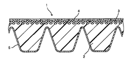
- FIG. 1 is a schematic cross-sectional view showing an example of a V-ribbed belt of the present invention.
- FIG. 2 is a schematic diagram for explaining a method of measuring a contact angle in the embodiment.
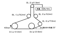
- FIG. 3 is a schematic diagram for explaining a method of measuring a friction coefficient in the embodiment.
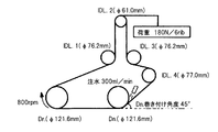
- FIG. 4 is a schematic diagram for explaining a method of measuring a friction coefficient (during water injection) in the embodiment.
- FIG. 5 is a schematic view for explaining a durability test in the example.
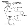
- FIG. 6 is a schematic diagram for explaining a misalignment pronunciation evaluation test in the embodiment.
- the fiber member (surfactant-containing fiber member) of the present invention is formed of a specific fiber (A) and contains a surfactant (or a surfactant is attached).
- the fiber member includes the fiber (A) and the surfactant. Then, as will be described later, such a fiber member covers the surface of the friction transmission portion constituting the transmission belt [the surface of the transmission belt that can contact (or contact with the pulley)] (or the friction transmission portion). It can be used as a fiber member for lamination on the surface.
- the fiber member is formed of fibers (A), and the fibers (A) include at least water-absorbing fibers (sometimes referred to as water-absorbing fibers (A1), fibers (A1), and the like).
- water-absorbing fibers examples include vinyl alcohol fibers (polyvinyl alcohol, ethylene-vinyl alcohol copolymer fibers, vinylon, etc.), cellulose fibers [cellulose fibers (plants, animals or Cellulose fibers derived from bacteria, etc.), cellulose derivative fibers] and the like.
- vinyl alcohol fibers polyvinyl alcohol, ethylene-vinyl alcohol copolymer fibers, vinylon, etc.
- cellulose fibers cellulose fibers (plants, animals or Cellulose fibers derived from bacteria, etc.), cellulose derivative fibers] and the like.
- cellulose fibers include wood pulp (conifers, hardwood pulp, etc.), bamboo fibers, sugarcane fibers, seed hair fibers (cotton fibers (cotton linters), kapok, etc.), gin leather fibers (hemp, kouzo, mitsumata, etc.), Examples thereof include cellulose fibers (pulp fibers) derived from natural plants such as leaf fibers (manila hemp, New Zealand hemp, etc.); cellulose fibers derived from animals such as squirt cellulose; bacterial cellulose fibers; Examples of the cellulose derivative fiber include cellulose ester fiber; regenerated cellulose fiber (rayon, cupra, lyocell, etc.) and the like. Polyamide fibers (such as polyamide 6 fibers, polyamide 66 fibers, and polyamide 46 fibers) and animal-derived fibers (wool, silk, etc.) can also be used as the water-absorbing fibers.
- cellulose fibers include wood pulp (conifers, hardwood pulp, etc.), bamboo fibers,
- the water-absorbing fiber may be a composite fiber in which at least part or all of the surface of the core material or core yarn is covered with the water-absorbing fiber component (water-absorbing fiber component).
- the core material or core yarn may be hydrophobic or non-water-absorbing, and may be hydrophilic or water-absorbing.
- the core material or core yarn may be a fiber exemplified below, for example, a non-water-absorbing fiber such as a polyolefin fiber, an acrylic fiber, a polyester fiber, or a polyurethane fiber.
- Water absorbing fibers may be used alone or in combination of two or more.
- the water absorbing fiber may contain at least a cellulosic fiber (particularly cotton fiber) and / or a regenerated cellulose fiber.
- the ratio of the water absorbing fiber (A1) with respect to the whole fiber (A) can be selected from the range of about 1% by mass or more (for example, 3% by mass or more), for example, 5% by mass or more (for example, 7% by mass or more). ), Preferably 10% by weight or more (for example, 12% by weight or more), more preferably 15% by weight or more (for example, 17% by weight or more), particularly 20% by weight or more (for example, 22% by weight or more), particularly preferably It may be 25% by mass or more (for example, 27% by mass or more).
- the fiber (A) only needs to contain at least the water-absorbing fiber (A1), and further, non-water-absorbing fibers (other fibers, fibers other than water-absorbing fibers) (non-water-absorbing fibers (A2), fibers (A2) ) May be included.
- non-water-absorbing fibers other fibers, fibers other than water-absorbing fibers
- it is easy to achieve high silence (and power transmission) while improving or improving the durability of the belt (or fiber member).
- non-water-absorbing fibers include, for example, polyolefin fibers (polyethylene fibers, polypropylene fibers, etc.), non-water-absorbing polyamide fibers (aramid fibers, etc.) Aromatic polyamide fibers, etc.), acrylic fibers, polyester fibers [polyethylene terephthalate (PET) fibers, polypropylene terephthalate (PPT) fibers, polytrimethylene terephthalate (PTT) fibers, polyethylene naphthalate (PEN) fibers, etc.
- PET polyethylene terephthalate
- PPT polypropylene terephthalate
- PTT polytrimethylene terephthalate
- PEN polyethylene naphthalate
- PBO polyparaphenylene benzobisoxazole
- Non-water absorbent fibers may be used alone or in combination of two or more.
- the non-water-absorbing fibers may include, in particular, elastic fibers [or elastic yarns, polyurethane fibers (or polyurethane elastic yarns or spandex), etc.] among these.
- the stretchable fiber (or elastic yarn) may be a fiber (or yarn) imparted with stretchability by stretch processing (for example, Woolley processing, crimping processing, etc.).
- the non-water-absorbing fiber may include at least a stretchable fiber.
- the ratio of the stretch fiber to the entire non-water absorbent fiber is, for example, 1% by mass or more (eg, 3 to 100% by mass), preferably 5% by mass or more (eg, 7 to 90% by mass), more preferably 10% by mass or more (for example, 12 to 80% by mass).
- 99/1 to 5/95 eg, 98/2 to 8/92
- 98/2 to 10/90 eg, 97/3 to 12/88
- May be about 96/4 to 15/85 eg, 95/5 to 17/83
- Fiber water-absorbing fiber, non-water-absorbing fiber
- the yarn may be a monofilament yarn or a multifilament yarn.
- the multifilament yarn may be a non-twisted yarn or a twisted yarn.
- the twisted yarn may be a yarn (for example, various twisted yarns, piece twisted yarns, rung twisted yarns, and the like) obtained by twisting a plurality of twisted yarns as a lower twisted yarn, and a twisted yarn obtained by twisting a twisted yarn and a single yarn as a lower twisted yarn (for example, , Wall twisted yarn, etc.).
- a yarn for example, various twisted yarns, piece twisted yarns, rung twisted yarns, and the like obtained by twisting a plurality of twisted yarns as a lower twisted yarn, and a twisted yarn obtained by twisting a twisted yarn and a single yarn as a lower twisted yarn (for example, , Wall twisted yarn, etc.).
- the multifilament yarn may be a composite yarn (or composite fiber) composed of two or more kinds of fibers (or yarns).
- a composite yarn (twisted yarn) may be a covering yarn [a yarn (twisted yarn) including a core yarn and a sheath yarn wound around (covered) the core yarn].
- the multifilament yarn (or twisted yarn) is composed of water-absorbing fibers (water-absorbing fiber yarns, monofilaments of water-absorbing fibers) or non-water-absorbing fibers [or non-water-absorbing fiber yarns such as the non-water-absorbing fibers (for example, polyurethane). Elastic fibers such as fibers)], and may contain water-absorbing fibers and non-water-absorbing fibers.
- the composite yarn containing water-absorbing fibers is a composite yarn conjugated with two or more types of water-absorbing fibers, a composite yarn conjugated with water-absorbing fibers and non-water-absorbing fibers, a covering yarn containing water-absorbing fibers, etc.
- a covering yarn may be preferably used from the viewpoint of stretchability.
- the covering yarn containing a water-absorbing fiber may contain a water-absorbing fiber (water-absorbing fiber yarn) for both the core yarn and the sheath yarn, and either one (particularly the sheath yarn) is a water-absorbing fiber (cotton fiber).
- Etc.) and the other (particularly the core yarn) may contain non-water-absorbing fibers (for example, stretchable fibers such as polyurethane fibers).
- the core yarn is often made of non-water-absorbing fiber and the sheath yarn is often made of water-absorbing fiber.
- the composite yarn containing only non-water-absorbing fibers is a composite yarn containing two or more types of non-water-absorbing fibers [for example, a composite yarn conjugated with two or more types of polyester fibers (for example, PET fibers and PTT fibers).
- a covering yarn in which both the core yarn and the sheath yarn are made of non-water-absorbing fibers [for example, one of the core yarn and the sheath yarn made of elastic fiber, that is, the core yarn is made of polyurethane.
- a covering yarn made of stretchable fibers such as fibers and sheath yarn made of polyester fibers (PET fibers, etc.).
- the fineness of the yarn depends on the form of the fiber member, but may be, for example, about 20 to 600 dtex, preferably about 50 to 300 dtex.
- the fiber member of the present invention is formed of fiber (A).
- a fiber member (form of the fiber member) is not particularly limited as long as it can cover the friction transmission surface of the transmission belt, but is usually in the form of a cloth (or canvas) such as a knitted fabric, a woven fabric, or a non-woven fabric. May be.
- a knitted fabric fiber member is particularly preferable in the present invention.
- the knitted fabric is suitable because it is excellent in stretchability and can be easily matched to the contour (shape) of the friction transmission surface.
- the knitted fabric is a fabric having a structure in which one or two or more knitting yarns form a mesh (loop), and the next yarn is hooked on the loop to continuously create a new loop. That is, the knitted fabric is formed by making a loop without crossing yarns linearly.
- the knitted fabric may be either weft knitted (or knitted fabric knitted by weft knitting) or warp knitted (or knitted fabric knitted by warp knitting).
- Examples of the weft knitting include a flat knitting (tengu knitting), a rubber knitting, a Kanoko knitting, and a smooth knitting.
- Examples of warp knitting or warp knitting structure) include single denby, single cord, tricot, and half tricot.
- weft knitting or knitted fabric knitted by weft knitting
- flat knitting or Kanoko knitting (weft knitting having a flat knitting or Kanoko knitting organization) is particularly preferable.
- a fiber (A) can be used suitably according to the form of a fiber member.
- the fiber member (for example, knitted fabric) of the said form can be formed with a water absorbing fiber or its thread
- the fiber (A) contains non-water-absorbing fibers, for example, (i) only the water-absorbing fibers (or yarns containing only water-absorbing fibers) and only the non-water-absorbing fibers (or non-water-absorbing fibers).
- a fiber member (knitted fabric or the like) may be formed using (ii) a yarn containing water-absorbing fibers and non-water-absorbing fibers (for example, twisted yarns such as covering yarns).
- a fiber member may be formed, and (iii) a fiber member using a yarn containing a water-absorbing fiber and a non-water-absorbing fiber, and a yarn containing only a water-absorbing fiber and / or a yarn containing only a non-water-absorbing fiber. May be formed.
- adhesion treatment examples include immersion treatment in a resin-based treatment solution in which an adhesive component [eg, epoxy compound, isocyanate compound] is dissolved in an organic solvent (toluene, xylene, methyl ethyl ketone, etc.), resorcin-formalin, and the like.
- an adhesive component eg, epoxy compound, isocyanate compound
- an organic solvent toluene, xylene, methyl ethyl ketone, etc.
- -An immersion treatment in a latex liquid (RFL liquid) and an immersion treatment in a rubber paste obtained by dissolving a rubber composition in an organic solvent Other methods of adhesion treatment include, for example, a friction treatment in which a fiber member and a rubber composition are passed through a calender roll and the rubber composition is imprinted on the fiber member, a spreading treatment in which rubber paste is applied to the fiber member, and a fiber member.
- a coating treatment for laminating a rubber composition can also be employed.
- the basis weight of the fiber member may be, for example, about 50 to 500 g / m 2 , preferably about 80 to 400 g / m 2 , and more preferably about 100 to 350 g / m 2 .
- the thickness (average thickness) of the fiber member may be, for example, about 0.1 to 3 mm, preferably about 0.2 to 2 mm, and more preferably about 0.3 to 1 mm.
- the fiber member of the present invention is formed of the specific fiber (A) as described above and contains a surfactant.
- the fiber member of the present invention includes a main body formed of the fiber (A) (hereinafter sometimes referred to as “main body of the fiber member” or “main body”) and a surfactant.
- the form in which the surfactant is contained is not particularly limited, but the surfactant is often attached to the fiber member (or the fiber (A) or the main body forming the fiber member).
- the fiber member often includes a main body formed of the fiber (A) and a surfactant attached to the main body (or the fiber (A) forming the main body).
- Surfactant is a general term for substances that have in their molecules a hydrophilic part (hydrophilic group) that is compatible with water and a hydrophobic part (hydrophobic group, lipophilic group) that is compatible with oil.
- hydrophilic group hydrophilic group
- hydrophobic part hydrophobic group, lipophilic group
- a surfactant is contained in the fiber member, and by combining the water-absorbing fiber and the surfactant, the surface tension of the water droplets attached to the friction transmission surface by the surfactant is reduced, and the water is wetted. It is possible to improve the performance and to absorb water with the water-absorbing fiber efficiently by spreading water on the friction transmission surface.
- the surfactant is not particularly limited, and ionic surfactants and nonionic surfactants can be used.
- the nonionic surfactant may be, for example, a polyethylene glycol type (polyoxyethylene type) nonionic surfactant and a polyhydric alcohol type nonionic surfactant.
- Polyethylene glycol type nonionic surfactants have a hydrophilic group formed by adding ethylene oxide to a hydrophobic base component having a hydrophobic group, such as higher alcohol, alkylphenol, higher fatty acid, higher polyhydric alcohol higher fatty acid ester, higher fatty acid amide, and polypropylene glycol. It is a given nonionic surfactant.
- Examples of the higher alcohol as the hydrophobic base component include C 10-30 saturated alcohols such as lauryl alcohol, tridecyl alcohol, tetradecyl alcohol, cetyl alcohol, octadecyl alcohol, aralkyl alcohol, and C 10-26 A saturated alcohol etc. can be illustrated.
- Examples of the alkylphenol include C 4-16 alkylphenol such as octylphenol and nonylphenol.
- Higher fatty acids of the hydrophobic base component include saturated fatty acids [eg C 10-30 saturated fatty acids such as myristic acid, palmitic acid, stearic acid, arachidic acid, behenic acid, lignoceric acid, serotic acid, montanic acid, preferably C 12-28 saturated fatty acids, more preferably C 14-26 saturated fatty acids, especially C 16-22 saturated fatty acids; oxycarboxylic acids such as hydroxystearic acid], unsaturated fatty acids [eg oleic acid, erucic acid, erucic acid , C 10-30 unsaturated fatty acids such as linoleic acid, linolenic acid, and eleostearic acid]. These higher fatty acids may be used alone or in combination of two or more.
- saturated fatty acids eg C 10-30 saturated fatty acids such as myristic acid, palmitic acid, stearic acid, arachidic acid, behenic acid, lignoceric acid, serotic acid, mont
- the polyhydric alcohol higher fatty acid ester is an ester of a polyhydric alcohol and the higher fatty acid and has an unreacted hydroxyl group.
- polyhydric alcohols include alkanediols (such as C 2-10 alkanediols such as ethylene glycol, propylene glycol, and butanediol), alkanetriols (such as glycerin, trimethylolethane, trimethylolpropane), and alkanetetraols (pentaerythritol, Examples thereof include diglycerin and the like, alkanehexaol (such as dipentaerythritol, sorbitol, and sorbit), alkaneoctaol (such as sucrose), and alkylene oxide adducts thereof (such as C 2-4 alkylene oxide adducts).
- oxyethylene ethylene oxide or “ethylene glycol”
- EO ethylene glycol
- PO oxypropylene
- the polyethylene glycol type Specific examples of the ionic surfactant include, for example, poly EO higher alcohol ether (poly EO 10-26 alkyl ether such as poly EO lauryl ether and poly EO stearyl ether), poly EO poly PO higher alcohol ether (for example, poly EO).
- poly POC 10-26 alkyl ether poly EO octylphenyl ether, alkylphenol -EO adduct such as poly EO nonyl phenyl ether; poly EO monolaurate, poly EO monooleate, such as poly EO monostearate fat Acid -EO adduct; glycerol mono- or di-higher fatty acid esters -EO adduct (glycerin mono- or dilaurate, glycerin mono- or dipalmitate, glyceryl mono- or distearate, glycerin mono- or di-C 10-26 fatty acid esters such as glycerol mono- or dioleate EO adduct), pentaerythritol higher fatty acid ester-EO adduct (pentaerythritol mono to tri C 10-26 fatty acid ester-EO adduct such as pentaerythritol distearate-EO
- the polyhydric alcohol type nonionic surfactant is a non-ionic surfactant in which a hydrophobic group such as a higher fatty acid is bonded to the polyhydric alcohol (particularly, alkanetriol or alkanehexaol such as glycerol, diglycerin, pentaerythritol, sucrose, or sorbitol). It is an ionic surfactant.
- polyhydric alcohol type nonionic surfactant examples include glycerin fatty acid esters such as glycerin monostearate and glycerin monooleate, pentaerythritol fatty acid esters such as pentaerythritol monostearate and pentaerythritol beef tallow fatty acid ester, Sorbitan fatty acid esters such as sorbitan monolaurate, sorbitan monostearate, sorbitol fatty acid esters such as sorbitol monostearate, sucrose fatty acid esters, alkyl ethers of polyhydric alcohols, fatty acid amides of alkanolamines such as coconut fatty acid diethanolamide, Examples thereof include alkyl polyglycosides. These polyhydric alcohol type nonionic surfactants can also be used alone or in combination of two or more, and may be used in combination with the polyethylene glycol type nonionic surfactant.
- ionic surfactants include sulfonates (alkyl benzene sulfonates, ⁇ -olefin sulfonates, alkane sulfonates, etc.), sulfates (alkyl sulfates, polyEO alkyl ether sulfates, etc.), long Chain fatty acid salts, naphthalene sulfonic acid formalin condensates, phosphoric acid esters (aliphatic phosphoric acid ester type, aromatic phosphoric acid ester type, alkyl phosphoric acid salt, etc.), anionic surfactants such as sulfosuccinic acid ester salts, alkyltrimethylammonium It may be a cationic surfactant such as a salt or a dialkyldimethylammonium salt, or an amphoteric surfactant such as an alkylbetaine or imidazoline derivative.
- Preferred surfactants are nonionic surfactants, particularly polyethylene glycol type nonionic surfactants. Therefore, the surfactant may contain at least a nonionic surfactant (particularly, a polyethylene glycol type nonionic surfactant).
- the degree of affinity of the surfactant with water and oil can be represented by an HLB (Hydrophile-Lipophile-Balance) value.
- the HLB of the surfactant is in the range of 0 to 20, and the closer to 0, the higher the lipophilicity, and the closer to 20, the higher the hydrophilicity.
- the HLB value of the surfactant is not particularly limited, but may be about 5 to 15, particularly about 7 to 15.
- the boiling point of the surfactant is not particularly limited, but a surfactant having a boiling point higher than the rubber vulcanization temperature described later can also be used.
- the melting point of the surfactant is preferably as low as possible, and the lower limit is not particularly limited.
- the melting point of the surfactant is preferably room temperature or lower, for example, 20 ° C. or lower (eg, ⁇ 40 ° C. to 20 ° C.), preferably ⁇ 35 ° C. to 15 ° C. (eg, ⁇ 30 ° C. to 10 ° C.), More preferably, it is about ⁇ 35 ° C. to 5 ° C., and may usually be about 0 ° C. or less (eg, ⁇ 35 ° C. to ⁇ 5 ° C.).
- the surfactant may be usually liquid at room temperature (20 to 25 ° C.). In addition, it is easy to make a fiber member contain (or adhere) a surfactant efficiently by making melting
- the content ratio (or adhesion ratio) of the surfactant is, for example, in the range of 0.1 g or more (for example, 0.3 to 300 g) per 1 m 2 of the fiber member (or one side of the fiber member).
- 0.5 to 200 g eg, 0.7 to 150 g
- 1 to 100 g eg, 1.2 to 90 g
- more preferably 1.5 to 80 g eg, 2 to 70 g
- 3 g or more [eg, 5 g or more (eg, 6 to 100 g), preferably 8 g or more (eg, 9 to 80 g), more preferably 10 g or more (eg, 12 to 60 g)).
- the upper limit of the content ratio of the surfactant is not particularly limited, but may be appropriately selected within a range in which the stickiness of the surfactant in the fiber member can be suppressed.
- the content ratio of the surfactant can also be selected from the same range as described above in the transmission belt of the present invention. However, as described later, when the vulcanization is performed after the fiber member is coated, a part of the surfactant is added. It may evaporate. In such a case, the amount to be vaporized in advance may be assumed, and the fiber member may be contained so that the content ratio after vaporization is in the above range.
- the surfactant content (attachment ratio) is, for example, 0.3 to 150 parts by mass (for example, 0) with respect to 100 parts by mass of the fiber (A) forming the fiber member (or the main body of the fiber member).
- 0.5 to 120 parts by weight preferably 0.7 to 100 parts by weight (eg 1 to 80 parts by weight), more preferably 2 to 70 parts by weight (eg 3 to 60 parts by weight), in particular 5 to 50 parts by weight.
- the method for producing the fiber member (fiber member containing a surfactant) of the present invention is particularly limited.
- a method of spraying a surfactant on a main body (or fiber (A)) of a fiber member formed of a fiber (A) containing a water-absorbing fiber (A1), a method of coating a surfactant, a surface activity is mentioned.
- a surfactant is applied to the surface of a cylindrical outer mold having a plurality of rib molds engraved on the inner peripheral surface, and vulcanized to form the surfactant. It can also be included in the member. Among these, from the viewpoint that the surfactant can be contained (or adhered) simply and uniformly, a method of immersing (immersing treatment) in the surfactant is preferable.
- the surfactant may be contained in a form containing a solvent (that is, in the form of a solution containing the surfactant), if necessary.
- a solvent can be appropriately selected according to the type of surfactant and the like, and is not particularly limited.
- hydrocarbons for example, aromatic hydrocarbons such as toluene and xylene
- ethers for example, Chain ethers such as diethyl ether; cyclic ethers such as dioxane and tetrahydrofuran
- ketones eg, chain ketones such as acetone and methyl ethyl ketone; cyclic ketones such as cyclohexanone
- esters eg, acetate esters such as ethyl acetate
- General-purpose solvents such as These solvents may be used alone or as a mixed solvent.
- the concentration of the surfactant is, for example, 0.1 to 80% by mass (for example, 0.2 to 60% by mass), preferably 0.3 to 50% by mass (for example, 0.8%). 4 to 40% by mass), more preferably about 0.5 to 30% by mass, especially 1% by mass or more [eg 2 to 50% by mass (eg 3 to 40% by mass), preferably 5% or more] To 30% by mass (for example, 7 to 25% by mass)].
- concentration By setting it as such a density
- the immersion time is not particularly limited, and is, for example, 1 minute or more (eg, 3 minutes to 10 hours), preferably 5 minutes or more (eg, 8 minutes to 6 hours), more preferably 10 minutes or more (eg, 15 minutes). (About 3 hours).
- the immersion temperature is not particularly limited, and may be, for example, about 10 ° C. to 60 ° C. When the temperature is too low, the fluidity of the solution or the surfactant is lowered, impregnation properties and workability are lowered, and when the temperature is too high, the solvent is volatilized and the concentration of the surfactant is changed (increased).
- the drying treatment may be performed under heating [for example, under heating at about 50 ° C. or higher (for example, 70 to 200 ° C.), preferably about 100 ° C. or higher (for example, 120 to 160 ° C.)).
- the drying time is not particularly limited, and may be, for example, 10 minutes to 120 minutes. If the drying time is too short, drying becomes insufficient, and if it is too long, the fiber member (particularly cellulose fiber such as cotton) changes color depending on the drying temperature.
- the fiber member of the present invention is a fiber member for covering the surface of the friction transmission part (power transmission part) of the transmission belt (transmission belt having a friction transmission part) [that is, the friction transmission surface (or power transmission surface)].
- the present invention also includes a transmission belt provided with such a fiber member. That is, the transmission belt of the present invention is a transmission belt having a friction transmission portion, and the surface of the friction transmission portion (friction transmission surface) is covered with the fiber member.
- the friction transmission surface is a surface that can contact the pulley (belt surface of the belt). Therefore, the friction transmission surface can come into contact with the pulley via the fiber member.
- the structure of such a transmission belt is not particularly limited as long as it has a friction transmission part.
- it includes at least a compression layer having a friction transmission part (or a compression layer forming the friction transmission part).
- a compression layer should just be provided with the friction transmission part, and the compression layer whole may comprise a friction transmission part.
- at least the friction transmission part (or friction transmission surface) is often formed of rubber (or a rubber composition), and the entire compression layer may be formed of rubber. In the present invention, even when the friction transmission portion is formed of rubber in this way, high silence can be ensured when wet.
- a typical power transmission belt includes a stretch layer that forms the back surface of the belt (the outer peripheral surface of the belt) and a compression layer (particularly a compression layer formed of rubber) that is formed on one surface side of the stretch layer and has a friction transmission portion. Rubber layer) and a core wire embedded in the longitudinal direction of the belt between the stretch layer and the compression layer in many cases. And in this invention, in such a transmission belt, the said fiber member is coat
- an adhesive layer may be provided between the compressed layer and the stretched layer as necessary.
- the core wire is not particularly limited as long as it can be embedded between the stretched layer and the compressed layer.
- the core wire may be embedded in the compressed layer, or may be embedded in the compressed layer while being in contact with the stretched layer.
- the core wire may be embedded in the adhesive layer, or the core wire may be embedded between the compression layer and the adhesive layer or between the adhesive layer and the stretched layer.
- the type of the transmission belt is not particularly limited, and examples thereof include a V belt, a V-ribbed belt, and a flat belt. Of these belts, a V-ribbed belt having high transmission efficiency is preferable.
- FIG. 1 is a schematic sectional view showing an example of a transmission belt (V-ribbed belt) of the present invention.
- the belt 1 includes a fiber member 5, a compression layer (compression rubber layer) 2 formed of a rubber composition, a core wire 3, and a cover in this order from the belt lower surface (inner peripheral surface, abdominal surface) to the belt upper surface (back surface).
- the stretched layer 4 made of canvas (woven fabric, knitted fabric, non-woven fabric, etc.) is laminated.
- the core wire 3 is embedded along the longitudinal direction of the belt, a part of which is in contact with the stretched layer 4 and the remaining part of which is in contact with the compressed layer 2.
- a plurality of V-shaped grooves extending in the longitudinal direction of the belt are formed in the compression layer 2, and a plurality of ribs having a V-shaped section (reverse trapezoidal shape) (3 in the example shown in FIG. 1) are formed between the grooves.
- the two inclined surfaces (surfaces) of the rib serving as the friction transmission portion form a friction transmission surface and contact the pulley to transmit power (friction transmission).
- the surface of the rib (friction transmission surface) is covered (covered) with the fiber member (knitted fabric or the like) 5.
- the stretch layer 4 may be formed of a rubber composition, and an adhesive layer may be provided between the compression layer 2 and the stretch layer 4.
- the compression layer may usually be formed of rubber (or a rubber composition).
- rubber rubber constituting the rubber composition
- known rubber components and / or elastomers such as diene rubber (natural rubber, isoprene rubber, butadiene rubber, chloroprene rubber, styrene butadiene rubber (SBR), acrylonitrile butadiene rubber) (Nitrile rubber), hydrogenated nitrile rubber (including mixed polymers of hydrogenated nitrile rubber and unsaturated carboxylic acid metal salt), ethylene- ⁇ -olefin elastomer, chlorosulfonated polyethylene rubber, alkylated chlorosulfonated polyethylene Examples thereof include rubber, epichlorohydrin rubber, acrylic rubber, silicone rubber, urethane rubber, and fluorine rubber.
- polystyrene resin ethylene-propylene rubber (EPR), ethylene-propylene rubber (EPR), free from harmful halogens, ozone-resistant, heat-resistant, cold-resistant, and economically superior.
- Ethylene- ⁇ -olefin rubbers such as ethylene-propylene-diene rubbers (EPDM, etc.) are preferred.
- the ratio of rubber to the entire compression layer is, for example, 20% by mass or more (for example, 25 to 80% by mass), preferably 30% by mass or more (for example, 35 to 75% by mass), More preferably, it may be 40% by mass or more (for example, 45 to 70% by mass).
- the compressed layer (or rubber or rubber composition forming the compressed rubber layer) may contain various additives as necessary.
- additives such as vulcanizing agents or crosslinking agents [for example, oximes (such as quinone dioxime), guanidines (such as diphenyl guanidine), metal oxides (magnesium oxide, oxidation) Zinc), organic peroxides (diacyl peroxide, peroxyester, dialkyl peroxide, etc.)], vulcanization aids, vulcanization accelerators, vulcanization retarders, reinforcing agents (carbon black, hydrous silica, etc.) Silicon oxide), metal oxides (for example, zinc oxide, magnesium oxide, calcium oxide, barium oxide, iron oxide, copper oxide, titanium oxide, aluminum oxide, etc.), fillers (clay, calcium carbonate, talc, mica, etc.) , Plasticizers, softeners (paraffin oils, oils such as naphthenic oils), processing agents or processing aids ( (Tearic acid, stearic acid metal salts, wax, paraffin, etc.), anti
- additives can be used alone or in combination, and are appropriately selected according to the type, application, performance, etc. of the rubber.
- the proportion of the additive can also be appropriately selected according to the type of rubber.
- the proportion of the reinforcing agent carbon black or the like
- the proportion of the reinforcing agent is 10 parts by mass or more (for example, 20 to 150 parts by mass), preferably 20 parts by mass or more (for example, 25 to 120 parts by mass) with respect to 100 parts by mass of rubber. More preferably, it may be 30 parts by mass or more (for example, 35 to 100 parts by mass) or 40 parts by mass or more (for example, 50 to 80 parts by mass).
- the compressed layer may or may not contain a surfactant (such as the compound exemplified above).
- the compression layer may contain short fibers.
- the short fibers include short fibers of the fibers exemplified in the above-mentioned fiber (A) [for example, cellulose fibers such as cotton and rayon, polyester fibers (PET fibers, etc.), polyamide fibers (aliphatic polyamides such as polyamide 6). Fiber, aramid fiber, etc.).
- the short fiber may be a water absorbent fiber.
- the short fibers may be used alone or in combination of two or more.
- the average fiber length of the short fibers may be, for example, about 0.1 to 30 mm (for example, 0.2 to 20 mm), preferably about 0.3 to 15 mm, and more preferably about 0.5 to 5 mm.
- These short fibers may be surface-treated with a surfactant, a silane coupling agent, an epoxy compound, an isocyanate compound, or the like, if necessary.
- the proportion of short fibers is, for example, about 0.5 to 50 parts by mass (for example, 1 to 40 parts by mass), preferably about 3 to 30 parts by mass (for example, 5 to 25 parts by mass) with respect to 100 parts by mass of rubber. It may be.
- the thickness of the compression layer can be appropriately selected depending on the type of belt, etc., but may be, for example, about 1 to 30 mm, preferably about 1.5 to 25 mm, and more preferably about 2 to 20 mm. .
- the core wire is not particularly limited, and may include, for example, synthetic fibers such as polyester fibers (polyalkylene arylate fibers) and polyamide fibers (such as aramid fibers), inorganic fibers such as carbon fibers, and the like.
- synthetic fibers such as polyester fibers (polyalkylene arylate fibers) and polyamide fibers (such as aramid fibers)
- inorganic fibers such as carbon fibers, and the like.
- the core wire usually a twisted cord using multifilament yarn (for example, various twists, single twists, rung twists, etc.) can be used.
- the average wire diameter (fiber diameter of the twisted cord) of the core wire may be, for example, about 0.5 to 3 mm, preferably about 0.6 to 2 mm, and more preferably about 0.7 to 1.5 mm.
- the core wire may be embedded in the longitudinal direction of the belt, or may be embedded in parallel at a predetermined pitch parallel to the longitudinal direction of the belt.
- the core wire may be subjected to various adhesion treatments with an epoxy compound, an isocyanate compound, etc., as with the short fiber.
- the stretch layer may be formed of the same rubber composition as the compression layer, or may be formed of a fabric (reinforcing fabric) such as a canvas.
- the reinforcing cloth examples include cloth materials such as woven cloth, wide-angle canvas, knitted cloth, and non-woven cloth. Of these, preferred are woven fabrics woven in the form of plain weave, twill weave, satin weave, etc., wide-angle canvas or knitted fabric in which the crossing angle between warp and weft is about 90 to 120 °.
- the fibers constituting the reinforcing cloth the fibers exemplified in the section of the fiber member (water-absorbing fibers, non-water-absorbing fibers, etc.) can be used.
- the reinforcing cloth may be subjected to an adhesion treatment (for example, an adhesion treatment exemplified in the section of the fiber member). Further, after the adhesion treatment [treatment with the RFL solution (immersion treatment etc.)], the rubber composition may be formed by friction or rubbing (coating) the rubber composition.
- an adhesion treatment for example, an adhesion treatment exemplified in the section of the fiber member.
- the rubber component constituting the stretch layer uses the same or the same type of rubber as the rubber component of the rubber composition of the compression layer. There are many cases to do. Further, the ratio of additives such as a vulcanizing agent or a crosslinking agent, a co-crosslinking agent or a crosslinking aid, and a vulcanization accelerator can be selected from the same range as that of the rubber composition of the compression layer.
- the rubber composition may further contain short fibers similar to those of the compression layer in order to suppress abnormal noise generated due to adhesion of the back rubber when the back surface is driven.
- the short fibers may be randomly oriented in the rubber composition. Further, the short fiber may be a short fiber partially bent.
- an uneven pattern may be provided on the surface of the stretched layer (the back surface of the belt) in order to suppress abnormal noise during backside driving.
- the uneven pattern include a knitted fabric pattern, a woven fabric pattern, a suede woven fabric pattern, and an embossed pattern. Of these patterns, a woven fabric pattern and an embossed pattern are preferable. Furthermore, you may coat
- the thickness of the stretched layer can be appropriately selected depending on the type of belt, but may be, for example, about 0.5 to 10 mm, preferably 0.7 to 8 mm, and more preferably about 1 to 5 mm.
- the adhesive layer (adhesive layer) As described above, the adhesive layer is not always necessary.
- the adhesive layer (adhesive rubber layer) can be composed of, for example, the same rubber composition as the compression layer (compressed rubber layer) (rubber composition containing a rubber component such as ethylene- ⁇ -olefin elastomer).
- the rubber composition of the adhesive layer as the rubber component, the same type or type of rubber as the rubber component of the rubber composition of the compressed rubber layer is often used.
- the ratio of additives such as a vulcanizing agent or a crosslinking agent, a co-crosslinking agent or a crosslinking aid, and a vulcanization accelerator can be selected from the same range as that of the rubber composition of the compression layer.
- the rubber composition of the adhesive layer may further contain an adhesion improver (resorcin-formaldehyde cocondensate, amino resin, etc.).
- the thickness of the adhesive layer can be appropriately selected according to the type of belt, but may be, for example, about 0.2 to 5 mm, preferably about 0.3 to 3 mm, and more preferably about 0.5 to 2 mm.
- the transmission belt of the present invention is excellent in quietness, particularly in quietness.
- Such excellent quietness can use the contact angle of water on the friction transmission surface as one index.
- the contact angle (contact angle between the surface of the friction transmission portion and the water) after 5 seconds has elapsed after dropping water on the surface of the friction transmission portion of the transmission belt of the present invention is 50 ° or less, preferably 40 ° or less. More preferably, it may be 30 ° or less, and in particular, it may be 0 ° (or almost 0 °).
- the method for producing the transmission belt of the present invention is not particularly limited, and a known or conventional method can be adopted.
- a fiber member, a compression layer composed of rubber (or rubber composition), a core wire, and an extension layer are laminated, and the resulting laminate is formed into a cylindrical shape with a mold and vulcanized. This can be formed by forming a sleeve and cutting the vulcanized sleeve to a predetermined width.
- the V-ribbed belt can be manufactured by the following method, for example.
- a cylindrical inner mold having a flexible jacket attached to the outer peripheral surface is used as the inner mold, and an unvulcanized stretch layer sheet is wound around the outer peripheral flexible jacket, and a cord is spiraled on the sheet.
- the laminate is prepared by spinning the sheet into a shape and winding the unvulcanized sheet for the compression layer and the fiber member.
- an outer mold that can be attached to the inner mold a cylindrical outer mold in which a plurality of rib molds are engraved on the inner peripheral surface is used, and an inner mold in which the laminated body is wound in the outer mold. Install concentrically.
- the flexible jacket is expanded toward the inner peripheral surface (rib type) of the outer mold, and the laminate (compressed layer) is pressed into the rib mold and vulcanized. Then, after extracting the inner mold from the outer mold and removing the vulcanized rubber sleeve having a plurality of ribs from the outer mold, the vulcanized rubber sleeve is cut to a predetermined width in the longitudinal direction of the belt using a cutter. Finish the ribbed belt.
- a laminate including a stretch layer, a core wire, and a compression layer can be expanded at a time to be finished into a sleeve having a plurality of ribs (or a V-ribbed belt).
- the present invention will be described in more detail based on examples, but the present invention is not limited to these examples.
- the measuring method of the adhesion amount of surfactant, the measuring method or evaluation method of each physical property, etc. are shown below.
- N 1 is the mass of the fiber member (main body of the fiber member) before the adhesion treatment
- N 2 is the mass of the fiber member after the adhesion treatment
- S N is the area of the fiber member
- R 1 is not subjected to the adhesion treatment.
- mass after vulcanization of the belt R 2 is the mass of the vulcanized belt was attached processing
- S R represents the area of the fiber member in the belt.
- the adhesion amount (part by mass) of the surfactant per 100 parts by mass of the fiber (A) (or the main body of the fiber member) was also determined.
- the contact angle is measured at room temperature (25 ° C.) using a fully automatic contact angle meter (Kyowa Interface Science Co., Ltd., model CA-W) to measure r and h from a projected photograph of a dropped water drop. Calculated using (3). The measurement calculated the contact angle immediately after dropping (after 5 seconds). The smaller the contact angle ⁇ , the better the friction transmission surface is with water, and particularly when the contact angle ⁇ is 0 °, it indicates that water droplets are extended and wetted on the entire contact surface.
- a V-ribbed belt is hung on each pulley of the test machine, and the rotational speed of the driving pulley is 400 rpm and the belt winding angle around the driven pulley is 20 ° under a room temperature (25 ° C.) condition, and a constant load [180 N / 6 Rib (Rib)] is applied and the belt is run to increase the torque of the driven pulley from 0 to a maximum of 20 Nm, and the torque of the driven pulley when the belt slip speed with respect to the driven pulley reaches the maximum (100% slip). From the value, the friction coefficient ⁇ was determined using the following equation.
- T1 is the tension on the tension side
- T2 is the tension on the loose side
- ⁇ is the belt winding angle around the driven pulley, which can be obtained by the following equations, respectively.
- the high temperature low tension reverse bending test was performed using a 120 mm diameter drive pulley (Dr.), a 75 mm diameter idler pulley (IDL.), A 120 mm diameter driven pulley (Dn.), And a 60 mm diameter pulley.
- the test was performed using a testing machine in which tension pulleys (Ten.) Were arranged in order.
- a V-ribbed belt is hung on each pulley of the test machine, the rotational speed of the driving pulley is 4900 rpm, the belt winding angle around the idler pulley and the tension pulley is 90 °, the driven pulley load is 10.4 kW, and a constant load [91 kg / 6 Rib (rib)] was applied, and the belt was run at an ambient temperature of 120 ° C.
- the running time was censored after 300 hours, and the durability of the belt was evaluated according to the following criteria.
- the misalignment pronunciation evaluation test (sound generation limit angle) includes a 101 mm diameter drive pulley (Dr.), an 80 mm diameter idler pulley (IDL.1), and a 128 mm diameter misalignment pulley (W / P), an idler pulley (IDL.2) with a diameter of 80 mm, a tension pulley (Ten.) With a diameter of 61 mm, and an idler pulley (IDL.3) with a diameter of 80 mm were used in this order.
- the axial separation (span length) of the idler pulley (IDL.1) and the misalignment pulley was set to 135 mm, and all the pulleys were adjusted to be positioned on the same plane (misalignment angle 0 °).
- a V-ribbed belt is hung on each pulley of the test machine, and the tension is applied so that the rotational speed of the drive pulley is 1000 rpm and the belt tension is 50 N / Rib (rib) under the room temperature (25 ° C.) condition.
- the belt was run while injecting 5 cc of water periodically (about 30 seconds) on the friction transmission surface of the V-ribbed belt.
- the misalignment pulley was shifted to the front side with respect to each pulley, and the angle (sound generation limit angle) when sound generation occurred near the entrance of the misalignment pulley was obtained.
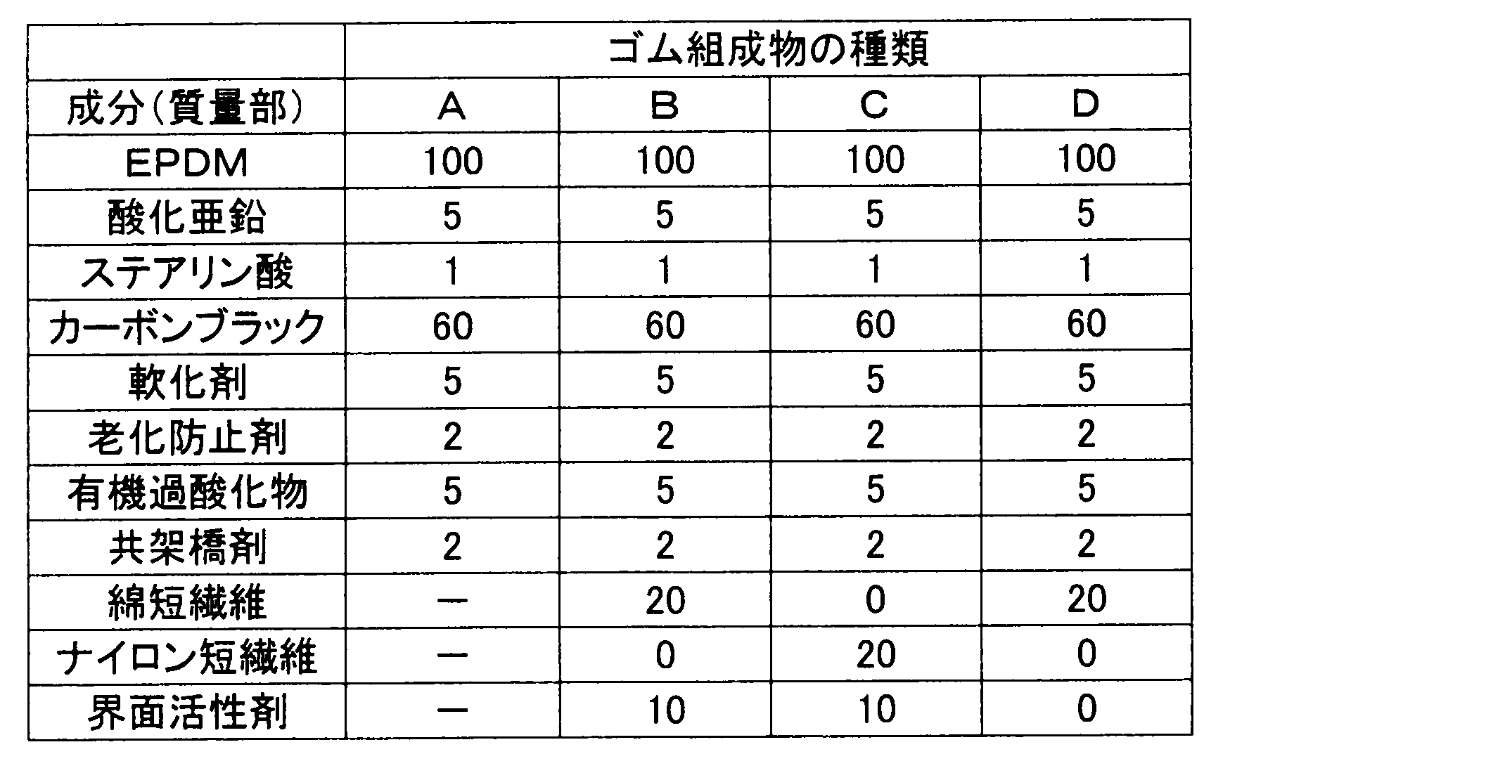
- Rubber compositions A to D shown in Table 1 were kneaded with a Banbury mixer, and the kneaded rubber was passed through a calender roll to prepare an unvulcanized rolled rubber sheet (compression layer sheet) having a predetermined thickness. Further, using the rubber composition A shown in Table 1, a stretch layer sheet was produced in the same manner as described above.
- the ratio of each component in the rubber composition shown in Table 1 is part by mass.
- the components in the rubber composition are as follows.
- EPDM “Nodel IP4640” manufactured by Dow Chemical Zinc oxide: manufactured by Shodo Chemical Industry Co., Ltd., "Zinc oxide 3 types” Carbon black: “Seast V” manufactured by Tokai Carbon Co., Ltd., average particle size 55 nm Softener: Paraffinic oil, manufactured by Idemitsu Kosan Co., Ltd. “NS-90” Anti-aging agent: “NOCRACK MB” manufactured by Ouchi Shinsei Chemical Industry Co., Ltd. Organic peroxide: NOF Corporation, “Park Mill D-40” Co-crosslinking agent: “Barunok PM” manufactured by Ouchi Shinsei Chemical Industry Co., Ltd.
- Cotton short fiber Denim, average fiber diameter 13 ⁇ m, average fiber length 3mm
- Nylon short fiber 66 nylon, average fiber diameter 27 ⁇ m, average fiber length 3 mm
- Surfactant Polyoxyalkylene alkyl ether, manufactured by Kao Corporation, “Emulgen”
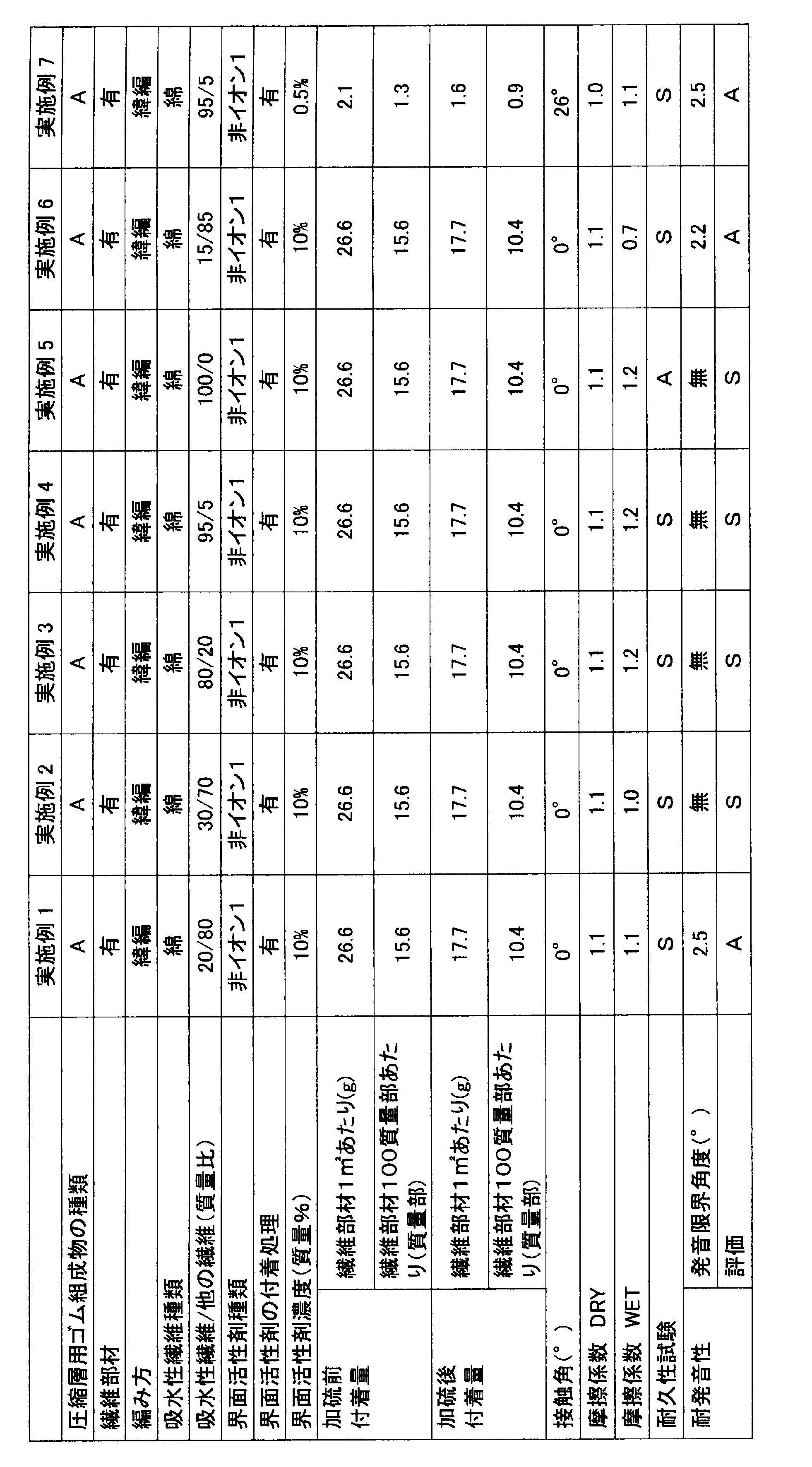
- First yarn (yarn containing water-absorbing fibers): Covering yarn in which polyurethane (PU) core yarn is covered with cotton, 50th thick second yarn (yarn consisting only of non-absorbent fibers): Polyurethane ( (PU) core yarn covered with polyethylene terephthalate (PET), thickness 56dtex In Example 5, only a cotton yarn was used as the knitting yarn, and in Comparative Examples 2 and 6, only the second yarn was used as the knitting yarn, and a weft knitted fabric was similarly produced. Tables 2 to 4 show the ratios of cotton fibers (water-absorbing fibers) and other fibers (non-water-absorbing stretchable fibers, etc.) other than cotton fibers to the entire fibers constituting the knitted fabric (fiber member).
- Examples 1 to 9 and Comparative Example 2 were further subjected to a surfactant adhesion treatment.
- the adhesion treatment was performed by immersing the knitted fabric in a toluene solution containing a surfactant at a concentration shown in Table 2 at room temperature (25 ° C.) for 30 minutes and drying in an oven at 143 ° C. for 10 minutes.
- nonionic 1 the following nonionic surfactant (hereinafter simply referred to as “nonionic 1”) was used.
- Non-ion 1 polyoxyalkylene alkyl ether (trade name “Emulgen” manufactured by Kao Corporation)
- nonionic 2 the following nonionic surfactant (hereinafter simply referred to as “nonionic 2”) was used, and the same procedure as in Example 4 and Example 7 was performed. A fiber member was prepared.
- Non-ion 2 Polyoxyethylene tridecyl ether (trade name “Pegnol” manufactured by Toho Chemical Co., Ltd.)
- Example 12 A fiber member was prepared in the same manner as in Example 7 except that the following anionic surfactant (hereinafter simply referred to as “ion”) was used instead of the surfactant in Example 7.
- ion anionic surfactant
- Example 13 Instead of the first yarn (water-absorbing fiber) of Example 2 [covering yarn in which the core yarn of polyurethane (PU) is covered with cotton, 50th in thickness], other water-absorbing fibers [of polyurethane (PU) A fiber member was prepared in the same manner as in Example 2, except that a weft knitted fabric was prepared using a covering yarn (rayon yarn) having a core yarn coated with rayon and a thickness of 30 (dtex).
- Example 14 A fiber member was prepared in the same manner as in Example 2 except that a warp knitted fabric was prepared using the first yarn (water absorbent fiber) and the second yarn (non-water absorbent fiber) of Example 2.
- the knitted fabric of the warp knitted fabric is a single denby (single layer warp knitted fabric).
- a cylindrical inner mold with a flexible jacket attached to the outer peripheral surface is used as the inner mold, and an unvulcanized stretch layer sheet is wrapped around the flexible jacket on the outer peripheral surface. Spinning was performed, and the unvulcanized compression layer sheet and fiber member (knitted fabric) shown in Tables 2 to 4 were wound in this order to prepare a laminate.
- polyester core wire of 1100 dtex / 2x3 structure was used for the core wire.
- the core wire is dipped in resorcin-formalin-latex solution (RFL solution) and then coated with a treatment solution in which a rubber composition containing EPDM is dissolved in an organic solvent (toluene). Went.
- a cylindrical outer mold in which a plurality of rib molds are engraved on the inner peripheral surface is used, and an inner mold in which the laminate is wound is provided in the outer mold.
- the flexible jacket was expanded toward the inner peripheral surface (rib type) of the outer mold, and the laminate (compressed layer) was press-fitted into the rib mold and vulcanized.
- the vulcanized rubber sleeve is cut to a predetermined width in the longitudinal direction of the belt using a cutter.
- a ribbed belt (6 ribs, circumference of 1200 mm) was obtained.
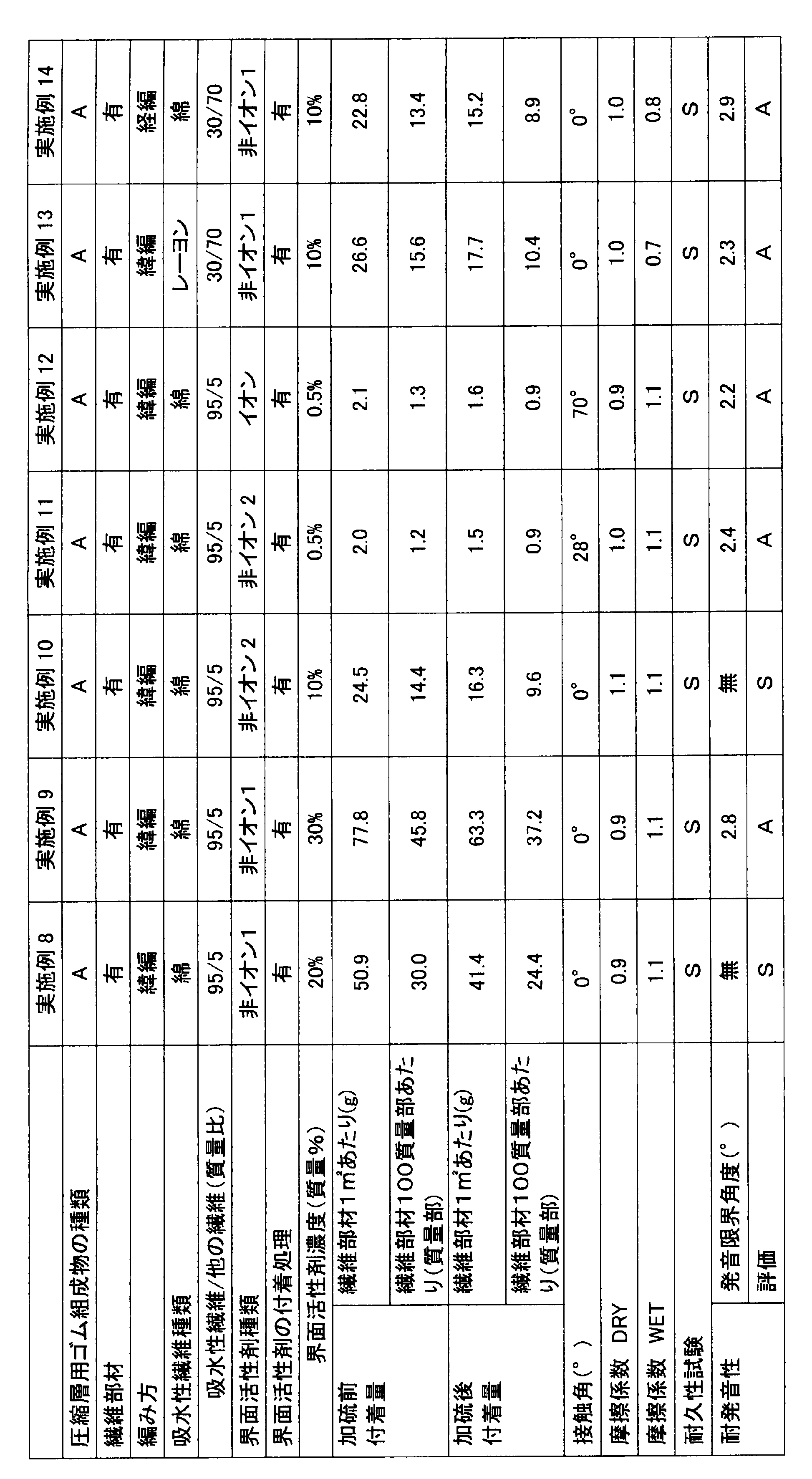
- the combination of the water-absorbing fiber and the non-water-absorbing fiber and adjusting the adhesion ratio of the surfactant can achieve both a high level of silence and durability.
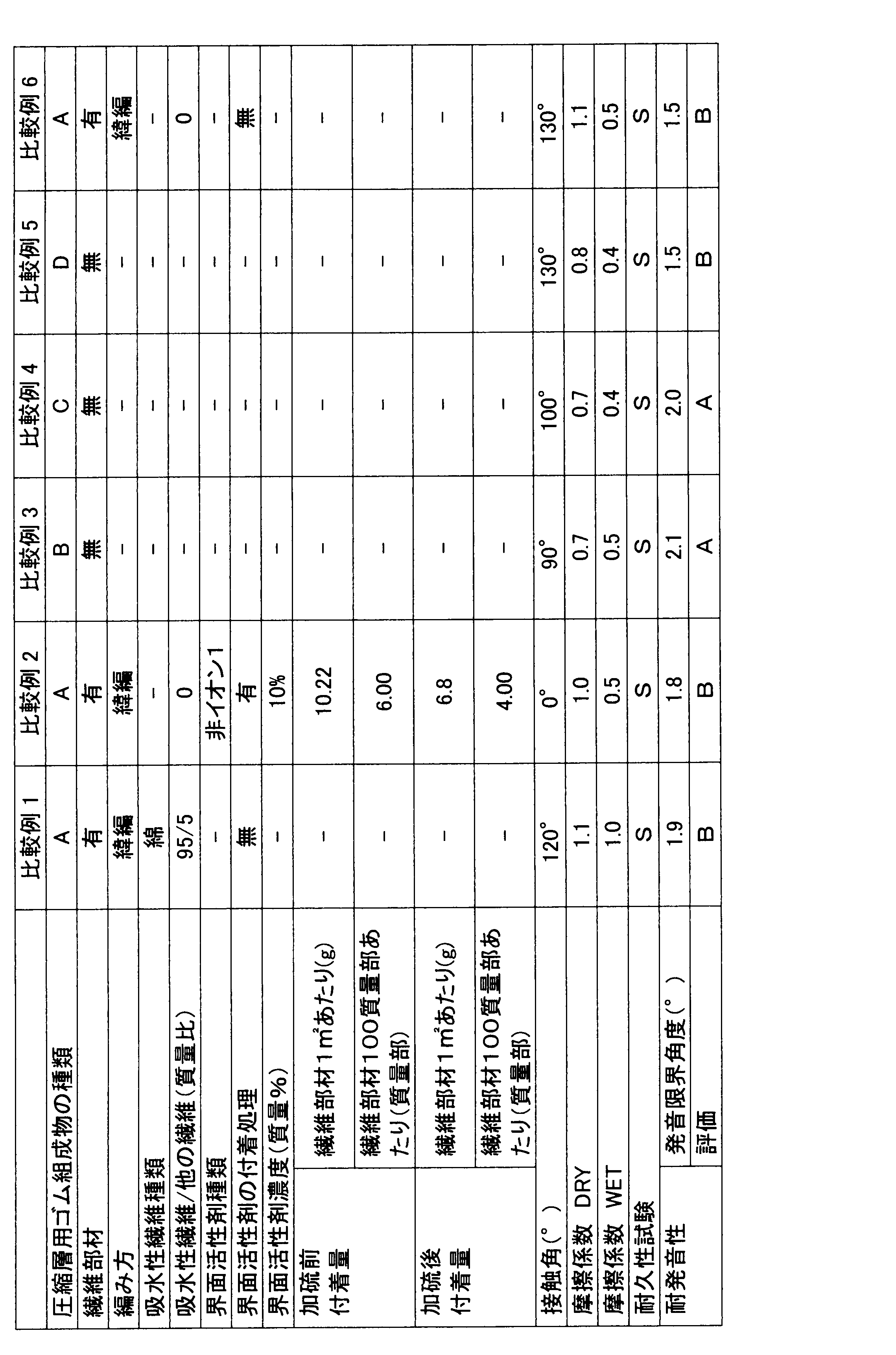
- Comparative Example 1 in which the fiber member does not contain a surfactant, the contact angle with water was as large as 120 °, and the sound was generated when the water was wet, probably because water absorption was not performed efficiently.
- Comparative Example 2 using a fiber member that contains a surfactant but does not contain a water-absorbing fiber, the contact angle with water is 0 ° and the wettability is improved. Declined and pronounced.
- Comparative Example 5 which does not contain a surfactant has a large contact angle with water of 130 ° and has poor wettability. Inefficient and pronounced when wet. Furthermore, in Comparative Example 6 using a fiber member containing neither water-absorbing fiber nor surfactant, the friction transmission surface has a larger coefficient of friction and better transmission than rubber, but wettability with water and Sounded when wet due to poor water absorption.
- the power transmission belt of the present invention can be used as a friction power transmission belt such as a flat belt, a V belt, and a V-ribbed belt. Moreover, since the transmission belt of the present invention can improve the quietness at the time of flooding, it can be suitably used for high load transmission devices used outdoors such as automobiles, motorcycles and agricultural machines.
- Transmission belt V-ribbed belt 2 ... Compressed layer 3 ... Core wire 4 ... Stretched layer 5 ... Fiber member
Landscapes
- Engineering & Computer Science (AREA)
- General Engineering & Computer Science (AREA)
- Mechanical Engineering (AREA)
- Textile Engineering (AREA)
- Treatments For Attaching Organic Compounds To Fibrous Goods (AREA)
- Yarns And Mechanical Finishing Of Yarns Or Ropes (AREA)
Abstract
Description
繊維部材は、繊維(A)で形成されており、この繊維(A)は、少なくとも吸水性繊維(吸水性繊維(A1)、繊維(A1)などということがある)を含む。
本発明の繊維部材は、伝動ベルト(摩擦伝動部を有する伝動ベルト)の摩擦伝動部(動力伝達部)の表面[すなわち、摩擦伝動面(又は動力伝達面)]を被覆するための繊維部材として有用である。そのため、本発明には、このような繊維部材を備えた伝動ベルトも含まれる。すなわち、本発明の伝動ベルトは、摩擦伝動部を有し、この摩擦伝動部の表面(摩擦伝動面)が前記繊維部材で被覆された伝動ベルトである。なお、摩擦伝動面は、プーリに接触可能な面(ベルトの腹面)である。そのため、摩擦伝動面は、繊維部材を介してプーリに接触可能となる。
圧縮層は、通常、ゴム(又はゴム組成物)で形成してもよい。ゴム(ゴム組成物を構成するゴム)としては、公知のゴム成分及び/又はエラストマー、例えば、ジエン系ゴム(天然ゴム、イソプレンゴム、ブタジエンゴム、クロロプレンゴム、スチレンブタジエンゴム(SBR)、アクリロニトリルブタジエンゴム(ニトリルゴム)、水素化ニトリルゴム(水素化ニトリルゴムと不飽和カルボン酸金属塩との混合ポリマーを含む)など)、エチレン-α-オレフィンエラストマー、クロロスルフォン化ポリエチレンゴム、アルキル化クロロスルフォン化ポリエチレンゴム、エピクロルヒドリンゴム、アクリル系ゴム、シリコーンゴム、ウレタンゴム、フッ素ゴムなどが例示できる。これらのポリマー成分は単独又は組み合わせて使用することができる。これらのポリマー成分のうち、有害なハロゲンを含まず、耐オゾン性、耐熱性、耐寒性を有し、経済性にも優れる点から、エチレン-α-オレフィンエラストマー(エチレン-プロピレンゴム(EPR)、エチレン-プロピレン-ジエンゴム(EPDMなど)などのエチレン-α-オレフィン系ゴム)が好ましい。
心線は、特に限定されず、例えば、ポリエステル繊維(ポリアルキレンアリレート系繊維)、ポリアミド繊維(アラミド繊維など)などの合成繊維、炭素繊維などの無機繊維などを含んでいてもよい。
伸張層は、圧縮層と同様のゴム組成物で形成してもよく、帆布などの布帛(補強布)で形成してもよい。
接着層は、前記の通り、必ずしも必要ではない。接着層(接着ゴム層)は、例えば、前記圧縮層(圧縮ゴム層)と同様のゴム組成物(エチレン-α-オレフィンエラストマーなどのゴム成分を含むゴム組成物)で構成できる。接着層のゴム組成物において、ゴム成分としては、前記圧縮ゴム層のゴム組成物のゴム成分と同系統又は同種のゴムを使用する場合が多い。また、加硫剤又は架橋剤、共架橋剤又は架橋助剤、加硫促進剤などの添加剤の割合も、それぞれ、前記圧縮層のゴム組成物と同様の範囲から選択できる。接着層のゴム組成物は、さらに接着性改善剤(レゾルシン-ホルムアルデヒド共縮合物、アミノ樹脂など)を含んでいてもよい。
先ず、内型として外周面に可撓性ジャケットを装着した円筒状内型を用い、外周面の可撓性ジャケットに未加硫の伸張層用シートを巻きつけ、このシート上に心線を螺旋状にスピニングし、さらに未加硫の圧縮層用シートと繊維部材とを巻き付けて積層体を作製する。次に、前記内型に装着可能な外型として、内周面に複数のリブ型が刻設された筒状外型を用い、この外型内に、前記積層体が巻き付けられた内型を、同心円状に設置する。その後、可撓性ジャケットを外型の内周面(リブ型)に向かって膨張させて積層体(圧縮層)をリブ型に圧入し、加硫する。そして、外型より内型を抜き取り、複数のリブを有する加硫ゴムスリーブを外型から脱型した後、カッターを用いて、加硫ゴムスリーブをベルト長手方向に所定の幅にカットしてVリブドベルトに仕上げる。この第1の製造方法では、伸張層、心線、圧縮層を備えた積層体を一度に膨張させて複数のリブを有するスリーブ(又はVリブドベルト)に仕上げることができる。
第1の製造方法に関連して、例えば、日本国特開2004-82702号公報に開示される方法(圧縮層のみを膨張させて予備成形体(半加硫状態)とし、次いで伸張層と心線とを膨張させて前記予備成形体に圧着し、加硫一体化してVリブドベルトに仕上げる方法)を採用してもよい。
界面活性剤による処理前後及び加硫前後において、繊維部材及びベルトの質量を測定し、以下の式から、加硫前の繊維部材1m2あたりの界面活性剤の付着量(含有量)WN(g/m2)および加硫後の繊維部材1m2あたりの界面活性剤の付着量(含有量)WR(g/m2)を求めた。
WR=(R2-R1)/SR(g/m2)
(式中、N1は付着処理前の繊維部材(繊維部材の本体)の質量、N2は付着処理後の繊維部材の質量、SNは繊維部材の面積、R1は付着処理を行わなかったベルトの加硫後の質量、R2は付着処理を行ったベルトの加硫後の質量、SRはベルトにおける繊維部材の面積を示す。)
ベルトの摩擦伝動面と水との接触角θ(水滴の端点における接線と摩擦伝動面とがなす角)は、図2に示すように、摩擦伝動面に水を滴下した水滴の投影写真から、θ/2法を用いて以下の式より求めることができる。
tanθ1=h/r → θ1=tan-1(h/r) …(2)
(式中、θ1は、摩擦伝動面に対して、水滴の端点(図2では左端点)と頂点とを結ぶ直線の角度であり、hは水滴の高さ、rは水滴の半径を示す。)
通常走行時(DRY)の摩擦係数の測定には、図3にレイアウトを示すように、直径121.6mmの駆動プーリ(Dr.)、直径76.2mmのアイドラープーリ(IDL.1)、直径61.0mmのアイドラープーリ(IDL.2)、直径76.2mmのアイドラープーリ(IDL.3)、直径77.0mmのアイドラープーリ(IDL.4)、直径121.6mmの従動プーリ(Dn.)を順に配置した試験機を用いた。
T2=180(N/6Rib)
α=π/9(rad)(式中、radはラジアンを意味する)
高温低張力逆曲げ試験は、図5にレイアウトを示すように、直径120mmの駆動プーリ(Dr.)、直径75mmのアイドラープーリ(IDL.)、直径120mmの従動プーリ(Dn.)、直径60mmのテンションプーリ(Ten.)を順に配置した試験機を用いて行なった。すなわち、試験機の各プーリにVリブドベルトを掛架し、駆動プーリの回転数を4900rpm、アイドラープーリ及びテンションプーリへのベルト巻き付け角度を90°、従動プーリ負荷を10.4kWとし、一定荷重[91kg/6Rib(リブ)]を付与してベルトを雰囲気温度120℃で走行させた。
A:300時間で1~5個の亀裂が発生
B:300時間で6個以上(平均でリブ1個あたり1個以上)の亀裂が発生
ミスアライメント発音評価試験(発音限界角度)は、図6にレイアウトを示すように、直径101mmの駆動プーリ(Dr.)、直径80mmのアイドラープーリ(IDL.1)、直径128mmのミスアライメントプーリ(W/P)、直径80mmのアイドラープーリ(IDL.2)、直径61mmのテンションプーリ(Ten.)、直径80mmのアイドラープーリ(IDL.3)を順に配置した試験機を用いて行った。また、アイドラープーリ(IDL.1)とミスアライメントプーリの軸離(スパン長)を135mmに設定し、全てのプーリが同一平面上(ミスアライメントの角度0°)に位置するように調整した。
A:発音角度が2°以上3°未満(静粛性良好)
B:発音角度が2°未満(静粛性悪い)
なお、通常、3°付近でベルトがプーリからはずれて(すなわち、リブずれとなり)正常に動力伝達しない状態になる。
表1に示すゴム組成物A~Dをバンバリーミキサーでゴム練りし、この練りゴムをカレンダーロールに通して所定厚みの未加硫圧延ゴムシート(圧縮層用シート)を作製した。
また、表1に示すゴム組成物Aを用い、上記と同様にして、伸張層用シートを作製した。
酸化亜鉛:正同化学工業(株)製、「酸化亜鉛3種」
カーボンブラック:東海カーボン(株)製、「シーストV」、平均粒子径55nm
軟化剤:パラフィン系オイル、出光興産(株)製、「NS-90」
老化防止剤:大内新興化学工業(株)製、「ノクラックMB」
有機過酸化物:日油(株)製、「パークミルD-40」
共架橋剤:大内新興化学工業(株)製、「バルノックPM」
綿短繊維:デニム、平均繊維径13μm、平均繊維長3mm
ナイロン短繊維:66ナイロン、平均繊維径27μm、平均繊維長3mm
界面活性剤:ポリオキシアルキレンアルキルエーテル、花王(株)製、「エマルゲン」
実施例1~9及び比較例1~2、6
以下に示す糸を編糸として、組織を天竺編とする緯編布(目付170g/m2、厚み0.55mm)を作製した。
第2の糸(非吸水性繊維のみからなる糸):ポリウレタン(PU)の芯糸をポリエチレンテレフタレート(PET)で被覆したカバーリング糸、太さ56dtex
なお、実施例5では、編糸として綿糸のみを用い、比較例2及び6では編糸として第2の糸のみを用いて同様に緯編布を作製した。編布(繊維部材)を構成する繊維全体に対する綿繊維(吸水性繊維)と綿繊維以外の他の繊維(非吸水性の伸縮性繊維など)の割合は、表2~4の通りである。
実施例4及び実施例7の界面活性剤に代えて、以下の非イオン性界面活性剤(以下、単に「非イオン2」という)を使用する以外、実施例4及び実施例7と同様にして繊維部材を調製した。
実施例7の界面活性剤に代えて、以下のアニオン界面活性剤(以下、単に「イオン」という)を使用する以外、実施例7と同様にして繊維部材を調製した。
実施例2の第1の糸(吸水性繊維)[ポリウレタン(PU)の芯糸を綿で被覆したカバーリング糸、太さ50番手]に代えて、他の吸水性繊維[ポリウレタン(PU)の芯糸をレーヨンで被覆したカバーリング糸(レーヨン糸)、太さ30(dtex)]を用いて緯編布を調製する以外、実施例2と同様にして繊維部材を調製した。
実施例2の第1の糸(吸水性繊維)及び第2の糸(非吸水性繊維)を用い、経編布を調製する以外、実施例2と同様にして繊維部材を調製した。なお、経編布の編組織はシングルデンビー(単層の経編布)である。
内型として外周面に可撓性ジャケットを装着した円筒状内型を用い、外周面の可撓性ジャケットに未加硫の伸張層用シートを巻きつけ、このシート上に心線を螺旋状にスピニングし、さらに表2~4に示す未加硫の圧縮層用シートおよび繊維部材(編布)をこの順に巻き付けて積層体を作製した。
本出願は、2013年6月27日出願の日本特許出願2013-135464、2014年3月25日出願の日本特許出願2014-062332及び2014年6月19日出願の日本特許出願2014-125910に基づくものであり、その内容はここに参照として取り込まれる。
2…圧縮層
3…心線
4…伸張層
5…繊維部材
Claims (18)
- 摩擦伝動部と、この摩擦伝動部の表面を被覆する繊維部材を含む伝動ベルトであって、繊維部材が、吸水性繊維(A1)を含む繊維(A)で形成され、かつ界面活性剤を含有する伝動ベルト。
- 吸水性繊維(A1)が、セルロース系繊維を含む請求項1記載の伝動ベルト。
- 吸水性繊維(A1)が、綿繊維を含む請求項1又は2記載の伝動ベルト。
- 吸水性繊維(A1)の割合が、繊維(A)全体の1質量%以上である請求項1~3のいずれかに記載の伝動ベルト。
- 繊維(A)が、さらに、非吸水性繊維(A2)を含む請求項1~4のいずれかに記載の伝動ベルト。
- 非吸水性繊維(A2)が、伸縮性繊維を含む請求項5記載の伝動ベルト。
- 吸水性繊維(A1)と非吸水性繊維(A2)との割合が、前者/後者(質量比)=99/1~5/95である請求項5又は6記載の伝動ベルト。
- 繊維部材が、編布である請求項1~7のいずれかに記載の伝動ベルト。
- 繊維部材が、緯編で編成された編布である請求項1~8のいずれかに記載の伝動ベルト。
- 界面活性剤が、非イオン性界面活性剤を含む請求項1~9のいずれかに記載の伝動ベルト。
- 界面活性剤の含有割合が、繊維部材1m2あたり1~100gである請求項1~10のいずれかに記載の伝動ベルト。
- 摩擦伝動部がゴムで形成されている請求項1~11のいずれかに記載の伝動ベルト。
- 前記伝動ベルトが、さらに、ベルト背面を形成する伸張層、この伸張層の一方の面側に形成される圧縮層、及び前記伸張層と圧縮層との間にベルト長手方向に沿って埋設される心線を含み、前記圧縮層が前記摩擦伝動部を有する請求項1~12のいずれかに記載の伝動ベルト。
- Vリブドベルトである請求項1~13のいずれかに記載の伝動ベルト。
- 摩擦伝動部の表面に水を滴下して5秒経過後の接触角が0~30°である請求項1~14のいずれかに記載の伝動ベルト。
- 伝動ベルトを構成する摩擦伝動部の表面を被覆するための繊維部材であって、吸水性繊維(A1)を含む繊維(A)で形成され、かつ界面活性剤を含有する繊維部材。
- 吸水性繊維(A1)を含む繊維(A)で形成された繊維部材の本体を、界面活性剤を含む溶液に浸漬する工程を含む、請求項16記載の繊維部材の製造方法。
- 溶液における界面活性剤の濃度が0.3~50質量%である請求項17記載の製造方法。
Priority Applications (3)
| Application Number | Priority Date | Filing Date | Title |
|---|---|---|---|
| EP14817095.4A EP3015738B1 (en) | 2013-06-27 | 2014-06-25 | Transmission belt, fiber member therefor, and manufacturing method for fiber member |
| US14/392,152 US10436285B2 (en) | 2013-06-27 | 2014-06-25 | Transmission belt, fiber member therefor, and manufacturing method for fiber member |
| CN201480037099.0A CN105358869A (zh) | 2013-06-27 | 2014-06-25 | 传动带及其纤维构件以及纤维构件的制造方法 |
Applications Claiming Priority (6)
| Application Number | Priority Date | Filing Date | Title |
|---|---|---|---|
| JP2013-135464 | 2013-06-27 | ||
| JP2013135464 | 2013-06-27 | ||
| JP2014-062332 | 2014-03-25 | ||
| JP2014062332 | 2014-03-25 | ||
| JP2014125910A JP6144234B2 (ja) | 2013-06-27 | 2014-06-19 | 伝動ベルトとその繊維部材並びに繊維部材の製造方法 |
| JP2014-125910 | 2014-06-19 |
Publications (1)
| Publication Number | Publication Date |
|---|---|
| WO2014208628A1 true WO2014208628A1 (ja) | 2014-12-31 |
Family
ID=52141955
Family Applications (1)
| Application Number | Title | Priority Date | Filing Date |
|---|---|---|---|
| PCT/JP2014/066901 Ceased WO2014208628A1 (ja) | 2013-06-27 | 2014-06-25 | 伝動ベルトとその繊維部材並びに繊維部材の製造方法 |
Country Status (5)
| Country | Link |
|---|---|
| US (1) | US10436285B2 (ja) |
| EP (1) | EP3015738B1 (ja) |
| JP (1) | JP6144234B2 (ja) |
| CN (2) | CN110219939B (ja) |
| WO (1) | WO2014208628A1 (ja) |
Cited By (3)
| Publication number | Priority date | Publication date | Assignee | Title |
|---|---|---|---|---|
| US10716912B2 (en) | 2015-03-31 | 2020-07-21 | Fisher & Paykel Healthcare Limited | User interface and system for supplying gases to an airway |
| US11300178B2 (en) | 2015-12-21 | 2022-04-12 | Mitsuboshi Belting Ltd. | Friction drive belt |
| US11324908B2 (en) | 2016-08-11 | 2022-05-10 | Fisher & Paykel Healthcare Limited | Collapsible conduit, patient interface and headgear connector |
Families Citing this family (17)
| Publication number | Priority date | Publication date | Assignee | Title |
|---|---|---|---|---|
| JP6013434B2 (ja) * | 2013-11-29 | 2016-10-25 | 三ツ星ベルト株式会社 | 摩擦伝動ベルト及びその製造方法 |
| US11326665B2 (en) | 2016-05-23 | 2022-05-10 | Mitsuboshi Belting Ltd. | Transmission belt |
| JP6740174B2 (ja) * | 2016-05-23 | 2020-08-12 | 三ツ星ベルト株式会社 | 伝動ベルト |
| JP6553687B2 (ja) * | 2016-08-29 | 2019-07-31 | 三ツ星ベルト株式会社 | Vリブドベルト及びその用途 |
| WO2018043355A1 (ja) * | 2016-08-29 | 2018-03-08 | 三ツ星ベルト株式会社 | Vリブドベルト及びその用途 |
| DE102017215654A1 (de) * | 2017-09-06 | 2019-03-07 | Contitech Antriebssysteme Gmbh | Antriebsriemen mit einer profilierten Riemenrückseite |
| JP6676725B2 (ja) * | 2017-12-07 | 2020-04-08 | 三ツ星ベルト株式会社 | 摩擦伝動ベルト、そのためのコード並びにそれらの製造方法 |
| US20190178339A1 (en) * | 2017-12-13 | 2019-06-13 | Gates Corporation | Toothed power transmission belt with back fabric |
| US11028900B2 (en) * | 2017-12-13 | 2021-06-08 | Gates Corporation | Banded friction power transmission belt |
| WO2019193881A1 (ja) * | 2018-04-04 | 2019-10-10 | バンドー化学株式会社 | 摩擦伝動ベルト |
| JP6530877B1 (ja) * | 2018-04-04 | 2019-06-12 | バンドー化学株式会社 | 摩擦伝動ベルト |
| JP6650545B1 (ja) * | 2018-08-23 | 2020-02-19 | 三ツ星ベルト株式会社 | 摩擦伝動ベルト用心線および摩擦伝動ベルトならびにそれらの製造方法 |
| JP7277350B2 (ja) * | 2018-12-26 | 2023-05-18 | 三ツ星ベルト株式会社 | 伝動用vベルト及びその製造方法 |
| JP6778315B1 (ja) * | 2019-01-28 | 2020-10-28 | 三ツ星ベルト株式会社 | Vリブドベルト及びその製造方法 |
| WO2020158629A1 (ja) | 2019-01-28 | 2020-08-06 | 三ツ星ベルト株式会社 | Vリブドベルト及びその製造方法 |
| JP6812605B1 (ja) * | 2019-06-07 | 2021-01-13 | バンドー化学株式会社 | 伝動ベルト |
| DE102021201705A1 (de) * | 2021-02-23 | 2022-08-25 | Contitech Antriebssysteme Gmbh | Keilrippenriemen |
Citations (7)
| Publication number | Priority date | Publication date | Assignee | Title |
|---|---|---|---|---|
| JP2001289284A (ja) * | 2000-04-05 | 2001-10-19 | Bando Chem Ind Ltd | 摩擦ベルト及びそれを用いたベルト式伝動装置 |
| JP2004082702A (ja) | 2002-06-28 | 2004-03-18 | Mitsuboshi Belting Ltd | 伝動ベルトの製造方法及びその方法で得られる伝動ベルト |
| JP2008185162A (ja) | 2007-01-31 | 2008-08-14 | Mitsuboshi Belting Ltd | 摩擦伝動ベルト |
| JP2009250293A (ja) * | 2008-04-03 | 2009-10-29 | Mitsuboshi Belting Ltd | Vリブドベルト |
| JP2010539394A (ja) | 2007-09-14 | 2010-12-16 | ゲイツ・ユニッタ・アジア株式会社 | Vリブドベルトおよびその製造方法 |
| JP2012045895A (ja) * | 2010-08-30 | 2012-03-08 | Mitsuboshi Belting Ltd | 積層体及びその製造方法並びに動力伝動用ベルト |
| JP2013096488A (ja) * | 2011-10-31 | 2013-05-20 | Mitsuboshi Belting Ltd | 摩擦伝動ベルトの製造方法、摩擦伝動ベルト、及び摩擦伝動ベルトの製造装置 |
Family Cites Families (14)
| Publication number | Priority date | Publication date | Assignee | Title |
|---|---|---|---|---|
| EP0451983B1 (en) * | 1990-03-29 | 1995-12-13 | Mitsuboshi Belting Ltd. | Power transmission belt |
| US6294600B1 (en) * | 1998-06-03 | 2001-09-25 | Mitsuboshi Belting, Ltd. | Rubber composition and power transmission belt incorporating the rubber composition |
| JP2003014052A (ja) | 2000-06-22 | 2003-01-15 | Mitsuboshi Belting Ltd | 動力伝動用ベルト |
| US6821370B2 (en) * | 2001-11-13 | 2004-11-23 | Kimberly-Clark Worldwide, Inc. | Method for positioning garment side panels |
| JP4672603B2 (ja) * | 2005-08-31 | 2011-04-20 | 三ツ星ベルト株式会社 | 摩擦伝動ベルト |
| US8197372B2 (en) * | 2006-04-07 | 2012-06-12 | The Gates Corporation | Power transmission belt |
| CN101138706A (zh) * | 2006-09-04 | 2008-03-12 | 胡萍 | 一种束状中空纤维膜及其制备方法 |
| JP5295548B2 (ja) * | 2006-12-01 | 2013-09-18 | 花王株式会社 | 床水拭き用助剤 |
| JP5058886B2 (ja) * | 2007-12-18 | 2012-10-24 | 三ツ星ベルト株式会社 | 摩擦伝動ベルト |
| JP2013020085A (ja) * | 2011-07-11 | 2013-01-31 | Canon Inc | 現像剤層規制部材及び現像装置 |
| JP5771162B2 (ja) * | 2012-03-09 | 2015-08-26 | 三ツ星ベルト株式会社 | 摩擦伝動ベルト及びその製造方法 |
| JP6059111B2 (ja) * | 2012-10-31 | 2017-01-11 | 三ツ星ベルト株式会社 | 摩擦伝動ベルト |
| KR20150095644A (ko) * | 2012-12-13 | 2015-08-21 | 반도 카가쿠 가부시키가이샤 | 전동벨트 |
| JP6023736B2 (ja) * | 2013-03-29 | 2016-11-09 | 三ツ星ベルト株式会社 | Vリブドベルト |
-
2014
- 2014-06-19 JP JP2014125910A patent/JP6144234B2/ja active Active
- 2014-06-25 CN CN201910342904.5A patent/CN110219939B/zh active Active
- 2014-06-25 EP EP14817095.4A patent/EP3015738B1/en active Active
- 2014-06-25 CN CN201480037099.0A patent/CN105358869A/zh active Pending
- 2014-06-25 WO PCT/JP2014/066901 patent/WO2014208628A1/ja not_active Ceased
- 2014-06-25 US US14/392,152 patent/US10436285B2/en active Active
Patent Citations (7)
| Publication number | Priority date | Publication date | Assignee | Title |
|---|---|---|---|---|
| JP2001289284A (ja) * | 2000-04-05 | 2001-10-19 | Bando Chem Ind Ltd | 摩擦ベルト及びそれを用いたベルト式伝動装置 |
| JP2004082702A (ja) | 2002-06-28 | 2004-03-18 | Mitsuboshi Belting Ltd | 伝動ベルトの製造方法及びその方法で得られる伝動ベルト |
| JP2008185162A (ja) | 2007-01-31 | 2008-08-14 | Mitsuboshi Belting Ltd | 摩擦伝動ベルト |
| JP2010539394A (ja) | 2007-09-14 | 2010-12-16 | ゲイツ・ユニッタ・アジア株式会社 | Vリブドベルトおよびその製造方法 |
| JP2009250293A (ja) * | 2008-04-03 | 2009-10-29 | Mitsuboshi Belting Ltd | Vリブドベルト |
| JP2012045895A (ja) * | 2010-08-30 | 2012-03-08 | Mitsuboshi Belting Ltd | 積層体及びその製造方法並びに動力伝動用ベルト |
| JP2013096488A (ja) * | 2011-10-31 | 2013-05-20 | Mitsuboshi Belting Ltd | 摩擦伝動ベルトの製造方法、摩擦伝動ベルト、及び摩擦伝動ベルトの製造装置 |
Non-Patent Citations (1)
| Title |
|---|
| See also references of EP3015738A4 |
Cited By (6)
| Publication number | Priority date | Publication date | Assignee | Title |
|---|---|---|---|---|
| US10716912B2 (en) | 2015-03-31 | 2020-07-21 | Fisher & Paykel Healthcare Limited | User interface and system for supplying gases to an airway |
| US11904097B2 (en) | 2015-03-31 | 2024-02-20 | Fisher & Paykel Healthcare Limited | User interface and system for supplying gases to an airway |
| US12171946B2 (en) | 2015-03-31 | 2024-12-24 | Fisher & Paykel Healthcare Limited | User interface and system for supplying gases to an airway |
| US12527934B2 (en) | 2015-03-31 | 2026-01-20 | Fisher & Paykel Healthcare Limited | User interface and system for supplying gases to an airway |
| US11300178B2 (en) | 2015-12-21 | 2022-04-12 | Mitsuboshi Belting Ltd. | Friction drive belt |
| US11324908B2 (en) | 2016-08-11 | 2022-05-10 | Fisher & Paykel Healthcare Limited | Collapsible conduit, patient interface and headgear connector |
Also Published As
| Publication number | Publication date |
|---|---|
| CN110219939B (zh) | 2021-07-30 |
| CN105358869A (zh) | 2016-02-24 |
| US20160273616A1 (en) | 2016-09-22 |
| CN110219939A (zh) | 2019-09-10 |
| EP3015738A4 (en) | 2017-02-01 |
| JP2015194239A (ja) | 2015-11-05 |
| EP3015738B1 (en) | 2025-04-23 |
| JP6144234B2 (ja) | 2017-06-07 |
| US10436285B2 (en) | 2019-10-08 |
| EP3015738A1 (en) | 2016-05-04 |
Similar Documents
| Publication | Publication Date | Title |
|---|---|---|
| JP6144234B2 (ja) | 伝動ベルトとその繊維部材並びに繊維部材の製造方法 | |
| JP6013434B2 (ja) | 摩擦伝動ベルト及びその製造方法 | |
| JP6023736B2 (ja) | Vリブドベルト | |
| JP6059111B2 (ja) | 摩擦伝動ベルト | |
| JP5997712B2 (ja) | 摩擦伝動ベルト | |
| JP6527433B2 (ja) | 摩擦伝動ベルト及びその製造方法 | |
| JP6198354B2 (ja) | Vリブドベルト | |
| JP6748133B2 (ja) | 摩擦伝動ベルト及びその製造方法 | |
| EP3505792B1 (en) | V-ribbed belt and use thereof | |
| TW201932733A (zh) | 摩擦傳動帶及其製造方法 | |
| JP2017150662A (ja) | 摩擦伝動ベルト及びその製造方法 | |
| JP2007298162A (ja) | 摩擦伝動ベルト | |
| WO2016047781A1 (ja) | 摩擦伝動ベルト及びその製造方法 | |
| WO2018174093A1 (ja) | 摩擦伝動ベルト及びその製造方法 | |
| JP2005240925A (ja) | 動力伝動ベルト | |
| JP2008157319A (ja) | 摩擦伝動ベルト | |
| JP2013130246A (ja) | 摩擦伝動ベルト及びその製造方法 |
Legal Events
| Date | Code | Title | Description |
|---|---|---|---|
| WWE | Wipo information: entry into national phase |
Ref document number: 201480037099.0 Country of ref document: CN |
|
| 121 | Ep: the epo has been informed by wipo that ep was designated in this application |
Ref document number: 14817095 Country of ref document: EP Kind code of ref document: A1 |
|
| WWE | Wipo information: entry into national phase |
Ref document number: 2014817095 Country of ref document: EP |
|
| WWE | Wipo information: entry into national phase |
Ref document number: 14392152 Country of ref document: US |
|
| NENP | Non-entry into the national phase |
Ref country code: DE |
|
| WWG | Wipo information: grant in national office |
Ref document number: 2014817095 Country of ref document: EP |