WO2015001621A1 - ハイブリッド駆動システム - Google Patents
ハイブリッド駆動システム Download PDFInfo
- Publication number
- WO2015001621A1 WO2015001621A1 PCT/JP2013/068176 JP2013068176W WO2015001621A1 WO 2015001621 A1 WO2015001621 A1 WO 2015001621A1 JP 2013068176 W JP2013068176 W JP 2013068176W WO 2015001621 A1 WO2015001621 A1 WO 2015001621A1
- Authority
- WO
- WIPO (PCT)
- Prior art keywords
- power
- group
- power supply
- power storage
- storage device
- Prior art date
- Legal status (The legal status is an assumption and is not a legal conclusion. Google has not performed a legal analysis and makes no representation as to the accuracy of the status listed.)
- Ceased
Links
Images


Classifications
-
- B—PERFORMING OPERATIONS; TRANSPORTING
- B60—VEHICLES IN GENERAL
- B60L—PROPULSION OF ELECTRICALLY-PROPELLED VEHICLES; SUPPLYING ELECTRIC POWER FOR AUXILIARY EQUIPMENT OF ELECTRICALLY-PROPELLED VEHICLES; ELECTRODYNAMIC BRAKE SYSTEMS FOR VEHICLES IN GENERAL; MAGNETIC SUSPENSION OR LEVITATION FOR VEHICLES; MONITORING OPERATING VARIABLES OF ELECTRICALLY-PROPELLED VEHICLES; ELECTRIC SAFETY DEVICES FOR ELECTRICALLY-PROPELLED VEHICLES
- B60L3/00—Electric devices on electrically-propelled vehicles for safety purposes; Monitoring operating variables, e.g. speed, deceleration or energy consumption
- B60L3/0023—Detecting, eliminating, remedying or compensating for drive train abnormalities, e.g. failures within the drive train
- B60L3/0046—Detecting, eliminating, remedying or compensating for drive train abnormalities, e.g. failures within the drive train relating to electric energy storage systems, e.g. batteries or capacitors
-
- B—PERFORMING OPERATIONS; TRANSPORTING
- B60—VEHICLES IN GENERAL
- B60L—PROPULSION OF ELECTRICALLY-PROPELLED VEHICLES; SUPPLYING ELECTRIC POWER FOR AUXILIARY EQUIPMENT OF ELECTRICALLY-PROPELLED VEHICLES; ELECTRODYNAMIC BRAKE SYSTEMS FOR VEHICLES IN GENERAL; MAGNETIC SUSPENSION OR LEVITATION FOR VEHICLES; MONITORING OPERATING VARIABLES OF ELECTRICALLY-PROPELLED VEHICLES; ELECTRIC SAFETY DEVICES FOR ELECTRICALLY-PROPELLED VEHICLES
- B60L3/00—Electric devices on electrically-propelled vehicles for safety purposes; Monitoring operating variables, e.g. speed, deceleration or energy consumption
-
- B—PERFORMING OPERATIONS; TRANSPORTING
- B60—VEHICLES IN GENERAL
- B60L—PROPULSION OF ELECTRICALLY-PROPELLED VEHICLES; SUPPLYING ELECTRIC POWER FOR AUXILIARY EQUIPMENT OF ELECTRICALLY-PROPELLED VEHICLES; ELECTRODYNAMIC BRAKE SYSTEMS FOR VEHICLES IN GENERAL; MAGNETIC SUSPENSION OR LEVITATION FOR VEHICLES; MONITORING OPERATING VARIABLES OF ELECTRICALLY-PROPELLED VEHICLES; ELECTRIC SAFETY DEVICES FOR ELECTRICALLY-PROPELLED VEHICLES
- B60L50/00—Electric propulsion with power supplied within the vehicle
- B60L50/10—Electric propulsion with power supplied within the vehicle using propulsion power supplied by engine-driven generators, e.g. generators driven by combustion engines
- B60L50/15—Electric propulsion with power supplied within the vehicle using propulsion power supplied by engine-driven generators, e.g. generators driven by combustion engines with additional electric power supply
-
- B—PERFORMING OPERATIONS; TRANSPORTING
- B60—VEHICLES IN GENERAL
- B60L—PROPULSION OF ELECTRICALLY-PROPELLED VEHICLES; SUPPLYING ELECTRIC POWER FOR AUXILIARY EQUIPMENT OF ELECTRICALLY-PROPELLED VEHICLES; ELECTRODYNAMIC BRAKE SYSTEMS FOR VEHICLES IN GENERAL; MAGNETIC SUSPENSION OR LEVITATION FOR VEHICLES; MONITORING OPERATING VARIABLES OF ELECTRICALLY-PROPELLED VEHICLES; ELECTRIC SAFETY DEVICES FOR ELECTRICALLY-PROPELLED VEHICLES
- B60L50/00—Electric propulsion with power supplied within the vehicle
- B60L50/50—Electric propulsion with power supplied within the vehicle using propulsion power supplied by batteries or fuel cells
- B60L50/51—Electric propulsion with power supplied within the vehicle using propulsion power supplied by batteries or fuel cells characterised by AC-motors
-
- B—PERFORMING OPERATIONS; TRANSPORTING
- B60—VEHICLES IN GENERAL
- B60L—PROPULSION OF ELECTRICALLY-PROPELLED VEHICLES; SUPPLYING ELECTRIC POWER FOR AUXILIARY EQUIPMENT OF ELECTRICALLY-PROPELLED VEHICLES; ELECTRODYNAMIC BRAKE SYSTEMS FOR VEHICLES IN GENERAL; MAGNETIC SUSPENSION OR LEVITATION FOR VEHICLES; MONITORING OPERATING VARIABLES OF ELECTRICALLY-PROPELLED VEHICLES; ELECTRIC SAFETY DEVICES FOR ELECTRICALLY-PROPELLED VEHICLES
- B60L50/00—Electric propulsion with power supplied within the vehicle
- B60L50/50—Electric propulsion with power supplied within the vehicle using propulsion power supplied by batteries or fuel cells
- B60L50/53—Electric propulsion with power supplied within the vehicle using propulsion power supplied by batteries or fuel cells in combination with an external power supply, e.g. from overhead contact lines
-
- B—PERFORMING OPERATIONS; TRANSPORTING
- B60—VEHICLES IN GENERAL
- B60L—PROPULSION OF ELECTRICALLY-PROPELLED VEHICLES; SUPPLYING ELECTRIC POWER FOR AUXILIARY EQUIPMENT OF ELECTRICALLY-PROPELLED VEHICLES; ELECTRODYNAMIC BRAKE SYSTEMS FOR VEHICLES IN GENERAL; MAGNETIC SUSPENSION OR LEVITATION FOR VEHICLES; MONITORING OPERATING VARIABLES OF ELECTRICALLY-PROPELLED VEHICLES; ELECTRIC SAFETY DEVICES FOR ELECTRICALLY-PROPELLED VEHICLES
- B60L9/00—Electric propulsion with power supply external to the vehicle
- B60L9/16—Electric propulsion with power supply external to the vehicle using AC induction motors
- B60L9/18—Electric propulsion with power supply external to the vehicle using AC induction motors fed from DC supply lines
- B60L9/22—Electric propulsion with power supply external to the vehicle using AC induction motors fed from DC supply lines polyphase motors
-
- B—PERFORMING OPERATIONS; TRANSPORTING
- B60—VEHICLES IN GENERAL
- B60L—PROPULSION OF ELECTRICALLY-PROPELLED VEHICLES; SUPPLYING ELECTRIC POWER FOR AUXILIARY EQUIPMENT OF ELECTRICALLY-PROPELLED VEHICLES; ELECTRODYNAMIC BRAKE SYSTEMS FOR VEHICLES IN GENERAL; MAGNETIC SUSPENSION OR LEVITATION FOR VEHICLES; MONITORING OPERATING VARIABLES OF ELECTRICALLY-PROPELLED VEHICLES; ELECTRIC SAFETY DEVICES FOR ELECTRICALLY-PROPELLED VEHICLES
- B60L9/00—Electric propulsion with power supply external to the vehicle
- B60L9/16—Electric propulsion with power supply external to the vehicle using AC induction motors
- B60L9/24—Electric propulsion with power supply external to the vehicle using AC induction motors fed from AC supply lines
- B60L9/28—Electric propulsion with power supply external to the vehicle using AC induction motors fed from AC supply lines polyphase motors
-
- B—PERFORMING OPERATIONS; TRANSPORTING
- B60—VEHICLES IN GENERAL
- B60W—CONJOINT CONTROL OF VEHICLE SUB-UNITS OF DIFFERENT TYPE OR DIFFERENT FUNCTION; CONTROL SYSTEMS SPECIALLY ADAPTED FOR HYBRID VEHICLES; ROAD VEHICLE DRIVE CONTROL SYSTEMS FOR PURPOSES NOT RELATED TO THE CONTROL OF A PARTICULAR SUB-UNIT
- B60W10/00—Conjoint control of vehicle sub-units of different type or different function
- B60W10/04—Conjoint control of vehicle sub-units of different type or different function including control of propulsion units
- B60W10/08—Conjoint control of vehicle sub-units of different type or different function including control of propulsion units including control of electric propulsion units, e.g. motors or generators
-
- B—PERFORMING OPERATIONS; TRANSPORTING
- B60—VEHICLES IN GENERAL
- B60W—CONJOINT CONTROL OF VEHICLE SUB-UNITS OF DIFFERENT TYPE OR DIFFERENT FUNCTION; CONTROL SYSTEMS SPECIALLY ADAPTED FOR HYBRID VEHICLES; ROAD VEHICLE DRIVE CONTROL SYSTEMS FOR PURPOSES NOT RELATED TO THE CONTROL OF A PARTICULAR SUB-UNIT
- B60W10/00—Conjoint control of vehicle sub-units of different type or different function
- B60W10/24—Conjoint control of vehicle sub-units of different type or different function including control of energy storage means
- B60W10/26—Conjoint control of vehicle sub-units of different type or different function including control of energy storage means for electrical energy, e.g. batteries or capacitors
-
- B—PERFORMING OPERATIONS; TRANSPORTING
- B60—VEHICLES IN GENERAL
- B60W—CONJOINT CONTROL OF VEHICLE SUB-UNITS OF DIFFERENT TYPE OR DIFFERENT FUNCTION; CONTROL SYSTEMS SPECIALLY ADAPTED FOR HYBRID VEHICLES; ROAD VEHICLE DRIVE CONTROL SYSTEMS FOR PURPOSES NOT RELATED TO THE CONTROL OF A PARTICULAR SUB-UNIT
- B60W20/00—Control systems specially adapted for hybrid vehicles
-
- B—PERFORMING OPERATIONS; TRANSPORTING
- B61—RAILWAYS
- B61C—LOCOMOTIVES; MOTOR RAILCARS
- B61C3/00—Electric locomotives or railcars
-
- B—PERFORMING OPERATIONS; TRANSPORTING
- B61—RAILWAYS
- B61C—LOCOMOTIVES; MOTOR RAILCARS
- B61C5/00—Locomotives or motor railcars with IC engines or gas turbines
-
- H—ELECTRICITY
- H02—GENERATION; CONVERSION OR DISTRIBUTION OF ELECTRIC POWER
- H02J—ELECTRIC POWER NETWORKS; CIRCUIT ARRANGEMENTS OR SYSTEMS FOR SUPPLYING OR DISTRIBUTING ELECTRIC POWER; SYSTEMS FOR STORING ELECTRIC ENERGY
- H02J1/00—Circuit arrangements for DC mains or DC distribution networks
- H02J1/10—Parallel operation of DC sources
-
- H—ELECTRICITY
- H02—GENERATION; CONVERSION OR DISTRIBUTION OF ELECTRIC POWER
- H02J—ELECTRIC POWER NETWORKS; CIRCUIT ARRANGEMENTS OR SYSTEMS FOR SUPPLYING OR DISTRIBUTING ELECTRIC POWER; SYSTEMS FOR STORING ELECTRIC ENERGY
- H02J7/00—Circuit arrangements for charging or discharging batteries or for supplying loads from batteries
- H02J7/34—Parallel operation in networks using both storage and other DC sources, e.g. providing buffering
-
- B—PERFORMING OPERATIONS; TRANSPORTING
- B60—VEHICLES IN GENERAL
- B60L—PROPULSION OF ELECTRICALLY-PROPELLED VEHICLES; SUPPLYING ELECTRIC POWER FOR AUXILIARY EQUIPMENT OF ELECTRICALLY-PROPELLED VEHICLES; ELECTRODYNAMIC BRAKE SYSTEMS FOR VEHICLES IN GENERAL; MAGNETIC SUSPENSION OR LEVITATION FOR VEHICLES; MONITORING OPERATING VARIABLES OF ELECTRICALLY-PROPELLED VEHICLES; ELECTRIC SAFETY DEVICES FOR ELECTRICALLY-PROPELLED VEHICLES
- B60L2200/00—Type of vehicles
- B60L2200/26—Rail vehicles
-
- H—ELECTRICITY
- H02—GENERATION; CONVERSION OR DISTRIBUTION OF ELECTRIC POWER
- H02J—ELECTRIC POWER NETWORKS; CIRCUIT ARRANGEMENTS OR SYSTEMS FOR SUPPLYING OR DISTRIBUTING ELECTRIC POWER; SYSTEMS FOR STORING ELECTRIC ENERGY
- H02J2101/00—Supply or distribution of decentralised, dispersed or local electric power generation
- H02J2101/20—Dispersed power generation using renewable energy sources
- H02J2101/30—Fuel cells
-
- H—ELECTRICITY
- H02—GENERATION; CONVERSION OR DISTRIBUTION OF ELECTRIC POWER
- H02J—ELECTRIC POWER NETWORKS; CIRCUIT ARRANGEMENTS OR SYSTEMS FOR SUPPLYING OR DISTRIBUTING ELECTRIC POWER; SYSTEMS FOR STORING ELECTRIC ENERGY
- H02J2105/00—Networks for supplying or distributing electric power characterised by their spatial reach or by the load
- H02J2105/30—Networks for supplying or distributing electric power characterised by their spatial reach or by the load the load networks being external to vehicles, i.e. exchanging power with vehicles
- H02J2105/33—Networks for supplying or distributing electric power characterised by their spatial reach or by the load the load networks being external to vehicles, i.e. exchanging power with vehicles exchanging power with road vehicles
- H02J2105/37—Networks for supplying or distributing electric power characterised by their spatial reach or by the load the load networks being external to vehicles, i.e. exchanging power with vehicles exchanging power with road vehicles exchanging power with electric vehicles [EV] or with hybrid electric vehicles [HEV]
-
- H—ELECTRICITY
- H02—GENERATION; CONVERSION OR DISTRIBUTION OF ELECTRIC POWER
- H02J—ELECTRIC POWER NETWORKS; CIRCUIT ARRANGEMENTS OR SYSTEMS FOR SUPPLYING OR DISTRIBUTING ELECTRIC POWER; SYSTEMS FOR STORING ELECTRIC ENERGY
- H02J7/00—Circuit arrangements for charging or discharging batteries or for supplying loads from batteries
- H02J7/14—Circuit arrangements for charging or discharging batteries or for supplying loads from batteries for charging batteries from dynamo-electric generators driven at varying speed, e.g. on vehicle
- H02J7/1423—Circuit arrangements for charging or discharging batteries or for supplying loads from batteries for charging batteries from dynamo-electric generators driven at varying speed, e.g. on vehicle with multiple batteries
-
- Y—GENERAL TAGGING OF NEW TECHNOLOGICAL DEVELOPMENTS; GENERAL TAGGING OF CROSS-SECTIONAL TECHNOLOGIES SPANNING OVER SEVERAL SECTIONS OF THE IPC; TECHNICAL SUBJECTS COVERED BY FORMER USPC CROSS-REFERENCE ART COLLECTIONS [XRACs] AND DIGESTS
- Y02—TECHNOLOGIES OR APPLICATIONS FOR MITIGATION OR ADAPTATION AGAINST CLIMATE CHANGE
- Y02T—CLIMATE CHANGE MITIGATION TECHNOLOGIES RELATED TO TRANSPORTATION
- Y02T10/00—Road transport of goods or passengers
- Y02T10/60—Other road transportation technologies with climate change mitigation effect
- Y02T10/70—Energy storage systems for electromobility, e.g. batteries
-
- Y—GENERAL TAGGING OF NEW TECHNOLOGICAL DEVELOPMENTS; GENERAL TAGGING OF CROSS-SECTIONAL TECHNOLOGIES SPANNING OVER SEVERAL SECTIONS OF THE IPC; TECHNICAL SUBJECTS COVERED BY FORMER USPC CROSS-REFERENCE ART COLLECTIONS [XRACs] AND DIGESTS
- Y02—TECHNOLOGIES OR APPLICATIONS FOR MITIGATION OR ADAPTATION AGAINST CLIMATE CHANGE
- Y02T—CLIMATE CHANGE MITIGATION TECHNOLOGIES RELATED TO TRANSPORTATION
- Y02T10/00—Road transport of goods or passengers
- Y02T10/60—Other road transportation technologies with climate change mitigation effect
- Y02T10/7072—Electromobility specific charging systems or methods for batteries, ultracapacitors, supercapacitors or double-layer capacitors
-
- Y—GENERAL TAGGING OF NEW TECHNOLOGICAL DEVELOPMENTS; GENERAL TAGGING OF CROSS-SECTIONAL TECHNOLOGIES SPANNING OVER SEVERAL SECTIONS OF THE IPC; TECHNICAL SUBJECTS COVERED BY FORMER USPC CROSS-REFERENCE ART COLLECTIONS [XRACs] AND DIGESTS
- Y10—TECHNICAL SUBJECTS COVERED BY FORMER USPC
- Y10S—TECHNICAL SUBJECTS COVERED BY FORMER USPC CROSS-REFERENCE ART COLLECTIONS [XRACs] AND DIGESTS
- Y10S903/00—Hybrid electric vehicles, HEVS
- Y10S903/902—Prime movers comprising electrical and internal combustion motors
- Y10S903/903—Prime movers comprising electrical and internal combustion motors having energy storing means, e.g. battery, capacitor
- Y10S903/93—Conjoint control of different elements
Definitions
- the present invention relates to a hybrid drive system.
- a power supply device that generates DC power and a power storage device that is connected in parallel with the output of the power supply device to supply and store DC power
- a plurality of sets of power supply sources composed of a power storage device and the plurality of sets of power supply sources are connected to an inverter device that is individually supplied with power at a DC output section via a switch that can be opened and closed.
- the present invention has been made in view of the above, and an object of the present invention is to provide a hybrid drive system that can effectively utilize a power storage device provided on the side of a power supply device in which a problem has occurred.
- the present invention is connected to first and second power supply devices that supply DC power, and to each of the first and second power supply devices.
- the first and second power storage devices that store or release; the first load device that drives the first load by receiving DC power from the first power supply device and the first power storage device; And a second load device that receives a supply of DC power from the second power supply device and the second power storage device to drive a second load, the hybrid drive system comprising the first power storage device And an inter-group contactor for electrically opening and closing between the input terminals of the second power storage device.
- FIG. 1 is a diagram illustrating a configuration example of the hybrid drive system according to the first embodiment.
- FIG. 2 is a diagram illustrating a configuration example of the power supply device.
- FIG. 3 is a diagram illustrating a configuration example of the load device.
- FIG. 4 is a diagram illustrating an arrangement example of the inter-group contactors different from that in FIG. 1.
- FIG. 5 is a flowchart showing a determination flow of whether or not to close the inter-group contactor.
- FIG. 6 is a diagram illustrating a configuration example of a hybrid drive system according to the second embodiment.
- FIG. 7 is a diagram illustrating a configuration example of a hybrid drive system according to the third embodiment.
- FIG. 8 is a diagram illustrating a configuration example of a hybrid drive system according to the fourth embodiment.
- FIG. 1 is a diagram illustrating a configuration example of the hybrid drive system according to the first embodiment.
- the hybrid drive system according to the first embodiment receives DC power from a DC overhead line 1 via a pantograph 2 (2a, 2b), and receives the received DC power via an overhead line breaker 3.
- 11 and the power supply device 21 are supplied (applied).
- the negative sides of the power supply device 11 and the power supply device 21 are in contact with the rail via the wheels 4 (4a, 4b), respectively.
- the hybrid drive system is composed of two hybrid systems as shown in FIG.
- the first group of hybrid systems includes a power supply device 11 that is a first power supply device, a load device 12 that is a first load device, and a power storage device 13 that is a first power storage device, and a second group of hybrid systems. Includes a power supply device 21 that is a second power supply device, a load device 22 that is a second load device, and a power storage device 23 that is a second power storage device.
- the control unit 200 performs overall control of the first and second group hybrid systems, that is, the entire hybrid drive system.
- a contactor (hereinafter referred to as “intergroup contactor”) 100 for electrically connecting / opening the systems is provided between the first group and the second group of hybrid systems.
- a contactor 14a that is a first contactor for the first power supply device, and for the first power supply device
- a second contactor 14b and a first power supply charging resistor 14c connected in parallel to the contactor 14b are provided on the input side of the power supply 11, and are used for the first power storage device.
- Circuit breaker 16, contactor 17a which is the first contactor for the first power storage device, contactor 17b which is the second contactor for the first power storage device, and this contactor 17b are connected in parallel.
- the charging resistor 17c for the second power storage device and the fuse 15 as an overcurrent protection element in the first power storage device are configured.
- the second power supply device a contactor 24a, a contactor 24b, and a charging resistor 24c connected in parallel to the contactor 24b are provided on the input side of the power supply device 12.
- the second power storage device includes a fuse 25, a circuit breaker 26, a contactor 27a, a contactor 27b, and a charging resistor 27c connected in parallel to the contactor 27b.
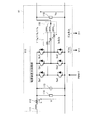
- FIG. 2 is a diagram illustrating a configuration example of the power supply device 11.
- the power supply device 11 operates as a DC-DC converter that converts the voltage of the DC power supplied from the DC overhead wire 1 into a DC voltage suitable for the load device 12 and the power storage device 13 connected to the output side.
- a step-down DCDC converter that converts the voltage of the input DC power into a lower voltage is shown as an example, but the present invention is not limited to this configuration.
- the power supply device 11 includes a filter reactor 111 that suppresses an inrush current at the time of an abnormal failure, an input current measuring unit 112 that measures an input current (Ii), a filter capacitor 113 that accumulates DC power, and An input voltage measuring unit 114 that measures an input voltage (Vi), a power supply main circuit unit 115 that performs a switching operation, an output reactor 116 for power conversion control, and an output current measurement that measures an output current (Ia, Ib, Ic) Unit 117 (117a, 117b, 117c) and an output voltage measuring unit 118 that measures the output voltage (Vo).
- the control unit 200 performs arithmetic processing based on the above-described current information I11, I21 (Ii, Ia, Ib, Ic), voltage information V11, V21 (Vi, Vo), and the like, and is included in the power supply main circuit unit 115.
- a PWM (Pulse Width Modulation) control signal PWM11, PWM21
- the power supply device 11 functions as a DCDC converter.
- three-phase three-multiplex configuration is described as the power supply main circuit unit 115 and the output reactor 116.
- the switching timing of each phase of the power supply main circuit unit 115 can be appropriately shifted. That is, the three-phase configuration reduces the amplitude of the current ripple of the three-phase composite output that is the output of the power supply device 11 by shifting the generation timing of the current ripple of each phase, thereby reducing the harmonics of the output current, Or it is the structure for aiming at size reduction of a reactor.
- a single phase may be used, and the function as a DCDC converter is not lost.
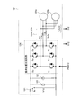
- FIG. 3 is a diagram illustrating a configuration example of the load device 12, which is a configuration example of obtaining driving force for propelling the vehicle by converting the input DC power voltage into AC power voltage.
- the load device 12 includes an input current measuring unit 121 that measures an input current (Is), a filter capacitor 122 that suppresses pulsation of a DC input voltage, and a load input voltage measuring unit that measures an input load voltage.
- Is input current
- a load device main circuit unit 124 that is a semiconductor switch circuit for so-called inverter operation for converting a DC voltage into an AC voltage
- a load output current measuring unit 125 125a, 125a, 125
- AC motors 126a and 126b that obtain driving force from AC power supplied from the load device main circuit unit 124.
- the current information I12 (Is, Iu, Iv) measured by the load input current measuring unit 121 and the load output current measuring unit 125 and the voltage information V12 measured by the load input voltage measuring unit 123 are input to the control unit 200.
- the load device 22 performs the same measurement, and the measured current information I22 (Is, Iu, Iv) and voltage information V22 (V12) are input to the control unit 200.
- control unit 200 performs arithmetic processing based on the above-described current information I12, I22 (Is, Iu, Iv), voltage information V12, V22, and the like, and a semiconductor included in the load device main circuit unit 125. Processing for generating PWM control signals (PWM12, PWM22) for ON / OFF control of the switches (Su, Sv, Sw, Sx, Sy, Sz) is performed. With this control, the load device main circuit unit 124 functions as a so-called inverter.
- switchgear such as circuit breakers and contactors
- the contactor 14a is closed when the power supply device 11 is operated, and is opened in the case where some abnormality occurs in the power supply device 11 and the operation is stopped immediately when the power supply device 11 is not operated. That is, the contactor 14 a is a contactor for controlling opening and closing between the power supply device 11 and the DC overhead wire 1.
- the charging resistor 14c is provided, charging is performed while maintaining an appropriate charging current value, and when the charging is completed, the contactor 14b is closed and both ends of the charging resistor 14c are short-circuited. On the other hand, during the subsequent normal operation, the contactor 14b is kept closed so that power is not consumed by the charging resistor 14c.
- the fuse 15 is provided in order to prevent an overcurrent from flowing due to an abnormality occurring in the circuit breaker 16, the load device main circuit portion 124, and the like.
- the circuit breaker 16 is a high-speed circuit breaker similar to the overhead line circuit breaker 3 as a single unit, but is provided mainly to block overcurrent caused by the power storage device 13.
- the contactor 17a, the contactor 17b, and the charging resistor 17c have the same functions as the contactor 14a, the contactor 14b, and the charging resistor 14c, respectively. It is a contactor for connecting or releasing between.
- the charging resistor 17c is a charging resistor for limiting an appropriate charging current in order to charge the filter capacitor 122 (see FIG. 3) provided at the input of the load device 12.
- the contactor 17 b is a contactor for short-circuiting the charging resistor 17 c after completing the charging of the filter capacitor 122 so as not to generate an input loss when the load device 12 is driven. While the power storage device 13 is safely connected to the load device 12 or the power supply device 11 by these load device circuit breakers, contactors, etc., when the power storage device 13 is not in use or when an abnormality occurs, the power storage device 13 is quickly stored. The device 13 can be opened.
- control unit 200 When the control unit 200 outputs a control signal to the load device main circuit unit 124 to perform drive control on the AC motors 126a and 126b, the control unit 200 controls the power source device main circuit unit 115 to control drive on the AC motors 126a and 126b. In addition to performing power conversion control on the power supply device 11 corresponding to the above, charge / discharge control on the power storage device 13 is performed.
- the control unit 200 opens the contactors (14a, 14b, 17a, 17b) and the circuit breaker (16) in order to protect each device when an abnormality occurs in the power supply device 11, the load device 12, and the like. Control is performed when each device is activated. In order to avoid complication, in FIG. 1, input of control signals to the circuit breaker (16) and the contactors (14a, 14b, 17a, 17b) is omitted.
- the signal SC shown to be output from the control unit 200 is a control signal for controlling the opening / closing of the intergroup contactor 100.
- the control calculation function by the control unit 200, etc. the hybrid drive that supplies power from both the power supply devices 11 and 21 and the power storage devices 13 and 23 to the load devices 12 and 22 becomes possible.
- Table 1 is a table showing an example of an operation mode in the hybrid drive system of the first embodiment. In any mode, it is assumed that the load device performs power running / regeneration according to the running pattern.
- the operation mode shown in Table 1 is an operation mode in a single hybrid system including a DC overhead line and a power storage device.
- the two-group hybrid system having the first group and second group hybrid systems has been described.
- a feature of the present application resides in that the first group of power storage devices (power storage device 13) and the second group of power storage devices (power storage device 23) can be connected / opened by the illustrated inter-group contactor 100.
- an operation mode and its effect when connecting / releasing the power storage device 13 and the power storage device 23 will be described.
- the inter-group contactor 100 is normally opened, and the first group and the second group are separated.
- a failure occurrence group any power supply device or load device in the first group or the second group has a failure in the device (hereinafter referred to as a “failure occurrence group”)
- the failure is caused by the failure.
- An effect is obtained in which the operation of the healthy group can be continued without affecting the other group (hereinafter referred to as “sound group”).
- the intergroup contactor 100 is closed, so that the hybrid drive system can The effect that driving can be resumed is obtained.
- the effect of the inter-group contactor 100 in the “power supply device open mode (non-electric section travel mode)” in Table 1 (3) is clear.
- the circuit of the inter-group contactor 100 exists, the stored energy stored in the storage device of the failure occurrence group cannot be used.
- the travel energy that can be output from the train is halved, and it is impossible to charge from the power supply device of the healthy group in the non-electrified section. That is, there is a high possibility that the vehicle cannot travel on its own to the rechargeable ground facility.
- the inter-group contactor 100 is provided, even if the load device in either one of the groups breaks down and becomes inoperable, the inter-group contactor 100 is connected so that the vehicle is connected to the load device in the healthy group. Alternatively, it is possible to supply all the stored energy during knitting. As a result, it is possible to maintain the travel distance without depending on the occurrence of a failure in one group, and to obtain a great effect that the reachability to the rechargeable ground equipment can be maintained.
- the failure of one group occurred during the “hybrid traveling mode (overhead section traveling)” in Table 1 (1).
- the inter-group contactor 100 is connected, and the power storage devices of both groups are charged by the power supply device of the healthy group. It is also important to charge the group of power storage devices.
- connection point between each power storage device (13, 23) and the fuse (15, 25) is shown as the connection point between the inter-group contactor 100 and each power storage device (13, 23) (first group).
- the side indicates the connection point A1
- the second group side indicates the connection point A2).
- FIG. 4 shows an example in which electrical connection points between the circuit breakers (16, 26) and the contactors (17a, 27a) as the first contactors are shown as the connection points B1, B2 in each group. ing.
- FIG. 1 For the purpose of connecting the power storage device of the failure occurrence group to the other healthy group when one group becomes a failure occurrence group, the configuration of FIG. 1 or FIG. 4 is possible.
- FIG. 1 when closing the inter-group contactor 100, the circuit breaker in the power storage device in the failure occurrence group is opened, whereas in the form of FIG. 4, the circuit breaker in the power storage device in the failure occurrence group. Will be connected to a healthy group without opening.
- the load device is a railway vehicle
- protection of the device it is common to perform a protection operation to open only the contactors or open the circuit breaker according to the severity of the failure.
- FIG. 1 when closing the inter-group contactor 100, the circuit breaker in the power storage device in the failure occurrence group is opened, whereas in the form of FIG. 4, the circuit breaker in the power storage device in the failure occurrence group. Will be connected to a healthy group without opening.
- the load device is a railway vehicle
- protection of the device it is common to perform a
- FIG. 1 is a more preferable form from the viewpoint that interference items of the protection operation setting and the inter-group connection setting can be reduced.
- FIG. 5 is a flowchart showing a determination flow of whether to close the intergroup contactor 100 or not.
- step S101 it is determined whether or not a failure has occurred in any group of power supply devices or load devices. If a failure has not occurred (No at Step S101), the determination process at Step S101 is repeated. If a failure has occurred (Yes at Step S101), the potential difference ⁇ V between the power storage devices and a predetermined threshold voltage Vth. Are compared (step S102). If the potential difference ⁇ V between the power storage devices is smaller than the threshold voltage Vth (step S102, Yes), the inter-group contactor is closed (step S103). Thereafter, the determination process from step S101 is continued. On the other hand, if the potential difference ⁇ V between the power storage devices is larger than the threshold voltage Vth (No in step S102), the operation in the healthy group is continued (step S104), and the determination process in step S102 is continued.
- the threshold value Vth can be determined as follows, for example. While the internal resistance value of each power storage device (13, 23) is Rbat, when the wiring resistance between each power storage device (13, 23) via the inter-group contactor 100 is ignored, the inter-group contactor is connected.
- the instantaneous current value I_Close can be estimated using the following equation.
- the estimated internal resistance value is sequentially added to Rbat in (Equation 2). Substitution may be made to calculate the threshold value Vth.
- a large threshold value Vth is set, and there is an effect that it is possible to easily generate a closing permission condition for the inter-group contactor 100.
- Step S104 in FIG. 5 is a processing flow in which the intergroup contactor 100 cannot be closed and the operation in the healthy group is continued even though the failure occurrence group exists.
- Vbat_f is the power storage device output terminal voltage in the failure occurrence group
- Vbat_g is the power storage device output terminal voltage in the healthy group.
- ⁇ V can be defined as follows using Vbat_f and Vbat_g.
- Each load device (12, 22) is a device that obtains the driving force of the vehicle, and in the case of a railway vehicle, it is allowable to limit the torque other than the command given by the driver. Must be within. Therefore, it is desirable to examine whether the measures (2) and (4) described in Table 2 are possible and the level of restriction at the time of device design or when the operation schedule is formulated.
- (1) in Table 2 is a measure that is possible in the power supply device of the first embodiment as long as the vehicle is traveling in a section with an overhead line, but is not possible in a non-electrified section. Therefore, in order to establish ⁇ V ⁇ Vth after the failure of the apparatus, it is useful to appropriately take the measures shown in Table 2 even during normal operation before the failure occurs. If this measure is taken, it becomes possible to close the group contactor 100 immediately after a failure.
- the first power storage device connected to the first power supply device that supplies DC power and the second power supply device that supplies DC power. Since the inter-group contactor for electrically opening and closing each input terminal of the connected second power storage device is provided, the inter-group contact is made when the first and second power supply devices are malfunctioning or abnormal. By closing the contactor, it is possible to continue the operation of the first and second load devices, and the effect of reducing downtime is obtained.
- the inter-group contactor is normally opened, and any one of the first, second power supply device, first, and second load device is provided. If the inter-group contactor is closed when it is stopped due to a failure or abnormality, even if any power supply device or any load device is short-circuited, damage to the power storage device will be caused by one of the power storage devices. The effect that only stays is obtained.
- switching devices for circuit opening at the input or output of the first and second power supply devices are preferable to provide switching devices for circuit opening at the input or output of the first and second power supply devices.
- the stopped power supply device can be opened mechanically and reliably, and contact between groups The effect that the closing of the container and the resumption of the operation of the load device can be easily achieved is obtained.
- FIG. FIG. 6 is a diagram illustrating a configuration example of a hybrid drive system according to the second embodiment. 1 shows a mode in which an inter-group contactor having the same purpose as in the first embodiment is provided when there are three or more hybrid system groups in the first embodiment shown in FIG. 1 during knitting. Specifically, when the number of groups in the hybrid system is N, the same number of inter-group contactors, that is, N inter-group contactors 100-1 to 100-N are provided.
- the same or equivalent components as those in the first embodiment are denoted by the same reference numerals, and redundant description is omitted.
- the group contactors 100-1 to 100-N are always open during normal operation. If any group of power supply devices (first to Nth power supply devices) or any group of load devices (first to Nth load devices) fails, contact between the groups of the failure occurrence group And at least one inter-group contactor among the N-1 inter-group contactors, thereby closing the power storage device in the failure occurrence group and the N-1 power storage devices in the other groups Are connected to one or more of them. As a result, even in a hybrid drive system having three or more hybrid systems, it is possible to effectively use the storage battery of the failure occurrence group as in the first embodiment.
- Control unit for each group (1) Power conversion control of each group according to the operation command (power running / regenerative / operation stop / reset, etc.) input from the integrated control unit (2) Integrated control unit showing the voltage / current state and protection occurrence state of each group (3) Inter-group contactor operation according to the inter-group contactor opening / closing command output from the integrated control unit 300
- the integrated control unit 300 that needs to exchange signals related to the entire group is arranged in one place of the knitting. If the integrated control unit 300 is provided, for example, in the vicinity of the cab, the signal wiring cost with the driving equipment can be reduced.
- the method (b) charging is performed uniformly by connecting all N power storage devices, whereas in the method (a), the intergroup contactor 100 is closed.
- SOC State Of Charge
- (b) has a merit in terms of equalizing the usage rate of the power storage device.
- the method (a) maintains a reduction in the degree of influence that affects another group when a device failure occurs, as in the first embodiment. For this reason, in order to connect the power storage device in the failure group to the healthy group, for example, any one of the methods (a) and (b) may be employed.
- the N load devices of the N hybrid system groups some load devices other than the devices related to vehicle propulsion similar to the load devices of the first embodiment Further, it may be an auxiliary power supply device (SIV) that supplies power to the service devices in the composition, the control units (201, 202,...), The power source of the integrated control unit 300, and the like. Since the auxiliary power supply supplies power to important functions of vehicle control such as a control unit and an integrated control unit, driving continuity is more important than a traveling device. Therefore, in order to improve the redundancy of the hybrid system group, it is also important to consider the operation continuity of the auxiliary power supply device.
- SIV auxiliary power supply device
- the power supply device that supplies DC power
- the power storage device that is connected to the power supply device and stores or discharges DC power
- the power supply device and the power storage device
- a load device that receives a supply of DC power from the device to drive a load
- an inter-group contactor for electrically connecting an input / output terminal of the power storage device to an input / output terminal of another power storage device. Since there are two or more system groups, it is connected to the defective power supply device by closing the inter-group contactor when at least one of the plurality of power supply devices is malfunctioning or abnormal. Thus, it is possible to continue the operation of the load device, and the effect of reducing the downtime can be obtained.
- all the inter-group contactors are normally opened, and the power supply device or the load device in one system group of the plurality of sets is shut down due to a malfunction.
- the inter-group contactor in the system group having the malfunction is closed, and at least one of the inter-group contactors in the other system group is closed, so that the system group including the power supply device that has been stopped is included. If this power storage device is connected to another system group, even if any power supply device or any load device has a short-circuit failure, the effect on the power storage device is limited to only one power storage device. can get.
- switchgears for circuit opening at the input or output of all power supply devices.
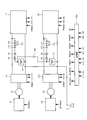
- FIG. 7 is a diagram illustrating a configuration example of a hybrid drive system according to the third embodiment.
- the hybrid system group in the first embodiment receives DC power from the DC overhead wire 1 as input, whereas the hybrid drive system in the third embodiment has AC power from the AC overhead wire 1b as input.
- the transformer 5 is provided on the input side of the power supply devices 11b and 21b, and the input voltage measuring unit that measures the voltage (transformer primary voltage: V3) applied to the primary side of the transformer 5. 6 is provided.
- V3 voltage measuring unit that measures the voltage
- FIG. 7 the same or equivalent components as those in the first embodiment are denoted by the same reference numerals, and redundant description is omitted.
- the effect of the inter-group contactor similar to that of the first embodiment, that is, the effective use of the power storage device when a failure occurs and the securing of the travel distance in the non-electrified section can be obtained.
- AC power from the AC overhead wire 1 b is input to the primary winding of the transformer 5 through the pantographs 2 a and 2 b and the overhead wire breaker 3.
- the transformer 5 has a number of secondary windings corresponding to the number of hybrid system groups, and steps down the overhead wire voltage to a voltage suitable for the main circuit of the power supply device (11b, 21b) at the subsequent stage.
- the output from the secondary winding of the transformer 5 is once input to the power supply device 11b via the contactors 14a and 14b and the charging resistor 14c.
- the contactor 14b has shown the form closed only at the time of charge operation. In this way, after the charging operation, the contactor 14b can be opened, and energization heat generation in the charging resistor 14c can be suppressed.
- the power supply devices 11b and 21b in the third embodiment are devices that convert the supplied AC power into DC power having a DC voltage suitable for the load devices 12 and 22 and the power storage devices 13 and 23.
- the control unit 200b Based on the measurement information of the input voltage measurement unit 6 that measures the primary side voltage of the transformer 5 and the input current information and output voltage information in each of the power supply devices 11b and 21b (not shown), the control unit 200b uses the power supply device. On / off signals (PWM signals) are generated for the semiconductor switches constituting the main circuit unit of the power supply device included in each of 11b and 21b. By this control, the AC / DC conversion operation is performed in the power supply apparatuses 11b and 21b.
- the load devices 12 and 22 may be propulsion control devices for propulsion control of the railway vehicle, auxiliary power supply devices for supplying power to devices other than the propulsion control device in the railway vehicle, It may be a power supply device.
- the load devices 12 and 22 convert the supplied DC power into AC power having variable frequency and variable voltage amplitude, AC motors driven by AC power, and The travel device is configured to transmit the driving force output from the AC motor to the wheels.
- the load devices 12 and 22 are auxiliary power supply devices, the load devices 12 and 22 convert the supplied DC power into AC power having a constant frequency and a constant voltage amplitude, and supply it to equipment mounted on the vehicle. I do.
- the effect of the inter-group contactor 100 similar to that of the first embodiment, that is, the effective use of the power storage device at the time of failure occurrence, the securing of the travel distance in the non-electrified section, the AC overhead line 1b It can be obtained under traveling conditions.
- FIG. 8 is a diagram illustrating a configuration example of a hybrid drive system according to the fourth embodiment.
- the power from the overhead line first and second embodiments: DC overhead line, third embodiment: AC overhead line
- the power generation device is an internal combustion engine. And a generator.
- FIG. 8 the same or equivalent components as those in the first embodiment are denoted by the same reference numerals, and redundant description is omitted.
- Engines 18 and 28 are internal combustion engines such as diesel engines, for example.
- the machine output shafts of the engines 18 and 28 and the rotating shafts of the generators 19 and 29 are directly connected or connected via gears, pulleys, etc. (not shown).
- the generators 19 and 29 are AC generators.
- three-phase AC power is obtained and input to the power supply devices 11c and 21c, respectively.
- the engines 18, 28, the generators 19, 29, and the power supply apparatuses 11c, 21c are components of the hybrid drive system, and are basically arranged and connected in the number of groups.
- the power supply devices 11c and 21c are power converters that convert AC power from the generators 19 and 29 into DC power for the power storage devices 13 and 23 and the load devices 12 and 22, and operate according to the following signal exchange.
- the controller 200c When the controller 200c wants to output DC power from the power supply devices 11c and 21c, it first outputs to the engines 18 and 28 notch signals (SP_ENG1 and SP_ENG2) that are digital bit signals corresponding to speed commands or speed commands. To do.
- the engines 18 and 28 start operation with speed characteristics in accordance with the command.
- the control unit 200c controls the torques of the generators 19 and 29 based on the input current information and the output voltage information obtained by the power supply devices 11c and 21c. By such control, power corresponding to speed ⁇ torque is generated in the generators 19 and 29, and a DC power output is obtained by the main circuit operation of the power supply apparatuses 11c and 21c.
- the configuration shown in the fourth embodiment is a device configuration that does not depend on the power from the overhead line, and the travel distance in the non-electrified section depends on the capacity of the power storage device as long as the remaining amount of fuel in the engine is taken into consideration. It is not a thing. However, if the load device in the failure group becomes unusable due to a failure in the power supply devices 11c and 21c, a failure in the engines 18 and 28, and the generators 19 and 29, the reduction in acceleration per composition is reduced as much as possible. In order to reduce the speed, the travel performance (torque characteristics) of the remaining load devices of the healthy group (emergency travel performance) may be included in the requirements of the railway vehicle.
- the amount of charge can be increased even if the output [W] cannot be increased if the operating time of the engine and generator on the healthy side is extended against the increase in capacity of the power storage device. The effect that it becomes easy to maintain running performance is acquired.
- the effect of the inter-group contactor similar to that of the first embodiment that is, the effect that the power of the power storage device when a failure occurs can be effectively used.
- Embodiment 5 the input to the power supply apparatus is power from an overhead line or generator output from the engine, but may be another power source such as a fuel cell. Needless to say. If the apparatus is configured using the inter-group contactor in the same manner as in the first to fourth embodiments, it is possible to configure a mode in which the power storage device is effectively used in the entire knitting when the power supply device or the load device fails.
- the configuration shown in the above embodiment is an example of the configuration of the present invention, and can be combined with another known technique, and a part thereof is omitted without departing from the gist of the present invention. Needless to say, it is possible to change the configuration.
- the present invention is useful as a hybrid drive system that can effectively use the power storage device provided on the power supply device side where the problem has occurred.
Landscapes
- Engineering & Computer Science (AREA)
- Power Engineering (AREA)
- Transportation (AREA)
- Mechanical Engineering (AREA)
- Sustainable Energy (AREA)
- Sustainable Development (AREA)
- Life Sciences & Earth Sciences (AREA)
- Chemical & Material Sciences (AREA)
- Combustion & Propulsion (AREA)
- Automation & Control Theory (AREA)
- Electric Propulsion And Braking For Vehicles (AREA)
- Charge And Discharge Circuits For Batteries Or The Like (AREA)
- Inverter Devices (AREA)
Abstract
Description
図1は、実施の形態1に係るハイブリッド駆動システムの一構成例を示す図である。図1において、実施の形態1に係るハイブリッド駆動システムは、直流架線1からの直流電力をパンタグラフ2(2a,2b)を介して受電し、受電した直流電力を架線遮断器3を介して電源装置11および電源装置21に供給(印加)する構成である。なお、電源装置11および電源装置21の負側は、それぞれ車輪4(4a,4b)を介してレールに接している。


図6は、実施の形態2に係るハイブリッド駆動システムの一構成例を示す図である。図1に示した実施の形態1におけるハイブリッドシステム群が、編成中に3つ以上存在する場合に、実施の形態1と同じ目的の群間接触器を設ける形態を示すものである。具体的には、ハイブリッドシステムの群の数をNとした場合に、同じ数の群間接触器、すなわちN個の群間接触器100-1~100-Nを設ける形態としている。なお、図6において、実施の形態1と同一または同等の構成部には同一の符号を付して、重複する説明は省略する。
(1)全ての制御部への運転指令(力行/回生/運転停止/リセット等)の出力
(2)全ての制御部の状態監視(電圧・電流状態監視、保護発生監視)
(3)何れかの群に保護が発生した際の何れかの群間接触器の接続処置
(1)統合制御部から入力された運転指令(力行/回生/運転停止/リセット等)に従った各群の電力変換制御
(2)各群の電圧・電流状態および保護発生状態を統合制御部300に出力
(3)統合制御部300から出力された群間接触器開閉指令に従った群間接触器操作
故障発生群の群間接触器を閉じると共に、健全群の群間接触器N-1個のうちの1つ以上を閉じるにあたり、前記N-1個のうちの1つ以上の接触器を選択するには下記表3に示すように自由度がある。なお、表中に示される数値は、1群のみ故障発生し、その蓄電装置を残り健全群の幾つかに接続した場合の充電容量を、群間接触器を接続しない健全群の蓄電装置充電容量を1とした場合の比で表したものである。

実施の形態1では、2台の負荷装置が共に故障すると、走行不可能となる他、2台の電源装置が故障すると、充電も不可能となり、蓄電装置容量が下限となると同様に走行不可能となる。一方、実施の形態2では、N個の負荷装置のうち少なくとも1つが健全で残っていれば、編成として走行は持続可能である。またその際に、蓄電装置を残存する負荷装置に接続すれば、非電化区間の走行距離は維持することが可能となる。さらに、N個の電源装置のうちの少なくとも1つが健全で残っていれば、群間接触器を接続することで、充電時間は延びるものの、編成の全ての蓄電装置に充電操作を行うことができ、非電化区間の走行距離を維持することができる。
図7は、実施の形態3に係るハイブリッド駆動システムの一構成例を示す図である。実施の形態1におけるハイブリッドシステム群が、直流架線1による直流電力を入力とすることに対し、実施の形態3におけるハイブリッド駆動システムは、交流架線1bの交流電力を入力とする形態である。具体的には、電源装置11b,21bの入力側に変圧器5が設けられると共に、変圧器5の1次側に印加される電圧(変圧器1次電圧:V3)を計測する入力電圧計測部6が設けられている。なお、図7において、実施の形態1と同一または同等の構成部には同一の符号を付して、重複する説明は省略する。
図8は、実施の形態4に係るハイブリッド駆動システムの一構成例を示す図である。実施の形態1~3が架線(実施の形態1,2:直流架線、実施の形態3:交流架線)からの電力を入力とすることに対し、実施の形態4では、電力発生装置を内燃機関および発電機とする構成である。なお、図8において、実施の形態1と同一または同等の構成部には同一の符号を付して、重複する説明は省略する。
図示はしないが、実施の形態1~4において、電源装置への入力は、架線からの電力もしくは、エンジンからの発電機出力であったが、燃料電池等の他の電力源であってもよいことは言うまでもない。実施の形態1~4と同様に群間接触器を用いて装置を構成すれば、電源装置もしくは負荷装置の故障時に、蓄電装置を編成全体で有効利用する形態は構成可能である。
Claims (15)
- 直流電力を供給する第1、第2の電源装置と、前記第1、第2の電源装置それぞれに接続され、直流電力を蓄積または放出する第1、第2の蓄電装置と、前記第1の電源装置および前記第1の蓄電装置から直流電力の供給を受けて第1の負荷を駆動する第1の負荷装置と、前記第2の電源装置および前記第2の蓄電装置から直流電力の供給を受けて第2の負荷を駆動する第2の負荷装置と、を備えたハイブリッド駆動システムであって、
前記第1の蓄電装置と前記第2の蓄電装置の各入力端子間を電気的に開閉するための群間接触器を備えたことを特徴とするハイブリッド駆動システム。 - 前記群間接触器は、通常時は開放状態とされ、
前記第1、第2の電源装置、前記第1、第2の負荷装置のうちの何れかが不具合によって停止した場合に閉じられることを特徴とする請求項1に記載のハイブリッド駆動システム。 - 直流電力を供給する電源装置と、前記電源装置に接続され直流電力を蓄積または放出する蓄電装置と、前記電源装置と前記蓄電装置から直流電力の供給を受けて負荷を駆動する負荷装置と、前記蓄電装置の入出力端子を他の蓄電装置の入出力端子と電気的に接続するための群間接触器と、を備えたシステム群を2群以上備えることを特徴とするハイブリッド駆動システム。
- 通常時は全ての群間接触器を開放状態としておき、
複数群のうちの一つのシステム群における電源装置あるいは負荷装置が不具合によって運転停止した場合には、当該不具合のあったシステム群における群間接触器を閉じると共に、他のシステム群における群間接触器のうちの少なくとも一つを閉じることで、運転停止した電源装置を含むシステム群内の蓄電装置を他のシステム群に接続することを特徴とする請求項3に記載のハイブリッド駆動システム。 - 全ての電源装置の入力あるいは出力には回路開放用の開閉機器類を備え、
電源装置の何れかが不具合によって停止した場合に、停止させた電源装置の入力あるいは出力の開閉機器を開放することを特徴とする請求項1乃至4のいずれか一項に記載のハイブリッド駆動システム。 - 前記群間接触器を閉じる際には、前記蓄電装置間の出力電圧の差異値が設定した閾値より小さい状態となった後に閉じることを特徴とする請求項1乃至4のいずれか一項に記載のハイブリッド駆動システム。
- 不具合の発生していない側のシステム群における蓄電装置の充放電により蓄電装置間の電圧差を縮めておくことを特徴とする請求項6に記載のハイブリッド駆動システム。
- 不具合の発生したシステム群の蓄電装置電圧が、不具合の発生していないシステム群の蓄電装置電圧より大きい場合には、当該不具合の発生していないシステム群にある負荷装置の力行性能を抑制するか、もしくは力行を禁止することで蓄電装置間の電圧差を縮めることを特徴とする請求項6に記載のハイブリッド駆動システム。
- 不具合の発生したシステム群の蓄電装置電圧が、不具合の発生していないシステム群の蓄電装置電圧より小さい場合には、当該不具合の発生していないシステム群にある負荷装置の回生を抑制することで蓄電装置間の電圧差を縮めることを特徴とする請求項6に記載のハイブリッド駆動システム。
- 前記負荷装置は、供給された直流電力を可変周波数可変電圧振幅の交流電力に変換する電力変換装置と、前記交流電力により駆動される交流電動機と、を備えたことを特徴とする請求項1乃至4のいずれか一項に記載のハイブリッド駆動システム。
- 前記負荷装置は、供給された直流電力を一定周波数一定電圧振幅の交流電力に変換し、車両に搭載された機器に供給することを特徴とする請求項1乃至4のいずれか一項に記載のハイブリッド駆動システム。
- 前記電源装置は、直流架線から供給された直流電力の電圧値を、前記蓄電装置に適した直流電圧に変換する直流-直流変換器であることを特徴とする請求項1乃至4のいずれか一項に記載のハイブリッド駆動システム。
- 前記電源装置は、交流架線から供給された交流電力を、前記蓄電装置に適した直流電圧の直流電力に変換する交流-直流変換器であることを特徴とする請求項1乃至4のいずれか一項に記載のハイブリッド駆動システム。
- 前記電源装置は、内燃機関により駆動される発電機と、前記発電機から供給された交流電力を、前記蓄電装置に適した直流電圧の直流電力に変換する交流-直流変換器であることを特徴とする請求項1乃至4のいずれか一項に記載のハイブリッド駆動システム。
- 前記電源装置は、燃料電池と、この燃料電池から供給された直流電力を、前記蓄電装置に適した直流電圧の直流電力に変換する直流-直流変換器であることを特徴とする請求項1乃至4のいずれか一項に記載のハイブリッド駆動システム。
Priority Applications (7)
| Application Number | Priority Date | Filing Date | Title |
|---|---|---|---|
| PCT/JP2013/068176 WO2015001621A1 (ja) | 2013-07-02 | 2013-07-02 | ハイブリッド駆動システム |
| CA2917083A CA2917083C (en) | 2013-07-02 | 2013-07-02 | Hybrid drive system |
| JP2015524941A JP5944050B2 (ja) | 2013-07-02 | 2013-07-02 | ハイブリッド駆動システム |
| EP13888726.0A EP3000646B2 (en) | 2013-07-02 | 2013-07-02 | Hybrid drive system |
| US14/890,872 US10065511B2 (en) | 2013-07-02 | 2013-07-02 | Hybrid drive system |
| AU2013393444A AU2013393444B2 (en) | 2013-07-02 | 2013-07-02 | Hybrid drive system |
| CN201390001223.9U CN205326821U (zh) | 2013-07-02 | 2013-07-02 | 组合驱动系统 |
Applications Claiming Priority (1)
| Application Number | Priority Date | Filing Date | Title |
|---|---|---|---|
| PCT/JP2013/068176 WO2015001621A1 (ja) | 2013-07-02 | 2013-07-02 | ハイブリッド駆動システム |
Publications (1)
| Publication Number | Publication Date |
|---|---|
| WO2015001621A1 true WO2015001621A1 (ja) | 2015-01-08 |
Family
ID=52143243
Family Applications (1)
| Application Number | Title | Priority Date | Filing Date |
|---|---|---|---|
| PCT/JP2013/068176 Ceased WO2015001621A1 (ja) | 2013-07-02 | 2013-07-02 | ハイブリッド駆動システム |
Country Status (7)
| Country | Link |
|---|---|
| US (1) | US10065511B2 (ja) |
| EP (1) | EP3000646B2 (ja) |
| JP (1) | JP5944050B2 (ja) |
| CN (1) | CN205326821U (ja) |
| AU (1) | AU2013393444B2 (ja) |
| CA (1) | CA2917083C (ja) |
| WO (1) | WO2015001621A1 (ja) |
Cited By (9)
| Publication number | Priority date | Publication date | Assignee | Title |
|---|---|---|---|---|
| JP2017073916A (ja) * | 2015-10-08 | 2017-04-13 | 本田技研工業株式会社 | 駆動装置、輸送機器及び制御方法 |
| WO2018229863A1 (ja) * | 2017-06-13 | 2018-12-20 | 株式会社東芝 | 鉄道車両 |
| WO2019039263A1 (ja) * | 2017-08-24 | 2019-02-28 | 株式会社オートネットワーク技術研究所 | 電源システム及び電気自動車 |
| WO2019208383A1 (ja) * | 2018-04-23 | 2019-10-31 | 株式会社東芝 | 電気車用電源システム |
| KR20200055172A (ko) * | 2018-11-12 | 2020-05-21 | 한국철도기술연구원 | 가선전압 제어장치 및 방법 |
| WO2020152733A1 (ja) * | 2019-01-21 | 2020-07-30 | 三菱電機株式会社 | 電力変換装置 |
| CN111734544A (zh) * | 2020-07-01 | 2020-10-02 | 联合汽车电子(重庆)有限公司 | 汽车怠速运行工况下智能电机的前置控制方法 |
| EP3265358B1 (de) | 2015-03-05 | 2020-12-30 | Stadler Rail AG | Schienenfahrzeug, verfahren zum antreiben eines schienenfahrzeugs sowie verfahren zur herstellung eines schienenfahrzeugs |
| JP7331294B1 (ja) * | 2022-11-30 | 2023-08-22 | 三菱電機株式会社 | 電源切替装置および駆動制御装置 |
Families Citing this family (17)
| Publication number | Priority date | Publication date | Assignee | Title |
|---|---|---|---|---|
| DE102013202236B4 (de) * | 2013-02-12 | 2019-01-10 | Siemens Aktiengesellschaft | Schienenfahrzeug |
| DE102014006028B4 (de) * | 2014-04-24 | 2022-06-30 | Audi Ag | Multibatteriesystem zur Erhöhung der elektrischen Reichweite |
| KR101546822B1 (ko) * | 2015-07-06 | 2015-08-24 | (주)누리일렉콤 | 풍력 발전기 |
| GB201514204D0 (en) * | 2015-08-11 | 2015-09-23 | Vivarail Ltd | Electric rail carriage |
| KR101887749B1 (ko) * | 2016-07-15 | 2018-08-10 | 현대오트론 주식회사 | 하이브리드 및 전기 자동차의 전력 분산 제어 시스템 및 방법 |
| DE102018105318B3 (de) * | 2018-03-08 | 2019-03-21 | SCHOTT Diamantwerkzeuge GmbH | Akkubetriebene Ultraschall- Handbohrmaschine sowie Verfahren zum Betreiben einer solchen Ultraschall- Handbohrmaschine |
| GB2574264B (en) | 2018-06-01 | 2021-05-19 | Vivarail Ltd | Rail transport vehicle electric energy storage and charging system |
| DE102018212405B4 (de) | 2018-07-25 | 2025-11-20 | Volkswagen Aktiengesellschaft | Traktionsnetz und Verfahren zum Betreiben eines Traktionsnetzes eines elektrisch angetriebenen Fahrzeugs im Kurzschlussfall |
| CN111775974B (zh) * | 2020-06-21 | 2023-02-28 | 中车永济电机有限公司 | 动车组用动力包及其控制方法 |
| FR3112728B1 (fr) * | 2020-07-27 | 2022-09-09 | Alstom Transp Tech | Ensemble de traction constitué d’une locomotive et d’un tender ; procédé associé. |
| EP3955407A1 (en) | 2020-08-12 | 2022-02-16 | CAF Power & Automation, S.L.U. | Redundant power system |
| CN112158083B (zh) * | 2020-09-24 | 2022-06-14 | 中车株洲电力机车有限公司 | 一种紧急制动下机车牵引切除控制系统及方法 |
| DE102021203026A1 (de) * | 2021-03-26 | 2022-09-29 | Siemens Mobility GmbH | Fahrzeugtraktionssystem |
| CN113799663B (zh) * | 2021-11-19 | 2022-03-04 | 西南交通大学 | 一种动车供电传动系统、交直交牵引变流器及其控制方法 |
| CN115503510A (zh) * | 2022-10-19 | 2022-12-23 | 中车株洲电力机车有限公司 | 电力机车及其供电装置、方法 |
| US12304329B2 (en) * | 2022-11-07 | 2025-05-20 | Caterpillar Inc. | Electrical architecture for battery powered machine |
| GB2629580B (en) * | 2023-05-02 | 2026-03-18 | Hitachi Rail Ltd | Combined switching system for an electrically powered railway vehicle |
Citations (6)
| Publication number | Priority date | Publication date | Assignee | Title |
|---|---|---|---|---|
| JPS5094460A (ja) * | 1973-12-24 | 1975-07-28 | ||
| JP2004336833A (ja) * | 2003-04-30 | 2004-11-25 | Hitachi Ltd | 鉄道車両用電力変換器の制御装置 |
| JP2005083218A (ja) * | 2003-09-05 | 2005-03-31 | Hokkaido Railway Co | 気動車および編成車両 |
| JP2008042989A (ja) * | 2006-08-02 | 2008-02-21 | Hitachi Ltd | 鉄道車両システム |
| JP2008187884A (ja) * | 2007-01-04 | 2008-08-14 | Toyota Motor Corp | 電源システムおよびそれを備える車両、ならびにその制御方法 |
| JP2011041386A (ja) * | 2009-08-10 | 2011-02-24 | Toyota Motor Corp | 車両および車両の制御方法 |
Family Cites Families (14)
| Publication number | Priority date | Publication date | Assignee | Title |
|---|---|---|---|---|
| DE10045319A1 (de) | 2000-09-12 | 2002-03-21 | Alstom Lhb Gmbh | Schienentriebfahrzeug mit Energieversorgungssystem |
| JP4230189B2 (ja) * | 2002-10-03 | 2009-02-25 | 株式会社日立製作所 | ディスクアレイ装置、及びその電源供給方法 |
| US20100144219A1 (en) * | 2008-12-05 | 2010-06-10 | Brunswick Corporation | Marine Vessel Hybrid Propulsion System |
| WO2010089843A1 (ja) * | 2009-02-03 | 2010-08-12 | トヨタ自動車株式会社 | 車両の充電システムおよび充電システムの制御方法 |
| DE102009008549A1 (de) | 2009-02-12 | 2010-08-19 | Bombardier Transportation Gmbh | Anordnung zum Betreiben von Verbrauchern in einem Schienenfahrzeug mit elektrischer Energie, wahlweise aus einem Energieversorgungsnetz oder aus einer Motor-Generator-Kombination |
| US7928598B2 (en) * | 2009-04-03 | 2011-04-19 | General Electric Company | Apparatus, method, and system for conveying electrical energy |
| ES2384819T3 (es) * | 2009-04-22 | 2012-07-12 | Claus-D. Christophel | Sistema de accionamiento para un barco |
| CN102803007B (zh) | 2009-06-15 | 2015-09-16 | 株式会社日立制作所 | 铁路车辆的驱动系统 |
| JP5398634B2 (ja) | 2010-05-12 | 2014-01-29 | 株式会社東芝 | 交流電気車 |
| US9145060B2 (en) * | 2011-07-29 | 2015-09-29 | Mitsubishi Electric Corporation | Propulsion control apparatus for electric motor car |
| DE102011109709B4 (de) † | 2011-08-06 | 2022-12-01 | Volkswagen Aktiengesellschaft | Verfahren und System zur Spannungsversorgung eines Bordnetzes eines Fahrzeugs |
| WO2013021486A1 (ja) | 2011-08-10 | 2013-02-14 | 三菱電機株式会社 | 車両用制御装置およびディーゼルハイブリッド車両システム |
| US20140244107A1 (en) * | 2013-02-28 | 2014-08-28 | C.E. Niehoff & Co. | Battery charge voltage compensating system and method of operation |
| CN106143171A (zh) * | 2015-03-31 | 2016-11-23 | 通用电气公司 | 多源能量存储系统及能量管理控制方法 |
-
2013
- 2013-07-02 US US14/890,872 patent/US10065511B2/en active Active
- 2013-07-02 WO PCT/JP2013/068176 patent/WO2015001621A1/ja not_active Ceased
- 2013-07-02 EP EP13888726.0A patent/EP3000646B2/en active Active
- 2013-07-02 CA CA2917083A patent/CA2917083C/en not_active Expired - Fee Related
- 2013-07-02 CN CN201390001223.9U patent/CN205326821U/zh not_active Expired - Lifetime
- 2013-07-02 JP JP2015524941A patent/JP5944050B2/ja active Active
- 2013-07-02 AU AU2013393444A patent/AU2013393444B2/en not_active Ceased
Patent Citations (7)
| Publication number | Priority date | Publication date | Assignee | Title |
|---|---|---|---|---|
| JPS5094460A (ja) * | 1973-12-24 | 1975-07-28 | ||
| JP2004336833A (ja) * | 2003-04-30 | 2004-11-25 | Hitachi Ltd | 鉄道車両用電力変換器の制御装置 |
| JP4166618B2 (ja) | 2003-04-30 | 2008-10-15 | 株式会社日立製作所 | 鉄道車両用誘導電動機の駆動システム |
| JP2005083218A (ja) * | 2003-09-05 | 2005-03-31 | Hokkaido Railway Co | 気動車および編成車両 |
| JP2008042989A (ja) * | 2006-08-02 | 2008-02-21 | Hitachi Ltd | 鉄道車両システム |
| JP2008187884A (ja) * | 2007-01-04 | 2008-08-14 | Toyota Motor Corp | 電源システムおよびそれを備える車両、ならびにその制御方法 |
| JP2011041386A (ja) * | 2009-08-10 | 2011-02-24 | Toyota Motor Corp | 車両および車両の制御方法 |
Non-Patent Citations (1)
| Title |
|---|
| See also references of EP3000646A4 |
Cited By (17)
| Publication number | Priority date | Publication date | Assignee | Title |
|---|---|---|---|---|
| EP3265358B1 (de) | 2015-03-05 | 2020-12-30 | Stadler Rail AG | Schienenfahrzeug, verfahren zum antreiben eines schienenfahrzeugs sowie verfahren zur herstellung eines schienenfahrzeugs |
| JP2017073916A (ja) * | 2015-10-08 | 2017-04-13 | 本田技研工業株式会社 | 駆動装置、輸送機器及び制御方法 |
| WO2018229863A1 (ja) * | 2017-06-13 | 2018-12-20 | 株式会社東芝 | 鉄道車両 |
| JPWO2018229863A1 (ja) * | 2017-06-13 | 2020-05-21 | 株式会社東芝 | 鉄道車両 |
| WO2019039263A1 (ja) * | 2017-08-24 | 2019-02-28 | 株式会社オートネットワーク技術研究所 | 電源システム及び電気自動車 |
| JP2019041468A (ja) * | 2017-08-24 | 2019-03-14 | 株式会社オートネットワーク技術研究所 | 電源システム及び電気自動車 |
| WO2019208383A1 (ja) * | 2018-04-23 | 2019-10-31 | 株式会社東芝 | 電気車用電源システム |
| JP2019193405A (ja) * | 2018-04-23 | 2019-10-31 | 株式会社東芝 | 電気車用電源システム |
| JP7182898B2 (ja) | 2018-04-23 | 2022-12-05 | 株式会社東芝 | 電気車用電源システム |
| KR20200055172A (ko) * | 2018-11-12 | 2020-05-21 | 한국철도기술연구원 | 가선전압 제어장치 및 방법 |
| KR102155833B1 (ko) | 2018-11-12 | 2020-09-15 | 한국철도기술연구원 | 가선전압 제어장치 및 방법 |
| WO2020152733A1 (ja) * | 2019-01-21 | 2020-07-30 | 三菱電機株式会社 | 電力変換装置 |
| JPWO2020152733A1 (ja) * | 2019-01-21 | 2021-11-11 | 三菱電機株式会社 | 電力変換装置 |
| CN111734544B (zh) * | 2020-07-01 | 2022-06-10 | 联合汽车电子(重庆)有限公司 | 汽车怠速运行工况下智能电机的前置控制方法 |
| CN111734544A (zh) * | 2020-07-01 | 2020-10-02 | 联合汽车电子(重庆)有限公司 | 汽车怠速运行工况下智能电机的前置控制方法 |
| JP7331294B1 (ja) * | 2022-11-30 | 2023-08-22 | 三菱電機株式会社 | 電源切替装置および駆動制御装置 |
| WO2024116317A1 (ja) * | 2022-11-30 | 2024-06-06 | 三菱電機株式会社 | 電源切替装置および駆動制御装置 |
Also Published As
| Publication number | Publication date |
|---|---|
| CA2917083C (en) | 2018-02-27 |
| US10065511B2 (en) | 2018-09-04 |
| EP3000646B2 (en) | 2023-03-22 |
| EP3000646A4 (en) | 2017-05-03 |
| AU2013393444A1 (en) | 2015-11-12 |
| US20160082850A1 (en) | 2016-03-24 |
| EP3000646B1 (en) | 2020-05-13 |
| JP5944050B2 (ja) | 2016-07-05 |
| EP3000646A1 (en) | 2016-03-30 |
| CA2917083A1 (en) | 2015-01-08 |
| JPWO2015001621A1 (ja) | 2017-02-23 |
| CN205326821U (zh) | 2016-06-22 |
| AU2013393444B2 (en) | 2017-01-05 |
Similar Documents
| Publication | Publication Date | Title |
|---|---|---|
| JP5944050B2 (ja) | ハイブリッド駆動システム | |
| JP6072912B2 (ja) | ハイブリッド駆動システム | |
| US9868355B2 (en) | Propulsion control apparatus for railroad vehicle | |
| JP5611345B2 (ja) | 車載システム用の回路装置 | |
| JP5182310B2 (ja) | 鉄道編成車両の駆動システム | |
| WO2011021443A1 (ja) | 電気車推進用電力変換装置 | |
| EP3955407A1 (en) | Redundant power system | |
| JP7516673B2 (ja) | 鉄道車両用の駆動システムおよび駆動方法 | |
| WO2017104204A1 (ja) | 車両 | |
| JP2010233384A (ja) | 電源装置 | |
| US8552681B2 (en) | Power storage system for a rail-guided vehicle | |
| JP5352731B2 (ja) | 鉄道編成車両の駆動システム | |
| EP3858652B1 (en) | Sistema de alimentación para un tren eléctrico, y tren eléctrico | |
| JP6259778B2 (ja) | 鉄道車両用駆動装置 | |
| JP7614784B2 (ja) | 車両駆動装置 | |
| KR102338125B1 (ko) | 육상 ac 전력과 연계 가능한 선박용 dc 기반 전력 공급 시스템 | |
| JP2024163788A (ja) | 駆動システム |
Legal Events
| Date | Code | Title | Description |
|---|---|---|---|
| 121 | Ep: the epo has been informed by wipo that ep was designated in this application |
Ref document number: 13888726 Country of ref document: EP Kind code of ref document: A1 |
|
| ENP | Entry into the national phase |
Ref document number: 2015524941 Country of ref document: JP Kind code of ref document: A |
|
| ENP | Entry into the national phase |
Ref document number: 2013393444 Country of ref document: AU Date of ref document: 20130702 Kind code of ref document: A |
|
| WWE | Wipo information: entry into national phase |
Ref document number: 14890872 Country of ref document: US |
|
| WWE | Wipo information: entry into national phase |
Ref document number: 2013888726 Country of ref document: EP |
|
| ENP | Entry into the national phase |
Ref document number: 2917083 Country of ref document: CA |
|
| NENP | Non-entry into the national phase |
Ref country code: DE |