WO2015001699A1 - 蓄電装置、蓄電システム、電子機器、電動車両および電力システム - Google Patents
蓄電装置、蓄電システム、電子機器、電動車両および電力システム Download PDFInfo
- Publication number
- WO2015001699A1 WO2015001699A1 PCT/JP2014/002624 JP2014002624W WO2015001699A1 WO 2015001699 A1 WO2015001699 A1 WO 2015001699A1 JP 2014002624 W JP2014002624 W JP 2014002624W WO 2015001699 A1 WO2015001699 A1 WO 2015001699A1
- Authority
- WO
- WIPO (PCT)
- Prior art keywords
- battery
- power storage
- storage device
- case
- power
- Prior art date
- Legal status (The legal status is an assumption and is not a legal conclusion. Google has not performed a legal analysis and makes no representation as to the accuracy of the status listed.)
- Ceased
Links
Images









Classifications
-
- H—ELECTRICITY
- H01—ELECTRIC ELEMENTS
- H01M—PROCESSES OR MEANS, e.g. BATTERIES, FOR THE DIRECT CONVERSION OF CHEMICAL ENERGY INTO ELECTRICAL ENERGY
- H01M10/00—Secondary cells; Manufacture thereof
- H01M10/42—Methods or arrangements for servicing or maintenance of secondary cells or secondary half-cells
- H01M10/48—Accumulators combined with arrangements for measuring, testing or indicating the condition of cells, e.g. the level or density of the electrolyte
- H01M10/482—Accumulators combined with arrangements for measuring, testing or indicating the condition of cells, e.g. the level or density of the electrolyte for several batteries or cells simultaneously or sequentially
-
- B—PERFORMING OPERATIONS; TRANSPORTING
- B60—VEHICLES IN GENERAL
- B60R—VEHICLES, VEHICLE FITTINGS, OR VEHICLE PARTS, NOT OTHERWISE PROVIDED FOR
- B60R16/00—Electric or fluid circuits specially adapted for vehicles and not otherwise provided for; Arrangement of elements of electric or fluid circuits specially adapted for vehicles and not otherwise provided for
- B60R16/02—Electric or fluid circuits specially adapted for vehicles and not otherwise provided for; Arrangement of elements of electric or fluid circuits specially adapted for vehicles and not otherwise provided for electric constitutive elements
- B60R16/03—Electric or fluid circuits specially adapted for vehicles and not otherwise provided for; Arrangement of elements of electric or fluid circuits specially adapted for vehicles and not otherwise provided for electric constitutive elements for supply of electrical power to vehicle subsystems or for
- B60R16/033—Electric or fluid circuits specially adapted for vehicles and not otherwise provided for; Arrangement of elements of electric or fluid circuits specially adapted for vehicles and not otherwise provided for electric constitutive elements for supply of electrical power to vehicle subsystems or for characterised by the use of electrical cells or batteries
-
- H—ELECTRICITY
- H01—ELECTRIC ELEMENTS
- H01G—CAPACITORS; CAPACITORS, RECTIFIERS, DETECTORS, SWITCHING DEVICES, LIGHT-SENSITIVE OR TEMPERATURE-SENSITIVE DEVICES OF THE ELECTROLYTIC TYPE
- H01G11/00—Hybrid capacitors, i.e. capacitors having different positive and negative electrodes; Electric double-layer [EDL] capacitors; Processes for the manufacture thereof or of parts thereof
- H01G11/10—Multiple hybrid or EDL capacitors, e.g. arrays or modules
-
- H—ELECTRICITY
- H01—ELECTRIC ELEMENTS
- H01G—CAPACITORS; CAPACITORS, RECTIFIERS, DETECTORS, SWITCHING DEVICES, LIGHT-SENSITIVE OR TEMPERATURE-SENSITIVE DEVICES OF THE ELECTROLYTIC TYPE
- H01G11/00—Hybrid capacitors, i.e. capacitors having different positive and negative electrodes; Electric double-layer [EDL] capacitors; Processes for the manufacture thereof or of parts thereof
- H01G11/74—Terminals, e.g. extensions of current collectors
- H01G11/76—Terminals, e.g. extensions of current collectors specially adapted for integration in multiple or stacked hybrid or EDL capacitors
-
- H—ELECTRICITY
- H01—ELECTRIC ELEMENTS
- H01G—CAPACITORS; CAPACITORS, RECTIFIERS, DETECTORS, SWITCHING DEVICES, LIGHT-SENSITIVE OR TEMPERATURE-SENSITIVE DEVICES OF THE ELECTROLYTIC TYPE
- H01G11/00—Hybrid capacitors, i.e. capacitors having different positive and negative electrodes; Electric double-layer [EDL] capacitors; Processes for the manufacture thereof or of parts thereof
- H01G11/78—Cases; Housings; Encapsulations; Mountings
- H01G11/82—Fixing or assembling a capacitive element in a housing, e.g. mounting electrodes, current collectors or terminals in containers or encapsulations
-
- H—ELECTRICITY
- H01—ELECTRIC ELEMENTS
- H01M—PROCESSES OR MEANS, e.g. BATTERIES, FOR THE DIRECT CONVERSION OF CHEMICAL ENERGY INTO ELECTRICAL ENERGY
- H01M10/00—Secondary cells; Manufacture thereof
- H01M10/42—Methods or arrangements for servicing or maintenance of secondary cells or secondary half-cells
- H01M10/425—Structural combination with electronic components, e.g. electronic circuits integrated to the outside of the casing
-
- H—ELECTRICITY
- H01—ELECTRIC ELEMENTS
- H01M—PROCESSES OR MEANS, e.g. BATTERIES, FOR THE DIRECT CONVERSION OF CHEMICAL ENERGY INTO ELECTRICAL ENERGY
- H01M50/00—Constructional details or processes of manufacture of the non-active parts of electrochemical cells other than fuel cells, e.g. hybrid cells
- H01M50/20—Mountings; Secondary casings or frames; Racks, modules or packs; Suspension devices; Shock absorbers; Transport or carrying devices; Holders
- H01M50/204—Racks, modules or packs for multiple batteries or multiple cells
- H01M50/207—Racks, modules or packs for multiple batteries or multiple cells characterised by their shape
- H01M50/213—Racks, modules or packs for multiple batteries or multiple cells characterised by their shape adapted for cells having curved cross-section, e.g. round or elliptic
-
- H—ELECTRICITY
- H01—ELECTRIC ELEMENTS
- H01M—PROCESSES OR MEANS, e.g. BATTERIES, FOR THE DIRECT CONVERSION OF CHEMICAL ENERGY INTO ELECTRICAL ENERGY
- H01M50/00—Constructional details or processes of manufacture of the non-active parts of electrochemical cells other than fuel cells, e.g. hybrid cells
- H01M50/20—Mountings; Secondary casings or frames; Racks, modules or packs; Suspension devices; Shock absorbers; Transport or carrying devices; Holders
- H01M50/218—Mountings; Secondary casings or frames; Racks, modules or packs; Suspension devices; Shock absorbers; Transport or carrying devices; Holders characterised by the material
- H01M50/22—Mountings; Secondary casings or frames; Racks, modules or packs; Suspension devices; Shock absorbers; Transport or carrying devices; Holders characterised by the material of the casings or racks
- H01M50/222—Inorganic material
- H01M50/224—Metals
-
- H—ELECTRICITY
- H01—ELECTRIC ELEMENTS
- H01M—PROCESSES OR MEANS, e.g. BATTERIES, FOR THE DIRECT CONVERSION OF CHEMICAL ENERGY INTO ELECTRICAL ENERGY
- H01M50/00—Constructional details or processes of manufacture of the non-active parts of electrochemical cells other than fuel cells, e.g. hybrid cells
- H01M50/20—Mountings; Secondary casings or frames; Racks, modules or packs; Suspension devices; Shock absorbers; Transport or carrying devices; Holders
- H01M50/284—Mountings; Secondary casings or frames; Racks, modules or packs; Suspension devices; Shock absorbers; Transport or carrying devices; Holders with incorporated circuit boards, e.g. printed circuit boards [PCB]
-
- H—ELECTRICITY
- H01—ELECTRIC ELEMENTS
- H01M—PROCESSES OR MEANS, e.g. BATTERIES, FOR THE DIRECT CONVERSION OF CHEMICAL ENERGY INTO ELECTRICAL ENERGY
- H01M50/00—Constructional details or processes of manufacture of the non-active parts of electrochemical cells other than fuel cells, e.g. hybrid cells
- H01M50/20—Mountings; Secondary casings or frames; Racks, modules or packs; Suspension devices; Shock absorbers; Transport or carrying devices; Holders
- H01M50/296—Mountings; Secondary casings or frames; Racks, modules or packs; Suspension devices; Shock absorbers; Transport or carrying devices; Holders characterised by terminals of battery packs
-
- H—ELECTRICITY
- H01—ELECTRIC ELEMENTS
- H01M—PROCESSES OR MEANS, e.g. BATTERIES, FOR THE DIRECT CONVERSION OF CHEMICAL ENERGY INTO ELECTRICAL ENERGY
- H01M50/00—Constructional details or processes of manufacture of the non-active parts of electrochemical cells other than fuel cells, e.g. hybrid cells
- H01M50/50—Current conducting connections for cells or batteries
- H01M50/502—Interconnectors for connecting terminals of adjacent batteries; Interconnectors for connecting cells outside a battery casing
- H01M50/519—Interconnectors for connecting terminals of adjacent batteries; Interconnectors for connecting cells outside a battery casing comprising printed circuit boards [PCB]
-
- H—ELECTRICITY
- H02—GENERATION; CONVERSION OR DISTRIBUTION OF ELECTRIC POWER
- H02J—ELECTRIC POWER NETWORKS; CIRCUIT ARRANGEMENTS OR SYSTEMS FOR SUPPLYING OR DISTRIBUTING ELECTRIC POWER; SYSTEMS FOR STORING ELECTRIC ENERGY
- H02J7/00—Circuit arrangements for charging or discharging batteries or for supplying loads from batteries
- H02J7/34—Parallel operation in networks using both storage and other DC sources, e.g. providing buffering
-
- H—ELECTRICITY
- H02—GENERATION; CONVERSION OR DISTRIBUTION OF ELECTRIC POWER
- H02J—ELECTRIC POWER NETWORKS; CIRCUIT ARRANGEMENTS OR SYSTEMS FOR SUPPLYING OR DISTRIBUTING ELECTRIC POWER; SYSTEMS FOR STORING ELECTRIC ENERGY
- H02J7/00—Circuit arrangements for charging or discharging batteries or for supplying loads from batteries
- H02J7/34—Parallel operation in networks using both storage and other DC sources, e.g. providing buffering
- H02J7/35—Parallel operation in networks using both storage and other DC sources, e.g. providing buffering with light sensitive cells
-
- H—ELECTRICITY
- H02—GENERATION; CONVERSION OR DISTRIBUTION OF ELECTRIC POWER
- H02J—ELECTRIC POWER NETWORKS; CIRCUIT ARRANGEMENTS OR SYSTEMS FOR SUPPLYING OR DISTRIBUTING ELECTRIC POWER; SYSTEMS FOR STORING ELECTRIC ENERGY
- H02J7/00—Circuit arrangements for charging or discharging batteries or for supplying loads from batteries
- H02J7/50—Circuit arrangements for charging or discharging batteries or for supplying loads from batteries acting upon multiple batteries simultaneously or sequentially
-
- H—ELECTRICITY
- H02—GENERATION; CONVERSION OR DISTRIBUTION OF ELECTRIC POWER
- H02J—ELECTRIC POWER NETWORKS; CIRCUIT ARRANGEMENTS OR SYSTEMS FOR SUPPLYING OR DISTRIBUTING ELECTRIC POWER; SYSTEMS FOR STORING ELECTRIC ENERGY
- H02J7/00—Circuit arrangements for charging or discharging batteries or for supplying loads from batteries
- H02J7/70—Circuit arrangements for charging or discharging batteries or for supplying loads from batteries characterised by the mechanical construction
-
- H—ELECTRICITY
- H01—ELECTRIC ELEMENTS
- H01M—PROCESSES OR MEANS, e.g. BATTERIES, FOR THE DIRECT CONVERSION OF CHEMICAL ENERGY INTO ELECTRICAL ENERGY
- H01M10/00—Secondary cells; Manufacture thereof
- H01M10/05—Accumulators with non-aqueous electrolyte
- H01M10/052—Li-accumulators
- H01M10/0525—Rocking-chair batteries, i.e. batteries with lithium insertion or intercalation in both electrodes; Lithium-ion batteries
-
- H—ELECTRICITY
- H01—ELECTRIC ELEMENTS
- H01M—PROCESSES OR MEANS, e.g. BATTERIES, FOR THE DIRECT CONVERSION OF CHEMICAL ENERGY INTO ELECTRICAL ENERGY
- H01M10/00—Secondary cells; Manufacture thereof
- H01M10/42—Methods or arrangements for servicing or maintenance of secondary cells or secondary half-cells
- H01M10/48—Accumulators combined with arrangements for measuring, testing or indicating the condition of cells, e.g. the level or density of the electrolyte
- H01M10/486—Accumulators combined with arrangements for measuring, testing or indicating the condition of cells, e.g. the level or density of the electrolyte for measuring temperature
-
- H—ELECTRICITY
- H01—ELECTRIC ELEMENTS
- H01M—PROCESSES OR MEANS, e.g. BATTERIES, FOR THE DIRECT CONVERSION OF CHEMICAL ENERGY INTO ELECTRICAL ENERGY
- H01M10/00—Secondary cells; Manufacture thereof
- H01M10/42—Methods or arrangements for servicing or maintenance of secondary cells or secondary half-cells
- H01M10/425—Structural combination with electronic components, e.g. electronic circuits integrated to the outside of the casing
- H01M2010/4278—Systems for data transfer from batteries, e.g. transfer of battery parameters to a controller, data transferred between battery controller and main controller
-
- H—ELECTRICITY
- H01—ELECTRIC ELEMENTS
- H01M—PROCESSES OR MEANS, e.g. BATTERIES, FOR THE DIRECT CONVERSION OF CHEMICAL ENERGY INTO ELECTRICAL ENERGY
- H01M2220/00—Batteries for particular applications
- H01M2220/10—Batteries in stationary systems, e.g. emergency power source in plant
-
- H—ELECTRICITY
- H01—ELECTRIC ELEMENTS
- H01M—PROCESSES OR MEANS, e.g. BATTERIES, FOR THE DIRECT CONVERSION OF CHEMICAL ENERGY INTO ELECTRICAL ENERGY
- H01M2220/00—Batteries for particular applications
- H01M2220/20—Batteries in motive systems, e.g. vehicle, ship, plane
-
- H—ELECTRICITY
- H02—GENERATION; CONVERSION OR DISTRIBUTION OF ELECTRIC POWER
- H02J—ELECTRIC POWER NETWORKS; CIRCUIT ARRANGEMENTS OR SYSTEMS FOR SUPPLYING OR DISTRIBUTING ELECTRIC POWER; SYSTEMS FOR STORING ELECTRIC ENERGY
- H02J2101/00—Supply or distribution of decentralised, dispersed or local electric power generation
- H02J2101/20—Dispersed power generation using renewable energy sources
- H02J2101/28—Wind energy
-
- Y—GENERAL TAGGING OF NEW TECHNOLOGICAL DEVELOPMENTS; GENERAL TAGGING OF CROSS-SECTIONAL TECHNOLOGIES SPANNING OVER SEVERAL SECTIONS OF THE IPC; TECHNICAL SUBJECTS COVERED BY FORMER USPC CROSS-REFERENCE ART COLLECTIONS [XRACs] AND DIGESTS
- Y02—TECHNOLOGIES OR APPLICATIONS FOR MITIGATION OR ADAPTATION AGAINST CLIMATE CHANGE
- Y02E—REDUCTION OF GREENHOUSE GAS [GHG] EMISSIONS, RELATED TO ENERGY GENERATION, TRANSMISSION OR DISTRIBUTION
- Y02E10/00—Energy generation through renewable energy sources
- Y02E10/70—Wind energy
- Y02E10/76—Power conversion electric or electronic aspects
-
- Y—GENERAL TAGGING OF NEW TECHNOLOGICAL DEVELOPMENTS; GENERAL TAGGING OF CROSS-SECTIONAL TECHNOLOGIES SPANNING OVER SEVERAL SECTIONS OF THE IPC; TECHNICAL SUBJECTS COVERED BY FORMER USPC CROSS-REFERENCE ART COLLECTIONS [XRACs] AND DIGESTS
- Y02—TECHNOLOGIES OR APPLICATIONS FOR MITIGATION OR ADAPTATION AGAINST CLIMATE CHANGE
- Y02E—REDUCTION OF GREENHOUSE GAS [GHG] EMISSIONS, RELATED TO ENERGY GENERATION, TRANSMISSION OR DISTRIBUTION
- Y02E60/00—Enabling technologies; Technologies with a potential or indirect contribution to GHG emissions mitigation
- Y02E60/10—Energy storage using batteries
-
- Y—GENERAL TAGGING OF NEW TECHNOLOGICAL DEVELOPMENTS; GENERAL TAGGING OF CROSS-SECTIONAL TECHNOLOGIES SPANNING OVER SEVERAL SECTIONS OF THE IPC; TECHNICAL SUBJECTS COVERED BY FORMER USPC CROSS-REFERENCE ART COLLECTIONS [XRACs] AND DIGESTS
- Y02—TECHNOLOGIES OR APPLICATIONS FOR MITIGATION OR ADAPTATION AGAINST CLIMATE CHANGE
- Y02E—REDUCTION OF GREENHOUSE GAS [GHG] EMISSIONS, RELATED TO ENERGY GENERATION, TRANSMISSION OR DISTRIBUTION
- Y02E60/00—Enabling technologies; Technologies with a potential or indirect contribution to GHG emissions mitigation
- Y02E60/13—Energy storage using capacitors
-
- Y—GENERAL TAGGING OF NEW TECHNOLOGICAL DEVELOPMENTS; GENERAL TAGGING OF CROSS-SECTIONAL TECHNOLOGIES SPANNING OVER SEVERAL SECTIONS OF THE IPC; TECHNICAL SUBJECTS COVERED BY FORMER USPC CROSS-REFERENCE ART COLLECTIONS [XRACs] AND DIGESTS
- Y02—TECHNOLOGIES OR APPLICATIONS FOR MITIGATION OR ADAPTATION AGAINST CLIMATE CHANGE
- Y02T—CLIMATE CHANGE MITIGATION TECHNOLOGIES RELATED TO TRANSPORTATION
- Y02T10/00—Road transport of goods or passengers
- Y02T10/60—Other road transportation technologies with climate change mitigation effect
- Y02T10/70—Energy storage systems for electromobility, e.g. batteries
Definitions
- the present technology relates to a power storage device, a power storage system, an electronic device, an electric vehicle, and a power system.
- the power storage device is formed, for example, by storing one or a plurality of battery blocks in an outer case.
- the battery block is formed by connecting a plurality of unit batteries (also referred to as single cells or cells. In the following description, they are simply referred to as battery cells) as an example of a storage element.
- Patent Documents 1 to 4 listed below disclose technologies related to power storage devices.
- an object of the present technology is to provide a power storage device capable of increasing the energy density, a power storage system using the same, an electronic device, an electric vehicle, and a power system.
- the present technology includes an exterior case and two or more battery units accommodated in the exterior case, and the battery unit has one or more first holes provided in the bottom surface portion.
- a battery case comprising a top case and a bottom case having one or more second holes provided in the bottom surface portion, and a plurality of battery rows comprising a plurality of battery cells housed in the battery case and arranged in rows.
- a battery block group juxtaposed in a direction substantially perpendicular to the direction and arranged in a stacked manner, and the battery block group together with the battery block group are accommodated in the battery case and are inserted between the battery rows facing and adjacent to each other.
- One or more first protrusions fitted in one or more first holes are provided on the upper surface, and one or more second protrusions fitted in one or more second holes are provided on the lower surface.
- the power storage system, electronic device, electric vehicle, and power system of the present technology include the above power storage device.
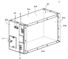
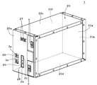
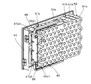
- FIG. 1 is a perspective view illustrating an external appearance of the power storage device.
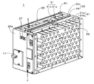
- FIG. 2 is a perspective view in which the top plate and the front side plate of the power storage device are omitted.
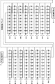
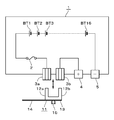
- FIG. 3 is a block diagram illustrating an outline of an electrical configuration of the power storage device according to the first embodiment of the present technology.
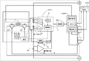
- FIG. 4 is a block diagram illustrating an example of an electrical configuration of the power storage device according to the first embodiment of the present technology.
- FIG. 5 is a perspective view showing the appearance of the power storage device with the short bar removed.
- FIG. 6 is a block diagram illustrating an outline of an electrical configuration of the power storage device according to the first embodiment of the present technology.
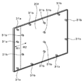
- FIG. 7 is a perspective view illustrating a configuration example of the side plate.
- FIG. 1 is a perspective view illustrating an external appearance of the power storage device.
- FIG. 2 is a perspective view in which the top plate and the front side plate of the power storage device are omitted.
- FIG. 3 is a block diagram
- FIG. 8A is a perspective view illustrating a configuration example before the battery unit is combined with the side plate.
- FIG. 8B is a perspective view illustrating a configuration example in a state where the battery unit is fixed to the side plate.
- FIG. 9 is a perspective view illustrating a configuration example in a state where the battery unit and the fuse substrate are fixed to the side plate.
- FIG. 9B is a plan view of the battery unit in which the sub-board is fixed to the battery case.
- FIG. 10 is a perspective view showing a configuration example in a state where the battery unit and the output terminal board are fixed to the side plate.
- FIG. 11 is a perspective view illustrating a configuration example in a state in which the front plate and the rear plate of the exterior case are omitted.
- FIG. 12 is a perspective view for explaining the structure of the resin plate.
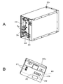
- FIG. 13A is a perspective view illustrating a configuration example in a state where a front plate of the exterior case is removed.
- FIG. 13B is a perspective view illustrating a configuration example of the front plate removed from the exterior case.
- FIG. 14 is a perspective view showing a configuration example of the battery unit.
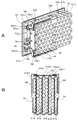
- FIG. 15A is a perspective view illustrating a configuration example of a top case.
- FIG. 15B is a perspective view illustrating a configuration example of the bottom case.
- FIG. 16A is an enlarged view of a region Q1 in FIG. 15A.
- FIG. 16B is an enlarged view of a region Q2 in FIG. 15B.
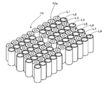
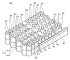
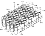
- FIG. 17 is a perspective view in which components other than the battery block group are omitted from the battery unit shown in FIG. 14.
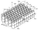
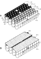
- 18A is a perspective view in which the top case is omitted from the battery unit shown in FIG. 18B is a perspective view in which tabs are further omitted from the configuration of FIG. 18A.
- FIG. 19 is a perspective view in which the tab and the insulating sheet are further omitted from the configuration of FIG. 18B.
- FIG. 20A is a perspective view illustrating a configuration example of a partition plate.
- FIG. 20B is a perspective view illustrating a configuration example of a partition plate.
- FIG. 21 is a partially enlarged perspective view of a notch portion of the partition plate.
- FIG. 22A shows a configuration in which the battery block group and the partition plate are omitted from the configuration of FIG.
- FIG. 22B is a configuration in which the positive electrode insulating sheet is omitted from the configuration of FIG. 22A.
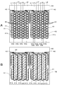
- FIG. 23A is a plan view schematically illustrating the power storage device.
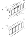
- FIG. 23B is a plan view schematically showing the power storage device. It is a perspective view which shows the structural example which provided the thermal radiation rubber in the bottom case.
- FIG. 25 is a perspective view in which the top case, the tab, and the positive electrode insulating sheet are omitted from the battery unit.
- FIG. 26A is a perspective view in which the top case and the tab are omitted from the battery unit.
- FIG. 26B is a perspective view in which the top case is omitted from the battery unit.
- FIG. 27 is a perspective view in which the top case, the tab, and the positive electrode insulating sheet are omitted from the battery unit.
- FIG. 28A is a perspective view in which the top case and the tab are omitted from the battery unit.
- FIG. 28B is a perspective view in which the top case is omitted from the battery unit. It is a block diagram for demonstrating the application example of the electrical storage apparatus of this technique. It is a block diagram for demonstrating the application example of the electrical storage apparatus of this technique.
- FIG. 1 is a perspective view illustrating an external appearance of the power storage device.
- FIG. 2 is a perspective view in which the top plate and the front side plate of the power storage device are omitted.
- FIG. 3 shows an outline of the electrical configuration of the power storage device according to the first embodiment of the present technology.
- FIG. 4 shows an outline of the electrical configuration of the power storage device according to the first embodiment of the present technology.
- FIG. 5 shows the appearance of the power storage device with the short bar removed.
- FIG. 6 shows an outline of the electrical configuration of the power storage device according to the first embodiment of the present technology.
- the power storage device 1 includes an exterior case 20.
- the exterior case 20 is a substantially rectangular parallelepiped casing composed of a front plate 20a, a back plate 20b, an upper plate 20c and a lower plate 20d, and two side plates 20e and 20f.
- battery unit 51 and battery unit 52, insulating material 55 interposed between battery unit 51 and battery unit 52, a control circuit block, and the like are provided in exterior case 20 of power storage device 1.
- a mounted substrate (not shown in FIG. 2) and the like are accommodated.
- Each of the battery unit 51 and the battery unit 52 includes a battery block group and a member such as a tab that electrically connects a plurality of battery cells accommodated in a battery case 61 in which a top case 61a and a bottom case 61b are combined. It is.
- the battery block group is composed of, for example, a plurality of battery blocks connected in series, and one battery block is composed of a plurality of battery cells connected in parallel.
- the battery cell is a secondary battery such as a cylindrical lithium ion secondary battery. The battery cell is not limited to a lithium ion secondary battery.
- the battery unit 51 and the battery unit 52 are stacked in two stages in the horizontal direction and are accommodated in the outer case 20 with the bottom surface and the top surface of the top case 61a vertically placed in the horizontal direction.
- the battery unit 51 and the battery unit 52 contain battery blocks B1 to B16 formed of 10 battery cells connected in parallel and connected in series.
- the battery unit 51 accommodates a battery block group composed of battery blocks B1 to B8.
- the battery unit 52 accommodates a battery block group composed of battery blocks B9 to B16.
- the number of battery cells constituting each battery block is not limited to ten, and the number of battery blocks constituting the battery block group is not limited to the above.
- a tab which is a member having electrical conductivity for connection is used.
- the tab is a plate-like body made of a material having electrical conductivity such as metal.
- a control block is provided in the power storage device 1 in order to monitor the voltage, current, and temperature of the battery cell. Information from the control block is transmitted by communication to an external controller.
- An external controller performs management for charge management, discharge management, deterioration suppression, and the like.
- the control block monitors the voltage of each battery block, converts the detected voltage into a digital signal, and transmits the digital signal to the control box ICNT which is an external controller.
- the temperature of each battery block may be detected, converted into digital data, and transmitted to the control box ICNT.
- Fig. 4 shows an example of the control block. As shown in FIG. 4, the voltage at both ends of 16 battery blocks B1 to B16 connected in series and the voltage of each battery block are detected.
- a multiplexer 8 (MUX8) is provided for sequentially outputting the voltage across the battery blocks B1 to B16 and the voltage of each battery block.
- the MUX 8 switches channels according to a predetermined control signal, for example, and selects one analog voltage data from n analog voltage data.
- One analog voltage data selected by the MUX 8 is supplied to an A / D converter (ADC (Analog-to-Digital Converter) 6).
- ADC Analog-to-Digital Converter
- the ADC 6 converts the analog voltage data supplied from the MUX 8 into digital voltage data. For example, analog voltage data is converted into digital voltage data of 14 to 18 bits. Digital voltage data from the ADC 6 is supplied to the communication unit COM1.
- the communication unit COM1 is controlled by the control unit 7 and communicates with an external device connected through a communication terminal. For example, communication with another power storage device MO is performed through the communication terminal, and communication with the control box ICNT is performed through the communication terminal. Further, it receives a control signal from the control box ICNT through the communication terminal.
- the communication unit COM1 performs bidirectional communication.
- control unit 7 controls the equalization of the voltages of the battery blocks B1 to B16.
- Such control is referred to as cell balance control.
- cell balance control For example, when one battery block among the plurality of battery blocks B1 to B16 reaches the discharge voltage at the lower limit of use, there is another battery block that still has capacity. When the battery is next charged, the other battery blocks having the remaining capacity quickly reach the charging upper limit voltage and cannot be charged until fully charged. In order to avoid such an imbalance, the remaining battery block is forcibly discharged by turning on a MOSFET (Metal / Oxide / Semiconductor / Field / Effect / Transistor).
- MOSFET Metal / Oxide / Semiconductor / Field / Effect / Transistor
- a control pulse is supplied from the pulse generator 17 to the primary switch (MOSFET) S1 of the flyback transformer T1 of the module balance control circuit that controls the voltage balance between the power storage device 1 and the plurality of power storage devices MO.
- the pulse generator 17 generates a control pulse according to a control signal from the control unit 7 of the module controller CTN1. For example, the pulse generator 17 outputs a control pulse subjected to pulse width modulation.
- a control pulse for the secondary side switch (MOSFET) S01 of the flyback transformer T1 is supplied from an MCU (MIcroController Unit) in the communication unit COM1.
- Control box ICNT determines the balance sequence between the power storage devices from the voltage information of each power storage device 1 and power storage device MO. The presence / absence of charge / discharge of the balance between the power storage devices is individually transmitted to the MCU of each power storage device. The MCU directly supplies a control signal to the secondary side of the flyback transformer, or transmits the control signal to the primary side of the flyback transformer T1 by insulating communication via the insulating unit ISC1.
- the temperature detection unit 15 includes a temperature detection element such as a thermistor.
- Analog temperature data T indicating the temperature of each of the battery blocks B1 to B16 detected by the temperature detector 15 is supplied to the cell temperature multiplexer 16 (MUX16).
- MUX16 cell temperature multiplexer 16
- analog temperature data T1 indicating the temperature of the battery block B1 is supplied to the MUX 16.
- analog temperature data T2 indicating the temperature of the battery block B2 is supplied to the MUX 16.
- analog temperature data T3 to analog temperature data T16 indicating the temperatures of the battery blocks B3 to B16 are supplied to the MUX 16.
- MUX 16 switches channels according to a predetermined control signal, and selects one analog temperature data T from 16 analog temperature data T1 to analog temperature data T16. Then, one analog temperature data T selected by the MUX 16 is supplied to the ADC 6.
- the current detection unit 9 detects the current value flowing through the plurality of battery blocks B1 to B16.
- the current detection unit 9 includes, for example, a current detection resistor 9a and a current detection amplifier 9b.
- the analog current data indicating the voltage value at both ends of the current detection resistor 9a is detected by the current detection resistor 9a.
- the analog current data is always detected regardless of whether it is being charged or discharged.
- the analog current data may be detected at a predetermined cycle.
- Detected analog current data is supplied to the current detection amplifier 9b.
- the supplied analog current data is amplified by the current detection amplifier 9b.
- the amplified analog current data is supplied to the ADC 6.
- the ADC 6 converts the analog current data supplied from the current detection amplifier 9b into digital current data.
- the ADC 6 converts the analog current data into digital current data, and outputs the digital current data.
- the switch (not shown) when the module controller CTN1 detects that an excessive current flows during discharging, it is determined as a discharging overcurrent state, and the switch (not shown) is controlled to be in an open state (a state where current is cut off). To do. On the other hand, when it is detected that an excessive current flows during charging, the switch (not shown) is controlled to an open state (a state where the current is cut off).
- the insulating unit ISC1 has a function of insulating between the communication unit COM1 and the module controller CTN1. That is, the reference potential of the power source of the communication unit COM1 and the reference potential of the power source of the module controller CTN1 are separated and made independent. Furthermore, in an insulated state, the insulating unit ISC1 has a function of supplying a power supply voltage to the module controller CTN1 and a function as a transmission medium for bidirectional communication.
- the CAN standard can be used as a bidirectional communication method performed through the insulating unit ISC1.
- a power transmission method performed through the insulating portion ISC1 an electromagnetic induction method, a magnetic field resonance method, a radio wave reception method, or the like can be used.
- a non-contact IC card technology performs communication and power transmission between the reader / writer and the card by magnetically coupling the antenna coil of the reader / writer and the antenna coil of the card.
- the communication uses a method of ASK (Amplitude Shift ⁇ Keying) modulation of a carrier wave having a frequency of 13.56 kHz, and a speed of 212 or 424 kbps is performed.
- the insulating part ISC1 has the same specifications as the non-contact IC card method. Further, for example, the insulating portion ISC1 performs communication and power transmission between antennas (coils) formed in different layers of the multilayer printed board.
- An external positive terminal 4 and an external negative terminal 5 for charging / discharging the power storage device 1 are provided on the front surface of the power storage device 1.
- the external positive terminal 4 and the external negative terminal 5 are preferably provided so as not to overlap in the vertical direction, for example. This is because when the connection member for connecting to another power storage device is connected to the external positive electrode terminal 4 and the external negative electrode terminal 5, the connection members can be prevented from overlapping.
- windows 25 and 26 are further formed close to the front plate 20 a of the power storage device 1. Furthermore, a connector 27 that is a communication terminal for communication with an external controller is provided on the front surface of the power storage device 1. As described above, the power storage device 1 is provided with a control block that monitors battery voltage, current, and temperature. Information from the control block is transmitted by communication to an external controller. An external controller performs management for charge management, discharge management, deterioration suppression, and the like.
- a serial interface is used for communication with an external controller via the connector 27.
- an SM bus System Management Bus
- an I2C bus can be used as the serial interface.
- the I2C bus is synchronous serial communication in which communication is performed using two signal lines of SCL (serial clock) and bidirectional SDA (serial data).
- Connectors 3a and 3b are erected on the inner side of the window 25 formed on the front plate 20a.
- the terminals on the positive side of the battery blocks B1 to B16 connected in series are connected to the connector 3a via the fuse 2 which is a current interruption element.
- the other connector 3b is provided in the vicinity of the connector 3a.
- the connector 3b is connected to the external positive terminal 4.
- Terminals on the negative side of the battery blocks B1 to B16 are connected to the external negative terminal 5.
- a short bar 11 that can be freely inserted and removed is provided as a connecting portion to the connectors 3a and 3b.
- the short bar 11 has a configuration in which a conductive plate is bent so as to have a pair of plate-like protrusions 12 a and 12 b, and a base portion of the conductive plate is attached to one surface of the support plate 13.
- the cover 14 is formed by extending one end of the support plate 13. Further, a knob 15 is formed on the other surface of the support plate 13.
- the support plate 13 having the cover 14 and the knob 15 is, for example, a synthetic resin molded product.
- Each of the connectors 3a and 3b has two spring contact plates arranged to face each other, and the plate-like protrusions 12a and 12b of the short bar 11 are inserted through the window 25 into the gap between the two spring contact plates. It is made like that. Further, the window 26 is closed by the cover 14 integrated with the support plate 13 of the short bar 11. Since the plate-like protrusions 12a and 12b are sandwiched between the two spring contact plates of the connectors 3a and 3b, respectively, the insertion state of the short bar 11 can be maintained with respect to the connectors 3a and 3b.
- the connector 3a and the connector 3b are connected (conducted) by the short bar 11.
- the connector 3a and the connector 3b are disconnected (non-conductive).
- An electronic component for setting or connection is arranged inside the window 26 formed in the front plate 20a.
- the electronic components include, for example, a slide switch 28, a rotary switch 29, and a JTAG connector 30.
- An address for the power storage device 1 is set by the rotary switch 29. That is, a plurality of power storage devices 1 can be connected and used, and when a plurality of power storage devices 1 are connected, an identification address is set for each power storage device.
- An external controller performs control processing based on this address.
- the slide switch 28 is used to increase the address designated by the rotary switch 29.
- the JTAG connector 30 is a standard connector proposed by JTAG (Joint European Test Action). Test data is input / output through the JTAG connector 30 to inspect the MPU (Micro Processing Unit), IC (Integrated Circuit), etc. inside the case, and the firmware of the internal MPU is rewritten. In addition, as an electronic component, you may use switching components other than the element mentioned above, a connector, etc.
- the cover 14 closes the windows 25 and 26 in front of the operation surface of the electronic component. That is, in the connected state, access to the electronic component is blocked.
- a window in front of the operation surface of the setting unit is opened, and the operation surface can be operated through the windows 25 and 26 to set the address of the power storage device 1, for example.
- the operation surface can be accessed and the electronic component can be set.
- workability can be improved and safety can be improved as compared to operating the electronic component inside the case.
- the plate-like body constituting the outer case 20 is a metal plate such as aluminum, an aluminum alloy, copper, or a copper alloy.
- a front side surface of the outer case 20 is configured by a side plate 20e, and a back side surface is configured by a side plate 20f.
- the side plate 20e and the side plate 20f are, for example, rectangular plate-like bodies.
- the rectangular plate-like body is preferably a metal plate made of a metal material such as aluminum.
- the side plate 20f is divided into a board placement area R1 where the board is placed and a battery unit placement area R2 where the battery unit 51 is placed, with a dotted line as a boundary.
- a plurality of protrusions 31a for positioning and fixing the substrate and a plurality of protrusions 31b for positioning and fixing the battery unit 51 are provided on one main surface inside the side plate 20f.
- the protrusions 31a are provided in a row in the direction perpendicular to the substrate arrangement region R1.
- the protrusion 31b is provided at the peripheral end of the battery unit arrangement region R2.
- the protrusions 31b are provided in a row in the vertical direction at a substantially central portion of the battery unit arrangement region R2.
- the side plate 20e is similarly provided with a plurality of protrusions 31a for positioning and fixing the substrate, and for positioning and fixing the battery unit 52 at a predetermined position on one inner main surface.
- a plurality of protrusions 31b are provided.
- the plurality of protrusions 31a are provided in a row in the vertical direction in the substrate arrangement region R1, for example.
- the plurality of protrusions 31b are provided, for example, at the peripheral end of the battery unit arrangement region R2.
- the protrusions 31b are provided in a row in the vertical direction at a substantially central portion of the battery unit arrangement region R2.
- the battery unit 51 is arranged in the battery unit arrangement region R2 of the side plate 20f.
- the plurality of protrusions 31b are respectively fitted into the plurality of holes 41b of the bottom case 61b corresponding to the positions, and the battery unit 51 is fixed to a predetermined position of the side plate 20f.
- illustration is abbreviate
- the eight protrusions 31b provided at the peripheral end portion of the battery unit arrangement region R2 include eight holes 41b provided at the peripheral end portion of the bottom surface portion of the bottom case 61b (note that the hole 41b Are partially fitted).
- the four protrusions 31b at the substantially central portion of the battery unit arrangement region R2 are respectively fitted into holes (not shown) on the bottom surfaces of the plurality of hollow structures provided in a row on the bottom case 61b. Accordingly, screwing is performed, and the battery unit 51 is fixed to a predetermined position of the side plate 20f.
- the fuse substrate 43 on which the circuit including the fuse 2 and the connectors 3a and 3b is mounted is arranged and fixed to the side plate 20f in which the battery unit 51 shown in FIG. 8B is arranged and fixed.
- the plurality of protrusions 31a of the side plate 20f are respectively fitted into the plurality of holes 41a provided in the fuse substrate 43 corresponding to the positions, and as shown in FIG. 9A, the fuse substrate 43 is positioned at a predetermined position of the side plate 20f. Fixed to.
- the sub-board 42 is fixed to the battery unit 51.
- one main surface of the sub-board 42 faces one wall surface orthogonal to the column direction of the battery row in the four wall surfaces of the battery case 61, and a part thereof
- the sub-board 42 is disposed and fixed so as to be in close contact with each other. Thereby, a useless space for arranging the sub-board 42 can be reduced.
- Screw terminal portions 42a1 are provided at both end portions of the sub-board 42.
- the end portion of the connection bar 98 that is joined to the tab 91a and is shaped like a plate and bent at a right angle is joined to the screw terminal portion 42a1 of the sub-board 42.
- an opening 48 through which the protruding end portion 91b1 of the tab is led out is provided on one wall surface of the battery case.
- the protruding end portions 91b1 protruding in a rectangular shape of the three tabs 91b pass through the opening portion 48 of one wall surface and are directly inserted into the upper end portion of the sub-board 42 and connected.
- the protruding end 91b1 of the tab 91b provided on the lower surface side of the battery block group 10 similarly passes through the opening 48 on one wall surface and directly pierces the lower end of the sub-board 42. Connected.
- a member for example, a plurality of lead wires for connecting each of the battery blocks B1 to B8 and the sub board 42 can be omitted.
- connection member 47a1 is, for example, a plate-like body made of a metal material having electrical conductivity. (The same applies to the connecting members 47a2 and 47a3 described below.)
- FIG. 10 is a perspective view showing a state where the battery unit 52 and the output terminal board 44 are arranged and fixed at predetermined positions on the side plate 20e.
- a plurality of projections 31b (not shown) provided on the side plate 20e are provided with a plurality of holes 41b (some of the holes are not shown) provided in the bottom case 61b corresponding to the positions.
- the battery unit 52 is fixed to a predetermined position of the side plate 20e.
- the plurality of protrusions 31a provided on the side plate 20e are respectively fitted into a plurality of holes (not shown) provided in the output terminal substrate 44 corresponding to the positions, and the output terminal substrate 44 is connected to the side plate. It is fixed at a predetermined position of 20e.
- connection member 47a2 is joined to the screw terminal portion 42a1 of the sub-board 42, the other end is joined to the output terminal board 44, and the sub-board 42 and the output terminal board 44 are electrically connected via the connection member 47a2.
- connection member 47a3 whose one end is bonded to the output terminal substrate 44 is bonded to the screw terminal portion 42b2 (shown in FIG. 9A) of the fuse substrate 43, and the output terminal substrate 44 and the fuse substrate 43 are connected to the connection member 47a3. It is electrically connected via. (The joined state is shown in FIG. 11 described later.)
- FIG. 11 is a perspective view of the power storage device in which the front plate, the back plate, the top plate, and the bottom plate are omitted.
- the combination unit U ⁇ b> 1 and the combination unit U ⁇ b> 2 face each other with an insulating material 55 interposed therebetween.
- the combination unit U1 is a unit in which the battery unit 51 and the fuse substrate 43 to which the sub substrate 42 is fixed are fixed to the side plate 20f.
- the combination unit U2 is a unit in which a battery unit 52 and an output terminal board 44 to which a sub board 42 (not shown) is fixed are fixed to the side plate 20e.
- the insulating material 55 is provided to ensure insulation between the two battery units 51 and 52 facing each other or to further improve the insulation.
- the insulating material 55 is interposed between the two battery units 51 and 52 facing each other.
- the insulating material 55 is composed of, for example, two rectangular resin plates 53 and a resin plate 54 that are in close contact with each other.
- the resin plate 53 is overlaid on the bottom surface of the top case 61 a of the battery unit 51.
- the resin plate 54 is overlaid on the bottom surface of the top case 61 a of the battery unit 52.
- the insulating material 55 may be composed of a single resin plate. Moreover, the laminated structure of three or more resin plates may be sufficient. Moreover, it is good also as a laminated structure of a resin plate and a metal plate, such as providing one metal plate between two resin plates. In this case, it is possible to ensure high insulation and to further improve heat dissipation.
- the high insulation between the battery unit 51 and the battery unit 52 is ensured when the opening which the tab provided in the battery unit 51 exposes is covered with another insulating material, it replaces with the insulating material 55.
- a member with high heat dissipation for example, a metal plate such as an Al plate
- the heat dissipation of the power storage device 1 can be further improved.
- the resin plate 53 has, for example, a plurality of protrusions 56a, a plurality of recesses 56b, a plurality of grooves 57, and a plurality of holes 59 for leading out the thermistor cords 58. Is provided.
- the resin plate 54 facing the resin plate 53 is similarly provided with a plurality of protrusions 56a, a plurality of recesses 56b, a plurality of grooves 57, and a thermistor cord 58.
- a hole 59 is provided.
- the two protrusions 56a and the two recesses 56b are provided for positioning when the combination units U1 and U2 are combined through the resin plate 53 and the resin plate 54.
- the projection 56a of the resin plate 53 and the recess 56b of the resin plate 54 are fitted, and the recess 56b of the resin plate 53 and the projection 56a of the resin plate 54 are fitted. Is done.
- the thermistor cord 58 can be stored in the plurality of grooves 57 provided in the resin plate 53 and the resin plate 54, and the resin plate 53 and the resin plate 54 are excellent in cord storage property.
- FIG. 13A is a perspective view of the outer case 20 with the front plate removed.
- FIG. 13B is a perspective view showing the front plate removed from the exterior case 20.
- a space for accommodating the substrate is secured on the inner surface side of the front plate 20a, and a monitor substrate 45 is provided in this space as shown in FIG. 13B.
- the control board including the monitoring and control circuit shown in FIGS. 3 and 4 is mounted on the monitor board 45 and the sub board 42 described above.
- the communication unit COM1 is mounted on the monitor substrate 45
- the module controllers CTN1, MUX16, the current detection unit 9, the flyback transformer T1, and the insulating unit ISC1 are mounted on the sub-board 42.
- the circuit including the fuse 2 and the connectors 3a and 3b through which a large current flows and the circuit including the output terminal are separated from the monitor board 45 and the sub board 46 mounted with the control block including the monitoring and control circuit.
- the circuit board is mounted on a substrate (a fuse substrate 43 and an output terminal substrate 44).
- the data communication of the monitoring and control circuit unit is not affected by noise disturbances and influences associated with current and power, and is not affected by heat generation of a large current, thereby improving reliability.
- a separate substrate group (sub-substrate 42, fuse substrate 43, output terminal substrate 44, monitor substrate 45) is arranged in a space between the inner surface of the front plate 20a and one wall surface of the battery case 61. And since each is connected by the plate-shaped connection member, the connection of board
- FIG. 14 is a perspective view showing the external appearance of the battery unit.
- the battery unit 51 is a battery case 61 in which a later-described battery block group 10, a partition plate 93a, a partition plate 93b, tabs 91a and 91b, and a positive electrode insulating sheet 92 are accommodated.
- the battery unit 52 has the same configuration as the battery unit 51. Therefore, hereinafter, the configuration of the battery unit 51 will be described in detail, and the detailed description of the configuration of the battery unit 52 will be omitted.
- the battery case 61 includes a top case 61a and a bottom case 61b.
- FIG. 15A is a perspective view illustrating a configuration example of a top case.
- FIG. 15B is a perspective view illustrating a configuration example of the bottom case.
- the battery case 61 is a resin molded product made of a resin having electrical insulation, for example.
- the top case 61a includes an upper surface portion and a wall portion erected around the upper surface portion.
- Three hollow structures 70 are provided in a row at the center of the upper surface portion.
- the hollow structure 70 is, for example, a hollow structure and a hollow cylindrical structure having an upper surface and a lower surface that are open.
- FIG. 16A is an enlarged view of a region Q1 in FIG. 15A.
- the upper surface portion is provided with a plurality of openings 71 through which tabs 91a or tabs 91b described later are exposed.
- the upper surface portion is provided with a plurality of holes 72 into which protrusions 94 of a partition plate 93 described later are fitted.
- a thermistor insertion hole 73 is provided in the upper surface portion.
- one thermistor insertion hole 73 is provided at each of the four corners of the upper surface, and four are provided near the center.
- the bottom case 61b includes a bottom surface portion and a wall portion erected around the bottom surface portion.
- four hollow structures 80 are provided in a row at the center of the bottom surface.
- the hollow structure 70 is, for example, a hollow cylindrical structure that has a hollow structure, an upper surface that is open, and a hole 41b at the center of the lower surface. As described above, the hole 41b engages with the protrusion 31b provided on the side plate 20f, and is screwed or the like as necessary, so that the battery unit 51 is fixed to the side plate 20f.
- FIG. 16B is an enlarged view of region Q2 in FIG. 15B.
- the bottom surface portion is provided with a plurality of openings 81 through which tabs 91b described later are exposed.
- a plurality of holes 82 are provided on the bottom surface portion, into which projections 94 of a partition plate 93 described later are fitted.
- (Internal configuration of battery unit) (Battery block group) 17 is a perspective view in which components other than the battery block group are omitted from the battery unit shown in FIG.
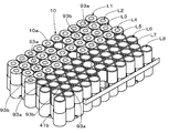
- the battery block group 10 accommodated in the battery case 61 is composed of a plurality of battery cells 10a.
- the battery block group 10 has, for example, a configuration in which battery rows L1 to L8 including a plurality of battery cells 10a arranged in a straight line are juxtaposed in a direction substantially orthogonal to the row direction of the battery rows. .
- Each of the battery rows L1 to L8 includes, for example, 10 batteries.
- the plurality of battery cells 10a constituting the battery block group 10 are electrically connected by tabs 91a and 91b described later.
- each of the battery rows L1 to L8 constitutes battery blocks B1 to B8 in which a plurality of battery cells 10a are connected in parallel. Further, the battery blocks B1 to B8 are connected in series to constitute the battery block group 10.
- each of the battery rows L1 to L8 constitutes battery blocks B9 to B16 in which a plurality of battery cells 10a are connected in parallel. Further, the battery blocks B9 to B16 are connected in series to constitute the battery block group 10.
- a plurality of battery rows (battery rows L1 to L8) to which a plurality of battery cells 10a are connected in parallel are juxtaposed in a direction substantially orthogonal to the row direction, and these are connected in series.
- the current path can be rectified in a single direction (for example, a direction substantially orthogonal to the column direction of the battery array) and the total length of the current path can be shortened, and as a result, an increase in resistance can be suppressed.
- FIG. 18A is a perspective view in which the top case is omitted from the battery unit shown in FIG.
- tabs 91a and tabs 91b which are joining members that electrically connect the plurality of battery cells 10a, are provided on the terminal surfaces of the plurality of battery cells 10a.
- two tabs 91a and three tabs 91b are juxtaposed in a direction substantially orthogonal to the row direction of the battery row.
- the tab 91b is provided with a plurality of holes 96 through which the projections 94 of the partition plate 93 are inserted.
- the tab 91a is electrically joined to the terminal surfaces of the plurality of battery cells 10a constituting one battery row.
- the tab 91b is electrically joined to the terminal surfaces of the plurality of battery cells 10a constituting two adjacent battery rows.
- the tab 91a is electrically joined to the positive terminals of the plurality of battery cells 10a constituting the battery row L1.
- the tab 91a is electrically joined to the positive terminals of the plurality of battery cells 10a constituting the battery row L8.
- the tab 91b is electrically joined to the negative terminals of the plurality of battery cells 10a constituting the battery row L2 and the positive terminals of the plurality of battery cells 10a constituting the battery row L3.
- the tab 91b is electrically joined to the negative terminals of the plurality of battery cells 10a constituting the battery row L4 and the positive terminals of the plurality of battery cells 10a constituting the battery row L5.
- the tab 91b is electrically joined to the negative terminals of the plurality of battery cells 10a constituting the battery row L6 and the positive terminals of the plurality of battery cells 10a constituting the battery row L7.
- the joining method includes, for example, electric resistance welding or welding by laser light heating, but is not particularly limited to these methods, and conventionally known welding methods can be appropriately used.
- the resistance value can be reduced and the terminal heat generation can be reduced.
- the tabs can be joined by simple joining.
- the measurement terminal of the battery cell 10a can also be shared. Since the plurality of battery cells 10a constituting the battery array are joined with one tab, the assembling work can be simplified, and the working efficiency at the time of assembling can be improved. In addition, since the number of joints can be reduced, the heat rise of the battery cell 10a at the time of assembly joining can be reduced. The heat generated when the battery cell 10a is charged and discharged can be conducted to the tab 91a and the tab 91b to radiate heat.
- FIG. 18B is a perspective view in which tabs are further omitted from the configuration of FIG. 18A.
- a positive electrode insulating sheet 92 is overlaid on the positive electrode terminal surface of the battery cell 10a constituting the battery block group 10.
- the positive electrode insulating sheet 92 is overlaid on the positive electrode terminal surface of the battery cell 10a whose upper surface is the positive electrode terminal surface.
- the positive electrode insulating sheet 92 is overlaid on the positive electrode terminal surfaces of the plurality of battery cells 10a that respectively form the battery row L1, the battery row L3, the battery row L5, and the battery row L7.
- the positive electrode insulating sheet 92 is made of an electrically insulating material such as an electrically insulating resin material.
- the positive electrode insulating sheet 92 is provided with a plurality of openings 97 into which a plurality of convex positive terminals are fitted.
- Each positive electrode terminal is fitted into each of the plurality of openings 97 of the positive electrode insulating sheet 92, and each positive electrode terminal is exposed from the opening 97 of the positive electrode insulating sheet 92.
- the positive electrode terminal exposed from the opening 97 of the positive electrode insulating sheet 92 and the tab 91a or the tab 91b are electrically joined.
- the surface around the positive electrode terminal is covered with the positive electrode insulating sheet 92, whereby the surface around each positive electrode terminal and the tab 91a or the tab 91b are insulated.
- FIG. 19 is a perspective view in which the tab and the insulating sheet are further omitted from the configuration of FIG. 18B.
- a plurality of battery rows L1 to L8 are juxtaposed in a direction substantially orthogonal to the row direction of the battery rows to constitute a battery block group 10.
- the battery row L1 and the battery row L2 are arranged to face each other, the battery row L2 and the battery row L3 are arranged to face each other, the battery row L3 and the battery row L4 are arranged to face each other, and the battery row L4 and the battery row
- the row L5 is arranged to face the battery row
- the battery row L5 and the battery row L6 are arranged to face each other
- the battery row L7 and the battery row L8 are arranged to face each other.
- the plurality of battery cells 10a constituting each battery row are arranged such that the upper surface is a positive electrode terminal surface and the lower surface is a negative electrode terminal surface.
- the plurality of battery cells 10a constituting each battery row are arranged such that the upper surface is a negative electrode terminal surface and the lower surface is a positive electrode terminal surface.
- the plurality of battery cells 10a constituting each battery row are juxtaposed in a straight line and in a close state.
- ten battery cells 10a constituting each battery row are juxtaposed in a straight line and in a close state.
- the plurality of battery cells 10a constituting each battery row are formed of two sets of the plurality of battery cells 10a arranged in a straight line and in a close state. It arrange
- the space corresponding to this single battery is preferably provided, for example, at a position facing the center of the adjacent and facing battery rows L1, L3, L5, or L7.
- the 10 battery cells 10a constituting each battery row are two sets of five arranged in a straight line and in close contact with each other. It arrange
- the space substantially corresponding to this single battery is provided, for example, at a position facing the center of the adjacent and facing battery rows L1, L3, L5, or L7.
- a hollow structure 80 of the bottom case 61b and a hollow structure 70 of the top case 61a (not shown in FIG. 19) facing the hollow structure 80 are fitted. Yes.
- the hole 41b is provided in the bottom surface of the hollow structure 80 of the bottom case 61b, and the protrusion 31b of the side plate 20f is fitted into the hole 41b, and is screwed as necessary.
- the battery unit 51 is fixed to 20f. By providing the fixing portion with the side plate 20f near the center of the battery unit 51, it is possible to suppress the swelling of the battery unit 51 near the center due to the displacement of the battery cells 10a constituting the battery block group 10 or the like. .
- adjacent battery rows are substantially the same length as the radius of the outer circumference of the battery cell 10a and are stacked in the row direction. It is supposed to be arranged. As indicated by the dotted line P, in the stacked arrangement, the one centered between the two battery cells 10a adjacent to one row and the approximate center of the end surfaces of the two adjacent battery cells 10a in one row It includes an arrangement in which the approximate center of the battery cell 10a in the other column next to the column is a substantially equilateral triangle.
- a larger number of battery cells 10a can be accommodated in the battery case 61 in a limited space. Therefore, the number of battery cells per area can be increased, and the energy density of power storage device 1 can be improved.
- the partition plate 93 a and the partition plate 93 b are fitted between adjacent battery rows of the battery block group 10.
- the partition plate 93 is, for example, a resin molded product made of an electrically insulating resin.
- the partition plate 93 is detachable from the battery case 61.
- the partition plate 93a includes a plurality of protrusions 93a on the upper surface and the lower surface, and the protrusions 93a are attached to and fitted into the battery case 61 by being fitted into the holes 72 and 82 of the battery case 61.
- the protrusion is removed from the battery case 61 by removing it from the hole.
- the partition plate 93a shown in FIG. 20A or the partition plate 93b shown in FIG. 20B is inserted between the opposing battery rows.
- a partition plate 93a is inserted between the battery rows L1 and L2 that face each other and are adjacent to each other.
- a partition plate 93b is inserted between the battery row L2 and the battery row L3 that face each other and are adjacent to each other.
- a partition plate 93a is inserted between the battery row L3 and the battery row L4 that are opposite to each other.
- a partition plate 93b is inserted between the opposite and adjacent battery rows L4 and L5.
- a partition plate 93a is inserted between the battery row L5 and the battery row L6 that are opposed to each other.
- a partition plate 93b is inserted between the battery row L6 and the battery row L7 that face each other and are adjacent to each other.
- a partition plate 93a is inserted between the battery row L7 and the battery row L8 that face each other and are adjacent to each other.
- the partition plate 93a has an upper surface and a lower surface, and two side surfaces connecting the upper surface and the lower surface.
- the partition plate 93a has a shape that can be fitted between adjacent and adjacent battery rows. Specifically, for example, it is formed into a shape that can be inserted between opposing and adjacent battery rows arranged in a stacked manner.
- each of the two side surfaces of the partition plate 93b includes a continuous curved surface shape in which a plurality of curved walls curved in a substantially semicircular arc shape or the like are connected.
- the continuous curved surface shape of the two side surfaces is a shape in which the connecting positions t1 and t2 of the curved wall are shifted from each other by a substantially semicircular arc shape by a substantially radius.
- the battery cell 10a is arrange
- the partition plate 93a is provided with a notch 95 for securing a thermistor accommodation or arrangement space.
- FIG. 21 is a partially enlarged perspective view of the notch 95 of the partition plate 93a.
- the cutout portion 95 is formed by cutting a part from each of the upper end portion and the lower end portion at a position where the curved walls are connected.
- one notch 95 is provided on each of the upper side and the lower side at positions (four locations) where adjacent curved walls are connected.
- the notch 95 is provided substantially vertically below the thermistor insertion hole 73 provided in the top case 61 a in a state where the partition plate 93 a is combined with the battery case 61, and accommodates the thermistor inserted into the hole 73. Secure space.
- the notch 95 of the partition plate 93a may be provided only on the upper side.
- a plurality of protrusions 94 are provided at predetermined positions on the upper and lower surfaces of the partition plate 93a.
- the plurality of protrusions 94 provided on the upper surface are fitted into the plurality of holes 72 for positioning the partition plate provided at predetermined positions of the top case 61a, and the plurality of protrusions 94 provided on the lower surface are It fits into a plurality of holes 82 for positioning the partition plate provided at predetermined positions of the bottom case 61b.
- the partition plate 93a is fixed between the top case 61a and the bottom case 61b.
- the partition plate 93b has an upper surface and a lower surface, and two side surfaces connecting the upper surface and the lower surface, like the partition plate 93a. Unlike the partition plate 93a, the partition plate 93b is not provided with a notch 95.
- the partition plate 93b has a shape that can be inserted between two opposing battery rows, like the partition plate 93a. Specifically, for example, it is formed into a shape that can be fitted between two opposing battery rows arranged in a stack.
- each of the two side surfaces of the partition plate 93b includes a continuous curved surface shape in which a plurality of curved walls curved in a substantially semicircular arc shape or the like are connected.
- the continuous curved surface shape of the two side surfaces is a shape in which the connecting positions t1 and t2 of the curved wall are shifted from each other by a substantially semicircular arc shape by a substantially radius.
- the partition plate 93b Like the partition plate 93a, the partition plate 93b includes a plurality of protrusions 94 at predetermined positions on the upper surface and the lower surface.
- the plurality of protrusions 94 on the upper surface are fitted in the plurality of holes 72 for positioning the partition plate provided at predetermined positions on the bottom surface of the top case 61a, and the plurality of protrusions 94 on the lower surface are the bottom case 61b.
- the partition plate 93b is fixed between the top case 61a and the bottom case 61b.
- a plurality of battery cells 10a can be arranged and fixed at predetermined positions by the fixed partition plates 93a and 93b.
- a battery block group in which a plurality of battery cells 10a are fixed in an optimum arrangement for high energy density without using a holder case or the like provided with a plurality of individual battery holders corresponding to one battery shape as in the prior art. 10 can be configured.
- the upper battery cell 10a is changed to the lower battery cell 10a.
- the force can be distributed over the entire battery block group 10 by dispersing the pressure and stress, such as reducing the applied load. Thereby, a deformation
- FIG. 22A shows a configuration in which the battery block group and the partition plate are omitted from the configuration of FIG. Similar to the positive insulating sheet 92 on the top case side, the positive insulating sheet 92 on the bottom case 61b side is for suppressing a short circuit between the peripheral surface of the convex positive terminal and the tab 91b.
- the positive insulating sheet 92 on the bottom case side is overlaid on the positive electrode terminal surfaces of the battery cells 10a of the battery row L2, the battery row L4, the battery row L6, and the battery row L8.
- FIG. 22B is a configuration in which the positive electrode insulating sheet is omitted from the configuration of FIG. 22A.
- a plurality of tabs 91b are juxtaposed on the inner surface of the bottom surface of the bottom case 61b in a direction substantially perpendicular to the row direction of the battery row.
- One tab 91b is electrically joined to a terminal on the lower surface of the battery cell 10a constituting two adjacent battery rows.
- the tab 91b is provided with a plurality of holes 96 through which the projections 94 of the partition plate 93 are inserted.
- the tab 91b is electrically joined to the negative terminals of the plurality of battery cells 10a constituting the battery row L1 and the positive terminals of the plurality of battery cells 10a constituting the battery row L2.
- the tab 91b is electrically joined to the negative terminals of the plurality of battery cells 10a constituting the battery row L3 and the positive terminals of the plurality of battery cells 10a constituting the battery row L4.
- the tab 91b is electrically joined to the negative terminals of the plurality of battery cells 10a constituting the battery row L5 and the positive terminals of the plurality of battery cells 10a constituting the battery row L6.
- the tab 91b is electrically joined to the negative terminals of the plurality of battery cells 10a constituting the battery row L7 and the positive terminals of the plurality of battery cells 10a constituting the battery row L8.
- Patent Document 1 Japanese Patent Laid-Open No. 2011-154811
- Patent Document 2 Japanese Patent Laid-Open No. 2011-154882
- Patent Document 3 Japanese Patent Application Laid-Open No. 2011-154883
- connection terminal plate is joined to the terminal surfaces of two adjacent battery rows housed in a battery holder, a plurality of battery cells constituting the battery row are connected in parallel, and a plurality of battery cells are connected.
- a configuration is described in which battery rows are connected in series and these are further accommodated in an exterior body.
- this battery system uses a battery holder whose main purpose is fixing battery cells, the space for the battery holder is large and the optimum configuration for obtaining a high energy density has not been adopted.
- the optimal arrangement of the battery cells and the fixing of the battery cells are not performed at the same time in order to obtain a high energy density as in the present technology.
- Patent Document 4 Japanese Patent Application Laid-Open No. 2011-175896 discloses an assembled battery configuration using a partition plate in which ribs are formed in a hollow structure in parallel with battery cell rows. This Patent Document 4 describes a configuration in which heat radiation on the surface of a cell can be efficiently performed by using a zigzag terminal that connects a plurality of cells as a connection terminal.
- connection terminal the connection terminal and the heat generation and limit current when performing a large current were not considered. Furthermore, no consideration was given to the strength and torsion of the terminal joint when subjected to vibration and impact, and the terminal joint strength was weak.
- Second Embodiment A configuration example of a power storage device according to a second embodiment of the present technology will be described.
- Two battery units 51 and 52 similar to those in the first embodiment are accommodated in an outer case 20 which is a substantially rectangular parallelepiped casing.
- the outer case 20 has a configuration in which two battery units 51 and 52 that are stacked in two stages in the horizontal direction are placed so that the bottom surface of the top case and the bottom surface of the bottom case are oriented in the vertical direction. Except for the above, it is almost the same as the first embodiment.
- detailed description of the same configuration as that of the first embodiment will be appropriately omitted.
- FIG. 23A is a schematic top view in which the top plate of the power storage device and the top case, tab, and positive electrode insulating sheet of the battery case are omitted.
- FIG. 23B is a top view in which the top plate of the power storage device and the top case of the battery case are omitted. Note that, in the power storage device according to the second embodiment, the upper surface plate and the lower surface plate of the outer case 20 are provided with the substrate positioning protrusions 31a and the battery unit 51 and the battery unit 52 positioning protrusions 31b. .
- the plurality of protrusions 31b provided on each of the upper surface plate and the lower surface plate are respectively fitted into the plurality of holes 41b of the battery case 61 corresponding to the positions and the holes 41b provided on the bottom surface portion of the battery case, for example.
- the battery case 61 is fixed at a predetermined position.
- a plurality of protrusions 31a provided on the upper surface plate and the lower surface plate have a plurality of holes (not shown) provided in the output terminal board (not shown) and the fuse board (not shown) corresponding to the positions. And the output terminal board and the fuse board are fixed at predetermined positions.
- the front plate and the lower plate are the same as those in the first embodiment.
- the two side plates are the same as the top plate and the bottom plate of the first embodiment.
- a battery block group 10 in which a plurality of battery cells 10a are arranged in a stacked manner is accommodated in a battery case 61.
- the battery row L1 and the battery row L2 are arranged to face each other
- the battery row L2 and the battery row L3 are arranged to face each other
- the battery row L3 and the battery row L4 are arranged to face each other
- the battery row L4 and the battery row The row L5 is opposed
- the battery row L5 and the battery row L6 are opposed
- the battery row L6 and the battery row L7 are opposed
- the battery row L7 and the battery row L8 are opposed.
- the plurality of battery cells 10a constituting each battery row are arranged such that the upper surface is a positive electrode terminal surface and the lower surface is a negative electrode terminal surface.
- the plurality of battery cells 10a constituting each battery row are arranged such that the upper surface is a negative electrode terminal surface and the lower surface is a positive electrode terminal surface.
- the plurality of battery cells 10a constituting each battery row are arranged side by side in a straight line and in a close state.
- the plurality of battery cells 10a constituting each battery row are formed of two sets of the plurality of battery cells 10a arranged in a straight line and in a close state. It is arranged so that a space corresponding to one battery cell 10a is provided between them.
- the hollow structure 80 of the bottom case 61b and the hollow structure 70 (not shown in FIG. 23) of the top case 61a facing the hollow structure 80 are fitted. Yes.
- partition plate 93a or partition plate 93b as in the first embodiment is inserted.
- a partition plate 93a is inserted between the battery row L1 and the battery row L2.
- a partition plate 93b is fitted between the battery rows L2 and L3.
- a partition plate 93a is inserted between the battery rows L3 and L4.
- a partition plate 93b is fitted between the battery rows L4 and L5.
- a partition plate 93a is fitted between the battery rows L5 and L6.
- a partition plate 93b is inserted between the battery rows L6 and L7.
- a partition plate 93a is inserted between the battery rows L7 and L8.
- Protruding portions 94 that are fitted into the holes 72 and 82 of the top case 61a and the bottom case 61b are provided on the upper and lower surfaces of the partition plate 93a. Similarly, on the upper and lower surfaces of the partition plate 93b, protrusions 94 that are fitted into the holes 72 and 82 of the top case 61a and the bottom case 61b are provided.
- a tab 91a and a tab 91b for connecting the battery cells 10a are provided. As shown in FIG. 23B, two tabs 91a and three tabs 91b are juxtaposed on the terminal surface of the battery cell 10a on the terminal surface of the battery cell 10a. Tab 91a is electrically joined with the terminal surface of battery cell 10a which constitutes one battery row. Tab 91b is electrically joined with the terminal surface of battery cell 10a which constitutes two adjacent battery rows.
- a positive electrode insulating sheet 52 is provided on the positive electrode terminal surface on the upper surface and lower surface of the battery block group 10, and the positive electrode insulating sheet 52 is convex. It is provided to insulate between the surface around the positive electrode terminal and the tab.
- the numerical values, structures, shapes, materials, raw materials, manufacturing processes and the like given in the above-described embodiments and examples are merely examples, and different numerical values, structures, shapes, materials, raw materials, and the like as necessary.
- a manufacturing process or the like may be used.
- the plurality of protrusions and the plurality of holes may be one protrusion and one hole.
- the power storage device of the first embodiment and the power storage device of the second embodiment may have the following configuration.
- the bottom case 61b constituting the battery case 61 may be configured such that a plurality of heat radiation rubbers 63 are provided on the outer surface of the bottom surface portion.
- a plurality of heat radiation rubbers 63 are provided on the outer surface of the bottom surface portion.
- one heat radiating rubber 63 is provided so as to cover the two openings 81 from which the tabs are exposed.
- the heat radiation rubber 63 is made of a material having good thermal conductivity, good shock absorption characteristics and heat resistance, for example, silicon.
- the heat radiation rubber 63 may have a configuration (for example, a stacked configuration) in which a heat conductive material having good heat conductivity and a buffer material having good heat resistance and shock absorption characteristics are combined.
- the heat radiation rubber 63 faces and contacts the side plates of the outer case 20 (the upper surface plate and the lower surface plate in the second embodiment) facing the outer surface of the bottom surface portion of the bottom case 61b.
- the heat conductivity from 61 to the exterior case 20 can be improved, and the heat dissipation can be further improved.
- the connection form of the battery cells is not limited to the examples of the first embodiment and the second embodiment.
- the partition plates 93a and 93b have a shape that can be inserted between opposing battery rows even when the upper and lower sides of the positive electrode terminal surface and the negative electrode terminal surface are reversed with the upper and lower directions of the battery cell 10a reversed. That is, the common partition plate 93a is used both when the positive electrode terminal surface of the battery cell 10a is the upper surface and the negative electrode terminal surface is the lower surface and when the positive electrode terminal surface of the battery cell 10a is the lower surface and the negative electrode terminal surface is the upper surface. And 93b can be used. Therefore, in the battery block group 10 accommodated in the battery unit, the upper and lower sides of the positive electrode terminal surface and the negative electrode terminal surface of the battery cell 10a can be freely switched to easily change the battery cell connection type.
- the upper and lower sides of the positive electrode terminal surface and the negative electrode terminal surface of the battery cell 10a of the battery block group 10 may be interchanged as in the following first example and second example.
- FIG. 25 is a perspective view in which the top case, the tab, and the positive electrode insulating sheet are omitted from the battery unit.
- FIG. 26A is a perspective view in which the top case and the tab are omitted from the battery unit.
- FIG. 26B is a perspective view in which the top case is omitted from the battery unit.
- the battery row L1 and the battery row L2 are arranged to face each other, the battery row L2 and the battery row L3 are arranged to face each other, and the battery row L3 and the battery row L4 are arranged to face each other.
- the battery row L4 and the battery row L6 are arranged to face each other, the battery row L5 and the battery row L6 are arranged to face each other, the battery row L6 and the battery row L7 are arranged to face each other, and the battery row L7 and the battery row L8 are arranged. Opposed.
- the plurality of battery cells 10a constituting each battery row are arranged such that the upper surface is a positive electrode terminal surface and the lower surface is a negative electrode terminal surface.
- the plurality of battery cells 10a constituting each battery row are arranged such that the upper surface is a negative electrode terminal surface and the lower surface is a positive electrode terminal surface.
- a positive electrode insulating sheet 92 is overlaid on the battery cell surface (the upper surface of the battery rows L1, L2, L5, and L6) serving as the positive electrode terminal.
- the positive electrode insulating sheet 92 is accumulated also on the battery cell surface (lower surface of battery row L3, L4, L7, L8) used as a positive electrode terminal.
- a tab 91c and a tab 91d for connecting the battery cells 10a are provided on the terminal surface of the battery cell 10a.
- two tabs 91c and one tab 91d are juxtaposed on the terminal surface of the battery cell 10a.
- the tab 91c is electrically joined to the terminal surfaces of the battery cells 10a constituting the two battery rows.
- the tab 91d is electrically joined to the terminal surfaces of the battery cells 10a constituting the four adjacent battery rows.
- a battery row L1 and a battery row L2 in which a plurality of battery cells 10a are connected in parallel constitute one battery block B1
- Constitutes one battery block B2 a battery row L5 in which a plurality of battery cells 10a are connected in parallel and a battery row L6 constitute one battery block B3, and a battery row L7 in which a plurality of battery cells 10a are connected in parallel.
- column L8 comprises one battery block B4.
- Battery blocks B1 to B4 are connected in series to constitute a battery block group 10.
- FIG. 27 is a perspective view in which the top case, the tab, and the positive electrode insulating sheet are omitted from the battery unit.
- FIG. 28A is a perspective view in which the top case and the tab are omitted from the battery unit.
- FIG. 28B is a perspective view in which the top case is omitted from the battery unit.
- the battery row L1 and the battery row L2 are arranged to face each other, the battery row L2 and the battery row L3 are arranged to face each other, and the battery row L3 and the battery row L4 are arranged to face each other.
- the battery row L4 and the battery row L6 are arranged to face each other, the battery row L5 and the battery row L6 are arranged to face each other, the battery row L6 and the battery row L7 are arranged to face each other, and the battery row L7 and the battery row L8 are arranged. Opposed.
- the plurality of battery cells 10a constituting each battery row are arranged such that the upper surface is a positive electrode terminal surface and the lower surface is a negative electrode terminal surface.
- the plurality of battery cells 10a constituting each battery row are arranged such that the upper surface is a negative electrode terminal surface and the lower surface is a positive electrode terminal surface.
- a positive electrode insulating sheet 92 is overlaid on the battery cell surface (the upper surface of the battery rows L1, L2, L3, and L4) serving as the positive electrode terminal.
- the positive electrode insulating sheet 92 is piled up also between the battery cell surface (lower surface of battery row L5, L6, L7, L8) used as a positive electrode terminal, and a tab.
- tabs 91e for connecting the battery cells 10a are provided on the terminal surfaces of the battery cells 10a.
- Two tabs 91e are juxtaposed on the terminal surface of the battery cell 10a on the terminal surface of the battery cell 10a.
- Each of the two tabs 91e is electrically joined to the terminal surfaces of the battery cells 10a constituting the four battery rows.
- the lower surface of the battery cell 10a is similarly joined by a tab.
- the battery row L1, the battery row L2, the battery row L3, and the battery row L3 in which a plurality of battery cells 10a are connected in parallel form one battery block B1, and the plurality of battery cells 10a are connected in parallel.
- the battery row L5, the battery row L6, the battery row L7, and the battery row L8 constitute one battery block B2.
- Battery blocks B1 and B2 are connected in series to form a battery block group 10.
- the number of battery units accommodated in the outer case 20 is two. It is not limited to one.
- the number of battery units accommodated in the outer case may be one, or three or more.
- the power storage device may be housed in the outer case 20 by being stacked in three or more levels in the horizontal direction with the bottom surface portion and the top surface portion of the top case 61a facing vertically. In this case, an insulating material is disposed between the battery units facing each other.
- the power storage device may be housed in the outer case 20 by being stacked in three or more levels in the horizontal direction with the bottom surface portion and the top surface portion of the top case 61a being placed in the vertical direction.
- the power storage device of the present technology can also have the following configuration.
- the battery unit is A battery case comprising a top case provided with one or more first holes in the bottom portion and a bottom case provided with one or more second holes in the bottom portion; A battery block group in which a plurality of battery rows made up of a plurality of battery cells housed in the battery case and arranged in a row are juxtaposed in a direction substantially orthogonal to the row direction and arranged in a stacked manner When, The battery block group and the battery case are housed in the battery case, and are inserted between the battery rows facing and adjacent to each other, and one or more first protrusions fitted in the one or more first holes are on the upper surface.
- a power storage device including a partition plate provided on the lower surface with one or more second protrusions provided and fitted in the one or more second holes.
- One or more third holes are further provided in the bottom surface of the bottom case of the one or more battery units facing the first surface; One or more third holes are further provided in the bottom surface of the bottom case of the one or more battery units facing the second surface; The one or more third protrusions are fitted into the one or more third holes, and the one or more battery units are fixed to the first surface.
- One or more fifth protrusions are further provided on the first surface, One or more sixth protrusions are further provided on the second surface, and one or more fifth holes are provided in the second substrate.
- the third substrate is provided with one or more sixth holes, The one or more fifth protrusions are fitted into the one or more fifth holes, and the second substrate is further fixed to the first surface of the exterior case, Any one of [5] to [6], wherein the one or more sixth protrusions are fitted in the one or more sixth holes, and the third substrate is further fixed to the second surface.
- the plurality of battery rows are linearly and closely contacted with the first battery row composed of the plurality of battery cells arranged in a straight line and in a close contact state, which are alternately arranged in a direction substantially orthogonal to the row direction.
- a second battery row provided with a space for approximately one battery cell between two sets of battery cells arranged in a state
- the top case further includes a structure that is fitted into a space corresponding to approximately one battery cell
- the power storage device according to any one of [1] to [8], wherein the bottom case further includes another structure that is fitted into a space corresponding to approximately one battery cell.
- One or more seventh protrusions are provided on one surface of the outer case, The one or more seventh holes are provided in a surface facing the one surface of the other structure, The power storage device according to [9], wherein the one or more seventh protrusions are fitted in the one or more seventh holes of the other structure.
- an insulating material interposed between one bottom surface portion of the top case of one of the battery units facing each other and another bottom surface portion of the top case of the other battery unit.
- the insulating material includes a first resin plate overlaid on the one bottom surface portion and a second resin plate overlaid on the other bottom surface portion, which are in close contact with each other,
- the first resin plate is provided with a protrusion and / or a recess on a surface in close contact with the second resin plate
- the second resin plate is provided with a protrusion and / or a recess on a surface in close contact with the first resin plate
- [17] [1] An electronic device that is supplied with electric power from the power storage device according to any one of [14].
- [18] [1] to [14] A conversion device that receives supply of electric power from the power storage device and converts it into a driving force of the vehicle, and a control that performs information processing related to vehicle control based on information related to the power storage device An electric vehicle having the apparatus.
- a power information transmitting / receiving unit that transmits and receives signals to and from other devices via a network
- An electric power system that performs charge / discharge control of the power storage device according to any one of [1] to [14] based on information received by the transmission / reception unit.
- [20] [1] A power system that receives power from the power storage device according to any one of [14] or supplies power to the power storage device from a power generation device or a power network.
- This technology is a power storage system in which the power storage device described above is charged by a power generation device that generates power from renewable energy.
- the present technology is a power storage system that includes the above-described power storage device and supplies power to an electronic device connected to the power storage device.
- the present technology is an electronic device that is supplied with electric power from the power storage device described above.
- These electronic devices and power systems are implemented as, for example, residential power supply systems. Further, the present invention is implemented as a system for efficiently supplying power in cooperation with an external power supply network.
- the present technology provides an electric vehicle that includes a conversion device that receives supply of electric power from the power storage device described above and converts the power into a driving force of the vehicle, and a control device that performs information processing related to vehicle control based on information related to the power storage device. It is.
- the present technology is a power system that includes a power information transmission / reception unit that transmits / receives a signal to / from another device via a network and performs charge / discharge control of the power storage device described above based on information received by the transmission / reception unit.
- the present technology is a power system that receives power from the power storage device described above or supplies power to the power storage device from a power generation device or a power network.
- Storage system in a house as an application example An example in which the present technology is applied to a residential power storage system will be described with reference to FIG.
- the power storage system 100 for the house 101 electric power is stored from the centralized power system 102 such as the thermal power generation 102a, the nuclear power generation 102b, and the hydroelectric power generation 102c through the power network 109, the information network 112, the smart meter 107, the power hub 108, and the like. Supplied to the device 103.
- power is supplied to the power storage device 103 from an independent power source such as the power generation device 104.
- the electric power supplied to the power storage device 103 is stored. Electric power used in the house 101 is fed using the power storage device 103.
- the same power storage system can be used not only for the house 101 but also for buildings.
- the house 101 is provided with a power generation device 104, a power consumption device 105, a power storage device 103, a control device 110 that controls each device, a smart meter 107, and a sensor 111 that acquires various types of information.
- Each device is connected by a power network 109 and an information network 112.
- As the power generation device 104 a solar cell, a fuel cell, a windmill, or the like is used, and the generated power is supplied to the power consumption device 105 and / or the power storage device 103.
- the power consuming device 105 is a refrigerator 105a, an air conditioner 105b, a television receiver 105c, a bath 105d, and the like.
- the electric power consumption device 105 includes an electric vehicle 106.
- the electric vehicle 106 is an electric vehicle 106a, a hybrid car 106b, and an electric motorcycle 106c.
- the electric vehicle 106 may be an electric assist bicycle.
- the power storage device 103 is composed of a secondary battery or a capacitor.
- it is constituted by a lithium ion secondary battery.
- the lithium ion secondary battery may be a stationary type or used in the electric vehicle 106.
- the power storage device 1 of the present technology described above can be applied to the power storage device 103.
- One or a plurality of power storage devices 1 can be applied.
- the smart meter 107 has a function of detecting the usage amount of commercial power and transmitting the detected usage amount to an electric power company.
- the power network 109 may be any one or a combination of DC power supply, AC power supply, and non-contact power supply.
- the various sensors 111 are, for example, human sensors, illuminance sensors, object detection sensors, power consumption sensors, vibration sensors, contact sensors, temperature sensors, infrared sensors, and the like. Information acquired by the various sensors 111 is transmitted to the control device 110. Based on the information from the sensor 111, the weather condition, the human condition, etc. can be grasped, and the power consumption device 105 can be automatically controlled to minimize the energy consumption. Furthermore, the control device 110 can transmit information regarding the house 101 to an external power company or the like via the Internet.
- the power hub 108 performs processing such as branching of power lines and DC / AC conversion.
- a communication method of the information network 112 connected to the control device 110 a method using a communication interface such as UART (Universal Asynchronous Receiver Receiver Transmitter), a wireless communication standard such as Bluetooth, ZigBee, Wi-Fi, etc.
- a wireless communication standard such as Bluetooth, ZigBee, Wi-Fi, etc.
- the Bluetooth method is applied to multimedia communication and can perform one-to-many connection communication.
- ZigBee uses the physical layer of IEEE (Institute of Electrical and Electronics Electronics) (802.15.4).
- IEEE802.15.4 is a name of a short-range wireless network standard called PAN (Personal Area Network) or W (Wireless) PAN.
- the control device 110 is connected to an external server 113.
- the server 113 may be managed by any one of the house 101, the power company, and the service provider.
- the information transmitted and received by the server 113 is, for example, information related to power consumption information, life pattern information, power charges, weather information, natural disaster information, and power transactions. These pieces of information may be transmitted / received from a power consuming device (for example, a television receiver) in the home, or may be transmitted / received from a device outside the home (for example, a mobile phone). Such information may be displayed on a device having a display function, for example, a television receiver, a mobile phone, a PDA (Personal Digital Assistant) or the like.
- the control device 110 that controls each unit includes a CPU (Central Processing Unit), a RAM (Random Access Memory), a ROM (Read Only Memory), and the like, and is stored in the power storage device 103 in this example.
- the control device 110 is connected to the power storage device 103, the power generation device 104, the power consumption device 105, the various sensors 111, the server 113 and the information network 112, and has a function of adjusting, for example, the amount of commercial power used and the amount of power generation. is doing. In addition, you may provide the function etc. which carry out an electric power transaction in an electric power market.
- electric power is stored not only in the centralized power system 102 such as the thermal power generation 102a, the nuclear power generation 102b, and the hydroelectric power generation 102c but also in the power storage device 103 from the power generation device 104 (solar power generation, wind power generation). Can do. Therefore, even if the generated power of the power generation device 104 fluctuates, it is possible to perform control such that the amount of power transmitted to the outside is constant or discharge is performed as necessary. For example, the electric power obtained by solar power generation is stored in the power storage device 103, and midnight power with a low charge is stored in the power storage device 103 at night, and the power stored by the power storage device 103 is discharged during a high daytime charge. You can also use it.
- control device 110 is stored in the power storage device 103 .
- control device 110 may be stored in the smart meter 107 or may be configured independently.
- the power storage system 100 may be used for a plurality of homes in an apartment house, or may be used for a plurality of detached houses.
- FIG. 30 schematically shows an example of the configuration of a hybrid vehicle that employs a series hybrid system to which the present technology is applied.
- a series hybrid system is a car that runs on an electric power driving force conversion device using electric power generated by a generator driven by an engine or electric power once stored in a battery.
- the hybrid vehicle 200 includes an engine 201, a generator 202, a power driving force conversion device 203, driving wheels 204a, driving wheels 204b, wheels 205a, wheels 205b, a battery 208, a vehicle control device 209, various sensors 210, and a charging port 211. Is installed.
- the above-described power storage device 1 of the present technology is applied to the battery 208.
- One or more power storage devices 1 are applied.
- Hybrid vehicle 200 travels using electric power / driving force conversion device 203 as a power source.
- An example of the power driving force conversion device 203 is a motor.
- the electric power / driving force converter 203 is operated by the electric power of the battery 208, and the rotational force of the electric power / driving force converter 203 is transmitted to the driving wheels 204a and 204b.
- DC-AC DC-AC
- AC-DC conversion AC-DC conversion
- the power driving force converter 203 can be applied to either an AC motor or a DC motor.
- the various sensors 210 control the engine speed via the vehicle control device 209 and control the opening (throttle opening) of a throttle valve (not shown).
- the various sensors 210 include a speed sensor, an acceleration sensor, an engine speed sensor, and the like.
- the rotational force of the engine 201 is transmitted to the generator 202, and the electric power generated by the generator 202 by the rotational force can be stored in the battery 208.
- the resistance force at the time of deceleration is applied as a rotational force to the power driving force conversion device 203, and the regenerative power generated by the power driving force conversion device 203 by this rotational force is applied to the battery 208. Accumulated.
- the battery 208 is connected to a power source outside the hybrid vehicle, so that it can receive power from the external power source using the charging port 211 as an input port and store the received power.
- an information processing apparatus that performs information processing related to vehicle control based on information related to the secondary battery may be provided.
- an information processing apparatus for example, there is an information processing apparatus that displays a remaining battery level based on information on the remaining battery level.
- the present technology is also effective for a parallel hybrid vehicle in which the engine and motor outputs are both driving sources, and the system is switched between the three modes of driving with only the engine, driving with the motor, and engine and motor. Applicable. Furthermore, the present technology can be effectively applied to a so-called electric vehicle that travels only by a drive motor without using an engine.
- SYMBOLS 1 Power storage device, 2 ... Fuse, 3a, 3b ... Connector, 4 ... External positive terminal, 5 ... External negative terminal, 7 ... Control part, 8 ... MUX, DESCRIPTION OF SYMBOLS 9 ... Current detection part, 9a ... Current detection resistance, 9b ... Current detection amplifier, 10 ... Battery block group, 10a ... Battery cell, 11 ... Short bar, 12a ... Plate projection, 12b ... Plate projection, 13 ... Support plate, 14 ... Cover, 15 ... Temperature detector, 16 ... MUX, 17 ... Pulse generator, 20 ... Exterior case, 20a ... front plate, 20b ... back plate, 20c ... top plate, 20d ...
- Centralized power system 102a ... thermal power generation, 102b ... nuclear power generation, 102c ... hydroelectric power generation, 103 ... power storage device, 104 ... power generation device, 105 ... power consumption device, 105a ... Refrigerator, 105b ... Air conditioner, 105c ... TV receiver, 105d ... Bath, 106 ... Electric vehicle, 106a ... Electric car, 106b ... Hybrid car, 106c ⁇ ⁇ Electric motorcycle, 107 ... smart meter, 108 ... power hub, 109 ... power network, 110 ... control device, 111 ... sensor, 112 ... information network, 113 ... server, 200 ... ..Hybrid vehicle, 201 ... engine, 202 ...
- Vehicle control device 210: Sensor, 211 ... Charging port, B1 to B16 ... Battery block, COM1 ... Communication unit, CTN1 ... Module controller, ICNT ... Control Box, ISC1 ... insulating part, L1-L16 ... battery row, MO ... power storage device
Landscapes
- Engineering & Computer Science (AREA)
- Power Engineering (AREA)
- Chemical & Material Sciences (AREA)
- General Chemical & Material Sciences (AREA)
- Chemical Kinetics & Catalysis (AREA)
- Electrochemistry (AREA)
- Microelectronics & Electronic Packaging (AREA)
- Manufacturing & Machinery (AREA)
- Inorganic Chemistry (AREA)
- Mechanical Engineering (AREA)
- Battery Mounting, Suspending (AREA)
- Secondary Cells (AREA)
- Connection Of Batteries Or Terminals (AREA)
- Materials Engineering (AREA)
Abstract
Description
1.第1の実施の形態(蓄電装置の第1の例)
2.第2の実施の形態(蓄電装置の第2の例)
3.他の実施の形態(変形例)
4.応用例
なお、以下に説明する実施の形態等は本技術の好適な具体例であり、本技術の内容がこれらの実施の形態等に限定されるものではない。また、本明細書に記載された効果はあくまで例示であって限定されるものではなく、また例示した効果と異なる効果が存在することを否定するものではない。
(蓄電装置の構成例)
本技術の第1の実施の形態による蓄電装置の構成例について、図面を参照しながら説明する。図1は、蓄電装置の外観を示す斜視図である。図2は、蓄電装置の上面板および手前側の側面板を省略した斜視図である。図3は、本技術の第1の実施の形態による蓄電装置の電気的構成の概略を示す。図4は、本技術の第1の実施の形態による蓄電装置の電気的構成の概略を示す。図5は、ショートバーを取り外した状態の蓄電装置の外観を示す。図6は、本技術の第1の実施の形態による蓄電装置の電気的構成の概略を示す。
蓄電装置1の前面には、蓄電装置1に対して充放電のための外部正極端子4および外部負極端子5が設けられている。例えば、外部正極端子4および外部負極端子5は、例えば、垂直方向に重ならないように設けられていることが好ましい。外部正極端子4および外部負極端子5に対して、他の蓄電装置と接続するための接続部材を接続した場合において、接続部材が重なることを避けることができるからである。
外装ケース20の材料としては、高い熱伝導率および輻射率を有する材料を用いることが好ましい。すなわち、前面板20a、背面板20b、上面板20cおよび下面板20d、2つの側面板20eおよび20fには、高い熱伝導率および輻射率を有する材料を用いることが好ましい。これにより、優れた筐体放熱性を得ることができ、外装ケース20内の温度上昇を抑制することができる。例えば、外装ケース20を構成する板状体は、アルミニウムまたはアルミニウム合金または銅または銅合金等の金属板等である。
外装ケース20の手前側の側面は側面板20eで構成され、奥側の側面は側面板20fで構成される。側面板20eおよび側面板20fは、例えば、矩形状の板状体である。上述したように、この矩形状の板状体は、例えば、アルミニウム等の金属材料からなる金属板等であることが好ましい。
絶縁材55は、対向する2つの電池ユニット51および52間の絶縁性を確保するためまたは絶縁性をより高めるために設けられている。絶縁材55は、対向する2つの電池ユニット51および52間に介在されている。絶縁材55は、例えば、互いに密接する2枚の矩形状の樹脂板53および樹脂板54で構成されている。樹脂板53は、例えば、電池ユニット51のトップケース61aの底面部に重ねられている。樹脂板54は、電池ユニット52のトップケース61aの底面部に重ねられている。
図12に示すように、樹脂板53には、例えば、複数の突起部56aと、複数の凹部56bと、複数の溝57と、サーミスタのコード58を導出するための複数の孔59とが、設けられている。なお、図示は省略するが、樹脂板53に対向する樹脂板54にも同様に、複数の突起部56aと、複数の凹部56bと、複数の溝57と、サーミスタのコード58を導出するための孔59とが設けられている。
図13Aは、外装ケース20から前面板を外した斜視図である。図13Bは、外装ケース20から外された前面板を示す斜視図である。前面板20aの内面側には基板を収容する空間が確保されており、図13Bに示すように、この空間にモニタ基板45が設けられている。
図14は、電池ユニットの外観を示す斜視図である。電池ユニット51は、電池ケース61に、後述の電池ブロック群10、仕切り板93a、仕切り板93b、タブ91a、91b、および、正極絶縁シート92が収容されたものである。なお、電池ユニット52は、電池ユニット51と同様の構成である。したがって、以下では、電池ユニット51の構成を詳細に説明し、電池ユニット52の構成の詳細な説明を省略する。
電池ケース61は、トップケース61aとボトムケース61bとから構成されている。図15Aは、トップケースの構成例を示す斜視図である。図15Bは、ボトムケースの構成例を示す斜視図である。電池ケース61は、例えば、電気絶縁性を有する樹脂からなる樹脂成形品である。
図15Aに示すように、トップケース61aは、上面部と、この上面部の周囲に立設された壁部とを備える。上面部の中央には、3つの中空構造体70が、列状に設けられている。中空構造体70は、例えば、中空構造であり、且つ、上面および下面が開口した中空円筒形状の構造体である。
図15Bに示すように、ボトムケース61bは、底面部と、この底面部の周囲に立設された壁部とを備える。また、底面部の中央には、4つの中空構造体80が、列状に設けられている。この中空構造体70は、例えば、中空構造であり、且つ、上面が開口しており、且つ、下面の中心に孔41bを有する、中空円筒形状の構造体である。なお、孔41bは、上述したように、側面板20fに設けられた突起部31bと嵌合し、必要に応じてネジ止め等がなされ、電池ユニット51が側面板20fに固定される。
(電池ブロック群)
図17は、図14に示す電池ユニットから電池ブロック群以外の構成部材を省略した斜視図である。図17に示すように、電池ケース61の内部に収容された電池ブロック群10は、複数の電池セル10aで構成されている。電池ブロック群10は、例えば、直線状に配置された複数個の電池セル10aからなる電池列L1~L8が、電池列の列方向に対して略直交する方向に並置された構成とされている。電池列L1~電池列L8のそれぞれは、例えば、10本の電池で構成されている。
図18Aは、図14に示す電池ユニットからトップケースを省略した斜視図である。図18Aに示すように、複数の電池セル10aを電気的に接続する接合部材であるタブ91aおよびタブ91bが、複数の電池セル10aの端子面上に設けられている。例えば、2つのタブ91aおよび3つのタブ91bが、電池列の列方向に対して略直交する方向に並置されている。なお、タブ91bには、仕切り板93の突起部94が挿通される複数の孔96が設けられている。
図18Bは、図18Aの構成からタブをさらに省略した斜視図である。図18Bに示すように電池ブロック群10を構成する電池セル10aの正極端子面上に正極絶縁シート92が重ねられている。具体的には、上面が正極端子面である電池セル10aの正極端子面上に、正極絶縁シート92が重ねられている。図18Bに示す例では、電池列L1、電池列L3、電池列L5、電池列L7をそれぞれ構成する複数の電池セル10aの正極端子面上に、正極絶縁シート92が重ねられている。
図19は、図18Bの構成からさらにタブおよび絶縁シートを省略した斜視図である。複数の電池列L1~L8が、電池列の列方向に対して略直交する方向に並置されて電池ブロック群10が構成されている。
仕切り板93aおよび仕切り板93b(両者を区別しない場合は仕切り板93とする)は、電池ブロック群10の隣り合う電池列間に嵌入されるものである。仕切り板93は、例えば、電気絶縁性を有する樹脂からなる樹脂成形品等である。
仕切り板93aには、サーミスタの収容または配置空間を確保するための切り欠き部95が設けられている。
仕切り板93aの上面および下面の所定位置には、複数の突起部94が設けられている。上面に設けられた複数の突起部94は、トップケース61aの所定位置に設けられた、仕切り板の位置決め用の複数の孔72に嵌合し、下面に設けられた複数の突起部94は、ボトムケース61bの所定位置に設けられた、仕切り板の位置決め用の複数の孔82に嵌合する。これにより、仕切り板93aは、トップケース61aとボトムケース61bとの間に固定される。
仕切り板93bは、仕切り板93aと同様、上面および下面の所定位置に、複数の突起部94を備える。上面の複数の突起部94は、トップケース61aの底面部の所定位置に設けられた、仕切り板の位置決め用の複数の孔72に嵌合し、下面の複数の突起部94は、ボトムケース61bの底面部の所定位置に設けられた、仕切り板の位置決め用の複数の孔82に嵌合する。これにより、仕切り板93bは、トップケース61aとボトムケース61bとの間に固定される。
図22Aは、図19の構成から電池ブロック群および仕切り板を省略した構成である。トップケース側の正極絶縁シート92と同様、ボトムケース61b側の正極絶縁シート92は、凸状の正極端子の周囲の面と、タブ91bとの短絡を抑制するためのものである。ボトムケース側の正極絶縁シート92は、電池列L2、電池列L4、電池列L6および電池列L8の電池セル10aの正極端子面に重ねられている。
図22Bは、図22Aの構成から正極絶縁シートを省略した構成である。図22Bに示すように、ボトムケース61bの底面部の内側の面上には、複数のタブ91bが電池列の列方向に対して略直交する方向に並置されている。1つのタブ91bは、隣り合う2つの電池列を構成する電池セル10aの下面の端子と電気的に接合される。なお、タブ91bには、仕切り板93の突起部94が挿通される複数の孔96が設けられている。
以上説明した本技術の第1の実施の形態による蓄電装置に関連する従来技術として、上述の特許文献1(特開2011-154811号公報)、特許文献2(特開2011-154882号公報)および特許文献3(特開2011-154883号公報)には、複数の電池セルを直線状に配置した電池列を、電池列の列方向に対して略直交する方向に複数並置して、電池ホルダに収容したバッテリシステムが記載されている。このバッテリシステムでは、電池ホルダに収容された隣り合う2つの電池列の端子面に対して、接続端子板を接合して、電池列を構成する複数の電池セルを並列に接続、且つ、複数の電池列を直列に接続し、これらをさらに外装体に収容する構成が記載されている。
本技術の第2の実施の形態による蓄電装置の構成例について説明する。略直方体状の筺体である外装ケース20に、第1の実施の形態と同様の2つの電池ユニット51および52が収容されている。外装ケース20に、トップケースの底面部およびボトムケースの底面部が垂直方向に向くように置かれ、水平方向に2段積層された2つの電池ユニット51および52が収容された構成を有する。以上のこと以外は、第1の実施の形態とほぼ同様である。以下では、第1の実施の形態と同様の構成についての詳細な説明を適宜省略する。
本技術は、上述した本技術の実施の形態に限定されるものでは無く、本技術の要旨を逸脱しない範囲内で様々な変形や応用が可能である。
例えば、電池ケース61を構成するボトムケース61bは、底面部の外側の面上に複数の放熱ラバー63が設けられた構成とされてもよい。例えば、図24に示すように、1つの放熱ラバー63は、タブが露出する2つの開口81を覆うように設けられている。放熱ラバー63は、良好な熱伝導性と良好な衝撃吸収特性と耐熱性とを有する材料、例えばシリコンからなる。さらに、放熱ラバー63は、熱伝導性が良好な熱伝導性材と耐熱性および衝撃吸収特性が良好な緩衝材を組み合わせた構成(例えば積層した構成)であってもよい。ボトムケース61bの底面部の外側の面が対面する外装ケース20の側面板(第2の実施の形態では上面板、下面板)に対して、放熱ラバー63が対面且つ接触することにより、電池ケース61から外装ケース20への熱伝導性を向上し、放熱性をより向上することができる。
電池セルの接続形式は、第1の実施の形態および第2の実施の形態の例に限定されるものではない。仕切り板93aおよび93bは、電池セル10aの上下の向きを反対にして、正極端子面および負極端子面の上下を入れ替えた場合においても、対向する電池列間に嵌入可能な形状とされている。すなわち、電池セル10aの正極端子面が上面且つ負極端子面が下面となる場合、および、電池セル10aの正極端子面が下面且つ負極端子面が上面となる場合のどちらでも、共通の仕切り板93aおよび93bを用いることができる。したがって、電池ユニットに収容された電池ブロック群10において、電池セル10aの正極端子面および負極端子面の上下を自由に入れ替えて、電池セルの接続形式を簡単に変更することができる。
図25は、電池ユニットからトップケース、タブおよび正極絶縁シートを省略した斜視図である。図26Aは、電池ユニットからトップケースおよびタブを省略した斜視図である。図26Bは、電池ユニットからトップケースを省略した斜視図である。
図27は、電池ユニットからトップケース、タブおよび正極絶縁シートを省略した斜視図である。図28Aは、電池ユニットからトップケースおよびタブを省略した斜視図である。図28Bは、電池ユニットからトップケースを省略した斜視図である。
上述の第1の実施の形態および第2の実施の形態では、外装ケース20に収容された電池ユニットの数が2つの例について説明したが、外装ケース20に収容される電池ユニットの数は2つに限定されるものではない。例えば、外装ケースに収容される電池ユニットは、1つであってもよいし、3つ以上であってもよい。例えば、蓄電装置は、トップケース61aの底面部および上面部が水平方向に向く縦置き状態で、水平方向に3段以上積層されて外装ケース20に収容されていてもよい。この場合、対向する電池ユニット間には、絶縁材が配置される。また、例えば、蓄電装置は、トップケース61aの底面部および上面部が垂直方向に向く横置き状態で、水平方向に3段以上積層されて外装ケース20に収容されていてもよい。
外装ケースと、
該外装ケースに収容された2以上の電池ユニットと
を備え、
上記電池ユニットは、
1以上の第1の孔が底面部に設けられたトップケースおよび1以上の第2の孔が底面部に設けられたボトムケースからなる電池ケースと、
該電池ケースに収容され、列状に配置された複数の電池セルからなる複数の電池列が、列方向に対して略直交する方向に並置されると共に俵積み状の配置とされた電池ブロック群と、
該電池ブロック群と共に上記電池ケースに収容され、対向し且つ隣り合う上記電池列の間に嵌入され、上記1以上の第1の孔に嵌合された1以上の第1の突起部が上面に設けられ、上記1以上の第2の孔に嵌合された1以上の第2の突起部が下面に設けられた仕切り板と
を含む蓄電装置。
[2]
上記2以上の電池ユニットは、上記底面部が水平方向に向く縦置き状態で、水平方向に2段以上積層されて、上記外装ケースに収容された[1]に記載の蓄電装置。
[3]
上記電池ケースに収容され、少なくとも1つの上記電池列を構成する上記複数の電池セルの端子面全部に接合された接合部材をさらに備えた[1]~[2]の何れかに記載の蓄電装置。
[4]
上記外装ケースに収容され、上記電池ケースの一の壁面に対して固定され、上記接合部材の上記電池列方向に突出する突出端部が接合され、且つ、少なくとも電圧制御を含む回路が搭載された第1の基板をさらに備えた[1]~[3]の何れかに記載の蓄電装置。
[5]
上記外装ケースに収容され、上記第1の基板と別体で構成され、少なくとも電流遮断素子を含む回路が搭載された第2の基板、および、少なくとも出力端子を含む回路が搭載された第3の基板をさらに備えた[4]に記載の蓄電装置。
[6]
上記外装ケースの第1の面に1以上の第3の突起部が設けられ、上記第1の面に対向する上記外装ケースの第2の面に1以上の第4の突起部が設けられ
上記第1の面と対向する1以上の上記電池ユニットの上記ボトムケースの底面部に1以上の第3の孔がさらに設けられ、
上記第2の面と対向する1以上の上記電池ユニットの上記ボトムケースの底面部に1以上の第3の孔がさらに設けられ、
上記1以上の第3の突起部が上記1以上の第3の孔に嵌合され、上記第1の面に上記1以上の電池ユニットが固定され、
上記1以上の第4の突起部が上記1以上の第4の孔に嵌合され、上記第2の面に上記1以上の電池ユニットが固定された
[5]に記載の蓄電装置。
[7]
上記第1の面に1以上の第5の突起部がさらに設けられ、
上記第2の面に1以上の第6の突起部がさらに設けられ
上記第2の基板には1以上の第5の孔が設けられ、
上記第3の基板には1以上の第6の孔が設けられ、
上記1以上の第5の突起部が上記1以上の第5の孔に嵌合され、上記外装ケースの第1の面に上記第2の基板がさらに固定され、
上記1以上の第6の突起部が上記1以上の第6の孔に嵌合され、上記第2の面に上記第3の基板がさらに固定された[5]~[6]の何れかに記載の蓄電装置。
[8]
上記電池ケースの一の壁面と上記一の壁面に対向する上記外装ケースの第3の面との間の空間に、少なくとも上記第1の基板、上記第2の基板および上記第3の基板を含む基板群が収容され、
上記基板群の各基板が、板状の接続部材で電気的に接続された[5]~[7]の何れかに記載の蓄電装置。
[9]
上記複数の電池列は、列方向に対して略直交する方向に交互に並置された、直線状且つ密接状態で配置された上記複数の電池セルからなる第1の電池列と、直線状態且つ密着状態で配置された2組の複数の電池セルの間に、電池セル略1個分の空間が設けられた第2の電池列とからなり、
上記トップケースは、上記電池セル略1個分の空間に嵌入された一の構造体をさらに備え、
上記ボトムケースは、上記電池セル略1個分の空間に嵌入された他の構造体をさらに備えた[1]~[8]の何れかに記載の蓄電装置。
[10]
上記外装ケースの一の面に1以上の第7の突起部が設けられ、
他の構造体の上記一の面に対向する面に上記1以上の第7の孔が設けられ、
上記1以上の第7の突起部が、上記他の構造体の上記1以上の第7の孔に嵌合された[9]に記載の蓄電装置。
[11]
上記2以上の電池ユニットのうちの、対向する一の上記電池ユニットのトップケースの一の底面部と、他の上記電池ユニットのトップケースの他の底面部との間に介在された絶縁材をさらに備えた[2]~[10]の何れかに記載の蓄電装置。
[12]
上記絶縁材は、互いに密接された、上記一の底面部に重ねられた第1の樹脂板および上記他の底面部に重ねられた第2の樹脂板を含み、
上記第1の樹脂板は、上記第2の樹脂板に密接された面に突起部および/または凹部が設けられ、
上記第2の樹脂板は、上記第1の樹脂板に密接された面に突起部および/または凹部が設けられ、
上記第1の樹脂板の上記突起部および/または凹部と、上記第2の樹脂板の上記突起部および/または凹部とが嵌合された[11]に記載の蓄電装置。
[13]
上記トップケースには、温度検出素子を電池ケースの内部に挿入するための孔がさらに設けられた[1]~[12]の何れかに記載の蓄電装置。
[14]
上記仕切り板には、上記温度検出素子の収容空間を確保するための切り欠き部が上記孔の略垂直下に設けられた[13]に記載の蓄電装置。
[15]
[1]~[14]の何れかに記載の蓄電装置が再生可能エネルギーから発電を行う発電装置によって充電される蓄電システム。
[16]
[1]~[14]の何れかに記載の蓄電装置を有し、前記蓄電装置に接続される電子機器に電力を供給する蓄電システム。
[17]
[1]~[14]の何れかに記載の蓄電装置から、電力の供給を受ける電子機器。
[18]
[1]~[14]の何れかに記載の蓄電装置から、電力の供給を受けて車両の駆動力に変換する変換装置と、前記蓄電装置に関する情報に基いて車両制御に関する情報処理を行なう制御装置とを有する電動車両。
[19]
他の機器とネットワークを介して信号を送受信する電力情報送受信部とを備え、
前記送受信部が受信した情報に基づき、[1]~[14]の何れかに記載の蓄電装置の充放電制御を行う電力システム。
[20]
[1]~[14]の何れかに記載の蓄電装置から、電力の供給を受け、または発電装置または電力網から前記蓄電装置に電力を供給する電力システム。
以下、蓄電装置の応用例について説明する。なお、蓄電装置の応用例は、以下に説明する応用例に限られることはない。
本技術を住宅用の蓄電システムに適用した例について、図29を参照して説明する。例えば住宅101用の蓄電システム100においては、火力発電102a、原子力発電102b、水力発電102c等の集中型電力系統102から電力網109、情報網112、スマートメータ107、パワーハブ108等を介し、電力が蓄電装置103に供給される。これと共に、発電装置104等の独立電源から電力が蓄電装置103に供給される。蓄電装置103に供給された電力が蓄電される。蓄電装置103を使用して、住宅101で使用する電力が給電される。住宅101に限らずビルに関しても同様の蓄電システムを使用できる。
本技術を車両用の蓄電システムに適用した例について、図30を参照して説明する。図30に、本技術が適用されるシリーズハイブリッドシステムを採用するハイブリッド車両の構成の一例を概略的に示す。シリーズハイブリッドシステムはエンジンで動かす発電機で発電された電力、あるいはそれをバッテリーに一旦貯めておいた電力を用いて、電力駆動力変換装置で走行する車である。
Claims (20)
- 外装ケースと、
該外装ケースに収容された2以上の電池ユニットと
を備え、
上記電池ユニットは、
1以上の第1の孔が底面部に設けられたトップケースおよび1以上の第2の孔が底面部に設けられたボトムケースからなる電池ケースと、
該電池ケースに収容され、列状に配置された複数の電池セルからなる複数の電池列が、列方向に対して略直交する方向に並置されると共に俵積み状の配置とされた電池ブロック群と、
該電池ブロック群と共に上記電池ケースに収容され、対向し且つ隣り合う上記電池列の間に嵌入され、上記1以上の第1の孔に嵌合された1以上の第1の突起部が上面に設けられ、上記1以上の第2の孔に嵌合された1以上の第2の突起部が下面に設けられた仕切り板と
を含む蓄電装置。 - 上記2以上の電池ユニットは、上記底面部が水平方向に向く縦置き状態で、水平方向に2段以上積層されて、上記外装ケースに収容された請求項1に記載の蓄電装置。
- 上記電池ケースに収容され、少なくとも1つの上記電池列を構成する上記複数の電池セルの端子面全部に接合された接合部材をさらに備えた請求項2に記載の蓄電装置。
- 上記外装ケースに収容され、上記電池ケースの一の壁面に対して固定され、上記接合部材の上記電池列方向に突出する突出端部が接合され、且つ、少なくとも電圧制御を含む回路が搭載された第1の基板をさらに備えた請求項3に記載の蓄電装置。
- 上記外装ケースに収容され、上記第1の基板と別体で構成され、少なくとも電流遮断素子を含む回路が搭載された第2の基板、および、少なくとも出力端子を含む回路が搭載された第3の基板をさらに備えた請求項4に記載の蓄電装置。
- 上記外装ケースの第1の面に1以上の第3の突起部が設けられ、上記第1の面に対向する上記外装ケースの第2の面に1以上の第4の突起部が設けられ
上記第1の面と対向する1以上の上記電池ユニットの上記ボトムケースの底面部に1以上の第3の孔がさらに設けられ、
上記第2の面と対向する1以上の上記電池ユニットの上記ボトムケースの底面部に1以上の第3の孔がさらに設けられ、
上記1以上の第3の突起部が上記1以上の第3の孔に嵌合され、上記第1の面に上記1以上の電池ユニットが固定され、
上記1以上の第4の突起部が上記1以上の第4の孔に嵌合され、上記第2の面に上記1以上の電池ユニットが固定された
請求項5に記載の蓄電装置。 - 上記第1の面に1以上の第5の突起部がさらに設けられ、
上記第2の面に1以上の第6の突起部がさらに設けられ
上記第2の基板には1以上の第5の孔が設けられ、
上記第3の基板には1以上の第6の孔が設けられ、
上記1以上の第5の突起部が上記1以上の第5の孔に嵌合され、上記外装ケースの第1の面に上記第2の基板がさらに固定され、
上記1以上の第6の突起部が上記1以上の第6の孔に嵌合され、上記第2の面に上記第3の基板がさらに固定された請求項6に記載の蓄電装置。 - 上記電池ケースの一の壁面と上記一の壁面に対向する上記外装ケースの第3の面との間の空間に、少なくとも上記第1の基板、上記第2の基板および上記第3の基板を含む基板群が収容され、
上記基板群の各基板が、板状の接続部材で電気的に接続された請求項7に記載の蓄電装置。 - 上記複数の電池列は、列方向に対して略直交する方向に交互に並置された、直線状且つ密接状態で配置された上記複数の電池セルからなる第1の電池列と、直線状態且つ密着状態で配置された2組の複数の電池セルの間に、電池セル略1個分の空間が設けられた第2の電池列とからなり、
上記トップケースは、上記電池セル略1個分の空間に嵌入された一の構造体をさらに備え、
上記ボトムケースは、上記電池セル略1個分の空間に嵌入された他の構造体をさらに備えた請求項1に記載の蓄電装置。 - 上記外装ケースの一の面に1以上の第7の突起部が設けられ、
他の構造体の上記一の面に対向する面に上記1以上の第7の孔が設けられ、
上記1以上の第7の突起部が、上記他の構造体の上記1以上の第7の孔に嵌合された請求項9に記載の蓄電装置。 - 上記2以上の電池ユニットのうちの、対向する一の上記電池ユニットのトップケースの一の底面部と、他の上記電池ユニットのトップケースの他の底面部との間に介在された絶縁材をさらに備えた請求項2に記載の蓄電装置。
- 上記絶縁材は、互いに密接された、上記一の底面部に重ねられた第1の樹脂板および上記他の底面部に重ねられた第2の樹脂板を含み、
上記第1の樹脂板は、上記第2の樹脂板に密接された面に突起部および/または凹部が設けられ、
上記第2の樹脂板は、上記第1の樹脂板に密接された面に突起部および/または凹部が設けられ、
上記第1の樹脂板の上記突起部および/または凹部と、上記第2の樹脂板の上記突起部および/または凹部とが嵌合された請求項11に記載の蓄電装置。 - 上記トップケースには、温度検出素子を電池ケースの内部に挿入するための孔がさらに設けられた請求項1に記載の蓄電装置。
- 上記仕切り板には、上記温度検出素子の収容空間を確保するための切り欠き部が上記孔の略垂直下に設けられた請求項13に記載の蓄電装置。
- 請求項1に記載の蓄電装置が再生可能エネルギーから発電を行う発電装置によって充電される蓄電システム。
- 請求項1に記載の蓄電装置を有し、前記蓄電装置に接続される電子機器に電力を供給する蓄電システム。
- 請求項1に記載の蓄電装置から、電力の供給を受ける電子機器。
- 請求項1に記載の蓄電装置から、電力の供給を受けて車両の駆動力に変換する変換装置と、前記蓄電装置に関する情報に基いて車両制御に関する情報処理を行なう制御装置とを有する電動車両。
- 他の機器とネットワークを介して信号を送受信する電力情報送受信部とを備え、
前記送受信部が受信した情報に基づき、請求項1に記載の蓄電装置の充放電制御を行う電力システム。 - 請求項1に記載の蓄電装置から、電力の供給を受け、または発電装置または電力網から前記蓄電装置に電力を供給する電力システム。
Priority Applications (6)
| Application Number | Priority Date | Filing Date | Title |
|---|---|---|---|
| CA2915579A CA2915579C (en) | 2013-07-02 | 2014-05-19 | Power storage device, power storage system, electronic apparatus, electric vehicle, and electric power system |
| EP14819538.1A EP3018729B1 (en) | 2013-07-02 | 2014-05-19 | Electric accumulator, electric accumulation system, electronic device, electric vehicle and electric power system |
| EP18180575.5A EP3404738B1 (en) | 2013-07-02 | 2014-05-19 | Power storage device, power storage system, electronic apparatus, electric vehicle, and electric power system |
| US14/900,842 US9917286B2 (en) | 2013-07-02 | 2014-05-19 | Power storage device, power storage system, electronic apparatus, electric vehicle, and electric power system |
| CN201480036340.8A CN105359295B (zh) | 2013-07-02 | 2014-05-19 | 蓄电装置、蓄电系统、电子装置、电动车辆和电力系统 |
| US15/879,070 US10147922B2 (en) | 2013-07-02 | 2018-01-24 | Power storage device, power storage system, electronic apparatus, electric vehicle, and electric power system |
Applications Claiming Priority (2)
| Application Number | Priority Date | Filing Date | Title |
|---|---|---|---|
| JP2013138982A JP6149550B2 (ja) | 2013-07-02 | 2013-07-02 | 蓄電装置、蓄電システム、電子機器、電動車両および電力システム |
| JP2013-138982 | 2013-07-02 |
Related Child Applications (2)
| Application Number | Title | Priority Date | Filing Date |
|---|---|---|---|
| US14/900,842 A-371-Of-International US9917286B2 (en) | 2013-07-02 | 2014-05-19 | Power storage device, power storage system, electronic apparatus, electric vehicle, and electric power system |
| US15/879,070 Continuation US10147922B2 (en) | 2013-07-02 | 2018-01-24 | Power storage device, power storage system, electronic apparatus, electric vehicle, and electric power system |
Publications (1)
| Publication Number | Publication Date |
|---|---|
| WO2015001699A1 true WO2015001699A1 (ja) | 2015-01-08 |
Family
ID=52143306
Family Applications (1)
| Application Number | Title | Priority Date | Filing Date |
|---|---|---|---|
| PCT/JP2014/002624 Ceased WO2015001699A1 (ja) | 2013-07-02 | 2014-05-19 | 蓄電装置、蓄電システム、電子機器、電動車両および電力システム |
Country Status (6)
| Country | Link |
|---|---|
| US (2) | US9917286B2 (ja) |
| EP (2) | EP3018729B1 (ja) |
| JP (2) | JP6149550B2 (ja) |
| CN (1) | CN105359295B (ja) |
| CA (1) | CA2915579C (ja) |
| WO (1) | WO2015001699A1 (ja) |
Cited By (5)
| Publication number | Priority date | Publication date | Assignee | Title |
|---|---|---|---|---|
| WO2017067690A1 (de) * | 2015-10-22 | 2017-04-27 | Rwe Ag | Mobiler elektrischer speicher |
| EP3319147A4 (en) * | 2015-06-30 | 2019-02-20 | GS Yuasa International Ltd. | ELECTRICITY STORAGE DEVICE |
| TWI715396B (zh) * | 2019-12-31 | 2021-01-01 | 台灣聯合氫能股份有限公司 | 燃料電池的整合式電壓量測系統 |
| CN114270608A (zh) * | 2019-08-30 | 2022-04-01 | 松下知识产权经营株式会社 | 蓄电模块 |
| EP3357107B1 (en) * | 2015-10-01 | 2023-06-07 | Gogoro Inc. | Frame for portable electrical energy storage cells |
Families Citing this family (79)
| Publication number | Priority date | Publication date | Assignee | Title |
|---|---|---|---|---|
| JP6149550B2 (ja) * | 2013-07-02 | 2017-06-21 | ソニー株式会社 | 蓄電装置、蓄電システム、電子機器、電動車両および電力システム |
| KR101698772B1 (ko) * | 2013-12-16 | 2017-01-23 | 삼성에스디아이 주식회사 | 보호소자가 위치되는 엔드블록을 포함하는 배터리모듈 |
| JP6492668B2 (ja) | 2014-01-23 | 2019-04-03 | 株式会社村田製作所 | 蓄電装置、蓄電システム、電子機器、電動車両および電力システム |
| WO2016072041A1 (ja) * | 2014-11-07 | 2016-05-12 | 三洋電機株式会社 | 電源装置 |
| JP6657563B2 (ja) * | 2015-01-23 | 2020-03-04 | 日立化成株式会社 | 蓄電ユニット |
| US10388916B2 (en) | 2015-09-18 | 2019-08-20 | Gs Yuasa International Ltd. | Energy storage apparatus |
| CN108352473B (zh) * | 2015-11-04 | 2021-01-29 | 株式会社村田制作所 | 蓄电装置、组装体及组装方法和电气电子设备 |
| CN108701950B (zh) * | 2016-02-26 | 2021-06-01 | 株式会社半导体能源研究所 | 连接部件、电源装置、电子设备及系统 |
| DE102016105196B4 (de) * | 2016-04-11 | 2024-11-14 | Dr. Ing. H.C. F. Porsche Aktiengesellschaft | Batterieanordnung |
| DE102016116581A1 (de) * | 2016-06-03 | 2018-03-01 | E-Seven Systems Technology Management Ltd | Verbindungsplatte für eine Batterie und Batterie |
| US10439415B2 (en) | 2016-06-08 | 2019-10-08 | Nanjing Chervon Industry Co., Ltd. | Power station |
| KR102235655B1 (ko) * | 2016-06-17 | 2021-04-01 | 에스케이이노베이션 주식회사 | 이차 전지 팩 |
| JP6920659B2 (ja) | 2016-06-29 | 2021-08-18 | パナソニックIpマネジメント株式会社 | 電池ブロック及び電池モジュール |
| WO2018033880A2 (en) | 2016-08-17 | 2018-02-22 | Shape Corp. | Battery support and protection structure for a vehicle |
| US10650621B1 (en) | 2016-09-13 | 2020-05-12 | Iocurrents, Inc. | Interfacing with a vehicular controller area network |
| KR102167632B1 (ko) * | 2016-09-19 | 2020-10-19 | 주식회사 엘지화학 | 배터리 팩 및 이러한 배터리 팩을 포함하는 자동차 |
| US10290906B2 (en) * | 2016-11-02 | 2019-05-14 | Jiaxiong Wang | Flexible solid-state multiple-stacked planar lithium-ion battery module |
| EP3566253B1 (en) | 2017-01-04 | 2022-12-28 | Shape Corp. | Battery support structure for a vehicle |
| CN111033654B (zh) * | 2017-03-24 | 2021-07-02 | 法雷奥西门子新能源汽车(深圳)有限公司 | 逆变器、电容器模块及组装电容器模块的方法 |
| JP2020095778A (ja) * | 2017-03-31 | 2020-06-18 | 三洋電機株式会社 | 電池パック |
| US10483510B2 (en) | 2017-05-16 | 2019-11-19 | Shape Corp. | Polarized battery tray for a vehicle |
| US10886513B2 (en) | 2017-05-16 | 2021-01-05 | Shape Corp. | Vehicle battery tray having tub-based integration |
| US11211656B2 (en) | 2017-05-16 | 2021-12-28 | Shape Corp. | Vehicle battery tray with integrated battery retention and support feature |
| JP6851020B2 (ja) * | 2017-06-01 | 2021-03-31 | パナソニックIpマネジメント株式会社 | 蓄電池ユニット |
| WO2019009432A1 (ja) * | 2017-07-07 | 2019-01-10 | 株式会社村田製作所 | 二次電池、電池パック、電動車両、電力貯蔵システム、電動工具および電子機器 |
| JP2019040807A (ja) * | 2017-08-28 | 2019-03-14 | カルソニックカンセイ株式会社 | 組電池 |
| WO2019044747A1 (ja) * | 2017-08-29 | 2019-03-07 | 株式会社村田製作所 | 蓄電システムおよびコンテナ型蓄電システム |
| WO2019055658A2 (en) | 2017-09-13 | 2019-03-21 | Shape Corp. | VEHICLE BATTERY TRAY WITH TUBULAR PERIPHERAL WALL |
| US12347879B2 (en) | 2017-09-13 | 2025-07-01 | Shape Corp. | Vehicle battery tray with tubular peripheral wall |
| ZA201806290B (en) * | 2017-09-20 | 2019-06-26 | Solar Energy Installation And Equipment Supplies Pty Ltd T/As Nat Luna | Electrical distribution box with stepped face plate |
| JP6976116B2 (ja) | 2017-09-21 | 2021-12-08 | 株式会社ブルーエナジー | 蓄電装置 |
| US10661646B2 (en) | 2017-10-04 | 2020-05-26 | Shape Corp. | Battery tray floor assembly for electric vehicles |
| KR102307300B1 (ko) | 2017-10-16 | 2021-09-30 | 주식회사 엘지화학 | 배터리 모듈 및 배터리 팩 |
| CN107871834B (zh) * | 2017-11-06 | 2023-07-04 | 立峰集团有限公司 | 一种模块化锂电池的拼接结构 |
| WO2019109950A1 (zh) | 2017-12-08 | 2019-06-13 | 南京德朔实业有限公司 | 升压电路,电源装置及便携式电能系统 |
| CN109921499A (zh) * | 2017-12-08 | 2019-06-21 | 南京德朔实业有限公司 | 电源装置及用于电源装置中风扇的调速方法 |
| CN109904903A (zh) * | 2017-12-08 | 2019-06-18 | 南京德朔实业有限公司 | 电源装置及充电方法 |
| WO2019109951A1 (zh) | 2017-12-08 | 2019-06-13 | 南京德朔实业有限公司 | 便携式电能系统及电池包剩余电量测量方法 |
| SE541672C2 (en) * | 2018-02-16 | 2019-11-26 | Toyota Mat Handling Manufacturing Sweden Ab | An arrangement for assembling rechargeable battery units into a battery module and a battery module |
| CN112055898A (zh) | 2018-03-01 | 2020-12-08 | 形状集团 | 与车辆电池托盘集成的冷却系统 |
| US11688910B2 (en) | 2018-03-15 | 2023-06-27 | Shape Corp. | Vehicle battery tray having tub-based component |
| JP7021589B2 (ja) * | 2018-03-30 | 2022-02-17 | 日本ケミコン株式会社 | 蓄電デバイスモジュール及び蓄電デバイスホルダー |
| CN108878706A (zh) * | 2018-06-15 | 2018-11-23 | 江苏英耐杰新能源有限公司 | 一种散热高能量比的电池模组结构 |
| JP7410029B2 (ja) * | 2018-07-31 | 2024-01-09 | 本田技研工業株式会社 | バッテリパック |
| RU186666U1 (ru) * | 2018-10-26 | 2019-01-29 | Акционерное общество "Литий-Элемент" | Первичная литиевая батарея |
| KR102313023B1 (ko) * | 2018-11-29 | 2021-10-13 | 주식회사 엘지에너지솔루션 | 배터리 모듈을 포함하는 배터리 팩 |
| JP7270135B2 (ja) * | 2018-12-11 | 2023-05-10 | パナソニックIpマネジメント株式会社 | 蓄電池モジュール |
| WO2020121802A1 (ja) * | 2018-12-11 | 2020-06-18 | パナソニックIpマネジメント株式会社 | 蓄電池モジュール |
| US12537243B2 (en) * | 2018-12-28 | 2026-01-27 | Panasonic Intellectual Property Management Co., Ltd. | Electricity storage module with a sheet-like heating element for heating electricity storage devices |
| US20220173471A1 (en) * | 2019-03-18 | 2022-06-02 | Panasonic Intellectual Property Management Co., Ltd. | Supporting member, and storage battery module that house plurality of storage battery cells |
| TWI688856B (zh) * | 2019-03-19 | 2020-03-21 | 海韻電子工業股份有限公司 | 具冗餘供電架構的atx規格電源供應器 |
| JP7451094B2 (ja) * | 2019-05-09 | 2024-03-18 | 株式会社東芝 | 蓄電池装置 |
| KR102045782B1 (ko) * | 2019-07-29 | 2019-11-18 | 임병철 | 전장구성 보호용 기구 및 이를 이용한 암전류 측정방법 |
| CN114175372B (zh) * | 2019-08-09 | 2024-03-19 | 株式会社村田制作所 | 电池组 |
| EP4078717A1 (en) * | 2019-12-20 | 2022-10-26 | Sion Power Corporation | Systems and methods for providing, assembling, and managing integrated power bus for rechargeable electrochemical cell or battery |
| US11774376B2 (en) * | 2019-12-26 | 2023-10-03 | Canon Kabushiki Kaisha | Power supply unit and radiation imaging apparatus including the same |
| DE102020207630A1 (de) * | 2020-06-19 | 2021-12-23 | Robert Bosch Gesellschaft mit beschränkter Haftung | Batteriemodul, Verfahren zur Herstellung eines solchen und Verwendung eines solchen |
| JP7559398B2 (ja) * | 2020-07-27 | 2024-10-02 | 株式会社Gsユアサ | 増設バッテリボックス及びそれを備えた無停電電源装置 |
| USD951189S1 (en) * | 2020-09-23 | 2022-05-10 | Gehr Power Systems Llc | Portable power distribution box |
| USD951188S1 (en) * | 2020-09-23 | 2022-05-10 | Gehr Power Systems Llc | Portable power distribution box |
| US12531458B2 (en) | 2020-11-06 | 2026-01-20 | Hitachi Astemo, Ltd. | Motor drive device |
| JP2022096729A (ja) * | 2020-12-18 | 2022-06-30 | Fdk株式会社 | 電池ユニット、及び、当該電池ユニットを含む蓄電システム |
| DE102021102338A1 (de) * | 2021-02-02 | 2022-08-04 | Bayerische Motoren Werke Aktiengesellschaft | Elektrischer Energiespeicher |
| US11817703B2 (en) | 2021-02-09 | 2023-11-14 | Yantai Jereh Petroleum Equipment & Technologies Co., Ltd. | Electrical system for mobile power generation device and mobile power generation device |
| US11251650B1 (en) * | 2021-02-09 | 2022-02-15 | Yantai Jereh Petroleum Equipment & Technologies Co., Ltd. | Electrical system for mobile power generation device and mobile power generation device |
| US12677737B2 (en) | 2021-03-10 | 2026-07-14 | Techtronic Cordless Gp | Lawnmowers |
| US12296694B2 (en) | 2021-03-10 | 2025-05-13 | Techtronic Cordless Gp | Lawnmowers |
| US12690518B2 (en) | 2021-03-10 | 2026-07-28 | Techtronic Cordless Gp | Lawnmower with airflow boost system |
| KR102860579B1 (ko) | 2021-03-24 | 2025-09-15 | 주식회사 엘지에너지솔루션 | 전지 팩 및 이를 포함하는 디바이스 |
| US11901533B2 (en) * | 2021-06-02 | 2024-02-13 | Caterpillar Inc. | Sealed battery module with cooling and heating |
| DE102021131506A1 (de) | 2021-12-01 | 2023-06-01 | Bayerische Motoren Werke Aktiengesellschaft | Batteriepaket und Kraftfahrzeug mit einem solchen |
| KR20230095639A (ko) * | 2021-12-22 | 2023-06-29 | 주식회사 엘지에너지솔루션 | 수직 방향으로 확장이 용이한 구조를 가진 배터리 모듈 |
| CN115566308B (zh) * | 2021-12-28 | 2025-10-21 | 深蓝汽车科技有限公司 | 一种新能源动力电池及汽车 |
| JP2025519788A (ja) * | 2022-06-22 | 2025-06-26 | サンバーテック ピーティーワイ エルティーディー | バッテリエネルギー貯蔵システム |
| KR20240072649A (ko) * | 2022-11-17 | 2024-05-24 | 에스케이온 주식회사 | 배터리 성능 평가 장치와 방법 및 배터리 이송 장비 |
| CN221978018U (zh) * | 2024-03-07 | 2024-11-08 | 惠州亿纬锂能股份有限公司 | 一种电池管理系统及电池包 |
| US20250309466A1 (en) * | 2024-03-29 | 2025-10-02 | Eve Energy Co., Ltd. | Pressure relief structure for double-layer battery and battery pack |
| EP4645546A1 (en) * | 2024-05-03 | 2025-11-05 | Keelgoal Energy Co., Ltd. | Battery device and elastic conductive element thereof |
| WO2026028569A1 (ja) * | 2024-07-31 | 2026-02-05 | パナソニックIpマネジメント株式会社 | 電池パック及びその製造方法 |
Citations (13)
| Publication number | Priority date | Publication date | Assignee | Title |
|---|---|---|---|---|
| JP2000306564A (ja) * | 1999-02-15 | 2000-11-02 | Sony Corp | 移動体搭載用バッテリ装置 |
| JP2005285458A (ja) * | 2004-03-29 | 2005-10-13 | Sanyo Electric Co Ltd | 電源装置および電源装置用電池セル |
| JP2006216471A (ja) * | 2005-02-04 | 2006-08-17 | Sanyo Electric Co Ltd | パック電池 |
| JP2010146774A (ja) * | 2008-12-16 | 2010-07-01 | Sanyo Electric Co Ltd | 電池パック |
| WO2010150439A1 (ja) * | 2009-06-26 | 2010-12-29 | パナソニック株式会社 | 蓄電ユニット |
| JP2011154986A (ja) * | 2010-01-28 | 2011-08-11 | Sanyo Electric Co Ltd | 電池パック |
| JP2011154882A (ja) | 2010-01-27 | 2011-08-11 | Sanyo Electric Co Ltd | バッテリシステム |
| JP2011154811A (ja) | 2010-01-26 | 2011-08-11 | Dowa Eco-System Co Ltd | リチウムの浸出方法及びリチウムの回収方法 |
| JP2011154883A (ja) | 2010-01-27 | 2011-08-11 | Sanyo Electric Co Ltd | バッテリシステム |
| JP2011175896A (ja) | 2010-02-25 | 2011-09-08 | Hitachi Ltd | 二次電池モジュールおよび二次電池モジュール装置 |
| JP2013073845A (ja) * | 2011-09-28 | 2013-04-22 | Sony Corp | 電池ホルダ、電池収納ケース、電池パック、蓄電システム、電子機器、電動車両および電力システム |
| WO2013077205A1 (ja) * | 2011-11-21 | 2013-05-30 | 三洋電機株式会社 | 電池パック |
| JP2013235827A (ja) * | 2012-04-13 | 2013-11-21 | Hitachi Vehicle Energy Ltd | 電池ブロック及び二次電池モジュール |
Family Cites Families (9)
| Publication number | Priority date | Publication date | Assignee | Title |
|---|---|---|---|---|
| DE10002142B4 (de) * | 1999-01-28 | 2004-04-29 | Sanyo Electric Co., Ltd., Moriguchi | Stromversorgung enthaltend wiederaufladbare Batterien |
| JP4283833B2 (ja) * | 2006-09-06 | 2009-06-24 | 日立ビークルエナジー株式会社 | 二次電池モジュール |
| US20100047682A1 (en) * | 2007-03-01 | 2010-02-25 | Johnson Controls - SAFT Advanced Power Solutions, LLC | Battery system and thermal management system therefor |
| KR101016596B1 (ko) * | 2009-01-29 | 2011-02-22 | 강정욱 | 셀 상호간 복합연결망으로 구성된 셀 카트리지 |
| JPWO2012043592A1 (ja) * | 2010-09-30 | 2014-02-24 | 三洋電機株式会社 | 電源装置及びこれを用いた車両 |
| US10020474B2 (en) * | 2011-04-12 | 2018-07-10 | Hitachi Automotive Systems, Ltd. | Cell block |
| US20140178723A1 (en) * | 2011-08-10 | 2014-06-26 | Panasonic Corporation | Battery block and battery module comprising same |
| JP5641006B2 (ja) * | 2011-08-31 | 2014-12-17 | ソニー株式会社 | 蓄電装置 |
| JP6149550B2 (ja) * | 2013-07-02 | 2017-06-21 | ソニー株式会社 | 蓄電装置、蓄電システム、電子機器、電動車両および電力システム |
-
2013
- 2013-07-02 JP JP2013138982A patent/JP6149550B2/ja active Active
-
2014
- 2014-05-19 EP EP14819538.1A patent/EP3018729B1/en active Active
- 2014-05-19 CA CA2915579A patent/CA2915579C/en active Active
- 2014-05-19 US US14/900,842 patent/US9917286B2/en active Active
- 2014-05-19 WO PCT/JP2014/002624 patent/WO2015001699A1/ja not_active Ceased
- 2014-05-19 CN CN201480036340.8A patent/CN105359295B/zh active Active
- 2014-05-19 EP EP18180575.5A patent/EP3404738B1/en active Active
-
2017
- 2017-05-25 JP JP2017103251A patent/JP6458824B2/ja active Active
-
2018
- 2018-01-24 US US15/879,070 patent/US10147922B2/en active Active
Patent Citations (13)
| Publication number | Priority date | Publication date | Assignee | Title |
|---|---|---|---|---|
| JP2000306564A (ja) * | 1999-02-15 | 2000-11-02 | Sony Corp | 移動体搭載用バッテリ装置 |
| JP2005285458A (ja) * | 2004-03-29 | 2005-10-13 | Sanyo Electric Co Ltd | 電源装置および電源装置用電池セル |
| JP2006216471A (ja) * | 2005-02-04 | 2006-08-17 | Sanyo Electric Co Ltd | パック電池 |
| JP2010146774A (ja) * | 2008-12-16 | 2010-07-01 | Sanyo Electric Co Ltd | 電池パック |
| WO2010150439A1 (ja) * | 2009-06-26 | 2010-12-29 | パナソニック株式会社 | 蓄電ユニット |
| JP2011154811A (ja) | 2010-01-26 | 2011-08-11 | Dowa Eco-System Co Ltd | リチウムの浸出方法及びリチウムの回収方法 |
| JP2011154882A (ja) | 2010-01-27 | 2011-08-11 | Sanyo Electric Co Ltd | バッテリシステム |
| JP2011154883A (ja) | 2010-01-27 | 2011-08-11 | Sanyo Electric Co Ltd | バッテリシステム |
| JP2011154986A (ja) * | 2010-01-28 | 2011-08-11 | Sanyo Electric Co Ltd | 電池パック |
| JP2011175896A (ja) | 2010-02-25 | 2011-09-08 | Hitachi Ltd | 二次電池モジュールおよび二次電池モジュール装置 |
| JP2013073845A (ja) * | 2011-09-28 | 2013-04-22 | Sony Corp | 電池ホルダ、電池収納ケース、電池パック、蓄電システム、電子機器、電動車両および電力システム |
| WO2013077205A1 (ja) * | 2011-11-21 | 2013-05-30 | 三洋電機株式会社 | 電池パック |
| JP2013235827A (ja) * | 2012-04-13 | 2013-11-21 | Hitachi Vehicle Energy Ltd | 電池ブロック及び二次電池モジュール |
Non-Patent Citations (1)
| Title |
|---|
| See also references of EP3018729A4 |
Cited By (7)
| Publication number | Priority date | Publication date | Assignee | Title |
|---|---|---|---|---|
| EP3319147A4 (en) * | 2015-06-30 | 2019-02-20 | GS Yuasa International Ltd. | ELECTRICITY STORAGE DEVICE |
| US10593913B2 (en) | 2015-06-30 | 2020-03-17 | Gs Yuasa International Ltd. | Energy storage apparatus for suppressing adverse effects exerted on circuit boards |
| EP3357107B1 (en) * | 2015-10-01 | 2023-06-07 | Gogoro Inc. | Frame for portable electrical energy storage cells |
| WO2017067690A1 (de) * | 2015-10-22 | 2017-04-27 | Rwe Ag | Mobiler elektrischer speicher |
| CN108352721A (zh) * | 2015-10-22 | 2018-07-31 | 英诺吉创新有限公司 | 移动式电存储器 |
| CN114270608A (zh) * | 2019-08-30 | 2022-04-01 | 松下知识产权经营株式会社 | 蓄电模块 |
| TWI715396B (zh) * | 2019-12-31 | 2021-01-01 | 台灣聯合氫能股份有限公司 | 燃料電池的整合式電壓量測系統 |
Also Published As
| Publication number | Publication date |
|---|---|
| CA2915579A1 (en) | 2015-01-08 |
| EP3018729A4 (en) | 2017-01-18 |
| US10147922B2 (en) | 2018-12-04 |
| US9917286B2 (en) | 2018-03-13 |
| CA2915579C (en) | 2019-07-23 |
| JP2017143082A (ja) | 2017-08-17 |
| JP2015011956A (ja) | 2015-01-19 |
| EP3404738B1 (en) | 2021-01-13 |
| JP6458824B2 (ja) | 2019-01-30 |
| EP3404738A1 (en) | 2018-11-21 |
| CN105359295A (zh) | 2016-02-24 |
| US20160149177A1 (en) | 2016-05-26 |
| JP6149550B2 (ja) | 2017-06-21 |
| EP3018729B1 (en) | 2019-07-24 |
| US20180175348A1 (en) | 2018-06-21 |
| EP3018729A1 (en) | 2016-05-11 |
| CN105359295B (zh) | 2018-03-09 |
Similar Documents
| Publication | Publication Date | Title |
|---|---|---|
| JP6458824B2 (ja) | 蓄電装置、蓄電システム、電子機器、電動車両および電力システム | |
| JP6610736B2 (ja) | 組電池、蓄電装置、蓄電システム、電子機器、電動車両および電力システム | |
| JP6492668B2 (ja) | 蓄電装置、蓄電システム、電子機器、電動車両および電力システム | |
| JP6690553B2 (ja) | 蓄電モジュール、蓄電システム、電子機器、電動車両および電力システム | |
| CN102820494A (zh) | 电池模块、电子装置、电力存储系统及电力系统 |
Legal Events
| Date | Code | Title | Description |
|---|---|---|---|
| WWE | Wipo information: entry into national phase |
Ref document number: 201480036340.8 Country of ref document: CN |
|
| 121 | Ep: the epo has been informed by wipo that ep was designated in this application |
Ref document number: 14819538 Country of ref document: EP Kind code of ref document: A1 |
|
| ENP | Entry into the national phase |
Ref document number: 2915579 Country of ref document: CA |
|
| WWE | Wipo information: entry into national phase |
Ref document number: 2014819538 Country of ref document: EP |
|
| WWE | Wipo information: entry into national phase |
Ref document number: 14900842 Country of ref document: US |
|
| NENP | Non-entry into the national phase |
Ref country code: DE |