WO2015001758A1 - 給電装置、受電装置及び給電方法 - Google Patents
給電装置、受電装置及び給電方法 Download PDFInfo
- Publication number
- WO2015001758A1 WO2015001758A1 PCT/JP2014/003343 JP2014003343W WO2015001758A1 WO 2015001758 A1 WO2015001758 A1 WO 2015001758A1 JP 2014003343 W JP2014003343 W JP 2014003343W WO 2015001758 A1 WO2015001758 A1 WO 2015001758A1
- Authority
- WO
- WIPO (PCT)
- Prior art keywords
- power
- power supply
- coil
- frequency
- unit
- Prior art date
- Legal status (The legal status is an assumption and is not a legal conclusion. Google has not performed a legal analysis and makes no representation as to the accuracy of the status listed.)
- Ceased
Links
Images



Classifications
-
- H—ELECTRICITY
- H02—GENERATION; CONVERSION OR DISTRIBUTION OF ELECTRIC POWER
- H02J—ELECTRIC POWER NETWORKS; CIRCUIT ARRANGEMENTS OR SYSTEMS FOR SUPPLYING OR DISTRIBUTING ELECTRIC POWER; SYSTEMS FOR STORING ELECTRIC ENERGY
- H02J50/00—Circuit arrangements or systems for wireless supply or distribution of electric power
- H02J50/10—Circuit arrangements or systems for wireless supply or distribution of electric power using inductive coupling
- H02J50/12—Circuit arrangements or systems for wireless supply or distribution of electric power using inductive coupling of the resonant type
-
- B—PERFORMING OPERATIONS; TRANSPORTING
- B60—VEHICLES IN GENERAL
- B60L—PROPULSION OF ELECTRICALLY-PROPELLED VEHICLES; SUPPLYING ELECTRIC POWER FOR AUXILIARY EQUIPMENT OF ELECTRICALLY-PROPELLED VEHICLES; ELECTRODYNAMIC BRAKE SYSTEMS FOR VEHICLES IN GENERAL; MAGNETIC SUSPENSION OR LEVITATION FOR VEHICLES; MONITORING OPERATING VARIABLES OF ELECTRICALLY-PROPELLED VEHICLES; ELECTRIC SAFETY DEVICES FOR ELECTRICALLY-PROPELLED VEHICLES
- B60L53/00—Methods of charging batteries, specially adapted for electric vehicles; Charging stations or on-board charging equipment therefor; Exchange of energy storage elements in electric vehicles
- B60L53/10—Methods of charging batteries, specially adapted for electric vehicles; Charging stations or on-board charging equipment therefor; Exchange of energy storage elements in electric vehicles characterised by the energy transfer between the charging station and the vehicle
- B60L53/12—Inductive energy transfer
- B60L53/122—Circuits or methods for driving the primary coil, e.g. supplying electric power to the coil
-
- B—PERFORMING OPERATIONS; TRANSPORTING
- B60—VEHICLES IN GENERAL
- B60L—PROPULSION OF ELECTRICALLY-PROPELLED VEHICLES; SUPPLYING ELECTRIC POWER FOR AUXILIARY EQUIPMENT OF ELECTRICALLY-PROPELLED VEHICLES; ELECTRODYNAMIC BRAKE SYSTEMS FOR VEHICLES IN GENERAL; MAGNETIC SUSPENSION OR LEVITATION FOR VEHICLES; MONITORING OPERATING VARIABLES OF ELECTRICALLY-PROPELLED VEHICLES; ELECTRIC SAFETY DEVICES FOR ELECTRICALLY-PROPELLED VEHICLES
- B60L53/00—Methods of charging batteries, specially adapted for electric vehicles; Charging stations or on-board charging equipment therefor; Exchange of energy storage elements in electric vehicles
- B60L53/10—Methods of charging batteries, specially adapted for electric vehicles; Charging stations or on-board charging equipment therefor; Exchange of energy storage elements in electric vehicles characterised by the energy transfer between the charging station and the vehicle
- B60L53/12—Inductive energy transfer
- B60L53/126—Methods for pairing a vehicle and a charging station, e.g. establishing a one-to-one relation between a wireless power transmitter and a wireless power receiver
-
- B—PERFORMING OPERATIONS; TRANSPORTING
- B60—VEHICLES IN GENERAL
- B60L—PROPULSION OF ELECTRICALLY-PROPELLED VEHICLES; SUPPLYING ELECTRIC POWER FOR AUXILIARY EQUIPMENT OF ELECTRICALLY-PROPELLED VEHICLES; ELECTRODYNAMIC BRAKE SYSTEMS FOR VEHICLES IN GENERAL; MAGNETIC SUSPENSION OR LEVITATION FOR VEHICLES; MONITORING OPERATING VARIABLES OF ELECTRICALLY-PROPELLED VEHICLES; ELECTRIC SAFETY DEVICES FOR ELECTRICALLY-PROPELLED VEHICLES
- B60L53/00—Methods of charging batteries, specially adapted for electric vehicles; Charging stations or on-board charging equipment therefor; Exchange of energy storage elements in electric vehicles
- B60L53/60—Monitoring or controlling charging stations
- B60L53/62—Monitoring or controlling charging stations in response to charging parameters, e.g. current, voltage or electrical charge
-
- H—ELECTRICITY
- H02—GENERATION; CONVERSION OR DISTRIBUTION OF ELECTRIC POWER
- H02J—ELECTRIC POWER NETWORKS; CIRCUIT ARRANGEMENTS OR SYSTEMS FOR SUPPLYING OR DISTRIBUTING ELECTRIC POWER; SYSTEMS FOR STORING ELECTRIC ENERGY
- H02J50/00—Circuit arrangements or systems for wireless supply or distribution of electric power
- H02J50/80—Circuit arrangements or systems for wireless supply or distribution of electric power involving the exchange of data, concerning supply or distribution of electric power, between transmitting devices and receiving devices
-
- H—ELECTRICITY
- H02—GENERATION; CONVERSION OR DISTRIBUTION OF ELECTRIC POWER
- H02J—ELECTRIC POWER NETWORKS; CIRCUIT ARRANGEMENTS OR SYSTEMS FOR SUPPLYING OR DISTRIBUTING ELECTRIC POWER; SYSTEMS FOR STORING ELECTRIC ENERGY
- H02J50/00—Circuit arrangements or systems for wireless supply or distribution of electric power
- H02J50/90—Circuit arrangements or systems for wireless supply or distribution of electric power involving detection or optimisation of position, e.g. alignment
-
- H—ELECTRICITY
- H02—GENERATION; CONVERSION OR DISTRIBUTION OF ELECTRIC POWER
- H02J—ELECTRIC POWER NETWORKS; CIRCUIT ARRANGEMENTS OR SYSTEMS FOR SUPPLYING OR DISTRIBUTING ELECTRIC POWER; SYSTEMS FOR STORING ELECTRIC ENERGY
- H02J7/00—Circuit arrangements for charging or discharging batteries or for supplying loads from batteries
- H02J7/40—Circuit arrangements for charging or discharging batteries or for supplying loads from batteries characterised by the exchange of charge or discharge related data
- H02J7/42—Circuit arrangements for charging or discharging batteries or for supplying loads from batteries characterised by the exchange of charge or discharge related data with electronic devices having internal batteries, e.g. mobile phones
-
- B—PERFORMING OPERATIONS; TRANSPORTING
- B60—VEHICLES IN GENERAL
- B60L—PROPULSION OF ELECTRICALLY-PROPELLED VEHICLES; SUPPLYING ELECTRIC POWER FOR AUXILIARY EQUIPMENT OF ELECTRICALLY-PROPELLED VEHICLES; ELECTRODYNAMIC BRAKE SYSTEMS FOR VEHICLES IN GENERAL; MAGNETIC SUSPENSION OR LEVITATION FOR VEHICLES; MONITORING OPERATING VARIABLES OF ELECTRICALLY-PROPELLED VEHICLES; ELECTRIC SAFETY DEVICES FOR ELECTRICALLY-PROPELLED VEHICLES
- B60L2270/00—Problem solutions or means not otherwise provided for
- B60L2270/10—Emission reduction
- B60L2270/14—Emission reduction of noise
- B60L2270/147—Emission reduction of noise electro magnetic [EMI]
-
- H—ELECTRICITY
- H02—GENERATION; CONVERSION OR DISTRIBUTION OF ELECTRIC POWER
- H02J—ELECTRIC POWER NETWORKS; CIRCUIT ARRANGEMENTS OR SYSTEMS FOR SUPPLYING OR DISTRIBUTING ELECTRIC POWER; SYSTEMS FOR STORING ELECTRIC ENERGY
- H02J2105/00—Networks for supplying or distributing electric power characterised by their spatial reach or by the load
- H02J2105/30—Networks for supplying or distributing electric power characterised by their spatial reach or by the load the load networks being external to vehicles, i.e. exchanging power with vehicles
- H02J2105/33—Networks for supplying or distributing electric power characterised by their spatial reach or by the load the load networks being external to vehicles, i.e. exchanging power with vehicles exchanging power with road vehicles
- H02J2105/37—Networks for supplying or distributing electric power characterised by their spatial reach or by the load the load networks being external to vehicles, i.e. exchanging power with vehicles exchanging power with road vehicles exchanging power with electric vehicles [EV] or with hybrid electric vehicles [HEV]
-
- Y—GENERAL TAGGING OF NEW TECHNOLOGICAL DEVELOPMENTS; GENERAL TAGGING OF CROSS-SECTIONAL TECHNOLOGIES SPANNING OVER SEVERAL SECTIONS OF THE IPC; TECHNICAL SUBJECTS COVERED BY FORMER USPC CROSS-REFERENCE ART COLLECTIONS [XRACs] AND DIGESTS
- Y02—TECHNOLOGIES OR APPLICATIONS FOR MITIGATION OR ADAPTATION AGAINST CLIMATE CHANGE
- Y02T—CLIMATE CHANGE MITIGATION TECHNOLOGIES RELATED TO TRANSPORTATION
- Y02T10/00—Road transport of goods or passengers
- Y02T10/60—Other road transportation technologies with climate change mitigation effect
- Y02T10/70—Energy storage systems for electromobility, e.g. batteries
-
- Y—GENERAL TAGGING OF NEW TECHNOLOGICAL DEVELOPMENTS; GENERAL TAGGING OF CROSS-SECTIONAL TECHNOLOGIES SPANNING OVER SEVERAL SECTIONS OF THE IPC; TECHNICAL SUBJECTS COVERED BY FORMER USPC CROSS-REFERENCE ART COLLECTIONS [XRACs] AND DIGESTS
- Y02—TECHNOLOGIES OR APPLICATIONS FOR MITIGATION OR ADAPTATION AGAINST CLIMATE CHANGE
- Y02T—CLIMATE CHANGE MITIGATION TECHNOLOGIES RELATED TO TRANSPORTATION
- Y02T10/00—Road transport of goods or passengers
- Y02T10/60—Other road transportation technologies with climate change mitigation effect
- Y02T10/7072—Electromobility specific charging systems or methods for batteries, ultracapacitors, supercapacitors or double-layer capacitors
-
- Y—GENERAL TAGGING OF NEW TECHNOLOGICAL DEVELOPMENTS; GENERAL TAGGING OF CROSS-SECTIONAL TECHNOLOGIES SPANNING OVER SEVERAL SECTIONS OF THE IPC; TECHNICAL SUBJECTS COVERED BY FORMER USPC CROSS-REFERENCE ART COLLECTIONS [XRACs] AND DIGESTS
- Y02—TECHNOLOGIES OR APPLICATIONS FOR MITIGATION OR ADAPTATION AGAINST CLIMATE CHANGE
- Y02T—CLIMATE CHANGE MITIGATION TECHNOLOGIES RELATED TO TRANSPORTATION
- Y02T10/00—Road transport of goods or passengers
- Y02T10/80—Technologies aiming to reduce greenhouse gasses emissions common to all road transportation technologies
- Y02T10/92—Energy efficient charging or discharging systems for batteries, ultracapacitors, supercapacitors or double-layer capacitors specially adapted for vehicles
-
- Y—GENERAL TAGGING OF NEW TECHNOLOGICAL DEVELOPMENTS; GENERAL TAGGING OF CROSS-SECTIONAL TECHNOLOGIES SPANNING OVER SEVERAL SECTIONS OF THE IPC; TECHNICAL SUBJECTS COVERED BY FORMER USPC CROSS-REFERENCE ART COLLECTIONS [XRACs] AND DIGESTS
- Y02—TECHNOLOGIES OR APPLICATIONS FOR MITIGATION OR ADAPTATION AGAINST CLIMATE CHANGE
- Y02T—CLIMATE CHANGE MITIGATION TECHNOLOGIES RELATED TO TRANSPORTATION
- Y02T90/00—Enabling technologies or technologies with a potential or indirect contribution to GHG emissions mitigation
- Y02T90/10—Technologies relating to charging of electric vehicles
- Y02T90/12—Electric charging stations
-
- Y—GENERAL TAGGING OF NEW TECHNOLOGICAL DEVELOPMENTS; GENERAL TAGGING OF CROSS-SECTIONAL TECHNOLOGIES SPANNING OVER SEVERAL SECTIONS OF THE IPC; TECHNICAL SUBJECTS COVERED BY FORMER USPC CROSS-REFERENCE ART COLLECTIONS [XRACs] AND DIGESTS
- Y02—TECHNOLOGIES OR APPLICATIONS FOR MITIGATION OR ADAPTATION AGAINST CLIMATE CHANGE
- Y02T—CLIMATE CHANGE MITIGATION TECHNOLOGIES RELATED TO TRANSPORTATION
- Y02T90/00—Enabling technologies or technologies with a potential or indirect contribution to GHG emissions mitigation
- Y02T90/10—Technologies relating to charging of electric vehicles
- Y02T90/14—Plug-in electric vehicles
-
- Y—GENERAL TAGGING OF NEW TECHNOLOGICAL DEVELOPMENTS; GENERAL TAGGING OF CROSS-SECTIONAL TECHNOLOGIES SPANNING OVER SEVERAL SECTIONS OF THE IPC; TECHNICAL SUBJECTS COVERED BY FORMER USPC CROSS-REFERENCE ART COLLECTIONS [XRACs] AND DIGESTS
- Y02—TECHNOLOGIES OR APPLICATIONS FOR MITIGATION OR ADAPTATION AGAINST CLIMATE CHANGE
- Y02T—CLIMATE CHANGE MITIGATION TECHNOLOGIES RELATED TO TRANSPORTATION
- Y02T90/00—Enabling technologies or technologies with a potential or indirect contribution to GHG emissions mitigation
- Y02T90/10—Technologies relating to charging of electric vehicles
- Y02T90/16—Information or communication technologies improving the operation of electric vehicles
Definitions
- the present invention relates to a power feeding device that supplies power to a storage battery mounted on a vehicle via a power receiving unit of the vehicle.
- a non-contact charging system for charging a storage battery mounted on a vehicle using a ground power supply device is known.
- the non-contact charging system it is preferable to supply power with high power supply efficiency in order to suppress useless power consumption.
- Patent Document 1 a non-contact charging system that determines a frequency that is maximum power and supplies power in order to obtain high power feeding efficiency when the distance between the power feeding coil and the power receiving coil changes.
- the power supply apparatus sequentially changes the frequency of power supplied from the power supply coil, determines the frequency at which the received power is maximized, and supplies power at the determined frequency.
- Patent Document 1 even when a positional deviation occurs between the power feeding coil and the power receiving coil, power is supplied by setting the maximum power. Therefore, depending on the gap width between the power feeding coil and the power receiving coil, unnecessary radiation noise is large. There is a problem of becoming.
- An object of the present invention is to provide a power feeding device, a power receiving device, and a power feeding method capable of reducing unnecessary radiation noise by performing power feeding in a state where the power feeding coil and the power receiving coil face each other.
- a power supply device is a power supply device that supplies electric power to an external power receiving coil using electromagnetic action, and includes a power supply coil that supplies power using electromagnetic action, and a frequency characteristic related to the power supply coil. Whether to supply power to the receiving coil based on a frequency difference between the plurality of resonance frequencies, a frequency characteristic acquisition unit to acquire, a resonance frequency specification unit that specifies a plurality of resonance frequencies based on the frequency characteristics, and And a power supply control unit for determining whether or not.
- a power receiving device is a power receiving device to which electric power is supplied from an external power supply coil using an electromagnetic action, wherein the power receiving coil is supplied with electric power by using the electromagnetic action, and the power supply coil Based on the frequency difference between the resonance frequency, the frequency characteristic acquisition unit that acquires the frequency characteristic of the power supply efficiency between the power receiving coil, the resonance frequency specifying unit that specifies the resonance frequency based on the frequency characteristic, A power supply permission determination unit that determines permission or non-permission of power supply from the power supply coil to the power reception coil is adopted.
- the power feeding method is a power feeding method for supplying electric power to an external power receiving coil using an electromagnetic action, wherein the power feeding step feeds power to the power feeding coil using the electromagnetic action, and the power feeding coil to be fed
- a determination step for determining whether or not.
- unnecessary radiation noise can be reduced by supplying power in a state where the power feeding coil and the power receiving coil face each other.
- FIG. 7A is a diagram showing a configuration of a power receiving coil having three peaks
- FIG. 7B is a diagram showing frequency characteristics thereof.
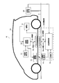
- FIG. 1 is a block diagram showing a configuration of a charging system according to Embodiment 1 of the present invention.
- the charging system 10 includes a power feeding device 100, a vehicle 150, and a power feeding side operation unit 160.
- FIG. 1 shows a power supply state in which the power supply coil 104a and the power reception coil 154a face each other.
- the power feeding device 100 is installed or embedded on the ground such that the power feeding unit 104 is exposed from the ground surface g.
- the power supply device 100 is provided in a parking space, for example, and supplies power to the power receiving unit 154 by facing the power receiving unit 154 while the vehicle 150 is parked.
- power feeding means that power is supplied from the power feeding coil 104a to the power receiving coil 154a.
- the power supply includes a preliminary power supply for supplying a small amount of power to the power receiving unit 154 and a main power supply for supplying a large amount of power to supply power to the storage battery 152 before supplying the power to the storage battery 152.
- power supply includes both standby power supply and main power supply.
- the vehicle 150 is, for example, an automobile that travels with the electric power of the storage battery 152 such as HEV (Hybrid Electric Vehicle), PEV (Plug-in Electric Vehicle), or EV (Electric Vehicle). Details of the configuration of the vehicle 150 will be described later.
- HEV Hybrid Electric Vehicle
- PEV Plug-in Electric Vehicle
- EV Electric Vehicle
- the power supply side operation unit 160 outputs a power supply start signal indicating the start of power supply or a power supply stop signal indicating the stop of power supply to the power supply apparatus 100 by an external operation.
- the vehicle 150 mainly includes a vehicle side operation unit 151, a storage battery 152, a vehicle side control unit 153, a power reception unit 154, and a vehicle side communication unit 155.
- the vehicle side operation unit 151 accepts various operations by the driver and outputs a signal corresponding to the accepted operation to the vehicle side control unit 153.
- the storage battery 152 stores electric power supplied from the power supply apparatus 100 via the power receiving unit 154.
- the vehicle-side control unit 153 Based on the various signals input from the vehicle-side operation unit 151, the vehicle-side control unit 153 performs various processes associated with power supply or various processes associated with power supply stop on the power receiving unit 154 and the vehicle-side communication unit 155. To control.
- the vehicle side control unit 153 detects the received power received by the power receiving coil 154a, and outputs the detection result of the received power to the vehicle side communication unit 155 as received power information.
- the received power information may be a value obtained by calculating the power supplied to the storage battery 152.
- the vehicle-side control unit 153 calculates the ratio of stored power with respect to full charge in the storage battery 152, and outputs the calculated ratio of stored power to the vehicle-side communication unit 155 as stored power information.
- the ratio of the stored power is calculated by the ECU, for example.
- the power receiving unit 154 includes a power receiving coil 154a.
- the power receiving coil 154 a is fed from the power feeding coil 104 a of the power feeding unit 104.
- the power receiving unit 154 supplies the power received by the power receiving coil 154 a to the storage battery 152 according to the control of the vehicle side control unit 153.
- the power receiving unit 154 is provided on the bottom, side, and top surface of the vehicle 150 so as to be exposed to the outside or covered with a resin casing.
- the vehicle side communication unit 155 transmits the received power information input from the vehicle side control unit 153 to the power supply side communication unit 101.
- the vehicle-side communication unit 155 generates a power-receivable signal indicating a power-receivable state or a power-receivable signal indicating that power-receivable is not possible according to the control of the vehicle-side control unit 153, and the generated power-receivable signal or A power reception impossible signal is transmitted to the power supply side communication unit 101.
- the vehicle side communication unit 155 transmits the stored power information input from the vehicle side control unit 153 to the power supply side communication unit 101.
- the stored power information is, for example, CAN (Controller Area Network). ) Sent using communication.
- the power reception enable signal is transmitted when the storage battery 152 needs to be charged, or when the vehicle side is capable of receiving power without detecting leakage or the like.
- the power reception impossibility signal is transmitted when the storage battery 152 is in a fully charged state and power reception is not necessary, or when the vehicle side is incapable of receiving power due to detection of electric leakage or the like.
- the power supply apparatus 100 mainly includes a power supply side communication unit 101, a storage unit 102, a power supply side control unit 103, and a power supply unit 104.
- the power supply side communication unit 101 receives the received power information from the vehicle side communication unit 155 and outputs the received power reception information to the power supply side control unit 103.
- the power supply side communication unit 101 is a vehicle side communication unit 155. Stored power information is received, and the received stored power information is output to the power supply side control unit 103.
- the power supply side communication unit 101 receives the power reception enabled signal or the power reception disabled signal from the vehicle side communication unit 155.
- the power supply side communication unit 101 outputs the received power reception enable signal or power reception disabled signal to the power supply side control unit 103.
- the storage unit 102 stores in advance a correction table in which a ratio of stored power with respect to the full charge of the storage battery 152 and a correction coefficient are associated with each other.
- the storage unit 102 stores the power supply efficiency for each frequency input from the power supply side control unit 103. A method for calculating the power supply efficiency will be described later.
- the storage unit 102 stores drive frequency information of a drive frequency start value, end value, and step value in advance. The correction table will be described later.
- the power feeding side control unit 103 receives power while sequentially changing the frequency with respect to the power feeding coil 104a when a power feeding start signal is input from the power feeding side operation unit 160 and a power receiving enable signal is input from the power feeding side communication unit 101.
- the power supply unit 104 is controlled to perform preliminary power supply to the coil 154a.
- the power supply side control unit 103 refers to the correction table stored in the storage unit 102 and reads a correction coefficient associated with the stored power ratio indicated by the stored power information input from the power supply side communication unit 101. .
- the power supply side control unit 103 calculates a frequency difference between two peaks of the power supply efficiency in the obtained frequency characteristic of the power supply efficiency, and corrects the calculated frequency difference using a correction coefficient.
- the power supply side control unit 103 determines that the main power supply is started when the corrected frequency difference is equal to or greater than the threshold value. On the other hand, when the corrected frequency difference is less than the threshold, the power supply side control unit 103 determines that the main power supply is not started. That is, the power supply side control unit 103 determines whether or not to perform the main power supply by using the fact that the frequency difference between the peaks of the power supply efficiency increases as the positional deviation between the power supply coil 104a and the power reception coil 154a decreases. . Note that the relationship between the degree of positional deviation between the power feeding coil 104a and the power receiving coil 154a and the frequency difference between the peaks of the power feeding efficiency will be described later.
- the power supply side control unit 103 controls the power supply unit 104 to start the main power supply. In addition, when it is determined that the main power supply is not started, the power supply side control unit 103 controls the power supply unit 104 not to start the main power supply.
- the power supply side control unit 103 does not start power supply or does not supply power when a power supply stop signal is input from the power supply side operation unit 160 or when a power reception disable signal is input from the power supply side communication unit 101 during power supply.
- the power supply unit 104 is controlled to stop the operation. Details of the configuration of the power supply side control unit 103 will be described later.
- the power feeding unit 104 has a power feeding coil 104a.
- the power feeding unit 104 performs preliminary power feeding from the power feeding coil 104a while sequentially changing the frequency according to the control of the power feeding side control unit 103, and also performs main power feeding.
- the power feeding unit 104 feeds power from the power feeding coil 104a to the power receiving coil 154a by, for example, an electromagnetic induction method or a magnetic resonance method.
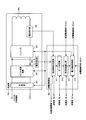
- FIG. 2 is a block diagram illustrating configurations of the power feeding unit and the power feeding side control unit according to Embodiment 1 of the present invention.
- the power supply unit 104 mainly includes a switching unit 201, an AC / DC converter 202, an inverter 203, a voltage detection unit 204, a current detection unit 205, and a power supply coil 104a.
- the switching unit 201 opens and closes the connection between the external power source (external AC power source) and the AC / DC converter 202 according to the control of the power supply control unit 214.
- the AC / DC converter 202 converts AC electrical energy supplied from an external power source into DC electrical energy and supplies it to the inverter 203.
- the output voltage of the AC / DC converter 202 may be fixed to a predetermined voltage that is determined in advance, or may be variable under the control of the power supply control unit 214.
- the inverter 203 converts the DC power supplied from the AC / DC converter 202 into AC power and supplies it to the feeding coil 104a.
- the inverter 203 can change the frequency of the output power and the magnitude of the output power under the control of the power supply control unit 214. For example, the inverter 203 is controlled to output a small amount of electric power during preliminary power supply, and is controlled to output a large amount of electric power during main power supply.
- the voltage detection unit 204 measures the voltage value of the DC power supplied from the AC / DC converter 202 to the inverter 203 and outputs the voltage value measurement result to the frequency characteristic acquisition unit 211 of the power supply side control unit 103.
- the current detection unit 205 measures the current value of the AC power supplied from the inverter 203 to the power supply coil 104a, and the measurement result of the current value is supplied to the power supply side control unit 103 (specifically, the frequency characteristic acquisition unit 211 shown in FIG. 2). Output to.
- the power supply coil 104a receives AC power from the inverter 203 to perform preliminary power supply while sequentially changing the frequency with respect to the power reception coil 154a. Supply power.
- the voltage detection part 204 was provided between the AC / DC converter 202 and the inverter 203, you may provide the voltage detection part 204 between the inverter 203 and the electric power feeding coil 104a.
- the current detection unit 205 is provided between the inverter 203 and the power supply coil 104 a, but the current detection unit is provided between the AC / DC conversion device 202 and the inverter 203 or in the input path to the AC / DC conversion device 202. 205 may be provided.
- the power feeding side control unit 103 mainly includes a frequency characteristic acquisition unit 211, a peak determination unit (corresponding to a resonance frequency specifying unit) 212, a frequency difference calculation unit 213, and a power supply control unit 214.
- the frequency characteristic acquisition unit 211 sequentially supplies the power supplied when the power supply coil 104a performs preliminary power supply based on the measurement result of the voltage value input from the voltage detection unit 204 and the measurement result of the current value input from the current detection unit 205. calculate.
- the frequency characteristic acquisition unit 211 sequentially calculates the power supply efficiency based on the calculated power supply and the received power information input from the power supply side communication unit 101.
- the frequency characteristic acquisition unit 211 sequentially stores the calculated power supply efficiency in the storage unit 102 and sequentially outputs it to the peak determination unit 212.
- the frequency characteristic acquisition method will be described later.
- the peak determination unit 212 searches for a portion where the frequency characteristic is maximum based on the frequency characteristic acquired by the frequency characteristic acquisition unit 211, and specifies the frequency where the frequency characteristic is maximum as the resonance frequency.
- the number of peaks (maximum value) is plural, and when there is no power receiving coil 154a, the number of peaks is 1. Become one.
- the peak (maximum value) when the resonance frequency is one and has a single peak is a minimum in the frequency characteristics having two resonance frequencies and bimodality. Matches.
- the peak frequency at the single peak is referred to as “natural resonance frequency of the feeding coil 104 a”, and is a trough (minimum value) frequency between the resonance frequencies of the two peaks.
- the peak determination unit 212 outputs the determination result of the peak determination process to the frequency difference calculation unit 213. The peak determination method will be described later.
- the frequency difference calculation unit 213 calculates a frequency difference between peaks from the determination result of the peak determination process input from the peak determination unit 212.
- the frequency difference calculation unit 213 refers to the correction table stored in the storage unit 102 and reads the correction coefficient associated with the ratio of the stored power indicated by the stored power information input from the power supply side communication unit 101. .
- the frequency difference calculation unit 213 corrects the calculated frequency difference using the read correction coefficient and outputs the corrected frequency difference to the power supply control unit 214.
- the power supply control unit 214 stores in the storage unit 102 in order to start standby power supply when a power supply start signal is input from the power supply side operation unit 160 and a power reception enable signal is input from the power supply side communication unit 101. Read the drive frequency information.
- the power supply control unit 214 closes the switching unit 201 to connect the external power source and the AC / DC conversion device 202, and changes the frequency of the AC power supplied to the power feeding coil 104a based on the drive frequency information.
- the inverter 203 is controlled so that As a result, the power supply unit 104 starts preliminary power supply.
- the power supply control unit 214 determines whether to perform the main power supply based on the corrected frequency difference calculation result input from the frequency difference calculation unit 213.
- the power supply control unit 214 determines that the power supply is to be performed, the power supply control unit 214 maintains the connection state between the external power source and the AC / DC conversion device 202 while keeping the switching unit 201 closed. In addition, the power supply control unit 214 controls the AC / DC conversion device 202 and the inverter 203 so as to output a larger amount of power than in the standby power supply. As a result, the power supply unit 104 performs the main power supply with higher power than the standby power supply.
- the power supply control unit 214 determines that the main power supply is not to be performed, the power supply control unit 214 controls the AC / DC converter 202 so that the external power supply and the AC / DC converter 202 are disconnected. As a result, the supply of power from the external power source to the power supply coil 104a via the AC / DC converter 202 and the inverter 203 is stopped. In this case, the power supply apparatus 100 does not perform the main power supply.
- the power supply control unit 214 stops the power supply when a power supply stop signal is input from the power supply side operation unit 160 or a power reception disable signal is input from the power supply side communication unit.
- the AC / DC converter 202 and the inverter 203 are controlled.
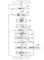
- FIG. 3 is a flowchart showing the operation of the power feeding apparatus according to Embodiment 1 of the present invention.
- the power supply control unit 214 of the power supply side control unit 103 determines whether or not there is a request for the main power supply by receiving the power supply start signal and the power reception enable signal (step ST301).
- the power supply control unit 214 repeats the process of step ST301 when there is no request for the main power supply (step ST301: NO).
- the power supply control unit 214 activates the AC / DC converter 202 and the inverter 203, and the power receiving coil 154a has the power receiving coil 154a. Whether or not (step ST302). For example, the power supply control unit 214 acquires an image captured by a camera (not shown) mounted on the vehicle 150 from the power supply side communication unit 101 via the vehicle side communication unit 155, and analyzes the acquired image. It is determined whether or not the power receiving coil 154a is on the power feeding coil 104a.
- the power supply control unit 214 controls the AC / DC converter 202 and the inverter 203 so as not to start the main power supply.
- step ST302 when power supply control section 214 determines that power receiving coil 154a is present on power supply coil 104a (step ST302: YES), AC / DC converter 202 and inverter 203 are activated.
- the frequency characteristic acquisition part 211 performs the frequency characteristic acquisition process of electric power feeding efficiency (step ST303).
- the frequency characteristic acquisition method will be described later.
- the peak determination unit 212 performs a peak determination process based on the power supply efficiency calculated before the previous time stored in the storage unit 102 and the current power supply efficiency acquired from the frequency characteristic acquisition unit 211 (step) ST304). The peak determination method will be described later.
- the peak determination unit 212 determines whether or not there is a bimodal characteristic in which two peaks of the power supply efficiency appear in the frequency characteristic of the power supply efficiency (step ST305).
- step ST305 NO
- the power supply control unit 214 determines that this power supply start is “impossible” (step ST306) and ends the process.
- the power receiving coil 154a does not exist at a position facing the power feeding coil 104a.
- the power supply apparatus 100 does not start the main power supply.
- the frequency difference calculation unit 213 calculates the frequency difference ⁇ F between the peaks of the frequency characteristics of the power supply efficiency (step ST307). .
- the frequency difference calculator 213 multiplies the frequency difference ⁇ F between peaks by the correction coefficient k read from the correction table to correct the frequency difference ⁇ F between peaks (step ST308).
- the power supply control unit 214 determines whether or not the frequency difference (k * ⁇ F) between the corrected peaks is equal to or greater than a threshold value (predetermined frequency Fd) (step ST309).
- step ST309 NO
- main power supply is “not possible”
- step ST306 main power supply is “not possible”
- the process is terminated. In this case, a positional deviation occurs between the power feeding coil 104a and the power receiving coil 154a, and the power feeding efficiency is below the allowable value or the unnecessary radiation noise is above the allowable value. As a result, the power supply apparatus 100 does not start the main power supply.
- step ST309: YES when it is determined that the frequency difference (k * ⁇ F) between the corrected peaks is equal to or greater than the threshold (step ST309: YES), the power supply control unit 214 determines that the main power supply start is “permitted” (step ST309: YES) Step ST310), the power supply control process is started (step ST311).
- the power supply apparatus 100 ends the power supply control process when the storage battery 152 is fully charged.
- step ST303 after the frequency characteristic acquisition process of step ST303 is completed, the peak determination process of step ST304 is performed. However, the frequency characteristic acquisition process of step ST303 and the peak determination process of step ST304 are performed in parallel. May be.
- FIG. 4 is a flowchart showing the frequency characteristic acquisition method according to Embodiment 1 of the present invention.
- the power supply control unit 214 acquires and sets the start value Fa, the end value Fb, and the step value Fs of the drive frequency F that is the drive frequency information stored in the storage unit 102 (step ST401).
- the power supply control unit 214 sets the start value Fa as the drive frequency F (step ST402).
- the power supply control unit 214 activates the AC / DC conversion device 202 and the inverter 203 (step ST403).
- the frequency characteristic acquisition unit 211 calculates the power supply Ws for standby power supply from the measurement result of the voltage value input from the voltage detection unit 204 and the measurement result of the current value input from the current detection unit 205 ( Step ST404).
- the feed power Ws is the power in the reserve power feed, it is lower than the feed power in the main feed.
- the frequency characteristic acquisition unit 211 acquires the received power information of the received power Wj from the power supply side communication unit 101 (step ST405).
- the frequency characteristic acquisition unit 211 calculates the power supply efficiency Dk based on the calculated power supply power Ws and the power reception power Wj acquired in step ST405 (step ST406). For example, the frequency characteristic acquisition unit 211 calculates the power supply efficiency Dk by dividing the received power Wj by the power supply power Ws (Wj / Ws).
- the frequency characteristic acquisition unit 211 stores the calculated power supply efficiency Dk in the storage unit 102.
- the power supply control unit 214 adds the step value Fs to the drive frequency F (step ST407).
- power supply control section 214 determines whether or not drive frequency F is equal to or higher than end value Fb (step ST408).
- step ST408 NO
- the power supply control unit 214 returns to the process of step ST404.
- step ST408 when drive frequency F is equal to or higher than end value Fb (step ST408: YES), power supply control unit 214 stops AC / DC converter 202 and inverter 203 (step ST409).
- the end value Fb is set to a higher frequency side than the start value Fa, so that the step value Fs is added to the drive frequency F in step ST407. However, the end value Fb is lower than the start value Fa. By setting to the side, the step value Fs may be subtracted from the drive frequency F in step ST407. Further, the drive frequency F may be increased or decreased.
- FIG. 5 is a flowchart showing the peak determination method in Embodiment 1 of the present invention.
- the peak determination process is performed using the frequency characteristic of the power supply efficiency acquired by the frequency characteristic acquisition method described above.
- the peak determination unit 212 starts a search (step ST501), and reads the power supply efficiency Dk calculated before the previous time stored in the storage unit 102 (step ST502).
- peak determination section 212 determines whether or not a peak has been detected (step ST503). For example, when the power supply efficiency calculated last time is higher than the power supply efficiency calculated last time and the power supply efficiency calculated this time is lower than the power supply efficiency calculated last time, the peak determination unit 212 has the peak power supply efficiency calculated last time. Judge that it is.
- step ST503 If it is determined that a peak has been detected (step ST503: YES), the peak determination unit 212 adds “1” as the number of peaks and causes the storage unit 102 to store the frequency Fp at which the power supply efficiency reaches a peak (step ST504).
- step ST503 when it is determined that the peak is not detected (step ST503: NO), the peak determination unit 212 skips the process of step ST504 and ends the search (step ST505).
- the search in steps ST501 to ST505 is performed in the same range as the frequency range when acquiring the frequency characteristics or in a narrower range.
- FIG. 6 is a diagram showing frequency characteristics in the first embodiment of the present invention.
- FIG. 6A shows the frequency characteristics of the power supply efficiency when the power receiving coil 154a is present at a position facing the power supply coil 104a.
- FIG. 6B shows frequency characteristics of power supply efficiency when the power supply coil 104a and the power reception coil 154a are shifted in the horizontal direction.
- the frequency difference between the peaks increases as the positional deviation between the power feeding coil 104a and the power receiving coil 154a decreases.
- the power supply apparatus 100 determines whether or not the power receiving coil 154a exists at a position facing the power supply coil 104a due to the frequency difference N1, N2 (N1> N2) between the power supply efficiency peaks in the frequency characteristics of the power supply efficiency. Can be estimated. Specifically, the power supply control unit 214 determines that the main power supply is performed when the frequency difference N1 between the peaks is equal to or greater than the threshold T (when N1 ⁇ T), and the frequency difference N2 between the peaks is less than the threshold T. In the case of (N2 ⁇ threshold T), it is determined that the main power supply is not performed.
- the frequency characteristic of the power feeding efficiency has only one peak when the power receiving coil 154a is not on the power feeding coil 104a.
- the frequency characteristics of the power supply efficiency always have two or more peaks when the power supply coil 104a and the power reception coil 154a are slightly opposed to each other.
- Fig.7 (a) shows the modification of a receiving coil.
- the power receiving coil 1541 on the power receiving side shown in FIG. 7A is configured by connecting a plurality of power receiving coils 154b and rectifiers in an array.
- the frequency characteristic line of the current value flowing through the feeding coil 104a is not the two peaks (bimodal) shown in FIG. As shown in (b), there are three or more mountains.
- the frequency difference calculation unit 213 calculates a frequency difference between any two of ⁇ f1, ⁇ f2, and ⁇ f3. Like that.
- any one of the frequency difference ⁇ f1 between the resonance frequencies f71 and f73, the frequency difference ⁇ f2 between the resonance frequencies f73 and f72, and the frequency difference ⁇ f3 between the resonance frequencies f71 and f72 is calculated.
- the frequency difference calculation unit 213 multiplies the frequency difference between the peaks by the correction coefficient k read from the correction table to correct the frequency difference between the peaks.
- the power supply control unit 214 sets the threshold value of each frequency difference when the feeding coil 104a and the receiving coil 154a are shifted, which is stored in the storage unit 102 corresponding to each frequency difference ⁇ f1, ⁇ f2, ⁇ f3. read out.
- the power supply control unit 214 compares these thresholds with the subsequent frequency differences ⁇ f1, ⁇ f2, and ⁇ f3 to determine whether or not to start the main power supply.
- FIG. 8 is a diagram showing a correction table according to the first embodiment of the present invention.
- a correction coefficient corresponding to the state of charge (SOC) of the storage battery 152 is set.
- SOC state of charge
- FIG. 2 a correction coefficient is set to reduce the frequency difference between peaks as the ratio of the stored power to the full charge of the storage battery 152 increases.
- ⁇ Modification using frequency characteristic of current value or voltage value instead of frequency characteristic of power supply efficiency> it is determined whether or not the main power supply is performed based on the frequency characteristic of the power supply efficiency at the time of the preliminary power supply, but based on the frequency characteristic of the current value or the voltage value of the power supply coil 104a at the time of the preliminary power supply. It may be determined whether or not the main power is supplied.
- the coupling coefficient changes due to the distance between the power feeding coil 104a and the power receiving coil 154a and the influence of the axis deviation. If the current value of the power supply efficiency ⁇ and the power supply coil 104a and I 1, respectively, as a function of a driving frequency f and the coupling coefficient k (1) can be expressed as equation.
- V power supply voltage ⁇ : constant
- the power supply efficiency ⁇ and current value I 1 of the feeding coil 104a respectively uniquely determined with respect to the driving frequency f.
- the current value I 1 of the feeding coil 104a shows a characteristic having two resonance frequencies f 3, f 4 (maximum point) ((2) below reference expression). That is, feeding the current value I 1 efficiency ⁇ correlates.
- FIG. 9 shows the relationship between the power supply efficiency with respect to the frequency and the power supply side coil current (current flowing through the power supply coil 104a).
- the current value I 1 flowing through the power feeding coil 104 a has a correlation with the input current value of the AC / DC converter 202 or the output current value of the AC / DC converter 202. That is, the current value I 1 flowing through the power feeding coil 104 a can be estimated from the input current value of the AC / DC converter 202 or the output current value of the AC / DC converter 202.
- the current value measured between the switching unit 201 and the AC / DC converter 202 or between the AC / DC converter 202 and the inverter 203 is used without directly detecting the current of the power feeding coil 104a.
- the frequency characteristic of the power supply efficiency can be obtained.
- the frequency characteristic of the power supply efficiency is calculated, so that it is not necessary to perform wireless communication with the vehicle 150, and processing on the power supply apparatus 100 side is performed.
- the frequency characteristic of the power feeding efficiency can be obtained only with the above.
- unnecessary radiation noise can be reduced by performing the main power supply in a state where the power feeding coil and the power receiving coil face each other.
- unnecessary radiation noise it is possible to obtain effects such as preventing adverse effects on the human body and preventing interference with peripheral devices.
- the frequency difference between the peaks is corrected according to the ratio of the stored power with respect to the full charge of the storage battery 152, so that it is possible to correctly determine whether or not to supply power according to the ratio of the stored power. .
- the power receiving coil 154a is not on the power supply coil 104a, the main power supply is not performed, so that the power supply apparatus 100 can be prevented from performing the main power supply in a no-load state. An adverse effect on the human body can be prevented.
- the standby power supply is performed with power lower than the power supply power of the main power supply, so that power consumption in the power supply apparatus 100 can be suppressed.
- the frequency difference between the peaks is corrected using the correction coefficient.
- the frequency difference between the peaks may be compared with a threshold value without being corrected.
- the power receiving coil 154a may be supplied with power when the frequency difference between the natural resonance frequency of the power supply coil 104a and any one of the resonance frequencies is equal to or greater than a threshold value.
- the natural resonance frequency of the power feeding coil 104a is the resonance frequency of the power feeding coil 104a in a state where the power receiving coil 154a is not present. Since the natural resonance frequency of the feeding coil 104a is a frequency of a valley (minimum value) between the resonance frequencies, the difference between the “resonance frequency of the feeding coil 104a” and one of the two resonance frequencies is compared with a threshold value. You may do it. As a result, the determination can be performed earlier than the threshold determination of the difference between the two resonance frequencies.
- the correction table in which the stored power for the full charge of the storage battery 152 is associated with the correction coefficient is used, but the parameters other than the stored power for the full charge of the storage battery 152 are associated with the correction coefficient.
- a correction table may be used.
- the power supply side control unit 103 determines whether or not the main power supply is performed when a power supply start signal is input from the power supply side operation unit 160.
- the vehicle side communication unit 155 When the power supply start signal is acquired from the power supply side communication unit 101, it may be determined whether or not the main power supply is performed. That is, the power supply side control unit 103 may determine whether or not the main power supply is performed when a power supply start signal is acquired from the vehicle 150 by any means.
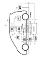
- FIG. 10 is a block diagram showing the configuration of the charging system according to Embodiment 2 of the present invention.
- the charging system 10A is configured to determine whether or not a power feeding operation is possible on the power receiving side (vehicle 150 side).
- the charging system 10A includes a power feeding device 100A, a vehicle 150A, and a power feeding side operation unit 160.
- a power feeding device 100A for supplying power to a power feeding device 100A
- a vehicle 150A for supplying power to a power feeding device.
- a power feeding side operation unit 160 for supplying power to a power feeding device.
- FIG. 10 shows a power supply state in which the power supply coil 104a and the power reception coil 154a face each other.
- the power feeding apparatus 100 ⁇ / b> A has the same basic configuration as the power feeding apparatus 100.
- power supply apparatus 100A power supply unit 104 is installed or embedded on the ground so as to be exposed from ground surface g.
- permission / non-permission of power supply from the power supply coil 104a to the power reception coil 154a is performed based on the frequency difference between the specified resonance frequencies by specifying the resonance frequency based on the frequency characteristics of the power supply efficiency.
- determination regarding power feeding based on the frequency difference between the specified resonance frequencies is performed on the power receiving side (vehicle 150A side).
- the vehicle 150A is, for example, an automobile that runs on the electric power of the storage battery 152, such as HEV (Hybrid Electric Vehicle), PEV (Plug-in Electric Vehicle), or EV (Electric Vehicle). Note that the configuration of the vehicle 150A newly includes a vehicle-side storage unit 156 as compared with the configuration of the vehicle 150 shown in FIG. Details will be described later.
- HEV Hybrid Electric Vehicle
- PEV Plug-in Electric Vehicle
- EV Electric Vehicle
- the power supply side operation unit 160 outputs a power supply start signal indicating the start of power supply or a power supply stop signal indicating the stop of power supply to the power supply apparatus 100A by an external operation.
- the basic configuration of the power feeding apparatus 100A is the same as that of the power feeding apparatus 100.
- the power feeding apparatus 100A mainly includes a power feeding side communication unit 101A, a storage unit 102, a power feeding side control unit 103A, and a power feeding unit 104.
- the power supply side communication unit 101 ⁇ / b> A receives the received power information from the vehicle side communication unit 155, and outputs the received power reception information to the power supply side control unit 103.
- the power supply side communication unit 101A receives the stored power information from the vehicle side communication unit 155, and outputs the received stored power information to the power supply side control unit 103A.
- the power supply side communication unit 101A receives the power reception enable signal or the power reception impossible signal from the vehicle side communication unit 155.
- the power supply side communication unit 101A outputs the received power reception enable signal or power reception disabled signal to the power supply side control unit 103A.
- the power supply side communication unit 101A transmits to the vehicle side communication unit 155 the power supplied when the power supply coil 104a is supplied (mainly spare power supply) and the frequency at that time.
- the storage unit 102 stores in advance a correction table that associates the ratio of the stored power with respect to the full charge of the storage battery 152 and the correction coefficient.
- the storage unit 102 stores the power supply efficiency for each frequency transmitted from the vehicle side communication unit 155.
- the power feeding side control unit 103A receives power while sequentially changing the frequency with respect to the power feeding coil 104a when a power feeding start signal is input from the power feeding side operation unit 160 and a power receiving enable signal is input from the power feeding side communication unit 101A.
- the power supply unit 104 is controlled to perform preliminary power supply to the coil 154a.
- the power supply side control unit 103 ⁇ / b> A controls the power supply unit 104 to start the main power supply when a power reception enable signal is input from the vehicle side communication unit 155 via the power supply communication unit 101 ⁇ / b> A.
- the power feeding side control unit 103A does not start power feeding when a power feeding stop signal is input from the power feeding side operation unit 160 or when a power reception impossible signal is input from the power feeding side communication unit 101A.
- the power feeding unit 104 is controlled to stop power feeding.
- the power feeding unit 104 has a power feeding coil 104a.
- the power feeding unit 104 performs preliminary power feeding from the power feeding coil 104a while sequentially changing the frequency in accordance with the control of the power feeding side control unit 103A, and also performs main power feeding.
- the power feeding unit 104 feeds power from the power feeding coil 104a to the power receiving coil 154a by, for example, an electromagnetic induction method or a magnetic resonance method.
- the vehicle 150A includes a power receiving device 1000.
- the power receiving device 1000 includes a vehicle side operation unit 151, a storage battery 152, a vehicle side control unit 153A, a power reception unit 154, a vehicle side communication unit 155, and a vehicle side storage unit. 156 and the like.
- the vehicle side operation unit 151 receives various operations by the driver and outputs a signal corresponding to the received operation to the vehicle side control unit 153A.
- the storage battery 152 stores electric power supplied from the power supply apparatus 100A via the power receiving unit 154.
- the vehicle-side control unit 153A Based on the various signals input from the vehicle-side operation unit 151, the vehicle-side control unit 153A performs various processes associated with power supply or various processes associated with power supply stop on the power receiving unit 154 and the vehicle-side communication unit 155. To control.
- the vehicle-side control unit 153A detects the received power received by the power receiving coil 154a, and outputs the received power detection result to the vehicle-side storage unit 156 and the vehicle-side communication unit 155 as received power information.
- the vehicle-side control unit 153A calculates the ratio of stored power with respect to full charge in the storage battery 152, and outputs the calculated ratio of stored power to the vehicle-side communication unit 155 as stored power information.
- the ratio of the stored power is calculated by the ECU, for example.
- the power receiving unit 154 includes a power receiving coil 154a.
- the power receiving coil 154 a is fed from the power feeding coil 104 a of the power feeding unit 104.
- the power receiving unit 154 supplies the power received by the power receiving coil 154a to the storage battery 152 according to the control of the vehicle side control unit 153A.
- the power receiving unit 154 is provided in a state of being exposed to the outside or covered with a resin casing at the bottom, side, and top surface of the vehicle 150A.
- the vehicle-side communication unit 155 transmits to the vehicle-side control unit 153A the power supply power received from the power supply-side communication unit 101A when supplying power (mainly backup power supply) to the power supply coil 104a and the frequency at that time. Further, the vehicle side communication unit 155 transmits the received power information input from the vehicle side control unit 153A to the power supply side communication unit 101A. The vehicle-side communication unit 155 generates a power-receivable signal indicating a power-receivable state or a power-receivable signal indicating that power-reception is not possible according to the control of the vehicle-side control unit 153A. A power reception impossible signal is transmitted to the power supply side communication unit 101.
- the vehicle-side communication unit 155 transmits the stored power information input from the vehicle-side control unit 153A to the power supply-side communication unit 101A.
- the stored power information is transmitted using, for example, CAN (Controller Area Network) communication.
- the power-receivable signal is the storage battery 1 This is transmitted when 52 is in a state where charging is required, or when leakage or the like is not detected and the vehicle can receive power.
- the power reception impossibility signal is transmitted when the storage battery 152 is in a fully charged state and power reception is not necessary, or when the vehicle side is incapable of receiving power due to detection of electric leakage or the like.
- the vehicle-side storage unit 156 stores the received power of the power reception unit 154 acquired by the vehicle-side control unit 153A. Further, the power supply efficiency for each frequency calculated by the frequency characteristic acquisition unit 1531 (see FIG. 11) and the frequency characteristic based on the power supply efficiency are stored.
- the vehicle-side storage unit 156 may store in advance the correction table stored in the storage unit 102 of the first embodiment. This correction table is configured by associating the ratio of the stored power with respect to the full charge of the storage battery 152 and the correction coefficient (see FIG. 8).
- the vehicle-side storage unit 156 stores in advance drive frequency information of a drive frequency start value, end value, and step value.
- FIG. 11 is a diagram showing an example of the configuration of the power receiving device 1000 of the vehicle 150A according to Embodiment 2 of the present invention.
- the vehicle-side control unit 153A mainly includes a frequency characteristic acquisition unit 1531, a peak determination unit (resonance frequency specifying unit) 1532, a frequency difference calculation unit 1533, and a power supply permission determination unit 1534. It is configured.
- the functions of the frequency characteristic acquisition unit 1531, the peak determination unit (resonance frequency specifying unit) 1532, and the frequency difference calculation unit 1533 have the same names in the power supply side control unit 103 in the first embodiment. This is the same as the function of the component.
- the frequency characteristic acquisition unit 1531 receives the supplied power and the frequency at that time from the power supply side via the vehicle side communication unit 155.
- the frequency characteristic acquisition unit 1531 calculates the feeding efficiency from the feeding power and frequency received from the feeding side and the received power of the power receiving unit 154.
- the frequency characteristic acquisition unit 1531 calculates a frequency characteristic based on the calculated power supply efficiency for each frequency, sequentially stores the frequency characteristic in the vehicle-side storage unit 156, and sequentially outputs it to the peak determination unit 1532.
- the peak determination unit 1532 searches for a portion where the frequency characteristic is maximum based on the frequency characteristic acquired by the frequency characteristic acquisition unit 1531 and identifies the frequency where the frequency characteristic is maximum as the resonance frequency. Specifically, the peak determination unit 1532 is based on a comparison result between the power supply efficiency calculated before the previous time stored in the vehicle-side storage unit 156 and the current power supply efficiency input from the frequency characteristic acquisition unit 1531. Then, a peak determination process for power supply efficiency is performed. In this peak determination process, the peak determination unit 1532 searches for the maximum frequency in the frequency characteristic of the power supply efficiency and specifies it as the resonance frequency. Since this peak determination method is the same as that by the peak determination unit 212 on the power feeding side described above, the description will be made in detail. The peak determination unit 1532 outputs the determination result of the peak determination process to the frequency difference calculation unit 1533.
- the frequency difference calculation unit 1533 calculates the frequency difference between peaks from the determination result of the peak determination process input from the peak determination unit 1532. Since this frequency difference calculation method is the same as that performed by the power supply side frequency difference calculation unit 213, description thereof is omitted.
- the frequency difference calculation unit 1533 refers to a correction table similar to the correction table stored in the storage unit 102 if it is stored in the vehicle-side storage unit 156. That is, the frequency difference calculation unit 1533 corrects the calculated frequency difference using the correction coefficient read from the vehicle-side storage unit 156 and outputs the corrected frequency difference to the power supply permission determination unit 1534. As described above, the frequency difference calculation unit 1533 may correct the frequency difference according to the remaining capacity of the storage battery 152.
- the power supply permission determination unit 1534 receives a power supply start signal from the vehicle-side operation unit 151 and, based on the frequency difference input from the frequency difference calculation unit 1533, receives a power reception enable signal (power supply permission signal) on the power supply device 100A side. And a power reception disable signal (power supply non-permission signal) to be transmitted.
- the power supply permission determination unit 1534 reads a threshold value corresponding to the deviation between the power supply coil 104a and the power reception coil 154a from the vehicle-side storage unit 156 and compares it with the input frequency difference. If the frequency difference is greater than or equal to the threshold value, a power reception enable signal is generated and transmitted to the power feeding apparatus 100A (specifically, the power feeding side communication unit 101A) via the vehicle side communication unit 155.
- the power supply permission determination unit 1534 causes the vehicle-side communication unit 155 to generate a power reception non-permission signal (power supply non-permission signal), thereby supplying the power supply device 100A. (Details are transmitted to the power supply side communication unit 101A).
- the frequency characteristic acquisition unit 1531 calculates the power supply efficiency from the power supplied from the power supply side and the frequency at that time and the power received by the power receiving unit 154.
- the peak determination unit (resonance frequency specifying unit) 1532 specifies the resonance frequency based on the calculated frequency characteristics of the power supply efficiency in the power supply coil 104a.
- the frequency difference calculation unit 1533 calculates the frequency difference between the specified resonance frequencies.
- the power supply permission determination unit 1534 determines whether power supply is not permitted to the power receiving coil 154a, and outputs the result to the vehicle side communication unit 155.
- the vehicle-side communication unit 155 generates a power reception enable signal and a power reception disable signal according to the result of the power supply permission determination unit 1534, and transmits them to the power supply device 100A.
- the power supply device 100A performs processing according to the received signal.
- whether power can be supplied from the power supply coil 104a to the power reception coil 154a can be determined based on the frequency difference between the resonance frequencies.
- power can be reliably supplied in a state where the power feeding coil 104a and the power receiving coil 154a face each other, and unnecessary radiation noise can be reduced.
- unnecessary radiation noise it is possible to obtain effects such as preventing adverse effects on the human body and preventing interference with peripheral devices.
- the power supply device is suitable for supplying electric power to a storage battery mounted on a vehicle via a power receiving unit of the vehicle.
Landscapes
- Engineering & Computer Science (AREA)
- Power Engineering (AREA)
- Computer Networks & Wireless Communication (AREA)
- Transportation (AREA)
- Mechanical Engineering (AREA)
- Charge And Discharge Circuits For Batteries Or The Like (AREA)
- Electric Propulsion And Braking For Vehicles (AREA)
- Current-Collector Devices For Electrically Propelled Vehicles (AREA)
Abstract
給電装置(100)は、車輌(150)に搭載されている蓄電池(152)に対して車輌(150)の受電部(154)を介して電力を供給する。給電部(104)は、受電部(154)に対して周波数を順次変更しながら予備給電を行うとともに予備給電よりも大電力で本給電を行う。給電側制御部(103)は、給電コイル(104a)に関連する周波数特性を取得し、所得した周波数特性に基づいて共振周波数を特定する。また、給電側制御部(103)は、共振周波数間の周波数差に基づいて受電コイル(154a)へ給電を行うか否かを判定する。
Description
本発明は、車輌に搭載されている蓄電池に対して車輌の受電部を介して電力を供給する給電装置に関する。
従来、車輌に搭載された蓄電池を地上の給電装置を用いて充電する非接触充電システムが知られている。非接触充電システムでは、無駄な電力消費を抑制するために、高い給電効率で給電することが好ましい。
従来、給電コイルと受電コイルとの距離が変化する場合において、高い給電効率を得るために、最大電力となる周波数を決定して給電する非接触充電システムが知られている(例えば、特許文献1)。特許文献1では、給電装置は、給電コイルから給電する電力の周波数を順次変更させ、受電電力が最大となる周波数を決定するとともに、決定した周波数で給電を行う。これにより、特許文献1の非接触充電システムでは、非接触電力伝送を効率よく実現することができる。
しかしながら、特許文献1においては、給電コイルと受電コイルとに位置ズレが生じた状態でも、最大電力を設定して給電を行うので、給電コイルと受電コイルとのズレ幅によっては不要輻射ノイズが大きくなるという問題がある。
本発明の目的は、給電コイルと受電コイルとが対向した状態において給電を行うことにより、不要輻射ノイズを低減することができる給電装置、受電装置及び給電方法を提供することである。
本発明に係る給電装置は、外部の受電コイルに電磁作用を用いて電力を供給する給電装置であって、電磁作用を用いて電力を給電する給電コイルと、前記給電コイルに関連する周波数特性を取得する周波数特性取得部と、前記周波数特性に基づいて複数の共振周波数を特定する共振周波数特定部と、前記複数の共振周波数の間の周波数差に基づいて前記受電コイルへ給電を行うか否かを判定する電力供給制御部と、を備えた構成を採る。
本発明に係る受電装置は、外部の給電コイルから電磁作用を用いて電力が供給される受電装置であって、前記給電コイルにより電磁作用を用いて電力が給電される受電コイルと、前記給電コイルと前記受電コイルとの間の給電効率の周波数特性を取得する周波数特性取得部と、前記周波数特性に基づいて共振周波数を特定する共振周波数特定部と、前記共振周波数間の周波数差に基づいて、前記給電コイルから前記受電コイルへの給電の許可不許可を判定する給電許可判定部と、を備えた構成を採る。
本発明に係る給電方法は、外部の受電コイルに電磁作用を用いて電力を供給する給電方法であって、電磁作用を用いて給電コイルに電力を給電する給電ステップと、給電される前記給電コイルに関連する周波数特性を取得する周波数特性取得ステップと、取得した前
記周波数特性に基づいて共振周波数を特定する共振周波数特定ステップと、前記共振周波数間の周波数差に基づいて前記受電コイルへ給電を行うか否かを判定する判定ステップと、を有するようにした。
記周波数特性に基づいて共振周波数を特定する共振周波数特定ステップと、前記共振周波数間の周波数差に基づいて前記受電コイルへ給電を行うか否かを判定する判定ステップと、を有するようにした。
本発明によれば、給電コイルと受電コイルとが対向した状態において給電を行うことにより、不要輻射ノイズを低減することができる。
以下、本発明の実施の形態について、図面を参照して詳細に説明する。
(実施の形態1)
<充電システムの構成>
本発明の実施の形態1における充電システム10の構成について、図1を用いて説明する。図1は、本発明の実施の形態1における充電システムの構成を示すブロック図である。
<充電システムの構成>
本発明の実施の形態1における充電システム10の構成について、図1を用いて説明する。図1は、本発明の実施の形態1における充電システムの構成を示すブロック図である。
充電システム10は、給電装置100と、車輌150と、給電側操作部160とを有している。
なお、図1は、給電コイル104aと受電コイル154aとが対向した給電可能な状態を示す。
給電装置100は、給電部104が地表gから露出するように地面上に設置もしくは埋設される。給電装置100は、例えば駐車スペースに設けられ、車輌150の駐車中に、受電部154に対向することにより受電部154に対して給電する。ここで、給電とは、給電コイル104aから受電コイル154aに電力を供給することを言う。給電には、蓄電池152に電力を供給する前において、受電部154に少ない電力を供給する予備給電と、蓄電池152に電力を供給するために大きな電力を供給する本給電とがある。なお、以下の説明において、単に「給電」と記載しているものについては、予備給電と本給電との両方を含むものとする。
車輌150は、例えば、HEV(Hybrid Electric Vehicle)、PEV(Plug-in Electric Vehicle)またはEV(ElectricVehicle)といった蓄電池152の電力で走行する
自動車である。なお、車輌150の構成の詳細については後述する。
自動車である。なお、車輌150の構成の詳細については後述する。
給電側操作部160は、外部からの操作により、給電の開始を示す給電開始信号または給電の停止を示す給電停止信号を給電装置100に出力する。
<車輌の構成>
本発明の実施の形態における車輌150の構成について、図1を用いて説明する。
本発明の実施の形態における車輌150の構成について、図1を用いて説明する。
車輌150は、車輌側操作部151と、蓄電池152と、車輌側制御部153と、受電部154と、車輌側通信部155とから主に構成されている。
車輌側操作部151は、ドライバーによる各種操作を受け付け、受け付けた操作に応じた信号を車輌側制御部153に出力する。
蓄電池152は、給電装置100から受電部154を介して供給される電力を蓄える。
車輌側制御部153は、車輌側操作部151から入力された各種信号に基づいて、受電部154及び車輌側通信部155に対して、給電に伴う各種処理または給電停止に伴う各種処理を行うように制御する。車輌側制御部153は、受電コイル154aで受電した受電電力を検出し、受電電力の検出結果を受電電力情報として車輌側通信部155に出力する。なお、受電電力情報は蓄電池152に供給される電力を算出した値としてもよい。車輌側制御部153は、蓄電池152における満充電に対する蓄積電力の割合を算出し、算出した蓄積電力の割合を蓄積電力情報として車輌側通信部155に出力する。蓄積電力の割合は、例えばECUにおいて算出される。
受電部154は、受電コイル154aを有している。受電コイル154aは、給電部104の給電コイル104aから給電される。受電部154は、車輌側制御部153の制御に従って、受電コイル154aで受電した電力を蓄電池152に供給する。受電部154は、車輌150の底部、側面、天面において外部に露出、もしくは樹脂筐体で覆われた状態で設けられている。
車輌側通信部155は、車輌側制御部153から入力された受電電力情報を給電側通信部101に対して送信する。車輌側通信部155は、車輌側制御部153の制御に従って、受電可能な状態を示す受電可信号または受電が不可能な状態であることを表す受電不可信号を生成し、生成した受電可信号または受電不可信号を給電側通信部101に送信する。車輌側通信部155は、車輌側制御部153から入力された蓄積電力情報を給電側通信部101に対して送信する。蓄積電力情報は、例えばCAN(Controller Area Network
)通信を用いて送信される。ここで、受電可信号は、蓄電池152が充電を必要としている状態である場合、または、漏電等が検知されず車輌側が受電を行うことが可能な状態である場合等に送信される。受電不可信号は、蓄電池152が満充電の状態で受電が不要である場合、または、漏電等が検知されて車輌側が受電を行うことが不可能な状態である場合等に送信される。
)通信を用いて送信される。ここで、受電可信号は、蓄電池152が充電を必要としている状態である場合、または、漏電等が検知されず車輌側が受電を行うことが可能な状態である場合等に送信される。受電不可信号は、蓄電池152が満充電の状態で受電が不要である場合、または、漏電等が検知されて車輌側が受電を行うことが不可能な状態である場合等に送信される。
<給電装置の構成>
本発明の実施の形態に係る給電装置100の構成について、図1を用いて説明する。
本発明の実施の形態に係る給電装置100の構成について、図1を用いて説明する。
給電装置100は、給電側通信部101と、記憶部102と、給電側制御部103と、給電部104とから主に構成されている。
給電側通信部101は、車輌側通信部155から受電電力情報を受信し、受信した受電電力情報を給電側制御部103に出力する。給電側通信部101は、車輌側通信部155
から蓄積電力情報を受信し、受信した蓄積電力情報を給電側制御部103に出力する。給電側通信部101は、車輌側通信部155からの受電可信号または受電不可信号を受信する。給電側通信部101は、受信した受電可信号または受電不可信号を給電側制御部103に出力する。
から蓄積電力情報を受信し、受信した蓄積電力情報を給電側制御部103に出力する。給電側通信部101は、車輌側通信部155からの受電可信号または受電不可信号を受信する。給電側通信部101は、受信した受電可信号または受電不可信号を給電側制御部103に出力する。
記憶部102は、蓄電池152の満充電に対する蓄積電力の割合と補正係数とを対応付けた補正テーブルを予め記憶している。記憶部102は、給電側制御部103から入力された周波数毎の給電効率を記憶する。なお、給電効率の算出方法については後述する。記憶部102は、駆動周波数の開始値、終了値及びステップ値の駆動周波数情報を予め記憶している。なお、補正テーブルについては後述する。
給電側制御部103は、給電側操作部160から給電開始信号が入力されるとともに給電側通信部101から受電可信号が入力された際に、給電コイル104aに対して周波数を順次変更させながら受電コイル154aに対して予備給電を行うように給電部104を制御する。
給電側制御部103は、記憶部102に記憶されている補正テーブルを参照して、給電側通信部101から入力された蓄積電力情報が示す蓄積電力の割合に対応付けられている補正係数を読み出す。
給電側制御部103は、求めた給電効率の周波数特性において、給電効率の2つのピーク間の周波数差を算出し、算出した周波数差を、補正係数を用いて補正する。給電側制御部103は、補正後の周波数差が閾値以上の場合には、本給電を開始するものと判定する。一方、給電側制御部103は、補正後の周波数差が閾値未満の場合には、本給電を開始しないものと判定する。即ち、給電側制御部103は、給電コイル104aと受電コイル154aとの位置ズレが小さいほど、給電効率のピーク間の周波数差が大きくなることを利用して、本給電するか否かを判定する。なお、給電コイル104aと受電コイル154aとの位置ズレの程度と、給電効率のピーク間の周波数差との関係については後述する。
給電側制御部103は、本給電を開始するものと判定した場合(例えば、図1の状態の場合)には、給電部104に対して本給電を開始するように制御する。また、給電側制御部103は、本給電を開始しないものと判定した場合には、給電部104に対して本給電を開始しないように制御する。
給電側制御部103は、給電中において、給電側操作部160より給電停止信号が入力された場合、または給電側通信部101より受電不可信号が入力された場合に、給電を開始させないかまたは給電を停止するように給電部104を制御する。なお、給電側制御部103の構成の詳細については後述する。
給電部104は、給電コイル104aを有している。給電部104は、給電側制御部103の制御に従って、周波数を順次変更しながら給電コイル104aより予備給電を行い、また、本給電を行う。給電部104は、例えば電磁誘導方式または磁気共鳴方式により、給電コイル104aから受電コイル154aに給電する。
<給電部の構成>
本発明の実施の形態における給電部104の構成について、図2を用いて説明する。図2は、本発明の実施の形態1における給電部及び給電側制御部の構成を示すブロック図である。
本発明の実施の形態における給電部104の構成について、図2を用いて説明する。図2は、本発明の実施の形態1における給電部及び給電側制御部の構成を示すブロック図である。
給電部104は、切替部201と、AC/DC変換装置202と、インバータ203と
、電圧検知部204と、電流検知部205と、給電コイル104aとから主に構成されている。
、電圧検知部204と、電流検知部205と、給電コイル104aとから主に構成されている。
切替部201は、電力供給制御部214の制御に従って、外部電源(外部交流電源)とAC/DC変換装置202との接続を開閉する。
AC/DC変換装置202は、外部電源から供給される交流の電気エネルギを直流の電気エネルギに変換してインバータ203に供給する。AC/DC変換装置202の出力電圧は、予め決められた所定電圧に固定されていてもよいし、電力供給制御部214の制御によって可変であってもよい。
インバータ203は、AC/DC変換装置202から供給される直流電力を交流電力に変換して給電コイル104aに供給する。インバータ203は、電力供給制御部214の制御によって、出力電力の周波数、および、出力電力の大きさを変更できる。インバータ203は、例えば予備給電の際には、小電力の出力を行うように制御され、本給電の際には、大電力の出力を行うように制御される。
電圧検知部204は、AC/DC変換装置202からインバータ203に供給される直流電力の電圧値を測定し、電圧値の測定結果を給電側制御部103の周波数特性取得部211に出力する。
電流検知部205は、インバータ203から給電コイル104aに供給される交流電力の電流値を測定し、電流値の測定結果を給電側制御部103(詳細には図2に示す周波数特性取得部211)に出力する。
給電コイル104aは、インバータ203より交流電力の供給を受けることにより、受電コイル154aに対して周波数を順次変更しながら予備給電を行い、また、受電コイル154aに対して予備給電よりも大電力で本給電を行う。
なお、AC/DC変換装置202とインバータ203との間に電圧検知部204を設けたが、インバータ203と給電コイル104aとの間に電圧検知部204を設けてもよい。また、インバータ203と給電コイル104aとの間に電流検知部205を設けたが、AC/DC変換装置202とインバータ203との間、または、AC/DC変換装置202への入力経路に電流検知部205を設けてもよい。
<給電側制御部の構成>
本発明の実施の形態における給電側制御部103の構成について、図2を用いて説明する。
本発明の実施の形態における給電側制御部103の構成について、図2を用いて説明する。
給電側制御部103は、周波数特性取得部211と、ピーク判定部(共振周波数特定部に相当)212と、周波数差算出部213と、電力供給制御部214とから主に構成されている。
周波数特性取得部211は、電圧検知部204から入力された電圧値の測定結果と、電流検知部205から入力された電流値の測定結果により、給電コイル104aから予備給電する際の給電電力を順次算出する。周波数特性取得部211は、算出した給電電力と給電側通信部101から入力された受電電力情報とに基づいて、給電効率を順次算出する。周波数特性取得部211は、算出した給電効率を記憶部102に順次記憶させるとともにピーク判定部212に順次出力する。なお、周波数特性取得方法については後述する。
ピーク判定部212は、周波数特性取得部211で取得した周波数特性に基づいて、周波数特性が極大となる部分を探索し、極大となる周波数を共振周波数として特定する。給電コイル104aに対向して、受電コイル154aが少なくとも一部が重なるように存在する場合には、ピーク(極大値)の数は複数になり、受電コイル154aが無い場合にはピークの数は1つになる。
なお、給電コイル104aの周波数特性において、共振周波数が一つであり単峰となっているときのピーク(極大値)は、共振周波数が二つあり双峰性を有する周波数特性において極小となる部分と一致する。単峰でのピークの周波数を「給電コイル104aの固有共振周波数」と称し、双峰となる共振周波数の間の谷(極小値)の周波数となる。ピーク判定部212は、ピーク判定処理の判定結果を周波数差算出部213に出力する。なお、ピーク判定方法については後述する。
周波数差算出部213は、ピーク判定部212から入力されたピーク判定処理の判定結果よりピーク間の周波数差を算出する。周波数差算出部213は、記憶部102に記憶されている補正テーブルを参照して、給電側通信部101から入力された蓄積電力情報が示す蓄積電力の割合に対応付けられている補正係数を読み出す。周波数差算出部213は、読み出した補正係数を用いて、算出した周波数差を補正して電力供給制御部214に出力する。
電力供給制御部214は、給電側操作部160より給電開始信号が入力されるとともに給電側通信部101より受電可信号が入力された場合に、予備給電を開始するために、記憶部102に記憶されている駆動周波数情報を読み出す。そして、電力供給制御部214は、切替部201を閉じて外部電源とAC/DC変換装置202とを接続状態にするとともに、駆動周波数情報に基づいて給電コイル104aに供給する交流電力の周波数を変更させるようにインバータ203を制御する。これにより、給電部104は、予備給電を開始する。
電力供給制御部214は、周波数差算出部213から入力された補正された周波数差の算出結果に基づいて、本給電するか否かを判定する。
電力供給制御部214は、本給電するものと判定した場合には、切替部201を閉じたままにして外部電源とAC/DC変換装置202との接続状態を維持する。また、電力供給制御部214は、予備給電の際よりも大電力を出力するようにAC/DC変換装置202及びインバータ203を制御する。これにより、給電部104は、予備給電よりも大電力で本給電を行う。
電力供給制御部214は、本給電しないものと判定した場合には、AC/DC変換装置202を制御して、外部電源とAC/DC変換装置202とを非接続状態にする。これにより、AC/DC変換装置202及びインバータ203を介した給電コイル104aに対する外部電源からの電力の供給は停止する。この場合、給電装置100は、本給電を行わない。
電力供給制御部214は、給電を開始した後、給電側操作部160より給電停止信号が入力されるか、または給電側通信部より受電不可信号が入力された場合には、給電を停止するようにAC/DC変換装置202及びインバータ203を制御する。
<給電装置の動作>
本発明の実施の形態に係る給電装置100の動作について、図3を用いて説明する。図3は、本発明の実施の形態1に係る給電装置の動作を示すフロー図である。
本発明の実施の形態に係る給電装置100の動作について、図3を用いて説明する。図3は、本発明の実施の形態1に係る給電装置の動作を示すフロー図である。
まず、給電側制御部103の電力供給制御部214は、給電開始信号が入力されるとともに受電可信号が入力されることにより本給電の要求があったか否かを判定する(ステップST301)。
電力供給制御部214は、本給電の要求がない場合(ステップST301:NO)には、ステップST301の処理を繰り返す。
一方、電力供給制御部214は、本給電の要求があった場合(ステップST301:YES)には、AC/DC変換装置202及びインバータ203を起動して、給電コイル104a上に受電コイル154aが有るか否かを判定する(ステップST302)。例えば、電力供給制御部214は、車輌150に搭載されている図示しないカメラにより撮像した画像を、車輌側通信部155を介して給電側通信部101より取得し、取得した画像を解析することにより給電コイル104a上に受電コイル154aが有るか否かを判定する。
電力供給制御部214は、給電コイル104a上に受電コイル154aが無いと判定した場合(ステップST302:NO)には、本給電を開始しないようにAC/DC変換装置202及びインバータ203を制御する。
一方、電力供給制御部214は、給電コイル104a上に受電コイル154aが有ると判定した場合(ステップST302:YES)には、AC/DC変換装置202及びインバータ203を起動させる。
そして、周波数特性取得部211は、給電効率の周波数特性取得処理を行う(ステップST303)。なお、周波数特性取得方法については後述する。
次に、ピーク判定部212は、記憶部102に記憶されている前回以前に算出した給電効率と、周波数特性取得部211より取得し今回の給電効率とに基づいて、ピーク判定処理を行う(ステップST304)。なお、ピーク判定方法については後述する。
また、ピーク判定部212は、給電効率の周波数特性において給電効率の2つのピークが現れる双峰特性があるか否かを判定する(ステップST305)。
電力供給制御部214は、ピーク判定部212において双峰特性なしと判定した場合(ステップST305:NO)には、本給電開始「不可」と判定し(ステップST306)、処理を終了する。この場合は、給電コイル104aに対向する位置に受電コイル154aが存在していない状態である。これにより、給電装置100は、本給電を開始しない。
一方、周波数差算出部213は、ピーク判定部212において双峰特性ありと判定した場合(ステップST305:YES)には、給電効率の周波数特性のピーク間の周波数差ΔFを算出する(ステップST307)。
次に、周波数差算出部213は、ピーク間の周波数差ΔFに対して、補正テーブルから読み出した補正係数kを乗算して、ピーク間の周波数差ΔFを補正する(ステップST308)。
次に、電力供給制御部214は、補正後のピーク間の周波数差(k*ΔF)が閾値(所定周波数Fd)以上であるか否かを判定する(ステップST309)。
電力供給制御部214は、補正後のピーク間の周波数差(k*ΔF)が閾値未満であると判定した場合(ステップST309:NO)には、本給電開始「不可」と判定し(ステップST306)、処理を終了する。この場合は、給電コイル104aと受電コイル154aとに位置ズレが生じており、給電効率が許容値以下または不要輻射ノイズが許容値以上の状態である。これにより、給電装置100は、本給電を開始しない。
一方、電力供給制御部214は、補正後のピーク間の周波数差(k*ΔF)が閾値以上であると判定した場合(ステップST309:YES)には、本給電開始「可」と判定し(ステップST310)、本給電制御処理を開始する(ステップST311)。
その後、給電装置100は、蓄電池152が満充電になった際に、本給電制御処理を終了する。
なお、図3では、ステップST303の周波数特性取得処理を終了した後に、ステップST304のピーク判定処理を行っているが、ステップST303の周波数特性取得処理とステップST304のピーク判定処理とを並行して行ってもよい。
<周波数特性取得方法>
本発明の実施の形態における周波数特性取得方法について、図4を用いて説明する。図4は、本発明の実施の形態1における周波数特性取得方法を示すフロー図である。
本発明の実施の形態における周波数特性取得方法について、図4を用いて説明する。図4は、本発明の実施の形態1における周波数特性取得方法を示すフロー図である。
まず、電力供給制御部214は、記憶部102に記憶されている駆動周波数情報である駆動周波数Fの開始値Fa、終了値Fb及びステップ値Fsを取得して設定する(ステップST401)。
次に、電力供給制御部214は、駆動周波数Fとして開始値Faを設定する(ステップST402)。
次に、電力供給制御部214は、AC/DC変換装置202及びインバータ203を起動する(ステップST403)。
次に、周波数特性取得部211は、電圧検知部204から入力された電圧値の測定結果と、電流検知部205から入力された電流値の測定結果とより予備給電の給電電力Wsを算出する(ステップST404)。ここで、給電電力Wsは、予備給電における電力であるため、本給電における給電電力よりも低い電力である。
次に、周波数特性取得部211は、給電側通信部101より受電電力Wjの受電電力情報を取得する(ステップST405)。
次に、周波数特性取得部211は、算出した給電電力WsとステップST405において取得した受電電力Wjとに基づいて、給電効率Dkを算出する(ステップST406)。例えば、周波数特性取得部211は、受電電力Wjを給電電力Wsで除算(Wj/Ws)することにより給電効率Dkを算出する。
周波数特性取得部211は、算出した給電効率Dkを記憶部102に記憶させる。
次に、電力供給制御部214は、駆動周波数Fにステップ値Fsを加算する(ステップST407)。
次に、電力供給制御部214は、駆動周波数Fが終了値Fb以上であるか否かを判定す
る(ステップST408)。
る(ステップST408)。
電力供給制御部214は、駆動周波数Fが終了値Fb未満である場合(ステップST408:NO)には、ステップST404の処理に戻る。
一方、電力供給制御部214は、駆動周波数Fが終了値Fb以上である場合(ステップST408:YES)には、AC/DC変換装置202及びインバータ203を停止させる(ステップST409)。
なお、図4では、終了値Fbを開始値Faよりも高周波数側に設定することにより、ステップST407において駆動周波数Fにステップ値Fsを加算したが、終了値Fbを開始値Faよりも低周波数側に設定することにより、ステップST407において駆動周波数Fからステップ値Fsを減算してもよい。また、駆動周波数Fを上げたり下げたりしてもよい。
<ピーク判定方法>
本発明の実施の形態におけるピーク判定方法について、図5を用いて説明する。図5は本発明の実施の形態1におけるピーク判定方法を示すフロー図である。
本発明の実施の形態におけるピーク判定方法について、図5を用いて説明する。図5は本発明の実施の形態1におけるピーク判定方法を示すフロー図である。
ピーク判定処理は、上記で説明した周波数特性取得方法によって取得した給電効率の周波数特性を用いて行う。
ピーク判定部212は、サーチを開始し(ステップST501)、記憶部102に記憶されている前回以前に算出した給電効率Dkを読み出す(ステップST502)。
次に、ピーク判定部212は、ピークを検出したか否かを判定する(ステップST503)。例えば、ピーク判定部212は、前回算出した給電効率が前々回算出した給電効率よりも高く、且つ今回算出した給電効率が前回算出した給電効率よりも低い場合に、前回算出した給電効率がピークであるものと判定する。
ピーク判定部212は、ピークを検出したと判定した場合(ステップST503:YES)には、ピーク数として「1」を加算し、給電効率がピークとなる周波数Fpを記憶部102に記憶させる(ステップST504)。
一方、ピーク判定部212は、ピークを検出しないと判定した場合(ステップST503:NO)には、ステップST504の処理をスキップして、サーチを終了する(ステップST505)。
なお、ピーク判定処理において、ステップST501乃至ステップST505のサーチは、周波数特性を取得する際の周波数の範囲と同じ範囲またはそれよりも狭い範囲で行う。
<給電効率の周波数特性>
本発明の実施の形態における給電効率の周波数特性について、図6を用いて説明する。図6は本発明の実施の形態1における周波数特性を示す図である。
本発明の実施の形態における給電効率の周波数特性について、図6を用いて説明する。図6は本発明の実施の形態1における周波数特性を示す図である。
図6(a)は、給電コイル104aと対向する位置に受電コイル154aが存在している状態の場合の給電効率の周波数特性を示す。図6(b)は、給電コイル104aと受電コイル154aとが横方向にズレた状態の場合の給電効率の周波数特性を示す。
図6に示すように、給電コイル104aと受電コイル154aとの位置ズレが小さいほど、ピーク間の周波数差が大きくなる。
これより、給電装置100は、給電効率の周波数特性における給電効率のピーク間の周波数差N1、N2(N1>N2)により、給電コイル104aと対向する位置に受電コイル154aが存在しているか否かを推定することができる。具体的には、電力供給制御部214は、ピーク間の周波数差N1が閾値T以上の場合(N1≧Tの場合)に本給電するものと判定し、ピーク間の周波数差N2が閾値T未満の場合(N2<閾値Tの場合)に本給電しないものと判定する。
ここで、給電効率の周波数特性は、給電コイル104a上に受電コイル154aが無い状態の場合には、1つのピークのみを有する。これに対して、給電効率の周波数特性は、給電コイル104aと受電コイル154aとが僅かでも対向した状態の場合には、必ず2つ以上のピークを有する。
<ピーク判定数が3以上となる構成の説明>
次に、給電効率の周波数に3つ以上のピークが生じる場合を説明する。図7(a)は、受電コイルの変形例を示す。
次に、給電効率の周波数に3つ以上のピークが生じる場合を説明する。図7(a)は、受電コイルの変形例を示す。
図7(a)に示す受電側の受電コイル1541は、受電コイル154bおよび整流器をアレイ状に複数接続して構成されている。給電コイル104aと個々の受電コイル154bとの共振周波数が異なる場合、給電コイル104aを流れる電流値の周波数特性線は、図6(a)に示す2つの山(双峰性)ではなく、図7(b)に示すように3つ以上の山になる。
図7(b)に示すように3つ以上のピーク(ここでは3つのピーク)が検出された場合、周波数差算出部213は、Δf1、Δf2、Δf3のいずれか2点の周波数差を算出するようにする。
具体的には、共振周波数f71、f73間の周波数差Δf1、共振周波数f73、f72間の周波数差Δf2、及び、共振周波数f71、f72間の周波数差Δf3のいずれかを算出する。
そして、この後、周波数差算出部213は、ピーク間の周波数差に対して、補正テーブルから読み出した補正係数kを乗算して、ピーク間の周波数差を補正する。次いで、電力供給制御部214は、各周波数差Δf1、Δf2、Δf3のそれぞれに対応して記憶部102に記憶された、給電コイル104aと受信コイル154aとがずれた場合の各周波数差の閾値を読み出す。電力供給制御部214は、これら閾値と、続各周波数差Δf1、Δf2、Δf3とを比較して、本給電開始を行うか否かを判定する。
<補正テーブル>
本発明の実施の形態における補正テーブルの一例について、図8を用いて説明する。図8は、本発明の実施の形態1における補正テーブルを示す図である。
本発明の実施の形態における補正テーブルの一例について、図8を用いて説明する。図8は、本発明の実施の形態1における補正テーブルを示す図である。
記憶部102が記憶している補正テーブルには、蓄電池152の充電状態(SOC;State Of Charge)に応じた補正係数が設定されている。例えば、補正テーブルには、図8
に示すように、蓄電池152の満充電に対する蓄積電力の割合が大きくなるほどピーク間の周波数差を小さくする補正係数が設定されている。
に示すように、蓄電池152の満充電に対する蓄積電力の割合が大きくなるほどピーク間の周波数差を小さくする補正係数が設定されている。
<給電効率の周波数特性の代わりに電流値または電圧値の周波数特性を用いる変形例>
本実施の形態において、予備給電した際の給電効率の周波数特性に基づいて本給電するか否かを判定したが、予備給電した際の給電コイル104aの電流値または電圧値の周波数特性に基づいて本給電するか否かを判定してもよい。
本実施の形態において、予備給電した際の給電効率の周波数特性に基づいて本給電するか否かを判定したが、予備給電した際の給電コイル104aの電流値または電圧値の周波数特性に基づいて本給電するか否かを判定してもよい。
この場合、給電効率の周波数特性と電流値若しくは電圧値の周波数特性とは同一の特性を示す。その理由を以下に説明する。
充電システム10においては、給電コイル104aと受電コイル154aとの距離及び軸ずれの影響で結合係数は変化する。給電効率をη及び給電コイル104aの電流値をI1とすると、それぞれは、駆動周波数f及び結合係数kからなる関数として(1)式のように表すことができる。

ただし、V:電源電圧
α:定数
電源電圧Vが一定、かつ給電コイル104aと受電コイル154aとの距離及び軸ずれが変動しない場合、結合係数kは一定となり(k=const)、給電効率η及び給電コイル104aの電流値I1は、それぞれ駆動周波数fに対して一意に決まる。結合係数が高い状態での給電効率ηの特性には2つの共振周波数f1、f2(極大点)が存在することが分かっている(下記(2)式参照)。給電コイル104aの電流値I1も同様に、2つの共振周波数f3、f4(極大点)を持った特性を示す(下記(2)式参照)。すなわち、電流値I1と給電効率ηは相関関係がある。
α:定数
電源電圧Vが一定、かつ給電コイル104aと受電コイル154aとの距離及び軸ずれが変動しない場合、結合係数kは一定となり(k=const)、給電効率η及び給電コイル104aの電流値I1は、それぞれ駆動周波数fに対して一意に決まる。結合係数が高い状態での給電効率ηの特性には2つの共振周波数f1、f2(極大点)が存在することが分かっている(下記(2)式参照)。給電コイル104aの電流値I1も同様に、2つの共振周波数f3、f4(極大点)を持った特性を示す(下記(2)式参照)。すなわち、電流値I1と給電効率ηは相関関係がある。

図9には、周波数に対する給電効率と給電側コイル電流(給電コイル104aを流れる電流)の関係を示す。
図9に示すように、等価回路モデルを用いて回路シミュレーションを行えばf1=f3、f2=f4であることが確認でき、2つの共振周波数の検出は、給電効率ηを用いても
給電コイル104aを流れる電流値I1を用いても行うことができる事が分かる。
給電コイル104aを流れる電流値I1を用いても行うことができる事が分かる。
なお、給電コイル104aに流れる電流値I1は、AC/DC変換装置202の入力電流値、または、AC/DC変換装置202の出力電流値と相関がある。すなわち、給電コイル104aを流れる電流値I1は、AC/DC変換装置202の入力電流値、または、AC/DC変換装置202の出力電流値から推定できる。
したがって、給電コイル104aの電流を直接に検出せずに、切替部201とAC/DC変換装置202の間、または、AC/DC変換装置202とインバータ203との間で測定された電流値を用いて、給電効率の周波数特性を得るようにすることもできる。
また、(1)式、(2)式及び図7で示した上記特性は、給電効率ηと給電コイル10
4aに印加される電圧値との間にも同様の相関関係が成立している。さらに、上記特性は給電コイル104aに印加される電圧値、または、AC/DC変換装置202の出力電圧値においてもあてはまる。
4aに印加される電圧値との間にも同様の相関関係が成立している。さらに、上記特性は給電コイル104aに印加される電圧値、または、AC/DC変換装置202の出力電圧値においてもあてはまる。
このように、給電コイル104aの電流値の周波数特性を取得することで、給電効率の周波数特性を算出することで、車輌150との間で無線通信を行う必要がなく、給電装置100側の処理のみで給電効率の周波数特性を得ることができる。
<本実施の形態1の効果>
本実施の形態によれば、給電コイルと受電コイルとが対向した状態において本給電を行うことにより、不要輻射ノイズを低減することができる。なお、不要輻射ノイズの低減により、人体に対する悪影響を防ぐ、周辺機器への干渉を防ぐといった効果を得ることもできる。
本実施の形態によれば、給電コイルと受電コイルとが対向した状態において本給電を行うことにより、不要輻射ノイズを低減することができる。なお、不要輻射ノイズの低減により、人体に対する悪影響を防ぐ、周辺機器への干渉を防ぐといった効果を得ることもできる。
また、本実施の形態によれば、蓄電池152の満充電に対する蓄積電力の割合に応じてピーク間の周波数差に補正をかけるため、蓄積電力の割合に応じた給電可否判定を正しく行うことができる。
また、本実施の形態によれば、給電コイル104a上に受電コイル154aが無い場合には本給電しないことにより、給電装置100が無負荷状態で本給電することを防ぐことができ、電磁界による人体に対する悪影響を防ぐことができる。
また、本実施の形態によれば、本給電の給電電力よりも低い電力により予備給電を行うので、給電装置100における電力消費を抑制することができる。
<本実施の形態1の変形例>
本実施の形態において、ピーク間の周波数差を、補正係数を用いて補正したが、ピーク間の周波数差を補正せずに閾値と比較するようにしてもよい。
本実施の形態において、ピーク間の周波数差を、補正係数を用いて補正したが、ピーク間の周波数差を補正せずに閾値と比較するようにしてもよい。
また、共振周波数が2つある場合、給電コイル104aの固有共振周波数と、いずれかの共振周波数との間の周波数差が閾値以上の場合に受電コイル154aへの給電を行うようにしてもよい。ここで、給電コイル104aの固有共振周波数とは、受電コイル154aが無い状態での給電コイル104aの共振周波数である。給電コイル104aの固有共振周波数は、共振周波数の間の谷(極小値)の周波数となるため、この「給電コイル104aの共振周波数」と2つの共振周波数の一方との差を、閾値と比較するようにしてもよい。これにより、2つの共振周波数の双方の差を閾値判定するよりも早く、判定を行うことができる。
また、本実施の形態において、蓄電池152の満充電に対する蓄積電力と補正係数とを対応付けた補正テーブルを用いたが、蓄電池152の満充電に対する蓄積電力以外のパラメータと補正係数とを対応付けた補正テーブルを用いてもよい。
また、本実施の形態において、給電側制御部103は、給電側操作部160から給電開始信号が入力された際に本給電するか否かの判定を行ったが、例えば、車輌側通信部155から給電側通信部101を介して給電開始信号を取得した際に本給電するか否かの判定を行ってもよい。即ち、給電側制御部103は、車輌150側から何らかの手段により給電開始信号を取得した際に、本給電するか否かの判定を行ってもよい。
また、本実施の形態において、給電効率の比較結果を用いてピークを判定したが、給電効率の周波数特性における微分値に基づいてピークを判定してもよい。
(実施の形態2)
<充電システムの構成>
本発明の実施の形態2における充電システム10Aの構成について、図10を用いて説明する。図10は、本発明の実施の形態2における充電システムの構成を示すブロック図である。
(実施の形態2)
<充電システムの構成>
本発明の実施の形態2における充電システム10Aの構成について、図10を用いて説明する。図10は、本発明の実施の形態2における充電システムの構成を示すブロック図である。
実施の形態2の充電システム10Aは、給電動作の可否判断を、受電側(車輌150側)で行うようにしたものである。
充電システム10Aは、給電装置100Aと、車輌150Aと、給電側操作部160とを有している。なお、充電システム10と同様の構成については同符号同名称を付して説明は省略する。
なお、図10は、給電コイル104aと受電コイル154aとが対向した給電可能な状態を示す。
給電装置100Aは、給電装置100と同様の基本的構成を有する。給電装置100Aでは、給電部104が地表gから露出するように地面上に設置もしくは埋設される。
本充電システム10Aでは、給電コイル104aから受電コイル154aへの給電の許可不許可は、給電効率の周波数特性に基づいて共振周波数を特定し、特定した共振周波数間の周波数差に基づいて行う。本実施の形態2では、特定した共振周波数間の周波数差に基づく給電に関する判断を、受電側(車輌150A側)で行う。
車輌150Aは、例えば、HEV(Hybrid Electric Vehicle)、PEV(Plug-in Electric Vehicle)またはEV(ElectricVehicle)といった蓄電池152の電力で走行す
る自動車である。なお、車輌150Aの構成は、図1に示す車輌150の構成と比較して、車輌側記憶部156を新たに備えるものである。詳細については後述する。
る自動車である。なお、車輌150Aの構成は、図1に示す車輌150の構成と比較して、車輌側記憶部156を新たに備えるものである。詳細については後述する。
給電側操作部160は、外部からの操作により、給電の開始を示す給電開始信号または給電の停止を示す給電停止信号を給電装置100Aに出力する。
<給電装置の構成>
本発明の実施の形態に係る給電装置100Aの構成について、図10を用いて説明する。
本発明の実施の形態に係る給電装置100Aの構成について、図10を用いて説明する。
給電装置100Aの基本的構成は、給電装置100と同様である。給電装置100Aは、給電側通信部101Aと、記憶部102と、給電側制御部103Aと、給電部104とから主に構成されている。
給電側通信部101Aは、車輌側通信部155から受電電力情報を受信し、受信した受電電力情報を給電側制御部103に出力する。給電側通信部101Aは、車輌側通信部155から蓄積電力情報を受信し、受信した蓄積電力情報を給電側制御部103Aに出力する。給電側通信部101Aは、車輌側通信部155からの受電可信号または受電不可信号を受信する。給電側通信部101Aは、受信した受電可信号または受電不可信号を給電側制御部103Aに出力する。給電側通信部101Aは、給電コイル104aを給電(主に予備給電)する際の給電電力と、そのときの周波数とを車輌側通信部155に送信する。
記憶部102は、蓄電池152の満充電に対する蓄積電力の割合と補正係数とを対応付
けた補正テーブルを予め記憶している。記憶部102は、車輌側通信部155から送信される周波数毎の給電効率を記憶する。
けた補正テーブルを予め記憶している。記憶部102は、車輌側通信部155から送信される周波数毎の給電効率を記憶する。
給電側制御部103Aは、給電側操作部160から給電開始信号が入力されるとともに給電側通信部101Aから受電可信号が入力された際に、給電コイル104aに対して周波数を順次変更させながら受電コイル154aに対して予備給電を行うように給電部104を制御する。
給電側制御部103Aは、車輌側通信部155から給電通信部101Aを介して、受電可信号が入力されると、給電部104に対して本給電を開始するように制御する。また、給電側制御部103Aは、給電中において、給電側操作部160より給電停止信号が入力された場合、または給電側通信部101Aより受電不可信号が入力された場合に、給電を開始させないかまたは給電を停止するように給電部104を制御する。
給電部104は、給電コイル104aを有している。給電部104は、給電側制御部103Aの制御に従って、周波数を順次変更しながら給電コイル104aより予備給電を行い、また、本給電を行う。給電部104は、例えば電磁誘導方式または磁気共鳴方式により、給電コイル104aから受電コイル154aに給電する。
<車輌の構成>
本発明の実施の形態2における車輌150Aの構成について、図10を用いて説明する。
本発明の実施の形態2における車輌150Aの構成について、図10を用いて説明する。
車輌150Aは、受電装置1000を有し、受電装置1000は、車輌側操作部151と、蓄電池152と、車輌側制御部153Aと、受電部154と、車輌側通信部155と、車輌側記憶部156とから主に構成されている。
車輌側操作部151は、ドライバーによる各種操作を受け付け、受け付けた操作に応じた信号を車輌側制御部153Aに出力する。
蓄電池152は、給電装置100Aから受電部154を介して供給される電力を蓄える。
車輌側制御部153Aは、車輌側操作部151から入力された各種信号に基づいて、受電部154及び車輌側通信部155に対して、給電に伴う各種処理または給電停止に伴う各種処理を行うように制御する。車輌側制御部153Aは、受電コイル154aで受電した受電電力を検出し、受電電力の検出結果を受電電力情報として車輌側記憶部156及び車輌側通信部155に出力する。車輌側制御部153Aは、蓄電池152における満充電に対する蓄積電力の割合を算出し、算出した蓄積電力の割合を蓄積電力情報として車輌側通信部155に出力する。蓄積電力の割合は、例えばECUにおいて算出される。
受電部154は、受電コイル154aを有している。受電コイル154aは、給電部104の給電コイル104aから給電される。受電部154は、車輌側制御部153Aの制御に従って、受電コイル154aで受電した電力を蓄電池152に供給する。受電部154は、車輌150Aの底部、側面、天面において外部に露出、もしくは樹脂筐体で覆われた状態で設けられている。
車輌側通信部155は、給電側通信部101Aから受信した、給電コイル104aを給電(主に予備給電)する際の給電電力と、そのときの周波数とを車輌側制御部153Aに送信する。また、車輌側通信部155は、車輌側制御部153Aから入力された受電電力
情報を給電側通信部101Aに対して送信する。車輌側通信部155は、車輌側制御部153Aの制御に従って、受電可能な状態を示す受電可信号または受電が不可能な状態であることを表す受電不可信号を生成し、生成した受電可信号または受電不可信号を給電側通信部101に送信する。車輌側通信部155は、車輌側制御部153Aから入力された蓄積電力情報を給電側通信部101Aに対して送信する。蓄積電力情報は、例えばCAN(Controller Area Network)通信を用いて送信される。ここで、受電可信号は、蓄電池1
52が充電を必要としている状態である場合、または、漏電等が検知されず車輌側が受電を行うことが可能な状態である場合等に送信される。受電不可信号は、蓄電池152が満充電の状態で受電が不要である場合、または、漏電等が検知されて車輌側が受電を行うことが不可能な状態である場合等に送信される。
情報を給電側通信部101Aに対して送信する。車輌側通信部155は、車輌側制御部153Aの制御に従って、受電可能な状態を示す受電可信号または受電が不可能な状態であることを表す受電不可信号を生成し、生成した受電可信号または受電不可信号を給電側通信部101に送信する。車輌側通信部155は、車輌側制御部153Aから入力された蓄積電力情報を給電側通信部101Aに対して送信する。蓄積電力情報は、例えばCAN(Controller Area Network)通信を用いて送信される。ここで、受電可信号は、蓄電池1
52が充電を必要としている状態である場合、または、漏電等が検知されず車輌側が受電を行うことが可能な状態である場合等に送信される。受電不可信号は、蓄電池152が満充電の状態で受電が不要である場合、または、漏電等が検知されて車輌側が受電を行うことが不可能な状態である場合等に送信される。
車輌側記憶部156は、車輌側制御部153Aで取得した受電部154の受電電力を記憶する。また、周波数特性取得部1531(図11参照)で算出された周波数毎の給電効率、及びこの給電効率に基づく周波数特性を記憶する。
車輌側記憶部156は、実施の形態1の記憶部102で記憶された補正テーブルを予め記憶してもよい。なお、この補正テーブルは、蓄電池152の満充電に対する蓄積電力の割合と補正係数とを対応付けて構成される(図8参照)。車輌側記憶部156は、駆動周波数の開始値、終了値及びステップ値の駆動周波数情報を予め記憶している。
<車輌側制御部153Aの構成>
図11は、本発明の実施の形態2における車輌150Aの受電装置1000の構成の一例を示す図である。
<車輌側制御部153Aの構成>
図11は、本発明の実施の形態2における車輌150Aの受電装置1000の構成の一例を示す図である。
図11に示す受電装置1000では、車輌側制御部153Aは、周波数特性取得部1531と、ピーク判定部(共振周波数特定部)1532と、周波数差算出部1533と、給電許可判定部1534から主に構成されている。
なお、車輌制御部153Aにおいて、周波数特性取得部1531、ピーク判定部(共振周波数特定部)1532、周波数差算出部1533の各機能は、実施の形態1における給電側制御部103における各同名称の構成要素の機能と、同様である。
周波数特性取得部1531は、車輌側通信部155を介して給電側から給電電力と、そのときの周波数が入力される。
周波数特性取得部1531は、給電側から受信した、給電電力と周波数と、受電部154の受電電力とから、給電効率を算出する。周波数特性取得部1531は、算出した周波数毎の給電効率に基づいて周波数特性を算出して、車輌側記憶部156に順次記憶させるとともにピーク判定部1532に順次出力する。
ピーク判定部1532は、周波数特性取得部1531で取得した周波数特性に基づいて、周波数特性が極大となる部分を探索し、極大となる周波数を共振周波数として特定する。具体的には、ピーク判定部1532は、車輌側記憶部156に記憶されている前回以前に算出した給電効率と、周波数特性取得部1531から入力された今回の給電効率との比較結果に基づいて、給電効率のピーク判定処理を行う。このピーク判定処理では、ピーク判定部1532は、給電効率の周波数特性において極大の周波数を探索して、共振周波数として特定する。なお、このピーク判定方法については、上述した給電側のピーク判定部212によるものと同様であるため説明は詳細する。ピーク判定部1532は、ピーク判定処理の判定結果を周波数差算出部1533に出力する。
周波数差算出部1533は、ピーク判定部1532から入力されたピーク判定処理の判定結果よりピーク間の周波数差を算出する。この周波数差の算出方法は、給電側の周波数差算出部213で行ったものと同様であるため、説明は省略する。また、周波数差算出部1533は、記憶部102と記憶された補正テーブルと同様の補正テーブルが車輌側記憶部156に記憶されていれば、これを参照する。つまり、周波数差算出部1533は、車輌側記憶部156から読み出した補正係数を用いて、算出した周波数差を補正して給電許可判定部1534に出力する。このように周波数差算出部1533は、蓄電池152の残存容量に応じて周波数差を補正してもよい。
給電許可判定部1534は、車輌側操作部151により給電開始信号が入力されるとともに、周波数差算出部1533から入力される周波数差に基づいて、給電装置100A側に受電可信号(給電許可信号)及び受電不可信号(給電不許可信号)のいずれを送信させるかを決定する。
具体的には、給電許可判定部1534は、給電コイル104aと受電コイル154aのずれに対応する閾値を、車輌側記憶部156から読み出して、入力される周波数差と比較する。周波数差が閾値以上であれば、受電可信号を生成して、車輌側通信部155を介して給電装置100A(詳細には、給電側通信部101A)に送信する。
また、周波数差算出部1533から入力される周波数差が、閾値より小さい場合、給電許可判定部1534は、車輌側通信部155に受電不可信号(給電不許可信号)を生成させて、給電装置100A(詳細には、給電側通信部101A)に送信する。
この車輌制御部153Aでは、周波数特性取得部1531で、給電側からの供給電力およびそのときの周波数と、受電部154の受電電力とから給電効率を算出する。次いで、ピーク判定部(共振周波数特定部)1532で、算出した給電コイル104aにおける給電効率の周波数特性に基づいて共振周波数を特定する。次いで、周波数差算出部1533で、この特定した共振周波数間の周波数差を算出する。加えて、この算出した周波数差に基づいて、給電許可判定部1534が、受電コイル154aへ給電の許可不許可を判定し、その結果を、車輌側通信部155に出力する。車輌側通信部155は、給電許可判定部1534の結果に応じた受電可信号、受電不可信号を生成して、給電装置100Aに送信し、給電装置100Aは、受信信号に応じた処理を行う。
本実施の形態2によれば、車輌150A側で、共振周波数間の周波数差に基づいて、給電コイル104aから受電コイル154aへの給電の可不可を判定できる。これにより、給電コイル104aと受電コイル154aとが対向した状態において確実に給電を行うことができ、不要輻射ノイズを低減することができる。なお、不要輻射ノイズの低減により、人体に対する悪影響を防ぐ、周辺機器への干渉を防ぐといった効果を得ることもできる。
本発明にかかる給電装置は、車輌に搭載されている蓄電池に対して車輌の受電部を介して電力を供給するのに好適である。
10、10A 充電システム
100、100A 給電装置
101、101A 給電側通信部
102 記憶部
103、103A 給電側制御部
104 給電部
104a 給電コイル
150、150A 車輌
151 車輌側操作部
152 蓄電池
153、153A 車輌側制御部
154 受電部
154a 受電コイル
155 車輌側通信部
156 車輌側記憶部
160 給電側操作部
204 電圧検知部
205 電流検知部
211、1531 周波数特性取得部
212、1532 ピーク判定部(共振周波数特定部)
213、1533 周波数差算出部
214 電力供給制御部(制御部)
1000 受電装置
1534 給電許可判定部
100、100A 給電装置
101、101A 給電側通信部
102 記憶部
103、103A 給電側制御部
104 給電部
104a 給電コイル
150、150A 車輌
151 車輌側操作部
152 蓄電池
153、153A 車輌側制御部
154 受電部
154a 受電コイル
155 車輌側通信部
156 車輌側記憶部
160 給電側操作部
204 電圧検知部
205 電流検知部
211、1531 周波数特性取得部
212、1532 ピーク判定部(共振周波数特定部)
213、1533 周波数差算出部
214 電力供給制御部(制御部)
1000 受電装置
1534 給電許可判定部
Claims (13)
- 外部の受電コイルに電磁作用を用いて電力を供給する給電装置であって、
電磁作用を用いて電力を給電する給電コイルと、
前記給電コイルに関連する周波数特性を取得する周波数特性取得部と、
前記周波数特性に基づいて複数の共振周波数を特定する共振周波数特定部と、
前記複数の共振周波数の間の周波数差に基づいて前記受電コイルへ給電を行うか否かを判定する電力供給制御部と、
を備えた給電装置。 - 前記制御部は、
前記共振周波数が2つであるとき、前記共振周波数間の周波数差が閾値以上の場合に前記受電コイルへ給電を行うと判定する、
請求項1記載の給電装置。 - 前記共振周波数が2つであるとき、受電コイルが無い状態で前記給電コイルが共振する周波数と、いずれかの前記共振周波数との間の周波数差が閾値以上の場合に前記受電コイルへ給電を行うと判定する、
請求項1記載の給電装置。 - 前記共振周波数が3つ以上あるとき、いずれか2つの前記共振周波数間の周波数差が閾値以上の場合に前記受電コイルへ給電を行うと判定する、
請求項1記載の給電装置。 - 前記受電コイルは車輌に搭載され、
前記給電装置は前記車輌に搭載されている蓄電池に対して給電を行うものであり、
前記電力供給制御部は、前記蓄電池の前記車輌より残存容量を取得し、前記残存容量に基づき前記共振周波数間の周波数差を補正して、前記受電コイルへ給電を行うか否かを判定する
請求項1乃至4のいずれか一項に記載の給電装置。 - 前記共振周波数特定部は、前記受電コイルの受電電力の値を含む受電電力情報を外部より取得し、前記給電コイルの給電電力の値と前記受電電力情報とに基づいて前記給電コイルの共振周波数を特定する、
請求項1乃至5のいずれか一項に記載の給電装置。 - 前記共振周波数特定部は、
前記周波数特性のうち、極大値をとる周波数を共振周波数であると特定する、
請求項1乃至6のいずれか一項に記載の給電装置。 - 前記給電コイルに駆動周波数を変化させながら交流電力を供給する電力供給部をさらに備え、
前記周波数特性取得部は、
前記交流電力の供給を受けた際の、前記給電コイルを流れる電流に関連する電流値若しくは前記給電コイルに印加される電圧に関連する電圧値の周波数特性を、給電コイルに関連する周波数特性として取得する、
請求項1乃至7のいずれか一項に記載の給電装置。 - 前記給電コイルを流れる電流に関連する電流値とは、
前記給電コイルに流れる電流値、外部交流電源からの電気エネルギを直流の電気エネル
ギに変換し前記電力供給部へ供給するAC/DC変換装置の入力電流値、または、前記AC/DC変換装置の出力電流値である、
請求項8記載の給電装置。 - 前記給電コイルに印加される電圧に関連する電圧値とは、前記給電コイルの電圧値、または、外部交流電源からの電気エネルギを直流の電気エネルギに変換し前記電力供給部へ供給するAC/DC変換装置の出力電圧値である、
請求項8記載の給電装置。 - 外部の給電コイルから電磁作用を用いて電力が供給される受電装置であって、
前記給電コイルにより電磁作用を用いて電力が給電される受電コイルと、
前記給電コイルと前記受電コイルとの間の給電効率の周波数特性を取得する周波数特性取得部と、
前記周波数特性に基づいて共振周波数を特定する共振周波数特定部と、
前記共振周波数間の周波数差に基づいて、前記給電コイルから前記受電コイルへの給電の許可不許可を判定する給電許可判定部と、
を備えた受電装置。 - 外部の受電コイルに電磁作用を用いて電力を供給する給電方法であって、
電磁作用を用いて給電コイルに電力を給電する給電ステップと、
給電される前記給電コイルに関連する周波数特性を取得する周波数特性取得ステップと、
取得した前記周波数特性に基づいて共振周波数を特定する共振周波数特定ステップと、
前記共振周波数間の周波数差に基づいて前記受電コイルへ給電を行うか否かを判定する判定ステップと、
を有する給電方法。 - 前記判定ステップでは、前記共振周波数が2つであるとき、前記共振周波数間の周波数差が閾値以上の場合に前記受電コイルへ給電を行うと判定する、
請求項12記載の給電方法。
Priority Applications (3)
| Application Number | Priority Date | Filing Date | Title |
|---|---|---|---|
| EP14819391.5A EP3018795B1 (en) | 2013-07-01 | 2014-06-23 | Power feed device, power reception device and power feed method |
| US14/897,522 US10008883B2 (en) | 2013-07-01 | 2014-06-23 | Noise reducing power feed device, power reception device and power feed method |
| CN201480037740.0A CN105393431B (zh) | 2013-07-01 | 2014-06-23 | 供电装置、受电装置及供电方法 |
Applications Claiming Priority (2)
| Application Number | Priority Date | Filing Date | Title |
|---|---|---|---|
| JP2013137965A JP6249205B2 (ja) | 2013-07-01 | 2013-07-01 | 給電装置及び給電装置の制御方法 |
| JP2013-137965 | 2013-07-01 |
Publications (1)
| Publication Number | Publication Date |
|---|---|
| WO2015001758A1 true WO2015001758A1 (ja) | 2015-01-08 |
Family
ID=52143361
Family Applications (1)
| Application Number | Title | Priority Date | Filing Date |
|---|---|---|---|
| PCT/JP2014/003343 Ceased WO2015001758A1 (ja) | 2013-07-01 | 2014-06-23 | 給電装置、受電装置及び給電方法 |
Country Status (5)
| Country | Link |
|---|---|
| US (1) | US10008883B2 (ja) |
| EP (1) | EP3018795B1 (ja) |
| JP (1) | JP6249205B2 (ja) |
| CN (1) | CN105393431B (ja) |
| WO (1) | WO2015001758A1 (ja) |
Families Citing this family (15)
| Publication number | Priority date | Publication date | Assignee | Title |
|---|---|---|---|---|
| JP2015012748A (ja) * | 2013-07-01 | 2015-01-19 | パナソニックIpマネジメント株式会社 | 給電装置及び周波数特性取得方法 |
| KR101592743B1 (ko) * | 2014-07-28 | 2016-02-12 | 현대자동차주식회사 | 친환경 차량용 충전기의 충전 제어 방법 |
| JP6344289B2 (ja) * | 2015-04-01 | 2018-06-20 | 株式会社デンソー | 非接触送電システムの送電装置 |
| MX365693B (es) * | 2015-04-07 | 2019-06-11 | Nissan Motor | Sistema de bloqueo/desbloqueo. |
| US10457147B2 (en) * | 2016-05-20 | 2019-10-29 | Ford Global Technologies, Llc | Controlling operation of electrified vehicles traveling on inductive roadway to influence electrical grid |
| JP6754652B2 (ja) * | 2016-09-27 | 2020-09-16 | ルネサスエレクトロニクス株式会社 | 給電システム |
| JP6765995B2 (ja) | 2017-03-09 | 2020-10-07 | 株式会社ダイヘン | ワイヤレス給電管理装置、ワイヤレス給電管理方法、及びプログラム |
| JP6579146B2 (ja) * | 2017-03-30 | 2019-09-25 | Tdk株式会社 | ワイヤレス送電装置およびこれを用いたワイヤレス電力伝送システム |
| JP2019009161A (ja) * | 2017-06-21 | 2019-01-17 | トヨタ自動車株式会社 | コイルユニット |
| JP6662406B2 (ja) * | 2017-06-23 | 2020-03-11 | Tdk株式会社 | ワイヤレス送電装置、ワイヤレス受電装置、及びワイヤレス電力伝送システム |
| JP6851283B2 (ja) * | 2017-07-31 | 2021-03-31 | 日本電子株式会社 | 画像処理装置、分析装置、および画像処理方法 |
| JP7243450B2 (ja) * | 2019-05-27 | 2023-03-22 | 株式会社デンソー | 走行中給電システム |
| US10861301B1 (en) * | 2019-06-24 | 2020-12-08 | Zealio Electronics Co., Ltd. | Multifunctional smart holder and control method thereof |
| WO2022097412A1 (ja) * | 2020-11-05 | 2022-05-12 | 株式会社村田製作所 | ワイヤレス受電装置 |
| US12168397B2 (en) * | 2021-12-10 | 2024-12-17 | InductEV, Inc. | Charging frequency determination for wireless power transfer |
Citations (6)
| Publication number | Priority date | Publication date | Assignee | Title |
|---|---|---|---|---|
| JP2010239690A (ja) * | 2009-03-30 | 2010-10-21 | Fujitsu Ltd | 無線電力供給システム、無線電力供給方法 |
| JP2011125184A (ja) * | 2009-12-14 | 2011-06-23 | Toyota Motor Corp | 非接触給電設備、非接触受電装置、および非接触給電システム |
| JP2011142769A (ja) | 2010-01-08 | 2011-07-21 | Toyota Central R&D Labs Inc | 磁気共鳴電力伝送方法及びその装置 |
| JP2012065477A (ja) * | 2010-09-16 | 2012-03-29 | Toshiba Corp | 無線電力伝送装置 |
| WO2012165242A1 (ja) * | 2011-05-27 | 2012-12-06 | 日産自動車株式会社 | 非接触給電装置 |
| JP2012249400A (ja) * | 2011-05-27 | 2012-12-13 | Nissan Motor Co Ltd | 非接触給電装置 |
Family Cites Families (15)
| Publication number | Priority date | Publication date | Assignee | Title |
|---|---|---|---|---|
| US5539318A (en) * | 1992-07-16 | 1996-07-23 | Toyota Jidosha Kabushiki Kaisha | Residual capacity meter for electric car battery |
| WO2009034877A1 (ja) * | 2007-09-10 | 2009-03-19 | Toyota Jidosha Kabushiki Kaisha | 車両用充電装置および車両の充電方法 |
| JP2009089452A (ja) * | 2007-09-27 | 2009-04-23 | Denso Corp | 充電システム |
| JP5258521B2 (ja) * | 2008-11-14 | 2013-08-07 | トヨタ自動車株式会社 | 給電システム |
| EP2199142B1 (en) * | 2008-12-22 | 2013-04-17 | Aisin Aw Co., Ltd. | Guidance device for charging vehicle battery |
| JP4478729B1 (ja) * | 2008-12-24 | 2010-06-09 | 株式会社豊田自動織機 | 共鳴型非接触充電装置 |
| JP5417942B2 (ja) * | 2009-03-31 | 2014-02-19 | 富士通株式会社 | 送電装置、送受電装置および送電方法 |
| WO2011033660A1 (ja) * | 2009-09-18 | 2011-03-24 | 株式会社 東芝 | 無線電力伝送装置 |
| EP2520456B1 (en) * | 2009-12-28 | 2019-02-27 | Toyota Jidosha Kabushiki Kaisha | Vehicle |
| JP5307073B2 (ja) * | 2010-05-14 | 2013-10-02 | 株式会社豊田自動織機 | 非接触受電システム及び非接触電力伝送システム |
| JP5552657B2 (ja) * | 2010-07-27 | 2014-07-16 | 株式会社豊田自動織機 | 異常検出装置 |
| JP5201196B2 (ja) * | 2010-11-12 | 2013-06-05 | 株式会社デンソー | 車両用発電制御装置 |
| JP2012217228A (ja) | 2011-03-31 | 2012-11-08 | Equos Research Co Ltd | 電力伝送システム |
| KR101813011B1 (ko) * | 2011-05-27 | 2017-12-28 | 삼성전자주식회사 | 무선 전력 및 데이터 전송 시스템 |
| US9673664B2 (en) * | 2011-10-27 | 2017-06-06 | Toyota Jidosha Kabushiki Kaisha | Wireless power reception apparatus, wireless power transmission apparatus, and wireless power transmission and reception system |
-
2013
- 2013-07-01 JP JP2013137965A patent/JP6249205B2/ja not_active Expired - Fee Related
-
2014
- 2014-06-23 EP EP14819391.5A patent/EP3018795B1/en active Active
- 2014-06-23 CN CN201480037740.0A patent/CN105393431B/zh active Active
- 2014-06-23 US US14/897,522 patent/US10008883B2/en active Active
- 2014-06-23 WO PCT/JP2014/003343 patent/WO2015001758A1/ja not_active Ceased
Patent Citations (6)
| Publication number | Priority date | Publication date | Assignee | Title |
|---|---|---|---|---|
| JP2010239690A (ja) * | 2009-03-30 | 2010-10-21 | Fujitsu Ltd | 無線電力供給システム、無線電力供給方法 |
| JP2011125184A (ja) * | 2009-12-14 | 2011-06-23 | Toyota Motor Corp | 非接触給電設備、非接触受電装置、および非接触給電システム |
| JP2011142769A (ja) | 2010-01-08 | 2011-07-21 | Toyota Central R&D Labs Inc | 磁気共鳴電力伝送方法及びその装置 |
| JP2012065477A (ja) * | 2010-09-16 | 2012-03-29 | Toshiba Corp | 無線電力伝送装置 |
| WO2012165242A1 (ja) * | 2011-05-27 | 2012-12-06 | 日産自動車株式会社 | 非接触給電装置 |
| JP2012249400A (ja) * | 2011-05-27 | 2012-12-13 | Nissan Motor Co Ltd | 非接触給電装置 |
Non-Patent Citations (1)
| Title |
|---|
| See also references of EP3018795A4 |
Also Published As
| Publication number | Publication date |
|---|---|
| US20160141919A1 (en) | 2016-05-19 |
| CN105393431B (zh) | 2018-04-27 |
| JP6249205B2 (ja) | 2017-12-20 |
| JP2015012747A (ja) | 2015-01-19 |
| US10008883B2 (en) | 2018-06-26 |
| EP3018795A4 (en) | 2016-07-20 |
| EP3018795A1 (en) | 2016-05-11 |
| EP3018795B1 (en) | 2019-01-16 |
| CN105393431A (zh) | 2016-03-09 |
Similar Documents
| Publication | Publication Date | Title |
|---|---|---|
| JP6249205B2 (ja) | 給電装置及び給電装置の制御方法 | |
| CN105075065B (zh) | 供电装置、受电装置及充电系统 | |
| US8994326B2 (en) | Resonance-type non-contact power supply system | |
| US9666359B2 (en) | Vehicle, power receiving device, power transmitting device, and contactless power supply system | |
| US20150303714A1 (en) | Devices, systems, and method for power control of dynamic electric vehicle charging systems | |
| CN104620470B (zh) | 非接触供电系统以及在该系统中使用的送电装置和车辆 | |
| US9186995B2 (en) | Non-contact power receiving apparatus and vehicle having the same | |
| US9067497B2 (en) | Power transmitting device and power transfer system | |
| US10787085B2 (en) | Vehicle, power transmission device, and power feeding system | |
| JP6464520B2 (ja) | 非接触送電装置、非接触受電装置及び非接触送電システム | |
| WO2012165242A1 (ja) | 非接触給電装置 | |
| CN105358365B (zh) | 供电装置及供电方法 | |
| WO2014041410A2 (en) | Vehicle and contactless power supply system | |
| JP2011125184A (ja) | 非接触給電設備、非接触受電装置、および非接触給電システム | |
| CN105073477A (zh) | 送电装置、受电装置、车辆以及非接触供电系统 | |
| WO2015001745A1 (ja) | 給電装置及び給電方法 | |
| JP5761507B2 (ja) | 電力伝送システム | |
| JP2015019551A (ja) | 非接触給電システム | |
| US12168397B2 (en) | Charging frequency determination for wireless power transfer | |
| JPWO2017208498A1 (ja) | 非接触給電システム及び非接触電力伝送システム |
Legal Events
| Date | Code | Title | Description |
|---|---|---|---|
| WWE | Wipo information: entry into national phase |
Ref document number: 201480037740.0 Country of ref document: CN |
|
| 121 | Ep: the epo has been informed by wipo that ep was designated in this application |
Ref document number: 14819391 Country of ref document: EP Kind code of ref document: A1 |
|
| WWE | Wipo information: entry into national phase |
Ref document number: 14897522 Country of ref document: US |
|
| WWE | Wipo information: entry into national phase |
Ref document number: 2014819391 Country of ref document: EP |
|
| NENP | Non-entry into the national phase |
Ref country code: DE |