WO2015001848A1 - 追尾システム、追尾方法およびプログラム - Google Patents
追尾システム、追尾方法およびプログラム Download PDFInfo
- Publication number
- WO2015001848A1 WO2015001848A1 PCT/JP2014/062949 JP2014062949W WO2015001848A1 WO 2015001848 A1 WO2015001848 A1 WO 2015001848A1 JP 2014062949 W JP2014062949 W JP 2014062949W WO 2015001848 A1 WO2015001848 A1 WO 2015001848A1
- Authority
- WO
- WIPO (PCT)
- Prior art keywords
- rotation
- angle
- range
- antenna
- axis
- Prior art date
- Legal status (The legal status is an assumption and is not a legal conclusion. Google has not performed a legal analysis and makes no representation as to the accuracy of the status listed.)
- Ceased
Links
Images


Classifications
-
- G—PHYSICS
- G01—MEASURING; TESTING
- G01S—RADIO DIRECTION-FINDING; RADIO NAVIGATION; DETERMINING DISTANCE OR VELOCITY BY USE OF RADIO WAVES; LOCATING OR PRESENCE-DETECTING BY USE OF THE REFLECTION OR RERADIATION OF RADIO WAVES; ANALOGOUS ARRANGEMENTS USING OTHER WAVES
- G01S3/00—Direction-finders for determining the direction from which infrasonic, sonic, ultrasonic or electromagnetic waves, or particle emission, not having a directional significance, are being received
- G01S3/02—Direction-finders for determining the direction from which infrasonic, sonic, ultrasonic or electromagnetic waves, or particle emission, not having a directional significance, are being received using radio waves
- G01S3/14—Systems for determining direction or deviation from predetermined direction
- G01S3/38—Systems for determining direction or deviation from predetermined direction using adjustment of real or effective orientation of directivity characteristic of an antenna or an antenna system to give a desired condition of signal derived from that antenna or antenna system, e.g. to give a maximum or minimum signal
- G01S3/42—Systems for determining direction or deviation from predetermined direction using adjustment of real or effective orientation of directivity characteristic of an antenna or an antenna system to give a desired condition of signal derived from that antenna or antenna system, e.g. to give a maximum or minimum signal the desired condition being maintained automatically
-
- H—ELECTRICITY
- H01—ELECTRIC ELEMENTS
- H01Q—ANTENNAS, i.e. RADIO AERIALS
- H01Q1/00—Details of, or arrangements associated with, antennas
- H01Q1/12—Supports; Mounting means
- H01Q1/125—Means for positioning
- H01Q1/1257—Means for positioning using the received signal strength
-
- H—ELECTRICITY
- H01—ELECTRIC ELEMENTS
- H01Q—ANTENNAS, i.e. RADIO AERIALS
- H01Q1/00—Details of, or arrangements associated with, antennas
- H01Q1/12—Supports; Mounting means
- H01Q1/125—Means for positioning
- H01Q1/1264—Adjusting different parts or elements of an aerial unit
-
- H—ELECTRICITY
- H01—ELECTRIC ELEMENTS
- H01Q—ANTENNAS, i.e. RADIO AERIALS
- H01Q3/00—Arrangements for changing or varying the orientation or the shape of the directional pattern of the waves radiated from an antenna or antenna system
- H01Q3/02—Arrangements for changing or varying the orientation or the shape of the directional pattern of the waves radiated from an antenna or antenna system using mechanical movement of antenna or antenna system as a whole
- H01Q3/08—Arrangements for changing or varying the orientation or the shape of the directional pattern of the waves radiated from an antenna or antenna system using mechanical movement of antenna or antenna system as a whole for varying two co-ordinates of the orientation
Definitions
- the present invention relates to a tracking system, a tracking method, and a program used for tracking a target.
- the antenna drive axis is controlled to cause the satellite to track the beam direction of the antenna.
- the three-axis control antenna device disclosed in Patent Document 1 gives input to the two-axis drive input among the three-axis drive inputs that are individually driven and controlled when the beam direction of the antenna is equal to or less than the set elevation angle. Above the set elevation angle, input is given to the drive inputs of all three axes. After switching to the three-axis drive, the value of the specific axis obtained by calculating the current value of the three axes is given to the drive input of the specific axis among the three axes.
- the satellite tracking antenna drive control device disclosed in Patent Document 2 drives an azimuth / elevation mount type or X / Y mount type antenna based on satellite orbit prediction information obtained in advance to track the satellite.
- a program tracking method a predicted program angle for pointing a satellite at a predetermined time interval is calculated.
- X / Y is used as coordinates used for interpolation processing for calculating a program command angle that points the satellite at a time interval shorter than the time interval. Select coordinates.
- the azimuth axis and the elevation axis are driven to move the beam direction of the antenna. If the azimuth angle is controlled, the azimuth angle rotates 360 degrees or more, so that the cable needs to be rewinded. That is, when one antenna is installed for one satellite, the antenna cannot always communicate with the satellite.
- the orbit of the quasi-zenith satellite moves in the east-west direction little by little due to perturbation, so the zenith of the antenna may be located inside or outside the figure 8.
- the antenna zenith is located outside the figure 8, it is not necessary to rewind the cable, but if the antenna zenith is located inside the figure 8, the cable is rewound as described above. is required.
- the antenna device becomes large.
- the present invention has been made in view of the above circumstances, and an object thereof is to track a target without rewinding a cable.
- the tracking system of the present invention is a tracking system for driving a driving shaft of an antenna to track the beam direction of the antenna to a target so as to receive a signal from the target,
- a determination unit, a trajectory determination unit, and a tracking unit are provided.
- the rotation determination unit determines that the azimuth angle of the antenna that tracks the target exceeds the predetermined rotation range within a predetermined time. It is determined whether or not to rotate.
- the trajectory determination unit when the rotation determination unit determines that the rotation exceeds the rotation range, the estimated position of the target based on the predicted trajectory value or the trajectory information of the target and the beam direction of the antenna is
- the drive of the cross-elevation shaft of the drive shaft is performed in a state where the angle is a range that rotates beyond the rotation range from the reference value and the angle of the azimuth shaft of the drive shaft is set to a predetermined value that the azimuth angle can take. It is determined whether or not the drive range is possible.
- the tracking unit receives the signal with the azimuth axis angle set to a predetermined value while the estimated position of the target is within the drivable range when the rotation determination unit determines that the rotation exceeds the rotation range.
- the elevation axis and the cross elevation axis of the drive axis are driven to set the beam direction of the antenna as the target.
- the rotation determination unit determines that the target is not in the drivable range when the rotation determination unit determines that the rotation is beyond the rotation range, or when the rotation determination unit determines that the rotation does not exceed the rotation range.
- the estimated position of the target is a range in which the azimuth angle of the antenna that tracks the target rotates beyond the rotation range from the reference value, and the azimuth angle takes the angle of the azimuth axis in the above range.
- the cable is driven by driving the antenna drive shaft with the azimuth shaft angle set to a predetermined value while the cross-elevation shaft can be driven with the predetermined value obtained. It becomes possible to track the target without rewinding.
- FIG. 3 is a conceptual diagram showing the interrelationship of antenna mounts according to the first embodiment.
- 3 is a diagram illustrating an example of an antenna according to Embodiment 1.
- FIG. 2 is a perspective view of a cable winding mechanism in Embodiment 1.
- FIG. 2 is a perspective view of a cable winding mechanism in Embodiment 1.
- FIG. 3 is a perspective view of a cable winding mechanism in which the AZ axis is rotated 45 degrees in the first embodiment.
- FIG. 3 is a perspective view of a cable winding mechanism in which the AZ axis is rotated 180 degrees in the first embodiment.
- 3 is a perspective view of a cable winding mechanism in which the AZ axis is rotated 270 degrees in the first embodiment.
- 3 is a diagram illustrating an example of a satellite orbit in the first embodiment.
- FIG. It is a figure which shows the example of rotation of AZ angle.
- FIG. 3 is a diagram illustrating an example of a positional relationship between an antenna and a satellite orbit in Embodiment 1.
- FIG. 3 is a diagram illustrating an example of a positional relationship between an antenna and a satellite orbit in Embodiment 1.
- FIG. 3 is a diagram illustrating an example of a positional relationship between an antenna and a satellite orbit in Embodiment 1.
- FIG. 3 is a diagram illustrating an example of a positional relationship between an antenna and a satellite orbit in Embodiment 1.
- FIG. 1 is a perspective view of a cable winding mechanism in which the AZ axis is rotated 270 degrees in the first embodiment.
- 3 is a diagram illustrating an example of
- FIG. 3 is a diagram illustrating an example of a positional relationship between an antenna and a satellite orbit in Embodiment 1.
- FIG. 3 is a diagram illustrating an example of a positional relationship between an antenna and a satellite orbit in Embodiment 1.
- FIG. 3 is a diagram illustrating an example of a positional relationship between an antenna and a satellite orbit in Embodiment 1.
- FIG. 3 is a diagram illustrating an example of a positional relationship between an antenna and a satellite orbit in Embodiment 1.
- FIG. 4 is a flowchart illustrating an example of a drive control operation performed by the tracking system according to the first embodiment. It is a figure which shows the example of the positional relationship of the antenna and satellite orbit in Embodiment 2 of this invention.
- FIG. 4 is a flowchart illustrating an example of a drive control operation performed by the tracking system according to the first embodiment. It is a figure which shows the example of the positional relationship of the antenna and satellite orbit in Embodiment 2 of this invention.
- FIG. 10 is a diagram illustrating an example of a positional relationship between an antenna and a satellite orbit in Embodiment 2.
- FIG. 10 is a diagram illustrating an example of a positional relationship between an antenna and a satellite orbit in Embodiment 2.
- FIG. 10 is a diagram illustrating an example of a positional relationship between an antenna and a satellite orbit in Embodiment 2. It is a figure which shows the example of the positional relationship of the antenna and satellite orbit in Embodiment 3 of this invention.
- 14 is a flowchart illustrating an example of a drive control operation performed by the tracking system according to the third embodiment. It is a block diagram which shows the physical structural example of the tracking system which concerns on embodiment of this invention.
- FIG. 1 is a block diagram showing a configuration example of a tracking system according to Embodiment 1 of the present invention.
- the tracking system 1 tracks the beam direction of the antenna 3 to the target so as to receive a signal from the target.
- a target is a satellite that orbits the orbit.
- the tracking system 1 according to the first embodiment calculates an angle command value or an error amount of each drive shaft for tracking a satellite, and performs a drive control of the drive shaft of the antenna 3 and a biaxial control. And a determination unit 22 for determining switching of the three-axis control.
- the tracking unit 2 includes a power feeding device 11, a tracking receiver 12, an arithmetic processing unit 13, a switching unit 17 that switches between 2-axis control and 3-axis control, and a predicted value acquisition unit 21 that acquires a predicted trajectory value.
- the power feeding device 11 detects the reference signal and the error signal from the satellite signal, and the tracking receiver 12 demodulates and detects the biaxial angular error signal from the reference signal and the error signal.
- the arithmetic processing unit 13 performs an arithmetic operation of an angle command value or an error amount of each drive shaft for tracking the beam direction of the antenna 3 to the target.
- the tracking unit 2 also supplies a motor drive power to each drive unit to control each drive shaft, and controls a cross elevation servo calculation unit (hereinafter referred to as xEL servo calculation unit) 18, an elevation servo calculation unit (hereinafter referred to as EL). 19) and an azimuth servo calculation unit (hereinafter referred to as AZ servo calculation unit) 20.
- xEL servo calculation unit a cross elevation servo calculation unit
- EL elevation servo calculation unit
- AZ servo calculation unit azimuth servo calculation unit
- the arithmetic processing unit 13 includes a coordinate conversion unit 14 that performs coordinate conversion processing of the angle error signal, an AZ command calculation unit 15 that calculates the angle of the azimuth axis (hereinafter referred to as AZ axis) based on the beam direction of the antenna 3, and program tracking.
- a program calculation unit 16 that performs calculation processing of the angle command value of each drive shaft in the mode is provided.
- the arithmetic processing unit 13 is realized from a cross elevation drive unit (hereinafter referred to as xEL drive unit) 31, an elevation drive unit (hereinafter referred to as EL drive unit) 32, and an azimuth drive unit (hereinafter referred to as AZ drive unit) 33. Receive the angle.
- the antenna 3 includes an xEL drive unit 31, an EL drive unit 32, and an AZ drive unit 33 that drive each drive shaft.
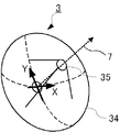
- FIG. 2 is a conceptual diagram showing the interrelationship of antenna mounts according to the first embodiment.
- the antenna 3 includes three drive shafts: an AZ shaft 4, an elevation shaft (hereinafter referred to as EL axis) 5, and a cross elevation shaft (hereinafter referred to as xEL axis) 6.
- the AZ shaft 4 is supported by the base 8 and is rotatable about a vertical line with respect to the base 8.
- the angle of the AZ axis 4 is referred to as the AZ angle
- the angle of the EL axis 5 is referred to as the EL angle
- the angle of the xEL axis 6 is referred to as the xEL angle.
- the AZ axis 4 is mainly responsible for AZ angle tracking of the antenna 3.
- the EL shaft 5 is attached to the AZ shaft 4 and is rotatable around a line orthogonal to the AZ shaft 4 with respect to the AZ shaft 4.
- the EL axis 5 is responsible for EL angle tracking.
- the xEL shaft 6 is attached to the EL shaft 5 and can be rotated within a certain angle range around an axis perpendicular to the EL shaft 5 with respect to the EL shaft 5.
- the rotation angle range of the xEL shaft 6 is smaller than the rotation angle range of the EL shaft 5.
- the antenna 3 is fixed to the xEL shaft 6.
- the beam direction 7 of the antenna 3 can be directed in an arbitrary direction by the AZ axis 4, the EL axis 5, and the xEL axis 6.
- the beam direction 7 of the antenna 3 is controlled by three-axis control for driving the AZ axis 4, EL axis 5 and xEL axis 6, or two-axis control for driving the AZ axis 4 and EL axis 5 to track the target.
- FIG. 3 is a diagram illustrating an example of the antenna according to the first embodiment.
- the antenna 3 includes a main reflecting mirror 34 and a sub reflecting mirror 35.
- the XY coordinate system is a coordinate system fixed to the main reflecting mirror 34.
- the coordinate conversion unit 14 performs coordinate conversion on the angle error signals ⁇ X and ⁇ Y, calculates errors of the AZ angle and the EL angle in the case of biaxial control, and outputs them.
- the AZ command calculation unit 15 calculates a command value for the AZ angle based on the command value for the AZ angle and the actual AZ angle, and outputs it.
- the predicted value acquisition unit 21 acquires an orbit predicted value that is a predicted value of the position of the satellite at each time, and sends it to the program calculation unit 16 and the determination unit 22.
- the predicted trajectory value is composed of an azimuth angle, an elevation angle, and a distance for each time in a drive coordinate system that moves in the inertial coordinate system due to the rotation of the earth and that has the antenna 3 as the origin.
- the distance is a distance from the antenna 3 to the satellite.
- the inertial coordinate system for example, three-dimensional coordinates having the origin at the center of gravity of the earth are used.
- the earth rotates in an inertial coordinate system.
- the inertial coordinates move along the earth's revolution orbit, but can be regarded as inertial coordinates for one period in which a satellite located near the earth orbits the orbit.
- the program calculation unit 16 obtains xEL angle, EL angle, AZ angle in the case of triaxial control, and AZ angle command value (a value that keeps the AZ angle constant) in the case of biaxial control. Calculate each.
- the program calculation unit 16 outputs an error between the command value and the actual angle.
- the tracking system 1 has an automatic tracking mode for controlling the attitude of the antenna 3 based on the satellite signal and a program tracking mode for controlling the attitude of the antenna 3 based on the predicted trajectory value.
- the arithmetic processing unit 13 When in the automatic tracking mode, the arithmetic processing unit 13 outputs the angle error signal ⁇ X output from the tracking receiver 12, the output of the coordinate conversion unit 14, and the output of the AZ command calculation unit 15 to the switching unit 17.
- the arithmetic processing unit 13 outputs the output of the program arithmetic unit 16 to the switching unit 17 when in the program tracking mode.
- the switching unit 17 switches between two-axis control for driving the AZ axis 4 and the EL axis 5 and three-axis control for driving the AZ axis 4, the EL axis 5, and the xEL axis 6 based on a signal from the determination unit 22.
- Fig. 1 shows the case of performing the 3-axis control in the automatic tracking mode.
- the output of the AZ command calculation unit 15 is supplied to the AZ servo calculation unit 20, and the AZ servo calculation unit 20 performs AZ driving so that there is no AZ angle error.
- Motor drive power is supplied to the unit 33 to drive and control the AZ shaft 4.
- the EL angle error output from the coordinate conversion unit 14 by converting the angle error signals ⁇ X and ⁇ Y is supplied to the EL servo calculation unit 19, and the EL servo calculation unit 19 eliminates the EL angle error.
- Motor drive power is supplied to 32 to drive and control the EL shaft 5.
- the angle error signal ⁇ X is supplied to the xEL servo calculation unit 18, and the xEL servo calculation unit 18 supplies motor drive power to the xEL drive unit 31 so as to eliminate the error of the xEL angle, thereby driving and controlling the xEL shaft 6.
- the output of the coordinate conversion unit 14 is supplied to the AZ servo calculation unit 20 and the EL servo calculation unit 19, and the AZ servo calculation unit 20 and the EL servo calculation unit 19
- the AZ axis 4 and the EL axis 5 are driven and controlled so that there are no errors in the AZ angle and EL angle.
- the error amounts of the AZ angle, EL angle, and xEL angle in the case of three-axis control output from the program calculation unit 16 are the AZ servo calculation unit 20, It is supplied to the EL servo calculation unit 19 and the xEL servo calculation unit 18.
- the AZ servo calculation unit 20, the EL servo calculation unit 19, and the xEL servo calculation unit 19 drive and control the AZ axis 4, the EL axis 5, and the xEL axis 6 so that errors of the AZ angle, the EL angle, and the xEL angle are eliminated.
- the error amounts of the AZ angle and EL angle in the case of 2-axis control output from the program calculation unit 16 are respectively the AZ servo calculation unit 20 and the EL servo calculation.
- the AZ servo calculation unit 20 and the EL servo calculation unit 19 drive and control the AZ axis 4 and the EL axis 5 so as to eliminate the errors of the AZ angle and the EL angle, respectively.
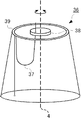
- FIG. 4 is a perspective view of the cable winding mechanism in the first embodiment.
- the side surface of the casing of the cable winding mechanism 36 is represented by a dotted line.
- Each of the cables 37 for sending electric power or signals is bent into a U-shape, and the U-shaped ends are fixed to the rotating portion 38 and the fixed portion 39.
- the rotating part 38 rotates about the AZ axis 4 with respect to the fixed part 39 as indicated by an arrow.
- FIG. 5 is a perspective view of the cable winding mechanism in the first embodiment. For ease of understanding, only one cable 37 is shown.
- FIG. 6 is a perspective view of the cable winding mechanism in which the AZ axis is rotated 45 degrees in the first embodiment.
- FIG. 7 is a perspective view of the cable winding mechanism in which the AZ axis is rotated 180 degrees in the first embodiment.
- FIG. 8 is a perspective view of the cable winding mechanism in which the AZ axis is rotated 270 degrees in the first embodiment. 6 to 8 show a state where the rotating portion 38 of the cable winding mechanism 36 shown in FIG. 5 is rotated in the direction of the arrow.
- the cable winding mechanism 36 shown in FIG. 5 it can be seen that the cable 37 is twisted as the rotating portion 38 rotates. Depending on the slack of the cable 37, it can rotate around the AZ axis 4 up to a certain angle. However, when the angle exceeds the certain angle, the cable 37 needs to be rewound.
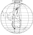
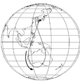
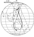
- FIG. 9 is a diagram showing an example of the satellite orbit in the first embodiment.
- the solid line in FIG. 9 indicates the satellite orbit, and the black square indicates the position of the antenna 3.
- the case where the zenith of the antenna 3 is located inside the quasi-zenith orbit will be described as an example.
- the AZ axis 4 and the EL axis 5 of the antenna 3 are driven to make the satellite track the beam direction 7 of the antenna 3 while the satellite goes around the orbit, the AZ angle of the antenna 3 rotates 360 degrees.
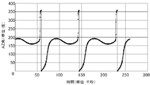
- FIG. 10 and 11 are diagrams showing examples of rotation of the AZ angle.
- the horizontal axis represents time (unit: 1000 seconds), and the vertical axis represents AZ angle (unit: degree).
- the AZ angle when the antenna 3 is directed toward true north is 0 degree
- the AZ angle when the antenna 3 is directed toward true south is 180 degrees.
- FIG. 10 shows the change in the AZ angle when the satellite makes one round of the quasi-zenith orbit
- FIG. When the cable winding mechanism 36 shown in FIG.
- an AZ angle is obtained as shown in FIGS. Rotates 360 degrees or more, and the cable 37 needs to be rewound. When it is necessary to rewind the cable 37, one antenna 3 cannot always communicate with one satellite.
- the tracking system 1 is such that when the AZ angle of the antenna 3 that tracks the satellite within a predetermined time rotates beyond a predetermined rotation range, the estimated position of the satellite is
- the xEL axis 6 can be driven in a state where the AZ angle of the antenna 3 that tracks the AZ angle is a range in which the AZ angle rotates beyond the rotation range from the reference value and the AZ angle is set to a predetermined value that the AZ angle can take. While within the drivable range, the EL axis 5 and the xEL axis 6 are driven with the AZ angle set to a predetermined value, and the beam direction 7 of the antenna 3 is tracked by the satellite.
- the tracking system 1 is configured so that the estimated position of the satellite is not within the drivable range when the AZ angle of the antenna 3 that tracks the satellite within a predetermined time rotates beyond the rotation range, or is determined in advance.
- the AZ angle of the antenna 3 that tracks the satellite in time does not rotate beyond the rotation range, the AZ axis 4 and the EL axis 5 are driven to track the beam direction 7 of the antenna 3 to the satellite.
- the estimated position of the satellite is the estimated position of the satellite or the position of the satellite estimated based on the orbit information of the satellite and the beam direction 7 of the antenna 3.
- the orbit information of the satellite is composed of latitude, longitude, and altitude at each point of the orbit around the satellite.
- the rotation range and the reference value can be arbitrarily determined based on the positional relationship between the antenna 3 and the satellite orbit, the structure of the antenna 3, the length of the cable 37, and the like.
- the rotation determination unit 23 included in the determination unit 22 determines whether or not the AZ angle of the antenna 3 that tracks the satellite rotates beyond the rotation range within a predetermined time based on the orbit prediction value.
- the orbit determination unit 24 included in the determination unit 22 determines that the estimated position of the satellite is the AZ angle of the antenna 3 from the reference value. It is determined whether or not the rotation range exceeds the rotation range and the AZ angle is within a drivable range in which the xEL shaft 6 can be driven in a state where the AZ angle is set to a predetermined value that can be taken by the AZ angle.
- the determination unit 22 When the AZ angle of the antenna 3 rotates beyond the rotation range within a predetermined time, the determination unit 22 performs three-axis control on the switching unit 17 while the estimated satellite position is within the drivable range. A command to be performed is sent, and a command is sent to the AZ command calculation unit 15 to output a command value such that the AZ angle is held at a predetermined value.
- the predetermined value can be arbitrarily determined.
- the determination unit 22 determines that the estimated position of the satellite is not within the above-described driveable range or the AZ angle of the antenna 3 is within the rotation range when the AZ angle of the antenna 3 rotates beyond the rotation range within a predetermined time. When the rotation does not exceed this value, a command for causing the switching unit 17 to perform the two-axis control is sent.
- the determination unit 22 sends a command to the brake device when the estimated position of the satellite enters the drivable range,
- the AZ axis 4 of the antenna 3 may be held by a device. Thereafter, when the estimated position of the satellite is out of the above range, the determination unit 22 sends a command to the brake device to release the brake.
- the switching unit 17 switches between 2-axis control and 3-axis control in accordance with a command from the determination unit 22.
- the AZ command calculation unit 15 outputs a command value such that the AZ angle of the antenna 3 is held at a predetermined value in accordance with the command from the determination unit 22.
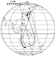
- FIG. 12 is a diagram illustrating an example of the positional relationship between the antenna and the satellite orbit in the first embodiment.
- a dotted line in FIG. 12 indicates the satellite orbit, and a black square indicates the position of the antenna 3.
- the satellite orbits the quasi-zenith orbit in the direction of the arrow. As shown in FIG.
- the rotation determination unit 23 determines that the AZ angle of the antenna 3 does not rotate more than 360 degrees in one day, The determination unit 22 sends a command for causing the switching unit 17 to perform biaxial control based on the AZ axis 4 and the EL axis 5.
- the tracking system 1 drives the AZ axis 4 and the EL axis 5 to cause the satellite to track the beam direction 7 of the antenna 3.
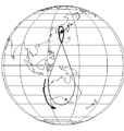
- FIG. 13 is a diagram showing an example of the positional relationship between the antenna and the satellite orbit in the first embodiment.
- a solid line and a dotted line in FIG. 13 indicate the satellite orbit, and a black square indicates the position of the antenna 3.
- the satellite orbits the quasi-zenith orbit in the direction of the arrow.
- the rotation determination unit 23 determines that the AZ angle of the antenna 3 rotates 360 degrees or more in one day.
- the AZ angle when the antenna 3 points to A and B is 180 degrees.
- a range surrounded by a one-dot chain line is a range in which the xEL axis 6 can be driven in a state where the AZ angle is 180 degrees.
- the AZ angle of the antenna 3 rotates from the reference value of 180 degrees to 360 degrees, and the xEL shaft 6 can be driven. Since the rotation determining unit 23 determines that the AZ angle of the antenna 3 rotates 360 degrees or more in one day, the orbit determining unit 24 determines that the estimated position of the satellite is from point A to point B indicated by a solid line in FIG. It is determined whether it is within the range.
- the determination unit 22 sends a command for causing the switching unit 17 to perform 3-axis control, and sends the command to the AZ command calculation unit 15.
- a command is sent to output a command value such that the AZ angle of the antenna 3 is held at a predetermined value.
- the predetermined value 180 degrees is used in the example of FIG.
- the determination unit 22 sends a command for causing the switching unit 17 to perform two-axis control while the estimated position of the satellite is within the range indicated by the dotted line in FIG.
- the tracking system 1 allows the EL axis 5 with the AZ angle to be a predetermined value while the estimated position of the satellite is in the range indicated by the solid line in FIG. 13. And the xEL axis 6 are driven to track the beam direction 7 of the antenna 3 to the satellite, and the AZ axis 4 and the EL axis 5 are driven while the estimated position of the satellite is in the range indicated by the dotted line in FIG. The beam direction 7 of the antenna 3 is tracked by the satellite.
- 14 to 18 are diagrams showing examples of the positional relationship between the antenna and the satellite orbit in the first embodiment.
- the view of the figure is the same as in FIG. 13, and in FIGS. 14 to 16, the zenith of the antenna 3 is located inside the quasi-zenith orbit.
- the quasi-zenith orbit is located at the zenith of the antenna 3.
- the AZ angle of the antenna 3 rotates 360 degrees or more in one day. Therefore, as in FIG. 13, the tracking system 1 determines the AZ angle in advance while the estimated position of the satellite is in the range from point A to point B or from point A to point A indicated by the solid line.
- the EL axis 5 and the xEL axis 6 are driven to track the beam direction 7 of the antenna 3 to the satellite, and while the estimated position of the satellite is within the range indicated by the dotted line, the AZ axis 4 and the EL
- the shaft 5 is driven to track the beam direction 7 of the antenna 3 to the satellite.
- the zenith of the antenna 3 is outside the quasi-zenith orbit, and the AZ angle of the antenna 3 does not rotate more than 360 degrees within one day. Therefore, similarly to FIG. 12, the tracking system 1 drives the AZ axis 4 and the EL axis 5 to track the beam direction 7 of the antenna 3 to the satellite.
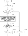
- FIG. 19 is a flowchart illustrating an example of a drive control operation performed by the tracking system according to the first embodiment.
- the rotation determination unit 23 determines whether or not the AZ angle of the antenna 3 rotates beyond the rotation range within a predetermined time based on the predicted trajectory value (step S110). When it is determined that the AZ angle of the antenna 3 rotates beyond the rotation range (step S120; Y), the orbit determination unit 24 determines that the estimated position of the satellite exceeds the rotation range from the reference value. It is determined whether or not the rotation range is within a drivable range in which the xEL axis 6 can be driven with the AZ angle set to a predetermined value (step S130).
- the tracking system 1 sets the AZ angle to a predetermined value by the AZ command calculation unit 15. In this state, the EL axis 5 and the xEL axis 6 are driven to cause the satellite to track the beam direction 7 of the antenna 3 (step S150).
- the trajectory determination unit 24 determines that the AZ angle of the antenna 3 does not rotate beyond the rotation range (step S120; N), or when the rotation determination unit 23 rotates the AZ angle of the antenna 3 beyond the rotation range.
- the tracking system 1 In the case where the orbit determination unit 24 determines that the estimated position of the satellite is not within the drivable range (step S120; Y, step S140; N), the tracking system 1 detects the AZ axis 4 and the EL axis 5. Drive to track the beam direction 7 of the antenna 3 to the satellite (step S160). The tracking system 1 repeats the above process.
- the estimated position of the satellite is a range in which the AZ angle of the antenna 3 that tracks the satellite rotates beyond the rotation range from the reference value.
- FIG. 2 The configuration of tracking system 1 according to Embodiment 2 is the same as that of tracking system 1 according to Embodiment 1 shown in FIG.
- the operation of each part of the tracking system 1 according to the second embodiment, which is different from the first embodiment, will be described.
- the satellite orbits the orbit having the intersection.
- the tracking system 1 is a range in which the estimated position of the satellite reaches the intersection again from the intersection of the satellite orbits when the AZ angle of the antenna 3 that tracks the satellite within a predetermined time rotates beyond the rotation range.
- the antenna 3 is directed to the intersection while the AZ angle is set to the AZ angle when the antenna 3 is directed to the intersection, and the xEL axis 6 is within the driveable range.
- the EL axis 5 and the xEL axis 6 are driven in the state where the AZ angle is set, and the beam direction 7 of the antenna 3 is tracked by the satellite. Therefore, it is not necessary to rewind the cable 37, and one antenna 3 can always communicate with the satellite.
- the AZ angle when the antenna 3 points to the intersection is calculated based on the predicted trajectory value, or the latitude and longitude of the antenna 3 and the orbit information of the satellite.
- the tracking system 1 allows the estimated position of the satellite to fall within the drivable range when the AZ angle of the antenna 3 that tracks the satellite rotates beyond the rotation range within a predetermined time. If the AZ angle of the antenna 3 that tracks the satellite within a predetermined time does not rotate beyond the rotation range, the AZ axis 4 and the EL axis 5 are driven to change the beam direction 7 of the antenna 3. Let the satellite track.
- the rotation determination unit 23 determines whether or not the AZ angle of the antenna 3 rotates beyond the rotation range within a predetermined time based on the predicted trajectory value.
- the orbit determination unit 24 determines that the estimated position of the satellite is within the range from the intersection of the satellite orbits to the intersection again.
- it is determined whether or not the AZ angle is within the drivable range in which the xEL axis 6 can be driven in a state where the AZ angle is the AZ angle when the antenna 3 is directed to the intersection.
- the determination unit 22 When the AZ angle of the antenna 3 rotates beyond the rotation range within a predetermined time, the determination unit 22 performs three-axis control on the switching unit 17 while the estimated satellite position is within the drivable range. A command to be performed is sent, and a command is sent to the AZ command calculation unit 15 to output a command value that holds the AZ angle of the antenna 3 at a predetermined value. In addition, the determination unit 22 determines that the estimated position of the satellite is not within the drivable range when the AZ angle of the antenna 3 rotates beyond the rotation range within a predetermined time, or the AZ angle of the antenna 3 rotates. If the rotation does not exceed the range, a command for causing the switching unit 17 to perform two-axis control is sent.
- FIG. 20 is a diagram showing an example of the positional relationship between the antenna and the satellite orbit in the second embodiment of the present invention.
- a solid line and a dotted line in FIG. 20 indicate the satellite orbit, and a black square indicates the position of the antenna 3.
- the satellite orbits the quasi-zenith orbit in the direction of the arrow.
- the rotation determination unit 23 determines that the AZ angle of the antenna 3 rotates 360 degrees or more in one day.
- a range surrounded by an alternate long and short dash line is a range in which the xEL axis 6 can be driven in a state where the AZ angle is the AZ angle when the antenna 3 is directed to the intersection C.
- the AZ angle of the antenna 3 rotates 360 degrees, and the xEL axis 6 can be driven. Since the rotation determination unit 23 determines that the AZ angle of the antenna 3 rotates 360 degrees or more in one day, the orbit determination unit 24 determines whether or not the estimated position of the satellite is within the range indicated by the solid line in FIG. Determine.
- the AZ command calculation unit 15 provided in the tracking system 1 according to the second embodiment uses the AZ angle when the antenna 3 points to the intersection C as a predetermined value. Further, the determination unit 22 sends a command for causing the switching unit 17 to perform two-axis control while the estimated position of the satellite is within the range indicated by the dotted line in FIG.
- the tracking system 1 changes the AZ angle to the AZ angle when the antenna 3 points to the intersection C while the estimated position of the satellite is in the range indicated by the solid line in FIG.
- the EL axis 5 and the xEL axis 6 are driven to cause the satellite to track the beam direction 7 of the antenna 3.
- the AZ axis 4 and the EL axis 5 are driven to track the beam direction 7 of the antenna 3 to the satellite.
- FIG. 21 to FIG. 23 are diagrams showing an example of the positional relationship between the antenna and the satellite orbit in the second embodiment.
- the zenith of the antenna 3 is located inside the quasi-zenith orbit.
- the quasi-zenith orbit is located at the zenith of the antenna 3.
- the AZ angle of the antenna 3 rotates 360 degrees or more in one day. Therefore, as in FIG. 20, the tracking system 1 allows the antenna 3 to point at the intersection C with the AZ angle while the estimated position of the satellite is in the range from the intersection C indicated by the solid line to the intersection C again.
- the EL axis 5 and the xEL axis 6 are driven in a state where the AZ angle is set so that the beam direction 7 of the antenna 3 is tracked by the satellite, and while the estimated position of the satellite is within the range indicated by the dotted line, the AZ axis 4 and the EL axis 5 are driven to cause the satellite to track the beam direction 7 of the antenna 3.
- step S150 the AZ angle is set to the AZ angle when the antenna 3 points to the intersection C.
- the estimated position of the satellite is in the range from the intersection of the satellite orbit to the intersection again, and the antenna 3 points the intersection at the AZ angle.
- the EL axis 5 and the xEL axis 6 are driven while the AZ angle is set to the AZ angle when the antenna 3 is directed to the intersection while the xEL axis 6 is in a range in which the xEL axis 6 can be driven in the state where the AZ angle is set.
- the target can be tracked without rewinding the cable 37.
- Embodiment 3 The configuration of tracking system 1 according to Embodiment 3 is the same as that of tracking system 1 according to Embodiment 1 shown in FIG. The operation of each part of the tracking system 1 according to the third embodiment, which is different from the first embodiment, will be described.
- the estimated position of the satellite is the antenna 3 that tracks the satellite.
- the AZ angle is not in a range that rotates beyond the rotation range from the reference value, but the xEL shaft 6 can be driven in a state where the AZ angle is set to a predetermined value that the AZ angle can take in the above range.
- the EL axis 5 and the xEL axis 6 are driven to track the beam direction 7 of the antenna 3 to the satellite.
- the estimated position of the satellite can be the AZ angle of the antenna 3 that tracks the satellite.
- the xEL axis 6 can be driven with the predetermined value, the EL axis 5 and the xEL axis 6 are driven and the antenna is driven with the AZ angle set to the predetermined value.
- the beam direction 7 of 3 is tracked by the satellite.
- three-axis control for driving the AZ axis 4, EL axis 5, and xEL axis 6 can be performed in a wider range.
- the rotation determination unit 23 determines whether the AZ angle of the antenna 3 rotates beyond the rotation range within a predetermined time based on the predicted trajectory value.
- the orbit determination unit 24 determines that the estimated position of the satellite is such that the AZ angle of the antenna 3 exceeds the rotation range from the reference value. It is determined whether or not the rotation range is within a drivable range in which the xEL axis 6 can be driven with the AZ angle set to a predetermined value that can be taken by the AZ angle.
- the determination unit 22 When the AZ angle of the antenna 3 rotates beyond the rotation range within a predetermined time, the determination unit 22 performs three-axis control on the switching unit 17 while the estimated satellite position is within the drivable range. A command to be performed is sent, and a command is sent to the AZ command calculation unit 15 to output a command value that holds the AZ angle of the antenna 3 at a predetermined value.
- the determination unit 22 also determines that the estimated position of the satellite is not within the drivable range when the AZ angle of the antenna 3 rotates beyond the rotation range within a predetermined time, but the AZ angle is the predetermined value.
- the estimated position of the satellite can take the AZ angle in advance. While the xEL axis 6 can be driven in a state where it is set to a predetermined value, a command to perform the 3-axis control is sent to the switching unit 17, and in other cases, the switching unit 17 has two axes. Send a command to perform control.
- FIG. 24 is a diagram showing an example of the positional relationship between the antenna and the satellite orbit in the third embodiment of the present invention.
- a solid line and a dotted line in FIG. 24 indicate the orbit of the satellite, and a black square indicates the position of the antenna 3.
- the satellite orbits the quasi-zenith orbit in the direction of the arrow.
- the rotation determination unit 23 determines that the AZ angle of the antenna 3 does not rotate 360 degrees or more during one day.
- the range surrounded by the alternate long and short dash line is a range in which the xEL axis 6 can be driven in a state where the AZ angle is, for example, an angle when the antenna 3 is directed to the intersection C.
- the determination unit 22 performs control by the xEL axis 6 with the estimated position of the satellite set to a predetermined value that the AZ angle can take.
- the switching unit 17 is controlled in three axes while it is within the range from the intersection C to the intersection C again after passing through the point D, for example, in the range indicated by the solid line in FIG.
- the determination unit 22 sends a command for causing the switching unit 17 to perform two-axis control while the estimated position of the satellite is in a range where control by the xEL axis 6 is not possible, that is, in an orbit indicated by a dotted line in FIG.
- the tracking system 1 has a range from the intersection C to the intersection C again after the estimated position of the satellite passes the point D in the range indicated by the solid line in FIG. During this period, the AZ axis 4, EL axis 5 and xEL axis 6 are driven to track the beam direction 7 of the antenna 3 to the satellite. Further, while the estimated position of the satellite is in the range from the intersection C to the point E indicated by the solid line in FIG. 24, the range indicated by the dotted line, and the range from the point D to the intersection C, the AZ axis 4 and the EL axis 5 To track the beam direction 7 of the antenna 3 to the satellite.
- the control is performed in the same manner as in the first or second embodiment.
- FIG. 25 is a flowchart illustrating an example of a drive control operation performed by the tracking system according to the third embodiment. Steps S110 to S150 are the same as the drive control operation performed by the tracking system 1 according to the first embodiment shown in FIG.
- the AZ angle of the antenna 3 rotates beyond the rotation range (step S120; Y)
- the estimated position of the satellite is not in the drivable range (step S140; N), but the AZ angle is set to a predetermined value. If the xEL axis 6 can be driven in a state where the driving is possible (step S151; Y), or if the AZ angle of the antenna 3 does not rotate beyond the rotation range (step S120; N), the satellite is estimated.
- the tracking system 1 uses the AZ command calculation unit 15 With the AZ angle set to a predetermined value, the EL axis 5 and the xEL axis 6 are driven to track the beam direction 7 of the antenna 3 on the satellite (step S150). If the xEL axis 6 cannot be driven (step S151; N), the tracking system 1 drives the AZ axis 4 and the EL axis 5 to track the beam direction 7 of the antenna 3 on the satellite (step S160). The tracking system 1 repeats the above process.
- the estimated position of the satellite is a range in which the AZ angle of the antenna 3 that tracks the satellite rotates beyond the rotation range from the reference value. While the angle is set to a predetermined value, the EL axis 5 and the xEL axis 6 are driven by setting the AZ angle to a predetermined value while the xEL axis 6 is within a driveable range. The target can be tracked without rewinding the cable 37.
- the estimated position of the satellite is not within the drivable range, but the xEL axis 6 can be driven with the AZ angle set to a predetermined value.
- the AZ angle when the AZ angle does not rotate beyond the rotation range from the reference value, while the AZ angle is set to a predetermined value that can be taken by the AZ angle, the AZ angle is within a range in which the xEL shaft 6 can be driven.
- the EL axis 5 and the xEL axis 6 are driven with the angle set to a predetermined value. Therefore, for example, even when the zenith of the antenna 3 is outside the quasi-zenith orbit, 3-axis control is possible, and 3-axis control is possible in a wider range.
- the embodiment of the present invention is not limited to the above-described embodiment, and may be configured by arbitrarily combining a plurality of the above-described embodiments.
- the tracking system 1 may be configured to have only one of the automatic tracking mode and the program tracking mode.
- the orbit that the satellite orbits is not limited to the quasi-zenith orbit and is arbitrary.
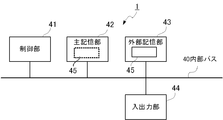
- FIG. 26 is a block diagram showing a physical configuration example of the tracking system according to the embodiment of the present invention.
- the tracking system 1 includes a control unit 41, a main storage unit 42, an external storage unit 43, and an input / output unit 44.
- the main storage unit 42, the external storage unit 43, and the input / output unit 44 are all connected to the control unit 41 via the internal bus 40.
- the control unit 41 includes a CPU (Central Processing Unit) and the like, and executes processing for tracking the target performed by the tracking system 1 in accordance with a control program 45 stored in the external storage unit 43.
- the main storage unit 42 includes a RAM (Random-Access Memory) or the like, loads a control program 45 stored in the external storage unit 43, and is used as a work area for the control unit 41.
- the external storage unit 43 includes a non-volatile memory such as a flash memory, a hard disk, a DVD-RAM (Digital Versatile Disc Random-Access Memory), a DVD-RW (Digital Versatile Disc Disc ReWritable), and the above processing is performed by the control unit 41.
- a control program 45 to be executed is stored in advance, and data stored in the control program 45 is supplied to the control unit 41 in accordance with an instruction from the control unit 41, and the data supplied from the control unit 41 is stored.
- the input / output unit 44 includes a serial interface or a parallel interface.
- An external device is connected to the input / output unit 44.
- the predicted value acquisition unit 21 included in the tracking system 1 acquires a predicted trajectory value from the external device.
- control program 45 is executed by the control program 45 using the control unit 41, the main storage unit 42, the external storage unit 43, the input / output unit 44, and the like as resources.
- the central part that performs control processing including the control unit 41, the main storage unit 42, the external storage unit 43, the internal bus 40, and the like can be realized using a normal computer system, not a dedicated system.
- a computer program for executing the above operation is stored and distributed in a computer-readable recording medium (flexible disk, CD-ROM, DVD-ROM, etc.), and the computer program is installed in the computer.
- the tracking system 1 that executes the above-described processing may be configured. Further, the tracking system 1 may be configured by storing the computer program in a storage device included in a server device on a communication network such as the Internet and downloading it by a normal computer system.
- the functions of the tracking system 1 are realized by sharing an OS (operating system) and an application program or by cooperation between the OS and the application program, only the application program portion is stored in a recording medium or a storage device. May be.
- the computer program may be posted on a bulletin board (BBS: Bulletin Board System) on a communication network, and the computer program may be distributed via the network.
- BSS Bulletin Board System
- the computer program may be started and executed in the same manner as other application programs under the control of the OS, so that the above-described processing may be executed.
- 1 tracking system 2 tracking unit, 3 antenna, 4 AZ axis, 5 EL axis, 6 xEL axis, 7 beam direction, 8 base, 11 feeding device, 12 tracking receiver, 13 arithmetic processing unit, 14 coordinate conversion unit, 15 AZ command calculation unit, 16 program calculation unit, 17 switching unit, 18 xEL servo calculation unit, 19 EL servo calculation unit, 20 AZ servo calculation unit, 21 predicted value acquisition unit, 22 determination unit, 23 rotation determination unit, 24 orbit determination Unit, 31 xEL drive unit, 32 EL drive unit, 33 AZ drive unit, 34 main reflector, 35 sub-reflector, 36 cable winding mechanism, 37 cable, 38 rotating unit, 39 fixing unit, 40 internal bus, 41 control Part, 42 main storage part, 43 external storage part, 44 input / output part, 45 control program.
Landscapes
- Physics & Mathematics (AREA)
- Engineering & Computer Science (AREA)
- General Physics & Mathematics (AREA)
- Radar, Positioning & Navigation (AREA)
- Remote Sensing (AREA)
- Variable-Direction Aerials And Aerial Arrays (AREA)
- Details Of Aerials (AREA)
- Radar Systems Or Details Thereof (AREA)
Abstract
Description
図1は、本発明の実施の形態1に係る追尾システムの構成例を示すブロック図である。追尾システム1は、目標物から信号を受信するように、アンテナ3のビーム方向を目標物に追尾させる。ここで一例として、軌道を周回する衛星を目標物とする。実施の形態1に係る追尾システム1は、衛星を追尾するための各駆動軸の角度指令値または誤差量を演算し、アンテナ3の駆動軸の駆動制御を行う追尾部2、および、2軸制御と3軸制御の切り替えを判定する判定部22を備える。
実施の形態2に係る追尾システム1の構成は、図1に示す実施の形態1に係る追尾システム1の構成と同じである。実施の形態1と異なる、実施の形態2に係る追尾システム1の各部の動作について説明する。
実施の形態3に係る追尾システム1の構成は、図1に示す実施の形態1に係る追尾システム1の構成と同じである。実施の形態1と異なる、実施の形態3に係る追尾システム1の各部の動作について説明する。
Claims (7)
- 目標物から信号を受信するように、アンテナの駆動軸を駆動して前記アンテナのビーム方向を前記目標物に追尾させる追尾システムであって、
各時刻における前記目標物の位置の予測値である軌道予測値に基づき、予め定められた時間内に、前記目標物を追尾する前記アンテナのアジマス角が予め定められた回転範囲を超えて回転するか否かを判定する回転判定部と、
前記回転判定部で前記回転範囲を超えて回転すると判定された場合には、前記軌道予測値、または、前記目標物の軌道情報および前記アンテナのビーム方向、に基づく前記目標物の推定位置が、前記アジマス角が基準値から前記回転範囲を超えて回転する範囲であって、前記駆動軸のアジマス軸の角度を前記アジマス角が取り得る予め定められた値にした状態で、前記駆動軸のクロスエレベーション軸の駆動が可能である駆動可能範囲にあるか否かを判定する軌道判定部と、
前記回転判定部で前記回転範囲を超えて回転すると判定された場合に前記推定位置が前記駆動可能範囲にある間は、前記アジマス軸の角度を前記予め定められた値にした状態で、前記受信した信号に基づき生成された前記アンテナのビーム方向の誤差を示す角度誤差信号、または前記軌道予測値に応じて、前記駆動軸のエレベーション軸および前記クロスエレベーション軸を駆動して前記アンテナのビーム方向を前記目標物に追尾させ、前記回転判定部で前記回転範囲を超えて回転すると判定された場合に前記推定位置が前記駆動可能範囲にない間、または前記回転判定部で前記回転範囲を超えて回転しないと判定された場合には、前記角度誤差信号または前記軌道予測値に応じて、前記アジマス軸および前記エレベーション軸を駆動して前記アンテナのビーム方向を前記目標物に追尾させる追尾部と、
を備える追尾システム。 - 前記目標物は交点を有する軌道を周回し、
前記軌道判定部は、前記駆動可能範囲の、前記アジマス角が基準値から前記回転範囲を超えて回転する範囲を、前記交点から再度前記交点に至るまでの範囲とし、
前記追尾部は、前記回転判定部で前記回転範囲を超えて回転すると判定された場合に前記推定位置が前記駆動可能範囲にある間は、前記アジマス軸の角度を前記アンテナが前記交点を指向する際の前記アジマス軸の角度にした状態で、前記角度誤差信号または前記軌道予測値に応じて、前記エレベーション軸および前記クロスエレベーション軸を駆動して前記アンテナのビーム方向を前記目標物に追尾させ、前記回転判定部で前記回転範囲を超えて回転すると判定された場合に前記推定位置が前記駆動可能範囲にない間、または前記回転判定部で前記回転範囲を超えて回転しないと判定された場合には、前記角度誤差信号または前記軌道予測値に応じて、前記アジマス軸および前記エレベーション軸を駆動して前記アンテナのビーム方向を前記目標物に追尾させる、
請求項1に記載の追尾システム。 - 前記追尾部は、前記回転判定部で前記回転範囲を超えて回転すると判定された場合に前記推定位置が前記駆動可能範囲にないが、前記アジマス軸の角度を前記予め定められた値にした状態で前記クロスエレベーション軸の駆動が可能である範囲にある間は、前記アジマス軸の角度を該予め定められた値にした状態で、前記回転判定部で前記回転範囲を超えて回転しないと判定された場合において、前記推定位置が前記アジマス軸の角度を前記アジマス角が取り得る予め定められた値にした状態で前記クロスエレベーション軸の駆動が可能な範囲にある間は、前記アジマス軸の角度を該予め定められた値にした状態で、前記角度誤差信号または前記軌道予測値に応じて、前記エレベーション軸および前記クロスエレベーション軸を駆動して前記アンテナのビーム方向を前記目標物に追尾させる請求項1または2に記載の追尾システム。
- 目標物から信号を受信するように、アンテナの駆動軸を駆動して前記アンテナのビーム方向を前記目標物に追尾させる追尾方法であって、
各時刻における前記目標物の位置の予測値である軌道予測値に基づき、予め定められた時間内に、前記目標物を追尾する前記アンテナのアジマス角が予め定められた回転範囲を超えて回転するか否かを判定する回転判定ステップと、
前記回転判定ステップで前記回転範囲を超えて回転すると判定された場合には、前記軌道予測値、または、前記目標物の軌道情報および前記アンテナのビーム方向、に基づく前記目標物の推定位置が、前記アジマス角が基準値から前記回転範囲を超えて回転する範囲であって、前記駆動軸のアジマス軸の角度を、前記アジマス角が取り得る予め定められた値にした状態で、前記駆動軸のクロスエレベーション軸の駆動が可能である駆動可能範囲にあるか否かを判定する軌道判定ステップと、
前記回転判定ステップで前記回転範囲を超えて回転すると判定された場合に前記推定位置が前記駆動可能範囲にある間は、前記アジマス軸の角度を前記予め定められた値にした状態で、前記受信した信号に基づき生成された前記アンテナのビーム方向の誤差を示す角度誤差信号、または前記軌道予測値に応じて、前記駆動軸のエレベーション軸および前記クロスエレベーション軸を駆動して前記アンテナのビーム方向を前記目標物に追尾させ、前記回転判定ステップで前記回転範囲を超えて回転すると判定された場合に前記推定位置が前記駆動可能範囲にない間、または前記回転判定ステップで前記回転範囲を超えて回転しないと判定された場合には、前記角度誤差信号または前記軌道予測値に応じて、前記アジマス軸および前記エレベーション軸を駆動して前記アンテナのビーム方向を前記目標物に追尾させる追尾ステップと、
を備える追尾方法。 - 前記目標物は交点を有する軌道を周回し、
前記軌道判定ステップにおいて、前記駆動可能範囲の、前記アジマス角が基準値から前記回転範囲を超えて回転する範囲を、前記交点から再度前記交点に至るまでの範囲とし、
前記追尾ステップにおいて、前記回転判定ステップで前記回転範囲を超えて回転すると判定された場合に前記推定位置が前記駆動可能範囲にある間は、前記アジマス軸の角度を前記アンテナが前記交点を指向する際の前記アジマス軸の角度に設定した状態で、前記角度誤差信号または前記軌道予測値に応じて、前記エレベーション軸および前記クロスエレベーション軸を駆動して前記アンテナのビーム方向を前記目標物に追尾させ、前記回転判定ステップで前記回転範囲を超えて回転すると判定された場合に前記推定位置が前記駆動可能範囲にない間、または前記回転判定ステップで前記回転範囲を超えて回転しないと判定された場合には、前記角度誤差信号または前記軌道予測値に応じて、前記アジマス軸および前記エレベーション軸を駆動して前記アンテナのビーム方向を前記目標物に追尾させる、
請求項4に記載の追尾方法。 - 前記追尾ステップにおいて、前記回転判定ステップで前記回転範囲を超えて回転すると判定された場合に前記推定位置が前記駆動可能範囲にないが、前記アジマス軸の角度を前記予め定められた値にした状態で前記クロスエレベーション軸の駆動が可能である範囲にある間は、前記アジマス軸の角度を該予め定められた値にした状態で、前記回転判定ステップで前記回転範囲を超えて回転しないと判定された場合において、前記推定位置が前記アジマス角が取り得る予め定められた値にした状態で前記クロスエレベーション軸の駆動が可能な範囲にある間は、前記アジマス軸の角度を該予め定められた値にした状態で、前記角度誤差信号または前記軌道予測値に応じて、前記エレベーション軸および前記クロスエレベーション軸を駆動して前記アンテナのビーム方向を前記目標物に追尾させる請求項4または5に記載の追尾方法。
- 目標物から信号を受信するように、アンテナの駆動軸を駆動して前記アンテナのビーム方向を前記目標物に追尾させる追尾システムを制御するコンピュータに、
各時刻における前記目標物の位置の予測値である軌道予測値に基づき、予め定められた時間内に、前記目標物を追尾する前記アンテナのアジマス角が予め定められた回転範囲を超えて回転するか否かを判定する回転判定ステップと、
前記回転判定ステップで前記回転範囲を超えて回転すると判定された場合には、前記軌道予測値、または、前記目標物の軌道情報および前記アンテナのビーム方向、に基づく前記目標物の推定位置が、前記アジマス角が基準値から前記回転範囲を超えて回転する範囲であって、前記駆動軸のアジマス軸の角度を、前記アジマス角が取り得る予め定められた値にした状態で、前記駆動軸のクロスエレベーション軸の駆動が可能である駆動可能範囲にあるか否かを判定する軌道判定ステップと、
前記回転判定ステップで前記回転範囲を超えて回転すると判定された場合に前記推定位置が前記駆動可能範囲にある間は、前記アジマス軸の角度を前記予め定められた値にした状態で、前記受信した信号に基づき生成された前記アンテナのビーム方向の誤差を示す角度誤差信号、または前記軌道予測値に応じて、前記駆動軸のエレベーション軸および前記クロスエレベーション軸を駆動して前記アンテナのビーム方向を前記目標物に追尾させ、前記回転判定ステップで前記回転範囲を超えて回転すると判定された場合に前記推定位置が前記駆動可能範囲にない間、または前記回転判定ステップで前記回転範囲を超えて回転しないと判定された場合には、前記角度誤差信号または前記軌道予測値に応じて、前記アジマス軸および前記エレベーション軸を駆動して前記アンテナのビーム方向を前記目標物に追尾させる追尾ステップと、
を実行させるためのプログラム。
Priority Applications (4)
| Application Number | Priority Date | Filing Date | Title |
|---|---|---|---|
| US14/900,500 US10234532B2 (en) | 2013-07-03 | 2014-05-15 | Tracking system, tracking method, and non-transitory computer-readable recording medium storing program |
| JP2015525081A JP6075666B2 (ja) | 2013-07-03 | 2014-05-15 | 追尾システム、追尾方法およびプログラム |
| CN201480038066.8A CN105379013B (zh) | 2013-07-03 | 2014-05-15 | 跟踪系统及跟踪方法 |
| EP14820326.8A EP3018756B1 (en) | 2013-07-03 | 2014-05-15 | Tracking system, tracking method, and program |
Applications Claiming Priority (2)
| Application Number | Priority Date | Filing Date | Title |
|---|---|---|---|
| JP2013-139493 | 2013-07-03 | ||
| JP2013139493 | 2013-07-03 |
Publications (1)
| Publication Number | Publication Date |
|---|---|
| WO2015001848A1 true WO2015001848A1 (ja) | 2015-01-08 |
Family
ID=52143441
Family Applications (1)
| Application Number | Title | Priority Date | Filing Date |
|---|---|---|---|
| PCT/JP2014/062949 Ceased WO2015001848A1 (ja) | 2013-07-03 | 2014-05-15 | 追尾システム、追尾方法およびプログラム |
Country Status (5)
| Country | Link |
|---|---|
| US (1) | US10234532B2 (ja) |
| EP (1) | EP3018756B1 (ja) |
| JP (1) | JP6075666B2 (ja) |
| CN (1) | CN105379013B (ja) |
| WO (1) | WO2015001848A1 (ja) |
Cited By (2)
| Publication number | Priority date | Publication date | Assignee | Title |
|---|---|---|---|---|
| JP2021088320A (ja) * | 2019-12-06 | 2021-06-10 | キヤノン電子株式会社 | 衛星追尾システム、衛星追尾方法、およびプログラム |
| CN116883617A (zh) * | 2023-09-07 | 2023-10-13 | 武汉大学 | 基于校正测高数据构建月球永久阴影区dem的方法和系统 |
Families Citing this family (10)
| Publication number | Priority date | Publication date | Assignee | Title |
|---|---|---|---|---|
| CN106785442B (zh) * | 2016-12-19 | 2020-06-26 | 中云卫星通信有限公司 | 一种车载卫星天线跟踪卫星的方法及系统 |
| US11592515B2 (en) * | 2017-08-23 | 2023-02-28 | Mitsubishi Electric Corporation | Control device |
| CN109738886B (zh) * | 2019-01-11 | 2023-03-31 | 中国船舶重工集团公司第七二四研究所 | 一种旋转相控阵超天线周期数据率目标跟踪方法 |
| KR102195422B1 (ko) * | 2019-09-02 | 2020-12-28 | (주)인텔리안테크놀로지스 | 안테나 제어 방법 및 장치 |
| KR102195419B1 (ko) * | 2019-09-18 | 2020-12-28 | (주)인텔리안테크놀로지스 | 통신 시스템 |
| US12328786B2 (en) | 2020-04-27 | 2025-06-10 | L3Vel, Llc | Network sensing within a wireless mesh network |
| JOP20220279A1 (ar) * | 2020-04-27 | 2023-01-30 | L3Vel Llc | جهاز تركيب لمعدات اتصالات لاسلكية |
| US11742933B1 (en) * | 2020-07-31 | 2023-08-29 | Amazon Technologies, Inc. | Antenna control using real-time sensor fusion |
| CN113788166B (zh) * | 2021-09-16 | 2024-03-15 | 中国科学院国家天文台 | 基于空间物体轨道误差的差速拦截跟踪方法 |
| CN117508666B (zh) * | 2023-12-25 | 2026-03-17 | 中国科学院长春光学精密机械与物理研究所 | 一种在轨高可靠的二维转动机构控制方法及星载软件 |
Citations (5)
| Publication number | Priority date | Publication date | Assignee | Title |
|---|---|---|---|---|
| JPH07202541A (ja) | 1993-12-28 | 1995-08-04 | Natl Space Dev Agency Japan<Nasda> | 3軸制御空中線装置 |
| JPH09284033A (ja) * | 1996-04-19 | 1997-10-31 | Nec Corp | 衛星用アンテナの捕捉制御装置及びその制御方法 |
| JPH1090389A (ja) * | 1996-09-13 | 1998-04-10 | Japan Radio Co Ltd | 衛星通信アンテナ制御装置 |
| JP2001237629A (ja) | 2000-02-25 | 2001-08-31 | Mitsubishi Electric Corp | 衛星追尾アンテナ駆動制御方法、および衛星追尾アンテナ駆動制御装置 |
| JP2002043820A (ja) * | 2000-07-21 | 2002-02-08 | Mitsubishi Electric Corp | アンテナ又はレーダマウント駆動装置 |
Family Cites Families (11)
| Publication number | Priority date | Publication date | Assignee | Title |
|---|---|---|---|---|
| JPS6022803A (ja) | 1983-07-19 | 1985-02-05 | Nec Corp | 衛星追尾空中線制御装置 |
| JPH0665996B2 (ja) | 1984-10-03 | 1994-08-24 | デイエツクスアンテナ株式会社 | パラボラアンテナの自動追尾方法 |
| US4837576A (en) * | 1984-11-16 | 1989-06-06 | Electrospace Systems, Inc. | Antenna tracking system |
| EP0246635B1 (en) * | 1986-05-21 | 1994-03-02 | Nec Corporation | Tracking controller for three-axis mount antenna systems |
| US4994812A (en) | 1988-12-13 | 1991-02-19 | Nippon Steel Corporation | Antenna system |
| JP2594483B2 (ja) | 1991-12-10 | 1997-03-26 | 新日本製鐵株式会社 | 自動追尾式衛星放送受信アンテナ装置 |
| JPH06252625A (ja) | 1993-02-24 | 1994-09-09 | Sanwa Seiki Co Ltd | 静止衛星追尾用車載アンテナ装置 |
| KR100786025B1 (ko) | 1997-08-21 | 2007-12-17 | 소니 가부시끼 가이샤 | 정보 전송 방법 및 텔레비전 방송 수신 장치 |
| JP3419767B2 (ja) | 2001-03-02 | 2003-06-23 | シャープ株式会社 | アンテナ制御装置および制御方法 |
| US7095376B1 (en) * | 2004-11-30 | 2006-08-22 | L3 Communications Corporation | System and method for pointing and control of an antenna |
| KR100798129B1 (ko) | 2006-09-06 | 2008-02-01 | 위월드 주식회사 | 위성 추적 모드 선택형 위성 안테나 시스템 |
-
2014
- 2014-05-15 WO PCT/JP2014/062949 patent/WO2015001848A1/ja not_active Ceased
- 2014-05-15 JP JP2015525081A patent/JP6075666B2/ja active Active
- 2014-05-15 EP EP14820326.8A patent/EP3018756B1/en not_active Not-in-force
- 2014-05-15 US US14/900,500 patent/US10234532B2/en active Active
- 2014-05-15 CN CN201480038066.8A patent/CN105379013B/zh not_active Expired - Fee Related
Patent Citations (5)
| Publication number | Priority date | Publication date | Assignee | Title |
|---|---|---|---|---|
| JPH07202541A (ja) | 1993-12-28 | 1995-08-04 | Natl Space Dev Agency Japan<Nasda> | 3軸制御空中線装置 |
| JPH09284033A (ja) * | 1996-04-19 | 1997-10-31 | Nec Corp | 衛星用アンテナの捕捉制御装置及びその制御方法 |
| JPH1090389A (ja) * | 1996-09-13 | 1998-04-10 | Japan Radio Co Ltd | 衛星通信アンテナ制御装置 |
| JP2001237629A (ja) | 2000-02-25 | 2001-08-31 | Mitsubishi Electric Corp | 衛星追尾アンテナ駆動制御方法、および衛星追尾アンテナ駆動制御装置 |
| JP2002043820A (ja) * | 2000-07-21 | 2002-02-08 | Mitsubishi Electric Corp | アンテナ又はレーダマウント駆動装置 |
Cited By (4)
| Publication number | Priority date | Publication date | Assignee | Title |
|---|---|---|---|---|
| JP2021088320A (ja) * | 2019-12-06 | 2021-06-10 | キヤノン電子株式会社 | 衛星追尾システム、衛星追尾方法、およびプログラム |
| JP7436194B2 (ja) | 2019-12-06 | 2024-02-21 | キヤノン電子株式会社 | 衛星追尾システム、衛星追尾方法、およびプログラム |
| CN116883617A (zh) * | 2023-09-07 | 2023-10-13 | 武汉大学 | 基于校正测高数据构建月球永久阴影区dem的方法和系统 |
| CN116883617B (zh) * | 2023-09-07 | 2023-11-28 | 武汉大学 | 基于校正测高数据构建月球永久阴影区dem的方法和系统 |
Also Published As
| Publication number | Publication date |
|---|---|
| US20170010341A1 (en) | 2017-01-12 |
| EP3018756A4 (en) | 2017-03-01 |
| JP6075666B2 (ja) | 2017-02-08 |
| CN105379013A (zh) | 2016-03-02 |
| EP3018756A1 (en) | 2016-05-11 |
| CN105379013B (zh) | 2017-11-03 |
| JPWO2015001848A1 (ja) | 2017-02-23 |
| US10234532B2 (en) | 2019-03-19 |
| EP3018756B1 (en) | 2018-07-04 |
Similar Documents
| Publication | Publication Date | Title |
|---|---|---|
| JP6075666B2 (ja) | 追尾システム、追尾方法およびプログラム | |
| JP6438655B2 (ja) | 衛星通信アンテナ・システム | |
| JP5840333B1 (ja) | アンテナ制御装置およびアンテナ装置 | |
| US20100256907A1 (en) | Technique to improve navigation performance through carouselling | |
| CN115309174B (zh) | 一种近地轨道卫星编队联合控制的方法及电子设备 | |
| US20090262197A1 (en) | Moving object image tracking apparatus and method | |
| EP3839691A1 (en) | Gimbal control method and device, gimbal, system and storage medium | |
| US20200271269A1 (en) | Method of controlling gimbal, gimbal, and unmanned aerial vehicle | |
| JP7068763B2 (ja) | 衛星コンステレーション形成システム、衛星コンステレーション形成方法、衛星コンステレーション、および地上装置 | |
| KR102195422B1 (ko) | 안테나 제어 방법 및 장치 | |
| CN110945452A (zh) | 云台和无人机控制方法、云台及无人机 | |
| JP6618643B2 (ja) | アンテナ装置、アンテナ制御装置およびアンテナ装置の制御方法 | |
| CN119439145A (zh) | 相控阵地面站多颗卫星跟踪方法、装置、设备及产品 | |
| JP7068765B2 (ja) | 衛星コンステレーション形成システム、衛星コンステレーション形成方法、衛星コンステレーション形成プログラム、および地上装置 | |
| JP2014165511A (ja) | 衛星追尾アンテナシステムおよび衛星追尾アンテナ制御方法 | |
| JP3419767B2 (ja) | アンテナ制御装置および制御方法 | |
| JP2014241531A (ja) | アンテナ制御装置、アンテナ制御方法およびプログラム | |
| KR102731353B1 (ko) | Tle 정보 기반 위성 추적 방법 및 이를 이용하는 시스템 | |
| WO2021230102A1 (ja) | 情報処理装置および情報処理方法 | |
| KR102267614B1 (ko) | 효율적으로 균시차를 보상하기 위한 위성 태양 전지판 구동 장치의 운용을 위한 방법 및 그 장치 | |
| RU2680356C1 (ru) | Способ ориентации навигационного космического аппарата | |
| JP2012170004A (ja) | 3軸望遠鏡の駆動角度制御方法 | |
| CN115258199B (zh) | 基于ftsm的异轨交会的跟踪控制方法、装置及介质 | |
| JPH09284033A (ja) | 衛星用アンテナの捕捉制御装置及びその制御方法 | |
| JPH0626284B2 (ja) | 3軸アンテナ制御方法 |
Legal Events
| Date | Code | Title | Description |
|---|---|---|---|
| 121 | Ep: the epo has been informed by wipo that ep was designated in this application |
Ref document number: 14820326 Country of ref document: EP Kind code of ref document: A1 |
|
| ENP | Entry into the national phase |
Ref document number: 2015525081 Country of ref document: JP Kind code of ref document: A |
|
| WWE | Wipo information: entry into national phase |
Ref document number: 14900500 Country of ref document: US |
|
| WWE | Wipo information: entry into national phase |
Ref document number: 2014820326 Country of ref document: EP |
|
| NENP | Non-entry into the national phase |
Ref country code: DE |