WO2015004713A1 - 内燃機関の制御方法 - Google Patents
内燃機関の制御方法 Download PDFInfo
- Publication number
- WO2015004713A1 WO2015004713A1 PCT/JP2013/068659 JP2013068659W WO2015004713A1 WO 2015004713 A1 WO2015004713 A1 WO 2015004713A1 JP 2013068659 W JP2013068659 W JP 2013068659W WO 2015004713 A1 WO2015004713 A1 WO 2015004713A1
- Authority
- WO
- WIPO (PCT)
- Prior art keywords
- filter
- cylinders
- internal combustion
- combustion engine
- amount
- Prior art date
- Legal status (The legal status is an assumption and is not a legal conclusion. Google has not performed a legal analysis and makes no representation as to the accuracy of the status listed.)
- Ceased
Links
Images



Classifications
-
- F—MECHANICAL ENGINEERING; LIGHTING; HEATING; WEAPONS; BLASTING
- F02—COMBUSTION ENGINES; HOT-GAS OR COMBUSTION-PRODUCT ENGINE PLANTS
- F02D—CONTROLLING COMBUSTION ENGINES
- F02D17/00—Controlling engines by cutting out individual cylinders; Rendering engines inoperative or idling
- F02D17/04—Controlling engines by cutting out individual cylinders; Rendering engines inoperative or idling rendering engines inoperative or idling, e.g. caused by abnormal conditions
-
- F—MECHANICAL ENGINEERING; LIGHTING; HEATING; WEAPONS; BLASTING
- F02—COMBUSTION ENGINES; HOT-GAS OR COMBUSTION-PRODUCT ENGINE PLANTS
- F02D—CONTROLLING COMBUSTION ENGINES
- F02D41/00—Electrical control of supply of combustible mixture or its constituents
- F02D41/02—Circuit arrangements for generating control signals
- F02D41/021—Introducing corrections for particular conditions exterior to the engine
- F02D41/0235—Introducing corrections for particular conditions exterior to the engine in relation with the state of the exhaust gas treating apparatus
-
- F—MECHANICAL ENGINEERING; LIGHTING; HEATING; WEAPONS; BLASTING
- F01—MACHINES OR ENGINES IN GENERAL; ENGINE PLANTS IN GENERAL; STEAM ENGINES
- F01N—GAS-FLOW SILENCERS OR EXHAUST APPARATUS FOR MACHINES OR ENGINES IN GENERAL; GAS-FLOW SILENCERS OR EXHAUST APPARATUS FOR INTERNAL-COMBUSTION ENGINES
- F01N3/00—Exhaust or silencing apparatus having means for purifying, rendering innocuous, or otherwise treating exhaust
- F01N3/02—Exhaust or silencing apparatus having means for purifying, rendering innocuous, or otherwise treating exhaust for cooling, or for removing solid constituents of, exhaust
- F01N3/021—Exhaust or silencing apparatus having means for purifying, rendering innocuous, or otherwise treating exhaust for cooling, or for removing solid constituents of, exhaust by means of filters
-
- F—MECHANICAL ENGINEERING; LIGHTING; HEATING; WEAPONS; BLASTING
- F01—MACHINES OR ENGINES IN GENERAL; ENGINE PLANTS IN GENERAL; STEAM ENGINES
- F01N—GAS-FLOW SILENCERS OR EXHAUST APPARATUS FOR MACHINES OR ENGINES IN GENERAL; GAS-FLOW SILENCERS OR EXHAUST APPARATUS FOR INTERNAL-COMBUSTION ENGINES
- F01N3/00—Exhaust or silencing apparatus having means for purifying, rendering innocuous, or otherwise treating exhaust
- F01N3/08—Exhaust or silencing apparatus having means for purifying, rendering innocuous, or otherwise treating exhaust for rendering innocuous
- F01N3/10—Exhaust or silencing apparatus having means for purifying, rendering innocuous, or otherwise treating exhaust for rendering innocuous by thermal or catalytic conversion of noxious components of exhaust
- F01N3/18—Exhaust or silencing apparatus having means for purifying, rendering innocuous, or otherwise treating exhaust for rendering innocuous by thermal or catalytic conversion of noxious components of exhaust characterised by methods of operation; Control
- F01N3/20—Exhaust or silencing apparatus having means for purifying, rendering innocuous, or otherwise treating exhaust for rendering innocuous by thermal or catalytic conversion of noxious components of exhaust characterised by methods of operation; Control specially adapted for catalytic conversion
-
- F—MECHANICAL ENGINEERING; LIGHTING; HEATING; WEAPONS; BLASTING
- F01—MACHINES OR ENGINES IN GENERAL; ENGINE PLANTS IN GENERAL; STEAM ENGINES
- F01N—GAS-FLOW SILENCERS OR EXHAUST APPARATUS FOR MACHINES OR ENGINES IN GENERAL; GAS-FLOW SILENCERS OR EXHAUST APPARATUS FOR INTERNAL-COMBUSTION ENGINES
- F01N9/00—Electrical control of exhaust gas treating apparatus
- F01N9/002—Electrical control of exhaust gas treating apparatus of filter regeneration
-
- F—MECHANICAL ENGINEERING; LIGHTING; HEATING; WEAPONS; BLASTING
- F02—COMBUSTION ENGINES; HOT-GAS OR COMBUSTION-PRODUCT ENGINE PLANTS
- F02D—CONTROLLING COMBUSTION ENGINES
- F02D41/00—Electrical control of supply of combustible mixture or its constituents
- F02D41/008—Controlling each cylinder individually
- F02D41/0087—Selective cylinder activation, i.e. partial cylinder operation
-
- F—MECHANICAL ENGINEERING; LIGHTING; HEATING; WEAPONS; BLASTING
- F02—COMBUSTION ENGINES; HOT-GAS OR COMBUSTION-PRODUCT ENGINE PLANTS
- F02D—CONTROLLING COMBUSTION ENGINES
- F02D41/00—Electrical control of supply of combustible mixture or its constituents
- F02D41/02—Circuit arrangements for generating control signals
- F02D41/021—Introducing corrections for particular conditions exterior to the engine
- F02D41/0235—Introducing corrections for particular conditions exterior to the engine in relation with the state of the exhaust gas treating apparatus
- F02D41/027—Introducing corrections for particular conditions exterior to the engine in relation with the state of the exhaust gas treating apparatus to purge or regenerate the exhaust gas treating apparatus
- F02D41/029—Introducing corrections for particular conditions exterior to the engine in relation with the state of the exhaust gas treating apparatus to purge or regenerate the exhaust gas treating apparatus the exhaust gas treating apparatus being a particulate filter
-
- F—MECHANICAL ENGINEERING; LIGHTING; HEATING; WEAPONS; BLASTING
- F02—COMBUSTION ENGINES; HOT-GAS OR COMBUSTION-PRODUCT ENGINE PLANTS
- F02D—CONTROLLING COMBUSTION ENGINES
- F02D41/00—Electrical control of supply of combustible mixture or its constituents
- F02D41/02—Circuit arrangements for generating control signals
- F02D41/04—Introducing corrections for particular operating conditions
- F02D41/042—Introducing corrections for particular operating conditions for stopping the engine
-
- F—MECHANICAL ENGINEERING; LIGHTING; HEATING; WEAPONS; BLASTING
- F02—COMBUSTION ENGINES; HOT-GAS OR COMBUSTION-PRODUCT ENGINE PLANTS
- F02D—CONTROLLING COMBUSTION ENGINES
- F02D41/00—Electrical control of supply of combustible mixture or its constituents
- F02D41/30—Controlling fuel injection
- F02D41/3005—Details not otherwise provided for
-
- F—MECHANICAL ENGINEERING; LIGHTING; HEATING; WEAPONS; BLASTING
- F01—MACHINES OR ENGINES IN GENERAL; ENGINE PLANTS IN GENERAL; STEAM ENGINES
- F01N—GAS-FLOW SILENCERS OR EXHAUST APPARATUS FOR MACHINES OR ENGINES IN GENERAL; GAS-FLOW SILENCERS OR EXHAUST APPARATUS FOR INTERNAL-COMBUSTION ENGINES
- F01N2430/00—Influencing exhaust purification, e.g. starting of catalytic reaction, filter regeneration, or the like, by controlling engine operating characteristics
- F01N2430/02—Influencing exhaust purification, e.g. starting of catalytic reaction, filter regeneration, or the like, by controlling engine operating characteristics by cutting out a part of engine cylinders
-
- F—MECHANICAL ENGINEERING; LIGHTING; HEATING; WEAPONS; BLASTING
- F01—MACHINES OR ENGINES IN GENERAL; ENGINE PLANTS IN GENERAL; STEAM ENGINES
- F01N—GAS-FLOW SILENCERS OR EXHAUST APPARATUS FOR MACHINES OR ENGINES IN GENERAL; GAS-FLOW SILENCERS OR EXHAUST APPARATUS FOR INTERNAL-COMBUSTION ENGINES
- F01N2430/00—Influencing exhaust purification, e.g. starting of catalytic reaction, filter regeneration, or the like, by controlling engine operating characteristics
- F01N2430/06—Influencing exhaust purification, e.g. starting of catalytic reaction, filter regeneration, or the like, by controlling engine operating characteristics by varying fuel-air ratio, e.g. by enriching fuel-air mixture
-
- F—MECHANICAL ENGINEERING; LIGHTING; HEATING; WEAPONS; BLASTING
- F02—COMBUSTION ENGINES; HOT-GAS OR COMBUSTION-PRODUCT ENGINE PLANTS
- F02D—CONTROLLING COMBUSTION ENGINES
- F02D2200/00—Input parameters for engine control
- F02D2200/02—Input parameters for engine control the parameters being related to the engine
- F02D2200/08—Exhaust gas treatment apparatus parameters
- F02D2200/0812—Particle filter loading
-
- Y—GENERAL TAGGING OF NEW TECHNOLOGICAL DEVELOPMENTS; GENERAL TAGGING OF CROSS-SECTIONAL TECHNOLOGIES SPANNING OVER SEVERAL SECTIONS OF THE IPC; TECHNICAL SUBJECTS COVERED BY FORMER USPC CROSS-REFERENCE ART COLLECTIONS [XRACs] AND DIGESTS
- Y02—TECHNOLOGIES OR APPLICATIONS FOR MITIGATION OR ADAPTATION AGAINST CLIMATE CHANGE
- Y02T—CLIMATE CHANGE MITIGATION TECHNOLOGIES RELATED TO TRANSPORTATION
- Y02T10/00—Road transport of goods or passengers
- Y02T10/10—Internal combustion engine [ICE] based vehicles
- Y02T10/40—Engine management systems
Definitions
- the present invention relates to a method for controlling an internal combustion engine.
- a filter for collecting particulate matter (hereinafter also referred to as PM) in the exhaust gas may be provided in the exhaust passage of the internal combustion engine.
- PM particulate matter
- a gasoline engine is usually operated at a stoichiometric or rich air-fuel ratio, so the oxygen concentration in the filter is low.
- the oxygen is supplied to the filter only when operating at a lean air-fuel ratio or when a fuel cut is performed by deceleration or the like. Therefore, in a gasoline engine operated at a stoichiometric air-fuel ratio or a rich air-fuel ratio, it is difficult to regenerate the filter only by increasing the engine speed even if the temperature of the filter is equal to or higher than a predetermined temperature.
- the amount of NOx discharged from the internal combustion engine is larger than when the internal combustion engine is operated at a stoichiometric air-fuel ratio or a rich air-fuel ratio.
- a lean air-fuel ratio for example, it becomes difficult to purify NOx by a three-way catalyst provided upstream of the filter. Therefore, when the filter is regenerated by operating at a lean air-fuel ratio, the NOx emission amount may increase.
- the present invention has been made in view of the above-described problems, and an object of the present invention is to increase opportunities for regeneration of the filter while reducing the NOx emission amount.
- the present invention provides: In a control method of an internal combustion engine comprising a plurality of cylinders and a filter that collects particulate matter in an exhaust passage of the internal combustion engine, After there is a request to stop the internal combustion engine and before the internal combustion engine is stopped, fuel supply is stopped in some cylinders and fuel supply is continued in other cylinders for combustion.
- Part cylinder stop process An all cylinder stopping step of stopping the internal combustion engine by stopping fuel supply in all cylinders after the partial cylinder stopping step; It is comprised including.
- ⁇ Torque for operating the internal combustion engine is generated in other cylinders that continue to be supplied with fuel and burn. For this reason, even if the supply of fuel is stopped in some cylinders, the operation of the internal combustion engine continues, and the pistons in the some cylinders continue to move. Since some cylinders are not combusted, the intake air is discharged as it is. That is, oxygen is discharged from some cylinders. By supplying this oxygen to the filter, the particulate matter collected in the filter can be oxidized. That is, the filter is regenerated before the internal combustion engine is stopped. At this time, fuel combustion is not performed in some cylinders, so NOx is not generated in some cylinders.
- the amount of NOx emission can be reduced by stopping the supply of fuel in some cylinders, compared to when supplying fuel to all cylinders. That is, it is possible to regenerate the filter while reducing the NOx emission amount. It is sufficient that spark ignition is performed at least in other cylinders that continue to supply fuel and perform combustion, and in some cylinders that stop supplying fuel, spark ignition may or may not be performed. Also good.
- combustion may be performed near the stoichiometric air-fuel ratio.
- combustion is performed in the vicinity of the stoichiometric air-fuel ratio, whereby generation of NOx in the other cylinders can be suppressed. That is, the amount of NOx emission during filter regeneration can be reduced.
- the exhaust from the other cylinders that perform combustion contains almost no oxygen, but oxygen is exhausted from some of the cylinders, so that the filter can be regenerated.
- the partial cylinder stopping step may be performed when the temperature of the filter is equal to or higher than a predetermined lower limit temperature.
- the particulate matter may be hardly oxidized even if oxygen is supplied to the filter. That is, when the filter temperature is so low that it is difficult to oxidize the particulate matter, the filter is not regenerated even if the supply of fuel is stopped in some cylinders. For this reason, even if the fuel is supplied to the other cylinders and the operation of the internal combustion engine is continued, the fuel is wasted. In such a case, fuel consumption can be reduced by stopping the internal combustion engine without supplying fuel to the other cylinders. On the other hand, if the supply of fuel is stopped in some cylinders when the temperature of the filter is equal to or higher than a predetermined lower limit temperature, the filter can be regenerated without wasting fuel.
- the predetermined lower limit temperature can be a lower limit value of the temperature at which the particulate matter is oxidized.
- the predetermined lower limit temperature may be a value having a certain margin with respect to the lower limit value of the temperature at which the particulate matter is oxidized. That is, the predetermined lower limit temperature may be higher than the lower limit value of the temperature at which the particulate matter is oxidized. Further, the predetermined lower limit temperature may be changed according to, for example, the amount of oxygen supplied.
- the partial cylinder stopping step may be performed when the temperature of the filter is equal to or lower than a predetermined upper limit temperature.
- the filter when the filter is regenerated, the temperature of the filter rises due to the reaction heat of the particulate matter. Therefore, if the filter is regenerated when the temperature of the filter is high, the filter may be overheated. On the other hand, if the temperature of the filter is equal to or lower than the predetermined upper limit temperature, overheating of the filter can be suppressed even if the fuel supply is stopped in some cylinders and the filter is regenerated.
- the predetermined upper limit temperature can be a value larger than the predetermined lower limit temperature. Further, the predetermined upper limit temperature can be an upper limit value of a temperature at which the filter does not overheat even when the filter is regenerated. Further, the predetermined upper limit temperature may be set to a value equal to or lower than a value obtained by subtracting the temperature increase during regeneration of the filter from the heat resistant temperature of the filter. Further, the predetermined upper limit temperature may be a value having a certain margin with respect to the temperature rise during the regeneration of the filter. Further, the predetermined upper limit temperature may be changed according to, for example, the amount of oxygen supplied.
- the partial cylinder stopping step may be performed when the amount of the particulate matter collected in the filter is equal to or greater than a predetermined lower limit amount.
- the amount of the particulate matter collected in the filter is small, the possibility of clogging of the filter is low, and therefore it is not necessary to regenerate the filter. Even in such a case, if the supply of fuel is stopped in some cylinders and the supply of fuel is continued in other cylinders, the fuel is wasted. On the other hand, if the amount of particulate matter collected in the filter is equal to or greater than a predetermined lower limit, the fuel consumption can be reduced by stopping the fuel supply in some cylinders.
- the predetermined lower limit amount can be a lower limit value of the amount of particulate matter that requires regeneration of the filter.
- the partial cylinder stopping step may be performed when the amount of the particulate matter collected in the filter is equal to or less than a predetermined upper limit amount.
- the filter when the filter is regenerated, the temperature of the filter rises due to the reaction heat of the particulate matter. Therefore, if the filter is regenerated when the amount of particulate matter collected in the filter is large, the filter may be overheated. On the other hand, if the amount of particulate matter collected in the filter is less than or equal to a predetermined upper limit amount, even if the fuel supply is stopped in some cylinders and the filter is regenerated. The overheating of the filter can be suppressed.
- the predetermined upper limit amount can be a value larger than the predetermined lower limit amount.
- the predetermined upper limit amount can be, for example, an upper limit value of the amount of the particulate matter that does not overheat even when the filter is regenerated.
- the predetermined upper limit amount may be set to a value equal to or less than a value obtained by subtracting the temperature increase during regeneration of the filter from the heat resistant temperature of the filter.
- the predetermined upper limit amount may be a value having a certain margin with respect to the temperature rise during the regeneration of the filter.
- the predetermined upper limit amount may be changed according to, for example, the amount of oxygen supplied.
- the partial cylinder stopping step is a request for stopping the internal combustion engine after a predetermined operating time has elapsed from the time when the gas having an air / fuel ratio higher than the stoichiometric air / fuel ratio is finally discharged from the internal combustion engine. It may be carried out when there is.
- the regeneration of the filter is performed. In this case, it is not necessary to stop the fuel supply in some cylinders after the internal combustion engine is requested to stop. In such a case, if the fuel supply is stopped in some cylinders and the fuel supply is continued in other cylinders, the fuel is wasted. On the other hand, even if the lean air-fuel ratio exhaust gas is discharged from the internal combustion engine and the filter is regenerated, if the operation time of the internal combustion engine thereafter is long, particulate matter is again collected by the filter.
- the fuel in some cylinders is limited to when there is a request to stop the internal combustion engine after a predetermined operating time has elapsed since the last time the gas having an air / fuel ratio higher than the stoichiometric air / fuel ratio was discharged from the internal combustion engine. If the supply of fuel is stopped, the amount of fuel consumption can be reduced.
- the predetermined operating time is the amount that the amount of particulate matter collected by the filter after the gas having an air / fuel ratio higher than the stoichiometric air / fuel ratio is discharged from the internal combustion engine needs to be regenerated. It can be the time to become.
- the number of cylinders for stopping fuel supply is determined based on at least one of the temperature of the filter or the amount of particulate matter collected in the filter. be able to.
- the number of cylinders for stopping the fuel supply is determined based on the temperature of the filter or at least one of the particulate matter collected in the filter, the regeneration of the filter can be performed more appropriately.
- the lower the temperature of the filter the larger the number of cylinders whose fuel supply is stopped.
- the regeneration of the filter can be completed more quickly by supplying more oxygen.
- the temperature of the filter is high, it is possible to suppress overheating of the filter by reducing the supply amount of oxygen.
- the margin until the filter is clogged is small.
- the amount of particulate matter collected by the filter can be quickly reduced.
- the amount of oxygen required for regeneration of the filter is small, so the amount of oxygen supply may be small.
- torque fluctuations and vibrations may occur.
- the amount of oxygen supplied to the filter is reduced, but the occurrence of torque fluctuations or vibrations can be suppressed.
- the supply of fuel in the partial cylinder stopping step, when the temperature of the filter is equal to or lower than a predetermined temperature, the supply of fuel can be stopped in a plurality of cylinders that are consecutive in the ignition order.
- the filter by stopping the supply of fuel in a plurality of cylinders that are consecutive in the ignition order, the supply of oxygen to the filter is continued, so that the oxidation of the particulate matter can be promoted.
- the oxidation of the particulate matter is promoted when the temperature of the filter is high, the filter may be overheated.
- the temperature of the filter is equal to or lower than the predetermined temperature, even if the fuel supply is stopped in a plurality of cylinders that are consecutive in the ignition order and the filter is regenerated, the filter is overheated. It can suppress that a filter breaks.
- the predetermined temperature can be the upper limit value of the temperature at which the filter does not overheat even if the fuel supply is stopped in a plurality of cylinders that are consecutive in the ignition order. Further, the predetermined temperature may be set to be equal to or less than a value obtained by subtracting the temperature increase during the regeneration of the filter from the heat resistant temperature of the filter. Further, the predetermined temperature may be a value having a certain margin with respect to the temperature rise during the regeneration of the filter.
- the fuel supply in the partial cylinder stopping step, when the temperature of the filter is equal to or higher than a predetermined temperature, the fuel supply can be stopped in a plurality of cylinders that are not consecutive in the ignition order.
- the time during which the supply of oxygen to the filter continues is shortened, so that the oxidation of the particulate matter becomes slow.
- the filter may be overheated. Therefore, the overheating of the filter can be suppressed by slowing the oxidation of the particulate matter.
- the predetermined temperature can be a lower limit value of the temperature at which the filter overheats when the fuel supply is stopped in a plurality of cylinders that are consecutive in the ignition order. Further, the predetermined temperature may be set to be equal to or less than a value obtained by subtracting the temperature increase during the regeneration of the filter from the heat resistant temperature of the filter. Further, the predetermined temperature may be a value having a certain margin with respect to the temperature rise during the regeneration of the filter.
- the partial cylinder stopping step when the amount of particulate matter collected by the filter is a predetermined amount or more, fuel is supplied from a plurality of cylinders that are continuous in the ignition order. Can be stopped.
- the margin until the filter is clogged is small.
- the supply of fuel is stopped in a plurality of cylinders that are consecutive in the ignition order to promote the oxidation of the particulate matter. By doing so, it is possible to suppress clogging of the filter.
- the predetermined amount can be the amount of particulate matter for which it is desirable to perform filter regeneration at an early stage. Further, the predetermined amount may be a lower limit value of the amount of particulate matter that causes clogging of the filter unless the fuel supply is stopped in a plurality of cylinders that are consecutive in the ignition order. The predetermined amount may be a value having a certain margin with respect to the amount of particulate matter that causes clogging of the filter unless the fuel supply is stopped in a plurality of cylinders that are consecutive in the ignition order. . The predetermined amount is the amount of particulate matter when the amount of particulate matter collected by the filter exceeds the allowable range unless the fuel supply is stopped in a plurality of cylinders that are consecutive in the ignition order. It is good.
- the partial cylinder stopping step when the amount of particulate matter collected by the filter is equal to or less than a predetermined amount, fuel is supplied to a plurality of cylinders that are not consecutive in the ignition order. Can be stopped.
- the fuel supply may be stopped in a plurality of cylinders that are not consecutive in the ignition order. If it does so, it can suppress that a torque fluctuation
- the predetermined amount can be an amount of particulate matter that does not cause a problem even if filter regeneration is not performed at an early stage. Further, the predetermined amount can be an upper limit value of the amount of particulate matter that does not cause clogging of the filter even when the fuel supply is stopped in a plurality of cylinders that are not consecutive in the ignition order. The predetermined amount may be a value having a certain margin with respect to the amount of particulate matter that does not cause clogging of the filter even when the fuel supply is stopped in a plurality of cylinders that are not consecutive in the ignition order.
- the exhaust passage of the internal combustion engine is provided with an exhaust purification catalyst having an oxygen storage capability provided upstream of the filter, and an exhaust air exhaust downstream of the exhaust purification catalyst and upstream of the filter.
- a detection device for detecting the fuel ratio, The partial cylinder stopping step can be continued from the time when the air-fuel ratio of the exhaust detected by the detection device becomes higher than the stoichiometric air-fuel ratio until a predetermined period elapses.
- the predetermined period may be a period required for filter regeneration. Further, the predetermined period may be a period required to supply oxygen necessary for regeneration of the filter to the filter.
- FIG. 3 is a flowchart illustrating a control flow of the internal combustion engine according to the first embodiment.
- 6 is a flowchart showing a control flow of an internal combustion engine according to a second embodiment.
- 6 is a flowchart showing a control flow of an internal combustion engine according to a third embodiment.
- 6 is a flowchart showing a control flow of an internal combustion engine according to a fourth embodiment.
- 10 is a flowchart illustrating a control flow of an internal combustion engine according to a fifth embodiment.
- 10 is a flowchart showing a control flow of an internal combustion engine according to a sixth embodiment.
- 14 is a flowchart showing a control flow of an internal combustion engine according to a seventh embodiment. 12 is a flowchart showing a control flow of an internal combustion engine according to an eighth embodiment. 10 is a flowchart showing a control flow of an internal combustion engine according to a ninth embodiment. 14 is a flowchart showing a control flow of an internal combustion engine according to a tenth embodiment. 14 is a flowchart showing a control flow of an internal combustion engine according to an eleventh embodiment. 14 is a flowchart illustrating a control flow of an internal combustion engine according to a twelfth embodiment. 14 is a time chart showing changes in various values according to Example 13. 14 is a flowchart showing a control flow of an internal combustion engine according to a thirteenth embodiment. 18 is a flowchart showing a control flow of an internal combustion engine according to a fourteenth embodiment.
- FIG. 1 is a diagram showing a schematic configuration of an internal combustion engine according to the present embodiment and its intake system and exhaust system.
- An internal combustion engine 1 shown in FIG. 1 is a spark ignition type gasoline engine.
- the internal combustion engine 1 is mounted on a vehicle, for example.
- the internal combustion engine 1 includes a plurality of cylinders.
- the exhaust passage 2 is connected to the internal combustion engine 1.
- a catalyst 3 and a filter 4 for collecting PM in the exhaust are provided in this order from the upstream side.
- Catalyst 3 is a catalyst that purifies exhaust gas.
- the catalyst 3 may be, for example, a three-way catalyst, an oxidation catalyst, an occlusion reduction type NOx catalyst, or a selective reduction type NOx catalyst. In this embodiment, the catalyst 3 is not essential.
- a first temperature sensor 11 for detecting the temperature of the exhaust gas is provided in the exhaust passage 2 upstream of the catalyst 3.
- a second temperature sensor 12 that detects the temperature of the exhaust gas is provided in the exhaust passage 2 downstream from the catalyst 3 and upstream from the filter 4. Based on the detection value of the first temperature sensor 11, the temperature of the catalyst 3 can be detected. Further, the temperature of the filter 4 can be detected based on the detection value of the second temperature sensor 12. Note that the temperatures of the catalyst 3 and the filter 4 can also be estimated based on the operating state of the internal combustion engine 1.
- An air-fuel ratio sensor 13 that detects the air-fuel ratio of the exhaust gas is provided in the exhaust passage 2 downstream of the catalyst 3 and upstream of the filter 4. Instead of the air-fuel ratio sensor 13, an oxygen concentration sensor that detects the oxygen concentration in the exhaust gas may be provided.
- an intake passage 5 is connected to the internal combustion engine 1.
- a throttle 6 for adjusting the intake air amount of the internal combustion engine 1 is provided in the middle of the intake passage 5.
- An air flow meter 14 for detecting the intake air amount of the internal combustion engine 1 is attached to the intake passage 5 upstream of the throttle 6.
- a fuel injection valve 7 for supplying fuel is attached to each cylinder of the internal combustion engine 1.
- the fuel injection valve 7 may inject fuel into the cylinder of the internal combustion engine 1 or may inject fuel into the intake passage 5.
- the internal combustion engine 1 is provided with a spark plug 8 that generates an electric spark in the cylinder.
- the internal combustion engine 1 configured as described above is provided with an ECU 10 that is an electronic control unit for controlling the internal combustion engine 1.
- the ECU 10 controls the internal combustion engine 1 in accordance with the operating conditions of the internal combustion engine 1 and the driver's request.
- the ECU 10 outputs an electric signal corresponding to the amount of depression of the accelerator pedal 16 by the driver to detect the engine load, and an accelerator position sensor 17 for detecting the engine speed. 18 are connected via electric wiring, and output signals of these various sensors are input to the ECU 10.
- a throttle 6, a fuel injection valve 7, and a spark plug 8 are connected to the ECU 10 through electric wiring, and these devices are controlled by the ECU 10.
- the ECU 10 stops the fuel supply in some cylinders before the internal combustion engine 1 is stopped. That is, fuel cut is performed in some cylinders.
- the ECU 10 performs fuel cut in some cylinders after being requested to stop the internal combustion engine 1, and continues to supply fuel in other cylinders for combustion.
- the spark ignition at this time may be performed at least in another cylinder that performs combustion.
- the request to stop the internal combustion engine 1 is, for example, when the driver of the vehicle performs an operation for stopping the internal combustion engine 1 or when the drive source of the vehicle is switched from the internal combustion engine 1 to the electric motor in the hybrid vehicle. This corresponds to a case where the internal combustion engine 1 is automatically stopped regardless of the driver's intention when the vehicle is stopped.
- the case where the driver of the vehicle performs an operation for stopping the internal combustion engine 1 is, for example, a case where the driver of the vehicle turns off the ignition switch.
- the vehicle drive source is switched from the internal combustion engine 1 to the electric motor.
- the internal combustion engine 1 is stopped when the vehicle speed drops to a predetermined speed, and the vehicle is driven by the electric motor. This is the case.
- the case where the internal combustion engine 1 is automatically stopped regardless of the driver's intention when the vehicle is stopped is, for example, the case where the internal combustion engine 1 is automatically stopped when the vehicle is stopped. is there. In the present embodiment, the internal combustion engine 1 is not immediately stopped even after there is a request to stop the internal combustion engine 1.
- Some cylinders that perform fuel cut may be one or more cylinders. Further, the number of cylinders to be subjected to fuel cut may be determined so that the internal combustion engine 1 can operate with other cylinders that continue to supply fuel.
- the fuel cut is performed in some cylinders, and the fuel supply is continued in the other cylinders and combustion is performed, so that the internal combustion engine 1 is operated in the other cylinders in which the fuel supply is continuously performed. Torque is generated to drive the For this reason, even if the supply of fuel is stopped in some cylinders, the operation of the internal combustion engine 1 continues, and the pistons in the some cylinders continue to move. Since some cylinders are combusting, the intake air is discharged as it is. That is, oxygen is discharged from some cylinders. Since the oxygen concentration in the filter 4 can be increased by supplying this oxygen to the filter 4, the regeneration of the filter 4 can be performed.
- the amount of NOx emission can be reduced by performing fuel cut in some cylinders, rather than supplying fuel to all cylinders. That is, it is possible to regenerate the filter while reducing the NOx emission amount. Further, in other cylinders supplying fuel, the amount of NOx generated can be further reduced by operating near the stoichiometric air-fuel ratio or at an air-fuel ratio (rich air-fuel ratio) lower than the stoichiometric air-fuel ratio. Therefore, it can suppress more that NOx is discharged.
- the regeneration of the filter 4 can be performed before the internal combustion engine 1 is stopped. Even after the engine is stopped, the regeneration of the filter 4 is continued if oxygen is present in the filter 4. Therefore, the fuel supply to all the cylinders may be stopped before the regeneration of the filter 4 is completely completed. Alternatively, the fuel supply to all cylinders may be stopped after the regeneration of the filter 4 is completely completed. Further, the supply of fuel to all the cylinders may be stopped after the amount of PM collected by the filter 4 falls within the allowable range. Further, the fuel supply to all the cylinders may be stopped after a predetermined period after the fuel cut is performed in some cylinders.
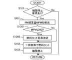
- FIG. 2 is a flowchart showing a control flow of the internal combustion engine 1 according to the present embodiment. This routine is executed by the ECU 10 every predetermined time.
- step S101 it is determined whether there is a request to stop the engine. For example, when the driver turns off the ignition key, it is determined that there is a request to stop the engine. If an affirmative determination is made in step S101, the process proceeds to step S102. On the other hand, if a negative determination is made, this routine is terminated.
- step S102 fuel cut is performed in some cylinders, and fuel supply is continued in other cylinders for combustion. Thereby, the regeneration of the filter 4 is performed.
- step S102 corresponds to the partial cylinder stopping step in the present invention.
- step S103 the internal combustion engine 1 is stopped. That is, the supply of fuel to all cylinders is stopped.
- step S103 corresponds to the all cylinder stopping step in the present invention.
- the fuel is cut in some cylinders before the engine is stopped, and the fuel is continuously supplied to the other cylinders for combustion, whereby oxygen is supplied to the filter 4. Since it can be supplied, the regeneration of the filter 4 can be carried out. Further, by performing fuel cut in some cylinders, it is possible to reduce NOx emission. Further, by performing combustion near the stoichiometric air-fuel ratio in other cylinders that continue to supply fuel, it is possible to further reduce NOx emissions.
- Example 2 The present embodiment is different from the first embodiment in the conditions for performing fuel cut in some cylinders before the engine is stopped. Since other devices are the same as those in the first embodiment, the description thereof is omitted.
- the temperature of the filter 4 needs to be high to some extent. That is, even if oxygen is supplied to the filter 4, it is difficult to regenerate the filter 4 unless the temperature of the filter 4 reaches a temperature at which PM can be oxidized. Therefore, in this embodiment, fuel cut is performed in some cylinders only when the temperature of the filter 4 is equal to or higher than a predetermined lower limit temperature.
- This predetermined lower limit temperature is the lower limit value of the temperature at which PM is oxidized.
- the predetermined lower limit temperature may be a value having a certain margin with respect to the lower limit value of the temperature at which PM is oxidized. That is, the predetermined lower limit temperature may be higher than the lower limit value of the temperature at which PM is oxidized.
- the predetermined lower limit temperature may be changed according to, for example, the amount of oxygen supplied. The amount of oxygen to be supplied may be determined according to the amount of PM collected by the filter 4. Further, the predetermined lower limit temperature can be obtained in advance by experiments or simulations and stored in the ECU 10.
- FIG. 3 is a flowchart showing a control flow of the internal combustion engine 1 according to the present embodiment. This routine is executed by the ECU 10 every predetermined time. Steps in which the same processing as in the above embodiment is performed are denoted by the same reference numerals and description thereof is omitted.
- step S101 if an affirmative determination is made in step S101, the process proceeds to step S201.
- step S201 the temperature TGPF of the filter 4 is detected.
- the temperature TGPF of the filter 4 is detected by the second temperature sensor 12. Further, the temperature TGPF of the filter 4 may be estimated based on the operating state of the internal combustion engine 1.
- step S202 it is determined whether or not the temperature TGPF of the filter 4 is equal to or higher than a predetermined lower limit temperature TA.
- the predetermined lower limit temperature TA is obtained in advance through experiments or simulations as a lower limit value of the temperature at which PM is oxidized, for example, and stored in the ECU 10.
- step S202 If an affirmative determination is made in step S202, the process proceeds to step S102, whereas if a negative determination is made, the process proceeds to step S103.
- the internal combustion engine 1 is stopped without performing fuel cut in some cylinders.
- the fuel supply is not continued in the other cylinders, so that the fuel consumption can be reduced.
- the temperature of the filter 4 is equal to or higher than a predetermined lower limit temperature, the fuel is cut in some cylinders, so that oxygen can be supplied to the filter 4 and the regeneration of the filter 4 can be performed.
- Example 3 The present embodiment is different from the previous embodiment in the conditions for performing fuel cut in some cylinders before the engine is stopped. Since other devices are the same as those in the first embodiment, the description thereof is omitted.
- the filter 4 may be overheated by heat of reaction due to oxidation of PM in the filter 4.
- the filter 4 is damaged, and when the catalyst is supported on the filter 4, the catalyst is deteriorated.
- the predetermined upper limit temperature here is a value larger than the predetermined lower limit temperature according to the second embodiment.
- the predetermined upper limit temperature can be set to an upper limit value of a temperature at which the filter 4 does not overheat even when the filter 4 is regenerated, for example.
- the predetermined upper limit temperature may be set to be equal to or less than a value obtained by subtracting the temperature increase during regeneration of the filter 4 from the heat resistant temperature of the filter 4.
- the predetermined upper limit temperature may be a value having a certain margin with respect to the temperature rise during the regeneration of the filter 4.
- the predetermined upper limit temperature may be changed according to, for example, the amount of oxygen supplied.
- the amount of oxygen to be supplied may be determined in accordance with the amount of PM collected by the filter 4 (hereinafter also referred to as PM collection amount).
- the predetermined upper limit temperature can be obtained in advance by experiments or simulations and stored in the ECU 10.
- FIG. 4 is a flowchart showing a control flow of the internal combustion engine 1 according to the present embodiment. This routine is executed by the ECU 10 every predetermined time. Steps in which the same processing as in the above embodiment is performed are denoted by the same reference numerals and description thereof is omitted.
- step S301 it is determined whether or not the temperature TGPF of the filter 4 is equal to or lower than a predetermined upper limit temperature TB.
- the predetermined upper limit temperature TB is obtained in advance by experiment or simulation as an upper limit value of the temperature at which the filter 4 does not overheat even if the filter 4 is regenerated, and is stored in the ECU 10.
- step S301 If an affirmative determination is made in step S301, the process proceeds to step S102, whereas if a negative determination is made, the process proceeds to step S103.
- the internal combustion engine 1 when the temperature of the filter 4 is higher than the predetermined upper limit temperature, the internal combustion engine 1 is stopped without performing fuel cut in some cylinders. Thereby, damage to the filter 4 and deterioration of the catalyst can be suppressed.
- the temperature of the filter 4 is equal to or lower than a predetermined upper limit temperature, fuel is cut in some cylinders, so that oxygen can be supplied to the filter 4 and the filter 4 can be regenerated. .
- Example 4 The present embodiment is different from the previous embodiment in the conditions for performing fuel cut in some cylinders before the engine is stopped. Since other devices are the same as those in the first embodiment, the description thereof is omitted.
- fuel cut is performed in some cylinders only when the amount of PM collected by the filter 4 is equal to or greater than a predetermined lower limit amount.
- This predetermined lower limit amount can be a lower limit value of the amount of PM collected that requires regeneration of the filter. Further, the predetermined lower limit amount can be obtained in advance through experiments or simulations as a value that can suppress an increase in fuel consumption, and can be stored in the ECU 10.
- FIG. 5 is a flowchart showing a control flow of the internal combustion engine 1 according to the present embodiment. This routine is executed by the ECU 10 every predetermined time. Steps in which the same processing as in the above embodiment is performed are denoted by the same reference numerals and description thereof is omitted.
- step S401 the amount of PM collected by the filter 4 (PM collection amount MPM) is detected.
- the PM collection amount MPM can be detected based on, for example, a differential pressure between the upstream side and the downstream side of the filter 4. Further, the PM collection amount MPM may be estimated based on the operating state of the internal combustion engine 1. Further, the PM collection amount MPM can be simply estimated based on the travel distance of the vehicle and the operation time of the internal combustion engine 1.
- step S402 it is determined whether or not the PM trap amount MPM is equal to or greater than a predetermined lower limit amount MA.
- the predetermined lower limit amount MA is obtained in advance by experiment or simulation or the like and stored in the ECU 10 as a value that can reduce fuel consumption while suppressing clogging of the filter 4, for example.
- step S402 If an affirmative determination is made in step S402, the process proceeds to step S102, whereas if a negative determination is made, the process proceeds to step S103.
- the internal combustion engine 1 is stopped without performing fuel cut in some cylinders. Thereby, although the amount of PM trapped in the filter 4 is small, the supply of fuel does not continue in the other cylinders, so that the fuel consumption can be reduced.
- the amount of PM collected in the filter 4 is equal to or greater than a predetermined lower limit amount, oxygen is supplied to the filter 4 to perform fuel cut in some cylinders, and the filter 4 is regenerated. Can be implemented.
- Example 5 The present embodiment is different from the previous embodiment in the conditions for performing fuel cut in some cylinders before the engine is stopped. Since other devices are the same as those in the first embodiment, the description thereof is omitted.
- the filter 4 may be overheated due to reaction heat due to oxidation of PM in the filter 4.
- the predetermined upper limit amount here is a value larger than the predetermined lower limit amount according to the fourth embodiment.
- the predetermined upper limit amount can be, for example, an upper limit value of the amount of PM that does not overheat even when the filter 4 is regenerated.
- the predetermined upper limit amount may be set to a value equal to or less than a value obtained by subtracting the temperature increase during regeneration of the filter 4 from the heat resistant temperature of the filter 4.
- the predetermined upper limit amount may be a value having a certain margin with respect to the temperature rise during the regeneration of the filter 4.
- the predetermined upper limit amount may be changed according to, for example, the amount of oxygen supplied. Further, the predetermined upper limit amount can be obtained in advance through experiments or simulations and stored in the ECU 10.
- FIG. 6 is a flowchart showing a control flow of the internal combustion engine 1 according to the present embodiment. This routine is executed by the ECU 10 every predetermined time. Steps in which the same processing as in the above embodiment is performed are denoted by the same reference numerals and description thereof is omitted.
- step S501 it is determined whether or not the PM trap amount MPM is equal to or less than a predetermined upper limit amount MB.
- the predetermined upper limit amount MB is obtained in advance by experiments or simulations as an upper limit value of the amount of PM trapped so that the filter 4 does not overheat even if the filter 4 is regenerated, and is stored in the ECU 10.
- step S501 If an affirmative determination is made in step S501, the process proceeds to step S102. On the other hand, if a negative determination is made, the process proceeds to step S103.
- the internal combustion engine 1 is stopped without performing fuel cut in some cylinders. Thereby, damage to the filter 4 and deterioration of the catalyst can be suppressed.
- oxygen is supplied to the filter 4 to regenerate the filter 4 in order to perform fuel cut in some cylinders. Can be implemented.
- Example 6 In this example, a combination of Example 2-4 will be described. Since other devices are the same as those in the first embodiment, the description thereof is omitted.
- the temperature range for performing fuel cut in some cylinders is determined. Further, by using the fourth embodiment and the fifth embodiment, the range of the PM collection amount for performing fuel cut in some cylinders is determined. By combining these, fuel cut in some cylinders can be performed according to the temperature of the filter 4 and the amount of PM trapped.
- FIG. 7 is a flowchart showing a control flow of the internal combustion engine 1 according to the present embodiment. This routine is executed by the ECU 10 every predetermined time. Steps in which the same processing as in the above embodiment is performed are denoted by the same reference numerals and description thereof is omitted.
- step S601 it is determined whether the temperature TGPF of the filter 4 is equal to or higher than the predetermined lower limit temperature TA according to the second embodiment and equal to or lower than the predetermined upper limit temperature TB according to the third embodiment. If an affirmative determination is made in step S601, the process proceeds to step S401, while if a negative determination is made, the process proceeds to step S103.
- step S602. it is determined whether the PM trap amount MPM is equal to or larger than the predetermined lower limit amount MA according to the fourth embodiment and equal to or smaller than the predetermined upper limit amount MB according to the fifth embodiment. If a positive determination is made in step S602, the process proceeds to step S102, whereas if a negative determination is made, the process proceeds to step S103.
- step S401 and step S602 may be performed prior to the processing of step S201 and step S601.
- Example 7 The present embodiment is different from the previous embodiment in the conditions for performing fuel cut in some cylinders before the engine is stopped. Since other devices are the same as those in the first embodiment, the description thereof is omitted.
- the predetermined operation time is the time from when oxygen is supplied to the filter 4 until the amount of collected PM that needs to be regenerated is reached.
- the predetermined operation time may be a value with a certain margin. Further, the predetermined operation time can be obtained in advance through experiments or simulations and stored in the ECU 10.
- FIG. 8 is a flowchart showing a control flow of the internal combustion engine 1 according to the present embodiment. This routine is executed by the ECU 10 every predetermined time. Steps in which the same processing as in the above embodiment is performed are denoted by the same reference numerals and description thereof is omitted.
- step S101 if an affirmative determination is made in step S101, the process proceeds to step S701.
- step S701 it is determined whether or not a predetermined operation time has elapsed since the gas containing a large amount of oxygen was finally discharged from the internal combustion engine 1.
- step S701 it is determined whether or not there is a request to stop the internal combustion engine 1 after a predetermined operation time has elapsed since the gas containing a large amount of oxygen was finally discharged from the internal combustion engine 1. If an affirmative determination is made in step S701, the process proceeds to step S102, whereas if a negative determination is made, the process proceeds to step S103.
- Example 8 when the fuel cut is performed in some cylinders before the engine is stopped, the number of cylinders in which the fuel cut is performed is changed based on at least one of the temperature of the filter 4 and the amount of collected PM. Since other devices are the same as those in the first embodiment, the description thereof is omitted.
- the amount of oxygen supplied to the filter 4 increases as the number of cylinders in which the fuel cut is performed increases. Further, when the amount of collected PM is relatively small, the amount of oxygen required for the oxidation of PM is also small. On the other hand, when the amount of collected PM is relatively large, the amount of oxygen required for oxidation of PM is also large. In addition, when the temperature of the filter 4 is relatively low, the allowance for overheating of the filter 4 is large. On the other hand, when the temperature of the filter 4 is relatively high, the margin for overheating of the filter 4 is small.
- the amount of collected PM increases so that the number of cylinders that perform fuel cut increases or the temperature of the filter 4 decreases, so that the supplied oxygen At least one of increasing the number of cylinders that perform fuel cut is performed so that the amount of the fuel increases.
- the temperature of the filter 4 is equal to or higher than the predetermined lower limit temperature.
- the number of cylinders to be subjected to fuel cut may be determined according to the temperature of the filter 4.
- the number of cylinders that perform fuel cut may be determined according to the amount of PM trapped.
- the number of cylinders to be subjected to fuel cut may be obtained according to the temperature of the filter 4 and the number of cylinders may be corrected according to the amount of PM trapped.
- the number of cylinders to be subjected to fuel cut may be obtained according to the amount of collected PM, and the number of cylinders may be corrected according to the temperature of the filter 4.
- the relationship between the amount of collected PM, the temperature of the filter 4 and the number of cylinders that perform fuel cut may be mapped and stored in the ECU 10. These relationships may be obtained in advance by experiments or simulations.
- FIG. 9 is a flowchart showing a control flow of the internal combustion engine 1 according to the present embodiment. This routine is executed by the ECU 10 every predetermined time. Steps in which the same processing as in the above embodiment is performed are denoted by the same reference numerals and description thereof is omitted.
- step S101 if an affirmative determination is made in step S101, the process proceeds to step S801.
- step S801 the number of cylinders to be subjected to fuel cut is calculated.
- the ECU 10 calculates the number of cylinders to perform fuel cut using a map based on at least one of the temperature of the filter 4 or the amount of collected PM.
- Example 9 when fuel cut is performed in some cylinders before the engine is stopped, if the temperature of the filter 4 is equal to or lower than a predetermined temperature, the fuel cut is performed in a plurality of cylinders that are consecutive in the ignition order. Since other devices are the same as those in the first embodiment, the description thereof is omitted.
- the gas after combustion is supplied to the filter 4 from the other cylinders supplying the fuel, and the cylinders performing the fuel cut Is supplied with oxygen to the filter 4. Therefore, the burned gas and oxygen are supplied to the filter 4 in the order of the cylinder supplying the fuel and the cylinder performing the fuel cut.
- the regeneration of the filter 4 occurs when oxygen from the cylinder that is performing the fuel cut is supplied to the filter 4. Moreover, when the gas after combustion is supplied to the filter 4, generation
- the filter 4 may be overheated by heat of reaction due to oxidation of PM in the filter 4.
- the predetermined temperature here can be an upper limit value of the temperature at which the filter 4 is not overheated even when the fuel supply is stopped in a plurality of cylinders that are continuous in the ignition order. Further, the predetermined temperature may be set to a value equal to or lower than a value obtained by subtracting the temperature increase during regeneration of the filter 4 from the heat-resistant temperature of the filter 4. Further, the predetermined temperature may be a value having a certain margin with respect to the temperature rise during the regeneration of the filter 4.
- the predetermined temperature can be obtained in advance by experiments or simulations and stored in the ECU 10. As described above, when a plurality of cylinders that perform fuel cuts are consecutive in the ignition order, the oxidation of PM is promoted, so that the regeneration of the filter 4 is completed early.
- FIG. 10 is a flowchart showing a control flow of the internal combustion engine 1 according to this embodiment. This routine is executed by the ECU 10 every predetermined time. Steps in which the same processing as in the above embodiment is performed are denoted by the same reference numerals and description thereof is omitted.
- step S901 it is determined whether the temperature TGPF of the filter 4 is equal to or lower than a predetermined temperature TC.
- the predetermined temperature TC is obtained in advance by experiments or simulations as an upper limit value of the temperature at which the filter 4 does not overheat even if the supply of fuel is stopped in a plurality of cylinders that are consecutive in the ignition order, and stored in the ECU 10. Let me. If an affirmative determination is made in step S901, the process proceeds to step S902. On the other hand, if a negative determination is made, the process proceeds to step S102.
- step S902 a cylinder to perform fuel cut is determined. At this time, fuel cut is performed in a plurality of cylinders. And the cylinder which performs a fuel cut is determined so that supply of fuel may be stopped in a plurality of cylinders that are consecutive in the ignition order. The cylinder selected at this time may be obtained in advance by experiments or simulations. The fuel cut may be carried out continuously for three or more cylinders. For example, the lower the temperature of the filter 4, the larger the margin until the filter 4 is overheated, so the number of cylinders that continuously perform fuel cuts may be increased.
- the fuel supply is stopped in a plurality of cylinders that are consecutive in the ignition order, so that the regeneration of the filter 4 is promoted. Can do. Moreover, overheating of the filter 4 can be suppressed.
- Example 10 when fuel cut is performed in some cylinders before the engine is stopped, if the temperature of the filter 4 is equal to or higher than a predetermined temperature, the fuel cut is performed in a plurality of cylinders that are not consecutive in the ignition order. Since other devices are the same as those in the first embodiment, the description thereof is omitted.
- the filter 4 may be overheated by heat of reaction due to oxidation of PM in the filter 4.
- the predetermined temperature here can be a lower limit value of the temperature at which overheating of the filter 4 occurs when the supply of fuel is stopped in a plurality of cylinders that are consecutive in the ignition order. Further, the predetermined temperature may be set to a value equal to or lower than a value obtained by subtracting the temperature increase during regeneration of the filter 4 from the heat-resistant temperature of the filter 4. Further, the predetermined temperature may be a value having a certain margin with respect to the temperature rise during the regeneration of the filter 4.
- the predetermined temperature according to the present embodiment may be the same value as the predetermined temperature according to the ninth embodiment. Further, the predetermined temperature can be obtained in advance by experiments or simulations and stored in the ECU 10. In this way, if the cylinders that perform fuel cut are not continuous in the ignition order, the oxidation of PM becomes slow, so that overheating of the filter 4 can be suppressed.
- FIG. 11 is a flowchart showing a control flow of the internal combustion engine 1 according to the present embodiment. This routine is executed by the ECU 10 every predetermined time. Steps in which the same processing as in the above embodiment is performed are denoted by the same reference numerals and description thereof is omitted.
- step S1001 it is determined whether the temperature TGPF of the filter 4 is equal to or higher than a predetermined temperature TD.
- the predetermined temperature TD is obtained in advance by experiments or simulations as a lower limit value of the temperature at which the filter overheats when the fuel supply is stopped in a plurality of cylinders that are consecutive in the ignition order, for example, and stored in the ECU 10. deep. If an affirmative determination is made in step S1001, the process proceeds to step S1002, while if a negative determination is made, the process proceeds to step S102.
- step S1002 a cylinder to perform fuel cut is determined. At this time, fuel cut is performed in a plurality of cylinders. And the cylinder which performs a fuel cut is determined so that supply of fuel may be stopped in a plurality of cylinders which are not continuous in the ignition order. The cylinder selected at this time may be obtained in advance by experiments or simulations. Further, a plurality of cylinders that do not perform fuel cut may be continued in the ignition order. For example, the higher the temperature of the filter 4, the smaller the margin until the filter 4 is overheated, and the number of cylinders that do not continuously perform fuel cut may be increased.
- oxygen can be supplied to the filter 4 by performing fuel cut in some cylinders before the engine is stopped. Therefore, regeneration of the filter 4 is performed. Can do. Further, when the temperature of the filter 4 is high, the cylinders that perform the fuel cut are not consecutive in the ignition order, so that overheating of the filter 4 can be suppressed.
- Example 11 when fuel cut is performed in some cylinders before the engine is stopped, if the amount of PM trapped is a predetermined amount or more, fuel cut is performed in a plurality of cylinders that are consecutive in the ignition order. Since other devices are the same as those in the first embodiment, the description thereof is omitted.
- the margin until the filter 4 is clogged is small, so it is desirable to reduce the amount of collected PM at an early stage.
- the PM collection amount is a predetermined amount or more
- the fuel supply is stopped in a plurality of cylinders that are consecutive in the ignition order. Then, the cylinder that performs the fuel cut is determined.
- the predetermined amount referred to here can be a PM trapping amount that is desirable to regenerate the filter 4 at an early stage. Further, the predetermined amount may be a lower limit value of the amount of collected PM that causes clogging of the filter 4 unless the fuel supply is stopped in a plurality of cylinders that are consecutive in the ignition order.
- the predetermined amount may be a value having a certain margin with respect to the amount of collected PM that causes clogging of the filter 4 unless the fuel supply is stopped in a plurality of cylinders that are consecutive in the ignition order. . Further, the predetermined amount may be a PM collection amount when the PM collection amount exceeds an allowable range, unless fuel supply is stopped in a plurality of cylinders that are continuous in the ignition order. Further, the predetermined amount can be obtained in advance by experiments or simulations and stored in the ECU 10. Thus, if fuel supply is stopped in a plurality of cylinders that are consecutive in the ignition order, the oxidation of PM is promoted, so that the amount of collected PM can be reduced early.
- FIG. 12 is a flowchart showing a control flow of the internal combustion engine 1 according to the present embodiment. This routine is executed by the ECU 10 every predetermined time. Steps in which the same processing as in the above embodiment is performed are denoted by the same reference numerals and description thereof is omitted.
- step S1101 it is determined whether the PM trap amount MPM is equal to or greater than a predetermined amount MC.
- the predetermined amount MC is obtained in advance by experiments or simulations and stored in the ECU 10. If an affirmative determination is made in step S1101, the process proceeds to step S1102, while if a negative determination is made, the process proceeds to step S102.
- a cylinder to perform fuel cut is determined. At this time, fuel cut is performed in a plurality of cylinders. And the cylinder which implements a fuel cut is determined so that supply of fuel may be stopped in a plurality of cylinders which are continued in the ignition order. The cylinder selected at this time may be obtained in advance by experiments or simulations. Further, the fuel cut may be performed continuously for three or more cylinders. For example, the larger the amount of PM trapped, the smaller the margin for clogging of the filter 4, so the number of cylinders that continuously perform fuel cuts may be increased.
- the supply of fuel is stopped in a plurality of cylinders that are consecutive in the ignition order, so that the regeneration of the filter 4 can be promoted. Moreover, overheating of the filter 4 can be suppressed.
- Example 12 when fuel cut is performed in some cylinders before the engine is stopped, if the amount of PM trapped is equal to or less than a predetermined amount, fuel cut is performed in a plurality of cylinders that are not consecutive in the ignition order. Since other devices are the same as those in the first embodiment, the description thereof is omitted.
- torque decreases. Further, if fuel cut is performed in the cylinders that are consecutive in the ignition order, the torque further decreases, and if torque is subsequently generated in the cylinder that performs fuel injection, vibration may occur.
- the amount of collected PM is equal to or less than a predetermined amount
- fuel supply is stopped in a plurality of cylinders that are not consecutive in the ignition order. Then, the cylinder that performs the fuel cut is determined.
- the predetermined amount here can be a PM trapping amount that does not cause a problem even if the filter 4 is not regenerated at an early stage. Further, the predetermined amount can be the upper limit value of the amount of PM collected so that clogging of the filter 4 does not occur even when the fuel supply is stopped in a plurality of cylinders that are not consecutive in the ignition order.
- the predetermined amount may be a value having a certain margin with respect to the amount of collected PM that does not cause clogging of the filter 4 even when the supply of fuel is stopped in a plurality of cylinders that are not consecutive in the ignition order.
- the predetermined amount is the PM trapping amount when the amount of PM trapped in the filter 4 does not exceed the allowable range even if the fuel supply is stopped in a plurality of cylinders that are not consecutive in the ignition order. It may be collected.
- the predetermined amount according to the present embodiment may be the same value as the predetermined amount according to the eleventh embodiment. Further, the predetermined amount can be obtained in advance by experiments or simulations and stored in the ECU 10. In this way, torque fluctuations and vibrations can be suppressed if the cylinders that perform fuel cut are not consecutive in the ignition order.
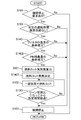
- FIG. 13 is a flowchart showing a control flow of the internal combustion engine 1 according to the present embodiment. This routine is executed by the ECU 10 every predetermined time. Steps in which the same processing as in the above embodiment is performed are denoted by the same reference numerals and description thereof is omitted.
- step S1201 it is determined whether the PM collection amount MPM is equal to or less than a predetermined amount MD.
- the predetermined amount MD is obtained in advance by experiments or simulations and stored in the ECU 10. If an affirmative determination is made in step S1201, the process proceeds to step S1202. On the other hand, if a negative determination is made, the process proceeds to step S102.
- a cylinder to perform fuel cut is determined. At this time, fuel cut is performed in a plurality of cylinders. And the cylinder which performs a fuel cut is determined so that supply of fuel may be stopped in a plurality of cylinders which are not continuous in the ignition order.
- the cylinder selected at this time may be obtained in advance by experiments or simulations. Further, a plurality of cylinders that do not perform fuel cut may be continued in the ignition order. For example, the smaller the amount of PM trapped, the greater the margin until the filter 4 is clogged. Therefore, the number of cylinders that are not continuously subjected to fuel cut may be increased.
- oxygen can be supplied to the filter 4 by performing fuel cut in some cylinders before the engine is stopped. Therefore, regeneration of the filter 4 is performed. Can do.
- the cylinders that perform the fuel cut are not consecutive in the firing order, so that torque fluctuation and vibration can be suppressed.
- the fuel cut in some cylinders is continued for a predetermined period after the air-fuel ratio of the exhaust gas flowing into the filter 4 becomes higher than the stoichiometric air-fuel ratio (lean air-fuel ratio), and then the internal combustion The engine 1 is stopped. Since other devices are the same as those in the first embodiment, the description thereof is omitted.
- the catalyst 3 according to this example is a catalyst having an oxygen storage capacity.
- the catalyst 3 is a three-way catalyst or an occlusion reduction type NOx catalyst.
- the catalyst 3 corresponds to the exhaust purification catalyst in the present invention.
- the regeneration of the filter 4 starts after oxygen flows out from the catalyst 3. Then, fuel is cut in some cylinders for a predetermined period after oxygen flows out of the catalyst 3. If the air-fuel ratio detected by the air-fuel ratio sensor 13 becomes a lean air-fuel ratio, oxygen flows out from the catalyst 3.
- the predetermined period here is a period required for regeneration of the filter 4. That is, the predetermined period is a period required to supply oxygen necessary for regeneration of the filter 4 to the filter 4 and can be obtained in advance by experiments or simulations.
- the air-fuel ratio sensor 13 corresponds to the detection device in the present invention.
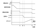
- FIG. 14 is a time chart showing the transition of various values according to this example.
- “Operation request” indicates whether or not there is a request for operating the internal combustion engine 1. When ON, there is a request for operation, and when OFF, there is no request for operation. That is, it can be said that there is a request to stop the internal combustion engine 1 when it is OFF.
- “Engine speed” indicates the speed of the internal combustion engine 1.
- the “number of operating cylinders” indicates the number of other cylinders supplying fuel.
- the air-fuel ratio indicates the detection value of the air-fuel ratio sensor 13.
- the “counter” indicates an integrated value of time from the time when the oxygen stored in the catalyst 3 becomes saturated.
- A indicates the point in time when the operation request changes from ON to OFF.
- Fuel cut is performed in some cylinders from the time indicated by A.
- a time point at which oxygen starts to flow out from the catalyst 3 is indicated by B, and a time point at which the oxygen stored in the catalyst 3 is saturated is indicated by C.
- the counter value is increased.
- the counter indicates an integrated value of time from the time point indicated by C.
- the point in time when the counter reaches the threshold is indicated by D.
- This threshold value is a counter value required for regeneration of the filter 4.
- the internal combustion engine 1 is stopped. That is, the period from C to D corresponds to the predetermined period according to the present embodiment.
- FIG. 15 is a flowchart showing a control flow of the internal combustion engine 1 according to the present embodiment. This routine is executed by the ECU 10 every predetermined time. Steps in which the same processing as in the above embodiment is performed are denoted by the same reference numerals and description thereof is omitted.
- step S1301 it is determined whether or not a predetermined period has elapsed since the detected value of the air-fuel ratio sensor 13 has become a lean air-fuel ratio.
- the predetermined period is obtained in advance by experiment or simulation as a period required for regeneration of the filter 4 and is stored in the ECU 10. If an affirmative determination is made in step S1301, the process proceeds to step S103, whereas if a negative determination is made, the process returns to step S102. That is, step S102 is repeatedly performed until a predetermined period elapses after the lean air-fuel ratio is reached.
- the amount of oxygen necessary for the regeneration of the filter 4 can be supplied to the filter 4 more reliably, so that the regeneration of the filter 4 can be completed more reliably. Can do.
- fuel cuts in some cylinders are not performed more than necessary, fuel consumption can be reduced.
- Example 14 In this embodiment, a combination of Embodiments 1-13 will be described. Since other devices are the same as those in the first embodiment, the description thereof is omitted.
- FIG. 16 is a flowchart showing a control flow of the internal combustion engine 1 according to the present embodiment. This routine is executed by the ECU 10 every predetermined time. Steps in which the same processing as in the above embodiment is performed are denoted by the same reference numerals and description thereof is omitted. FIG. 16 is a combination of all the embodiments 1-13.
- step S1401 it is determined whether the temperature condition of the filter 4 is satisfied. That is, it is determined whether or not the temperature of the filter 4 satisfies a condition for performing fuel cut in some cylinders. In this step, at least one of the processes described in the second embodiment or the third embodiment is performed. If an affirmative determination is made in step S1401, the process proceeds to step S1402. On the other hand, if a negative determination is made, the process proceeds to step S103.
- step S1402 it is determined whether a condition for the amount of PM collected is satisfied. That is, it is determined whether or not the amount of PM trapped satisfies a condition for performing fuel cut in some cylinders. In this step, at least one of the processes described in the fourth embodiment or the fifth embodiment is performed. If an affirmative determination is made in step S1402, the process proceeds to step S801. On the other hand, if a negative determination is made, the process proceeds to step S103.
- step S1403 a cylinder to perform fuel cut is determined. At this time, it is determined whether the cylinders that perform the fuel cut are continuous in the ignition order or not. In this step, at least one of the processes described in the ninth, tenth, eleventh, and twelfth embodiments is performed. When considering both the temperature of the filter 4 and the amount of collected PM, the relationship between the temperature of the filter 4, the amount of collected PM, and the cylinder that performs the fuel cut is determined in advance by experiments or simulations. You may ask for it.
- the filter can be regenerated more appropriately by combining the above embodiments.
- two filters 4 can be provided in parallel.
- One filter 4 is connected to a cylinder that performs fuel cut, and the other filter 4 is connected to a cylinder that continues to supply fuel.
- torque for continuing the operation of the internal combustion engine is generated in the cylinder that continues to supply fuel, and oxygen is supplied to one filter 4 from the cylinder that performs fuel cut.
- the regeneration of the filter 4 is performed in one filter 4.
- the filter 4 connected to the cylinder that performs fuel cut may be switched between one filter 4 and the other filter 4.
- the cylinder that performs fuel cut and the cylinder that continues to supply fuel may be switched.
- the fuel cut may be performed in the cylinder connected to the filter 4 with the larger amount of PM being collected.
Landscapes
- Engineering & Computer Science (AREA)
- Chemical & Material Sciences (AREA)
- Combustion & Propulsion (AREA)
- Mechanical Engineering (AREA)
- General Engineering & Computer Science (AREA)
- Chemical Kinetics & Catalysis (AREA)
- Health & Medical Sciences (AREA)
- Toxicology (AREA)
- Output Control And Ontrol Of Special Type Engine (AREA)
- Electrical Control Of Air Or Fuel Supplied To Internal-Combustion Engine (AREA)
- Processes For Solid Components From Exhaust (AREA)
Abstract
Description
複数の気筒と、内燃機関の排気通路において粒子状物質を捕集するフィルタと、を備える内燃機関の制御方法において、
前記内燃機関を停止させる要求があった後、且つ、前記内燃機関を停止させる前に、一部の気筒において燃料の供給を停止し、他の気筒において燃料の供給を継続して燃焼を行う一部気筒停止工程と、
前記一部気筒停止工程の後に全部の気筒において燃料の供給を停止して前記内燃機関を停止させる全気筒停止工程と、
を含んで構成される。
前記一部気筒停止工程は、前記検出装置により検出される排気の空燃比が理論空燃比よりも高くなった時点から、所定期間が経過するまで継続することができる。
図1は、本実施例に係る内燃機関と、その吸気系及び排気系との概略構成を示す図である。図1に示す内燃機関1は、火花点火式のガソリン機関である。内燃機関1は、たとえば車両に搭載される。また、内燃機関1は複数の気筒を備えている。
本実施例は、機関停止前に一部の気筒において燃料カットを実施する条件が実施例1と異なる。その他の装置等は実施例1と同じため、説明を省略する。
本実施例は、機関停止前に一部の気筒において燃料カットを実施する条件が前記実施例と異なる。その他の装置等は実施例1と同じため、説明を省略する。
本実施例は、機関停止前に一部の気筒において燃料カットを実施する条件が前記実施例と異なる。その他の装置等は実施例1と同じため、説明を省略する。
本実施例は、機関停止前に一部の気筒において燃料カットを実施する条件が前記実施例と異なる。その他の装置等は実施例1と同じため、説明を省略する。
本実施例は、実施例2-4の組み合わせについて説明する。その他の装置等は実施例1と同じため、説明を省略する。
本実施例は、機関停止前に一部の気筒において燃料カットを実施する条件が前記実施例と異なる。その他の装置等は実施例1と同じため、説明を省略する。
本実施例は、機関停止前に一部の気筒において燃料カットを実施するときに、フィルタ4の温度またはPM捕集量の少なくとも一方に基づいて、燃料カットを実施する気筒数を変化させる。その他の装置等は実施例1と同じため、説明を省略する。
本実施例は、機関停止前に一部の気筒において燃料カットを実施する場合に、フィルタ4の温度が所定温度以下の場合には、点火順序で連続する複数の気筒で燃料カットを実施する。その他の装置等は実施例1と同じため、説明を省略する。
本実施例は、機関停止前に一部の気筒において燃料カットを実施する場合に、フィルタ4の温度が所定温度以上の場合には、点火順序で連続しない複数の気筒で燃料カットを実施する。その他の装置等は実施例1と同じため、説明を省略する。
本実施例は、機関停止前に一部の気筒において燃料カットを実施する場合に、PM捕集量が所定量以上の場合には、点火順序で連続する複数の気筒で燃料カットを実施する。その他の装置等は実施例1と同じため、説明を省略する。
本実施例は、機関停止前に一部の気筒において燃料カットを実施する場合に、PM捕集量が所定量以下の場合には、点火順序で連続しない複数の気筒で燃料カットを実施する。その他の装置等は実施例1と同じため、説明を省略する。
本実施例では、一部の気筒における燃料カットを、フィルタ4に流入する排気の空燃比が理論空燃比よりも高い空燃比(リーン空燃比)となってから、所定期間継続させ、その後に内燃機関1を停止させる。その他の装置等は実施例1と同じため、説明を省略する。なお、本実施例に係る触媒3は、酸素吸蔵能力を有する触媒とする。例えば、触媒3は、三元触媒または吸蔵還元型NOx触媒である。そして、本実施例においては触媒3が、本発明における排気浄化触媒に相当する。
本実施例は、実施例1-13の組み合わせについて説明する。その他の装置等は実施例1と同じため、説明を省略する。
2 排気通路
3 触媒
4 フィルタ
5 吸気通路
6 スロットル
7 燃料噴射弁
8 点火プラグ
10 ECU
11 第一温度センサ
12 第二温度センサ
13 空燃比センサ
14 エアフローメータ
16 アクセルペダル
17 アクセル開度センサ
18 クランクポジションセンサ
Claims (15)
- 複数の気筒と、内燃機関の排気通路において粒子状物質を捕集するフィルタと、を備える内燃機関の制御方法において、
前記内燃機関を停止させる要求があった後、且つ、前記内燃機関を停止させる前に、一部の気筒において燃料の供給を停止し、他の気筒において燃料の供給を継続して燃焼を行う一部気筒停止工程と、
前記一部気筒停止工程の後に全部の気筒において燃料の供給を停止して前記内燃機関を停止させる全気筒停止工程と、
を含んで構成される内燃機関の制御方法。 - 前記他の気筒においては、理論空燃比付近で燃焼を行う請求項1に記載の内燃機関の制御方法。
- 前記一部気筒停止工程は、前記フィルタの温度が所定の下限温度以上である場合に実施される請求項1または2に記載の内燃機関の制御方法。
- 前記一部気筒停止工程は、前記フィルタの温度が所定の上限温度以下である場合に実施される請求項1から3の何れか1項に記載の内燃機関の制御方法。
- 前記一部気筒停止工程は、前記フィルタに捕集されている粒子状物質の量が所定の下限量以上である場合に実施される請求項1から4の何れか1項に記載の内燃機関の制御方法。
- 前記一部気筒停止工程は、前記フィルタに捕集されている粒子状物質の量が所定の上限量以下である場合に実施される請求項1から5の何れか1項に記載の内燃機関の制御方法。
- 前記一部気筒停止工程は、理論空燃比よりも高い空燃比のガスが前記内燃機関から最後に排出された時点から所定の運転時間が経過した後に前記内燃機関を停止させる要求があった場合に実施される請求項1から6の何れか1項に記載の内燃機関の制御方法。
- 前記一部気筒停止工程において、前記フィルタの温度または前記フィルタに捕集されている粒子状物質の量の少なくとも一方に基づいて、燃料の供給を停止させる気筒の数を決定する請求項1から7の何れか1項に記載の内燃機関の制御方法。
- 前記一部気筒停止工程において、前記フィルタの温度が低いほど、燃料の供給を停止させる気筒の数を多くする請求項8に記載の内燃機関の制御方法。
- 前記一部気筒停止工程において、前記フィルタに捕集されている粒子状物質の量が多いほど、燃料の供給を停止させる気筒の数を多くする請求項8または9に記載の内燃機関の制御方法。
- 前記一部気筒停止工程において、前記フィルタの温度が所定温度以下である場合に、点火順序で連続している複数の気筒で燃料の供給を停止する請求項1から10の何れか1項に記載の内燃機関の制御方法。
- 前記一部気筒停止工程において、前記フィルタの温度が所定温度以上である場合に、点火順序で連続していない複数の気筒で燃料の供給を停止する請求項1から10の何れか1項に記載の内燃機関の制御方法。
- 前記一部気筒停止工程において、前記フィルタに捕集されている粒子状物質の量が所定量以上である場合に、点火順序で連続している複数の気筒で燃料の供給を停止する請求項1から10の何れか1項に記載の内燃機関の制御方法。
- 前記一部気筒停止工程において、前記フィルタに捕集されている粒子状物質の量が所定量以下である場合に、点火順序で連続していない複数の気筒で燃料の供給を停止する請求項1から10の何れか1項に記載の内燃機関の制御方法。
- 前記内燃機関の排気通路には、前記フィルタよりも上流に設けられる酸素吸蔵能力を有する排気浄化触媒と、前記排気浄化触媒よりも下流で且つ前記フィルタよりも上流における排気の空燃比を検出する検出装置と、を備え、
前記一部気筒停止工程は、前記検出装置により検出される排気の空燃比が理論空燃比よりも高くなった時点から、所定期間が経過するまで継続する請求項1から14の何れか1項に記載の内燃機関の制御方法。
Priority Applications (5)
| Application Number | Priority Date | Filing Date | Title |
|---|---|---|---|
| JP2015526031A JP5999264B2 (ja) | 2013-07-08 | 2013-07-08 | 内燃機関の制御方法 |
| EP13889193.2A EP3020945A4 (en) | 2013-07-08 | 2013-07-08 | CONTROL PROCESS FOR A COMBUSTION ENGINE |
| PCT/JP2013/068659 WO2015004713A1 (ja) | 2013-07-08 | 2013-07-08 | 内燃機関の制御方法 |
| CN201380076841.4A CN105308293A (zh) | 2013-07-08 | 2013-07-08 | 内燃机的控制方法 |
| US14/892,079 US20160115887A1 (en) | 2013-07-08 | 2013-07-08 | Control method for internal combustion engine |
Applications Claiming Priority (1)
| Application Number | Priority Date | Filing Date | Title |
|---|---|---|---|
| PCT/JP2013/068659 WO2015004713A1 (ja) | 2013-07-08 | 2013-07-08 | 内燃機関の制御方法 |
Publications (1)
| Publication Number | Publication Date |
|---|---|
| WO2015004713A1 true WO2015004713A1 (ja) | 2015-01-15 |
Family
ID=52279445
Family Applications (1)
| Application Number | Title | Priority Date | Filing Date |
|---|---|---|---|
| PCT/JP2013/068659 Ceased WO2015004713A1 (ja) | 2013-07-08 | 2013-07-08 | 内燃機関の制御方法 |
Country Status (5)
| Country | Link |
|---|---|
| US (1) | US20160115887A1 (ja) |
| EP (1) | EP3020945A4 (ja) |
| JP (1) | JP5999264B2 (ja) |
| CN (1) | CN105308293A (ja) |
| WO (1) | WO2015004713A1 (ja) |
Cited By (5)
| Publication number | Priority date | Publication date | Assignee | Title |
|---|---|---|---|---|
| WO2018193833A1 (ja) * | 2017-04-21 | 2018-10-25 | 株式会社デンソー | 内燃機関の排気処理装置 |
| JP2020045785A (ja) * | 2018-09-18 | 2020-03-26 | 三菱自動車工業株式会社 | 内燃機関の排気制御装置 |
| JP2022166472A (ja) * | 2021-04-21 | 2022-11-02 | トヨタ自動車株式会社 | 内燃機関の制御装置 |
| JP2023030322A (ja) * | 2021-08-23 | 2023-03-08 | トヨタ自動車株式会社 | 内燃機関の制御装置 |
| JP2023030323A (ja) * | 2021-08-23 | 2023-03-08 | トヨタ自動車株式会社 | 内燃機関の制御装置 |
Families Citing this family (5)
| Publication number | Priority date | Publication date | Assignee | Title |
|---|---|---|---|---|
| JP6673139B2 (ja) * | 2016-10-19 | 2020-03-25 | トヨタ自動車株式会社 | ハイブリッド自動車 |
| DE102018107769A1 (de) * | 2018-04-03 | 2019-10-10 | Dr. Ing. H.C. F. Porsche Aktiengesellschaft | Verfahren für eine Regeneration eines Otto-Partikel-Filters eines Verbrennungsmotors eines Fahrzeugs |
| CN111622845B (zh) * | 2019-02-28 | 2022-08-26 | 本田技研工业株式会社 | 气缸休止系统及气缸休止方法 |
| US11255280B2 (en) * | 2020-01-13 | 2022-02-22 | Denso International America, Inc. | Dual UHEGO control of particulate filter regeneration |
| JP7234956B2 (ja) * | 2020-02-03 | 2023-03-08 | トヨタ自動車株式会社 | 空燃比検出装置の異常検出装置 |
Citations (3)
| Publication number | Priority date | Publication date | Assignee | Title |
|---|---|---|---|---|
| JP2005083306A (ja) | 2003-09-10 | 2005-03-31 | Mazda Motor Corp | エンジンの排気浄化装置 |
| JP2005220880A (ja) * | 2004-02-09 | 2005-08-18 | Toyota Motor Corp | 多気筒内燃機関の制御装置 |
| JP2006083817A (ja) * | 2004-09-17 | 2006-03-30 | Toyota Motor Corp | 内燃機関の排気浄化装置 |
Family Cites Families (10)
| Publication number | Priority date | Publication date | Assignee | Title |
|---|---|---|---|---|
| JP4161812B2 (ja) * | 2003-06-13 | 2008-10-08 | トヨタ自動車株式会社 | 内燃機関の停止制御方法 |
| JP4062229B2 (ja) * | 2003-10-08 | 2008-03-19 | トヨタ自動車株式会社 | 内燃機関の排気浄化装置 |
| JP2009203934A (ja) * | 2008-02-28 | 2009-09-10 | Toyota Motor Corp | 内燃機関の制御装置 |
| US8402751B2 (en) * | 2009-09-29 | 2013-03-26 | Ford Global Technologies, Llc | Particulate filter regeneration in an engine |
| US8336300B2 (en) * | 2009-09-29 | 2012-12-25 | Ford Global Technologies, Llc | System and method for regenerating a particulate filter accompanied by a catalyst |
| US8424295B2 (en) * | 2009-09-29 | 2013-04-23 | Ford Global Technologies, Llc | Particulate filter regeneration during engine shutdown |
| US20110120090A1 (en) * | 2009-11-25 | 2011-05-26 | Sorensen Jr Charles Mitchel | Processes And Devices For Regenerating Gasoline Particulate Filters |
| DE102011015061A1 (de) * | 2011-03-24 | 2012-09-27 | Mann + Hummel Gmbh | Verfahren und Vorrichtung zur Dosierung des Additivs zur Regenerierung eines Dieselpartikelfilters |
| KR101273000B1 (ko) * | 2011-09-02 | 2013-06-10 | 현대자동차주식회사 | Cda 적용 차량의 gpf 손상 방지방법 |
| KR101684496B1 (ko) * | 2011-09-09 | 2016-12-09 | 현대자동차 주식회사 | 배기가스 정화 장치 및 이를 제어하는 방법 |
-
2013
- 2013-07-08 WO PCT/JP2013/068659 patent/WO2015004713A1/ja not_active Ceased
- 2013-07-08 CN CN201380076841.4A patent/CN105308293A/zh active Pending
- 2013-07-08 EP EP13889193.2A patent/EP3020945A4/en not_active Withdrawn
- 2013-07-08 US US14/892,079 patent/US20160115887A1/en not_active Abandoned
- 2013-07-08 JP JP2015526031A patent/JP5999264B2/ja not_active Expired - Fee Related
Patent Citations (3)
| Publication number | Priority date | Publication date | Assignee | Title |
|---|---|---|---|---|
| JP2005083306A (ja) | 2003-09-10 | 2005-03-31 | Mazda Motor Corp | エンジンの排気浄化装置 |
| JP2005220880A (ja) * | 2004-02-09 | 2005-08-18 | Toyota Motor Corp | 多気筒内燃機関の制御装置 |
| JP2006083817A (ja) * | 2004-09-17 | 2006-03-30 | Toyota Motor Corp | 内燃機関の排気浄化装置 |
Non-Patent Citations (1)
| Title |
|---|
| See also references of EP3020945A4 |
Cited By (10)
| Publication number | Priority date | Publication date | Assignee | Title |
|---|---|---|---|---|
| WO2018193833A1 (ja) * | 2017-04-21 | 2018-10-25 | 株式会社デンソー | 内燃機関の排気処理装置 |
| JP2018178981A (ja) * | 2017-04-21 | 2018-11-15 | 株式会社デンソー | 内燃機関の排気処理装置 |
| JP2020045785A (ja) * | 2018-09-18 | 2020-03-26 | 三菱自動車工業株式会社 | 内燃機関の排気制御装置 |
| JP7283043B2 (ja) | 2018-09-18 | 2023-05-30 | 三菱自動車工業株式会社 | 内燃機関の排気制御装置 |
| JP2022166472A (ja) * | 2021-04-21 | 2022-11-02 | トヨタ自動車株式会社 | 内燃機関の制御装置 |
| JP7396325B2 (ja) | 2021-04-21 | 2023-12-12 | トヨタ自動車株式会社 | 内燃機関の制御装置 |
| JP2023030322A (ja) * | 2021-08-23 | 2023-03-08 | トヨタ自動車株式会社 | 内燃機関の制御装置 |
| JP2023030323A (ja) * | 2021-08-23 | 2023-03-08 | トヨタ自動車株式会社 | 内燃機関の制御装置 |
| JP7639614B2 (ja) | 2021-08-23 | 2025-03-05 | トヨタ自動車株式会社 | 内燃機関の制御装置 |
| JP7683418B2 (ja) | 2021-08-23 | 2025-05-27 | トヨタ自動車株式会社 | 内燃機関の制御装置 |
Also Published As
| Publication number | Publication date |
|---|---|
| US20160115887A1 (en) | 2016-04-28 |
| EP3020945A1 (en) | 2016-05-18 |
| EP3020945A4 (en) | 2016-07-06 |
| CN105308293A (zh) | 2016-02-03 |
| JP5999264B2 (ja) | 2016-09-28 |
| JPWO2015004713A1 (ja) | 2017-02-23 |
Similar Documents
| Publication | Publication Date | Title |
|---|---|---|
| JP5999264B2 (ja) | 内燃機関の制御方法 | |
| US9512796B2 (en) | Exhaust purification apparatus for internal combustion engine | |
| US10156174B2 (en) | Methods for mitigating over-temperature during an exhaust gas system particulate filter device regeneration | |
| JP5876714B2 (ja) | 排気ガス浄化装置の制御方法 | |
| CN108301900B (zh) | 内燃机的排气净化装置和内燃机的排气净化方法 | |
| KR20210062696A (ko) | 하이브리드 차량의 입자 필터의 에너지-최적화 강제 재생 | |
| JP2015010470A (ja) | 内燃機関の排気浄化装置 | |
| JP2009203934A (ja) | 内燃機関の制御装置 | |
| JP5915623B2 (ja) | 内燃機関の排気浄化システム | |
| JP2015031166A (ja) | 内燃機関の排気浄化装置 | |
| JP2015052291A (ja) | 内燃機関の排気浄化装置 | |
| JP6237342B2 (ja) | 内燃機関の排気浄化装置 | |
| JP4095979B2 (ja) | 内燃機関の排気浄化装置 | |
| JP4985530B2 (ja) | 内燃機関の制御装置 | |
| JP4033189B2 (ja) | 内燃機関の排気浄化装置 | |
| JP2005113800A (ja) | 内燃機関の排気浄化システム | |
| JP5613477B2 (ja) | パティキュレートフィルタの再生装置 | |
| JP2006274979A (ja) | 排気浄化装置 | |
| JP2006220036A (ja) | フィルタ付きハイブリッドエンジンの制御システム | |
| JP4276525B2 (ja) | 排気浄化装置 | |
| JP2015200204A (ja) | フィルタの再生処理装置 | |
| JP2005113833A (ja) | 内燃機関の触媒温度維持方法 | |
| JP2005155530A (ja) | 排気浄化装置 | |
| JP2017024581A (ja) | ハイブリッド車両 | |
| JP5652292B2 (ja) | 回生システム |
Legal Events
| Date | Code | Title | Description |
|---|---|---|---|
| WWE | Wipo information: entry into national phase |
Ref document number: 201380076841.4 Country of ref document: CN |
|
| 121 | Ep: the epo has been informed by wipo that ep was designated in this application |
Ref document number: 13889193 Country of ref document: EP Kind code of ref document: A1 |
|
| ENP | Entry into the national phase |
Ref document number: 2015526031 Country of ref document: JP Kind code of ref document: A |
|
| WWE | Wipo information: entry into national phase |
Ref document number: 14892079 Country of ref document: US |
|
| REEP | Request for entry into the european phase |
Ref document number: 2013889193 Country of ref document: EP |
|
| WWE | Wipo information: entry into national phase |
Ref document number: 2013889193 Country of ref document: EP |
|
| NENP | Non-entry into the national phase |
Ref country code: DE |