WO2015011747A1 - 永久磁石型モータ、及び電動パワーステアリング装置 - Google Patents
永久磁石型モータ、及び電動パワーステアリング装置 Download PDFInfo
- Publication number
- WO2015011747A1 WO2015011747A1 PCT/JP2013/069737 JP2013069737W WO2015011747A1 WO 2015011747 A1 WO2015011747 A1 WO 2015011747A1 JP 2013069737 W JP2013069737 W JP 2013069737W WO 2015011747 A1 WO2015011747 A1 WO 2015011747A1
- Authority
- WO
- WIPO (PCT)
- Prior art keywords
- permanent magnet
- type motor
- magnet type
- stator
- armature winding
- Prior art date
- Legal status (The legal status is an assumption and is not a legal conclusion. Google has not performed a legal analysis and makes no representation as to the accuracy of the status listed.)
- Ceased
Links
Images


Classifications
-
- H—ELECTRICITY
- H02—GENERATION; CONVERSION OR DISTRIBUTION OF ELECTRIC POWER
- H02K—DYNAMO-ELECTRIC MACHINES
- H02K29/00—Motors or generators having non-mechanical commutating devices, e.g. discharge tubes or semiconductor devices
- H02K29/03—Motors or generators having non-mechanical commutating devices, e.g. discharge tubes or semiconductor devices with a magnetic circuit specially adapted for avoiding torque ripples or self-starting problems
-
- H—ELECTRICITY
- H02—GENERATION; CONVERSION OR DISTRIBUTION OF ELECTRIC POWER
- H02K—DYNAMO-ELECTRIC MACHINES
- H02K3/00—Details of windings
- H02K3/04—Windings characterised by the conductor shape, form or construction, e.g. with bar conductors
- H02K3/28—Layout of windings or of connections between windings
-
- H—ELECTRICITY
- H02—GENERATION; CONVERSION OR DISTRIBUTION OF ELECTRIC POWER
- H02K—DYNAMO-ELECTRIC MACHINES
- H02K1/00—Details of the magnetic circuit
- H02K1/06—Details of the magnetic circuit characterised by the shape, form or construction
- H02K1/12—Stationary parts of the magnetic circuit
- H02K1/16—Stator cores with slots for windings
-
- H—ELECTRICITY
- H02—GENERATION; CONVERSION OR DISTRIBUTION OF ELECTRIC POWER
- H02K—DYNAMO-ELECTRIC MACHINES
- H02K1/00—Details of the magnetic circuit
- H02K1/06—Details of the magnetic circuit characterised by the shape, form or construction
- H02K1/22—Rotating parts of the magnetic circuit
- H02K1/27—Rotor cores with permanent magnets
- H02K1/2706—Inner rotors
- H02K1/272—Inner rotors the magnetisation axis of the magnets being perpendicular to the rotor axis
- H02K1/274—Inner rotors the magnetisation axis of the magnets being perpendicular to the rotor axis the rotor consisting of two or more circumferentially positioned magnets
- H02K1/2746—Inner rotors the magnetisation axis of the magnets being perpendicular to the rotor axis the rotor consisting of two or more circumferentially positioned magnets the rotor consisting of magnets arranged with the same polarity, e.g. consequent pole type
-
- H—ELECTRICITY
- H02—GENERATION; CONVERSION OR DISTRIBUTION OF ELECTRIC POWER
- H02K—DYNAMO-ELECTRIC MACHINES
- H02K1/00—Details of the magnetic circuit
- H02K1/06—Details of the magnetic circuit characterised by the shape, form or construction
- H02K1/22—Rotating parts of the magnetic circuit
- H02K1/27—Rotor cores with permanent magnets
- H02K1/2706—Inner rotors
- H02K1/272—Inner rotors the magnetisation axis of the magnets being perpendicular to the rotor axis
- H02K1/274—Inner rotors the magnetisation axis of the magnets being perpendicular to the rotor axis the rotor consisting of two or more circumferentially positioned magnets
- H02K1/2753—Inner rotors the magnetisation axis of the magnets being perpendicular to the rotor axis the rotor consisting of two or more circumferentially positioned magnets the rotor consisting of magnets or groups of magnets arranged with alternating polarity
- H02K1/278—Surface mounted magnets; Inset magnets
- H02K1/2781—Magnets shaped to vary the mechanical air gap between the magnets and the stator
-
- H—ELECTRICITY
- H02—GENERATION; CONVERSION OR DISTRIBUTION OF ELECTRIC POWER
- H02K—DYNAMO-ELECTRIC MACHINES
- H02K11/00—Structural association of dynamo-electric machines with electric components or with devices for shielding, monitoring or protection
- H02K11/0094—Structural association with other electrical or electronic devices
-
- H—ELECTRICITY
- H02—GENERATION; CONVERSION OR DISTRIBUTION OF ELECTRIC POWER
- H02K—DYNAMO-ELECTRIC MACHINES
- H02K11/00—Structural association of dynamo-electric machines with electric components or with devices for shielding, monitoring or protection
- H02K11/20—Structural association of dynamo-electric machines with electric components or with devices for shielding, monitoring or protection for measuring, monitoring, testing, protecting or switching
- H02K11/21—Devices for sensing speed or position, or actuated thereby
- H02K11/215—Magnetic effect devices, e.g. Hall-effect or magneto-resistive elements
-
- H—ELECTRICITY
- H02—GENERATION; CONVERSION OR DISTRIBUTION OF ELECTRIC POWER
- H02K—DYNAMO-ELECTRIC MACHINES
- H02K11/00—Structural association of dynamo-electric machines with electric components or with devices for shielding, monitoring or protection
- H02K11/30—Structural association with control circuits or drive circuits
- H02K11/33—Drive circuits, e.g. power electronics
-
- H—ELECTRICITY
- H02—GENERATION; CONVERSION OR DISTRIBUTION OF ELECTRIC POWER
- H02K—DYNAMO-ELECTRIC MACHINES
- H02K29/00—Motors or generators having non-mechanical commutating devices, e.g. discharge tubes or semiconductor devices
- H02K29/06—Motors or generators having non-mechanical commutating devices, e.g. discharge tubes or semiconductor devices with position sensing devices
- H02K29/08—Motors or generators having non-mechanical commutating devices, e.g. discharge tubes or semiconductor devices with position sensing devices using magnetic effect devices, e.g. Hall-plates, magneto-resistors
-
- H—ELECTRICITY
- H02—GENERATION; CONVERSION OR DISTRIBUTION OF ELECTRIC POWER
- H02K—DYNAMO-ELECTRIC MACHINES
- H02K7/00—Arrangements for handling mechanical energy structurally associated with dynamo-electric machines, e.g. structural association with mechanical driving motors or auxiliary dynamo-electric machines
- H02K7/14—Structural association with mechanical loads, e.g. with hand-held machine tools or fans
-
- B—PERFORMING OPERATIONS; TRANSPORTING
- B62—LAND VEHICLES FOR TRAVELLING OTHERWISE THAN ON RAILS
- B62D—MOTOR VEHICLES; TRAILERS
- B62D5/00—Power-assisted or power-driven steering
- B62D5/04—Power-assisted or power-driven steering electrical, e.g. using an electric servo-motor connected to, or forming part of, the steering gear
-
- H—ELECTRICITY
- H02—GENERATION; CONVERSION OR DISTRIBUTION OF ELECTRIC POWER
- H02K—DYNAMO-ELECTRIC MACHINES
- H02K1/00—Details of the magnetic circuit
- H02K1/06—Details of the magnetic circuit characterised by the shape, form or construction
- H02K1/12—Stationary parts of the magnetic circuit
- H02K1/16—Stator cores with slots for windings
- H02K1/165—Shape, form or location of the slots
-
- H—ELECTRICITY
- H02—GENERATION; CONVERSION OR DISTRIBUTION OF ELECTRIC POWER
- H02K—DYNAMO-ELECTRIC MACHINES
- H02K1/00—Details of the magnetic circuit
- H02K1/06—Details of the magnetic circuit characterised by the shape, form or construction
- H02K1/22—Rotating parts of the magnetic circuit
- H02K1/27—Rotor cores with permanent magnets
- H02K1/2706—Inner rotors
- H02K1/272—Inner rotors the magnetisation axis of the magnets being perpendicular to the rotor axis
- H02K1/274—Inner rotors the magnetisation axis of the magnets being perpendicular to the rotor axis the rotor consisting of two or more circumferentially positioned magnets
- H02K1/2753—Inner rotors the magnetisation axis of the magnets being perpendicular to the rotor axis the rotor consisting of two or more circumferentially positioned magnets the rotor consisting of magnets or groups of magnets arranged with alternating polarity
- H02K1/276—Magnets embedded in the magnetic core, e.g. interior permanent magnets [IPM]
- H02K1/2766—Magnets embedded in the magnetic core, e.g. interior permanent magnets [IPM] having a flux concentration effect
- H02K1/2773—Magnets embedded in the magnetic core, e.g. interior permanent magnets [IPM] having a flux concentration effect consisting of tangentially magnetized radial magnets
-
- H—ELECTRICITY
- H02—GENERATION; CONVERSION OR DISTRIBUTION OF ELECTRIC POWER
- H02K—DYNAMO-ELECTRIC MACHINES
- H02K2201/00—Specific aspects not provided for in the other groups of this subclass relating to the magnetic circuits
- H02K2201/03—Machines characterised by aspects of the air-gap between rotor and stator
-
- H—ELECTRICITY
- H02—GENERATION; CONVERSION OR DISTRIBUTION OF ELECTRIC POWER
- H02K—DYNAMO-ELECTRIC MACHINES
- H02K2213/00—Specific aspects, not otherwise provided for and not covered by codes H02K2201/00 - H02K2211/00
- H02K2213/03—Machines characterised by numerical values, ranges, mathematical expressions or similar information
-
- H—ELECTRICITY
- H02—GENERATION; CONVERSION OR DISTRIBUTION OF ELECTRIC POWER
- H02P—CONTROL OR REGULATION OF ELECTRIC MOTORS, ELECTRIC GENERATORS OR DYNAMO-ELECTRIC CONVERTERS; CONTROLLING TRANSFORMERS, REACTORS OR CHOKE COILS
- H02P25/00—Arrangements or methods for the control of AC motors characterised by the kind of AC motor or by structural details
- H02P25/16—Arrangements or methods for the control of AC motors characterised by the kind of AC motor or by structural details characterised by the circuit arrangement or by the kind of wiring
- H02P25/22—Multiple windings; Windings for more than three phases
Definitions
- the present invention includes a so-called multi-phase multiplexed permanent magnet motor, which includes a plurality of multi-phase stator windings composed of a plurality of windings, and the permanent magnet motor.
- the present invention relates to an electric power steering device for a vehicle.
- Permanent magnet motors with multi-phase multiplexed stator windings are well known, and the pulsation of torque is reduced by driving the multi-phase multiplexed stator windings in different phases.
- the feature is that the fail-safe function is enhanced by multiplexing the windings. Therefore, such a permanent magnet type motor is used as a motor in an electric power steering device of a vehicle such as an automobile.
- the conventional multi-phase multiplexed permanent magnet type motor disclosed in Patent Document 1 includes multiple multi-phase stator windings composed of a plurality of windings, and each winding is magnetic in the gap between the rotor and the stator.
- the road is not shared.
- Patent Document 1 The conventional multiphase multiplexed permanent magnet type motor disclosed in Patent Document 1 has a concentrated winding structure in which armature windings are intensively wound around teeth, resulting in a short winding and a low winding coefficient. As a result, there has been a problem that the amount of the permanent magnet used is increased and the cost is increased.
- the present invention has been made to solve the above-mentioned problems in the conventional multiphase multiplexed permanent magnet type motor, and can reduce the magnetic coupling between different sets of armature windings, and can control it.
- An object of the present invention is to provide a permanent magnet type motor with improved performance.
- the present invention can reduce the magnetic coupling between different sets of armature windings in a multiphase-multiplexed stator winding, and can provide electric power with a permanent magnet motor that improves controllability.
- An object is to provide a steering device.
- the permanent magnet type motor is: A rotor comprising a rotor core fixed to a motor shaft, and a permanent magnet fixed to the rotor core; A stator having a stator core having a plurality of slots for accommodating armature windings and a plurality of teeth, and having an inner peripheral surface facing the outer peripheral surface of the rotor via a magnetic air gap; A permanent magnet motor with The armature winding is composed of a plurality of sets of multiphase windings, The plurality of sets of multiphase windings are fed from individual inverters for each set, A part of the rotor core is present on a side closer to the stator than an intermediate diameter between the maximum outer diameter and the minimum inner diameter of the permanent magnet, Each of the plurality of teeth includes a buttocks, The flange portion is opposed to the side surface portion of the flange portion provided on the teeth adjacent to the side surface portion protruding in the circumferential direction of the stator core.
- the electric power steering apparatus is an electric power steering apparatus in which the permanent magnet type motor is mounted, and the permanent magnet type motor generates torque for assisting the steering of the driver,
- the axial direction of the permanent magnet motor is arranged in parallel with the direction in which the rack shaft that drives the steering wheel of the vehicle extends. It is characterized by this.
- magnetic coupling between different sets of armature windings can be reduced, controllability can be improved, and the effect of efficiently exerting the flux-weakening control can be achieved. it can.
- torque ripple can be greatly reduced and magnetic coupling can be reduced. Therefore, the present invention can be applied to a large vehicle and can reduce fuel consumption of the vehicle. . The controllability is improved and the apparatus can be made compact.
- FIG. 14 is an explanatory view of an electric power steering apparatus including a permanent magnet type motor according to Embodiment 1 of the present invention.
- a driver of a vehicle such as an automobile steers a steering wheel (not shown), and a steering torque by the driver is transmitted to the steering shaft 1 via a steering shaft (not shown).
- the steering torque detected by the torque sensor 2 is converted into an electric signal and transmitted to an ECU (Electronic Control Unit) 4 via a connector 3 via a cable (not shown).
- the ECU 4 includes a control board and an inverter circuit (not shown) for driving the permanent magnet type motor 5 according to the first embodiment of the present invention which will be described later.
- the permanent magnet type motor 5 may be simply referred to as a motor.
- vehicle information such as vehicle speed is converted into an electrical signal and transmitted to the ECU 4 via the second connector 6.
- the ECU 4 calculates a necessary assist torque from the vehicle information such as the steering torque and the vehicle speed, and supplies a current to the motor 5 through the inverter.
- the motor 5 is arranged such that its axial direction is parallel to the direction of movement of the rack shaft indicated by the arrow A. Further, power to the ECU 4 is supplied from a battery or alternator via a power connector 7.
- Torque generated by the motor 5 is decelerated by a gear box 8 containing a belt (not shown) and a ball screw (not shown), and a rack shaft (not shown) inside the housing 9 is moved in the direction of arrow A.
- the driving force is generated to assist the driver's steering force.
- the rack shaft moves in the direction of arrow A, the left and right tie rods 10 and 11 of the vehicle move, and the tire can be steered to turn the vehicle.
- the driver is assisted by the torque of the motor 5 and can turn the vehicle with a small steering force.
- the left and right rack boots 12 and 13 of the vehicle are provided so that foreign matter does not enter the electric power steering apparatus.
- the motor 5 and the ECU 4 are fixed integrally and constitute an electric drive device 100.
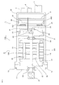
- FIG. 1 is an explanatory diagram of an electric drive device in an electric power steering device according to Embodiment 1 of the present invention.
- An electric drive device 100 shown in FIG. 1 has a structure in which a motor 5 and an ECU 4 according to Embodiment 1 of the present invention are integrally fixed.
- the permanent magnet type motor 5 will be described.
- the motor 5 includes a stator core 14 formed by laminating electromagnetic steel plates, an armature winding 15 housed in a later-described slot of the stator core 14, and a frame 16 that fixes the stator core 14.
- One end of the frame 16 in the axial direction is fixed to the motor housing 17 with bolts 18 and 19.
- the first bearing 20 is fixed to the motor housing 17.
- a second bearing 22 is fixed to the inner peripheral portion of the wall portion 21 formed at the other end portion of the frame 16 in the axial direction.
- the wall portion 21 is formed integrally with the frame 16, but may be formed separately.
- a rotor core 24 formed by laminating electromagnetic steel plates is fixed to the motor shaft 23 by press-fitting.
- the motor shaft 23 is rotatably supported by the motor housing 17 and the frame 16 via the first bearing 20 and the second bearing 22.
- a pulley 26 is press-fitted into one axial end of the motor shaft 23, that is, the output shaft side.
- the pulley 26 functions to transmit the driving force of the motor 5 to a belt (not shown) of the electric power steering device.
- a sensor permanent magnet 25 is fixed to the other axial end of the motor shaft 23.
- a permanent magnet 26 is fixed to the rotor core 24 described above. 1 shows an example in which the permanent magnet 26 is fixed to the surface of the rotor core 24, but a structure embedded in the rotor core 24 may be used. Details of these structures will be described later.
- the ECU 4 is provided with a first connector 3 that receives a signal from the torque sensor 2 described above, a second connector 6 that receives vehicle information such as vehicle speed, and a power supply connector 7 for supplying power. Further, the ECU 4 is provided with a first inverter circuit and a second inverter circuit which will be described later for driving the motor.
- the first inverter circuit has six first ching element groups 281 made of MOS-FETs or the like.
- the second inverter circuit has six second ching element groups 282 made of MOS-FETs or the like.
- Each of the switching elements in the first and second switching element groups 281 and 282 has, for example, a configuration in which a bare chip is mounted on a DBC (Direct Bonded Copper) substrate, or a configuration in which a bare chip is molded with a resin. Conceivable.
- Each switching element generates heat because a current for driving the motor flows.
- each switching element has a structure for releasing heat by contacting the heat sink 29 via an adhesive, an insulating sheet, or the like.
- the first and second inverter circuits are provided with a smoothing capacitor, a noise removing coil, a power supply relay, a bus bar for electrically connecting them, and the like. is doing.
- the bus bar is integrally formed with resin to form the intermediate member 30.
- a control board 31 is provided adjacent to the intermediate member 30. The control board 31 transmits a control signal to the first and second switching element groups 281 and 282 in order to appropriately drive the motor 5 based on the information received from the first and second connectors 3 and 6. .
- the control signal is transmitted by a connection member (not shown) that electrically connects the control board 31 and the switching elements of the first and second switching element groups 281 and 282.
- This connecting member is fixed to the semiconductor element or the control board 31 by wire bonding, press fitting, soldering or the like.
- the first and second inverter circuits constituted by these semiconductor elements and the control board 31 are covered with an ECU case 32.
- the ECU case 32 may be formed of resin, may be formed of a metal such as aluminum, or may be formed by combining a resin and a metal such as aluminum.
- the control board 31 is arranged along a plane orthogonal to the axial direction of the motor shaft 23 of the motor 5.
- the sensor unit 33 is disposed on the side surface of the heat sink 29 that faces the motor 5.
- the sensor unit 33 includes a magnetic sensor 34, a sensor substrate 35, a sensor connection member 36, and a sensor support member 37.
- the sensor substrate 35 on which the magnetic sensor 34 is mounted is fixed to the heat sink 29 with screws (not shown). Yes.
- the magnetic sensor 34 is disposed coaxially with the axis of the motor shaft 23 and is disposed at a position corresponding to the sensor permanent magnet 25, detects a magnetic field generated by the sensor permanent magnet 25, and detects the magnetic field.
- the rotation angle of the rotor of the motor 5 is detected by detecting the direction of.
- the sensor connection member 36 is supported by a sensor support member 37 and electrically connects the sensor substrate 35 of the sensor unit 33 and the control substrate 31. This connection may be press-fit or solder. Since the sensor connecting member 36 needs to pass through the heat sink 29 and the intermediate member 30, the heat sink 29 and the intermediate member 30 are provided with through holes (not shown) through which the sensor connecting member 36 passes. Further, although not shown, the intermediate member 30 is provided with a guide for positioning the sensor connection member 36.
- the heat sink 29 is provided with a recess 38, and the distance between the magnetic sensor 34 mounted on the sensor substrate 35 of the sensor unit 33 and the surface of the heat sink 29, that is, the bottom surface of the recess 38 is increased.
- the heat sink 29 is fixed to the frame 16 of the motor 5 by screws or shrink fitting. As described above, the heat sink 29 is fixed to the frame 16 of the motor 5, whereby the heat of the heat sink 29 can be transmitted to the frame 16.
- the ECU 4 supplies an appropriate drive current to the armature winding 15 of the motor 5 according to the rotation angle of the rotor of the motor 5 detected by the sensor unit 33.
- FIG. 1 shows an example in which the magnetic sensor 34 is mounted on a sensor board 35 different from the control board 31, the magnetic sensor 34 is mounted on the control board 31, and the sensor permanent magnet 25 is interposed via the heat sink 29. It is also possible to have a structure for detecting the magnetic flux leaking. Moreover, the structure which has arrange
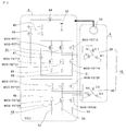
- FIG. 2 is an explanatory diagram of the circuit of the motor and ECU according to the first embodiment of the present invention.
- the armature winding 15 of the motor 5 includes a first armature winding constituted by a first U-phase winding U1, a first V-phase winding V1, and a first W-phase winding W1.
- the first and second armature windings 39 and 40 are shown as Y connections, but may be ⁇ connections.
- a direct current voltage is supplied to the ECU 4 from a power source 43 such as a battery via a noise removing coil 44.
- the ECU 4 includes two sets of inverter circuits, a first inverter circuit 41 and a second inverter circuit 42.
- the first inverter circuit 41 is supplied with a DC voltage from the power supply 43 via the coil 44 and the first power supply relay 45, and supplies a three-phase current to the first armature winding 39.
- the second inverter circuit 42 is supplied with a DC voltage from the power supply 43 via the coil 44 and the second power supply relay 46, and supplies a three-phase current to the second armature winding 40.
- the power source 43 is illustrated as if inside the ECU 4, but in reality, the power source 43 is supplied with power from a power source external to the ECU 4 such as an in-vehicle battery via a connector.
- the first and second power supply relays 45 and 46 are each composed of two MOS-FETs, and when a failure occurs, the MOS-FETs are opened so that an excessive current does not flow to the respective inverter circuits 41 and 42.
- the power supply 43, the coil 44, the first power supply relay 45, and the second power supply relay 46 are connected in this order, but the first power supply relay 45 and the power supply 43 are closer to the power supply 43 than the coil 44. Needless to say, the second power supply relay 46 may be connected. *
- the first smoothing capacitor 47 is connected between the input terminals of the first inverter circuit 41, and the second smoothing capacitor 48 is connected between the input terminals of the second inverter circuit 42.
- each of the first and second smoothing capacitors 47 and 48 is composed of one capacitor, but it goes without saying that a plurality of capacitors may be connected in parallel.
- the first and second inverter circuits 41 and 42 are each constituted by a three-phase bridge circuit using six MOS-FETs.
- the first inverter circuit 41 includes a first arm in which the MOS-FET 11 and the MOS-FET 12 are connected in series, a second arm in which the MOS-FET 13 and the MOS-FET 14 are connected in series, and the MOS-FET 15 A third arm connected in series with the MOS-FET 16 is provided, and these first to third arms are connected in parallel.
- One shunt resistor 49, 50, 51 is connected to the GND (ground potential) side of each of the MOS-FET 12, MOS-FET 14, and MOS-FET 16 located below the first to third arms, respectively. ing.
- the second inverter circuit 42 includes a first arm in which MOS-FET 21 and MOS-FET 22 are connected in series, a second arm in which MOS-FET 23 and MOS-FET 24 are connected in series, and a MOS A third arm having a FET 25 and a MOS FET 26 connected in series is provided, and these first to third arms are connected in parallel.
- One shunt resistor 52, 53, 54 is connected to the GND (ground potential) side of each of the MOS-FET 22, MOS-FET 24, and MOS-FET 26 located below the first to third arms, respectively. ing.
- Each of the shunt resistors 49 to 54 described above is used for detecting a current value.
- two shunts may be provided for each of the 1st and 2nd inverter circuits 41 and 42. Needless to say, such a configuration may be used because current detection is possible even with one shunt.
- the current is supplied from the first inverter circuit 41 to the motor 5 side from the series connection portion of the MOS-FET 11 and the MOS-FET 12 via a bus bar or the like.
- -It is supplied to the W1 phase of the first armature winding 39 of the motor 5 from a series connection with the FET 16 via a bus bar or the like.
- the current is supplied from the second inverter circuit 42 to the motor 5 side from the series connection portion of the MOS-FET 21 and the MOS-FET 22 via the bus bar or the like.
- FIG. 2 does not show a motor relay that electrically cuts off the motor 5 and the first and second inverter circuits 41 and 42 when some failure occurs in the ECU 4, the first and A case where the second armature windings 39 and 40 are provided at the neutral points N1 and N2 and a case where the second armature windings 39 and 40 are provided between the motor 5 and the first and second inverter circuits 41 and 42 are considered.
- the first and second inverter circuits 41, 42 are connected to each MOS-FET from a control circuit (not shown) according to the rotation angle of the rotor of the motor 5 detected by the rotation angle sensor 55 provided in the motor 5. These are switched by sending a signal to, and a desired three-phase current is supplied to the first and second armature windings 39 and 40.
- a magnetic sensor is used as the rotation angle sensor 50. Specifically, a combination of a permanent magnet and a GMR (Giant Magneto Resistive effect) sensor or AMR (Anisotropic Magneto Resistance) sensor, a resolver, or the like is used.
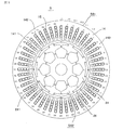
- FIG. 3 is a cross-sectional view of the permanent magnet type motor according to Embodiment 1 of the present invention.
- a stator 501 having an inner peripheral surface facing the outer peripheral surface of the rotor 502 through a gap is provided.
- the stator 501 includes the armature winding 15 including the first armature winding 39 and the second armature winding 40 described above, and the stator core 14.
- the stator core 14 includes an annular core back 140 made of a magnetic material such as an electromagnetic steel plate, and teeth 141 extending radially inward from the core back 140.
- the armature winding 15 is accommodated in a slot 142 provided between adjacent teeth 141.
- insulating paper or the like is inserted between the armature winding 15 and the stator core 14 to ensure electrical insulation.
- a total of 48 teeth 141 are provided, and therefore, the number of slots 142 is also 48.
- a coil of the armature winding 15 is accommodated in one slot 142.
- the first armature winding 39 is composed of three phases of the U1, V1, and W1 phases
- the second armature winding 40 is composed of three of the U2, V2, and W2 phases. It is composed of phases.
- the windings are arranged in the order of U1, U2, W1, W2, V1, V2 from the first slot (1), and U1, U2, and the like after the seventh slot (7). They are arranged in the order of W1, W2, V1, and V2, and are arranged in the same order up to the 48th slot (48). That is, the first armature winding 39 and the second armature winding 40 are disposed in the adjacent slots 142.
- the armature windings are arranged so that the current directions of the U1 phase of the first slot (1) and the U1 phase of the seventh slot (7) are opposite to each other.
- the distributed winding is wound from the first slot (1) to the seventh slot (7). Therefore, the armature winding is arranged across a total of six teeth. This corresponds to an electrical angle of 180 degrees, and the short winding coefficient is “1”. Therefore, the magnetic flux generated by the permanent magnet 26 can be used effectively, and a small high-torque motor can be obtained. Since it can be reduced, the cost can be reduced compared to a motor having a small winding coefficient.
- a rotor 502 having a permanent magnet 26 on the surface of the rotor core 24 is provided.
- Eight permanent magnets 26 are arranged at equal intervals in the circumferential direction of the rotor 502 and have a configuration of eight poles. The polarities of adjacent permanent magnets 26 are opposite to each other.
- the rotor core 24 is provided with eight protrusions 241, and a nonmagnetic gap for reducing leakage magnetic flux is provided between the protrusions 241 and the permanent magnet 26.
- This protrusion 241 has an effect of reducing the air gap between the stator 501 and the rotor 502 of the motor 5 and increases the inductance. As a result, the flux-weakening control is more likely to exert an effect, and there is an effect that the torque can be improved during high-speed rotation.
- the rotor core 24 is configured by stacking electromagnetic steel plates and the like, and the electromagnetic steel plates are connected to each other by a caulking portion 243.
- a motor shaft 23 passes through the central portion of the rotor core 24.
- the rotor core 24 is provided with eight holes 242. Providing these holes 242 has the effect of reducing the weight of the rotor core 24 and reducing the inertia.
- the first armature winding 39 and the second armature winding 40 are supplied with a three-phase alternating current whose phase is shifted by 30 degrees from each other, the first armature
- the phase of the electrical angle 6th order torque ripple generated by the magnetomotive force of the winding 39 and the electrical angle 6th order torque ripple generated by the magnetomotive force of the second armature winding 40 are reversed, and the electrical angle 6th order torque is reversed. Ripple is canceled.
- the rotor 502 includes a protrusion 241 formed on the rotor core 24, and the rotor is located closer to the stator 501 than an intermediate diameter between the maximum outer diameter and the minimum inner diameter of the permanent magnet 26.
- the height of the protrusion 241 is set so that the outer peripheral surface of the iron core 24, that is, the outer peripheral surface of the protrusion 241 is located.
- the reluctance torque can be obtained by utilizing the change in the magnetic resistance of the rotor core 24.
- the flux-weakening control is effective, and the torque at high speed is improved.
- FIG. 4 is an explanatory diagram of an equivalent circuit of the armature winding of the permanent magnet type motor according to the first embodiment of the present invention.
- vu represents each terminal voltage of the armature winding
- iu represents an armature current
- R represents a resistance
- ve represents an induced voltage
- lm represents a leakage inductance
- M represents a mutual inductance.
- “1” indicates the primary side
- the subscript “2” indicates the secondary side.
- N corresponds to the turn ratio in the transformer.
- lm and M are different from the values used in normal motor control, and indicate the inductance between multiple two phases arranged in parallel.
- FIG. 5 is an explanatory diagram of the q-axis circuit configuration of the permanent magnet type motor according to the first embodiment of the present invention, and shows an equivalent circuit of the q-axis when coordinate-converted to the rotor dq-axis in block diagram form. ing.
- vq1 and vq2 are q-axis voltages of the first armature winding and the second armature winding, respectively
- iq1 and iq2 are the first armature winding and the second armature winding, respectively.
- Lq1 and Lq2 are q-axis components of the self-inductance of the first armature winding and the second armature winding, respectively, and Ra1 and Ra2 are the first armature winding and the second electric machine, respectively.
- the resistance component of the child windings, Mq12 and Mq21 are q-axis components of the mutual inductance between the first armature winding and the second armature winding.
- s represents a differential operator of Laplace transform.
- vq12 and vq21 are disturbance voltages superimposed on the first armature winding and the second armature winding, respectively, due to the mutual inductance between the first armature winding and the second armature winding.
- FIG. 5 shows an equivalent circuit on the rotor q-axis, but the equivalent circuit on the rotor d-axis has the same configuration.
- the disturbance voltage is proportional to the differential value s, which is the control response frequency of the current, it increases as the current is controlled at high speed by motor control, making motor control that cancels torque ripple at a high response frequency difficult. .
- Embodiment 1 of the present invention the influence of the disturbance voltage in Embodiment 1 of the present invention will be considered.
- the disturbance voltage interacts with each other to cause disturbance to the current control system. Acts as values iq1 'and iq2'.
- the disturbance values iq1 ′ and iq2 ′ are expressed by the following equations (1) and (2) from the block diagram of the equivalent circuit of the q axis in FIG.
- iq1 and iq2 are q-axis currents of the first armature winding and the second armature winding, respectively, and Ra1 and Ra2 are the first armature winding and the second armature winding.
- Lq1 and Lq2 are q-axis components of the self-inductances of the first armature winding and the second armature winding, respectively, and Mq12 and Mq21 are the first armature windings.
- the q-axis component of the mutual inductance representing the interference between the second armature winding and the second armature winding.
- the Laplace transform differential operator s When the frequency of the current control is increased, the Laplace transform differential operator s is increased, and the disturbance value is substantially equal to the magnetic coupling Mq12 / Lq1 or the magnetic coupling Mq21 from the equations (1) and (2). It is clear that it depends on / Lq2.
- the disturbance value increases.
- the armature in the first embodiment may be considered as [Mq12 / Lq1 ⁇ Mq21 / Lq2] because the first armature winding and the second armature winding have a symmetrical structure. . Therefore, hereinafter, the magnetic coupling will be described as Mq12 / Lq1.
- the maximum outer diameter of the permanent magnet 26 is set.
- the peripheral surface of the rotor core 24 is provided on the side closer to the stator 501 than the intermediate diameter of the minimum inner diameter, the first armature winding 39 and the second electric machine are compared with the case where the peripheral surface is not so. There is a problem that the magnetic coupling Mq12 / Lq1 of the child winding 40 is increased, and the controllability of the motor is lowered.
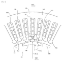
- FIG. 6 is an enlarged cross-sectional view showing the stator core of the permanent magnet type motor according to Embodiment 1 of the present invention.
- the stator 501 includes a stator core 14 having a core back 140, a tooth 141, and a slot 142, and an armature winding 15 housed in the slot 142. Insulating paper or the like is provided between the armature winding 15 and the stator core 14 in order to ensure electrical insulation, but is omitted in FIG.
- a flange 56 is provided at the tip of the tooth 141.
- the width of the thinnest portion of the tooth 141 is indicated by w
- the distance between the adjacent flanges 56 is indicated by a
- the radial height of the surface of the stator core 24 facing the adjacent flanges 56 is indicated by h.
- the curved surface portion R1 is provided on the inner side in the radial direction of the surface where the adjacent flange portions 56 face each other.
- the height h is the height of the region excluding the curved surface portion R1.
- the curved surface portion R1 is set to about 0.2 [mm] to 0.4 [mm].
- the rotor 502 has a configuration in which the rotor core 24 and the permanent magnet 26 are arranged on the surface thereof, and protrusions 241 are provided on both sides of the permanent magnet 26.
- the protruding portion 241 protrudes toward the inner peripheral surface side of the stator 501, but its height is closer to the stator 501 than the intermediate diameter between the maximum outer diameter Rout and the minimum inner diameter Rin of the permanent magnet 26. Protrudes up to.
- the entire outer peripheral surface of the rotor 502 may be covered with a nonmagnetic metal tube such as SUS or aluminum, but is omitted in FIG.
- the magnetic air gap length between the outer peripheral surface of the rotor 502 and the inner peripheral surface of the stator 501 is g.
- the magnetic air gap length g includes the thickness of the metal tube.
- the radial height h and the magnetic air gap length g of the surface of the stator core 14 where the adjacent flanges 56 oppose each other have a relationship of [1 ⁇ h / g ⁇ 2]. Further, the distance a in the circumferential direction and the magnetic air gap length g between the surfaces of the adjacent flange portions 56 of the stator core facing each other satisfy the relationship [a / g ⁇ 0.2].
- FIG. 7 is an explanatory diagram for explaining the magnetic coupling of the first armature winding and the second armature winding of the permanent magnet type motor according to the first embodiment of the present invention.
- FIG. 7A shows the relationship between the radial height h, the magnetic air gap length g, the motor torque, and the magnetic coupling between the surfaces of the adjacent flanges 56 facing each other, and the horizontal axis is h / g.
- the vertical axis represents torque and magnetic coupling.
- the magnetic coupling is shown as Mq12 / Lq1 [%].
- the leakage magnetic flux to the adjacent teeth 141 can be reduced, so that the torque reduction is only 0.5 [%] or less.
- the magnetic coupling Mq12 / Lq1 becomes a value of 69 [%] or less, and the frequency response of the control can be enhanced, and the motor control of the electric power steering device (EPS) is achieved. There is an effect that a frequency response necessary for the above can be obtained.
- FIG. 7B shows the magnetic air between the rotor 502 and the stator 501, and the distance a in the circumferential direction of the surface of the teeth 141 of the stator core 14 where the adjacent flanges 56 face each other. It is the figure which showed the relationship between the gap length g and a magnetic coupling.
- the horizontal axis represents a / g
- the vertical axis represents the magnetic coupling Mq12 / Lq1.
- FIG. 8 is an explanatory diagram of NT (speed-torque) characteristics of the permanent magnet type motor according to Embodiment 1 of the present invention, showing the relationship between the motor rotation speed N and torque T, and the horizontal axis represents the motor rotation.
- Two types of motors (1) and motors (2) having the same rated torque are shown in comparison.
- the subscript “1” indicates the motor (1), and the subscript “2” indicates the motor (2).
- a curve C1 is a characteristic of the motor (1), and the rotor core 24 is provided on the side closer to the stator 501 than the intermediate diameter between the maximum outer diameter and the minimum inner diameter of the permanent magnet 26.
- a curve C2 is a characteristic of the motor (2).
- FIG. 9 is an enlarged cross-sectional view showing a stator core of Modification 1 of the permanent magnet type motor according to Embodiment 1 of the present invention.
- the radial height h and the magnetic air gap length g of the surface where the adjacent flange portions 56 of the teeth 141 of the stator core 14 face each other are set to [1 ⁇ h / g. ⁇ 2] is established.
- the height h is the height of the region excluding the curved surface portions R1 and R2.
- the curved surface portions R1 and R2 are set to about 0.2 [mm] to 0.4 [mm]. It goes without saying that the effects described in the explanation of FIG. 6 can be obtained by adopting such a configuration, but further, by providing the curved surface portions R1 and R2, the magnetism between the curved surface portions R1 and R2 of the adjacent flange portions is provided. There is an effect that resistance increases and magnetic coupling can be reduced. Furthermore, the provision of the curved surface portions R1 and R2 on both the inner side and the outer side in the radial direction has an effect of facilitating the punching of the electromagnetic steel sheet with the mold and extending the life of the mold.
- FIG. 10 is an enlarged cross-sectional view showing the stator core in Modification 2 of the permanent magnet type motor according to Embodiment 1 of the present invention.
- the width of the tooth 141 at the portion where the tooth 141 is thinnest radially outside the flange portion 56 is w
- the maximum outer diameter of the rotor core 24 is Rout
- the number of slots is Ns
- the following equation (3) is satisfied. 0.4 ⁇ 2 ⁇ (Rout + g + h) / Ns ⁇ w ⁇ 0.5 ⁇ 2 ⁇ (Rout + g + h) / Ns Equation (3)
- the air gap magnetic flux density of a motor using a neodymium iron boron rare earth magnet as the permanent magnet 26 is 0.8 T
- the maximum value of the magnetic flux density at the portion where the tooth 141 is the thinnest is about 1.6T to 2.0T.
- the width in the circumferential direction of the slot 142 at the portion where the teeth 141 are the thinnest is S1, w ⁇ S1.
- the slot width is equal to or greater than the teeth width, and a large slot cross-sectional area can be secured.
- the self-inductance is increased by relaxing the magnetic saturation, the effect that Mq12 / Lq1 is reduced and the controllability is improved can be obtained.
- the circumferential width of the slot increases as it goes radially outward, and the slot width is the maximum value S2 in the vicinity of the core back.
- the slot cross-sectional area can be ensured larger than the configuration in which the width of the slot 142 is constant, the cross-sectional area of the armature winding 15 can be secured large, and the copper loss can be reduced and the motor output can be improved.
- the permanent magnet type motor of the first embodiment described above is mounted on an electric power steering device, it is possible to significantly reduce torque ripple sixth order.
- the magnetic coupling increases at the same time as the output of the motor increases, and the controllability of the motor decreases.
- the electric power steering device can be applied to a large vehicle. This has the effect of reducing fuel consumption.
- such a motor is suitable for an electric power steering apparatus arranged in a direction parallel to the moving direction of a rack shaft used for a high output because it has low vibration and low noise even at high output.
- FIG. 11 is a cross-sectional view of a permanent magnet type motor according to Embodiment 2 of the present invention.
- the stator 501 has the same structure as that of the first embodiment shown in FIG.
- the rotor 502 has a flat permanent magnet 26 embedded in a permanent magnet hole 57 formed in the rotor core 24.
- Eight permanent magnet hole portions 57 are formed in the vicinity of the outer peripheral surface of the rotor core 24 at equal intervals in the circumferential direction, and one permanent magnet 26 is embedded in each permanent magnet hole portion 57.
- the permanent magnets 26 adjacent to each other in the circumferential direction are arranged so that the polarities are in opposite directions.
- a slit 58 is provided in the rotor core 24 closer to the stator 501 than the permanent magnet 26.
- the slit 58 is filled with a nonmagnetic material such as air or resin.
- the slit 58 is disposed obliquely so that the magnetic flux is directed toward the magnetic pole center. Thereby, the torque of the motor is increased, and a small and high output motor can be obtained.
- the rotor core 24 is provided with a hole 242. By providing the hole 242, weight reduction and inertia can be reduced.
- the rotor core 24 is configured by laminating electromagnetic steel plates and the like, and the electromagnetic steel plates are connected to each other by a crimping portion 243.
- a motor shaft 23 passes through the center of the rotor core 24.
- the rotor has the iron core 24 near the stator core 14, so that the magnetic resistance between the stator core 14 and the rotor core 24 is reduced, and as a result, the first Although the magnetic coupling between the armature winding 39 and the second armature winding 40 tends to be large, the structure as described in the second embodiment reduces the magnetic coupling. The effect that controllability is improved is obtained. Furthermore, since the reluctance torque can be used, the usage amount of the permanent magnet 26 can be reduced. In addition, since the inductance is large, the effect of flux-weakening control can be exhibited, so that the effect of improving the torque during high-speed rotation can be obtained.
- FIG. 12 is a cross-sectional view of a permanent magnet type motor according to Embodiment 3 of the present invention, and is referred to as a spoke type IPM.
- the stator 501 has the same structure as that of the first embodiment shown in FIG.
- the stator 501 has the same structure as that of the first embodiment shown in FIG.
- the rotor 502 has a structure different from that in the case of FIGS.
- the rotor 502 includes a motor shaft 23 serving as a rotation shaft, and a rotor core 24 provided outside the motor shaft 23.
- the permanent magnet 26 has a shape in which the length in the radial direction is longer than the length in the circumferential direction, and eight permanent magnets 26 are arranged at equal intervals in the circumferential direction.
- the permanent magnet 26 is magnetized in such a direction that N and S shown in FIG. 12 become N and S poles, respectively. That is, the facing surfaces of the adjacent permanent magnets 26 are magnetized so as to have the same pole.
- N and S shown in FIG. 12 become N and S poles, respectively. That is, the facing surfaces of the adjacent permanent magnets 26 are magnetized so as to have the same pole.
- the surface opposite to the inner peripheral surface of the stator 501 of the rotor core 24, that is, the outer peripheral surface is formed in a curved surface shape.
- the shape of the curved surface is a convex curved surface 61 so that the gap length with the stator 501 is shortened at an intermediate point between adjacent permanent magnets 20.
- a non-magnetic portion 59 is provided so as to contact the inner surface of the permanent magnet 26.
- the nonmagnetic portion 59 may be air, may be filled with resin, or a nonmagnetic metal such as stainless steel or aluminum may be inserted.
- a connecting portion 60 is provided between the rotor core 24 between the adjacent permanent magnets 26 and the rotor core 24 provided so as to surround the outer periphery of the motor shaft 23.
- the connecting portion 60 has a function of mechanically connecting the rotor core 24, the motor shaft 23 and the person.
- a hole 242 is provided in the rotor core 24 between the adjacent permanent magnets 26. By making the hole 242 air, the effect of reducing the weight and inertia of the rotor 502 can be obtained.
- the rotor core 24 is present near the stator core 14, so that the magnetic resistance between the stator core 14 and the rotor core 24 is reduced, resulting in the first armature.
- the configuration of the third embodiment allows the first armature winding 39 and the second armature.
- the magnetic coupling of the winding 40 is reduced, and the controllability is improved.
- the usage amount of the permanent magnet 26 can be reduced.
- the inductance is greatly reduced and the effect of magnetic flux control can be exhibited, the effect of improving the torque during high-speed rotation can also be obtained.
- FIG. 13 is a cross-sectional view of a permanent magnet type motor according to Embodiment 4 of the present invention, which is a so-called “consequent pole type” permanent magnet type motor.
- the stator 501 has the same structure as that of the first embodiment shown in FIG.
- the rotor 502 has a structure different from those shown in FIGS.
- the rotor 502 includes a motor shaft 23 serving as a rotation shaft, and a rotor core 24 provided outside the motor shaft 23.
- Permanent magnets 26 are arranged on the surface of the rotor core 24, and four permanent magnets are arranged at equal intervals in the circumferential direction.
- the permanent magnet 26 is magnetized so that the radially outer side is N-pole and the radially inner side is S-pole, and the salient pole part 62 of the rotor core 24 between the adjacent permanent magnets 26. Functions virtually as the S pole. That is, it operates as a motor equivalent to 8 poles.
- This type of motor is a motor generally called a consequent pole type.
- the holes 242 and the caulking portions 243 of the rotor core 24 are as described in FIGS.
- FIG. 13 shows an example in which the permanent magnet 26 is disposed on the surface of the rotor core 24.
- the permanent magnet 26 is a continuous pole type having a structure in which the permanent magnet 26 is embedded in the rotor core 24. Needless to say, the same effect can be obtained.
- the embodiments can be freely combined, and the embodiments can be appropriately modified or omitted.
- a rotor including a rotor core fixed to the motor shaft, and a permanent magnet fixed to the rotor core;
- a stator having a stator core having a plurality of slots for accommodating armature windings and a plurality of teeth, and having an inner peripheral surface facing the outer peripheral surface of the rotor via a magnetic air gap;
- a permanent magnet motor with The armature winding is composed of a plurality of sets of multiphase windings, The plurality of sets of multiphase windings are fed from individual inverters for each set, A part of the rotor core is present on a side closer to the stator than an intermediate diameter between the maximum outer diameter and the minimum inner diameter of the permanent magnet,
- Each of the plurality of teeth includes a buttocks, The flange portion is opposed to the side surface portion of the flange portion provided on the teeth adjacent to the side surface portion protruding in the circumferential direction of the stator core.
- the armature winding is composed of two sets of three-phase armature windings including a first armature winding and a second armature winding,
- the first armature winding is supplied with current from a first inverter circuit
- the second armature winding is supplied with current from a second inverter circuit
- the first armature winding includes a U1-phase winding, a V1-phase winding, and a W1-phase winding
- the second armature winding includes a U2-phase winding, a V2-phase winding, and a W2-phase winding
- the U1-phase winding and the U2-phase winding are housed in the slots adjacent to each other
- the V1-phase winding and the V2-phase winding are housed in the slots adjacent to each other
- the W1-phase winding and the W2-phase winding are housed in the slots adjacent to each other
- the respective currents flowing through the first armature winding and the second armature winding
- the side surface portion of the flange portion includes a curved surface portion in any one of a portion located inside the radial direction of the stator and a portion located outside the radial direction.
- the provision of the curved surface portion has the effect of increasing the magnetic resistance between the R portions of the adjacent flange portions and reducing the magnetic coupling.
- the side surface portion of the flange includes a curved surface portion in both a portion located on the inner side in the radial direction of the stator and a portion located on the outer side in the radial direction.
- the provision of the curved surface portion has the effect of increasing the magnetic resistance between the curved surface portions of the adjacent flanges and reducing the magnetic coupling. Furthermore, by providing curved portions on both the inside and outside in the radial direction, there is an effect that the die can be easily punched and the life of the die is extended.
- the provision of the curved surface portion has the effect of increasing the magnetic resistance between the curved surface portions of the adjacent flanges and reducing the magnetic coupling. Furthermore, by providing curved portions on both the inside and outside in the radial direction, there is an effect that the die can be easily punched and the life of the die is extended. In addition, since the surfaces facing the flanges are parallel to each other, the magnetic resistance at this portion is uniform. Since the magnetic flux leaks to the adjacent teeth through this surface, Mq12 / Lq1 can be reduced, and as a result, the controllability of the motor is improved.
- the circumferential width of the slot corresponding to the portion of the teeth that is present on the outer side of the stator in the radial direction from the flange and has the smallest circumferential width of the stator is S1
- the slot width S1 is: 0.5 ⁇ 2 ⁇ (Rout + g + h) / Ns ⁇ S1 ⁇ 0.6 ⁇ 2 ⁇ (Rout + g + h) / Ns
- the circumferential width of the slot gradually increases as it is located on the outer side of the stator in the radial direction, and becomes the maximum at or near the bottom of the slot.
- the slot cross-sectional area can be secured large, the cross-sectional area of the armature winding can be secured large, and the copper loss can be reduced and the output of the motor can be improved.
- the circumferential width of the slots is large in the vicinity of the core back, there is an effect that the magnetic resistance between the slots is increased and the leakage magnetic flux is reduced, and the motor torque can be improved and the amount of permanent magnets can be reduced. There is.
- the permanent magnet is disposed on a surface of the rotor core facing the stator core,
- the rotor core includes a protrusion provided at a portion where the permanent magnet is not disposed, A gap is provided between the protrusion and the permanent magnet.
- the protrusion has the effect of reducing the air gap of the motor, and the inductance increases.
- the flux-weakening control can easily exert an effect, and there is an effect that the torque can be improved during high-speed rotation.
- the configuration of the present invention has the effect that the magnetic coupling can be reduced. is there.
- the permanent magnet is installed in a hole provided in the rotor core.
- the permanent magnet type motor according to any one of (1) to (7), wherein:
- the weakening magnetic flux control can be effectively used by increasing the inductance, the effect of improving the torque at high speed rotation can be obtained. Since a protective tube for preventing the permanent magnets from scattering is unnecessary, there is an effect that the cost can be reduced. On the other hand, since the magnetic gap between the rotor core and the stator core is small, there is a problem that the magnetic coupling between different sets of armature windings increases. There is an effect that the ring can be reduced.
- the permanent magnet is formed such that a radial length of the rotor is larger than a circumferential length,
- the magnetization direction of the permanent magnet is such that the facing surfaces of adjacent permanent magnets have the same polarity as each other,
- the rotor core is interposed between the adjacent permanent magnets,
- the rotor iron core includes a non-magnetic portion provided at a position having a curved surface portion on a surface facing the stator iron core, and in contact with an end surface on the inner diameter side of the permanent magnet,
- the curved surface portion is formed in a convex shape so that the length of the gap is shorter than the other portion in an intermediate portion between the adjacent permanent magnets.
- the torque can be improved and the motor can be downsized by concentrating the magnetic flux of the permanent magnet and increasing the magnetic flux density.
- a convex curved surface can be formed to reduce torque ripple and cogging torque.
- a device, The axial direction of the permanent magnet motor is arranged in parallel with the direction in which the rack shaft that drives the steering wheel of the vehicle extends.
- the electric power steering device described in (11) it is possible to significantly reduce torque ripple sixth order.
- the magnetic coupling increases at the same time as the output of the motor increases, and the controllability of the motor decreases.
- the electric power steering device can be applied to a large vehicle. This has the effect of reducing fuel consumption.
- the present invention can be used in the field of motors having permanent magnets and electric power steering using the motors, and in the field of vehicles such as automobiles.
Landscapes
- Engineering & Computer Science (AREA)
- Power Engineering (AREA)
- Microelectronics & Electronic Packaging (AREA)
- Permanent Magnet Type Synchronous Machine (AREA)
- Power Steering Mechanism (AREA)
- Iron Core Of Rotating Electric Machines (AREA)
- Permanent Field Magnets Of Synchronous Machinery (AREA)
Abstract
Description
モータシャフトに固定された回転子鉄心と、前記回転子鉄心に固定された永久磁石とを備えた回転子と、
電機子巻線を収納する複数のスロットと複数のティースを有し内周面が磁気的エアギャップを介して前記回転子の外周面と対向する固定子鉄心を備えた固定子と、
を備えた永久磁石型モータであって、
前記電機子巻線は、複数組の多相巻線により構成され、
前記複数組の多相巻線は、夫々の組毎に個別のインバータから給電され、
前記回転子鉄心の一部は、前記永久磁石の最大外径と最小内径との中間の直径よりも前記固定子に近い側に存在し、
前記複数のティースは、夫々鍔部を夫々備え、
前記鍔部は、側面部が前記固定子鉄心の周方向に突出して隣接する前記ティースに設けられた鍔部の側面部と対向し、
前記鍔部の側面部に於ける前記固定子鉄心の径方向の高さをh、前記磁気的エアギャップの長さをgとしたとき、
1≦h/g≦2
なる関係が成立し、且つ、
隣り合う前記鍔部が対向する面の周方向の距離をaとしたとき、
a/g≧0.2
なる関係を満たす、
ことを特徴とするものである。
前記永久磁石型モータは、その軸方向が車両の操舵輪を駆動するラック軸の延びる方向と平行に配置されている、
ことを特徴とするものである。
制御性が向上すると共に、装置をコンパクト化することができる効果を備えるものである。
図14は、この発明の実施の形態1による永久磁石型モータを備えた電動パワーステアリング装置の説明図である。図14に於いて、自動車等の車両の運転者は、ステアリングホイール(図示せず)を操舵し、運転者による操舵トルクがステアリングシャフト(図示せず)を介して操舵シャフト1に伝達される。このときトルクセンサ2が検出した操舵トルクは、電気信号に変換されケーブル(図示せず)を通じてコネクタ3を介してECU(Electronic Control Unit)4に伝達される。ECU4は、制御基板と、後述するこの発明の実施の形態1による永久磁石型モータ5を駆動するためのインバータ回路(図示せず)を備えている。尚、以下の説明に於いて、永久磁石型モータ5を、単に、モータと称することもある。

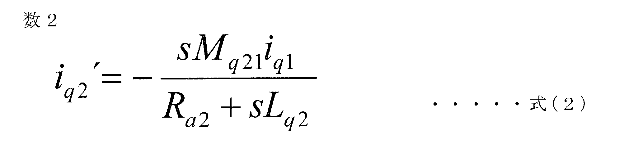
図9は、この発明の実施の形態1による永久磁石型モータの変形例1の固定子鉄心を拡大して示す横断面図である。図9に示す永久磁石型モータでは、固定子鉄心14のティース141に於ける隣り合う鍔部56が対向する面の径方向高さhと磁気的なエアギャップ長gに[1≦h/g≦2]なる関係が成り立つ構成としている。
図10は、この発明の実施の形態1による永久磁石型モータの変形例2に於ける、固定子鉄心を拡大して示す横断面図である。図8に示す変形例2では、鍔部56より径方向外側でティース141が最も細くなる部分に於けるティース141の幅をw、回転子鉄心24の最大外径をRout、スロット数をNs、としたとき、下記の式(3)が成り立つ構成とした。
0.4×2π(Rout+g+h)/Ns
≦w≦0.5×2π(Rout+g+h)/Ns・・・・・式(3)
0.5×2π(Rout+g+h)/Ns
≦S1≦0.6×2π(Rout+g+h)/Ns ・・・・・式(4)
と書くことができる。この構成であれば、前述のようにティース141が最も細くなる部分の磁束密度の最大値がおおよそ1.6T~2.0T程度になる。これにより、ティース141の最も細くなる部分の磁気飽和を緩和できるため、定格トルクが向上する。
実施の形態1では、回転子鉄心の表面に永久磁石を配置した構造について述べたが、実施の形態2では永久磁石を回転子鉄心の中に埋め込んだ永久磁石型モータ(IPM)としたものである。図11は、この発明の実施の形態2による永久磁石型モータの横断面図である。図11に於いて、固定子501は図3の実施の形態1の場合と同じ構造である。
図12は、この発明の実施の形態3による永久磁石型モータの横断面図であって、スポーク(Spoke)型IPMと称する。図12に於いて、固定子501は、図3の実施の形態1の場合と同じ構造である。図12に於いて、固定子501は図3の実施の形態1の場合と同じ構造である。回転子502は、前述の図3、図11の場合とは異なる構造である。回転子502は、回転軸となるモータシャフト23と、このモータシャフト23の外側に回転子鉄心24が設けられている。
図13は、この発明の実施の形態4による永久磁石型モータの横断面図であって、所謂、コンシクエントポール(consequent pole)型と称される永久磁石型モータである。図13に於いて、固定子501は図3の実施の形態1の場合と同じ構造である。回転子502は、図3、図11、図12とは異なる構造である。回転子502は、回転軸となるモータシャフト23と、このモータシャフト23の外側に回転子鉄心24が設けられている。回転子鉄心24の表面に永久磁石26が配置されており、周方向に等間隔に4個配置されている。
電機子巻線を収納する複数のスロットと複数のティースを有し内周面が磁気的エアギャップを介して前記回転子の外周面と対向する固定子鉄心を備えた固定子と、
を備えた永久磁石型モータであって、
前記電機子巻線は、複数組の多相巻線により構成され、
前記複数組の多相巻線は、夫々の組毎に個別のインバータから給電され、
前記回転子鉄心の一部は、前記永久磁石の最大外径と最小内径との中間の直径よりも前記固定子に近い側に存在し、
前記複数のティースは、夫々鍔部を夫々備え、
前記鍔部は、側面部が前記固定子鉄心の周方向に突出して隣接する前記ティースに設けられた鍔部の側面部と対向し、
前記鍔部の側面部に於ける前記固定子鉄心の径方向の高さをh、前記磁気的エアギャップの長さをgとしたとき、
1≦h/g≦2
なる関係が成立し、且つ、
隣り合う前記鍔部が対向する面の周方向の距離をaとしたとき、
a/g≧0.2
なる関係を満たす、
ことを特徴とする永久磁石型モータ。
前記第1の電機子巻線は、第1のインバータ回路から電流が供給され、
前記第2の電機子巻線は、第2のインバータ回路から電流が供給され、
前記第1の電機子巻線は、U1相巻線と、V1相巻線と、W1相巻線と、を備え、
前記第2の電機子巻線は、U2相巻線と、V2相巻線と、W2相巻線と、を備え、
前記U1相巻線と前記U2相巻線は、互いに隣り合う前記スロットに収納され、
前記V1相巻線と前記V2相巻線は、互いに隣り合う前記スロットに収納され、
前記W1相巻線と前記W2相巻線は、互いに隣り合う前記スロットに収納さ、
前記第1の電機子巻線と前記第2の電機子巻線とに流れる夫々の電流は、互いに電気角20度以上40度以下の位相差を備える、
ことを特徴とする前記(1)に記載の永久磁石型モータ。
ことを特徴とする前記(1)又は(2)に記載の永久磁石型モータ。
ことを特徴とする前記(1)又は(2)に記載の永久磁石型モータ。
ことを特徴とする前記(4)に記載の永久磁石型モータ。
0.4×2π(Rout+g+h)/Ns
≦w≦0.5×2π(Rout+g+h)/Ns
の関係を満たす、
ことを特徴とする前記(1)乃至(5)のうちの何れかに記載の永久磁石型モータ。
0.5×2π(Rout+g+h)/Ns
≦S1≦0.6×2π(Rout+g+h)/Ns
の関係を満たし、且つ、
前記スロットの周方向の幅は、前記固定子の径方向の外側に位置するに伴って漸次大きくなり、前記スロットの底部若しくはその近傍に於いて最大となる、
ことを特徴とする前記(1)乃至(5)のうちの何れかに記載の永久磁石型モータ。
前記回転子鉄心は、前記永久磁石が配置されていない部位に設けられた突起部を備え、
前記突起部と前記永久磁石との間には空隙が設けられている、
ことを特徴とする前記(1)乃至(7)のうちの何れかに記載の永久磁石型モータ。
ことを特徴とする前記(1)乃至(7)のうちの何れか一項に記載の永久磁石型モータ。
前記永久磁石の着磁方向は、隣り合う永久磁石の向かい合う面が互いに同一極となるような向きであり、
隣り合う前記永久磁石の間には前記回転子鉄心が介在し、
前記回転子鉄心は、前記固定子鉄心に対向する面に曲面部を有し、且つ前記永久磁石の内径側の端面に接する位置に設けられた非磁性部を備え、
前記曲面部は、隣り合う前記永久磁石と間の中間部に於いて前記空隙の長が他の部分より短くなるように凸形状に形成されている、
ことを特徴とする前記(1)乃至(7)のうちの何れかに記載の永久磁石型モータ。
前記永久磁石型モータは、その軸方向が車両の操舵輪を駆動するラック軸の延びる方向と平行に配置されている、
ことを特徴とする電動パワーステアリング装置。
3 第1のコネクタ、4 ECU、5 永久磁石型モータ、
6 第2のコネクタ、7 電源コネクタ、8 ギヤボックス、
9 ハウジング、10、11 タイロッド、12、13 ラックブーツ、
14 固定子鉄心、15 電機子巻線、16 フレーム、
17 モータハウジング、18、19 ボルト、20 第1の軸受、
21 壁部、22 第2の軸受、23 モータシャフト、
24 回転子鉄心、242 穴部、243 カシメ部、
25 センサ用永久磁石、26 永久磁石、27 プーリー、
281 第1のスイッチング素子群、282 第2のスイッチング素子群、
29 ヒートシンク、30 中間部材、31 制御基板、
32 ECUケース、33 センサ部、34 磁気センサ、
35 センサ基板、36 センサ接続部材、37 センサ支持部材、
38 凹部、39 第1の電機子巻線、40 第2の電機子巻線、
41 第1のインバータ回路、42 第2のインバータ回路、43 電源、
44 コイル、45 第1の電源リレー、46 第2の電源リレー、
47 第1の平滑コンデンサ、48 第2の平滑コンデンサ、
49、50、51、52、53、54 シャント抵抗、
55 回転角度センサ、501 固定子、502 回転子、
241 突起部、140 コアバック、141 ティース、
142 スロット、56 鍔部、57 永久磁石用穴部、58 スリット、
60 連結部、61 凸形状曲面、62 突極部。
Claims (11)
- モータシャフトに固定された回転子鉄心と、前記回転子鉄心に固定された永久磁石とを備えた回転子と、
電機子巻線を収納する複数のスロットと複数のティースを有し内周面が磁気的エアギャップを介して前記回転子の外周面と対向する固定子鉄心を備えた固定子と、
を備えた永久磁石型モータであって、
前記電機子巻線は、複数組の多相巻線により構成され、
前記複数組の多相巻線は、夫々の組毎に個別のインバータから給電され、
前記回転子鉄心の一部は、前記永久磁石の最大外径と最小内径との中間の直径よりも前記固定子に近い側に存在し、
前記複数のティースは、夫々鍔部を夫々備え、
前記鍔部は、側面部が前記固定子鉄心の周方向に突出して隣接する前記ティースに設けられた鍔部の側面部と対向し、
前記鍔部の側面部に於ける前記固定子鉄心の径方向の高さをh、前記磁気的エアギャップの長さをgとしたとき、
1≦h/g≦2
なる関係が成立し、且つ、
隣り合う前記鍔部が対向する面の周方向の距離をaとしたとき、
a/g≧0.2
なる関係を満たす、
ことを特徴とする永久磁石型モータ。 - 前記電機子巻線は、第1の電機子巻線と第2の電機子巻線からなる2組の3相電機子巻線により構成され、
前記第1の電機子巻線は、第1のインバータ回路から電流が供給され、
前記第2の電機子巻線は、第2のインバータ回路から電流が供給され、
前記第1の電機子巻線は、U1相巻線と、V1相巻線と、W1相巻線と、を備え、
前記第2の電機子巻線は、U2相巻線と、V2相巻線と、W2相巻線と、を備え、
前記U1相巻線と前記U2相巻線は、互いに隣り合う前記スロットに収納され、
前記V1相巻線と前記V2相巻線は、互いに隣り合う前記スロットに収納され、
前記W1相巻線と前記W2相巻線は、互いに隣り合う前記スロットに収納さ、
前記第1の電機子巻線と前記第2の電機子巻線とに流れる夫々の電流は、互いに電気角20度以上40度以下の位相差を備える、
ことを特徴とする請求項1に記載の永久磁石型モータ。 - 前記鍔部の側面部は、前記固定子の径方向の内側に位置する部位と径方向の外側に位置する部位とのうちの何れか一方に曲面部を備えている、
ことを特徴とする請求項1又は2に記載の永久磁石型モータ。 - 前記鍔部の側面部は、前記固定子の径方向の内側に位置する部位と径方向の外側に位置する部位の双方に曲面部を備えている、
ことを特徴とする請求項1又は2に記載の永久磁石型モータ。 - 隣接するティースに夫々設けられ互いに対向する前記鍔部の前記側面部は、互いに平行となるように構成されている、
ことを特徴とする請求項1又は2に記載の永久磁石型モータ。 - 前記鍔部より前記固定子の径方向の外側に存在し且つ前記固定子の周方向の幅が最も小さくなる前記ティースの部位の幅をw、前記回転子鉄心の最大外径をRout、スロット数をNsとしたとき、前記ティースの幅wは、
0.4×2π(Rout+g+h)/Ns
≦w≦0.5×2π(Rout+g+h)/Ns
の関係を満たす、
ことを特徴とする請求項1乃至5のうちの何れか一項に記載の永久磁石型モータ。 - 前記鍔部より前記固定子の径方向の外側に存在し且つ前記固定子の周方向の幅が最も小さくなる前記ティースの部位に対応する前記スロットの前記周方向の幅をS1、前記回転子鉄心の最大外径をRout、スロット数をNsとしたとき、前記スロットの幅S1は、
0.5×2π(Rout+g+h)/Ns
≦S1≦0.6×2π(Rout+g+h)/Ns
の関係を満たし、且つ、
前記スロットの周方向の幅は、前記固定子の径方向の外側に位置するに伴って漸次大きくなり、前記スロットの底部若しくはその近傍に於いて最大となる、
ことを特徴とする請求項1乃至5のうちの何れか一項に記載の永久磁石型モータ。 - 前記永久磁石は、前記固定子鉄心に対向する前記回転子鉄心の表面に配置されており、
前記回転子鉄心は、前記永久磁石が配置されていない部位に設けられた突起部を備え、
前記突起部と前記永久磁石との間には空隙が設けられている、
ことを特徴とする請求項1乃至7のうちの何れか一項に記載の永久磁石型モータ。 - 前記永久磁石は、前記回転子鉄心に設けられた穴部に設置されている、
ことを特徴とする請求項1乃至7のうちの何れか一項に記載の永久磁石型モータ。 - 前記永久磁石は、前記回転子の径方向の長さが周方向の長さに比べて大きく形成されており、
前記永久磁石の着磁方向は、隣り合う永久磁石の向かい合う面が互いに同一極となるような向きであり、
隣り合う前記永久磁石の間には前記回転子鉄心が介在し、
前記回転子鉄心は、前記固定子鉄心に対向する面に曲面部を有し、且つ前記永久磁石の内径側の端面に接する位置に設けられた非磁性部を備え、
前記曲面部は、隣り合う前記永久磁石との間の中間部に於いて前記空隙の長が他の部分より短くなるように凸形状に形成されている、
ことを特徴とする請求項1乃至7のうちの何れか一項に記載の永久磁石型モータ。 - 請求項1乃至10のうちの何れか一項に記載の永久磁石型モータが搭載され、前記永久磁石型モータにより運転者の操舵をアシストするトルクを発生させるようにした電動パワーステアリング装置であって、
前記永久磁石型モータは、その軸方向が車両の操舵輪を駆動するラック軸の延びる方向と平行に配置されている、
ことを特徴とする電動パワーステアリング装置。
Priority Applications (6)
| Application Number | Priority Date | Filing Date | Title |
|---|---|---|---|
| PCT/JP2013/069737 WO2015011747A1 (ja) | 2013-07-22 | 2013-07-22 | 永久磁石型モータ、及び電動パワーステアリング装置 |
| EP13889887.9A EP3026799B1 (en) | 2013-07-22 | 2013-07-22 | Permanent magnet motor and electric power steering device |
| US14/783,104 US10320254B2 (en) | 2013-07-22 | 2013-07-22 | Permanent magnet motor and electric power steering apparatus |
| JP2015528018A JP6091619B2 (ja) | 2013-07-22 | 2013-07-22 | 永久磁石型モータ、及び電動パワーステアリング装置 |
| CN201380078438.5A CN105432005A (zh) | 2013-07-22 | 2013-07-22 | 永磁体型电动机及电动助力转向装置 |
| CN201911141685.0A CN111342574A (zh) | 2013-07-22 | 2013-07-22 | 永磁体型电动机及电动助力转向装置 |
Applications Claiming Priority (1)
| Application Number | Priority Date | Filing Date | Title |
|---|---|---|---|
| PCT/JP2013/069737 WO2015011747A1 (ja) | 2013-07-22 | 2013-07-22 | 永久磁石型モータ、及び電動パワーステアリング装置 |
Publications (1)
| Publication Number | Publication Date |
|---|---|
| WO2015011747A1 true WO2015011747A1 (ja) | 2015-01-29 |
Family
ID=52392834
Family Applications (1)
| Application Number | Title | Priority Date | Filing Date |
|---|---|---|---|
| PCT/JP2013/069737 Ceased WO2015011747A1 (ja) | 2013-07-22 | 2013-07-22 | 永久磁石型モータ、及び電動パワーステアリング装置 |
Country Status (5)
| Country | Link |
|---|---|
| US (1) | US10320254B2 (ja) |
| EP (1) | EP3026799B1 (ja) |
| JP (1) | JP6091619B2 (ja) |
| CN (2) | CN105432005A (ja) |
| WO (1) | WO2015011747A1 (ja) |
Cited By (5)
| Publication number | Priority date | Publication date | Assignee | Title |
|---|---|---|---|---|
| WO2019009195A1 (ja) * | 2017-07-03 | 2019-01-10 | 日本電産株式会社 | コンシクエント型モータ |
| WO2019009194A1 (ja) * | 2017-07-03 | 2019-01-10 | 日本電産株式会社 | コンシクエント型モータ |
| WO2019017161A1 (ja) * | 2017-07-20 | 2019-01-24 | 株式会社ミツバ | モータ及びブラシレスワイパーモータ |
| JP2019022430A (ja) * | 2017-07-20 | 2019-02-07 | 株式会社ミツバ | モータ及びブラシレスワイパーモータ |
| JP2020202654A (ja) * | 2019-06-10 | 2020-12-17 | 株式会社デンソー | 回転子及び回転電機 |
Families Citing this family (23)
| Publication number | Priority date | Publication date | Assignee | Title |
|---|---|---|---|---|
| JP5862645B2 (ja) * | 2013-11-29 | 2016-02-16 | 株式会社デンソー | 駆動装置 |
| US11041558B2 (en) * | 2014-03-14 | 2021-06-22 | ZPE Licensing Inc. | Super charger components |
| US20160149444A1 (en) * | 2014-11-24 | 2016-05-26 | Hyundai Motor Company | Stator of interior permanent magnet synchronous motor |
| GB2532963B (en) * | 2014-12-03 | 2017-10-25 | Ashwoods Automotive Ltd | Drivetrains including radial flux electrical machines |
| US10658888B2 (en) * | 2015-05-07 | 2020-05-19 | Mitsubishi Electric Corporation | Rotary electric machine including an inner core formed of steel sheets with connected and non-connected tooth portions and manufacturing method therefor |
| FR3042660B1 (fr) * | 2015-10-16 | 2018-04-06 | Airbus Helicopters | Actionneur electromecanique pour commandes de vol electriques d'un aeronef |
| KR102008114B1 (ko) * | 2015-11-18 | 2019-08-06 | 미쓰비시덴키 가부시키가이샤 | 전동기 및 공기 조화기 |
| JP2017127097A (ja) | 2016-01-13 | 2017-07-20 | 株式会社デンソー | 制御装置一体型回転電機 |
| DE102016204954A1 (de) * | 2016-03-24 | 2017-09-28 | Robert Bosch Gmbh | Elektrische Maschine sowie Verfahren zum Herstellen einer elektrischen Maschine |
| FR3049781B1 (fr) * | 2016-04-04 | 2021-10-01 | Somfy Sas | Actionneur electromecanique pour la commande d'ecrans et installation domotique comprenant un tel actionneur |
| WO2017195264A1 (ja) * | 2016-05-10 | 2017-11-16 | 三菱電機株式会社 | 永久磁石型モータ |
| CN107425685B (zh) * | 2017-06-30 | 2023-07-14 | 珠海格力节能环保制冷技术研究中心有限公司 | 电机及压缩机 |
| JP7547702B2 (ja) * | 2018-09-28 | 2024-09-10 | ニデックパワートレインシステムズ株式会社 | 電動ポンプ装置 |
| JP7169170B2 (ja) * | 2018-11-15 | 2022-11-10 | 株式会社ミツバ | ロータ、モータ及びブラシレスモータ |
| EP3772817B1 (en) | 2019-08-05 | 2025-02-26 | Hamilton Sundstrand Corporation | Solid state phase isolation of multi-phase motors |
| US20220376569A1 (en) * | 2020-02-12 | 2022-11-24 | Mitsubishi Electric Corporation | Rotor, motor, fan, and air conditioner |
| CN113783325A (zh) * | 2020-06-09 | 2021-12-10 | 广东德昌电机有限公司 | 一种电机及其转子 |
| US12489385B2 (en) * | 2020-09-26 | 2025-12-02 | Tvs Motor Company Limited | Electrical machine of a vehicle |
| EP3989414A1 (de) * | 2020-10-22 | 2022-04-27 | Cyltronic AG | Elektrozylinder, elektrozylinder mit einem magneten zur feststellung der position eines drehelements eines elektrozylinders sowie verwendung eines magneten zur positionsfeststellung eines drehelements |
| BG67504B1 (bg) * | 2020-12-10 | 2023-03-15 | Алмотт Груп Ад | Безчеткова електрическа машина с възбуждане от постоянни магнити |
| CN112688442B (zh) * | 2020-12-31 | 2021-08-24 | 湖南科技大学 | 交流牵引电机定子齿肩削角降噪优化设计方法 |
| CN112994281B (zh) * | 2021-04-06 | 2022-03-15 | 珠海格力电器股份有限公司 | 电机定子和永磁同步电机 |
| DE102021113147A1 (de) * | 2021-05-20 | 2022-11-24 | Zf Active Safety Gmbh | Druckerzeugungseinheit für ein Bremssystem |
Citations (6)
| Publication number | Priority date | Publication date | Assignee | Title |
|---|---|---|---|---|
| JPH07264822A (ja) | 1994-03-18 | 1995-10-13 | Hitachi Ltd | 多相多重化電動機 |
| JP2003244884A (ja) * | 2002-02-21 | 2003-08-29 | Hitachi Ltd | 回転電機の回転子 |
| JP2005210828A (ja) * | 2004-01-22 | 2005-08-04 | Toyota Motor Corp | 回転電機のロータおよび回転電機 |
| JP2010166727A (ja) * | 2009-01-16 | 2010-07-29 | Denso Corp | 電動機制御装置 |
| JP2012157236A (ja) * | 2011-01-04 | 2012-08-16 | Asmo Co Ltd | ブラシレスモータ及びブラシレスモータの駆動方法 |
| WO2013094075A1 (ja) * | 2011-12-23 | 2013-06-27 | 三菱電機株式会社 | 永久磁石型モータ |
Family Cites Families (17)
| Publication number | Priority date | Publication date | Assignee | Title |
|---|---|---|---|---|
| US6940205B1 (en) * | 1997-09-08 | 2005-09-06 | Matsushita Electric Industrial Co., Ltd. | Permanent magnet synchronous motor |
| IT1320322B1 (it) * | 2000-04-28 | 2003-11-26 | Filippis Pietro De | Motore brushless a magneti permanenti. |
| DE10361858A1 (de) * | 2003-12-30 | 2005-07-28 | Robert Bosch Gmbh | Ständer für eine elektrische Maschine |
| JP3754063B1 (ja) | 2005-03-31 | 2006-03-08 | 山洋電気株式会社 | 多巻線モータ |
| MY139389A (en) * | 2005-07-20 | 2009-09-30 | Malaysian Palm Oil Board Mpob | Production of edible oil with high diglyceride content |
| US20100270100A1 (en) * | 2006-02-02 | 2010-10-28 | Hirotatsu Ikeno | Electric Power Steering Device |
| JP5085101B2 (ja) * | 2006-11-17 | 2012-11-28 | オリンパス株式会社 | 可変分光素子 |
| DE102007017656A1 (de) * | 2007-04-12 | 2008-10-16 | Henkel Ag & Co. Kgaa | Biheteroaryl-Metallkomplexe als Bleichkatalysatoren |
| JP5424814B2 (ja) * | 2009-05-21 | 2014-02-26 | 三菱電機株式会社 | 永久磁石型回転電機 |
| DE102010046906B4 (de) * | 2009-10-02 | 2019-12-24 | Denso Corporation | Motor |
| JPWO2011062194A1 (ja) * | 2009-11-18 | 2013-04-04 | 武田薬品工業株式会社 | アミノピリジン誘導体 |
| JP5516068B2 (ja) | 2010-05-24 | 2014-06-11 | 株式会社デンソー | 回転電機 |
| US20120013938A1 (en) * | 2010-07-14 | 2012-01-19 | Hiroshi Nogawa | Image processing device, hardware accelerator, and image processing method |
| JP5549567B2 (ja) * | 2010-12-07 | 2014-07-16 | 株式会社デンソー | 電動機装置 |
| US8916999B2 (en) | 2011-01-01 | 2014-12-23 | Asmo Co., Ltd. | Motors containing segment conductor coils |
| JP5700667B2 (ja) * | 2011-06-27 | 2015-04-15 | アスモ株式会社 | ステータの製造方法、ステータ及びモータ |
| EP2568578A3 (en) * | 2011-09-07 | 2017-12-06 | Samsung Electronics Co., Ltd. | Motor and washing machine having the same |
-
2013
- 2013-07-22 WO PCT/JP2013/069737 patent/WO2015011747A1/ja not_active Ceased
- 2013-07-22 CN CN201380078438.5A patent/CN105432005A/zh active Pending
- 2013-07-22 JP JP2015528018A patent/JP6091619B2/ja not_active Expired - Fee Related
- 2013-07-22 US US14/783,104 patent/US10320254B2/en active Active
- 2013-07-22 EP EP13889887.9A patent/EP3026799B1/en not_active Not-in-force
- 2013-07-22 CN CN201911141685.0A patent/CN111342574A/zh active Pending
Patent Citations (6)
| Publication number | Priority date | Publication date | Assignee | Title |
|---|---|---|---|---|
| JPH07264822A (ja) | 1994-03-18 | 1995-10-13 | Hitachi Ltd | 多相多重化電動機 |
| JP2003244884A (ja) * | 2002-02-21 | 2003-08-29 | Hitachi Ltd | 回転電機の回転子 |
| JP2005210828A (ja) * | 2004-01-22 | 2005-08-04 | Toyota Motor Corp | 回転電機のロータおよび回転電機 |
| JP2010166727A (ja) * | 2009-01-16 | 2010-07-29 | Denso Corp | 電動機制御装置 |
| JP2012157236A (ja) * | 2011-01-04 | 2012-08-16 | Asmo Co Ltd | ブラシレスモータ及びブラシレスモータの駆動方法 |
| WO2013094075A1 (ja) * | 2011-12-23 | 2013-06-27 | 三菱電機株式会社 | 永久磁石型モータ |
Non-Patent Citations (1)
| Title |
|---|
| See also references of EP3026799A4 |
Cited By (7)
| Publication number | Priority date | Publication date | Assignee | Title |
|---|---|---|---|---|
| WO2019009195A1 (ja) * | 2017-07-03 | 2019-01-10 | 日本電産株式会社 | コンシクエント型モータ |
| WO2019009194A1 (ja) * | 2017-07-03 | 2019-01-10 | 日本電産株式会社 | コンシクエント型モータ |
| WO2019017161A1 (ja) * | 2017-07-20 | 2019-01-24 | 株式会社ミツバ | モータ及びブラシレスワイパーモータ |
| JP2019022430A (ja) * | 2017-07-20 | 2019-02-07 | 株式会社ミツバ | モータ及びブラシレスワイパーモータ |
| US11289960B2 (en) | 2017-07-20 | 2022-03-29 | Mitsuba Corporation | Motor and brushless wiper motor |
| JP7077153B2 (ja) | 2017-07-20 | 2022-05-30 | 株式会社ミツバ | モータ及びブラシレスワイパーモータ |
| JP2020202654A (ja) * | 2019-06-10 | 2020-12-17 | 株式会社デンソー | 回転子及び回転電機 |
Also Published As
| Publication number | Publication date |
|---|---|
| EP3026799A4 (en) | 2017-05-03 |
| JPWO2015011747A1 (ja) | 2017-03-02 |
| CN111342574A (zh) | 2020-06-26 |
| EP3026799B1 (en) | 2021-11-03 |
| JP6091619B2 (ja) | 2017-03-08 |
| US20160036281A1 (en) | 2016-02-04 |
| EP3026799A1 (en) | 2016-06-01 |
| CN105432005A (zh) | 2016-03-23 |
| US10320254B2 (en) | 2019-06-11 |
Similar Documents
| Publication | Publication Date | Title |
|---|---|---|
| JP6091619B2 (ja) | 永久磁石型モータ、及び電動パワーステアリング装置 | |
| JP6124999B2 (ja) | 電動パワーステアリング用永久磁石型モータ | |
| CN105103411B (zh) | 永磁体型电动机及电动助力转向装置 | |
| JP5893208B2 (ja) | 多重多相巻線交流モータ、及び電動パワーステアリング装置 | |
| US9627936B2 (en) | Permanent magnet motor | |
| JP6415746B2 (ja) | 回転電機 | |
| JP6157652B2 (ja) | 永久磁石型モータ | |
| JP5932147B2 (ja) | 多重多相巻線交流回転電機および電動パワーステアリング装置 | |
| JP6636184B2 (ja) | 電動駆動装置および電動パワーステアリング装置 | |
| JP6234558B2 (ja) | 永久磁石型モータ | |
| JP6282326B2 (ja) | 永久磁石型モータ及び電動パワーステアリング装置 | |
| JP6188639B2 (ja) | 電動機 | |
| JP6261776B2 (ja) | 電動駆動装置 |
Legal Events
| Date | Code | Title | Description |
|---|---|---|---|
| WWE | Wipo information: entry into national phase |
Ref document number: 201380078438.5 Country of ref document: CN |
|
| 121 | Ep: the epo has been informed by wipo that ep was designated in this application |
Ref document number: 13889887 Country of ref document: EP Kind code of ref document: A1 |
|
| ENP | Entry into the national phase |
Ref document number: 2015528018 Country of ref document: JP Kind code of ref document: A |
|
| WWE | Wipo information: entry into national phase |
Ref document number: 14783104 Country of ref document: US |
|
| WWE | Wipo information: entry into national phase |
Ref document number: 2013889887 Country of ref document: EP |
|
| NENP | Non-entry into the national phase |
Ref country code: DE |