WO2015011841A1 - 符号化装置、符号化方法、および符号化プログラム - Google Patents
符号化装置、符号化方法、および符号化プログラム Download PDFInfo
- Publication number
- WO2015011841A1 WO2015011841A1 PCT/JP2013/070395 JP2013070395W WO2015011841A1 WO 2015011841 A1 WO2015011841 A1 WO 2015011841A1 JP 2013070395 W JP2013070395 W JP 2013070395W WO 2015011841 A1 WO2015011841 A1 WO 2015011841A1
- Authority
- WO
- WIPO (PCT)
- Prior art keywords
- data
- terminal
- encoding
- time
- decoder
- Prior art date
- Legal status (The legal status is an assumption and is not a legal conclusion. Google has not performed a legal analysis and makes no representation as to the accuracy of the status listed.)
- Ceased
Links
Images




Classifications
-
- H—ELECTRICITY
- H04—ELECTRIC COMMUNICATION TECHNIQUE
- H04N—PICTORIAL COMMUNICATION, e.g. TELEVISION
- H04N19/00—Methods or arrangements for coding, decoding, compressing or decompressing digital video signals
- H04N19/44—Decoders specially adapted therefor, e.g. video decoders which are asymmetric with respect to the encoder
-
- H—ELECTRICITY
- H04—ELECTRIC COMMUNICATION TECHNIQUE
- H04N—PICTORIAL COMMUNICATION, e.g. TELEVISION
- H04N21/00—Selective content distribution, e.g. interactive television or video on demand [VOD]
- H04N21/20—Servers specifically adapted for the distribution of content, e.g. VOD servers; Operations thereof
- H04N21/23—Processing of content or additional data; Elementary server operations; Server middleware
- H04N21/238—Interfacing the downstream path of the transmission network, e.g. adapting the transmission rate of a video stream to network bandwidth; Processing of multiplex streams
- H04N21/23805—Controlling the feeding rate to the network, e.g. by controlling the video pump
-
- H—ELECTRICITY
- H04—ELECTRIC COMMUNICATION TECHNIQUE
- H04N—PICTORIAL COMMUNICATION, e.g. TELEVISION
- H04N19/00—Methods or arrangements for coding, decoding, compressing or decompressing digital video signals
- H04N19/42—Methods or arrangements for coding, decoding, compressing or decompressing digital video signals characterised by implementation details or hardware specially adapted for video compression or decompression, e.g. dedicated software implementation
- H04N19/423—Methods or arrangements for coding, decoding, compressing or decompressing digital video signals characterised by implementation details or hardware specially adapted for video compression or decompression, e.g. dedicated software implementation characterised by memory arrangements
-
- H—ELECTRICITY
- H04—ELECTRIC COMMUNICATION TECHNIQUE
- H04N—PICTORIAL COMMUNICATION, e.g. TELEVISION
- H04N19/00—Methods or arrangements for coding, decoding, compressing or decompressing digital video signals
- H04N19/85—Methods or arrangements for coding, decoding, compressing or decompressing digital video signals using pre-processing or post-processing specially adapted for video compression
-
- H—ELECTRICITY
- H04—ELECTRIC COMMUNICATION TECHNIQUE
- H04N—PICTORIAL COMMUNICATION, e.g. TELEVISION
- H04N21/00—Selective content distribution, e.g. interactive television or video on demand [VOD]
- H04N21/20—Servers specifically adapted for the distribution of content, e.g. VOD servers; Operations thereof
- H04N21/23—Processing of content or additional data; Elementary server operations; Server middleware
- H04N21/24—Monitoring of processes or resources, e.g. monitoring of server load, available bandwidth, upstream requests
- H04N21/2401—Monitoring of the client buffer
-
- H—ELECTRICITY
- H04—ELECTRIC COMMUNICATION TECHNIQUE
- H04N—PICTORIAL COMMUNICATION, e.g. TELEVISION
- H04N21/00—Selective content distribution, e.g. interactive television or video on demand [VOD]
- H04N21/40—Client devices specifically adapted for the reception of or interaction with content, e.g. set-top-box [STB]; Operations thereof
- H04N21/41—Structure of client; Structure of client peripherals
- H04N21/414—Specialised client platforms, e.g. receiver in car or embedded in a mobile appliance
- H04N21/41422—Specialised client platforms, e.g. receiver in car or embedded in a mobile appliance located in transportation means, e.g. personal vehicle
Definitions
- the present invention relates to an encoding device, an encoding method, and an encoding program.
- the receiving terminal temporarily stores the encoded data transmitted to the buffer, and decodes the encoded data when the decoder storage time has elapsed.
- the decoder accumulation time in the terminal increases, which causes an increase in delay time.
- the waiting time until the terminal decodes the encoded data distributed increases. For this reason, the video distributed on the terminal side is displayed later than the actually captured video, and the simultaneous progress with the relay video is impaired.
- Such an increase in delay time is not only unable to meet the user's request, but may be problematic depending on the system.
- a passenger monitoring system in a station premises there may be a case where the detection of a passenger who has fallen from a home is delayed due to a change in the video at the terminal being delayed from the actual captured video.
- the delay time can be calculated by the following equation (1).
- Delay time encoding time + network jitter absorption time + decoder storage time + decoding time (1)
- the encoding time is a time for encoding the distribution data in the distribution server.
- the network jitter absorption time is a time for storing data in a packet distributed by the distribution server.
- the decoder accumulation time is the time from when received data is accumulated in the buffer to when decoding is started.
- the decoding time is a time for decoding the encoded data.
- the ratio of the decoder accumulation time is large, and shortening the decoder accumulation time contributes to the reduction of the delay of the distribution video.
- the distribution server only needs to send the difference data to the terminal, so the amount of data to be distributed is small, and even if the decoder storage time is shortened, the quality of the distribution video is small.
- the decoder accumulation time is short, the data for reproducing the video on the terminal side may be insufficient, and the quality of the distribution video may be deteriorated.
- the quality of the distribution video has been improved recently, the amount of video data for reproducing the video on the terminal side tends to increase.
- the present invention provides an encoding device, an encoding method, and an encoding program that allow a terminal side to acquire a decoding accumulation time that takes into account improvement in quality of distribution video and reduction in delay time. The purpose is to do.
- the encoding device receives the terminal based on a first system rate when the data is encoded and transmitted to the terminal and a second system rate indicating a rate at which the terminal reproduces the data.
- a first calculation unit for calculating a decoder accumulation time for accumulating encoded data is provided.
- the encoding apparatus includes a transmission unit that adds information on the decoder accumulation time to the encoded data and transmits the encoded data to the terminal.
- the terminal side can grasp the decoder accumulation time for reproducing the moving image with high quality without delay based on the video data distributed in real time.
- FIG. 1 is a functional block diagram illustrating the configuration of the encoding device according to the first embodiment.
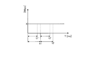
- FIG. 2 is a diagram illustrating an example of a system rate at each time and a time when normal encoding processing is started.
- FIG. 3 is a diagram showing an example of the system rate at each time and the timing when the encoding process of this embodiment is started.
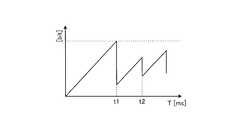
- FIG. 4 is a diagram illustrating an example of a transition of a normal decoder accumulated data amount in the receiving terminal.
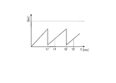
- FIG. 5 is a diagram showing an example of the transition of the decoder accumulated data amount of the present embodiment in the receiving terminal.
- FIG. 6 is a flowchart for explaining the flow of processing of the encoding apparatus.
- FIG. 7 is a diagram illustrating an example of a hardware configuration of a computer according to the encoding device.
- FIG. 1 is a functional block diagram illustrating the configuration of the encoding device according to the first embodiment.
- the encoding device 100 includes a communication I / F 110, a control unit 120, and a storage unit 130.
- the storage unit 130 stores each parameter set in the encoding device 100.
- the storage unit 130 stores a preset first system rate, video rate, audio rate, and decoder accumulation time.
- the storage unit 130 corresponds to, for example, a semiconductor memory device such as a random access memory (RAM), a read only memory (ROM), and a flash memory, and a storage device such as a hard disk or an optical disk.
- the control unit 120 includes an acquisition unit 121, a first calculation unit 122, a second calculation unit 123, a first encoding unit 124, a second encoding unit 125, and a transmission unit 126.
- the function of the control unit 120 can be realized by an integrated circuit such as ASIC (Application Specific Integrated Circuit) or FPGA (Field Programmable Gate Array). Further, the function of the control unit 120 can be realized by, for example, a CPU (Central Processing Unit) executing a predetermined program.
- ASIC Application Specific Integrated Circuit
- FPGA Field Programmable Gate Array
- the acquisition unit 121 acquires each operation parameter in the encoding device from the storage unit 130. For example, the acquiring unit 121 acquires a preset first system rate, video rate, audio rate, and first decoder accumulation time.
- the first system rate is a transmission rate (bps) per second for multiplexing and transmitting video data, audio data, and synchronization data of video data and audio data, and is set in advance from the outside. ing.
- the first system rate may be set based on the encoding time of the encoding device.
- the video rate corresponds to the transmission speed (bps) per second for delivering video to the terminal, and varies depending on the quality of the delivered video.
- the audio rate corresponds to a transmission speed (bps) per second for delivering sound to the terminal, and increases or decreases depending on the sound quality of the delivered sound.
- the first decoder accumulation time is an initial setting value of the time for accumulating encoded data in the buffer of the receiving terminal, and is preset by the outside.
- the first calculation unit 122 calculates the second decoder accumulation time based on the ratio between the first system rate and the second system rate indicating the rate for reproducing video and audio in the terminal.
- the second decoder accumulation time is a decoder accumulation time newly set by the encoding apparatus 100 according to this embodiment. Specifically, the first calculation unit 122 calculates the second decoder accumulation time by the following equation (2).
- the second system rate may be calculated by the second calculation unit 123 described later.
- Second decoder accumulation time first decoder accumulation time / (first system rate / second system rate) (2)
- the second calculation unit 123 calculates the second system rate based on the video rate, the audio rate, and the rate relating to the AV synchronization data for multiplexing and synchronization of the video data and the audio data.
- the second calculation unit 123 may periodically calculate the second system rate and store it in the storage unit 130. Specifically, the second calculator 123 calculates the second system rate using the following equation (3).
- 1st encoding part 124 encodes video data among the data delivered to a terminal.
- the first encoding unit 124 temporarily ends the processing when the amount of data stored in the buffer in the receiving terminal is completed, and stops the encoding until the next data to be encoded is obtained. Also good. Then, the first encoding unit 124 passes the encoded data to the transmission unit 126 when the data encoding is completed.
- the second encoding unit 125 may be similarly encoded for the amount of data stored in the buffer, and the encoded data may be passed to the transmission unit 126 every time encoding is completed.
- the first encoding unit 124 spatially compresses each frame of image data used for video data using a codec for compressing video data. Furthermore, the first encoding unit 124 may perform time compression for acquiring a difference value between frames of image data in parallel with spatial compression. For example, the first encoding unit 124 converts the video data into MPEG-2 Video or H.264. Coding is performed according to a standard such as H.264 / MPEG4AVC.
- 2nd encoding part 125 encodes audio
- the second encoding unit 125 encodes the audio data by compressing it using a codec for compressing the audio data to be distributed.
- the second encoding unit 125 encodes audio data according to standards such as MPEG-1Audio, MPEG2 / 4AAC, and MPEG4HE-AAC.
- the transmission unit 126 generates AV synchronization data for synchronizing video data and audio data. For example, the transmission unit 126 sets a PCR that serves as a reference clock in the MPEG2 TS stream in order to achieve synchronization. Further, the transmission unit 126 may transmit TS packets such as PAT and PMT in an MPEG2 TS stream, for example. Further, the transmission unit 126 adds information related to the second decoder accumulation time to the encoded data.
- the transmission unit 126 multiplexes and transmits the encoded video data and audio data and AV synchronization data for transmission to the terminal. For example, the transmission unit 126 divides the encoded video data, the encoded audio data, and the AV synchronization data into each channel, divides the data into 8 bits, and assigns time to each channel by shifting the time, thereby performing time division multiplexing. May be transmitted.
- the communication I / F 110 is a communication interface for distributing encoded video data, encoded audio data, and AV synchronization data to a terminal via the Internet.
- FIG. 2 is a diagram illustrating an example of a system rate at each time and a time when a normal decoding process is started.
- the horizontal axis represents time T [ms]
- the vertical axis represents system rate [Mbps].
- the system rate continuously changes at a constant X [bps] at each time.
- the terminal performs a decoding process at time t1 and time t2.
- FIG. 3 is a diagram showing an example of the system rate at each time and the timing for starting the encoding process of this embodiment.
- the horizontal axis represents time T [ms]
- the vertical axis represents the system rate [Mbps].
- the system rate continuously changes at a constant X [bps] at each time as in FIG.
- the terminal performs a decoding process at time t1 'earlier than time t1 and at time t2' earlier than time t2.
- the terminal starts the decoding process at t1 'earlier than t1, which is the time to start normal decoding. Thereby, the delay time can be shortened.
- FIG. 4 is a diagram illustrating an example of a transition of a normal decoder accumulated data amount in the receiving terminal.
- the horizontal axis in FIG. 4 represents time T [ms], and the vertical axis represents the amount of data stored in the buffer [bit].
- t1 indicated on the horizontal axis of FIG. 4 indicates the first decoding start time.
- the first data accumulation time at the terminal is between 0 and t1.
- t2 indicates the second decoding start time.
- the second data accumulation time at the terminal is between t1 and t2.
- the amount of data stored in the buffer increases in proportion to the time until the decoding start time t1.
- the accumulated data amount decreases because decoding is started when the decoding start time t1 is reached. Thereafter, the accumulated data amount increases in proportion to the time until the decoding start time t2.
- the decoder accumulation time which is the time from time 0 to the decoding start time t1, is a waiting time until decoding starts, and is added to the delay time.
- FIG. 5 is a diagram showing an example of the transition of the decoder accumulated data amount of the present embodiment in the receiving terminal.
- the horizontal axis in FIG. 5 represents time T [ms], and the vertical axis represents the amount of data stored in the buffer [bit].
- t1 'described on the horizontal axis of FIG. 5 indicates the first decoding start time in the present embodiment.
- the first decoder accumulation time for the first time at the terminal is between 0 and t1 '.
- t2 ' indicates the second decoding start time in the present embodiment.
- the second decoder accumulation time for the second time at the terminal is between t1 and t2 '. Note that t1 in FIG. 4 corresponds to t1 in FIG. 5, and t2 in FIG. 4 corresponds to t2 in FIG.
- the amount of data stored in the buffer increases in proportion to the time until the decoding start time t1 ′.
- the terminal starts decoding.
- Decryption start time t1 ′ is earlier than time t1.
- the amount of accumulated data increases in proportion to time until time t1 'earlier than time t1, and the terminal starts decoding when time t1' is reached. At this time, the amount of accumulated data decreases.
- the amount of stored data increases in proportion to the time until time t2 'that is earlier than time t2, and the terminal starts decoding when time t2' is reached. At this time, the amount of accumulated data decreases.
- the terminal starts decoding the decoded data when the second decoder storage time shorter than the first decoder storage time has elapsed.
- the decoder accumulation time can be shortened and the delay time can be shortened.
- FIG. 6 is a flowchart for explaining the process flow of the encoding apparatus 100.
- the acquiring unit 121 first acquires operating parameters including the first system rate, the video rate, the audio rate, and the first decoder accumulation time from the storage unit 130 (step S10).
- the second calculation unit 123 calculates a second system rate based on the video rate, the audio rate, and the rate related to multiplexing and AV synchronization data (step S11).
- the first calculation unit 122 calculates a second decoder accumulation time based on the obtained first decoder accumulation time, the obtained first system rate, and the second system rate (step S12).
- the first encoding unit 124 encodes video data
- the second encoding unit 125 encodes audio data
- the transmission unit 126 generates AV synchronization data for synchronizing video data and audio data (step S14).
- the transmission unit 126 multiplexes the encoded video data, the encoded audio data, and the AV synchronization data for transmission to the terminal (step S15).
- the transmission unit 126 determines whether to stop the encoding in the first encoding unit 124 and the second encoding unit 125 (step S16). If the second decoding accumulation time has not elapsed since the start of encoding (step S16 No), the transmission unit 126 continues the encoding and repeats the processing from step S13 to step S15. On the other hand, when the second decoding accumulation time has elapsed (Yes in step S16), the transmission unit 126 stops encoding and transmits the multiplexed data to the terminal (step S17).
- the encoding apparatus 100 encodes data received by the terminal based on a first system rate when the data is encoded and transmitted to the terminal and a second system rate indicating a rate at which the data is reproduced by the terminal. Is provided with a first calculation unit 122 for calculating a decoder accumulation time.
- the encoding apparatus 100 further includes a transmission unit 126 that adds information on the decoder accumulation time to the encoded data and transmits the encoded data to the terminal.
- the encoding apparatus 100 further includes a second calculation unit 123 that calculates a second system rate based on the data and data used to multiplex and synchronize the data. As a result, the second system rate reflecting the actual video rate and audio rate is calculated, and the decoder accumulation time can be obtained accurately using this.
- MPEG-2 is used as the codec, but video data and the like may be compressed by other codecs such as MPEG-1 and MPEG-4.
- FIG. 7 is a diagram illustrating an example of a hardware configuration of the computer 200 according to the encoding device 100.
- the computer 200 includes a CPU 201 that executes various arithmetic processes, an input device 202 that receives data input, and a display device 203 that displays information on a monitor or the like when receiving data input.
- the computer 200 also includes a medium reading device 204 that reads a program and the like from a storage medium, and an interface device 205 for connecting to other devices.
- the computer 200 also includes a RAM 206 that temporarily stores various information and a hard disk device 207. Each device 201 to 207 is connected to a bus 208.
- the hard disk device 207 includes an acquisition unit 121, a first calculation unit 122, a second calculation unit 123, a first encoding unit 124, a second encoding unit 125, and a transmission unit 126 of the control unit 120 illustrated in FIG. A program having the same function is stored.
- the hard disk device 207 corresponds to the storage unit 130 and stores operation parameters such as a system rate, a video rate, an audio rate, and a decoder accumulation time.
- the input device 202 accepts input of various operation parameters.
- the CPU 201 reads out each program stored in the hard disk device 207, develops it in the RAM 206, and executes it to perform various processes.
- these programs serve as the acquisition unit 121, the first calculation unit 122, the second calculation unit 123, the first encoding unit 124, the second encoding unit 125, and the transmission unit 126 illustrated in FIG. Can function.
- the computer 200 may read and execute a program stored in a storage medium readable by the computer 200.
- the storage medium readable by the computer 200 corresponds to, for example, a portable recording medium such as a CD-ROM, a DVD disk, a USB (Universal Serial Bus) memory, a semiconductor memory such as a flash memory, and a hard disk drive.
- the program may be stored in a device connected to a public line, the Internet, a LAN (Local Area Network), etc., and the computer 200 may read and execute the program therefrom.
- Encoder 110 Communication I / F 120 control unit 121 acquisition unit 122 first calculation unit 123 second calculation unit 124 first encoding unit 125 second encoding unit 126 transmission unit 130 storage unit
Landscapes
- Engineering & Computer Science (AREA)
- Multimedia (AREA)
- Signal Processing (AREA)
- Compression Or Coding Systems Of Tv Signals (AREA)
Abstract
取得部(121)は符号化装置における各動作パラメータを取得する。第1計算部(122)は、第2のシステムレートと、第1のシステムレートとの比に基づき、第2のデコーダ蓄積時間を算出する。第2計算部(123)は、第2のシステムレートを算出する。第1符号化部(124)は、端末に配信するデータのうち、映像データを符号化する。第2符号化部(125)は、音声データを符号化する。送信部(126)は、符号化された映像データおよび音声データと、AV同期データとを多重化して端末へ送信する。
Description
本発明は、符号化装置、符号化方法、および符号化プログラムに関する。
実況中継による映像を配信する動画配信サイトや、駅構内における乗客を監視する監視システム等においては、端末へ映像がリアルタイムに配信される。ここ最近では、映像配信サービスを受けるユーザの要求により、配信映像の高画質化が進んできており、高画質化を実現するため、配信する映像データのデータ量が増加している。
映像を配信するサーバは、配信する映像データおよび音声データを符号化して、多重化と音声データおよび映像データの同期とに使用するデータを、端末へ送信する。この際、受信端末ではバッファに送信された符号化データを一時的に蓄積し、デコーダ蓄積時間が経過したときに符号化データを復号する。
ところが、配信映像の高画質化に伴い、端末でのデコーダ蓄積時間が増えており、遅延時間が増加する原因となっている。デコーダ蓄積時間が増加すると、端末が配信された符号化データを復号するまでの待ち時間が増加することになる。このため、端末側で配信した映像が実際に撮影された映像よりも遅延して表示されることになり、中継映像との同時進行性が損なわれる。
こうした遅延時間の増加は、ユーザの要求に応えられないだけでなく、システムによっては問題となる場合がある。例えば、駅構内における乗客の監視システムにおいて、端末での映像の変化が実際の撮影映像より遅延することによりホームから転落した乗客の発見が遅れる場合がある。このように、リアルタイム映像配信システムにおいては、配信映像の高画質化だけでなく、遅延時間の短縮も求められている。遅延時間は以下の式(1)で計算できる。
遅延時間 = エンコード時間+ネットワークジッタ吸収時間+デコーダ蓄積時間+デコード時間 ・・・(1)
式(1)において、エンコード時間は、配信サーバにおいて配信データを符号化するための時間である。ネットワークジッタ吸収時間は、配信サーバにおいて配信するパケットにデータを格納するための時間である。デコーダ蓄積時間は、受信データをバッファに蓄積してからデコードを開始するまでの時間である。そして、デコード時間は、符号化データを復号するための時間である。遅延時間うち、デコーダ蓄積時間が占める割合が大きく、デコーダ蓄積時間を短くすることが配信映像の低遅延化に寄与する。
しかしながら、リアルタイムで配信される映像データをエンコードするためのデコーダ蓄積時間を端末側で把握できないという問題がある。
配信映像に変化が少ない場合、配信サーバは端末に差分データを送信すればよいため、配信するデータ量が少なくて済み、デコーダ蓄積時間を短縮しても配信映像の品質に影響は少ない。ところが、映像が急に変化した場合、映像の変化にエンコードが追従できない場合がある。このとき、デコーダ蓄積時間が小さいと、端末側で映像を再生するためのデータが不足し、配信映像の品質が劣化することがある。特に最近では配信映像の高画質化が進んでいるため、端末側で映像を再生するための映像データのデータ量がより大きくなる傾向がある。
すなわち、配信される映像データに基づいて動画を再生するためのデコーダ蓄積時間に関する情報を、端末が取得できない。このため、端末側で設定されたデコーダ蓄積時間が小さすぎる場合、配信映像の品質が劣化する。一方、デコーダ蓄積時間が大きすぎる場合、配信映像の遅延時間が大きくなる。よって、1つの側面では、本発明は、配信映像の品質の向上および遅延時間の短縮を加味したデコード蓄積時間を、端末側が取得可能とする符号化装置、符号化方法、および符号化プログラムを提供することを目的とする。
1つの態様では、符号化装置は、データを符号化して端末へ送信するときの第1のシステムレートと、端末でデータを再生するレートを示す第2のシステムレートとに基づき、端末が受信した符号化データを蓄積するデコーダ蓄積時間を算出する第1計算部を備える。さらに、符号化装置は、符号化データに、デコーダ蓄積時間の情報を付加して端末へ送信する送信部を備える。
一つの側面として、リアルタイムで配信される映像データに基づいて高品質で遅延なく動画を再生するためのデコーダ蓄積時間を端末側で把握できるという効果を奏する。
以下に、本願の開示する符号化装置、符号化方法、および符号化プログラムの実施例を図面に基づいて詳細に説明する。なお、この実施例によりこの発明が限定されるものではない。各実施例は、処理内容を矛盾させない範囲で適宜組み合わせることが可能である。
[符号化装置の機能構成]
実施例1に係る符号化装置の機能構成の一例について説明する。図1は、実施例1に係る符号化装置の構成を示す機能ブロック図である。図1に示すように、この符号化装置100は、通信I/F110と、制御部120、記憶部130とを有する。
実施例1に係る符号化装置の機能構成の一例について説明する。図1は、実施例1に係る符号化装置の構成を示す機能ブロック図である。図1に示すように、この符号化装置100は、通信I/F110と、制御部120、記憶部130とを有する。
記憶部130は、符号化装置100に設定された各パラメータを記憶する。例えば、記憶部130は、予め設定されている第1のシステムレート、ビデオレート、オーディオレート、およびデコーダ蓄積時間を記憶する。記憶部130は、例えば、RAM(Random access Memory)、ROM(Read Only Memory)、フラッシュメモリ(Flash Memory)などの半導体メモリ素子、ハードディスクや光ディスクなどの記憶装置に対応する。
制御部120は、取得部121と、第1計算部122と、第2計算部123と、第1符号化部124と、第2符号化部125と、送信部126とを有する。制御部120の機能は、例えば、ASIC(Application Specific Integrated Circuit)やFPGA(Field Programmable Gate Array)などの集積回路により実現することができる。また、制御部120の機能は、例えば、CPU(Central Processing Unit)が所定のプログラムを実行することで実現することができる。
取得部121は、記憶部130から符号化装置における各動作パラメータを取得する。例えば、取得部121は、予め設定されている第1のシステムレート、ビデオレート、オーディオレート、および第1のデコーダ蓄積時間を取得する。第1のシステムレートとは、映像データ、音声データ、および、映像データと音声データの同期データ等を多重化して送信するための1秒あたりの送信速度(bps)であり、外部より予め設定されている。また、当該第1のシステムレートは符号化装置のエンコード時間に基づいて設定してもよい。ビデオレートは、端末へ映像配信するための1秒あたりの送信速度(bps)に相当し、配信映像の画質により増減する。オーディオレートは、端末へ音声配信するための1秒あたりの送信速度(bps)に相当し、配信音声の音質により増減する。そして、第1のデコーダ蓄積時間は、受信端末のバッファに符号化データを蓄積する時間の初期設定値であり、外部により予め設定されている。
第1計算部122は、端末において映像音声を再生するためのレートを示す第2のシステムレートと、第1のシステムレートとの比に基づき、第2のデコーダ蓄積時間を算出する。第2のデコーダ蓄積時間は、本実施態様に係る符号化装置100より新たに設定されるデコーダ蓄積時間である。具体的には、第1計算部122は、第2のデコーダ蓄積時間を以下の式(2)で計算する。なお、第2のシステムレートは後述する第2計算部123が計算してもよい。
第2のデコーダ蓄積時間 = 第1のデコーダ蓄積時間/(第1のシステムレート/第2のシステムレート) ・・・(2)
例えば、第1計算部122は、第1のデコーダ蓄積時間が500ms、第1のシステムレートが20Mbps、第2のシステムレートが10Mbpsであるとき、これらを式(2)に代入する。そして、第1計算部122は、第2のデコーダ蓄積時間、500ms/(20Mbps/10Mbps)=250msを算出する。
第2計算部123は、ビデオレート、オーディオレート、および多重化と映像データと音声データの同期のためのAV同期データに係るレートに基づき、第2のシステムレートを算出する。第2計算部123は、定期的に第2のシステムレートを算出し、記憶部130に記憶してもよい。具体的には、第2計算部123は、第2のシステムレートを以下の式(3)で計算する。
第2のシステムレート = ビデオレート+オーディオレート+多重化およびAV同期データに係るレート ・・・(3)
例えば、第2計算部123は、ビデオレートが8Mbps、オーディオレートが384kbps、多重化およびAV同期のデータのレートが1.616Mbpsであるとき、式(3)にそれぞれ代入して第2のシステムレートを計算する。そして、第2計算部123は、第2のシステムレートとして、8Mbps+384kbps+1.616Mbps=10Mbpsを算出する。
第1符号化部124は、端末に配信するデータのうち、映像データを符号化する。第1符号化部124は、受信端末におけるバッファの蓄積データ量分の符号化が終了したときに処理を一旦終了し、次の符号化の対象となるデータが得られるまで符号化を停止してもよい。そして、第1符号化部124は、データの符号化が終了した時点で、符号化データを送信部126に渡す。なお、後述する第2符号化部125についても同様にバッファ蓄積データ量分の符号化をおこない、符号化が終了する度に送信部126に符号化データを渡してもよい。
第1符号化部124は、映像データを圧縮するためのコーデックを用いて、映像データに用いられる画像データの各コマを空間圧縮する。さらに、第1符号化部124は、画像データのコマ間の差分値を取得する時間圧縮を、空間圧縮に並行しておこなってもよい。例えば、第1符号化部124は、映像データをMPEG-2VideoやH.264/MPEG4AVC等の規格により符号化をおこなう。
第2符号化部125は、端末に配信するデータのうち、音声データを符号化する。例えば、第2符号化部125は、配信する音声データを圧縮するためのコーデックを用いて、音声データを圧縮することにより符号化する。例えば、第2符号化部125は、音声データをMPEG-1Audio、MPEG2/4AAC、およびMPEG4HE-AAC等の規格により符号化をおこなう。
送信部126は、映像データと音声データの同期をとるためのAV同期データを生成する。例えば、送信部126は、同期をとるために、MPEG2TSストリームにおいて基準となるクロックとなるPCRを設定する。さらに、送信部126は、例えば、MPEG2TSストリームにおいてPAT、PMT等のTSパケットを送信してもよい。さらに、送信部126は、第2のデコーダ蓄積時間に係る情報を符号化データに付加する。
また、送信部126は、符号化された映像データおよび音声データと、AV同期データとを、端末に送信するために多重化して送信する。例えば、送信部126は、符号化映像データ、符号化音声データ、およびAV同期データを、各チャネルに分け、8ビットずつ区切り、時間をずらして各チャネルに時間を割り当てることにより、時分割多重化して送信してもよい。
通信I/F110は、符号化映像データと、符号化音声データと、AV同期データとを、インターネットを介して端末へ配信するための通信インターフェースである。
[各時間におけるシステムレート]
次に、図2および図3を用いて、各時間におけるシステムレートについて説明する。図2は、各時間におけるシステムレートおよび通常の復号化処理を開始する時期の一例を示す図である。図2の横軸は時間T[ms]であり、縦軸はシステムレート[Mbps]を示す。図2のように、システムレートは各時間において一定のX[bps]で連続的に推移している。一方、端末は、時刻t1および時刻t2において復号化処理をおこなう。
次に、図2および図3を用いて、各時間におけるシステムレートについて説明する。図2は、各時間におけるシステムレートおよび通常の復号化処理を開始する時期の一例を示す図である。図2の横軸は時間T[ms]であり、縦軸はシステムレート[Mbps]を示す。図2のように、システムレートは各時間において一定のX[bps]で連続的に推移している。一方、端末は、時刻t1および時刻t2において復号化処理をおこなう。
一方、図3は、各時間におけるシステムレートおよび本実施態様の符号化処理を開始する時期の一例を示す図である。図3の横軸は時間T[ms]であり、縦軸はシステムレート[Mbps]を示す。図3のように、図2と同様にシステムレートは各時間において一定のX[bps]で連続的に推移している。一方、端末は、時刻t1より早い時刻t1’、および時刻t2より早い時刻t2’において復号化処理をおこなう。
すなわち、本実施態様において端末は、通常のデコードを開始する時刻であるt1よりも早いt1’に復号化処理を開始する。これにより、遅延時間を短縮することができる。
[各時間におけるデコーダ蓄積データ量]
次に、図4および図5を用いて、符号化データを受信した端末における通常のデコーダ蓄積データ量および本実施態様のデコーダ蓄積データ量の推移を比較する。図4は、受信端末における通常のデコーダ蓄積データ量の推移の一例を示す図である。図4の横軸は時間T[ms]であり、縦軸はバッファへの蓄積データ量[bit]を示している。また、図4の横軸に記載されているt1は、1回目の復号化開始時刻を示している。また、端末での1回目のデータ蓄積時間は、0-t1間となる。一方、t2は、2回目の復号化開始時刻を示している。また、端末での2回目のデータ蓄積時間は、t1-t2間である。
次に、図4および図5を用いて、符号化データを受信した端末における通常のデコーダ蓄積データ量および本実施態様のデコーダ蓄積データ量の推移を比較する。図4は、受信端末における通常のデコーダ蓄積データ量の推移の一例を示す図である。図4の横軸は時間T[ms]であり、縦軸はバッファへの蓄積データ量[bit]を示している。また、図4の横軸に記載されているt1は、1回目の復号化開始時刻を示している。また、端末での1回目のデータ蓄積時間は、0-t1間となる。一方、t2は、2回目の復号化開始時刻を示している。また、端末での2回目のデータ蓄積時間は、t1-t2間である。
図4において、バッファへの蓄積データ量は、復号化開始時刻t1に至るまでの時間に比例して増加している。蓄積データ量は、復号化開始時刻t1に至るとデコードが開始されるので減少する。その後、蓄積データ量は、復号化開始時刻t2に至るまで時間に比例して増加する。なお、時刻0から復号化開始時刻t1に至るまでの時間であるデコーダ蓄積時間は、デコードを開始するまでの待ち時間となるため、遅延時間に加算される。
一方、図5は、受信端末における本実施態様のデコーダ蓄積データ量の推移の一例を示す図である。図5の横軸は時間T[ms]であり、縦軸はバッファへの蓄積データ量[bit]を示している。また、図5の横軸に記載されているt1’は、本実施態様における1回目の復号化開始時刻を示している。また、端末での1回目の第2のデコーダ蓄積時間は、0-t1’間である。一方、t2’は、本実施態様における2回目の復号化開始時刻を示している。また、端末での2回目の第2のデコーダ蓄積時間は、t1-t2’間である。なお、図4におけるt1は図5におけるt1に対応しており、図4におけるt2は図5におけるt2に対応している。
本実施態様は通常の実施態様と同様に、バッファへの蓄積データ量が復号化開始時刻t1’に至るまでの時間に比例して増加するが、本実施態様においては端末が復号化を開始する復号化開始時刻t1’が時刻t1よりも早くなる。例えば、本実施態様においては、時刻t1より早い時刻t1’に至るまで蓄積データ量が時間に比例して増加し、時刻t1’に至ると端末が復号化を開始する。このとき、蓄積データ量が減少する。次いで、時刻t2よりも早い時刻t2’に至るまで蓄積データ量が時間に比例して増加し、時刻t2’に至ると端末が復号化を開始する。このとき、蓄積データ量が減少する。
すなわち、端末は、第1のデコーダ蓄積時間より短い第2のデコーダ蓄積時間を経過した時に、復号化データの復号を開始する。これにより、デコーダ蓄積時間を短くし、遅延時間を短くできる。
[全体の処理の流れ]
次に、符号化装置100がおこなう全体の処理の流れについて説明する。図6は、符号化装置100の処理の流れを説明するためのフロー図である。図6のように、まず、取得部121は、記憶部130から第1のシステムレート、ビデオレート、オーディオレート、および第1のデコーダ蓄積時間を含む動作パラメータを取得する(ステップS10)。次に、第2計算部123は、ビデオレート、オーディオレート、および多重化とAV同期データに係るレートに基づき、第2のシステムレートを算出する(ステップS11)。次に、第1計算部122は、取得した第1のデコーダ蓄積時間、取得した第1のシステムレート、および第2のシステムレートに基づき第2のデコーダ蓄積時間を計算する(ステップS12)。
次に、符号化装置100がおこなう全体の処理の流れについて説明する。図6は、符号化装置100の処理の流れを説明するためのフロー図である。図6のように、まず、取得部121は、記憶部130から第1のシステムレート、ビデオレート、オーディオレート、および第1のデコーダ蓄積時間を含む動作パラメータを取得する(ステップS10)。次に、第2計算部123は、ビデオレート、オーディオレート、および多重化とAV同期データに係るレートに基づき、第2のシステムレートを算出する(ステップS11)。次に、第1計算部122は、取得した第1のデコーダ蓄積時間、取得した第1のシステムレート、および第2のシステムレートに基づき第2のデコーダ蓄積時間を計算する(ステップS12)。
次に、第1符号化部124は、映像データの符号化をおこない、第2符号化部125は、音声データの符号化をおこなう(ステップS13)。次に、送信部126は、映像データと音声データの同期をとるためのAV同期データを生成する(ステップS14)。次に、送信部126は、符号化映像データと、符号化音声データと、AV同期データとを、端末に送信するために多重化する(ステップS15)。次に、送信部126は、第1符号化部124および第2符号化部125における符号化を停止するかを判定する(ステップS16)。送信部126は、符号化を開始してから第2のデコード蓄積時間を経過していない場合(ステップS16No)は符号化を続行し、ステップS13からステップS15の処理を繰り返す。一方、送信部126は、第2のデコード蓄積時間を経過していた場合(ステップS16Yes)は符号化を停止し、端末へ多重化したデータを送信する(ステップS17)。
[効果]
次に、本実施態様の効果について説明する。符号化装置100は、データを符号化して端末へ送信するときの第1のシステムレートと、端末で前記データを再生するレートを示す第2のシステムレートとに基づき、端末が受信した符号化データを蓄積するデコーダ蓄積時間を算出する第1計算部122を備える。また、符号化装置100は、符号化データに、デコーダ蓄積時間の情報を付加して端末へ送信する送信部126を備える。これにより、デコーダ蓄積時間を短縮しても画質が劣化しないという効果が得られる。
次に、本実施態様の効果について説明する。符号化装置100は、データを符号化して端末へ送信するときの第1のシステムレートと、端末で前記データを再生するレートを示す第2のシステムレートとに基づき、端末が受信した符号化データを蓄積するデコーダ蓄積時間を算出する第1計算部122を備える。また、符号化装置100は、符号化データに、デコーダ蓄積時間の情報を付加して端末へ送信する送信部126を備える。これにより、デコーダ蓄積時間を短縮しても画質が劣化しないという効果が得られる。
また、符号化装置100は、データと、データを多重化および同期するのに用いるデータとに基づき、第2のシステムレートを算出する第2計算部123をさらに備える。これにより、実際のビデオレートおよびオーディオレートを反映した第2のシステムレートを算出し、これを用いてデコーダ蓄積時間を精度よく取得できる。
なお、実施例1においては、コーデックにMPEG-2を使用したが、MPEG-1、MPEG-4等の他のコーデックにより映像データ等の圧縮をおこなってもよい。
図7は、符号化装置100に係るコンピュータ200のハードウェア構成の一例を示す図である。図7が示すように、コンピュータ200は、各種演算処理を実行するCPU201と、データ入力を受け付ける入力装置202と、データ入力を受け付ける際、モニタ等に情報を表示する表示装置203とを有する。また、コンピュータ200は、記憶媒体からプログラム等を読み取る媒体読取装置204と、他の装置と接続するためのインターフェース装置205とを有する。また、コンピュータ200は、各種情報を一時記憶するRAM206と、ハードディスク装置207とを有する。また、各装置201~207は、バス208に接続される。
ハードディスク装置207には、図1に示した制御部120の取得部121、第1計算部122、第2計算部123、第1符号化部124、第2符号化部125、および送信部126と同様の機能を有するプログラムが記憶される。また、ハードディスク装置207は、記憶部130に対応し、システムレート、ビデオレート、オーディオレート、およびデコーダ蓄積時間等の動作パラメータを記憶する。また、入力装置202は、各種動作パラメータの入力を受け付ける。
CPU201は、ハードディスク装置207に記憶された各プログラムを読み出して、RAM206に展開して実行することで、各種の処理を行う。また、これらのプログラムは、コンピュータ200を図1に示した取得部121、第1計算部122、第2計算部123、第1符号化部124、第2符号化部125、および送信部126として機能させることができる。
なお、上記の符号化プログラムは、必ずしもハードディスク装置207に記憶されている必要はない。例えば、コンピュータ200が読み取り可能な記憶媒体に記憶されたプログラムを、コンピュータ200が読み出して実行するようにしてもよい。コンピュータ200が読み取り可能な記憶媒体は、例えば、CD-ROMやDVDディスク、USB(Universal Serial Bus)メモリ等の可搬型記録媒体、フラッシュメモリ等の半導体メモリ、ハードディスクドライブ等が対応する。また、公衆回線、インターネット、LAN(Local Area Network)等に接続された装置にこのプログラムを記憶させておき、コンピュータ200がこれらからプログラムを読み出して実行するようにしてもよい。
100 符号化装置
110 通信I/F
120 制御部
121 取得部
122 第1計算部
123 第2計算部
124 第1符号化部
125 第2符号化部
126 送信部
130 記憶部
110 通信I/F
120 制御部
121 取得部
122 第1計算部
123 第2計算部
124 第1符号化部
125 第2符号化部
126 送信部
130 記憶部
Claims (5)
- データを符号化して端末へ送信するときの第1のシステムレートと、前記端末で前記データを再生するレートを示す第2のシステムレートとに基づき、前記端末が受信した符号化データを蓄積するデコーダ蓄積時間を算出する第1計算部と、
前記符号化データに、前記デコーダ蓄積時間の情報を付加して前記端末へ送信する送信部と
を備えたことを特徴とする符号化装置。 - 前記データと、該データを多重化および同期するのに用いるデータとに基づき、前記第2のシステムレートを算出する第2計算部をさらに備えることを特徴とする請求項1に記載の符号化装置。
- 符号化データを端末へ送信する符号化装置と、受信した前記符号化データを復号する端末とを有するシステムであって、
前記符号化装置は、
データを符号化して端末へ送信するときの第1のシステムレートと、前記端末で前記データを再生するレートを示す第2のシステムレートとに基づき、前記端末が受信した符号化データを蓄積するデコーダ蓄積時間を算出する第1計算部と、
前記符号化データに、前記デコーダ蓄積時間の情報を付加して前記端末へ送信する送信部と、を備え、
前記端末は、受信した前記符号化データを記憶領域に蓄積し、デコーダ蓄積時間経過時に復号することを特徴とするシステム。 - コンピュータが実行する符号化方法であって、
データを符号化して端末へ送信するときの第1のシステムレートと、前記端末で前記データを再生するレートを示す第2のシステムレートとに基づき、前記端末が受信した符号化データを蓄積するデコーダ蓄積時間を算出し、
前記符号化データに、前記デコーダ蓄積時間の情報を付加して前記端末へ送信する
処理を実行することを特徴とする符号化方法。 - コンピュータに、
データを符号化して端末へ送信するときの第1のシステムレートと、前記端末で前記データを再生するレートを示す第2のシステムレートとに基づき、前記端末が受信した符号化データを蓄積するデコーダ蓄積時間を算出し、
前記符号化データに、前記デコーダ蓄積時間の情報を付加して前記端末へ送信する
処理を実行させることを特徴とする符号化プログラム。
Priority Applications (4)
| Application Number | Priority Date | Filing Date | Title |
|---|---|---|---|
| EP13890151.7A EP3026907B1 (en) | 2013-07-26 | 2013-07-26 | Encoding device, encoding method, and encoding program |
| JP2015528092A JP6146471B2 (ja) | 2013-07-26 | 2013-07-26 | 符号化装置、符号化方法、および符号化プログラム |
| PCT/JP2013/070395 WO2015011841A1 (ja) | 2013-07-26 | 2013-07-26 | 符号化装置、符号化方法、および符号化プログラム |
| US15/000,805 US10284865B2 (en) | 2013-07-26 | 2016-01-19 | Encoding device, encoding method, and recording medium |
Applications Claiming Priority (1)
| Application Number | Priority Date | Filing Date | Title |
|---|---|---|---|
| PCT/JP2013/070395 WO2015011841A1 (ja) | 2013-07-26 | 2013-07-26 | 符号化装置、符号化方法、および符号化プログラム |
Related Child Applications (1)
| Application Number | Title | Priority Date | Filing Date |
|---|---|---|---|
| US15/000,805 Continuation US10284865B2 (en) | 2013-07-26 | 2016-01-19 | Encoding device, encoding method, and recording medium |
Publications (1)
| Publication Number | Publication Date |
|---|---|
| WO2015011841A1 true WO2015011841A1 (ja) | 2015-01-29 |
Family
ID=52392917
Family Applications (1)
| Application Number | Title | Priority Date | Filing Date |
|---|---|---|---|
| PCT/JP2013/070395 Ceased WO2015011841A1 (ja) | 2013-07-26 | 2013-07-26 | 符号化装置、符号化方法、および符号化プログラム |
Country Status (4)
| Country | Link |
|---|---|
| US (1) | US10284865B2 (ja) |
| EP (1) | EP3026907B1 (ja) |
| JP (1) | JP6146471B2 (ja) |
| WO (1) | WO2015011841A1 (ja) |
Families Citing this family (1)
| Publication number | Priority date | Publication date | Assignee | Title |
|---|---|---|---|---|
| TWI762908B (zh) * | 2020-04-17 | 2022-05-01 | 新唐科技股份有限公司 | 串接式擴增裝置及包含其之串接式系統 |
Citations (4)
| Publication number | Priority date | Publication date | Assignee | Title |
|---|---|---|---|---|
| JPH09298734A (ja) | 1996-04-30 | 1997-11-18 | Matsushita Electric Ind Co Ltd | ビデオオンデマンドシステム |
| JP2000124958A (ja) * | 1998-10-20 | 2000-04-28 | Mitsubishi Electric Corp | 符号化データ切替装置 |
| JP2002084339A (ja) | 2000-07-06 | 2002-03-22 | Matsushita Electric Ind Co Ltd | ストリーミング方法およびそれを実行するシステム |
| JP2011130065A (ja) * | 2009-12-16 | 2011-06-30 | Sony Corp | 送信装置および方法、並びに、受信装置および方法 |
Family Cites Families (3)
| Publication number | Priority date | Publication date | Assignee | Title |
|---|---|---|---|---|
| EP1182875A3 (en) | 2000-07-06 | 2003-11-26 | Matsushita Electric Industrial Co., Ltd. | Streaming method and corresponding system |
| US7266147B2 (en) * | 2003-03-31 | 2007-09-04 | Sharp Laboratories Of America, Inc. | Hypothetical reference decoder |
| US8218439B2 (en) * | 2004-11-24 | 2012-07-10 | Sharp Laboratories Of America, Inc. | Method and apparatus for adaptive buffering |
-
2013
- 2013-07-26 JP JP2015528092A patent/JP6146471B2/ja not_active Expired - Fee Related
- 2013-07-26 WO PCT/JP2013/070395 patent/WO2015011841A1/ja not_active Ceased
- 2013-07-26 EP EP13890151.7A patent/EP3026907B1/en not_active Not-in-force
-
2016
- 2016-01-19 US US15/000,805 patent/US10284865B2/en active Active
Patent Citations (4)
| Publication number | Priority date | Publication date | Assignee | Title |
|---|---|---|---|---|
| JPH09298734A (ja) | 1996-04-30 | 1997-11-18 | Matsushita Electric Ind Co Ltd | ビデオオンデマンドシステム |
| JP2000124958A (ja) * | 1998-10-20 | 2000-04-28 | Mitsubishi Electric Corp | 符号化データ切替装置 |
| JP2002084339A (ja) | 2000-07-06 | 2002-03-22 | Matsushita Electric Ind Co Ltd | ストリーミング方法およびそれを実行するシステム |
| JP2011130065A (ja) * | 2009-12-16 | 2011-06-30 | Sony Corp | 送信装置および方法、並びに、受信装置および方法 |
Also Published As
| Publication number | Publication date |
|---|---|
| EP3026907A4 (en) | 2016-06-01 |
| US20160150239A1 (en) | 2016-05-26 |
| EP3026907B1 (en) | 2018-04-18 |
| JPWO2015011841A1 (ja) | 2017-03-02 |
| US10284865B2 (en) | 2019-05-07 |
| EP3026907A1 (en) | 2016-06-01 |
| JP6146471B2 (ja) | 2017-06-14 |
Similar Documents
| Publication | Publication Date | Title |
|---|---|---|
| US12361974B2 (en) | Data transmission method, data playback method, data transmission device, and data playback device | |
| JP4837744B2 (ja) | 多重化装置、集積回路、多重化方法、多重化プログラム、多重化プログラムを記録したコンピュータ読み取り可能な記録媒体及び多重化ストリームを記録したコンピュータ読み取り可能な記録媒体 | |
| CN103155580B (zh) | 不同质量级别的自适应视频流 | |
| US10177899B2 (en) | Adapting a jitter buffer | |
| US8996713B2 (en) | Video streaming | |
| TW201301899A (zh) | 減少視訊編碼及解碼中之延遲 | |
| CN104735470A (zh) | 一种流媒体数据传输方法及装置 | |
| WO2016008131A1 (en) | Techniques for separately playing audio and video data in local networks | |
| EP1941661A4 (en) | SYSTEM AND METHOD FOR CONTROLLING THE TRANSMISSION OF MOBILE PHOTOGRAPHY DATA THROUGH A NETWORK | |
| JP2010287973A (ja) | 情報処理装置および方法、並びにプログラム | |
| JP6146471B2 (ja) | 符号化装置、符号化方法、および符号化プログラム | |
| US9467691B2 (en) | Video system for displaying image data, method and computer program | |
| CN103475906B (zh) | 用于多媒体流的测量方法和测量装置 | |
| CN107087210B (zh) | 基于缓存时间判断视频播放状态的方法及终端 | |
| JP2023161219A (ja) | 送信装置、受信装置及びそれらのプログラム | |
| KR20100125692A (ko) | 비대칭 스케일러블 다운로딩 방법 및 시스템 | |
| JPH11313320A (ja) | データ符号化装置および動画像データ符号化方法 |
Legal Events
| Date | Code | Title | Description |
|---|---|---|---|
| 121 | Ep: the epo has been informed by wipo that ep was designated in this application |
Ref document number: 13890151 Country of ref document: EP Kind code of ref document: A1 |
|
| ENP | Entry into the national phase |
Ref document number: 2015528092 Country of ref document: JP Kind code of ref document: A |
|
| WWE | Wipo information: entry into national phase |
Ref document number: 2013890151 Country of ref document: EP |
|
| NENP | Non-entry into the national phase |
Ref country code: DE |