WO2015012293A1 - Module de membrane à fibres creuses de perfusion externe et imprimante à jet d'encre dotée dudit module - Google Patents
Module de membrane à fibres creuses de perfusion externe et imprimante à jet d'encre dotée dudit module Download PDFInfo
- Publication number
- WO2015012293A1 WO2015012293A1 PCT/JP2014/069396 JP2014069396W WO2015012293A1 WO 2015012293 A1 WO2015012293 A1 WO 2015012293A1 JP 2014069396 W JP2014069396 W JP 2014069396W WO 2015012293 A1 WO2015012293 A1 WO 2015012293A1
- Authority
- WO
- WIPO (PCT)
- Prior art keywords
- hollow fiber
- fiber membrane
- case
- liquid
- membrane bundle
- Prior art date
- Legal status (The legal status is an assumption and is not a legal conclusion. Google has not performed a legal analysis and makes no representation as to the accuracy of the status listed.)
- Ceased
Links
Images


Classifications
-
- B—PERFORMING OPERATIONS; TRANSPORTING
- B01—PHYSICAL OR CHEMICAL PROCESSES OR APPARATUS IN GENERAL
- B01D—SEPARATION
- B01D19/00—Degasification of liquids
- B01D19/0031—Degasification of liquids by filtration
-
- B—PERFORMING OPERATIONS; TRANSPORTING
- B01—PHYSICAL OR CHEMICAL PROCESSES OR APPARATUS IN GENERAL
- B01D—SEPARATION
- B01D63/00—Apparatus in general for separation processes using semi-permeable membranes
- B01D63/02—Hollow fibre modules
-
- B—PERFORMING OPERATIONS; TRANSPORTING
- B01—PHYSICAL OR CHEMICAL PROCESSES OR APPARATUS IN GENERAL
- B01D—SEPARATION
- B01D63/00—Apparatus in general for separation processes using semi-permeable membranes
- B01D63/02—Hollow fibre modules
- B01D63/021—Manufacturing thereof
- B01D63/0233—Manufacturing thereof forming the bundle
-
- B—PERFORMING OPERATIONS; TRANSPORTING
- B01—PHYSICAL OR CHEMICAL PROCESSES OR APPARATUS IN GENERAL
- B01D—SEPARATION
- B01D63/00—Apparatus in general for separation processes using semi-permeable membranes
- B01D63/02—Hollow fibre modules
- B01D63/024—Hollow fibre modules with a single potted end
- B01D63/0241—Hollow fibre modules with a single potted end being U-shaped
-
- B—PERFORMING OPERATIONS; TRANSPORTING
- B01—PHYSICAL OR CHEMICAL PROCESSES OR APPARATUS IN GENERAL
- B01D—SEPARATION
- B01D63/00—Apparatus in general for separation processes using semi-permeable membranes
- B01D63/02—Hollow fibre modules
- B01D63/04—Hollow fibre modules comprising multiple hollow fibre assemblies
-
- B—PERFORMING OPERATIONS; TRANSPORTING
- B01—PHYSICAL OR CHEMICAL PROCESSES OR APPARATUS IN GENERAL
- B01D—SEPARATION
- B01D69/00—Semi-permeable membranes for separation processes or apparatus characterised by their form, structure or properties; Manufacturing processes specially adapted therefor
- B01D69/08—Hollow fibre membranes
- B01D69/081—Hollow fibre membranes characterised by the fibre diameter
-
- B—PERFORMING OPERATIONS; TRANSPORTING
- B01—PHYSICAL OR CHEMICAL PROCESSES OR APPARATUS IN GENERAL
- B01D—SEPARATION
- B01D69/00—Semi-permeable membranes for separation processes or apparatus characterised by their form, structure or properties; Manufacturing processes specially adapted therefor
- B01D69/10—Supported membranes; Membrane supports
-
- B—PERFORMING OPERATIONS; TRANSPORTING
- B01—PHYSICAL OR CHEMICAL PROCESSES OR APPARATUS IN GENERAL
- B01D—SEPARATION
- B01D69/00—Semi-permeable membranes for separation processes or apparatus characterised by their form, structure or properties; Manufacturing processes specially adapted therefor
- B01D69/12—Composite membranes; Ultra-thin membranes
- B01D69/1213—Laminated layers
-
- B—PERFORMING OPERATIONS; TRANSPORTING
- B41—PRINTING; LINING MACHINES; TYPEWRITERS; STAMPS
- B41J—TYPEWRITERS; SELECTIVE PRINTING MECHANISMS, i.e. MECHANISMS PRINTING OTHERWISE THAN FROM A FORME; CORRECTION OF TYPOGRAPHICAL ERRORS
- B41J2/00—Typewriters or selective printing mechanisms characterised by the printing or marking process for which they are designed
- B41J2/005—Typewriters or selective printing mechanisms characterised by the printing or marking process for which they are designed characterised by bringing liquid or particles selectively into contact with a printing material
- B41J2/01—Ink jet
- B41J2/17—Ink jet characterised by ink handling
- B41J2/175—Ink supply systems ; Circuit parts therefor
- B41J2/17563—Ink filters
-
- B—PERFORMING OPERATIONS; TRANSPORTING
- B41—PRINTING; LINING MACHINES; TYPEWRITERS; STAMPS
- B41J—TYPEWRITERS; SELECTIVE PRINTING MECHANISMS, i.e. MECHANISMS PRINTING OTHERWISE THAN FROM A FORME; CORRECTION OF TYPOGRAPHICAL ERRORS
- B41J2/00—Typewriters or selective printing mechanisms characterised by the printing or marking process for which they are designed
- B41J2/005—Typewriters or selective printing mechanisms characterised by the printing or marking process for which they are designed characterised by bringing liquid or particles selectively into contact with a printing material
- B41J2/01—Ink jet
- B41J2/17—Ink jet characterised by ink handling
- B41J2/19—Ink jet characterised by ink handling for removing air bubbles
-
- B—PERFORMING OPERATIONS; TRANSPORTING
- B01—PHYSICAL OR CHEMICAL PROCESSES OR APPARATUS IN GENERAL
- B01D—SEPARATION
- B01D2311/00—Details relating to membrane separation process operations and control
- B01D2311/26—Further operations combined with membrane separation processes
- B01D2311/2653—Degassing
- B01D2311/2657—Deaeration
-
- B—PERFORMING OPERATIONS; TRANSPORTING
- B01—PHYSICAL OR CHEMICAL PROCESSES OR APPARATUS IN GENERAL
- B01D—SEPARATION
- B01D2313/00—Details relating to membrane modules or apparatus
- B01D2313/08—Flow guidance means within the module or the apparatus
-
- B—PERFORMING OPERATIONS; TRANSPORTING
- B01—PHYSICAL OR CHEMICAL PROCESSES OR APPARATUS IN GENERAL
- B01D—SEPARATION
- B01D2313/00—Details relating to membrane modules or apparatus
- B01D2313/10—Specific supply elements
-
- B—PERFORMING OPERATIONS; TRANSPORTING
- B01—PHYSICAL OR CHEMICAL PROCESSES OR APPARATUS IN GENERAL
- B01D—SEPARATION
- B01D2313/00—Details relating to membrane modules or apparatus
- B01D2313/20—Specific housing
- B01D2313/205—Specific housing characterised by the shape
-
- B—PERFORMING OPERATIONS; TRANSPORTING
- B01—PHYSICAL OR CHEMICAL PROCESSES OR APPARATUS IN GENERAL
- B01D—SEPARATION
- B01D2325/00—Details relating to properties of membranes
- B01D2325/24—Mechanical properties, e.g. strength
Definitions
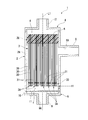
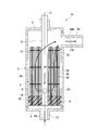
- FIG. 1 shows an external perfusion type deaeration module 1 according to a first embodiment of the present invention.
- the deaeration module 1 includes a case 2 and a hollow fiber membrane bundle 3 housed in the case 2.
- the case 2 includes a cylindrical case body 2A, a first lid member 4 that covers one end opening of the case body 2A, and a second lid member 5 that covers the other end opening of the case body 2A.
- the case 2 forms a substantially cylindrical appearance by combining the case main body 2A, the first lid member 4, and the second lid member 5.
- the deaeration module 1 is used in an inkjet discharge apparatus such as an inkjet printer or a color filter manufacturing apparatus, but its application is not particularly limited.
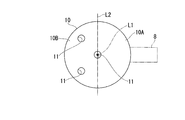
- reference numeral L1 denotes a central axis of the case 2 (hereinafter, simply referred to as “axial”) extending in the axial direction of the case 2 through the center of the cross section of the case 2 along the direction orthogonal to the axial direction of the case 2 (case body 2A). Sometimes called the center).
- the center of the cross section of the case 2 means the center of gravity in a cross section perpendicular to the direction in which the hollow fiber membrane 30 extends (longitudinal direction of the case 2).
- the first lid member 4 is disposed on the upper side
- the second lid member 5 is disposed on the lower side.
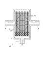
- FIG. 4 shows a liquid flow in the deaeration module 1 according to the present embodiment.
- the liquid flows into the case 2 through the inlet 9 ⁇ / b> A of the second port 9 as indicated by the arrow ⁇ .
- the liquid flowing into the case 2 flows from the opening 11 of the dispersion plate 10 to the upper chamber of the dispersion plate 10 in the liquid chamber f, and is directed to the first port 8 as indicated by the arrow ⁇ . Flowing diagonally. A large amount of liquid flowing from the opening 11 flows from the side opposite to the side where the first port 8 side is formed.
- the hollow fiber membrane 30 has gas permeability that allows gas to pass between the hollow portion and the outside of the hollow fiber membrane 30.
- the outer diameter of the hollow fiber membrane 30 is preferably 280 ⁇ m or less, and more preferably 250 ⁇ m or less. More specifically, the thickness is preferably 250 to 150 ⁇ m, and more preferably 220 to 180 ⁇ m. When the outer diameter of the hollow fiber membrane 30 is within the above numerical range, an efficient channel can be formed between the hollow fiber membranes in the case.
- the inner diameter of the hollow fiber membrane 30 is preferably 100 ⁇ m or more, and more preferably 120 ⁇ m or more.
- the inner diameter of the hollow fiber membrane 30 is preferably 200 ⁇ m or less.
- the inner diameter and outer diameter of the hollow fiber membrane are measured as follows. First, several hollow fiber membranes are bundled and the entire outside thereof is covered with polyurethane resin and cured. Next, the cured bundle is sliced along the radial direction of the hollow fiber membrane so that the length in the longitudinal direction is several mm, thereby obtaining a flaky sample having a thickness of several mm. Next, an optical image of the cross section of the sample is projected onto a screen at a magnification of, for example, 100 using a projector. In the projected image, the outer diameter and inner diameter of each hollow fiber membrane are measured. The operation of cutting out and measuring the sample in this manner is repeated five times or more, and the average value of all the numerical values is taken as the outer diameter and inner diameter of the hollow fiber membrane
- the material for the porous support layer examples include silicon rubber-based resins such as polydimethylsiloxane, a copolymer of silicon and polycarbonate; polyolefins such as poly-4-methylpentene-1, poly-3-methylbutene-1, low-density polyethylene, and polypropylene Fluorine-containing resins such as polyvinylidene fluoride and polytetrafluoroethylene; Cellulose resins such as ethyl cellulose; Polyphenylene oxide; Poly-4-vinylpyridine; Urethane resins; Polystyrene; Polyetheretherketone; Polyetherketone . These resins may be used alone or in a blend of two or more. Also, copolymers of these resins can be used.
- silicon rubber-based resins such as polydimethylsiloxane, a copolymer of silicon and polycarbonate
- polyolefins such as poly-4-methylpentene-1, poly-3-methylbutene-1
- the thicknesses of the homogeneous layer and the porous support layer are preferably determined so that the film thickness falls within the above range, and within that range, the thickness of the homogeneous layer is preferably 0.3 to 2 ⁇ m.
- the thickness of the porous support layer is preferably 20 to 70 ⁇ m, more preferably 25 to 55 ⁇ m.
- the thickness of the porous support layer refers to the case where the porous support layer is composed of a plurality of layers (for example, a total of two porous support layers, one on each of the inner side and the outer side of the homogeneous layer). In other cases, the total thickness of the plurality of layers.
- ⁇ a indicates the flow of liquid in the case 2. Also in the configuration of the present embodiment, as referred to by the arrow ⁇ a, the liquid goes to the first port 8 while contacting the wide range of the extending direction of the hollow fiber membrane bundle 3. Also in this embodiment, the same effect as the first embodiment can be obtained.
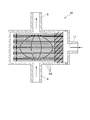
- the deaeration module 1a ′′ according to the fifth embodiment includes the first port 8 on one end side and the second port on the other end side in the deaeration module 1a according to the fourth embodiment. It is installed.
- the deaeration module 1 a ′′ is configured to allow liquid to flow from the second port 9 toward the first port 8.
- the second port 9 is an inflow port and the first port 8 is an outflow port.
- the first port 8 may be an inflow port and the second port 9 may be an outflow port. Good.
- the first port 8 and the second port 9 are separated from each other in the horizontal direction.
- the positions of the first port 8 and the second port 9 are particularly limited. Is not to be done.
- the first port 8 may be installed on one end side as in the fifth embodiment, or the second port 9 may be installed on the other end side.
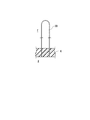
- each small bundle 3A the hollow fiber membrane 30 is folded in a U shape, and both end portions thereof are embedded in the potting portion 6, and both end portions thereof are opened to the air chamber g. ing.
- the inside of each hollow fiber membrane 30 is in a state communicating with the air chamber g. That is, in the present embodiment, both end portions of the hollow fiber membrane 30 form a lower end portion (one end portion) and are fixed in the case 2 by the potting portion 6 in an open state.
- the outer surface of the portion of each hollow fiber membrane 30 that extends upward from the potting portion 6 is exposed to the liquid chamber f, and its U-shaped bottom portion points upward. It is in a state. Therefore, the upper end portion of each hollow fiber membrane 30 (that is, the hollow fiber membrane bundle 3) is a free end. That is, in this embodiment, the U-shaped bottom portion of the hollow fiber membrane 30 forms the upper end portion (the other end portion).
- the liquid flowing into and out of the case 2 is pumped by a pump (not shown) and introduced into the case 2.
- the pump may be arranged on the downstream side of the outflow port 9b to draw in the liquid, or may be arranged on the upstream side of the pipe member 15 to push out the liquid.
- the material of the homogeneous layer is preferably a polyolefin resin, and more preferably a polyolefin resin having a density of 0.850 to 0.910 g / cm 3 .
- a homogeneous layer formed of a polyolefin resin having a density within the above range has excellent degassing performance and a practically suitable melting point or softening point even when a liquid to be treated is passed at a high flow rate.
- the unstretched hollow fiber is stretched to make the inner layer and the outer layer porous (stretched porous process).
- a hollow fiber membrane having a three-layer structure including a homogeneous layer and a porous support layer that is located inside and outside the homogeneous layer and supports the homogeneous layer is obtained.
- the hollow fiber membrane bundle 3 is fixed in the case 2 by the potting portion 6 only at its upper end 3U, and extends downward along the central axis L1 from the potting portion 6.
- the hollow fiber membrane bundle 3 has a plurality of small bundles 3A as in the first embodiment, and each small bundle 3A has a warp 31 extending in a direction orthogonal to the central axis L1 only at a lower portion thereof.
- One is provided, and a plurality of hollow fiber membranes 30 are bundled by warps 31.
- the warp 31 may connect a plurality of small bundles 3A, or a plurality of warps 31 may be provided at appropriate positions of the small bundles 3A.
- the pipe member 15 has an upper end portion embedded in the potting portion 6, extends downward along the central axis L ⁇ b> 1, and a lower end portion disposed in the liquid chamber f in the case 2.
- the lower end portion of the pipe member 15 is opened, and the upper end portion is liquid-tight and air-tightly sealed by the plug body 15A.
- the tube member 15 is formed with a plurality of inlets 16 through which liquid flows into the case 2. Thereby, the pipe member 15 communicates with the inside of the case 2 via the inflow port 16.
Landscapes
- Chemical & Material Sciences (AREA)
- Chemical Kinetics & Catalysis (AREA)
- Engineering & Computer Science (AREA)
- Manufacturing & Machinery (AREA)
- Separation Using Semi-Permeable Membranes (AREA)
- Degasification And Air Bubble Elimination (AREA)
- Ink Jet (AREA)
Abstract
Priority Applications (8)
| Application Number | Priority Date | Filing Date | Title |
|---|---|---|---|
| KR1020167001924A KR102015263B1 (ko) | 2013-07-24 | 2014-07-23 | 외부 관류형 중공사막 모듈 및 상기 모듈을 갖는 잉크젯 프린터 |
| CA2918931A CA2918931C (fr) | 2013-07-24 | 2014-07-23 | Module de membrane a fibres creuses de perfusion externe et imprimante a jet d'encre dotee dudit module |
| US14/906,726 US9821251B2 (en) | 2013-07-24 | 2014-07-23 | External-perfusion hollow-fiber membrade module and inkjet printer having said module |
| EP14829502.5A EP3025775A4 (fr) | 2013-07-24 | 2014-07-23 | Module de membrane à fibres creuses de perfusion externe et imprimante à jet d'encre dotée dudit module |
| CN201480046511.5A CN105517693B (zh) | 2013-07-24 | 2014-07-23 | 外部灌注型中空纤维膜组件及具有所述组件的喷墨打印机 |
| KR1020187015744A KR20180064570A (ko) | 2013-07-24 | 2014-07-23 | 외부 관류형 중공사막 모듈 및 상기 모듈을 갖는 잉크젯 프린터 |
| JP2014538011A JP6618067B2 (ja) | 2013-07-24 | 2014-07-23 | 外部灌流型の中空糸膜モジュール及び前記モジュールを有するインクジェットプリンタ |
| IL243716A IL243716B (en) | 2013-07-24 | 2016-01-21 | A module with a hollow fiber membrane for external infusion and an ink-jet printer containing it |
Applications Claiming Priority (4)
| Application Number | Priority Date | Filing Date | Title |
|---|---|---|---|
| JP2013153866 | 2013-07-24 | ||
| JP2013-153866 | 2013-07-24 | ||
| JP2013153865 | 2013-07-24 | ||
| JP2013-153865 | 2013-07-24 |
Publications (1)
| Publication Number | Publication Date |
|---|---|
| WO2015012293A1 true WO2015012293A1 (fr) | 2015-01-29 |
Family
ID=52393326
Family Applications (1)
| Application Number | Title | Priority Date | Filing Date |
|---|---|---|---|
| PCT/JP2014/069396 Ceased WO2015012293A1 (fr) | 2013-07-24 | 2014-07-23 | Module de membrane à fibres creuses de perfusion externe et imprimante à jet d'encre dotée dudit module |
Country Status (9)
| Country | Link |
|---|---|
| US (1) | US9821251B2 (fr) |
| EP (1) | EP3025775A4 (fr) |
| JP (2) | JP6618067B2 (fr) |
| KR (2) | KR20180064570A (fr) |
| CN (1) | CN105517693B (fr) |
| CA (1) | CA2918931C (fr) |
| IL (1) | IL243716B (fr) |
| TW (1) | TWI648172B (fr) |
| WO (1) | WO2015012293A1 (fr) |
Cited By (9)
| Publication number | Priority date | Publication date | Assignee | Title |
|---|---|---|---|---|
| CN106334456A (zh) * | 2016-10-21 | 2017-01-18 | 中国科学院大连化学物理研究所 | 一种中空纤维分离膜组件 |
| WO2017195818A1 (fr) * | 2016-05-11 | 2017-11-16 | 三菱ケミカル・クリンスイ株式会社 | Module de membranes à fibres creuses |
| WO2018230631A1 (fr) | 2017-06-14 | 2018-12-20 | 三菱ケミカル・クリンスイ株式会社 | Module à membranes à fibres creuses du type à circulation externe |
| JP2020018979A (ja) * | 2018-08-02 | 2020-02-06 | 株式会社クラレ | 中空糸膜モジュール |
| WO2020067512A1 (fr) * | 2018-09-27 | 2020-04-02 | Dic株式会社 | Système de dégazéification, procédé de dégazéification de liquide, module de dégazéification, procédé de fabrication de système de dégazéification et procédé de production de ressources naturelles |
| DE102018129165A1 (de) * | 2018-11-20 | 2020-05-20 | UMS Gmbh & Co KG | Gasdruckmessvorrichtung mit Hohlfasermembranbündel |
| DE102018131355A1 (de) * | 2018-12-07 | 2020-06-10 | UMS Gmbh & Co KG | Gesamtgas-Messvorrichtung mit Formkörper |
| WO2020138096A1 (fr) * | 2018-12-28 | 2020-07-02 | Dic株式会社 | Système de dégazage, procédé de dégazage de liquides, unité de dégazage, module de dégazage, et procédé de fabrication de système de dégazage et procédé de production à partir de ressources naturelles |
| CN113316476A (zh) * | 2019-01-22 | 2021-08-27 | 日东电工株式会社 | 分离膜组件和使用该分离膜组件的液体处理系统 |
Families Citing this family (15)
| Publication number | Priority date | Publication date | Assignee | Title |
|---|---|---|---|---|
| US20160310903A1 (en) * | 2015-04-22 | 2016-10-27 | Mann+Hummel Gmbh | Hollow Fiber Module, Fluid Treatment Device, and Method of Forming a Hollow Fiber Module |
| HUE071601T2 (hu) * | 2016-05-31 | 2025-09-28 | Toray Industries | Membrán modul üreges szálakkal |
| EP3501628A4 (fr) * | 2016-08-17 | 2020-01-08 | Mitsubishi Chemical Cleansui Corporation | Module de membrane à fibres creuses, dispositif de dégazage et d'alimentation en gaz, imprimante à jet d'encre et dispositif de fabrication de ressort carboné |
| US11273282B2 (en) * | 2016-10-20 | 2022-03-15 | Vapotherm, Inc. | Vapor transfer cartridge |
| USD833004S1 (en) | 2016-10-20 | 2018-11-06 | Vapotherm, Inc. | Vapor transfer cartridge for use in a respiratory therapy system |
| DE102016012730A1 (de) * | 2016-10-24 | 2018-04-26 | Fresenius Medical Care Deutschland Gmbh | Verfahren zur Bestimmung einer Permeationseigenschaft von Hohlfasermembranen |
| WO2019092105A1 (fr) * | 2017-11-09 | 2019-05-16 | Frank Wiese | Conditionnement de faisceau de membranes présentant des éléments d'écartement |
| CN112055601B (zh) | 2017-12-28 | 2024-08-20 | 艾赛普公司 | 用于处理出血流体以便自体输注的系统和方法 |
| US10456711B1 (en) * | 2018-11-29 | 2019-10-29 | Merichem Company | Liquid-liquid mass transfer process and apparatus |
| CN110052060B (zh) * | 2019-04-24 | 2022-07-01 | 杭州科百特过滤器材有限公司 | 一种中空纤维脱气膜组件 |
| FR3097770B1 (fr) | 2019-06-27 | 2024-03-01 | I Sep | Système et procédé de traitement de liquide hémorragique pour de l’autotransfusion |
| US12409418B2 (en) * | 2019-06-28 | 2025-09-09 | Dic Corporation | Hollow fiber degassing module, inkjet printer, and method for degassing liquid |
| EP4022028A1 (fr) * | 2019-09-20 | 2022-07-06 | TERUMO Kabushiki Kaisha | Procédé d'amorçage et système de traitement de composant biologique |
| JP7456803B2 (ja) * | 2020-03-03 | 2024-03-27 | 日東電工株式会社 | 中空糸膜モジュール |
| JP7400869B2 (ja) * | 2022-05-13 | 2023-12-19 | Dic株式会社 | 化学分析装置 |
Citations (6)
| Publication number | Priority date | Publication date | Assignee | Title |
|---|---|---|---|---|
| JPS4944851U (fr) * | 1972-07-28 | 1974-04-19 | ||
| JP2000233118A (ja) * | 1998-12-18 | 2000-08-29 | Mitsubishi Rayon Co Ltd | 中空糸膜モジュール |
| JP2008030023A (ja) | 2006-06-05 | 2008-02-14 | Celgard Llc | 膜接触器 |
| JP2009202112A (ja) * | 2008-02-28 | 2009-09-10 | Mitsubishi Rayon Eng Co Ltd | 中空糸膜モジュール |
| JP2011189261A (ja) * | 2010-03-12 | 2011-09-29 | Mitsubishi Rayon Co Ltd | 生物処理システムおよび生物処理方法 |
| JP2012161793A (ja) | 2000-06-02 | 2012-08-30 | Celgard Inc | 膜接触装置による液体の脱ガス |
Family Cites Families (13)
| Publication number | Priority date | Publication date | Assignee | Title |
|---|---|---|---|---|
| US3536611A (en) * | 1967-02-06 | 1970-10-27 | Abcor Inc | Membrane device and method |
| US3526001A (en) * | 1968-11-26 | 1970-08-25 | Du Pont | Permeation separation device for separating fluids and process relating thereto |
| DE2239559C2 (de) | 1972-08-11 | 1974-08-29 | Arno 8641 Neuses Stoehr | Verfahren zum Herstellen von Gegenständen mit Spitzen oder Borsten aus thermoplastischem Kunststoff |
| JPH06107845A (ja) * | 1992-07-22 | 1994-04-19 | Mitsubishi Rayon Co Ltd | 撥水性多孔質膜及びその製法 |
| JPH06327905A (ja) | 1993-05-21 | 1994-11-29 | Toray Ind Inc | 脱気膜モジュールおよびその運転方法 |
| JPH09141063A (ja) * | 1995-11-21 | 1997-06-03 | Mitsubishi Rayon Co Ltd | 中空糸膜モジュール |
| US6447679B1 (en) * | 1997-04-30 | 2002-09-10 | Mitsubishi Rayon Company, Limited | Hollow fiber membrane |
| JPH1147564A (ja) * | 1997-07-31 | 1999-02-23 | Mitsubishi Rayon Co Ltd | 気体溶解及び溶存気体除去モジュール |
| WO2004096410A1 (fr) | 2003-05-01 | 2004-11-11 | Mykrolis Corporation | Groupe de filtration equipe d'un mecanisme de desaeration |
| JP2008080262A (ja) * | 2006-09-28 | 2008-04-10 | Toray Ind Inc | 中空糸膜モジュールの製造方法 |
| WO2008088293A1 (fr) * | 2007-01-18 | 2008-07-24 | Hyflux Membrane Manufacturing (S) Pte Ltd | Contacteur à membrane |
| CN102046271B (zh) | 2008-05-30 | 2016-01-06 | Dic株式会社 | 脱气用中空丝组件的制造方法 |
| WO2012050870A2 (fr) | 2010-09-28 | 2012-04-19 | Celgard Llc | Contacteurs, composants, systèmes de membrane de dégazage de liquide et procédés associés |
-
2014
- 2014-07-23 JP JP2014538011A patent/JP6618067B2/ja active Active
- 2014-07-23 CA CA2918931A patent/CA2918931C/fr active Active
- 2014-07-23 WO PCT/JP2014/069396 patent/WO2015012293A1/fr not_active Ceased
- 2014-07-23 US US14/906,726 patent/US9821251B2/en active Active
- 2014-07-23 CN CN201480046511.5A patent/CN105517693B/zh active Active
- 2014-07-23 KR KR1020187015744A patent/KR20180064570A/ko not_active Withdrawn
- 2014-07-23 KR KR1020167001924A patent/KR102015263B1/ko active Active
- 2014-07-23 EP EP14829502.5A patent/EP3025775A4/fr not_active Withdrawn
- 2014-07-24 TW TW103125339A patent/TWI648172B/zh active
-
2016
- 2016-01-21 IL IL243716A patent/IL243716B/en active IP Right Grant
-
2018
- 2018-10-01 JP JP2018186941A patent/JP2019013921A/ja active Pending
Patent Citations (6)
| Publication number | Priority date | Publication date | Assignee | Title |
|---|---|---|---|---|
| JPS4944851U (fr) * | 1972-07-28 | 1974-04-19 | ||
| JP2000233118A (ja) * | 1998-12-18 | 2000-08-29 | Mitsubishi Rayon Co Ltd | 中空糸膜モジュール |
| JP2012161793A (ja) | 2000-06-02 | 2012-08-30 | Celgard Inc | 膜接触装置による液体の脱ガス |
| JP2008030023A (ja) | 2006-06-05 | 2008-02-14 | Celgard Llc | 膜接触器 |
| JP2009202112A (ja) * | 2008-02-28 | 2009-09-10 | Mitsubishi Rayon Eng Co Ltd | 中空糸膜モジュール |
| JP2011189261A (ja) * | 2010-03-12 | 2011-09-29 | Mitsubishi Rayon Co Ltd | 生物処理システムおよび生物処理方法 |
Non-Patent Citations (1)
| Title |
|---|
| See also references of EP3025775A4 |
Cited By (23)
| Publication number | Priority date | Publication date | Assignee | Title |
|---|---|---|---|---|
| EP3456405A4 (fr) * | 2016-05-11 | 2020-01-22 | Mitsubishi Chemical Cleansui Corporation | Module de membranes à fibres creuses |
| WO2017195818A1 (fr) * | 2016-05-11 | 2017-11-16 | 三菱ケミカル・クリンスイ株式会社 | Module de membranes à fibres creuses |
| JPWO2017195818A1 (ja) * | 2016-05-11 | 2018-05-24 | 三菱ケミカル・クリンスイ株式会社 | 中空糸膜モジュール |
| US10583664B2 (en) | 2016-05-11 | 2020-03-10 | Mitsubishi Chemical Cleansui Corporation | Hollow fiber membrane module |
| CN106334456A (zh) * | 2016-10-21 | 2017-01-18 | 中国科学院大连化学物理研究所 | 一种中空纤维分离膜组件 |
| JPWO2018230631A1 (ja) * | 2017-06-14 | 2019-06-27 | 三菱ケミカル・クリンスイ株式会社 | 外部潅流型中空糸膜モジュール |
| KR20200010431A (ko) | 2017-06-14 | 2020-01-30 | 미츠비시 케미카루 크린스이 가부시키가이샤 | 외부 관류형 중공사막 모듈 |
| WO2018230631A1 (fr) | 2017-06-14 | 2018-12-20 | 三菱ケミカル・クリンスイ株式会社 | Module à membranes à fibres creuses du type à circulation externe |
| US11701620B2 (en) | 2017-06-14 | 2023-07-18 | Mitsubishi Chemical Cleansui Corporation | External circulation-type hollow fiber membrane module |
| KR102323004B1 (ko) * | 2017-06-14 | 2021-11-05 | 미츠비시 케미카루 크린스이 가부시키가이샤 | 외부 관류형 중공사막 모듈 |
| JP2020018979A (ja) * | 2018-08-02 | 2020-02-06 | 株式会社クラレ | 中空糸膜モジュール |
| JP7116618B2 (ja) | 2018-08-02 | 2022-08-10 | 株式会社クラレ | 中空糸膜モジュール |
| WO2020067512A1 (fr) * | 2018-09-27 | 2020-04-02 | Dic株式会社 | Système de dégazéification, procédé de dégazéification de liquide, module de dégazéification, procédé de fabrication de système de dégazéification et procédé de production de ressources naturelles |
| US11602703B2 (en) | 2018-09-27 | 2023-03-14 | Dic Corporation | Degasification system, liquid degasification method, degasification module, method for manufacturing degasification system, and method for producing natural resources |
| AU2019346723B2 (en) * | 2018-09-27 | 2023-02-02 | Dic Corporation | Degasification system, liquid degasification method, degasification module, method for manufacturing degasification system, and method for producing natural resources |
| JPWO2020067512A1 (ja) * | 2018-09-27 | 2021-02-18 | Dic株式会社 | 脱気システム、液体の脱気方法、脱気モジュール、脱気システムの製造方法、及び天然資源の産生方法 |
| JP7142713B2 (ja) | 2018-09-27 | 2022-09-27 | Dic株式会社 | 脱気システム、液体の脱気方法、脱気モジュール、脱気システムの製造方法、及び天然資源の産生方法 |
| DE102018129165A1 (de) * | 2018-11-20 | 2020-05-20 | UMS Gmbh & Co KG | Gasdruckmessvorrichtung mit Hohlfasermembranbündel |
| DE102018131355A1 (de) * | 2018-12-07 | 2020-06-10 | UMS Gmbh & Co KG | Gesamtgas-Messvorrichtung mit Formkörper |
| JPWO2020138096A1 (ja) * | 2018-12-28 | 2021-02-18 | Dic株式会社 | 脱気システム、液体の脱気方法、脱気ユニット、脱気モジュール、脱気システムの製造方法、及び天然資源の産生方法 |
| WO2020138096A1 (fr) * | 2018-12-28 | 2020-07-02 | Dic株式会社 | Système de dégazage, procédé de dégazage de liquides, unité de dégazage, module de dégazage, et procédé de fabrication de système de dégazage et procédé de production à partir de ressources naturelles |
| CN113316476A (zh) * | 2019-01-22 | 2021-08-27 | 日东电工株式会社 | 分离膜组件和使用该分离膜组件的液体处理系统 |
| CN113316476B (zh) * | 2019-01-22 | 2023-06-13 | 日东电工株式会社 | 分离膜组件和使用该分离膜组件的液体处理系统 |
Also Published As
| Publication number | Publication date |
|---|---|
| US9821251B2 (en) | 2017-11-21 |
| KR102015263B1 (ko) | 2019-08-28 |
| CA2918931C (fr) | 2019-11-26 |
| EP3025775A4 (fr) | 2016-07-27 |
| TW201518117A (zh) | 2015-05-16 |
| JP2019013921A (ja) | 2019-01-31 |
| TWI648172B (zh) | 2019-01-21 |
| JPWO2015012293A1 (ja) | 2017-03-02 |
| KR20180064570A (ko) | 2018-06-14 |
| CA2918931A1 (fr) | 2015-01-29 |
| CN105517693B (zh) | 2018-03-06 |
| JP6618067B2 (ja) | 2019-12-11 |
| KR20160024958A (ko) | 2016-03-07 |
| IL243716A0 (en) | 2016-04-21 |
| US20160158670A1 (en) | 2016-06-09 |
| IL243716B (en) | 2019-06-30 |
| CN105517693A (zh) | 2016-04-20 |
| EP3025775A1 (fr) | 2016-06-01 |
Similar Documents
| Publication | Publication Date | Title |
|---|---|---|
| JP6618067B2 (ja) | 外部灌流型の中空糸膜モジュール及び前記モジュールを有するインクジェットプリンタ | |
| US11701620B2 (en) | External circulation-type hollow fiber membrane module | |
| JP6380703B2 (ja) | 中空糸脱気モジュール及び当該中空糸脱気モジュールを用いて液体を脱気する方法 | |
| WO1998048926A1 (fr) | Membrane a fibres creuses permettant de desaerer l'encre, procede et dispositif de desaeration de l'encre, procede de fabrication de cartouche d'encre, et encre | |
| US10583664B2 (en) | Hollow fiber membrane module | |
| JP2015167940A (ja) | 脱気用中空糸膜モジュール | |
| JP2015167939A (ja) | 脱気用中空糸膜モジュール | |
| JPH10298470A (ja) | インクの脱気方法及びインク脱気装置 | |
| JP7290208B2 (ja) | 中空糸膜モジュール | |
| JP2018008246A (ja) | 散気ユニット | |
| JPH09150041A (ja) | 外部灌流型気液接触モジュール | |
| JPWO2016158308A1 (ja) | 散気管及び濾過ユニット | |
| JP2016217649A (ja) | 冷蔵庫および脱気給気ユニット | |
| JP2019181356A (ja) | 外部潅流型中空糸膜モジュール | |
| JP2016217650A (ja) | 脱気システムおよび冷蔵庫 |
Legal Events
| Date | Code | Title | Description |
|---|---|---|---|
| ENP | Entry into the national phase |
Ref document number: 2014538011 Country of ref document: JP Kind code of ref document: A |
|
| 121 | Ep: the epo has been informed by wipo that ep was designated in this application |
Ref document number: 14829502 Country of ref document: EP Kind code of ref document: A1 |
|
| ENP | Entry into the national phase |
Ref document number: 2918931 Country of ref document: CA |
|
| WWE | Wipo information: entry into national phase |
Ref document number: 243716 Country of ref document: IL Ref document number: 14906726 Country of ref document: US |
|
| ENP | Entry into the national phase |
Ref document number: 20167001924 Country of ref document: KR Kind code of ref document: A |
|
| NENP | Non-entry into the national phase |
Ref country code: DE |
|
| WWE | Wipo information: entry into national phase |
Ref document number: 2014829502 Country of ref document: EP |