WO2015015620A1 - Dispositif de transfert de données, dispositif de sortie de données, procédé de transfert de données et procédé de sortie de données - Google Patents
Dispositif de transfert de données, dispositif de sortie de données, procédé de transfert de données et procédé de sortie de données Download PDFInfo
- Publication number
- WO2015015620A1 WO2015015620A1 PCT/JP2013/070922 JP2013070922W WO2015015620A1 WO 2015015620 A1 WO2015015620 A1 WO 2015015620A1 JP 2013070922 W JP2013070922 W JP 2013070922W WO 2015015620 A1 WO2015015620 A1 WO 2015015620A1
- Authority
- WO
- WIPO (PCT)
- Prior art keywords
- data
- frame
- output
- transmission rate
- gbps
- Prior art date
- Legal status (The legal status is an assumption and is not a legal conclusion. Google has not performed a legal analysis and makes no representation as to the accuracy of the status listed.)
- Ceased
Links
Images


Classifications
-
- H—ELECTRICITY
- H04—ELECTRIC COMMUNICATION TECHNIQUE
- H04L—TRANSMISSION OF DIGITAL INFORMATION, e.g. TELEGRAPHIC COMMUNICATION
- H04L12/00—Data switching networks
- H04L12/28—Data switching networks characterised by path configuration, e.g. LAN [Local Area Networks] or WAN [Wide Area Networks]
- H04L12/40—Bus networks
- H04L12/4013—Management of data rate on the bus
- H04L12/40136—Nodes adapting their rate to the physical link properties
-
- Y—GENERAL TAGGING OF NEW TECHNOLOGICAL DEVELOPMENTS; GENERAL TAGGING OF CROSS-SECTIONAL TECHNOLOGIES SPANNING OVER SEVERAL SECTIONS OF THE IPC; TECHNICAL SUBJECTS COVERED BY FORMER USPC CROSS-REFERENCE ART COLLECTIONS [XRACs] AND DIGESTS
- Y02—TECHNOLOGIES OR APPLICATIONS FOR MITIGATION OR ADAPTATION AGAINST CLIMATE CHANGE
- Y02D—CLIMATE CHANGE MITIGATION TECHNOLOGIES IN INFORMATION AND COMMUNICATION TECHNOLOGIES [ICT], I.E. INFORMATION AND COMMUNICATION TECHNOLOGIES AIMING AT THE REDUCTION OF THEIR OWN ENERGY USE
- Y02D30/00—Reducing energy consumption in communication networks
- Y02D30/50—Reducing energy consumption in communication networks in wire-line communication networks, e.g. low power modes or reduced link rate
Definitions
- the present invention relates to a data transfer device, a data output device, a data transfer method, and a data output method.
- Ethernet registered trademark
- data transfer devices such as Ethernet switches are expected to support multiple data transmission rates such as 1 Gbps, 10 Gbps, 40 Gbps, and 100 Gbps.
- the data transfer apparatus is an Ethernet switch (simply referred to as a switch) will be described.
- FIG. 20 is a diagram illustrating a configuration example of a conventional network system.
- the network system shown in FIG. 20 includes a plurality of servers (Server) # 00, # 01, # 10 to # 14, and a plurality of switches (SW) # 1 to # 5.
- the data (frame) is server # 00 ⁇ SW # 1 ⁇ SW # 2 ⁇ SW # 4 ⁇ server #. 10 routes are transmitted. In this transmission route, the throughput (data transmission performance) of each transmission path connecting server # 00 to server # 10 is 10 Gbps, and each SW # 1, # 2, # 4 is simple. Data transfer is performed.
- FIG. 20 data transferred between the devices is indicated by arrows for convenience.
- a 100 Gbps frame is transmitted on a transmission path between devices, there is a method of transmitting using a plurality of lanes such as 4 lanes and 10 lanes.
- FIG. 21 is a diagram schematically showing data transfer in a conventional data relay device, and
- FIG. 22 is a diagram showing the transfer method.
- the switch includes a switch chip having a function of outputting (transferring) an input frame corresponding to a desired destination.
- each shaded rectangle represents data
- one rectangle represents one unit of data.
- One rectangle (data) has a data size of 8 bytes, for example.
- a collection of multiple data is called a frame.
- the switch chip shown in FIG. 21 is configured to be able to input 10 Gbps and 100 Gbps frames and to be able to output 10 Gbps and 100 Gbps frames. In other words, frame transfer can be performed with all combinations of 10 Gbps and 100 Gbps inputs and 10 Gbps and 100 Gbps outputs.
- FIG. 21 the internal operation by the combination of input and output frame speeds in the switch chip is indicated by dotted arrows.
- a frame is transferred by either a CT (Cut Through) method or an S & F (Store & Forward) method.
- CT Cut Through
- S & F Store & Forward
- the CT method is a method of transferring received data one after another before reading all the data of the input frame. Since the output data transmission rate is equal to or less than the input data transmission rate, even if the data is transferred by CT, the data is not exhausted in the switch chip and the output frame is not interrupted. And sent out.
- the S & F method is a method in which all data of a received frame is once stored in a buffer inside the switch chip and then transferred. When a frame input at 10 Gbps is output at 100 Gbps, the output data transmission speed is faster than that of the input data. Therefore, when the CT method is used for output, the output data is exhausted inside the switch. That is, data cannot be sent continuously.
- the CT method can be transferred with less latency than the S & F method. Therefore, it can be said that the CT method is superior to the S & F method in terms of performance. Further, when data transfer can be performed by the CT method, it can also be performed by the S & F method. In order to perform processing such as frame checking, there is a case where the data is transferred by the S & F method so as to be buffered once in the switch chip.
- Throughput here refers to the amount of data per unit time that can be transferred by the switch chip, and the larger the throughput value, the greater the amount of data that can be processed.
- Latency refers to the time required for data to pass through the switch chip. The smaller the latency value, the faster the data transfer process. JP-A-6-97904
- the S & F method is used when a frame received via a 10 Gbps transmission path is transferred to a 100 Gbps transmission path.
- the received frame is buffered once in the switch chip and then transferred at a rate of 100 Gbps, so that the latency at the switch chip increases.
- the latency through the switch chip is about several hundred ns.
- an object of the present invention is to improve data transfer efficiency.
- the present invention is not limited to the above-described object, and other effects of the present invention can be achieved by the functions and effects derived from the respective configurations shown in the embodiments for carrying out the invention which will be described later. It can be positioned as one of
- this data transfer device is a data transfer device that transfers data between a plurality of first communication paths and one or more second communication paths, and inputs from each of the plurality of first communication paths.
- Mixed to create mixed data by mixing the received data input from each of the plurality of first communication channels when the data transmission rate of the received data is lower than the data transmission performance value of the second communication channel A data creation unit; and an output unit that outputs the mixed data created by the mixed data creation unit to the second communication path.
- the data transfer method is a data transfer method in a data transfer device that transfers data between a plurality of first communication paths and one or more second communication paths, wherein the plurality of first communication paths
- the data transmission rate of the received data input from each of the channels is lower than the data transmission performance value of the second communication channel
- the received data input from each of the plurality of first communication channels is mixed and mixed Data is created, and the created mixed data is output to the second communication path.
- the data output device outputs data to a communication path capable of transmitting a first frame having a first transmission rate and a second frame having a second transmission rate higher than the first transmission rate.
- a data output device for performing a multiplexing processing unit that multiplexes the number of the first frames determined by dividing the second transmission rate by the first transmission rate to create a multiplexed frame;
- An output unit for outputting the multiplexed frame created by the multiplexing processing unit to the communication path.
- data transfer efficiency can be improved.
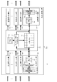
- FIG. 1 is a diagram schematically showing a configuration of a switch chip (data transfer circuit) 100 provided in a switch (data transfer device, data output device) 2 as an example of an embodiment, and FIG. It is a figure which illustrates the structure of the network system 1 which has a switch provided with.
- the network system 1 illustrated in FIG. 2 includes a plurality of servers 3 and a plurality of switches (SW) 2. In the example shown in FIG. 2, seven servers 3 of servers # 00, # 01, and # 10 to # 14 and five switches 2 of switches # 01 to # 05 are provided.
- reference numerals # 00, # 01, and # 10 to # 14 are attached. Use.
- reference numeral # 01 to # 05 are attached when it is necessary to specify one of a plurality of switches, but reference numeral 2 is used to indicate any switch.
- the switch 2 transfers the input data by the frame transfer method.
- Each switch 2 supports data input / output at a plurality of transmission rates, and enables data input and data output at each transmission rate of 1 Gpbs, 10 Gbps, 40 Gbps, and 100 Gbps, for example.
- a frame (first frame) transmitted at a transmission rate of 10 Gbps (first transmission rate) and a frame (first transmission rate) transmitted at a transmission rate of 100 Gbps (second transmission rate) An example in which frames of two types of transmission rates (second frame) are mixed is shown.
- the maximum speed (maximum transmission speed) of 100 Gbps that is, the maximum value of the data transfer rate in the network system 1 is 100 Gbps.
- the network system 1 is not limited to the mixed speed of 100 Gbps and 10 Gbps, but can be implemented with various modifications.
- the specific speed is 100 Gbps and 10 Gbps for easy understanding. Will be described.
- data transmitted at a transmission rate of 10 Gbps is simply referred to as 10 Gbps data or 10 G frame.
- data transmitted at a transmission rate of 100 Gbps is simply referred to as 100 Gbps data or 100 G frame.
- data (frames) transmitted from the servers # 00 and # 01 are transferred to any of the servers # 10 to # 14 via the plurality of switches 2.
- An example is shown.
- the left side in the figure, that is, the servers # 00 and # 01 side may be referred to as the upstream side
- the right side in the figure, that is, the servers # 10 to # 14 side may be referred to as the downstream side.
- the servers # 00 and # 01 and the switches # 02 and # 03 are connected to the switch # 01.
- Switches # 01 and # 04 are connected to the switch # 02, and switches # 01 and # 05 are connected to the switch # 03, respectively.
- Servers # 10 and # 11 and switch # 02 are connected to switch # 04.
- Servers # 12, # 13, # 14 and switch # 03 are connected to switch # 05.
- the switch 2 to which the server 3 is connected may be referred to as an edge switch 2.
- the switch 2 arranged between the switches 2 and connected to the server 3 via another switch 2 may be referred to as a next-stage switch 2.
- the switches # 01, # 04, and # 05 are the edge switches 2
- the switches # 02 and # 03 are the next stage switches 2.
- the maximum values of the data transfer rates supported by the interfaces of the servers # 00, # 10, # 12, and # 13 are 10 Gbps, respectively, and the servers # 01, # 11, and # 14
- the maximum data transfer rate supported by the interface is 100 Gbps each.
- Between server # 00 and switch # 01, between switch # 01 and switch # 02, between switch # 04 and server # 10, between switch # 05 and server # 12, and between switch # 05 and server The throughput of each transmission line with # 13 is 10 Gbps.
- a range (area) with a throughput of 100 Gbps is referred to as a maximum speed transmission area, and is surrounded by a dotted line and indicated by a symbol a in FIG.
- Each switch 2 has the same configuration, and includes the switch chip 100 shown in FIG. That is, the function as each switch 2 is realized by various settings of the switch chip 100.
- the edge switches # 01, # 04, and # 05 are set for the edge portion in the network system 1 configured by a switch group, and the next-stage switches # 02 and # 03 are set for other switches in the system.
- Settings for connecting the switch chip 100 are performed.
- the ports for the edge that is, the ports connected to the server 3 (server side and upstream side) are supported by the interface of the connected server 3. It is set according to the speed.
- each port (switch chip side, downstream side) connected to the other switch 2 in the switches # 01, # 04, and # 05 is fixed to 100 Gbps which is the upper limit in the specification of the network system 1. Is set.
- the ports on the server # 00 and # 01 side match the speed supported by the interface of the server 3 connected via the switch # 01.
- the switch chip side (downstream side) of the switches # 02 and # 03 is set to be fixed at 100 Gbps, which is the upper limit in the specifications of the network system 1.
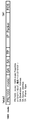
- FIGS. 3 and 4 are diagrams illustrating the configuration of a frame transferred in the network system 1 including the switch 2 as an example of the embodiment.
- FIG. 3 illustrates a 10G mode frame
- FIG. It is a figure which illustrates the frame of a mode.
- FIGS. 3 and 4 In the present storage system 1, the frames shown in FIGS. 3 and 4 are transferred. In FIGS. 3 and 4, the left side is the head of the frame, and the right side is the tail of the frame.
- a 10G mode frame (10G mode frame) is a frame created to pass through a 10 Gbps transmission path.
- a 100G mode frame is a frame created to pass through a 100 Gbps transmission path.
- the 10G mode frame and the 100G mode frame include fields of PR, DA, SA, TP, IP packet (IP Packet), and FCS, respectively.
- the field “PR (Preamble)” includes an 8-byte data storage area, for example.
- 7-byte information indicating the head of data is stored. Specifically, 7-byte data configured by repeating 7 consecutive 1-byte data (10101010) repeating 0 and 1 is stored as information indicating the head of the data.
- 1-byte identification information (data transmission rate information) indicating the transmission rate of the frame is stored in the field “PR”. That is, the data transmission rate information indicates whether the frame is a 10G mode frame or a 100G mode frame.
- 8′b01011011 that is, 1 byte (8 bits) information having a pattern of “01011011” is set as data transmission rate information.
- 8′b01101011 that is, 1 byte (8 bits) information having a pattern of “01101011” is set as data transmission rate information.
- This data transmission rate information is provided following the 7-byte information indicating the head of the data described above.
- 1-byte data transmission rate information (“01011011” or “01101011”) is stored at the trailing end of 01 of 7 bytes indicating the head of data.
- the data transmission rate information of the field “PR” in these 10G mode frame and 100G mode frame is added by the MAC 33 of the switch 2 connected to the server 3 that is the data transmission source in the network system 1, for example.
- the maximum value of the data transfer rate supported by the interface of the server # 00 that is the frame transmission source is 10 Gbps.
- 8'b01011011 is set as data transmission rate information in the PR of the frame received from 00.
- the frame output from the server # 00 becomes a 10G mode frame.
- the switch # 01 on the downstream side sets the PR of the frame received from the server # 01. 8'b01101011 is set as the data transmission rate information.
- the frame output from the server # 01 becomes a 100G mode frame.
- the speed of the interface is determined in the link-up process, and is realized by, for example, an auto-negotiation function. The determination of the interface speed can be realized by using various known methods, and detailed description thereof will be omitted.
- the field “DA” stores information indicating the destination of the frame (Destination Address), and the field “SA” stores information indicating the transmission source of the frame (Source Address).
- the field “TA” stores information indicating the type of the frame, and the field “IP Packet” stores data to be transferred (IP packet).
- the field “FCS” stores data error check data.
- the switch chip 100 includes n (n is a natural number) input ports 20, m (m is a natural number) output ports 30, and a control unit 10.
- the switch chip 100 is configured to be able to input 10 Gbps and 100 Gbps frames, and to be able to output 10 Gbps and 100 Gbps frames. In other words, frame transfer can be performed with all combinations of 10 Gbps and 100 Gbps inputs and 10 Gbps and 100 Gbps outputs.
- Data are input to the input port 20 from a server or another switch.
- reference numerals # 1 to #n are given when it is necessary to specify one of a plurality of input ports, but reference numeral 20 is used to indicate any input port.
- Each input port 20 has the same configuration. In FIG. 1, for convenience, only the configuration of the input port # 0 is shown, and the configuration of the other input ports 20 is not shown.
- the input port 20 includes a PMA (Physical Medium Attachment) / PMD (Physical Medium Dependent) 21, a PCS (Physical Coding Sublayer) 22, a MAC (Media Access Control) 23, and a frame parser (Frame Parser) 24. And an input buffer (IBuf) 25.
- PMA Physical Medium Attachment
- PMD Physical Medium Dependent
- PCS Physical Coding Sublayer
- MAC Media Access Control
- Frame Parser Frame Parser
- IBuf input buffer
- the PMA / PMD 21 and the PCS 22 perform processing of a PHY (Physical layer) layer (physical layer), which is the first layer of the OSI (Open System Interconnection) 7 layer. That is, PMA / PMD 21 performs serial / parallel conversion and signal waveform conversion, and PCS 22 performs frame coding.
- the PMA / PMD 21 directly connected to the transmission path transmits the data received at the input port 2 as a digital signal inside the switch chip 100.
- the MAC 23 recreates the MAC frame.
- the PCS 22 decodes the data sent after being encoded, and the MAC 23 regenerates the MAC frame. For example, in the case of a 100G mode frame, the MAC 23 transfers the data as it is. In the case of a 10G mode frame, the MAC 23 thins out the data to 1/10 and transfers it within the switch chip 100. At this time, data is stored and transferred in the width of an internal bus (not shown). That is, the transfer is performed at the usage rate of 1/10 internal bus at the time of transfer of the 100G mode frame.
- the frame parser 24 decodes the frame created by the MAC 23. Information and data decoded by the frame parser 24 are stored in the input buffer 25.
- the frame parser 24 functions as a reading unit that reads out data transmission rate information included in reception data input from the first communication path to which the input port 20 is connected. Data stored in the input buffer 25 is sequentially written into the shared memory 11 of the control unit 10.
- the input port 20 writes the frame data of the received frame to the shared memory 11.
- the control unit 10 includes a shared memory 11, a frame / memory controller 12, and a table (TBL) 13.
- the shared memory 11 is a storage device that stores data input to each input port 20.
- the frame / memory controller 12 controls writing of data to the shared memory 11 by the input port 20 and reading of data from the shared memory 11 from the output port 30 described later.
- the frame / memory controller 12 stores the data in the shared memory 11 and simultaneously notifies the output buffer 30 of the request.
- the destination information of the frame and the output port 30 are recorded in association with each other, and the frame / memory controller 12 outputs the output destination of the frame to be transferred based on the destination information recorded in the table 13.
- the output port 30 is determined. Further, the frame / memory controller 12 notifies the determined output port 30 of a frame transfer request (hereinafter simply referred to as a request).
- the blurred data is stored in the shared memory 11, and the frame / memory controller 12 stores all the data constituting the frame in the shared memory 11.
- the request selector 352 is sequentially notified without waiting for the data to be stored.
- the request selector 352 sequentially reads the frames transferred from the shared memory 11 and stores them in the data buffer 354. That is, in this switch 2, data transfer is performed by the CT method (data non-retention transfer method) that sequentially outputs the received frame data without waiting for the output until all the data of the frame is completed.
- the output port 30 reads data from the shared memory 11 and outputs data (packets) to the server and other switches.
- reference numerals # 1 to #m are used when one of a plurality of output ports needs to be specified, but reference numeral 30 is used to indicate an arbitrary output port.
- Each output port 30 has the same configuration. In FIG. 1, for convenience, only the configuration of the output port # 0 is shown, and the configuration of the other output ports 30 is not shown.
- Either a transmission line with a throughput of 10 Gbps or a transmission line with a throughput of 100 Gbps can be connected to the output port 30, and both a 10G mode frame and a 100G mode frame can be output.
- a number of requests for output may be accumulated in the output port 30 in some cases.
- the output port 30 when a 100G mode frame is output through a 100 Gbps transmission path, the frame is transmitted using all bands, and when a 10 G mode frame is transmitted through a 100 Gbps transmission path, a maximum of 10 frames are transmitted. Multiplex and transmit.
- the output port 30 includes a PMA (Physical Medium Attachment) / PMD (Physical Medium Dependent) 31, a PCS (Physical Coding Sublayer) 32, a MAC (Media Access Control) 33, and an output buffer (OBuf) 35. Prepare.
- PMA Physical Medium Attachment
- PMD Physical Medium Dependent
- PCS Physical Coding Sublayer
- MAC Media Access Control
- FIG. 5 is a diagram illustrating a configuration of the output buffer 35 in the switch 2 as an example of the embodiment.
- the output buffer 35 includes a timer 351, a request selector 352, a request buffer 353, a data buffer 354, an AND circuit 355, and a mode register 356.
- the timer 351 measures time according to an instruction from the request selector 352. In addition, the timer 351 notifies the request selector 352 of the measured time. The timer 351 also resets the time according to the instruction from the request selector 352.
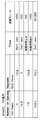
- the mode register 356 is a storage device that stores mode setting values. The mode setting value indicates a selected transfer mode from among transfer modes 1 to 3 described later. That is, any one of modes 1 to 3 is set in the mode register 356 in advance.
- mode register 356 for example, “00” is set when mode 1 is set, “01” is set when mode 2 is set, and “mode” is set when mode 3 is set. “11” is stored.
- the transfer mode will be described later with reference to FIGS. It is desirable that the mode setting value of the mode register 356 can be arbitrarily set by a system administrator or the like.
- the request buffer 353 stores a request (transfer request) notified from the frame / memory controller 12.
- the request notified from the frame / memory controller 12 of the control unit 10 described above is stored in the request buffer 353.
- Data read from the shared memory 11 is stored in the data buffer 354.
- the storage position of data read from the shared memory 11 is also designated by the request selector 352 and the request buffer 353.
- the AND circuit 355 receives an output signal from the data buffer 354 and a signal obtained by inverting the output signal from the MAC 33, and inputs an ANDed signal to the MAC 33. Thereby, when the output from the MAC 33 is completed, the next input is performed to the MAC 33.
- the request selector 352 selects a request to be executed from the requests stored in the request buffer 353.
- the request selector 352 selects a request to be executed from among the requests stored in the request buffer 353 in accordance with an instruction from the frame / memory controller 12, and stores the frame transferred from the shared memory 11 in the read data buffer 354. .
- the request selector 352 when outputting a 100 G mode frame at a rate of 100 Gbps, the request selector 352 reads a frame to be transferred from the shared memory 11 and stores it in the data buffer 354. When outputting a 10G mode frame at a rate of 100 Gbps, the request selector 352 causes the 10G mode frame to be transferred to be read from the shared memory 11 at a period 10 times that of reading the 100G mode frame, The data is stored in the data buffer 354.
- the request selector 352 when the output destination of the frame input from the plurality of input ports 20 is the output port 30 fixed to a common 100 Gbps, the request selector 352 The 10G mode frames from the plurality of input ports 20 are read out and stored in the data buffer 354, respectively. In this way, the request selector 352 creates a mixed frame obtained by mixing a plurality of 10G mode frames in the data buffer 354.
- the request selector 352 functions as a mixed data generating unit that generates a mixed frame (mixed data), and also functions as a multiplexing processing unit that generates a multiplexed frame by multiplexing a plurality of 10 mode frames.
- FIG. 6 is a diagram illustrating a mixed frame creation method in the switch 2 as an example of the embodiment
- FIG. 7 is a diagram illustrating the transfer method.
- the switch 2 shown in FIG. 6 corresponds to the switch # 01 of FIG.
- 10G mode frames are input to the input ports # 1 to # 3 of the switch 2 at a transmission rate of 10 Gbps, respectively, and these 10G mode frames are output from the common output port # 4 having a fixed transmission rate of 100 Gbps.
- An example is shown. Specifically, 10G mode frames F1 and F4 are sequentially input to the input port # 1. Similarly, 10G mode frames F2 and F5 are sequentially input to input port # 2, and 10G mode frames F3 and F6 are sequentially input to input port # 3.
- the request selector 352 of the switch chip 100 is input to the plurality of input ports 20.
- a mixed frame (F01, F02) is created by mixing the frames.
- the output port 30 uses a 100 Gbps frame transfer mechanism and inserts three 10 Gbps frames (for example, F1 to F3) respectively input from the three input ports 20 into a 100 Gbps frame (for example, F01). .
- three 10 Gbps frames respectively input from the three input ports 20 are overlapped (mixed) in a 100 Gbps frame (for example, F01).
- the output port 30 transfers data using the 30% bandwidth in the 100 Gbps frame transfer mechanism.
- the rectangles included in each frame on the input side and the output side indicate data, and one rectangle indicates one unit of data.
- One rectangle (data) has a data size of 8 bytes, for example.
- the codes F1 to F6 attached to the input side frame indicate the same data as the codes F1 to F6 attached to the output side data frame.
- Each of these frames F1 to F6 has a fixed size (for example, 8 bytes) as described above.
- 10 Gbps frames F1, F2, and F3 are included in one 100 Gbps frame F01.
- 10 Gbps frames F4, F5, and F6 are included in the 100 Gbps frame F02 output next to the frame F01.
- frames input from each input port 20 are transferred at regular intervals.
- the data F1 and F4 of the 10 Gbps input port # 1 are transferred at regular intervals (for example, 6.4 ns) from the 100 Gbps output port # 4.
- a number of received data within this ratio is mixed at the output port 30 to create a mixed frame.
- the request selector 352 When receiving a frame at the input port 20, the request selector 352 immediately transfers the frame to the output port 30 via the shared memory 11.
- the switch 2 when a frame is received at the input port 20, the frame is immediately transferred to the output port 30 via the shared memory 11. Further, the output port 30 multiplexes a plurality of inputted low speed (for example, 10 Gbps) frames and outputs them from a high speed interface. As a result, even when a frame input at 10 Gbps is output at 100 Gbps, frame transfer using the CT method is realized as shown in FIG.
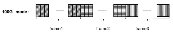
- FIG. 8 to FIG. 10 are diagrams showing frame states in the transmission path of the network system 1 including the switch 2 as an example of the embodiment.
- 8 is a diagram showing a 10G mode frame in a 100 Gbps transmission path
- FIG. 9 is a diagram showing a 100 G frame in a 100 Gbps transmission path
- FIG. 10 is a diagram in which 10 G frames and 100 G frames are mixed in a 100 Gbps transmission path. It is a figure which shows the example which transmits.
- each rectangle indicates a 10G frame, and a state (10G mode) in which a plurality of 10G frames are multiplexed and transferred in a 100 Gbps transmission path. That is, 10G frames are multiplexed and transferred to 100G.
- FIG. 9 shows a state (100G mode) in which a 100 G frame is transferred on a 100 Gbps transmission path. Each 100G frame has a data size corresponding to 10 10G frames. In this 100G mode, data is sent using 100% of the transmission capacity of a 100 Gbps transmission line.
- each rectangle represents data, and one rectangle represents one unit of data.
- One rectangle (data) has a data size of 8 bytes, for example.
- 10G mode data and 100G mode data cannot be mixed and transmitted. Therefore, as shown in FIG. 10, by transmitting the frame of the other mode after the transmission of the frame of one mode is completed, the 100G mode frame and the 10G mode frame are switched and transferred.
- FIG. 11 is a diagram illustrating a frame selection algorithm in mode 1 (100G priority) in the switch 2 as an example of the embodiment
- FIG. 12 is a diagram illustrating a frame selection algorithm in the mode 2 (10G priority).
- a 100G mode frame is transferred with priority over a 10G mode frame. That is, as shown in FIG. 11, in principle, if the number of 100G mode frames is greater than or equal to the first predetermined number (for example, one), the 10G mode frame is put in a transfer waiting state, the transfer is suppressed, and the 100G mode frame is transferred. .
- the first predetermined number for example, one
- the 10G mode frame is transferred.
- the 10G mode frame is also transferred when a predetermined number (eg, 10) or more of 10G mode frames are accumulated.
- the 10G mode frame is transferred with priority over the 100G mode frame. That is, as shown in FIG. 12, in principle, if there are more than a second predetermined number (for example, one) of 10G mode frames, the 100G mode frames are put in a transfer waiting state, the transfer is suppressed, and the 10G mode frames are transferred. .
- mode 1 and mode 2 are switched at a constant cycle. Continuing mode 1 or mode 2 may cause either 100 G mode frame or 10 G mode frame to stay excessively in switch 2. Therefore, by periodically switching between mode 1 and mode 2 at a constant cycle, it is possible to prevent either the 100G mode frame or the 10G mode frame from staying in the switch 2.
- Which of the modes 1 to 3 is adopted as the frame selection algorithm is registered in advance in the mode register 356 in the output port 30, for example, and the request selector 352 reads out the value of the mode register 356, and the modes 1 to 3 are selected. Select one of the following. Then, the request selector 352 selects a frame to be transmitted in the request buffer 353 according to the selected mode.
- the first and second predetermined numbers and the first and second predetermined times can be implemented with various modifications. Further, it is desirable to set a value for specifying the first and second predetermined numbers and the first and second predetermined times in a register or the like and to change the values.
- This example provides a method in which a 10G mode frame and a 100G mode frame can be output without much waiting. The algorithm for determining the frame to be output from the number of 10G mode frames and 100G mode frames will be described, and the individual number and algorithm are not limited.
- the first and second predetermined numbers setting a value obtained by dividing the maximum transfer rate in the switch chip 100 by the minimum transfer rate (maximum transfer rate / minimum transfer rate) can effectively use the bus without waste. It is thought that.
- FIG. 13 and FIG. 14 are diagrams showing the operation as the next-stage switch of the switch 2 as an example of the embodiment.
- the switch 2 shown in FIGS. 13 and 14 corresponds to the switch # 03 shown in FIG.
- the input port 20 and the output port 30 each operate as a 100 Gbps interface.
- FIGS. 13 and 14 only a part of the plurality of input ports 20 and output ports 30 are shown for convenience.
- the switch # 03 when the switch chip 100 outputs a 10G mode frame group input from one input port 20 at a transmission rate of 100 Gbps at a transmission rate of 100 Gbps from one output port 30, FIG. Thus, the input data group is transferred as it is by the CT method.
- the switch # 03 when the switch # 03 outputs 10G mode frames F1 to F6 input from one input port 20 at a transmission rate of 100 Gbps at three transmission ports 30 at a transmission rate of 100 Gbps, the switch # 03 As shown in FIG. 14, the chip 100 transfers back to the 10G mode frame at each output port 30.
- FIG. 15 is a diagram illustrating the operation of the switch 2 as an example of the embodiment. Note that the switch 2 illustrated in FIG. 15 corresponds to the switch # 05 illustrated in FIG. However, in the example shown in FIG. 15, it is assumed that each of the three output ports 30 of the switch 2 outputs at a transmission rate of 10 Gbps. In the switch # 05, the input port 20 operates as a 100 Gbps interface, and the plurality of output ports 30 each operate as a 10 Gbps interface. In FIG. 15, only a part of the plurality of input ports 20 and output ports 30 are shown for convenience.
- the switch chip 100 receives 10G mode frames F1 to F6 input at a transmission rate of 100 Gbps from one input port 20 from the three output ports 30 respectively. Output at the transmission speed.
- (B) Operation The processing of the switch chip 100 in the network system 1 as an example of the embodiment configured as described above will be described with reference to FIG.
- each input port 20 receives three 10G mode frames at a transmission rate of 100 Gbps and three 100G mode frames at a transmission rate of 100 Gbps.
- the received six frames are transmitted after determining the order of transmission at the output port 30 of the output destination and performing processing such as multiplexing.
- the frame parser 24 checks whether the frame received at 100 Gbps is a 100G mode frame or a 10G mode frame.
- the frame parser 24 uses, for example, a frame input to the input port 20 based on the interface speed determined at the time of link-up as a 100G mode frame. Or a 10G mode frame.
- the frame parser 24 determines whether the frame is a 100G mode frame or a 10G mode frame based on the data transmission rate information. You may judge.
- the frame parser 24 refers to the data transmission rate information included in the PR of the received frame, so that the frame is in the 100G mode. Whether it is a frame or a 10G mode frame can be determined. Since PR data is not necessary as original information, transmission to the inside of the chip is unnecessary, but the speed information is transmitted from the MAC 23 to the frame parser 24.
- the frame parser 24 recognizes the received frame as a 10G mode frame, only a portion where actual data exists is extracted and written to the shared memory 11 via the input buffer 25.
- data is continuously stored in the shared memory 11 via the input buffer 25.
- information such as a transmission destination necessary for transferring the data is sent to the frame / memory controller 12.
- the frame / memory controller 12 confirms the data and refers to the table 13 to determine from which output port 30 the data of the destination information is transmitted.
- the frame / memory controller 12 After determining the output port 30, the frame / memory controller 12 passes the information to the output port 30. Thereby, the output port 30 understands what data it should transmit.
- the output port 30 determines which of the 10G mode frame and the 100G mode frame is to be transmitted according to any one of the frame selection algorithms of modes 1 to 3, and transmits the frame according to this determination.
- the output port 30 receives information about a frame transmitted from the frame / memory controller 12.
- Information (request information) received from the frame / memory controller 12 is sequentially stored in the request buffer 353.
- the request selector 352 selects one of the modes 1 to 3 according to the set value of the mode register 356, and determines a request to be transmitted according to a frame selection algorithm corresponding to the selected mode.
- the request selector 352 and the request buffer 353 select the corresponding data, and extract the respective data from the shared memory 11 for each predetermined unit in order and multiplex them to the data buffer 354. Store. As a result, a mixed frame (see FIG. 8) is created in the data buffer 354.
- the timing for storing data in the data buffer 354 is adjusted using a known method such as a frame editor. Thereafter, the data is sent to the MAC 33 and sent by the known method via the PCS 32 and the PMA / PMD 31.
- the request selector 352 and the request buffer 353 sequentially connect the three 100G mode frames one by one (see FIG. 9), and transmit them to the MAC 33.
- the output port 30 if the data transmission rate information is not stored in the PR of the frame, the data transmission rate information is inserted into the PR of the frame in the MAC 33.
- the MAC 33 determines the data transmission rate information based on information from which input port 20 the frame is received, and sets it to PR.
- the input port 20 and the output port 30 are all described as having a speed of 100 Gbps.
- the present invention is not limited to this, and various modifications are made. be able to.
- the speeds of the input port 20 and the output port 30 may be appropriately controlled so as to match the configuration and setting. That is, a mixed frame is created at the output port 30 in accordance with the speed difference between the frame input to the input port 20 and the frame output from the output port 30.
- the switch chip 100 detects data reception by finding the PR of the input frame.
- the MAC 23 when the frame data is 100 Gbps, the data is transferred as it is.
- the data is thinned out to 1/10 and transferred within the switch chip 100.
- the data is stored in the width of the internal bus and transferred. That is, transfer is performed with the usage rate of the internal bus of the normal switch chip 100 being 1/10.
- the frame data is transferred to the shared memory 11.
- Data used for frame transfer such as DA is sent to the frame / memory controller 12.
- the frame / memory controller 12 determines an output port 30 to which data is transferred, and instructs writing to the shared memo 11. You are now ready to transfer data.
- the frame / memory controller 12 stores the data in the shared memory 11, it notifies the output buffer 30 of the request.
- the notified request is stored in the request buffer 353, and a request to be transmitted is determined by the request selector 352 and the timer 351 according to the frame selection algorithm described above.
- the determined requests are sequentially read from the shared memory 11 and stored in the data buffer 354. That is, the output port 30 reads data. At this time, since each input data is transferred to the output port 30 in the output port 30, many requests for output are accumulated in the output port 30 depending on the case.
- the output buffer 35 data is read from the shared memory 11 in accordance with an instruction from the request selector 352 and stored in the data buffer 354, thereby generating mixed data in the data buffer 354.
- the output port 30 when a 100G mode frame is output, one frame occupies the entire band.
- a 10G mode frame is transmitted, a maximum of 10 frames are multiplexed and transmitted. In other words, the 10G mode frame is read at a cycle 10 times that of reading the 100G mode frame and stored in the data buffer 354.
- the request selector 352 reads the value of a register (not shown) and selects any one of modes 1 to 3 according to the value of this register. Then, the request selector 352 selects a frame to be transmitted in the request buffer 353 according to the selected mode. The data stored in the data buffer 354 is transmitted to the MAC 33 as soon as a transmission port (not shown) is ready. At this time, when editing a frame, for example, setting data transmission speed information in the PR of the frame, the processing is performed using, for example, a frame editor.
- step S1 the request selector 352 refers to, for example, the request buffer 353 and determines whether there is a request to be transmitted. If there is no request (refer to the NO route in step S1), step S1 is repeated to wait for a request.
- step S5 If there is no 10G mode frame request (see YES route in step S4), in step S5, the oldest data in the 100G mode frame transfer request (100G request: 100Gbps Request) is transmitted to the MAC 33, and the process is performed. finish. On the other hand, if the 10G request exists as data to be transmitted (see NO route in step S4), then in step S6, there are one or more and 9 or less 10G requests, and one It is confirmed whether or not the above 100G request exists. That is, the operation is changed depending on the number of 10 requests and 100G requests.
- the request selector 352 selects the timer 351 in step S7. To check if it is running.
- the request selector 352 instructs the timer 351 to start timing in step S8. The timer 351 starts timing according to this instruction.
- step S7 If the timer 351 has already been started and time is being measured (see YES route in step S7), the request selector 352 exceeds the predetermined time in the time measured by the timer 351 in step S9 (see FIG. Check if the timer is over. If timer over is not detected (see NO route in step S9), in step S11, the oldest data in the 100G request is transmitted to the MAC 33, and the process ends.
- step S9 may be skipped and it may transfer to step S11 directly from step S8.
- step S10 the oldest data in the 10G request is transmitted to the MAC 33 in order. If the timer is over, a 10G mode frame is preferentially transmitted because the 10G request has been held for a long time. It is desirable that the value of the timer 351 can be set in a register in the switch chip that can be changed after hardware design. Thereafter, the process ends.
- step S6 when one or more and 9 or less 10G requests exist and the condition that one or more 100G requests exist (see the NO route in step S6), in step S12, it is confirmed whether there are 10 or more 10G requests and one or more 100G requests. If there are 10 or more 10G requests and one or more 100G requests (see YES route in step S12), either a 10G mode frame or a 100G mode frame is transmitted in step S13. Which frame is to be transmitted may be determined by hardware, or may be set by a register in the switch chip.
- step S12 if the condition that there are 10 or more 10G requests and one or more 100G requests is not satisfied (see the NO route in step S12), this is an abnormal state that is not possible. Therefore, in step S14, the request selector 352 records a flag indicating that an error has occurred in an error flag set in a register area (not shown) in the switch chip 100, and ends the processing.
- FIG. 17 is a flowchart (steps S1 to S5, S61, S7 to S9, S101, S111, S12 to S14) for explaining a frame transmission method in mode 2 by the output buffer 35 of the switch 2 as an example of the embodiment.
- the flowchart shown in FIG. 17 includes S101 and S111 instead of S10 and S11 in the flowchart shown in FIG.
- the description is abbreviate
- step S9 if timer over is not detected (see NO route in step S9), in step S111, the oldest data in the 10G request is transmitted to the MAC 33 in order, and the process is terminated. If a timer over is detected (see YES route in step S9), the oldest data in the 100G request is transmitted to the MAC 33 in step S101.
- the switch 2 performs data transfer by the CT method of sequentially outputting the received frame data without waiting for the output until all the data of the frame is completed. As a result, it is not necessary to perform a data store that causes an increase in latency, and low latency and high throughput can be realized.
- the time required for the data store required in the ST method can be reduced and the latency can be shortened. It is possible.
- the low-speed reception data from the plurality of input ports 20 is inserted into the gaps by mixing (multiplexing) the low-speed reception data input from the plurality of input ports 20.
- data can be transmitted continuously without a gap.
- the 100 Gbps frame uses 100% of the bandwidth of the 100 Gbps transmission path. Forward.
- a 10 Gbps frame is transferred utilizing a 10% bandwidth of a 100 Gbps transmission path. At 10 Gbps, only 10% of the bandwidth is used. Therefore, the data store that causes an increase in latency can be reduced by transferring the 10 Gbps frame with a maximum of 10 frames.
- the mixed frame is created by mixing (superposing) the frame data in a certain amount in the order of arrival in the output buffer 35.
- the frames when frames of a plurality of speeds are transferred in the switch 2, the frames can be efficiently transferred with low latency without lowering the throughput. This can be realized with lower latency while maintaining the above.
- the maximum transmission area that is the core of the network system 1, since the transfer is performed at the maximum speed of the switch chip 100, the setting of the network system 1 is simplified. Also, the same cable can be used in that area, and the cost for constructing the network system 1 can be reduced.
- FIG. 18 is a diagram illustrating a first modification of the network system 1 including the switch 2 as an example of the embodiment.
- the data transmission rate information of the field “PR” in the 10G mode frame and the 100G mode frame is set in each server 3. That is, the server 3 also mixes speeds of 100 Gbps and 10 Gbps.
- the maximum speed transmission area a in the network system 1 can be widened, whereby the data flow in the network system 1 can be further optimized.
- An output port (not shown) of the server (data output device) 3 has the same function as the output port 30 of the switch chip 100 described above.
- the server 3 generates a multiplexed frame by multiplexing frames of the first transmission rate (for example, 10 Gbps), and uses the multiplexed frame as a second transmission rate that is faster than the first transmission rate.
- the data can be output from a communication path that can be transmitted at (eg, 100 Gbps).
- FIG. 19 is a diagram illustrating a second modification of the network system 1 including the switch 2 as an example of the embodiment.
- the case where all the ports 20 and 30 have a speed of 100 G has been described.
- the speeds of the input port and the output port may be controlled to match the configuration and setting.
- the network system 1 shown in FIG. 19 includes a switch_0 (SW_0) instead of the switch # 04 in the network system 1 shown in FIG.
- the switch_0 supports only 10 Gbps, which is a low transmission rate, and includes a switch chip that does not support a transmission rate of 100 Gbps. In this way, in the network system 1, it is possible to mix switches 2 that support only 10 Gbps, which is a low transmission rate.
- the switch_0 is excluded from the maximum speed transmission area a, and the boundary with the maximum speed transmission area a is between SW_O and the SW group.
- the configuration of the network system 1 is not limited to the configuration illustrated in FIGS. 2, 18 and 19, and can be implemented with appropriate modifications.
- the number of servers 3, edge switches 2, and next-stage switches 2 can be changed as appropriate.
- the two types of transmission rate frames ie, the 10G mode frame and the 100G mode frame are exemplified, but the present invention is not limited to this. That is, it may be a frame with a transmission rate other than 10G or 100G, or a mixture of frames with three or more types of transmission rates.
- the request buffer 353 is provided in the output buffer 35, but is not limited thereto, and may be in the frame / memory controller 12, for example.
- the processor and the storage device are provided, and the processor executes the program stored in the storage device, thereby realizing the functions as the request selector 352 and the timer 351 described above. May be.
Landscapes
- Engineering & Computer Science (AREA)
- Quality & Reliability (AREA)
- Computer Networks & Wireless Communication (AREA)
- Signal Processing (AREA)
- Time-Division Multiplex Systems (AREA)
- Data Exchanges In Wide-Area Networks (AREA)
- Communication Control (AREA)
Abstract
L'invention concerne un dispositif de transfert de données qui est pourvu d'une unité de création de données mélangées (35) pour mélanger des données reçues, entrées par une pluralité de premiers chemins de communication, et pour créer des données mélangées lorsque la vitesse de transmission de données des données reçues, entrées par la pluralité de premiers chemins de communication, est inférieure à la valeur de rendement de transmission de données d'un second chemin de communication, et d'une unité de sortie (35) pour sortir les données mélangées, créées par l'unité de création de données mélangées (35) au second chemin de communication. Ainsi, il est possible d'améliorer l'efficacité de transfert des données.
Priority Applications (2)
| Application Number | Priority Date | Filing Date | Title |
|---|---|---|---|
| JP2015529289A JP6206497B2 (ja) | 2013-08-01 | 2013-08-01 | データ転送装置およびデータ転送方法 |
| PCT/JP2013/070922 WO2015015620A1 (fr) | 2013-08-01 | 2013-08-01 | Dispositif de transfert de données, dispositif de sortie de données, procédé de transfert de données et procédé de sortie de données |
Applications Claiming Priority (1)
| Application Number | Priority Date | Filing Date | Title |
|---|---|---|---|
| PCT/JP2013/070922 WO2015015620A1 (fr) | 2013-08-01 | 2013-08-01 | Dispositif de transfert de données, dispositif de sortie de données, procédé de transfert de données et procédé de sortie de données |
Publications (1)
| Publication Number | Publication Date |
|---|---|
| WO2015015620A1 true WO2015015620A1 (fr) | 2015-02-05 |
Family
ID=52431192
Family Applications (1)
| Application Number | Title | Priority Date | Filing Date |
|---|---|---|---|
| PCT/JP2013/070922 Ceased WO2015015620A1 (fr) | 2013-08-01 | 2013-08-01 | Dispositif de transfert de données, dispositif de sortie de données, procédé de transfert de données et procédé de sortie de données |
Country Status (2)
| Country | Link |
|---|---|
| JP (1) | JP6206497B2 (fr) |
| WO (1) | WO2015015620A1 (fr) |
Cited By (1)
| Publication number | Priority date | Publication date | Assignee | Title |
|---|---|---|---|---|
| CN108631873A (zh) * | 2017-03-21 | 2018-10-09 | 中兴通讯股份有限公司 | 网络管理信息的收发方法、装置、发送设备和接收设备 |
Citations (3)
| Publication number | Priority date | Publication date | Assignee | Title |
|---|---|---|---|---|
| JPS6188626A (ja) * | 1984-09-28 | 1986-05-06 | エヌ・ベー・フイリツプス・フルーイランペンフアブリケン | 時分割多重信号生成回路 |
| JPH0697904A (ja) * | 1992-09-14 | 1994-04-08 | Fujitsu Ltd | 通信回線多重使用方式 |
| JP2006157473A (ja) * | 2004-11-30 | 2006-06-15 | Nippon Hoso Kyokai <Nhk> | ストリーム多重化送出装置 |
Family Cites Families (3)
| Publication number | Priority date | Publication date | Assignee | Title |
|---|---|---|---|---|
| JPH05110537A (ja) * | 1991-10-15 | 1993-04-30 | Fujitsu Ltd | インテリジエント多重装置 |
| JP2001057527A (ja) * | 1999-08-18 | 2001-02-27 | Toshiba Corp | 通信方法および通信装置 |
| JP2013009089A (ja) * | 2011-06-23 | 2013-01-10 | Nec Corp | 送信側装置、受信側装置、中継装置、通信システム、送信方法、受信方法、送信および受信プログラム |
-
2013
- 2013-08-01 WO PCT/JP2013/070922 patent/WO2015015620A1/fr not_active Ceased
- 2013-08-01 JP JP2015529289A patent/JP6206497B2/ja active Active
Patent Citations (3)
| Publication number | Priority date | Publication date | Assignee | Title |
|---|---|---|---|---|
| JPS6188626A (ja) * | 1984-09-28 | 1986-05-06 | エヌ・ベー・フイリツプス・フルーイランペンフアブリケン | 時分割多重信号生成回路 |
| JPH0697904A (ja) * | 1992-09-14 | 1994-04-08 | Fujitsu Ltd | 通信回線多重使用方式 |
| JP2006157473A (ja) * | 2004-11-30 | 2006-06-15 | Nippon Hoso Kyokai <Nhk> | ストリーム多重化送出装置 |
Cited By (3)
| Publication number | Priority date | Publication date | Assignee | Title |
|---|---|---|---|---|
| CN108631873A (zh) * | 2017-03-21 | 2018-10-09 | 中兴通讯股份有限公司 | 网络管理信息的收发方法、装置、发送设备和接收设备 |
| JP2019534609A (ja) * | 2017-03-21 | 2019-11-28 | 中興通訊股▲ふん▼有限公司Ztecorporation | ネットワーク管理情報の受送信方法、装置、送信装置および受信装置 |
| CN108631873B (zh) * | 2017-03-21 | 2023-04-07 | 中兴通讯股份有限公司 | 网络管理信息的收发方法、装置、发送设备和接收设备 |
Also Published As
| Publication number | Publication date |
|---|---|
| JPWO2015015620A1 (ja) | 2017-03-02 |
| JP6206497B2 (ja) | 2017-10-04 |
Similar Documents
| Publication | Publication Date | Title |
|---|---|---|
| EP2898651B1 (fr) | Appareil réseau multiprotocole à latence réduite extensible | |
| CN101578794B (zh) | 数据通信装置及网络组件 | |
| US8837492B2 (en) | Multiplexed data stream circuit architecture | |
| JP6192803B2 (ja) | データのスケジューリングおよび交換の方法、装置、システム | |
| US20040100944A1 (en) | Serial ATA frame structure routing circuitry and protocols | |
| EP0535428B1 (fr) | Intégration de trafic synchrone et asynchrone dans des anneaux | |
| US11256634B2 (en) | System and method for serial interface memory using switched architecture | |
| JPH0732398B2 (ja) | バス・アクセス制御方法 | |
| US20070201471A1 (en) | Fabric channel control apparatus and method | |
| US9608935B2 (en) | Tunneling within a network-on-chip topology | |
| JP5332430B2 (ja) | 共有メモリシステム | |
| JP6206497B2 (ja) | データ転送装置およびデータ転送方法 | |
| US20120163398A1 (en) | Communication apparatus, relay apparatus, and network system | |
| CN103312577A (zh) | 一种处理mac数据的方法及装置 | |
| CN116346720B (zh) | 一种传输信息的装置和方法 | |
| CN117278507A (zh) | 一种缓存器、缓存器系统及数据处理方法 | |
| US8392733B2 (en) | Network apparatus | |
| US9154454B1 (en) | Fabric link physical coding sublayer packing scheme | |
| KR102834264B1 (ko) | 레가시 노드의 tsn 통신을 가능하게 하는 프로토콜 변환 장치 및 프로토콜 변환 방법 | |
| JP2009218778A (ja) | パケット伝送システム | |
| US9356873B2 (en) | Backbone channel management method and backbone channel management apparatus | |
| JP6752355B2 (ja) | 中継装置及びデータ転送方法 | |
| CN114500581B (zh) | 一种等延迟的分布式缓存以太网mac架构的实现方法 | |
| JP7696518B2 (ja) | 転送装置、転送方法、および転送プログラム | |
| KR101171463B1 (ko) | 신호 전달 제어 장치 및 그의 제어 방법 |
Legal Events
| Date | Code | Title | Description |
|---|---|---|---|
| 121 | Ep: the epo has been informed by wipo that ep was designated in this application |
Ref document number: 13890631 Country of ref document: EP Kind code of ref document: A1 |
|
| ENP | Entry into the national phase |
Ref document number: 2015529289 Country of ref document: JP Kind code of ref document: A |
|
| NENP | Non-entry into the national phase |
Ref country code: DE |
|
| 122 | Ep: pct application non-entry in european phase |
Ref document number: 13890631 Country of ref document: EP Kind code of ref document: A1 |