WO2015015794A1 - 電源機器判定装置、電源機器判定方法及び電力変換装置 - Google Patents
電源機器判定装置、電源機器判定方法及び電力変換装置 Download PDFInfo
- Publication number
- WO2015015794A1 WO2015015794A1 PCT/JP2014/003960 JP2014003960W WO2015015794A1 WO 2015015794 A1 WO2015015794 A1 WO 2015015794A1 JP 2014003960 W JP2014003960 W JP 2014003960W WO 2015015794 A1 WO2015015794 A1 WO 2015015794A1
- Authority
- WO
- WIPO (PCT)
- Prior art keywords
- power supply
- voltage
- power
- determination
- control unit
- Prior art date
- Legal status (The legal status is an assumption and is not a legal conclusion. Google has not performed a legal analysis and makes no representation as to the accuracy of the status listed.)
- Ceased
Links
Images


Classifications
-
- H—ELECTRICITY
- H02—GENERATION; CONVERSION OR DISTRIBUTION OF ELECTRIC POWER
- H02J—ELECTRIC POWER NETWORKS; CIRCUIT ARRANGEMENTS OR SYSTEMS FOR SUPPLYING OR DISTRIBUTING ELECTRIC POWER; SYSTEMS FOR STORING ELECTRIC ENERGY
- H02J1/00—Circuit arrangements for DC mains or DC distribution networks
- H02J1/10—Parallel operation of DC sources
- H02J1/12—Parallel operation of DC sources having power converters with further DC sources without power converters
-
- G—PHYSICS
- G01—MEASURING; TESTING
- G01R—MEASURING ELECTRIC VARIABLES; MEASURING MAGNETIC VARIABLES
- G01R21/00—Arrangements for measuring electric power or power factor
-
- H—ELECTRICITY
- H02—GENERATION; CONVERSION OR DISTRIBUTION OF ELECTRIC POWER
- H02J—ELECTRIC POWER NETWORKS; CIRCUIT ARRANGEMENTS OR SYSTEMS FOR SUPPLYING OR DISTRIBUTING ELECTRIC POWER; SYSTEMS FOR STORING ELECTRIC ENERGY
- H02J3/00—Circuit arrangements for AC mains or AC distribution networks
- H02J3/38—Arrangements for feeding a single network from two or more generators or sources in parallel; Arrangements for feeding already energised networks from additional generators or sources in parallel
-
- H—ELECTRICITY
- H02—GENERATION; CONVERSION OR DISTRIBUTION OF ELECTRIC POWER
- H02J—ELECTRIC POWER NETWORKS; CIRCUIT ARRANGEMENTS OR SYSTEMS FOR SUPPLYING OR DISTRIBUTING ELECTRIC POWER; SYSTEMS FOR STORING ELECTRIC ENERGY
- H02J7/00—Circuit arrangements for charging or discharging batteries or for supplying loads from batteries
- H02J7/34—Parallel operation in networks using both storage and other DC sources, e.g. providing buffering
- H02J7/35—Parallel operation in networks using both storage and other DC sources, e.g. providing buffering with light sensitive cells
-
- H—ELECTRICITY
- H02—GENERATION; CONVERSION OR DISTRIBUTION OF ELECTRIC POWER
- H02M—APPARATUS FOR CONVERSION BETWEEN AC AND AC, BETWEEN AC AND DC, OR BETWEEN DC AND DC, AND FOR USE WITH MAINS OR SIMILAR POWER SUPPLY SYSTEMS; CONVERSION OF DC OR AC INPUT POWER INTO SURGE OUTPUT POWER; CONTROL OR REGULATION THEREOF
- H02M7/00—Conversion of AC power input into DC power output; Conversion of DC power input into AC power output
- H02M7/42—Conversion of DC power input into AC power output without possibility of reversal
- H02M7/44—Conversion of DC power input into AC power output without possibility of reversal by static converters
-
- H—ELECTRICITY
- H02—GENERATION; CONVERSION OR DISTRIBUTION OF ELECTRIC POWER
- H02J—ELECTRIC POWER NETWORKS; CIRCUIT ARRANGEMENTS OR SYSTEMS FOR SUPPLYING OR DISTRIBUTING ELECTRIC POWER; SYSTEMS FOR STORING ELECTRIC ENERGY
- H02J2101/00—Supply or distribution of decentralised, dispersed or local electric power generation
- H02J2101/40—Hybrid power plants, i.e. a plurality of different generation technologies being operated at one power plant
-
- Y—GENERAL TAGGING OF NEW TECHNOLOGICAL DEVELOPMENTS; GENERAL TAGGING OF CROSS-SECTIONAL TECHNOLOGIES SPANNING OVER SEVERAL SECTIONS OF THE IPC; TECHNICAL SUBJECTS COVERED BY FORMER USPC CROSS-REFERENCE ART COLLECTIONS [XRACs] AND DIGESTS
- Y02—TECHNOLOGIES OR APPLICATIONS FOR MITIGATION OR ADAPTATION AGAINST CLIMATE CHANGE
- Y02E—REDUCTION OF GREENHOUSE GAS [GHG] EMISSIONS, RELATED TO ENERGY GENERATION, TRANSMISSION OR DISTRIBUTION
- Y02E10/00—Energy generation through renewable energy sources
- Y02E10/50—Photovoltaic [PV] energy
- Y02E10/56—Power conversion systems, e.g. maximum power point trackers
Definitions
- the present invention relates to a power supply device determination device for determining the type of power supply device, a power supply device determination method, and a power conversion device including them.
- a power control system it is required to centrally manage and operate a plurality of power supply devices such as solar cells, storage batteries, fuel cells, wind power generators and hydroelectric power generators.
- a DC link system has been proposed in which each power supply device is connected as it is with direct current power from the viewpoint of easy control, improved efficiency, cost reduction, and the like.
- This is a system in which power from a solar cell, a fuel cell, or the like is linked as it is DC power, charged directly into a storage battery, converted into AC power using one inverter, and supplied to a load.
- this DC link system since it is not necessary to convert the output for each power supply device with an inverter as in the prior art, there is little conversion loss and an improvement in efficiency can be expected. Further, according to the DC link system, the system is simplified and the cost can be reduced. Furthermore, since the DC link system links DC power, there is an advantage that power control becomes easy.
- the output voltage of a plurality of power supply devices connected to this DC link system is usually different for each device. Therefore, in order to configure the DC link system by connecting the outputs of these devices with direct current power, the outputs from the plurality of power supply devices must be boosted to the same voltage.
- the user individually checks the type of the connected power supply device and sets the DC / DC converter so as to boost the output voltage at a boost ratio corresponding to the type of the device. Had to do.
- An object of the present invention made in view of the above points is to provide a determination device for automatically determining a connected power supply device in a power conversion device employing a DC link.
- a determination device for a power supply device includes: A power device determination apparatus capable of connecting a plurality of power devices, A plurality of connection portions to which the plurality of power supply devices can be connected; A plurality of voltage converters connected in series to the plurality of connections; A voltage measurement unit for measuring each output voltage value after passing through the plurality of voltage conversion units; A control unit having means for determining the plurality of power supply devices based on a voltage measurement result by the voltage measurement unit when the voltage boosting ratios of the plurality of voltage conversion units are the same.
- control unit is configured to determine the plurality of power supply devices based on the voltage measurement result by the voltage measurement unit when the step-up ratios of the plurality of voltage conversion units are the same. It is preferable to switch between a steady operation mode for individually controlling the boost ratio of the voltage converter.
- control unit individually controls the boost ratios of the plurality of voltage conversion units based on the determination results of the plurality of power supply devices in the device determination mode.
- control unit individually controls the boost ratios of the plurality of voltage conversion units so that output voltages of the plurality of voltage conversion units in the steady operation mode are the same.
- control unit sets the connection switch to an OFF state in the device determination mode and sets the connection switch to an ON state in the steady operation mode.
- the determination of the plurality of power supply devices is identification of types of the plurality of power supply devices.
- the determination of the plurality of power supply devices is determination of an optimum step-up ratio of the plurality of power supply devices.
- a power conversion device includes: A power conversion device capable of connecting a plurality of power supply devices, A plurality of connection portions to which the plurality of power supply devices can be connected; A plurality of voltage converters connected in series to the plurality of connections; A voltage measurement unit for measuring each output voltage value after passing through the plurality of voltage conversion units; The device determination mode for determining the plurality of power supply devices and the step-up ratios of the plurality of voltage conversion units are individually determined based on the voltage measurement result by the voltage measurement unit when the step-up ratios of the plurality of voltage conversion units are the same. And a control unit that controls to switch the steady operation mode to be controlled.
- a method for determining a power supply device includes: A method for determining a power supply device capable of connecting a plurality of power supply devices, A first voltage conversion step of converting the output power of the plurality of power supply devices at the same step-up ratio; A voltage measurement step of measuring each output voltage value after passing through the voltage conversion unit converted into a voltage by the first voltage conversion step; And a determination step of determining the plurality of power supply devices based on each output voltage value measured in the voltage measurement step.
- a second voltage conversion step of individually controlling the boosting ratios of the plurality of voltage conversion units based on the determination information of the power supply device in the determination step.
- a power conversion device employing a DC link it is possible to automatically determine a plurality of connected power supply devices and control the output voltages after DC / DC conversion to be the same.
- FIG. 1 is a block diagram showing a configuration of a power conversion device 105 including a power device determination device 100 according to the first embodiment of the present invention.
- a power device determining apparatus 100 includes a power device connecting unit 101 for connecting a plurality of power devices, a voltage measuring unit 102 for measuring an output voltage from each power device, and each component. And a control unit 103 for controlling.
- the power converter device 105 is further provided with the load connection part 104 for connecting with load.
- the power supply device connection unit 101 includes power supply device connection terminals 2a to 2e for connecting the power supply devices 1a to 1e.
- the power supply device connection unit 101 further includes voltage converters 3a to 3e for performing DC / DC conversion on the electric power input from each power supply device. The electric power boosted or lowered by the voltage converter is output to the voltage measuring devices 4a to 4e in the voltage measuring unit 102.
- the power supply device connection terminals 2a to 2e are power terminals for inputting / outputting power between each power supply device and the power conversion device of the present invention, as well as control for the control unit 103 to control each power supply device.
- a signal terminal can be provided.
- power supply devices 1a to 1c solar cells
- a power supply device 1d fuel cell
- a power supply device 1e storage battery
- Solar cells convert solar energy into DC power.
- a solar cell is configured, for example, so that a large number of photoelectric conversion cells are connected in series, and a predetermined current is output when sunlight is irradiated.
- a silicon-based polycrystalline solar battery can be used as the solar battery connected to the power supply device connection terminals 2a to 2c.
- the solar cell is not limited to this, and any silicon-based single crystal solar cell or thin-film solar cell such as CIGS may be used as long as it is capable of photoelectric conversion, and the type of solar cell is not limited. Absent.
- a fuel cell uses hydrogen as a fuel to generate DC power through a chemical reaction with oxygen in the air.
- the fuel cell is classified into a solid oxide fuel cell (Solid Oxide Fuel Cell), a polymer electrolyte fuel cell (Polymer Electrolyte Fuel Cell) and the like depending on the substance used for the electrolyte.
- the type of the fuel cell is not particularly limited.
- a lithium ion battery can be used as the storage battery used in the present embodiment.
- Other types of storage batteries such as nickel metal hydride batteries can also be used.
- a single storage battery it is also possible to charge a storage battery mounted on an electric vehicle (EV) or a plug-in hybrid vehicle (PHV).
- EV electric vehicle
- PSV plug-in hybrid vehicle
- the power supply devices connected to the power supply device connection terminals 2a to 2e include solar cells, fuel cells, and storage batteries, and may include devices that rectify and output AC power, such as wind power generators and small hydraulic power generators. .
- the voltage converters 3a to 3e perform DC / DC conversion with respect to the output voltage of each power supply device at a predetermined step-up ratio based on the control signal 11 from the control unit 103.
- the step-up ratio refers to the ratio of the DC output voltage value to the DC input voltage value in each of the voltage converters 3a to 3e.
- the voltage measuring unit 102 includes voltage measuring devices 4a to 4e for measuring the voltage of the DC power output from the voltage converters 3a to 3e.
- the output voltages of the voltage converters 3a to 3e are measured by the individual voltage measuring devices 4a to 4e.
- the control unit 103 uses a control signal 11 shown in FIG. 1 to supply power devices 1a to 1e, voltage converters 3a to 3e, voltage measuring devices 4a to 4e, an inverter 6 in a load connection unit 104, which will be described later, switches 7a and 7b, It is comprised so that communication with the load 9 is possible, and various control of these components is possible.
- control unit 103 controls the ON / OFF of the power supply devices 1a to 1e, sets the step-up ratio of the voltage converters 3a to 3e, controls the voltage measuring devices 4a to 4e and reads the measured values, Setting, control of the switches 7a and 7b, ON / OFF control of the load 9, and the like are possible.
- control signal 11 for the control unit 103 to control each component is shown by a solid line in FIG. 1, but the transmission of the control signal may use wired communication. Wireless communication can also be used.
- the load connection unit 104 is not included in the power device determination apparatus 100 of the present invention, but is included in the power conversion apparatus 105 of the present invention.
- the load connection unit 104 includes an inverter 6 that converts DC power supplied from the voltage measurement unit 102, and a load connection terminal 8 a that connects the output of the inverter 6 to the load 9.
- the inverter 6 converts the electric power from the voltage measuring unit 102 into a single-phase three-wire AC 200V corresponding to the load 9.
- the electric power converted into AC 200V is supplied to the load 9 connected to the load connection terminal 8a.
- the inverter 6 Based on the control signal 11 from the control unit 103, the inverter 6 performs conversion to the optimum power corresponding to the load connected as described above.
- the load connection terminal 8 a can include a control signal terminal so that the control unit 103 can control the load 9 in addition to a power terminal for inputting and outputting power to and from the load 9.
- a load 9 that operates with single-phase three-wire AC 200V is connected to the load connection terminal 8a.
- the load 9 is an AC 100V drive load that draws and supplies two wires including a neutral phase among single-phase three wires of AC 200V.
- Examples of the load 9 include household appliances such as a dryer, a home game machine, or an audio system for listening to music, as well as electrical appliances such as a refrigerator, an emergency light, a hot water supply system, or a home network server that should avoid power outages as much as possible. For example, load.
- the power supply to the load 9 can be switched between the supply from the commercial power supply system 10 connected to the load connection terminal 8b and the supply from the inverter 6 by switching the switches 7a and 7b. Configure. This switching is performed based on the output voltage of the commercial power supply system 10 and the inverter 6 monitored by the control unit 103.
- the device determination mode for determining the type of the power supply device and the subsequent steady operation mode in the first embodiment will be individually described below.
- the voltage converters 3a to 3e in the power device connection unit 101 boost the output power of the power devices 1a to 1e with the same boost ratio.
- the output power of the power supply devices 1a to 1e is boosted sequentially at the same boost ratio 1.2, and the output power is input to the voltage measuring devices 4a to 4e.
- the boost ratio in this device determination mode can be set to any value between 1 and 2.
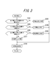
- FIG. 2 is a flowchart showing the procedure for determining the power supply device in the first embodiment.
- the control unit 103 of the power device determination apparatus 100 turns on the power supply devices 1a to 1e (step S101).
- the control unit 103 boosts only the output power of the power supply device 1a by the voltage converter 3a (step S102).
- the voltage converters 3b to 3e are not operated, and the input side of the inverter 6 of the voltage converters 3b to 3e is open. Accordingly, the outputs of the voltage converters 3b to 3e do not affect the output voltage of the voltage converter 3a and the measurement result of the voltage measuring device 4a.
- control unit 103 After boosting in step S102, the control unit 103 measures the boosted output voltage of the power supply device 1a by the voltage measuring device 4a (step S103). The control unit 103 determines the power supply device 1a based on the measurement result of the output voltage (step S104).
- FIG. 3 shows in detail a flowchart of the determination procedure of the power supply devices 1a to 1e in step S104.
- the control unit 103 determines whether the output voltage measurement result of the voltage converter 3a by the voltage measuring device 4a is within the predetermined range A shown in Table 1 (step S201). When the control unit 103 determines that the power source device 1a is within the predetermined range A, the power supply device 1a is determined to be a “solar cell” (step S202). The control unit 103 stores the determination result of the power supply device 1a in the storage unit 12 in the control unit 103 (step S208), and the determination ends.
- step S105 the control unit 103 boosts only the output power of the power supply device 1b by the voltage converter 3b (step S105).
- step S102 the voltage converters 3a and 3c to 3e are not operated, and the inverter 6 input side of the voltage converters 3a and 3c to 3e is open. Accordingly, the outputs of the voltage converters 3a and 3c to 3e do not affect the output voltage of the voltage converter 3b and the measurement result of the voltage measuring device 4b.
- the control unit 103 measures the boosted output voltage of the power supply device 1b by the voltage measuring device 4b (step S106), and determines the power supply device 1b based on the result (step S106). Step S107).
- the control unit 103 determines whether or not the output voltage measurement result of the voltage converter 3b by the voltage measuring device 4b is within the predetermined range A shown in Table 1 (step S201). When the control unit 103 determines that the power supply device 1b is within the predetermined range A, the power supply device 1b is determined to be a “solar cell” (step S202), and the determination result of the power supply device 1b is stored in the storage unit 12 in the control unit 103. Store (step S208), and the determination ends. The power supply device 1c is also determined to be a “solar cell” by the same procedure as described above.
- step S111 the control unit 103 boosts only the output power of the power supply device 1d by the voltage converter 3d (step S111).
- step S102 the voltage converters 3a to 3c and 3e are not operated, and the inverter 6 input side of the voltage converters 3a to 3c and 3e is open. Therefore, the outputs of the voltage converters 3a to 3c and 3e do not affect the output voltage of the voltage converter 3d and the measurement result of the voltage measuring device 4d.
- step S112 the control unit 103 measures the output voltage after boosting the power supply device 1d by the voltage measuring device 4d (step S112), and determines the power supply device 1d based on the result (step S112). Step S113).
- the control unit 103 determines whether or not the output voltage measurement result of the voltage converter 3d by the voltage measuring device 4d is within the predetermined range A shown in Table 1 (step S201), and is not within the predetermined range A. If it judges, it will be judged whether it is in the range of the predetermined range B next (step S203). If the controller 103 determines that it is not within the range of the predetermined range B, it is next determined whether or not it is within the range of the predetermined range C (step S205).
- the control unit 103 determines that the power supply device 1d is within the predetermined range C
- the power supply device 1d is determined to be a “fuel cell” (step S206), and the determination result of the power supply device 1d is stored in the storage unit 12 in the control unit 103.
- Store step S208
- the determination ends. If it is determined in step S205 that it is not within the range of the predetermined range C, it is determined that the assumed power supply device is not connected (step S207), and the determination result is stored in the storage unit 12 in the control unit 103 ( Step S208), the determination is terminated.
- step S114 the control unit 103 boosts only the output power of the power supply device 1e by the voltage converter 3e (step S114).
- step S102 the voltage converters 3a to 3d are not operated, the inverter 6 input side of the voltage converters 3a to 3d is open, and the outputs of the voltage converters 3a to 3d are output from the voltage converter 3e.
- the output voltage and the measurement result of the voltage measuring device 4e are configured so as not to have any influence.
- the control unit 103 measures the boosted output voltage of the power supply device 1e by the voltage measuring device 4e (step S115), and determines the power supply device 1e based on the result (step S115). Step S116).
- the control unit 103 determines whether or not the output voltage measurement result of the voltage converter 3e by the voltage measuring device 4e is within the predetermined range A shown in Table 1 (step S201). If the control unit 103 determines that it is not within the range of the predetermined range A, it next determines whether it is within the range of the predetermined range B (step S203). When the control unit 103 determines that the power source device 1e is within the predetermined range B, the power source device 1e is determined to be a “storage battery” (step S204), and the determination result of the power source device 1e is stored in the storage unit 103. 12 (step S208), and the determination ends.
- the control unit 103 ends the device determination mode after determining all the power supply devices.
- Table 1 the range of the predetermined range A corresponding to the output voltage of the solar cell is set wider than the predetermined range B corresponding to the storage battery and the range of the predetermined range C corresponding to the fuel cell. This is because the output of a solar cell is likely to fluctuate depending on fluctuations in the amount of sunlight.
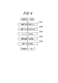
- FIG. 4 is a flowchart showing an operation procedure in the steady operation mode in the first embodiment.
- the control unit 103 reads the device determination result obtained through the device determination mode from the storage unit 12 in the control unit 103 (step S301). Based on the read device determination result, the control unit 103 sets the boost ratio shown in Table 2 for the voltage converters 3a to 3e (step S302). For example, since the determination results of the power supply devices 1a to 1c read in step S302 are all “solar cells”, the control unit 103 converts the voltage conversion corresponding to the power supply devices 1a to 1c based on the correspondence table of Table 2. 1.25 is set as the step-up ratio of the devices 3a to 3c.
- the control unit 103 determines the boost ratio of the voltage converter 3d corresponding to the power supply device 1d based on the correspondence table of Table 2. Set 1.88. Further, since the determination result of the power supply device 1e read in step S301 is “storage battery”, the control unit 103 sets the boost ratio of the voltage converter 3e corresponding to the power supply device 1e as 1. based on the correspondence table of Table 2. 58 is set. By setting these step-up ratios, the output voltage of each power supply device from the voltage converters 3a to 3e is theoretically DC 300V, which is a DC link voltage.
- the control unit 103 sets the inverter 6 so that the inverter 6 converts DC 300V input power into single-phase AC 200V power (step S303).
- the inverter 6, the switches 7a and 7b, and the load connection terminals 8a and 8b are not included in the power supply device determination device of the present invention, but are described as included in the power conversion device.
- the power device determination apparatus may be configured to include these.
- control unit 103 starts output from the power supply devices 1a to 1e (step S304) and confirms that the output power from the voltage converters 3a to 3e is about DC 300V.
- Output power from the voltage converters 3 a to 3 e is DC-linked and input to the inverter 6.
- the control unit 103 also monitors the voltage after passing through the inverter 6, confirms that a predetermined AC voltage of 200V is obtained, and then turns on the switch 7a to start supplying power to the load 9 (Step S103). S305).
- control unit 103 may be configured by hardware, or a function may be realized by causing a CPU to execute a program.
- the output voltages of the voltage converters 3a to 3e are measured by the individual voltage measuring devices 4a to 4e.
- the present invention is not limited to this, and for example, a single voltage measurement is performed. Only the vessel 4 may be provided. That is, at the timing of steps S103, S106, S109, S112, and S115 in FIG. 2, the control unit 103 switches the input to the voltage measuring device 4 with a multiplexer, and the voltage measuring device 4 changes the output voltages of the voltage converters 3a to 3e. You may comprise so that it can measure sequentially.
- inverter 6 in this embodiment described having controlled the output voltage by the control part 103, this invention is not limited to this, You may set up so that it may become a predetermined output voltage.
- a single-phase three-wire AC 200V is output from the load connection terminal 8a as an AC power output.
- an inverter 6 ′ for converting to three-phase 200 V may be arranged in place of the inverter 6 in order to cope with a commercial refrigerator, air conditioner, motor drive in a factory, and the like.
- the description has been made on the assumption that an electric device that can be used in Japan as a load to be connected.
- the load can be appropriately changed in consideration of the use of an electric device that can be used outside of Japan.
- the control unit 103 may control the inverter 6 so as to output AC 220 to 240V, or an inverter 6 ′′ that can output AC 220 to 240V may be arranged instead of the inverter 6.
- Electrical devices that can be used in Asia, Oceania and Europe can also be configured to be connectable.
- the type of the connected power supply device is automatically determined in the device determination mode, and the output power of each power supply device is boosted in the steady operation mode based on the determination result. It was configured to set the ratio automatically. As a result, the user can individually check the type of the connected power supply device or manually set the DC / DC converter so as to boost the output voltage at the boost ratio corresponding to the type of the device. It becomes unnecessary.
- the voltage monitoring of the power supply device is always performed even during steady operation, and the type of the power supply device can be determined using the voltage measuring devices 4a to 4e used for the voltage monitoring. Therefore, the power supply device can be determined without adding any special circuit.
- FIG. 5 is a block diagram showing a configuration of the power conversion device 113 including the power supply device determination device 110 according to the second embodiment of the present invention.
- the power supply device determination apparatus 110 includes a power supply device connection unit 101 for connecting a plurality of power supply devices, a voltage measurement unit 111 for measuring an output voltage from each power supply device, and each component. And a control unit 112 for controlling.
- the power converter device 113 is further provided with the load connection part 104 for connecting with a load.
- the configurations of the power supply device connection unit 101 and the load connection unit 104 are the same as those of the first embodiment of the present invention, and thus detailed description thereof is omitted.
- voltage measurement is different from the configuration of the first embodiment.
- the unit 111 and the control unit 112 will be described.
- the voltage measuring unit 111 includes voltage measuring devices 4a to 4e for measuring the voltage of the DC power output from the voltage converters 3a to 3e.
- the connection switches 5a to 5e are further provided in the subsequent stage of the voltage converters 3a to 3e and in the previous stage of the inverter 6.
- the connection switches 5a to 5e are controlled by the control unit 112 and are turned off in the device determination mode so that the voltage of the power supply device output after boosting can be individually monitored.
- the connection switches 5 a to 5 e are turned on, and the outputs of the respective power supply devices are DC-linked at the previous stage of the inverter 6 and controlled to be input to the inverter 6.
- the control unit 112 controls the power supply devices 1a to 1e, the voltage converters 3a to 3e, the voltage measuring devices 4a to 4e, the connection switches 5a to 5e, the inverter 6, the switches 7a and 7b, and the load 9 according to the control signal 11 shown in FIG. These components can be controlled in various ways. Specifically, the control unit 112 controls the ON / OFF of the power supply devices 1a to 1e, sets the step-up ratio of the voltage converters 3a to 3e, controls the voltage measuring devices 4a to 4e and reads the measured values, and connects the switch 5a. Control of 5 to 5e, setting of the inverter 6, control of the switches 7a and 7b, ON / OFF control of the load 9, etc. are possible.
- the device determination mode for determining the type of the power supply device and the subsequent steady operation mode in the second embodiment will be individually described below.
- the voltage converters 3a to 3e in the power device connection unit 101 boost the output power of the power devices 1a to 1e with the same boost ratio.
- the output power of the power supply devices 1a to 1e is boosted at the same boost ratio 1.2, and the output power is input to the voltage measuring devices 4a to 4e.
- an arbitrary value of 1 or more and 2 or less can be set as the step-up ratio in this device determination mode.
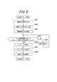
- FIG. 6 is a flowchart showing the procedure for determining the power supply device in the second embodiment.
- the control unit 112 of the power supply device determination device 110 first turns off the connection switches 5a to 5e and cancels the DC link of the output power from the voltage converters 3a to 3e (step S401).
- the control unit 112 turns on the outputs of the power supply devices 1a to 1e all at once (step S402), and boosts the output power of the power supply devices 1a to 1e by the voltage converters 3a to 3e (step S403).
- control unit 112 After boosting at step S403, the control unit 112 measures the boosted output voltage of the power supply devices 1a to 1e by the voltage measuring devices 4a to 4e (step S404), and the measurement result is stored in the control unit 112. Store in the storage unit 12 (step S405). The control unit 112 determines the power supply devices 1a to 1e based on the stored output voltage measurement result (steps S406 to S410), and ends the device determination mode.
- FIG. 7 shows in detail a flowchart of the determination procedure of the power supply devices 1a to 1e in steps S406 to S410.
- the control unit 112 reads the corresponding output voltage measurement result stored in the storage unit 12 (step S501). Next, it is determined whether or not the read output voltage measurement result is within the range of the predetermined range A shown in Table 1 (step S502). It is determined that there is (step S503).
- the control unit 112 stores the determination result of the power supply device 1a in the storage unit 12 in the control unit 112 (step S509), and the determination ends.
- the control unit 112 next determines whether or not the read output voltage measurement result is within the predetermined range B shown in Table 1 (step S504).
- the control unit 112 determines that it is within the range of the predetermined range B, it is determined that the power supply device is a “storage battery” (step S505), and the determination result of the power supply device is stored in the storage unit 12 in the control unit 112 ( In step S509), the determination ends. If it is determined that it is not within the range of the predetermined range B, then the control unit 112 determines whether or not the read output voltage measurement result is within the range of the predetermined range C shown in Table 1 (step S506).
- the control unit 112 determines that the power supply device is within the predetermined range C
- the power supply device is determined to be a “fuel cell” (step S507), and the determination result of the power supply device is stored in the storage unit 12 in the control unit 112.
- the determination ends When the read output voltage measurement result does not correspond to any of the predetermined ranges A to C, it is determined that there is no connection (step S508), and the determination result of the power supply device is stored in the storage unit 12 in the control unit 112. (Step S509), the determination ends.
- the control unit 112 ends the device determination mode after determining all the power supply devices.
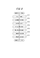
- FIG. 8 is a flowchart showing an operation procedure in the steady operation mode in the second embodiment.
- the control unit 112 reads the device determination result obtained through the device determination mode from the storage unit in the control unit 112 (step S601). Based on the read device determination result, the control unit 112 sets the step-up ratio described in Table 2 for the voltage converters 3a to 3e (step S602). For example, since the determination results of the power supply devices 1a to 1c read out in step S601 are all “solar cells”, the control unit 112 performs voltage conversion corresponding to the power supply devices 1a to 1c based on the correspondence table of Table 2. 1.25 is set as the step-up ratio of the devices 3a to 3c.
- the control unit 112 determines the boost ratio of the voltage converter 3d corresponding to the power supply device 1d based on the correspondence table of Table 2. Set 1.88. Further, since the determination result of the power supply device 1e read out in step S601 is “storage battery”, the control unit 112 sets the boost ratio of the voltage converter 3e corresponding to the power supply device 1e as 1. based on the correspondence table of Table 2. 58 is set. By setting these step-up ratios, the output voltage of each power supply device from the voltage converters 3a to 3e is theoretically about 300V.
- the control unit 112 starts outputting power from the power supply device (step S603).
- the power from the power supply device 1a will be described as an example.
- the control unit calculates a ratio between the DC link voltage Vd (300 V in this embodiment) and the boosted output voltage Vac of the power supply device 1a to obtain a predetermined threshold value. It is confirmed that the expression (1) is satisfied for ⁇ (step S604). If the expression (1) is not satisfied, the step-up ratio preset in step S602 is corrected (step S605). Specifically, the boost ratio is changed so that the boost ratio Rad represented by Expression (2) is obtained when the corrected boost ratio is Rad and the uncorrected boost ratio is Rac.
- the above procedure is continued until the boosted output voltages Vac to Vec of all power supply devices satisfy the expression (1).
- the subscript a in the expressions (1) and (2) indicates that the relational expression is related to the power supply device 1a, and the subscripts b to e are replaced with the subscripts b to e, respectively. Shall.
- control unit 112 sets the inverter 6 so as to convert DC 300V input power to the inverter 6 into single-phase AC 200V power (step S606).
- the inverter 6, the switches 7a and 7b, and the load connection terminals 8a and 8b are not included in the power supply device determination device of the present invention, but are included in the power conversion device of the present invention.
- the power supply device determination apparatus may be configured to include these.
- control unit 112 turns on the connection switches 5a to 5e and monitors the voltage after passing through the inverter 6. Then, after confirming that the predetermined AC 200V is obtained, the control unit 112 turns on the switch 7a and starts supplying power to the load 9 (step S608).
- connection switches 5a to 5e are provided at the subsequent stage of the voltage converters 3a to 3e, and the connection switches are turned off in the device determination mode. .
- the boosting ratio is corrected from the ratio of the boosted output voltage of the power supply device and the DC link voltage.
- the third embodiment of the present invention has the same hardware configuration as that of the second embodiment, although the operation of the control unit 112 is different from that of the first and second embodiments. Therefore, in the following description, the block diagram of FIG. 5 is referred for the configuration of the present embodiment.
- the device determination mode for determining the type of power supply device and the subsequent steady operation mode in the third embodiment will be individually described below.
- the voltage converters 3a to 3e in the power device connection unit 101 boost the output power of the power devices 1a to 1e with the same boost ratio.
- the output power of the power supply devices 1a to 1e is boosted at the same boost ratio 1.2, and the output power is input to the voltage measuring devices 4a to 4e.
- an arbitrary value of 1 or more and 2 or less can be set as the step-up ratio in this device determination mode.
- FIG. 9 is a flowchart showing the procedure for determining the power supply device in the third embodiment.
- the control unit 112 of the power supply device determination device 110 first turns off the connection switches 5a to 5e and cancels the DC link of the output power from the voltage converters 3a to 3e (step S701).
- the control unit 112 turns on the outputs of the power supply devices 1a to 1e all at once (step S702), and boosts the output power of the power supply devices 1a to 1e by the voltage converters 3a to 3e (step S703).
- the control unit 112 measures the boosted output voltage of the power supply devices 1a to 1e using the voltage measuring devices 4a to 4e (step S704).
- the control unit 112 stores the output voltage measurement result in the storage unit 12 in the control unit 112 (step S705).
- the control unit 112 calculates the optimum boost ratio for each power supply device 1a to 1e based on the stored output voltage measurement result. More specifically, for example, in step S703 of the power supply device 1a, when the output voltage after boosting with the boost ratio Rf is Vaf, the control unit 112 uses the DC link voltage Vd as the optimum boost ratio Rad of the power supply device 1a. It is calculated by the following equation (3). Note that the subscript a in the expression (3) indicates that the relational expression is related to the power supply device 1a, and the subscripts b to e are replaced with the subscripts b to e to indicate the relational expressions regarding the power supply devices 1b to 1e, respectively.
- the control unit 112 calculates the optimum boost ratios Rad to Red for all the power supply devices 1a to 1e (step S706), and stores the calculation results in the storage unit 12 in the control unit 112 (step S707). Thereafter, the device determination mode ends.
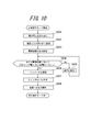
- FIG. 10 is a flowchart showing an operation procedure in the steady operation mode in the third embodiment.
- the control unit 112 reads the calculation result of the optimum boost ratio for each device obtained through the device determination mode from the storage unit 12 in the control unit 112 (step S801). Based on the read calculation result, the control unit 112 sets an optimum step-up ratio for the voltage converters 3a to 3e (step S802). By setting these optimum boost ratios, the output voltages of the power supply devices from the voltage converters 3a to 3e theoretically become DC link voltages.
- the control unit 112 starts outputting power from the power supply device (step S803).
- the control unit calculates a ratio between the DC link voltage Vd (300 V in the present embodiment) and the output voltage Vac after boosting the power supply device, and sets the predetermined threshold value ⁇ .
- the expression (1) is satisfied (step S804).
- the boost ratio is corrected (step S805). Specifically, the boost ratio is changed so that the boost ratio expressed by the equation (2) is obtained when the corrected boost ratio is Rad and the uncorrected boost ratio is Rac. The above operation is continued until the boosted output voltages Vac to Vec satisfy the expression (1) for all the power supply devices 1a to 1e.
- control unit 112 sets the inverter 6 so as to convert DC 300V input power to the inverter 6 into single-phase AC 200V power (step S806).
- the inverter 6, the switches 7a and 7b, and the load connection terminals 8a and 8b are not included in the power supply device determination device of the present invention, but are included in the power conversion device of the present invention.
- the power supply device determination apparatus may be configured to include these.
- control unit 112 turns on the connection switches 5a to 5e (step S807) and monitors the voltage after passing through the inverter 6. Then, after confirming that a predetermined AC voltage of 200 V is obtained, the control unit 112 turns on the switch 7a and starts supplying power to the load 9 (step S808).
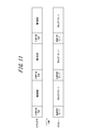
- the device determination mode and the steady operation mode shown in FIGS. 9 and 10 can be repeatedly executed. Specifically, as shown in FIG. 11, even after shifting from the device determination mode to the steady operation mode, the device determination mode is periodically executed, and the boost ratio is always determined based on the latest output voltage of the power supply device. It can be constituted as follows. Note that when the device determination mode is executed, the switch 7a is turned off and the switch 7b is turned on to supply power to the load from the commercial power supply system 10 as shown in FIG. .
- the optimum boost ratio is calculated from the ratio of the output voltage and the DC link voltage with the fixed boost ratio, an unknown power supply device is connected.
- the switch 7b may be appropriately turned on according to the excess or deficiency of power supply from the power supply device, and connected to the commercial power supply system.
- Computer systems and other hardware include, for example, general-purpose computers, PCs (personal computers), dedicated computers, workstations, PCS (Personal Communications System, personal mobile communication systems), RFID receivers, electronic notepads, laptop computers, A GPS (Global Positioning System) receiver or other programmable data processing device is included.
- the various operations are performed by dedicated circuitry implemented with program instructions (software) (eg, individual logic gates interconnected to perform a specific function) or one or more processors. Note that it is executed by a logic block, a program module, or the like.
- microprocessors include, for example, one or more microprocessors, CPU (Central Processing Unit), ASIC (Application Specific Integrated Circuit), DSP (Digital Signal Processor), PLD (Programmable Logic (Device), FPGA (Field Programmable Gate Array), processor, controller, microcontroller, microprocessor, electronics, other devices designed to perform the functions described here, and / or any combination of these It is.
- the embodiments shown here are implemented, for example, by hardware, software, firmware, middleware, microcode, or any combination thereof.
- the instructions may be program code or code segments for performing the necessary tasks.
- the instructions can then be stored on a machine-readable non-transitory storage medium or other medium.
- a code segment may represent any combination of procedures, functions, subprograms, programs, routines, subroutines, modules, software packages, classes or instructions, data structures or program statements.
- a code segment transmits and / or receives information, data arguments, variables or stored contents with other code segments or hardware circuits, thereby connecting the code segments with other code segments or hardware circuits .
- the network used here is the Internet, ad hoc network, LAN (Local Area Network), cellular network, WPAN (Wireless Personal Area Network) or other network, or any combination of these. Is included.
- Examples of the components of the wireless network include an access point (for example, a Wi-Fi access point), a femto cell, and the like.
- wireless communication devices include Wi-Fi, Bluetooth (registered trademark), cellular communication technology (for example, CDMA (Code Division Multiple Access), TDMA (Time Division Multiple Access), FDMA (Frequency Division Multiple Access), OFDMA (Orthogonal Frequency Frequency). Division (Multiple Access), SC-FDMA (Single-Carrier Frequency Division Multiple Access), or other wireless technologies and / or wireless standards using technology standards.
- the machine-readable non-transitory storage medium used herein can be further configured as a computer readable tangible carrier (medium) comprised of solid state memory, magnetic disk and optical disk categories, and so on.
- the medium stores an appropriate set of computer instructions such as a program module for causing a processor to execute the technology disclosed herein, and a data structure.
- Computer readable media include electrical connections with one or more wires, magnetic disk storage media, magnetic cassettes, magnetic tape, and other magnetic and optical storage devices (eg CD (Compact Disk), laser disks ( Registered trademark), DVD (registered trademark) (Digital Versatile Disc), floppy (registered trademark) disk and Blu-ray Disc (registered trademark)), portable computer disk, RAM (Random Access Memory), ROM (Read-Only Memory), It includes a rewritable and programmable ROM such as EPROM, EEPROM or flash memory or other tangible storage medium capable of storing information or any combination thereof.
- the memory can be provided inside and / or outside the processor / processing unit.
- the term “memory” means any type of long-term storage, short-term storage, volatile, non-volatile, or other memory in which a particular type or number of memories or storage is stored. The type of medium is not limited.
Landscapes
- Engineering & Computer Science (AREA)
- Power Engineering (AREA)
- Physics & Mathematics (AREA)
- General Physics & Mathematics (AREA)
- Dc-Dc Converters (AREA)
- Inverter Devices (AREA)
- Direct Current Feeding And Distribution (AREA)
- Control Of Electrical Variables (AREA)
Abstract
DCリンクを採用した電力変換装置において、接続されている電源機器の種類を自動で判定するための判定装置及び判定方法を提供する。 複数の電源機器を接続可能な複数の接続部と、複数の接続部に直列接続される複数の電圧変換部と、複数の電圧変換部通過後の各出力電圧値を測定する電圧測定部と、複数の電圧変換部の昇圧比を同一とした時の電圧測定部による電圧測定結果に基づき複数の電源機器を判定する手段を有する制御部とを備える判定装置により、接続された電源機器を自動判定する。
Description
関連出願の相互参照
本出願は、2013年7月29日に出願された日本国特許出願第2013-157085号に基づく優先権を主張するものであり、この特許出願の明細書全体を参照によって本願明細書に引用する。
本出願は、2013年7月29日に出願された日本国特許出願第2013-157085号に基づく優先権を主張するものであり、この特許出願の明細書全体を参照によって本願明細書に引用する。
本発明は、電源機器の種類を判定するための電源機器判定装置、電源機器判定方法及びそれらを備えた電力変換装置に関するものである。
電力制御システムにおいて、太陽電池、蓄電池、燃料電池、風力発電機及び水力発電機などの複数の電源機器を一元的に管理・運用することが求められている。特に近年、制御の容易化、効率の向上、コストダウン等の観点から各電源機器を直流電力のままで繋ぐDCリンクシステムが提案されている。これは、太陽電池、燃料電池等からの電力を直流電力のままリンクさせ、直接蓄電池に充電し、1つのインバータを使って交流電力に変換し負荷に供給するシステムである。このDCリンクシステムは、従来のように電源機器ごとに出力をインバータで変換する必要がないため変換ロスが少なく効率の向上が見込める。またDCリンクシステムによれば、システムが簡素になりコストダウンが実現できる。更に、DCリンクシステムは、直流電力をリンクさせるので電力の制御も容易になる等の利点がある。
このDCリンクシステムに接続する複数の電源機器は通常、機器ごとに出力電圧が異なる。従って直流電力のままでこれらの機器の出力を接続してDCリンクシステムを構成するためには、複数の電源機器からの出力を同一の電圧まで昇圧しなければならない。ところが、従来の電力制御システムにおいては、どのような電源機器がシステムに接続されているのかを自動判定することが困難であった。従って特許文献1のような電力制御システムにおいて、利用者はシステムに接続される複数の電源機器からの出力電力を負荷に合った電力に変換するために機器ごとに個別に設定を行う必要があった。
そして、このDCリンクシステムにおいても、利用者は接続されている電源機器の種類を個別に確認し、その機器の種類に対応する昇圧比で出力電圧を昇圧するようにDC/DC変換器の設定を行う必要があった。
上述した点に鑑みてなされた本発明の目的は、DCリンクを採用した電力変換装置において、接続されている電源機器を自動で判定するための判定装置を提供することである。
上述した諸課題を解決すべく、本発明に係る電源機器の判定装置は、
複数の電源機器を接続可能な電源機器の判定装置であって、
前記複数の電源機器を接続可能な複数の接続部と、
前記複数の接続部に直列接続される複数の電圧変換部と、
前記複数の電圧変換部通過後の各出力電圧値を測定する電圧測定部と、
前記複数の電圧変換部の昇圧比を同一とした時の前記電圧測定部による電圧測定結果に基づき、前記複数の電源機器を判定する手段を有する制御部と
を備えることを特徴とする。
複数の電源機器を接続可能な電源機器の判定装置であって、
前記複数の電源機器を接続可能な複数の接続部と、
前記複数の接続部に直列接続される複数の電圧変換部と、
前記複数の電圧変換部通過後の各出力電圧値を測定する電圧測定部と、
前記複数の電圧変換部の昇圧比を同一とした時の前記電圧測定部による電圧測定結果に基づき、前記複数の電源機器を判定する手段を有する制御部と
を備えることを特徴とする。
また、前記制御部は、前記複数の電圧変換部の昇圧比を同一とした時の前記電圧測定部による前記電圧測定結果に基づき、前記複数の電源機器を判定する機器判定モードと、前記複数の電圧変換部の昇圧比を個別制御する定常動作モードとを切り替えることが好ましい。
また、前記制御部は、前記機器判定モードによる前記複数の電源機器の判定結果に基づいて、前記複数の電圧変換部の昇圧比の個別制御を行うことが好ましい。
また、前記制御部は、前記定常動作モードにおける前記複数の電圧変換部の出力電圧が同一になるように前記複数の電圧変換部の昇圧比の個別制御を行うことが好ましい。
また、前記複数の電圧変換部からの出力電力の連結をON/OFFする為の連結スイッチを更に有し、
前記制御部は、前記機器判定モードにおいて前記連結スイッチをOFF状態とし、前記定常動作モードにおいて前記連結スイッチをON状態とすることが好ましい。
前記制御部は、前記機器判定モードにおいて前記連結スイッチをOFF状態とし、前記定常動作モードにおいて前記連結スイッチをON状態とすることが好ましい。
また、前記複数の電源機器の判定は、前記複数の電源機器の種類の特定であることが好ましい。
また、前記複数の電源機器の判定は、前記複数の電源機器の最適昇圧比の決定であることが好ましい。
さらに、上述した諸課題を解決すべく、本発明に係る電力変換装置は、
複数の電源機器を接続可能な電力変換装置であって、
前記複数の電源機器を接続可能な複数の接続部と、
前記複数の接続部に直列接続される複数の電圧変換部と、
前記複数の電圧変換部通過後の各出力電圧値を測定する電圧測定部と、
前記複数の電圧変換部の昇圧比を同一とした時の前記電圧測定部による電圧測定結果に基づき、前記複数の電源機器を判定する機器判定モードと、前記複数の電圧変換部の昇圧比を個別制御する定常動作モードとを切り替え可能に制御する制御部と
を備えることを特徴とする。
複数の電源機器を接続可能な電力変換装置であって、
前記複数の電源機器を接続可能な複数の接続部と、
前記複数の接続部に直列接続される複数の電圧変換部と、
前記複数の電圧変換部通過後の各出力電圧値を測定する電圧測定部と、
前記複数の電圧変換部の昇圧比を同一とした時の前記電圧測定部による電圧測定結果に基づき、前記複数の電源機器を判定する機器判定モードと、前記複数の電圧変換部の昇圧比を個別制御する定常動作モードとを切り替え可能に制御する制御部と
を備えることを特徴とする。
さらに、上述した諸課題を解決すべく、本発明に係る電源機器の判定方法は、
複数の電源機器を接続可能な電源機器の判定方法であって、
前記複数の電源機器の出力電力を同一の昇圧比で電圧変換を行う第1の電圧変換ステップと、
前記第1の電圧変換ステップにより電圧変換された電圧変換部通過後の各出力電圧値を測定する電圧測定ステップと、
前記電圧測定ステップにより測定された各出力電圧値に基づいて、前記複数の電源機器を判定する判定ステップと
を有することを特徴とする。
複数の電源機器を接続可能な電源機器の判定方法であって、
前記複数の電源機器の出力電力を同一の昇圧比で電圧変換を行う第1の電圧変換ステップと、
前記第1の電圧変換ステップにより電圧変換された電圧変換部通過後の各出力電圧値を測定する電圧測定ステップと、
前記電圧測定ステップにより測定された各出力電圧値に基づいて、前記複数の電源機器を判定する判定ステップと
を有することを特徴とする。
また、前記判定ステップによる電源機器の判定情報に基づき、前記複数の電圧変換部の昇圧比を個別制御する第2の電圧変換ステップを更に有することが好ましい。
本発明によれば、DCリンクを採用した電力変換装置において、接続される複数の電源機器を自動で判定しDC/DC変換後の出力電圧が同一になるように制御することが可能となる。
以下、本発明の実施形態について、図面を参照しながら詳細に説明する。
(第1の実施形態)
図1は、本発明の第1の実施形態に係る電源機器判定装置100を含む電力変換装置105の構成を示すブロック図である。本実施の形態に係る電源機器判定装置100は、複数の電源機器を接続するための電源機器接続部101と、各電源機器からの出力電圧を測定するための電圧測定部102と、各構成要素を制御するための制御部103とを有する。また、電力変換装置105は、負荷と接続するための負荷接続部104を更に備える。
図1は、本発明の第1の実施形態に係る電源機器判定装置100を含む電力変換装置105の構成を示すブロック図である。本実施の形態に係る電源機器判定装置100は、複数の電源機器を接続するための電源機器接続部101と、各電源機器からの出力電圧を測定するための電圧測定部102と、各構成要素を制御するための制御部103とを有する。また、電力変換装置105は、負荷と接続するための負荷接続部104を更に備える。
まず、電源機器接続部101の構成及び動作について説明する。電源機器接続部101は、各電源機器1a~1eを接続するための電源機器接続端子2a~2eを備える。また電源機器接続部101は、各電源機器から入力された電力に対してDC/DC変換を行うための電圧変換器3a~3eを更に備える。電圧変換器により昇圧又は降圧された電力は、電圧測定部102内の電圧測定器4a~4eに出力される。
電源機器接続端子2a~2eは、各電源機器と本発明の電力変換装置との間で電力の入出力を行うための電力端子の他、制御部103が各電源機器の制御を行うための制御信号端子を備えることができる。本実施形態においては、電源機器接続端子2a~2cには、それぞれ電源機器1a~1c(太陽電池)が接続される。また、電源機器接続端子2dには電源機器1d(燃料電池)が接続される。電源機器接続端子2eには電源機器1e(蓄電池)が接続される。
太陽電池は太陽光のエネルギーを直流電力に変換するものである。太陽電池は、例えば光電変換セルを多数直列に接続し、太陽光が照射されたときに所定の電流を出力するように構成される。本実施形態において電源機器接続端子2a~2cに接続する太陽電池には、例えばシリコン系多結晶太陽電池を使用することができる。また、太陽電池はこれに限定されるものではなく、シリコン系単結晶太陽電池、あるいはCIGS等の薄膜太陽電池等、光電変換可能なものであればよく、太陽電池の種類が制限されるものではない。
燃料電池は、水素を燃料に用いて空気中の酸素との化学反応により直流電力を発電するものである。燃料電池は、電解質に用いる物質によって固体酸化物形燃料電池(Solid Oxide Fuel Cell)や固体高分子形燃料電池(Polymer Electrolyte Fuel Cell)等に分類される。本実施形態の燃料電池は、特にその燃料電池の種類が制限されるものではない。
本実施形態に用いられる蓄電池は、例えばリチウムイオン電池を用いることができる。また、ニッケル水素電池等の他の種類の蓄電池も使用することができる。また、蓄電池単体の他、電気自動車(EV)やプラグインハイブリッド車(PHV)に搭載されている蓄電池に対して充電を行うことも可能である。
なお、電源機器接続端子2a~2eに接続する電源機器は、太陽電池、燃料電池及び蓄電池を含むほか、風力発電機、小型水力発電機など、交流電力を整流して出力するものを含んでもよい。
電圧変換器3a~3eは、各電源機器の出力電圧に対して制御部103からの制御信号11に基づいて所定の昇圧比でDC/DC変換を行う。なお、本明細書において、昇圧比とは、各電圧変換器3a~3eにおける直流入力電圧値に対する直流出力電圧値の比を指すものとする。
次に電圧測定部102の構成及び動作について説明する。電圧測定部102は、電圧変換器3a~3eから出力された直流電力の電圧を測定するための電圧測定器4a~4eを備える。本実施形態においては、各電圧変換器3a~3eの出力電圧を個別の電圧測定器4a~4eで測定するように構成される。
次に制御部103の構成及び動作について説明する。制御部103は、図1に示す制御信号11により、電源機器1a~1e、電圧変換器3a~3e、電圧測定器4a~4e、後述する負荷接続部104内のインバータ6、スイッチ7a,7b、負荷9と通信可能に構成され、これらの構成要素の各種制御が可能である。具体的には、制御部103は、電源機器1a~1eのON/OFF制御、電圧変換器3a~3eの昇圧比の設定、電圧測定器4a~4eの制御及び測定値の読み出し、インバータ6の設定、スイッチ7a,7bの制御、負荷9のON/OFF制御等が可能である。
なお、本実施形態において、制御部103が各構成要素を制御するための制御信号11の経路を図1中に実線により示したが、この制御信号の伝送は有線による通信を用いても良いし、無線通信を用いることもできる。
次に負荷接続部104の構成及び動作について説明する。この負荷接続部104は、本発明の電源機器判定装置100には含まれないが、本発明の電力変換装置105に含まれる。負荷接続部104は、電圧測定部102から供給される直流電力を変換するインバータ6、並びにインバータ6の出力を負荷9に接続する負荷接続端子8aを備える。
インバータ6は、電圧測定部102からの電力を負荷9に対応した単相3線の交流200Vに変換する。交流200Vに変換された電力は、負荷接続端子8aに接続された負荷9に供給する。インバータ6は、制御部103からの制御信号11を基に、上述のように接続された負荷に対応した最適な電力への変換を行う。
負荷接続端子8aは、負荷9との間で電力の入出力を行うための電力端子の他、制御部103が負荷9の制御を行い得るように制御信号端子を備えることができる。本実施形態においては、負荷接続端子8aには、単相3線の交流200Vで動作する負荷9が接続される。ここで負荷9は、交流200Vの単相3線のうちの中性相を含む2線を引き出して供給する交流100V駆動の負荷である。負荷9の例としては、冷蔵庫、非常用電灯、給湯システム又は家庭用ネットワークサーバーなどの停電を極力回避すべき電気製品の他、ドライヤー、家庭用ゲーム機又は音楽鑑賞用オーディオシステムなどの家庭用一般負荷などが挙げられる。
負荷9への電力の供給は、図1に示すように、スイッチ7a及び7bを切り替えることにより、負荷接続端子8bに接続した商用電源系統10からの供給と、インバータ6からの供給とを切り替え可能に構成する。なお、この切り替えは制御部103が監視する商用電源系統10及びインバータ6の出力電圧等に基づいて行われる。
次に、第1の実施形態における、電源機器の種類を判定するための機器判定モードと、その後の定常動作モードについて、以下に個別に説明する。
(機器判定モードの動作)
機器判定モードにおいて、電源機器接続部101内の電圧変換器3a~3eは、同一の昇圧比で電源機器1a~1eの出力電力を昇圧する。本実施形態においては、電源機器1a~1eの出力電力を順次同一の昇圧比1.2で昇圧し、その出力電力を電圧測定器4a~4eに入力する。なお、この機器判定モードにおける昇圧比は、1以上2以下の任意の値を設定することができる。
機器判定モードにおいて、電源機器接続部101内の電圧変換器3a~3eは、同一の昇圧比で電源機器1a~1eの出力電力を昇圧する。本実施形態においては、電源機器1a~1eの出力電力を順次同一の昇圧比1.2で昇圧し、その出力電力を電圧測定器4a~4eに入力する。なお、この機器判定モードにおける昇圧比は、1以上2以下の任意の値を設定することができる。
図2は、第1の実施形態における、電源機器判定の手順をフローチャートにより示す。まず、電源機器判定装置100の制御部103は、機器判定モード開始の後、電源機器1a~1eをON状態にする(ステップS101)。次に制御部103は電源機器1aの出力電力のみを電圧変換器3aにより昇圧する(ステップS102)。この時、電圧変換器3b~3eは動作させておらず、電圧変換器3b~3eのインバータ6入力側は開放されている。従って電圧変換器3b~3eの出力は電圧変換器3aの出力電圧及び電圧測定器4aの測定結果には何ら影響を与えない。制御部103は、ステップS102で昇圧を行った後、電圧測定器4aにより電源機器1aの昇圧後の出力電圧の測定を行う(ステップS103)。制御部103は、出力電圧の測定結果に基づいて電源機器1aの判定を行う(ステップS104)。
図3は、ステップS104における、電源機器1a~1eの判定の手順をフローチャートにより詳細に示す。制御部103は、判定開始後、電圧測定器4aによる電圧変換器3aの出力電圧測定結果が表1に示す所定範囲Aの範囲内であるかどうか判定する(ステップS201)。制御部103が所定範囲Aの範囲内であると判断すると、電源機器1aは「太陽電池」であると判定される(ステップS202)。制御部103は、電源機器1aの判定結果を制御部103内の記憶部12に記憶し(ステップS208)、判定は終了する。

次に制御部103は電源機器1bの出力電力のみを電圧変換器3bにより昇圧する(ステップS105)。ステップS102と同様に、電圧変換器3a及び3c~3eは動作させておらず、電圧変換器3a及び3c~3eのインバータ6入力側は開放されている。従って、電圧変換器3a及び3c~3eの出力は電圧変換器3bの出力電圧及び電圧測定器4bの測定結果には何ら影響を与えない。これは、以下に説明する電源機器1c~1eの判定においても同様である。制御部103は、ステップS105で昇圧を行った後、電圧測定器4bにより電源機器1bの昇圧後の出力電圧の測定を行い(ステップS106)、その結果に基づいて電源機器1bの判定を行う(ステップS107)。
制御部103は、電圧測定器4bによる電圧変換器3bの出力電圧測定結果が表1に示す所定範囲Aの範囲内であるかどうか判定する(ステップS201)。制御部103が所定範囲Aの範囲内であると判断すると、電源機器1bは「太陽電池」であると判定され(ステップS202)、電源機器1bの判定結果を制御部103内の記憶部12に記憶し(ステップS208)、判定は終了する。なお、上記と同様の手順により電源機器1cについても「太陽電池」であると判定される。
次に制御部103は電源機器1dの出力電力のみを電圧変換器3dにより昇圧する(ステップS111)。ステップS102と同様に、電圧変換器3a~3c及び3eは動作させておらず、電圧変換器3a~3c及び3eのインバータ6入力側は開放されている。従って、電圧変換器3a~3c及び3eの出力は電圧変換器3dの出力電圧及び電圧測定器4dの測定結果には何ら影響を与えない。制御部103は、ステップS111で昇圧を行った後、電圧測定器4dにより電源機器1dの昇圧後の出力電圧の測定を行い(ステップS112)、その結果に基づいて電源機器1dの判定を行う(ステップS113)。
制御部103は、電圧測定器4dによる電圧変換器3dの出力電圧測定結果が表1に示す所定範囲Aの範囲内であるかどうか判定し(ステップS201)、所定範囲Aの範囲内ではないと判断すると、次に所定範囲Bの範囲内であるかどうか判定する(ステップS203)。制御部103が所定範囲Bの範囲内ではないと判断すると、次に所定範囲Cの範囲内であるかどうか判定する(ステップS205)。制御部103が所定範囲Cの範囲内であると判断すると、電源機器1dは「燃料電池」であると判定され(ステップS206)、電源機器1dの判定結果を制御部103内の記憶部12に記憶し(ステップS208)、判定は終了する。なお、ステップS205で所定範囲Cの範囲内に無いと判断すると、想定している電源機器の接続は無いと判定し(ステップS207)、判定結果を制御部103内の記憶部12に記憶し(ステップS208)、判定を終了する。
次に制御部103は電源機器1eの出力電力のみを電圧変換器3eにより昇圧する(ステップS114)。ステップS102と同様に、電圧変換器3a~3dは動作させておらず、電圧変換器3a~3dのインバータ6入力側は開放されており、電圧変換器3a~3dの出力は電圧変換器3eの出力電圧及び電圧測定器4eの測定結果には何ら影響を与えないように構成される。制御部103は、ステップS114で昇圧を行った後、電圧測定器4eにより電源機器1eの昇圧後の出力電圧の測定を行い(ステップS115)、その結果に基づいて電源機器1eの判定を行う(ステップS116)。
制御部103は、電圧測定器4eによる電圧変換器3eの出力電圧測定結果が表1に示す所定範囲Aの範囲内であるかどうか判定する(ステップS201)。制御部103は、所定範囲Aの範囲内ではないと判断すると、次に所定範囲Bの範囲内であるかどうか判断する(ステップS203)。ここで制御部103は、所定範囲Bの範囲内であると判断すると、電源機器1eは「蓄電池」であると判定され(ステップS204)、電源機器1eの判定結果を制御部103内の記憶部12に記憶し(ステップS208)、判定は終了する。
制御部103は、全ての電源機器の判定を終えると、機器判定モードを終了する。なお、表1において、太陽電池の出力電圧に対応する所定範囲Aの範囲が、蓄電池に対応する所定範囲B及び燃料電池に対応する所定範囲Cの範囲よりも広く設定されている。これは太陽電池が、日光の照射量変動に依存して出力が変動し易いためである。
(定常動作モードの動作)
次に、第1の実施形態における定常動作モードについて、以下に説明する。なお、定常動作モードについては、負荷接続部104及び負荷9の制御も含む電力変換装置105全体の動作について説明する。
次に、第1の実施形態における定常動作モードについて、以下に説明する。なお、定常動作モードについては、負荷接続部104及び負荷9の制御も含む電力変換装置105全体の動作について説明する。
定常動作モードにおいて、電源機器接続部101内の電圧変換器3a~3eは、機器判定モードにより得た判定結果に基づき、電源機器1a~1eに対応した個別の昇圧比で出力電力を昇圧する。図4は、第1の実施形態における、定常動作モードの動作手順をフローチャートにより示す。
図4において、定常動作モードを開始すると、制御部103は、機器判定モードを通じて得た機器判定結果を制御部103内の記憶部12から読み出す(ステップS301)。この読み出された機器判定結果に基づき、制御部103は、電圧変換器3a~3eに対し、表2に記載の昇圧比の設定を行う(ステップS302)。例えば、ステップS302で読み出された電源機器1a~1cの判定結果はいずれも「太陽電池」であるため、制御部103は、表2の対応表に基づき電源機器1a~1cに対応した電圧変換器3a~3cの昇圧比として1.25を設定する。同様にステップS301で読み出された電源機器1dの判定結果は「燃料電池」であるため、制御部103は、表2の対応表に基づき電源機器1dに対応した電圧変換器3dの昇圧比として1.88を設定する。更にステップS301で読み出された電源機器1eの判定結果は「蓄電池」であるため、制御部103は、表2の対応表に基づき電源機器1eに対応した電圧変換器3eの昇圧比として1.58を設定する。これらの昇圧比の設定により、電圧変換器3a~3eからの各電源機器の出力電圧は理論上DCリンク電圧である直流300Vとなる。

次に制御部103は、インバータ6が直流300Vの入力電力を単相交流200Vの電力に変換するようにインバータ6の設定を行う(ステップS303)。なお、図1に示すように、本実施形態においてインバータ6、スイッチ7a,7b、負荷接続端子8a,8bは本発明の電源機器判定装置には含まれず、電力変換装置に含まれるものとして記載しているが、電源機器判定装置にこれらを含むように構成しても良い。
次に制御部103は、電源機器1a~1eからの出力を開始する(ステップS304)と共に、電圧変換器3a~3eからの出力電力が直流約300Vになっていることを確認する。電圧変換器3a~3eからの出力電力はDCリンクされインバータ6に入力される。また制御部103は、インバータ6通過後の電圧の監視も行い、所定の交流200Vが得られていることを確認した後、スイッチ7aをON状態にして負荷9への電力供給を開始する(ステップS305)。
なお、制御部103は、ハードウエアで構成しても良いし、CPUによりプログラムを実行させることにより機能を実現しても良い。
なお、本実施形態において、電圧変換器3a~3eの出力電圧を各々個別の電圧測定器4a~4eで測定するように構成したが、本発明はこれに限定されず、例えば単一の電圧測定器4のみを備えても良い。すなわち、図2のステップS103,S106,S109,S112,S115となるタイミングで制御部103が電圧測定器4への入力をマルチプレクサにより切り替え、電圧測定器4が電圧変換器3a~3eの出力電圧を順次測定可能なように構成しても良い。
なお、本実施形態におけるインバータ6は制御部103により出力電圧の制御を行う旨記載したが、本発明はこれに限定されず、予め決められた出力電圧になるようにセットアップされていても良い。
なお、本実施形態において、交流電力出力として、単相3線交流200Vを負荷接続端子8aから出力する。しかし、この態様に限定されず、業務用の冷蔵庫やエアコン、工場でのモーター駆動等に対応するため、インバータ6に代えて三相200Vに変換するためのインバータ6’を配置しても良い。
なお、本実施形態においては、接続する負荷として日本国内で使用可能な電気機器を想定して記載したが、日本国外で使用可能な電気機器の使用を考慮して適宜変更をなし得る。例えば、制御部103が交流220~240Vを出力するようにインバータ6を制御しても良いし、インバータ6の代わりに交流220~240Vを出力可能なインバータ6”を配置しても良い。これによりアジア、オセアニア及びヨーロッパ地域で使用可能な電気機器を接続可能に構成することも可能である。
以上、本発明の第1の実施形態によれば、接続された電源機器の種類を機器判定モードにより自動的に判定し、その判定結果に基づいて定常動作モードにおいて各電源機器の出力電力に対する昇圧比を自動で設定するように構成した。これにより利用者は接続されている電源機器の種類を個別に確認したり、その機器の種類に対応する昇圧比で出力電圧を昇圧するようにDC/DC変換器の設定を手動で行うことが不要となる。また、電源機器の電圧監視は定常動作時においても常時行うものであり、その電圧監視に用いる電圧測定器4a~4eを利用して電源機器の種類を判定できるように構成した。従って何ら特別な回路を付加すること無く電源機器の判定を行うことができる。
(第2の実施形態)
図5は、本発明の第2の実施形態に係る電源機器判定装置110を含む電力変換装置113の構成を示すブロック図である。本実施の形態に係る電源機器判定装置110は、複数の電源機器を接続するための電源機器接続部101と、各電源機器からの出力電圧を測定するための電圧測定部111と、各構成要素を制御するための制御部112とを備える。また、電力変換装置113は、負荷と接続するための負荷接続部104を更に備える。
図5は、本発明の第2の実施形態に係る電源機器判定装置110を含む電力変換装置113の構成を示すブロック図である。本実施の形態に係る電源機器判定装置110は、複数の電源機器を接続するための電源機器接続部101と、各電源機器からの出力電圧を測定するための電圧測定部111と、各構成要素を制御するための制御部112とを備える。また、電力変換装置113は、負荷と接続するための負荷接続部104を更に備える。
なお、電源機器接続部101、負荷接続部104の構成は本発明の第1の実施形態と同一であるので再度の詳細な説明は省略し、ここでは第1の実施形態と構成が異なる電圧測定部111及び制御部112について説明する。
まず、電圧測定部111の構成及び動作について説明する。電圧測定部111は、電圧変換器3a~3eから出力された直流電力の電圧を測定するための電圧測定器4a~4eを備える。また、本実施形態においては、電圧変換器3a~3eの後段、且つインバータ6の前段に連結スイッチ5a~5eを更に備える。この連結スイッチ5a~5eは制御部112により制御され、機器判定モード時にはOFF状態とされ、昇圧後の電源機器出力の電圧を個別に監視できるようにする。一方、定常動作モード時には連結スイッチ5a~5eはON状態とされ、インバータ6の前段で各電源機器出力がDCリンクされ、インバータ6に入力するように制御される。
次に制御部112の構成及び動作について説明する。制御部112は、図5に示す制御信号11により、電源機器1a~1e、電圧変換器3a~3e、電圧測定器4a~4e、連結スイッチ5a~5e、インバータ6、スイッチ7a,7b、負荷9と通信可能に構成され、これら構成要素の各種制御が可能である。具体的には、制御部112は、電源機器1a~1eのON/OFF制御、電圧変換器3a~3eの昇圧比の設定、電圧測定器4a~4eの制御及び測定値の読み出し、連結スイッチ5a~5eの制御、インバータ6の設定、スイッチ7a,7bの制御、負荷9のON/OFF制御等が可能である。
次に、第2の実施形態における、電源機器の種類を判定するための機器判定モードと、その後の定常動作モードについて、以下に個別に説明する。
(機器判定モードの動作)
機器判定モードにおいて、電源機器接続部101内の電圧変換器3a~3eは、同一の昇圧比で電源機器1a~1eの出力電力を昇圧する。本実施形態においては、例えば、電源機器1a~1eの出力電力を同一の昇圧比1.2で昇圧し、その出力電力を電圧測定器4a~4eに入力する。なお、この機器判定モードにおける昇圧比としては、1以上2以下の任意の値を設定することができる。
機器判定モードにおいて、電源機器接続部101内の電圧変換器3a~3eは、同一の昇圧比で電源機器1a~1eの出力電力を昇圧する。本実施形態においては、例えば、電源機器1a~1eの出力電力を同一の昇圧比1.2で昇圧し、その出力電力を電圧測定器4a~4eに入力する。なお、この機器判定モードにおける昇圧比としては、1以上2以下の任意の値を設定することができる。
図6は、第2の実施形態における、電源機器判定の手順をフローチャートにより示す。電源機器判定装置110の制御部112は、機器判定モード開始の後、まず連結スイッチ5a~5eをOFF状態とし、電圧変換器3a~3eからの出力電力のDCリンクを解除する(ステップS401)。次に制御部112は、電源機器1a~1eの出力を一斉にON状態にし(ステップS402)、電源機器1a~1eの出力電力を電圧変換器3a~3eにより昇圧する(ステップS403)。制御部112は、ステップS403で昇圧を行った後、電圧測定器4a~4eにより電源機器1a~1eの昇圧後の出力電圧の測定を行い(ステップS404)、その測定結果を制御部112内の記憶部12に格納する(ステップS405)。制御部112は、格納された出力電圧測定結果に基づいて電源機器1a~1eの判定を行い(ステップS406~S410)、機器判定モードを終了する。
図7は、ステップS406~S410における、電源機器1a~1eの判定の手順をフローチャートにより詳細に示す。判定開始後、制御部112は、記憶部12に格納されている対応する出力電圧測定結果を読み出す(ステップS501)。次に読み出した出力電圧測定結果が表1に示す所定範囲Aの範囲内であるかどうか判定し(ステップS502)、所定範囲Aの範囲内であると判断すると、電源機器は「太陽電池」であると判定される(ステップS503)。制御部112は、電源機器1aの判定結果を制御部112内の記憶部12に記憶し(ステップS509)、判定は終了する。所定範囲Aの範囲内でないと判断すると、次に制御部112は、読み出した出力電圧測定結果が表1に示す所定範囲Bの範囲内であるかどうか判断する(ステップS504)。制御部112が所定範囲Bの範囲内であると判断すると、電源機器は「蓄電池」であると判定され(ステップS505)、電源機器の判定結果を制御部112内の記憶部12に記憶し(ステップS509)、判定は終了する。所定範囲Bの範囲内でないと判断すると、次に制御部112は、読み出した出力電圧測定結果が表1に示す所定範囲Cの範囲内であるかどうか判断する(ステップS506)。制御部112が所定範囲Cの範囲内であると判断すると、電源機器は「燃料電池」であると判定され(ステップS507)、電源機器の判定結果を制御部112内の記憶部12に記憶し(ステップS509)、判定は終了する。なお、読み出した出力電圧測定結果が所定範囲A~Cのいずれにも該当しない時は、接続無しと判断し(ステップS508)、電源機器の判定結果を制御部112内の記憶部12に記憶し(ステップS509)、判定を終了する。
制御部112は、全ての電源機器の判定を終えると、機器判定モードを終了する。
(定常動作モードの動作)
次に、第2の実施形態における定常動作モードについて、以下に説明する。なお、定常動作モードについては、負荷接続部104及び負荷9の制御も含む電力変換装置113全体の動作について説明する。
次に、第2の実施形態における定常動作モードについて、以下に説明する。なお、定常動作モードについては、負荷接続部104及び負荷9の制御も含む電力変換装置113全体の動作について説明する。
定常動作モードにおいて、電源機器接続部101内の電圧変換器3a~3eは、機器判定モードにより得た判定結果に基づき、電源機器1a~1eに対応した個別の昇圧比で出力電力を昇圧する。図8は、第2の実施形態における、定常動作モードの動作手順をフローチャートにより示す。
図8において、定常動作モードを開始すると、制御部112は、機器判定モードを通じて得た機器判定結果を制御部112内の記憶部から読み出す(ステップS601)。この読み出された機器判定結果に基づき、制御部112は、電圧変換器3a~3eに対し、表2に記載の昇圧比の設定を行う(ステップS602)。例えば、ステップS601で読み出された電源機器1a~1cの判定結果はいずれも「太陽電池」であるため、制御部112は、表2の対応表に基づき電源機器1a~1cに対応した電圧変換器3a~3cの昇圧比として1.25を設定する。同様にステップS601で読み出された電源機器1dの判定結果は「燃料電池」であるため、制御部112は、表2の対応表に基づき電源機器1dに対応した電圧変換器3dの昇圧比として1.88を設定する。更にステップS601で読み出された電源機器1eの判定結果は「蓄電池」であるため、制御部112は、表2の対応表に基づき電源機器1eに対応した電圧変換器3eの昇圧比として1.58を設定する。これらの昇圧比の設定により、電圧変換器3a~3eからの各電源機器の出力電圧は理論上約300Vとなる。
次に制御部112は電源機器からの電力の出力を開始する(ステップS603)。ここで、例として電源機器1aからの電力について説明すると、制御部は、DCリンク電圧Vd(本実施形態では300V)と電源機器1aの昇圧後の出力電圧Vacの比を計算し、所定の閾値εに対して式(1)を満たすことを確認する(ステップS604)。式(1)を満たさない場合には、ステップS602で予め設定された昇圧比を修正する(ステップS605)。具体的には、修正後の昇圧比をRad、修正前の昇圧比をRacとした時に式(2)で表される昇圧比Radとなるように昇圧比を変更する。以上の手順は、全ての電源機器の昇圧後の出力電圧Vac~Vecが式(1)を満たすまで継続する。なお、式(1),(2)における添字aは電源機器1aについての関係式であることを示し、これを添字b~eに置き換えたものがそれぞれ電源機器1b~1eについての関係式を示すものとする。
|Vd/Vac-1|<ε 式(1)
Rad=Rac×Vd/Vac 式(2)
Rad=Rac×Vd/Vac 式(2)
次に制御部112は、インバータ6への直流300Vの入力電力を単相交流200Vの電力に変換するようにインバータ6の設定を行う(ステップS606)。なお、図5に示すように、本実施形態においてインバータ6、スイッチ7a,7b、負荷接続端子8a,8bは本発明の電源機器判定装置には含まれず、本発明の電力変換装置に含まれるものとして記載しているが、電源機器判定装置にこれらを含むように構成しても良い。
次に制御部112は、連結スイッチ5a~5eをON状態とし、インバータ6通過後の電圧の監視を行う。そして制御部112は、所定の交流200Vが得られていることを確認した後、スイッチ7aをON状態にして負荷9への電力供給を開始する(ステップS608)。
以上、本発明の第2の実施形態によれば、電圧変換器3a~3eの後段に連結スイッチ5a~5eを設け、機器判定モード時においてはそれらの連結スイッチをOFF状態とするように構成した。この構成により、電圧変換器3a~3eを同時に昇圧させても出力電力間の干渉がおこらず、迅速な電源機器判定が可能となる。更に、本実施形態では、電源機器の昇圧後の出力電圧とDCリンク電圧との比から昇圧比を修正するように構成した。この構成により、例えば太陽からの照射量変動により太陽電池の出力電圧が変動しても、昇圧比を自動修正することができるため、安定したDCリンク電圧を得ることができる。
(第3の実施形態)
次に本発明の第3の実施形態に係る電源機器判定装置110を含む電力変換装置113について説明する。なお、本発明の第3の実施形態は、制御部112の動作が第1及び第2の実施形態と異なるものの、ハードウエア構成は第2の実施形態と同一である。そのため、以下の説明において本実施形態の構成については図5のブロック図を参照する。
次に本発明の第3の実施形態に係る電源機器判定装置110を含む電力変換装置113について説明する。なお、本発明の第3の実施形態は、制御部112の動作が第1及び第2の実施形態と異なるものの、ハードウエア構成は第2の実施形態と同一である。そのため、以下の説明において本実施形態の構成については図5のブロック図を参照する。
第3の実施形態における、電源機器の種類を判定するための機器判定モードと、その後の定常動作モードについて、以下に個別に説明する。
(機器判定モードの動作)
機器判定モードにおいて、電源機器接続部101内の電圧変換器3a~3eは、同一の昇圧比で電源機器1a~1eの出力電力を昇圧する。本実施形態においては、例えば、電源機器1a~1eの出力電力を同一の昇圧比1.2で昇圧し、その出力電力を電圧測定器4a~4eに入力する。なお、この機器判定モードにおける昇圧比としては、1以上2以下の任意の値を設定することができる。
機器判定モードにおいて、電源機器接続部101内の電圧変換器3a~3eは、同一の昇圧比で電源機器1a~1eの出力電力を昇圧する。本実施形態においては、例えば、電源機器1a~1eの出力電力を同一の昇圧比1.2で昇圧し、その出力電力を電圧測定器4a~4eに入力する。なお、この機器判定モードにおける昇圧比としては、1以上2以下の任意の値を設定することができる。
図9は、第3の実施形態における、電源機器判定の手順をフローチャートにより示す。電源機器判定装置110の制御部112は、機器判定モード開始の後、まず連結スイッチ5a~5eをOFF状態とし、電圧変換器3a~3eからの出力電力のDCリンクを解除する(ステップS701)。次に制御部112は、電源機器1a~1eの出力を一斉にON状態にし(ステップS702)、電源機器1a~1eの出力電力を電圧変換器3a~3eにより昇圧する(ステップS703)。制御部112は、ステップS703で昇圧を行った後、電圧測定器4a~4eにより電源機器1a~1eの昇圧後の出力電圧の測定を行う(ステップS704)。制御部112は、出力電圧の測定結果を制御部112内の記憶部12に格納する(ステップS705)。
次に制御部112は、格納された出力電圧測定結果に基づいて各電源機器1a~1eに最適な昇圧比の算出を行う。より具体的には、例えば電源機器1aのステップS703において昇圧比Rfで昇圧後の出力電圧がVafであった時、制御部112は、電源機器1aの最適昇圧比RadをDCリンク電圧Vdを用いた式(3)により算出する。なお、式(3)における添字aは電源機器1aについての関係式であることを示し、これを添字b~eに置き換えたものがそれぞれ電源機器1b~1eについての関係式を示すものとする。
Rad=Rf×Vd/Vaf 式(3)
制御部112は、電源機器1a~1eの全てについて最適昇圧比Rad~Redを算出し(ステップS706)、制御部112内の記憶部12にその算出結果を格納する(ステップS707)。その後、機器判定モードを終了する。
(定常動作モードの動作)
次に、第3の実施形態における定常動作モードについて、以下に説明する。なお、定常動作モードについては、負荷接続部104及び負荷9の制御も含む電力変換装置113全体の動作について説明する。
次に、第3の実施形態における定常動作モードについて、以下に説明する。なお、定常動作モードについては、負荷接続部104及び負荷9の制御も含む電力変換装置113全体の動作について説明する。
定常動作モードにおいて、電源機器接続部101内の電圧変換器3a~3eは、機器判定モードにより得た判定結果に基づき、電源機器1a~1eに対応した個別の最適昇圧比で出力電力を昇圧する。図10は、第3の実施形態における、定常動作モードの動作手順をフローチャートにより示す。
図10において、定常動作モードを開始すると、制御部112は、機器判定モードを通じて得た機器ごとの最適昇圧比の算出結果を制御部112内の記憶部12から読み出す(ステップS801)。この読み出された算出結果に基づき、制御部112は、電圧変換器3a~3eに対し、最適昇圧比の設定を行う(ステップS802)。これらの最適昇圧比の設定により、電圧変換器3a~3eからの各電源機器の出力電圧は理論上、DCリンク電圧となる。
図10において、定常動作モードを開始すると、制御部112は、機器判定モードを通じて得た機器ごとの最適昇圧比の算出結果を制御部112内の記憶部12から読み出す(ステップS801)。この読み出された算出結果に基づき、制御部112は、電圧変換器3a~3eに対し、最適昇圧比の設定を行う(ステップS802)。これらの最適昇圧比の設定により、電圧変換器3a~3eからの各電源機器の出力電圧は理論上、DCリンク電圧となる。
次に制御部112は電源機器からの電力の出力を開始する(ステップS803)。ここで、電源機器1aの場合を例にとると、制御部は、DCリンク電圧Vd(本実施形態では300V)と電源機器の昇圧後の出力電圧Vacの比を計算し、所定の閾値εに対して式(1)を満たすことを確認する(ステップS804)。式(1)を満たさない場合には、昇圧比を修正する(ステップS805)。具体的には、修正後の昇圧比をRad、修正前の昇圧比をRacとした時に式(2)で表される昇圧比となるように昇圧比を変更する。以上の操作は、全ての電源機器1a~1eについて昇圧後の出力電圧Vac~Vecが式(1)を満たすまで継続する。
次に制御部112は、インバータ6への直流300Vの入力電力を単相交流200Vの電力に変換するようにインバータ6の設定を行う(ステップS806)。なお、図5に示すように、本実施形態においてインバータ6、スイッチ7a,7b、負荷接続端子8a,8bは本発明の電源機器判定装置には含まれず、本発明の電力変換装置に含まれるものとして記載しているが、電源機器判定装置にこれらを含むように構成しても良い。
次に制御部112は、連結スイッチ5a~5eをON状態とし(ステップS807)、インバータ6通過後の電圧の監視を行う。そして制御部112は、所定の交流200Vが得られていることを確認した後、スイッチ7aをON状態にして負荷9への電力供給を開始する(ステップS808)。
なお、図9及び図10に示した機器判定モードと定常動作モードは繰り返し実行することができる。具体的には、図11に示すように機器判定モードから定常動作モードに移行した後も、定期的に機器判定モードを実行し、常に電源機器の最新の出力電圧に基づいて昇圧比を決定するように構成することができる。なお、機器判定モード実行時は、スイッチ7aをOFF状態,7bをON状態として、図11に示すように商用電源系統10から負荷に電力供給することにより、供給電力の停止を回避することができる。
以上、本発明の第3の実施形態によれば、固定値の昇圧比による出力電圧とDCリンク電圧との比率から最適な昇圧比を算出するように構成したので、未知の電源機器が接続された場合にも既知の電源機器と同一の出力電圧を維持することが可能となり、将来的な電源機器の種類の拡張が可能となる。
なお、本発明の第1~第3の各実施形態において、通常動作モード実行時は常に電源機器のみから電力供給を受けるように記載しているが、本発明はこれに限定されない。電源機器からの電力供給の過不足等に応じて適宜スイッチ7bをON状態として商用電源系統と接続された状態としてもよい。
本発明を諸図面や実施例に基づき説明してきたが、当業者であれば本開示に基づき種々の変形や修正を行うことが容易であることに注意されたい。従って、これらの変形や修正は本発明の範囲に含まれることに留意されたい。例えば、各部材、各手段、各ステップなどに含まれる機能などは論理的に矛盾しないように再配置可能であり、複数の手段やステップなどを1つに組み合わせたり、或いは分割したりすることが可能である。
本開示内容の多くの側面は、プログラム命令を実行可能なコンピュータシステムその他のハードウェアにより実行される、一連の動作として示される。コンピュータシステムその他のハードウェアには、たとえば、汎用コンピュータ、PC(パーソナルコンピュータ)、専用コンピュータ、ワークステーション、PCS(Personal Communications System、パーソナル移動通信システム)、RFID受信機、電子ノートパッド、ラップトップコンピュータ、GPS(Global Positioning System)受信機またはその他のプログラム可能なデータ処理装置が含まれる。各実施形態では、種々の動作は、プログラム命令(ソフトウェア)で実装された専用回路(たとえば、特定機能を実行するために相互接続された個別の論理ゲート)や、一以上のプロセッサにより実行される論理ブロックやプログラムモジュール等により実行されることに留意されたい。論理ブロックやプログラムモジュール等を実行する一以上のプロセッサには、たとえば、一以上のマイクロプロセッサ、CPU(中央演算処理ユニット)、ASIC(Application Specific Integrated Circuit)、DSP(Digital Signal Processor)、PLD(Programmable Logic Device)、FPGA(Field Programmable Gate Array)、プロセッサ、コントローラ、マイクロコントローラ、マイクロプロセッサ、電子機器、ここに記載する機能を実行可能に設計されたその他の装置及び/またはこれらいずれかの組合せが含まれる。ここに示す実施形態は、たとえば、ハードウェア、ソフトウェア、ファームウェア、ミドルウェア、マイクロコードまたはこれらいずれかの組合せにより実装される。命令は、必要なタスクを実行するためのプログラムコードまたはコードセグメントであってもよい。そして、命令は、機械読取り可能な非一時的記憶媒体その他の媒体に格納することができる。コードセグメントは、手順、関数、サブプログラム、プログラム、ルーチン、サブルーチン、モジュール、ソフトウェアパッケージ、クラスまたは命令、データ構造もしくはプログラムステートメントのいずれかの任意の組合せを示すものであってもよい。コードセグメントは、他のコードセグメントまたはハードウェア回路と、情報、データ引数、変数または記憶内容の送信及び/または受信を行い、これにより、コードセグメントが他のコードセグメントまたはハードウェア回路と接続される。
ここで用いられるネットワークには、他に特段の断りがない限りは、インターネット、アドホックネットワーク、LAN(Local Area Network)、セルラーネットワーク、WPAN(Wireless Personal Area Network )もしくは他のネットワークまたはこれらいずれかの組合せが含まれる。無線ネットワークの構成要素には、たとえば、アクセスポイント(たとえば、Wi-Fiアクセスポイント)やフェムトセル等が含まれる。さらに、無線通信器機は、Wi-Fi、Bluetooth(登録商標)、セルラー通信技術(たとえばCDMA(Code Division Multiple Access)、TDMA(Time Division Multiple Access)、FDMA(Frequency Division Multiple Access)、OFDMA(Orthogonal Frequency Division Multiple Access)、SC-FDMA(Single-Carrier Frequency Division Multiple Access)またはその他の無線技術及び/または技術標準を用いた無線ネットワークに接続することができる。
ここで用いられる機械読取り可能な非一時的記憶媒体は、さらに、ソリッドステートメモリ、磁気ディスク及び光学ディスクの範疇で構成されるコンピュータ読取り可能な有形のキャリア(媒体)として構成することができ、かかる媒体には、ここに開示する技術をプロセッサに実行させるためのプログラムモジュールなどのコンピュータ命令の適宜なセットや、データ構造が格納される。コンピュータ読取り可能な媒体には、一つ以上の配線を備えた電気的接続、磁気ディスク記憶媒体、磁気カセット、磁気テープ、その他の磁気及び光学記憶装置(たとえば、CD(Compact Disk)、レーザーディスク(登録商標)、DVD(登録商標)(Digital Versatile Disc)、フロッピー(登録商標)ディスク及びブルーレイディスク(登録商標))、可搬型コンピュータディスク、RAM(Random Access Memory)、ROM(Read-Only Memory)、EPROM、EEPROMもしくはフラッシュメモリ等の書換え可能でプログラム可能なROMもしくは情報を格納可能な他の有形の記憶媒体またはこれらいずれかの組合せが含まれる。メモリは、プロセッサ/プロセッシングユニットの内部及び/または外部に設けることができる。ここで用いられるように、「メモリ」という語は、あらゆる種類の長期記憶用、短期記憶用、揮発性、不揮発性その他のメモリを意味し、特定の種類やメモリの数または記憶が格納される媒体の種類は限定されない。
なお、ここでは、特定の機能を実行する種々のモジュール及び/またはユニットを有するものとしてのシステムを開示しており、これらのモジュール及びユニットは、その機能性を簡略に説明するために模式的に示されたものであって、必ずしも、特定のハードウェア及び/またはソフトウェアを示すものではないことに留意されたい。その意味において、これらのモジュール、ユニット、その他の構成要素は、ここで説明された特定の機能を実質的に実行するように実装されたハードウェア及び/またはソフトウェアであればよい。異なる構成要素の種々の機能は、ハードウェア及び/もしくはソフトウェアのいかなる組合せまたは分離したものであってもよく、それぞれ別々に、またはいずれかの組合せにより用いることができる。また、キーボード、ディスプレイ、タッチスクリーン、ポインティングデバイス等を含むがこれらに限られない入力/出力もしくはI/Oデバイスまたはユーザインターフェースは、システムに直接にまたは介在するI/Oコントローラを介して接続することができる。このように、本開示内容の種々の側面は、多くの異なる態様で実施することができ、それらの態様はすべて本開示内容の範囲に含まれる。
1a~1c 電源機器(太陽電池)
1d 電源機器(燃料電池)
1e 電源機器(蓄電池)
2a~2e 電源機器接続端子
3a~3e 電圧変換器
4a~4e 電圧測定器
5a~5e 連結スイッチ
6 インバータ
7a,7b スイッチ
8a,8b 負荷接続端子
9 負荷
10 商用電源系統
11 制御信号
12 記憶部
100,110 電源機器判定装置
101 電源機器接続部
102,111 電圧測定部
103,112 制御部
104 負荷接続部
105,113 電力変換装置
1d 電源機器(燃料電池)
1e 電源機器(蓄電池)
2a~2e 電源機器接続端子
3a~3e 電圧変換器
4a~4e 電圧測定器
5a~5e 連結スイッチ
6 インバータ
7a,7b スイッチ
8a,8b 負荷接続端子
9 負荷
10 商用電源系統
11 制御信号
12 記憶部
100,110 電源機器判定装置
101 電源機器接続部
102,111 電圧測定部
103,112 制御部
104 負荷接続部
105,113 電力変換装置
Claims (10)
- 複数の電源機器を接続可能な電源機器の判定装置であって、
前記複数の電源機器を接続可能な複数の接続部と、
前記複数の接続部に直列接続される複数の電圧変換部と、
前記複数の電圧変換部通過後の各出力電圧値を測定する電圧測定部と、
前記複数の電圧変換部の昇圧比を同一とした時の前記電圧測定部による電圧測定結果に基づき、前記複数の電源機器を判定する手段を有する制御部と
を備える電源機器の判定装置。 - 前記制御部は、前記複数の電圧変換部の昇圧比を同一とした時の前記電圧測定部による前記電圧測定結果に基づき、前記複数の電源機器を判定する機器判定モードと、前記複数の電圧変換部の昇圧比を個別制御する定常動作モードとを切り替える、請求項1に記載の電源機器の判定装置。
- 前記制御部は、前記機器判定モードによる前記複数の電源機器の判定結果に基づいて、前記複数の電圧変換部の昇圧比の個別制御を行う、請求項2に記載の電源機器の判定装置。
- 前記制御部は、前記定常動作モードにおける前記複数の電圧変換部の出力電圧が同一になるように前記複数の電圧変換部の昇圧比の個別制御を行う、請求項2に記載の電源機器の判定装置。
- 前記複数の電圧変換部からの出力電力の連結をON/OFFする為の連結スイッチを更に有し、
前記制御部は、前記機器判定モードにおいて前記連結スイッチをOFF状態とし、前記定常動作モードにおいて前記連結スイッチをON状態とする、請求項2に記載の電源機器の判定装置。 - 前記複数の電源機器の判定は、前記複数の電源機器の種類の特定である、請求項1に記載の電源機器の判定装置。
- 前記複数の電源機器の判定は、前記複数の電源機器の最適昇圧比の決定である、請求項1に記載の電源機器の判定装置。
- 複数の電源機器を接続可能な電力変換装置であって、
前記複数の電源機器を接続可能な複数の接続部と、
前記複数の接続部に直列接続される複数の電圧変換部と、
前記複数の電圧変換部通過後の各出力電圧値を測定する電圧測定部と、
前記複数の電圧変換部の昇圧比を同一とした時の前記電圧測定部による電圧測定結果に基づき、前記複数の電源機器を判定する機器判定モードと、前記複数の電圧変換部の昇圧比を個別制御する定常動作モードとを切り替え可能に制御する制御部と
を備える電力変換装置。 - 複数の電源機器を接続可能な電源機器の判定方法であって、
前記複数の電源機器の出力電力を同一の昇圧比で電圧変換を行う第1の電圧変換ステップと、
前記第1の電圧変換ステップにより電圧変換された電圧変換部通過後の各出力電圧値を測定する電圧測定ステップと、
前記電圧測定ステップにより測定された各出力電圧値に基づいて、前記複数の電源機器を判定する判定ステップと
を有する電源機器の判定方法。 - 前記判定ステップによる電源機器の判定情報に基づき、前記複数の電圧変換部の昇圧比を個別制御する第2の電圧変換ステップを更に有する、請求項9に記載の電源機器の判定方法。
Priority Applications (3)
| Application Number | Priority Date | Filing Date | Title |
|---|---|---|---|
| EP14832635.8A EP3029794B1 (en) | 2013-07-29 | 2014-07-28 | Power-supply-device identification apparatus, power-supply-device identification method, and power conversion apparatus |
| US14/908,409 US10164438B2 (en) | 2013-07-29 | 2014-07-28 | Power-supply device determination apparatus, power-supply device determination method, and power conversion apparatus |
| CN201480042632.2A CN105409081B (zh) | 2013-07-29 | 2014-07-28 | 电源设备判断装置、电源设备判断方法以及电力转换装置 |
Applications Claiming Priority (2)
| Application Number | Priority Date | Filing Date | Title |
|---|---|---|---|
| JP2013157085A JP6158628B2 (ja) | 2013-07-29 | 2013-07-29 | 電源機器判定装置、電源機器判定方法及び電力変換装置 |
| JP2013-157085 | 2013-07-29 |
Publications (1)
| Publication Number | Publication Date |
|---|---|
| WO2015015794A1 true WO2015015794A1 (ja) | 2015-02-05 |
Family
ID=52431350
Family Applications (1)
| Application Number | Title | Priority Date | Filing Date |
|---|---|---|---|
| PCT/JP2014/003960 Ceased WO2015015794A1 (ja) | 2013-07-29 | 2014-07-28 | 電源機器判定装置、電源機器判定方法及び電力変換装置 |
Country Status (5)
| Country | Link |
|---|---|
| US (1) | US10164438B2 (ja) |
| EP (1) | EP3029794B1 (ja) |
| JP (1) | JP6158628B2 (ja) |
| CN (1) | CN105409081B (ja) |
| WO (1) | WO2015015794A1 (ja) |
Families Citing this family (9)
| Publication number | Priority date | Publication date | Assignee | Title |
|---|---|---|---|---|
| CN105409080B (zh) * | 2013-07-29 | 2019-06-11 | 京瓷株式会社 | 电力转换装置、控制电力转换装置的方法以及电力转换系统 |
| EP3232529A1 (en) * | 2016-04-14 | 2017-10-18 | DET International Holding Limited | Power supply arrangement |
| CN106288610B (zh) * | 2016-08-09 | 2019-01-08 | 江苏欧莱特新能源科技有限公司 | 一种大中型冷库专用制冷系统 |
| KR102356691B1 (ko) * | 2018-09-27 | 2022-01-27 | 한국전자기술연구원 | 다중의 주변 에너지원을 이용한 에너지 하베스팅 시스템 |
| EP4054072A4 (en) | 2019-11-28 | 2023-01-25 | Korea Electronics Technology Institute | Energy harvesting system using multiple surrounding energy sources |
| DE202021102361U1 (de) * | 2021-04-30 | 2021-05-11 | Tesvolt Gmbh | Monitoring-Einrichtung und Monitoring-System zur Kontrolle und/ oder Steuerung wenigstens eines elektrischen Parameters in einem elektrischen Versorgungssystem und Computerprogramm |
| WO2024100048A1 (de) * | 2022-11-07 | 2024-05-16 | Fronius International Gmbh | Inverter system und verfahren zum betreiben dieses inverter systems |
| US12395075B2 (en) * | 2023-02-21 | 2025-08-19 | Canon Kabushiki Kaisha | Electronic apparatus and control method |
| CN116404724B (zh) * | 2023-05-29 | 2023-08-25 | 深圳市驰普科达科技有限公司 | 户外电源及其控制方法、并联连接线和户外电源组件 |
Citations (3)
| Publication number | Priority date | Publication date | Assignee | Title |
|---|---|---|---|---|
| JP2002218654A (ja) | 2001-01-24 | 2002-08-02 | Furukawa Electric Co Ltd:The | 太陽光発電システム |
| JP2012100504A (ja) * | 2010-11-05 | 2012-05-24 | Creative Techno Solution Co Ltd | 電力供給システム |
| WO2012132948A1 (ja) * | 2011-03-30 | 2012-10-04 | 三洋電機株式会社 | 電力変換システム |
Family Cites Families (7)
| Publication number | Priority date | Publication date | Assignee | Title |
|---|---|---|---|---|
| JP2776105B2 (ja) * | 1992-01-07 | 1998-07-16 | 三菱電機株式会社 | 電子機器及び電子機器への電力供給方法 |
| US6633802B2 (en) * | 2001-03-06 | 2003-10-14 | Sikorsky Aircraft Corporation | Power management under limited power conditions |
| US8193661B2 (en) | 2009-02-17 | 2012-06-05 | Lineage Power Corporation | DC plant controller and method for selecting among multiple power sources and DC plant employing the same |
| CA2708001A1 (en) | 2009-07-13 | 2011-01-13 | Lineage Power Corporation | System and method for combining the outputs of multiple, disparate types of power sources |
| US9240687B2 (en) * | 2010-10-04 | 2016-01-19 | The Boeing Company | Smart microgrid |
| US8648496B2 (en) * | 2010-11-11 | 2014-02-11 | The Boeing Company | Reconfigurable microgrid direct current interface |
| CN103683523B (zh) * | 2012-09-07 | 2018-04-13 | 捷通国际有限公司 | 用于双向无线功率传输的系统和方法 |
-
2013
- 2013-07-29 JP JP2013157085A patent/JP6158628B2/ja active Active
-
2014
- 2014-07-28 EP EP14832635.8A patent/EP3029794B1/en active Active
- 2014-07-28 WO PCT/JP2014/003960 patent/WO2015015794A1/ja not_active Ceased
- 2014-07-28 CN CN201480042632.2A patent/CN105409081B/zh active Active
- 2014-07-28 US US14/908,409 patent/US10164438B2/en active Active
Patent Citations (3)
| Publication number | Priority date | Publication date | Assignee | Title |
|---|---|---|---|---|
| JP2002218654A (ja) | 2001-01-24 | 2002-08-02 | Furukawa Electric Co Ltd:The | 太陽光発電システム |
| JP2012100504A (ja) * | 2010-11-05 | 2012-05-24 | Creative Techno Solution Co Ltd | 電力供給システム |
| WO2012132948A1 (ja) * | 2011-03-30 | 2012-10-04 | 三洋電機株式会社 | 電力変換システム |
Also Published As
| Publication number | Publication date |
|---|---|
| US20160197481A1 (en) | 2016-07-07 |
| US10164438B2 (en) | 2018-12-25 |
| EP3029794A4 (en) | 2017-03-15 |
| CN105409081B (zh) | 2018-07-17 |
| JP2015027238A (ja) | 2015-02-05 |
| EP3029794B1 (en) | 2020-11-11 |
| CN105409081A (zh) | 2016-03-16 |
| JP6158628B2 (ja) | 2017-07-05 |
| EP3029794A1 (en) | 2016-06-08 |
Similar Documents
| Publication | Publication Date | Title |
|---|---|---|
| JP6334037B2 (ja) | 電力変換装置、電力変換装置の制御方法、及び電力変換システム | |
| WO2015015794A1 (ja) | 電源機器判定装置、電源機器判定方法及び電力変換装置 | |
| JP6289661B2 (ja) | 電力供給機器、電力供給システム及び電力供給機器の制御方法 | |
| US10211635B2 (en) | Power control system and control method of power control system | |
| US10243367B2 (en) | Power supply system, control method of power supply system, and power supply apparatus | |
| JP6205077B2 (ja) | 電力供給機器、電力供給システム、および電力供給方法 | |
| WO2016006256A1 (ja) | 発電システムの制御方法、発電システム、及び発電装置 | |
| JP5938679B2 (ja) | 双方向コンバータ | |
| JP6251288B2 (ja) | 電力制御システム、電力制御装置及び電力制御システムの制御方法 | |
| JPWO2016121389A1 (ja) | 電力供給装置、電力供給システム、および電力供給方法 | |
| JP6216066B2 (ja) | 電力制御システムの制御方法、電力制御システム、及び電力制御装置 | |
| US10523015B2 (en) | Power generation apparatus, power generation system, and power generation method |
Legal Events
| Date | Code | Title | Description |
|---|---|---|---|
| WWE | Wipo information: entry into national phase |
Ref document number: 201480042632.2 Country of ref document: CN |
|
| 121 | Ep: the epo has been informed by wipo that ep was designated in this application |
Ref document number: 14832635 Country of ref document: EP Kind code of ref document: A1 |
|
| WWE | Wipo information: entry into national phase |
Ref document number: 2014832635 Country of ref document: EP |
|
| WWE | Wipo information: entry into national phase |
Ref document number: 14908409 Country of ref document: US |
|
| NENP | Non-entry into the national phase |
Ref country code: DE |