WO2015015895A1 - 経糸二重緯糸一重織による工業用織物 - Google Patents
経糸二重緯糸一重織による工業用織物 Download PDFInfo
- Publication number
- WO2015015895A1 WO2015015895A1 PCT/JP2014/064698 JP2014064698W WO2015015895A1 WO 2015015895 A1 WO2015015895 A1 WO 2015015895A1 JP 2014064698 W JP2014064698 W JP 2014064698W WO 2015015895 A1 WO2015015895 A1 WO 2015015895A1
- Authority
- WO
- WIPO (PCT)
- Prior art keywords
- surface side
- weft
- warp
- fabric
- yarn
- Prior art date
- Legal status (The legal status is an assumption and is not a legal conclusion. Google has not performed a legal analysis and makes no representation as to the accuracy of the status listed.)
- Ceased
Links
Images
Classifications
-
- D—TEXTILES; PAPER
- D03—WEAVING
- D03D—WOVEN FABRICS; METHODS OF WEAVING; LOOMS
- D03D11/00—Double or multi-ply fabrics not otherwise provided for
-
- D—TEXTILES; PAPER
- D03—WEAVING
- D03D—WOVEN FABRICS; METHODS OF WEAVING; LOOMS
- D03D1/00—Woven fabrics designed to make specified articles
- D03D1/0094—Belts
-
- D—TEXTILES; PAPER
- D03—WEAVING
- D03D—WOVEN FABRICS; METHODS OF WEAVING; LOOMS
- D03D13/00—Woven fabrics characterised by the special disposition of the warp or weft threads, e.g. with curved weft threads, with discontinuous warp threads, with diagonal warp or weft
-
- D—TEXTILES; PAPER
- D03—WEAVING
- D03D—WOVEN FABRICS; METHODS OF WEAVING; LOOMS
- D03D15/00—Woven fabrics characterised by the material, structure or properties of the fibres, filaments, yarns, threads or other warp or weft elements used
- D03D15/40—Woven fabrics characterised by the material, structure or properties of the fibres, filaments, yarns, threads or other warp or weft elements used characterised by the structure of the yarns or threads
- D03D15/43—Woven fabrics characterised by the material, structure or properties of the fibres, filaments, yarns, threads or other warp or weft elements used characterised by the structure of the yarns or threads with differing diameters
-
- D—TEXTILES; PAPER
- D10—INDEXING SCHEME ASSOCIATED WITH SUBLASSES OF SECTION D, RELATING TO TEXTILES
- D10B—INDEXING SCHEME ASSOCIATED WITH SUBLASSES OF SECTION D, RELATING TO TEXTILES
- D10B2321/00—Fibres made from polymers obtained by reactions only involving carbon-to-carbon unsaturated bonds
- D10B2321/04—Fibres made from polymers obtained by reactions only involving carbon-to-carbon unsaturated bonds polymers of halogenated hydrocarbons
- D10B2321/042—Fibres made from polymers obtained by reactions only involving carbon-to-carbon unsaturated bonds polymers of halogenated hydrocarbons polymers of fluorinated hydrocarbons, e.g. polytetrafluoroethene [PTFE]
-
- D—TEXTILES; PAPER
- D10—INDEXING SCHEME ASSOCIATED WITH SUBLASSES OF SECTION D, RELATING TO TEXTILES
- D10B—INDEXING SCHEME ASSOCIATED WITH SUBLASSES OF SECTION D, RELATING TO TEXTILES
- D10B2505/00—Industrial
Definitions
- the present invention employs a structure in which auxiliary wefts are arranged in addition to the wefts that weave the upper side and lower side warps, thereby improving the surface properties, rigidity, wear resistance, and dewaterability of the fabric.
- the present invention relates to a single woven industrial fabric, particularly a nonwoven fabric manufacturing fabric. Furthermore, the antifouling property of the woven fabric is improved by using a thread formed of a fluororesin on the upper surface side.
- the antifouling property of the fabric is important because it is greatly related to the problem of fiber adhesion. That is, if the air permeability in the woven fabric is hindered, it is difficult to realize an efficient airlaid manufacturing method.
- fabrics with excellent surface smoothness that are difficult to transfer woven wire marks to nonwoven fabrics, those with wear resistance, and fabrics that can sustain the conditions necessary to produce good nonwoven fabrics for a long period of time. It is requested.
- fiber support, improvement in the yield of nonwoven fabric, running stability, and the like are required. In recent years, the speed of manufacturing machines has been increasing, and accordingly, the demand for transporting fabrics has become more severe.
- the surface smoothness is caused by the weave of the upper side warp and the weft.
- the fiber diameter of the weft that interweaves the upper surface side warp and the lower surface side warp is increased, a concave mark is generated on the surface of the paper by the knuckle through which the upper surface side warp passes.
- the stiffness of the weft yarn itself which greatly affects the stiffness of the fabric, is lowered, so the product life of the fabric is shortened.
- the weft that weaves the upper and lower warps is worn or cut, the product life of the fabric will be exhausted.
- the upper side fabric is a yarn having an antifouling function such as a fluorine-based resin as a measure against dirt, specifically, an ethylene-tetrafluoroethylene copolymer (hereinafter referred to as “ethylene-tetrafluoroethylene copolymer”). , Etc.), and a lower side fabric comprising a yarn composed of a blend of a fluoropolymer such as polyethylene terephthalate (hereinafter also referred to as “PET”) and other aromatic dicarboxylic acid polymers.
- PET polyethylene terephthalate
- a technique is known in which the material of the yarn constituting the upper surface side and the lower surface side of the fabric is properly used.
- the weft yarns that are double are used as binding yarns, the weft yarns form a knuckle on the upper surface side, and therefore the yarns formed by PET or the like having no antifouling effect are It will be exposed to the surface, and the antifouling effect due to the construction of the upper surface side fabric by the fluorine-based resin cannot be obtained sufficiently.
- An object of the present invention is to improve surface smoothness by suppressing knuckles on the surface of a fabric by wefts. Another object of the present invention is to improve the rigidity, wear resistance, and air permeability of a warp double weft single weave fabric. Another object of the present invention is to control the on-stack structure of the upper surface side warp and the lower surface side warp. Furthermore, when the yarn exposed on the upper surface side is formed of a yarn having antifouling function such as fluororesin, the product life is prolonged without reducing the strength of weaving the upper surface side and the lower surface side, and the upper surface side is protected. The purpose is to improve the fouling effect.
- the present invention employs the following configuration in order to solve the above problems.
- (1) In an industrial fabric with a single weft double weft in which at least an upper surface side warp and a lower surface side warp are stacked one above the other and woven with a plurality of wefts, the upper surface side warp between adjacent wefts In addition, an auxiliary weft disposed between the upper surface side warp and the lower surface side warp is always disposed without interweaving with the lower surface side warp.
- the surface smoothness is improved by suppressing the knuckle on the fabric surface by the weft.
- it has the effect of improving the rigidity, wear resistance, and air permeability of a warp double weft single weave fabric.
- the on-stack structure of the upper surface side warp and the lower surface side warp can be controlled.
- the thread exposed on the upper surface side is formed of yarn having antifouling function such as fluororesin, the product life is prolonged without reducing the strength of weaving the upper surface side and the lower surface side, and the antifouling property on the upper surface side is reduced. There is an excellent effect of improving the effect.
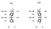
- FIG. 3 is a cross-sectional view along the warp according to the first embodiment.
- (A) represents sectional drawing in 1U and 1L in FIG. 1
- (b) is sectional drawing in 2U and 2L in FIG.
- the industrial fabric using a single weft double weft according to the present invention is characterized in that an upper surface side warp and a lower surface side warp are stacked one above the other and the upper and lower warps are woven by a plurality of wefts. In this way, by using the warp double weft single weave as the basic structure of the industrial fabric, the warp density can be increased.
- auxiliary wefts are arranged between the adjacent wefts.
- Such an auxiliary weft is characterized in that it is always arranged between the upper surface side warp and the lower surface side warp without interweaving with the upper surface side warp and the lower surface side warp.
- the present invention employs a warp double weft single weave as a basic structure to improve surface smoothness, but has a problem that rigidity is weakened.
- auxiliary weft that is not interwoven with the upper surface side warp and the lower surface side warp is arranged between the adjacent wefts.
- Such auxiliary wefts can achieve the same rigidity as a conventional weft double weave fabric. As described above, the surface smoothness is superior to the conventional fabric.
- an upper surface side floating yarn that interweaves only with the upper surface side warp may be arranged above the weft.
- a material having excellent rigidity such as PET is used for the weft to improve the rigidity. Therefore, the problem that a weft appears on the surface of a textile fabric arises. Therefore, the problem that the weft appears on the surface of the woven fabric can be solved by arranging the above-mentioned upper surface side float on the weft.
- a lower surface side float that interweaves only with the lower surface side warp may be arranged below the weft.
- the wire diameter of the auxiliary weft is larger than the wire diameter of the weft.
- the weft can be internally connected even when the upper surface side float is not used. Furthermore, by using auxiliary wefts having a large wire diameter, it is possible to control the movement of the upper and lower warps and to control the on-stack structure.
- the upper surface side warp and the upper surface side floating yarn in the industrial fabric according to the present invention are formed of a fluororesin, and the weft is formed of a yarn other than the fluororesin.
- a thread appearing on the surface side can be formed with a fluororesin having excellent antifouling property, and thus the antifouling effect can be sufficiently obtained.
- the number of yarns in the horizontal direction using a relatively expensive fluororesin can be reduced, so that the manufacturing cost can be reduced.
- a weft having a binding function can be formed of a yarn such as PET having a higher strength than a fluorine resin or the like.
- the weft as the binding yarn, it is possible to employ internal binding in which the binding yarn is not exposed on the surface. That is, there is an effect that it is possible to prevent the yarn of PET or the like from being exposed on the surface of the upper surface side fabric formed only of the fluorine-based resin or the like.
- the fluorine-based resin for forming the upper surface side warp and the upper surface side float of the industrial fabric according to the present invention any composite resin containing fluorine with high antifouling property may be used.
- PTFE polytetrafluoroethylene resin
- FEP tetrafluoroethylene-hexafluoropropylene copolymer
- PFA tetrafluoroethylene-perfluorovinyl ether copolymer
- PVDF polyvinylidene fluoride
- ETFE ethylene-tetrafluoroethylene copolymer
- ETFE is particularly suitable from the viewpoint of antifouling properties and cost.
- ETFE is more preferable in terms of flexibility to include a silicone resin in the fluororesin raw material (aqueous dispersion).
- various pigments are added to the fluororesin raw material (aqueous dispersion), the color of the fabric surface can be arbitrarily changed.
- the material of the yarn other than the fluororesin used for the weft of the industrial fabric according to the present invention is not particularly limited and can be freely selected depending on the properties desired for the industrial fabric.
- monofilaments, multifilaments, spun yarns, crimped and sublime processed textured yarns, bulky yarns, stretch yarns, processed yarns called taslan yarns, molding yarns, or twisted yarns Threads that are combined, for example, can be used.
- not only the circular cross-sectional shape of the yarn but also a square shape, a rectangular shape such as a star shape, a flat shape, an elliptical shape, and a hollow shape can be used.
- the properties of the yarn can be freely selected, and polyester, nylon, polyphenylene sulfide, polyvinylidene fluoride, polypropylene, aramid, polyetheretherketone, polyethylene naphthalate, cotton, wool, metal and the like can be used.
- copolymers and yarns with various substances blended or contained depending on the purpose may be used.
- the upper weft yarn is made of spun yarn, crimped or sublimated processed yarn, or a soft yarn with a large apparent wire diameter such as a moor yarn, the upper layer surface is likely to be covered with these yarns. It is preferable that the difference between the normal part and the joint part can be approached to the extent that it cannot be seen from the upper layer side.
- the yarn used in the present invention may be selected depending on the application. For example, in addition to monofilament, multifilament, spun yarn, crimped processing, bulky processing, etc., generally textured yarn, bulky yarn, stretch yarn, etc. Processed yarns that are called, or yarns that are combined by combining them can be used. Also, the cross-sectional shape of the yarn is not limited to a circle, but a short yarn such as a square shape or a star shape, an elliptical shape, or a hollow yarn can be used.
- the material of the yarn can also be freely selected, and polyester, polyamide, polyphenylene sulfide, polyvinylidene fluoride, polypro, aramid, polyetheretherketone, polyethylene naphthalate, polytetrafluoroethylene, cotton, wool, metal, etc. are used. it can.
- polyester, polyamide, polyphenylene sulfide, polyvinylidene fluoride, polypro, aramid, polyetheretherketone, polyethylene naphthalate, polytetrafluoroethylene, cotton, wool, metal, etc. are used.
- the arrangement ratio of the upper surface side float and / or the lower surface side float and the weft is preferably 1: 1.
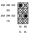
- FIG. 1 is a schematic plan view showing a complete structure according to Embodiment 1 of the present invention.
- the industrial fabric according to Embodiment 1 is a nonwoven fabric.
- the complete structure is the smallest repeating unit of the fabric structure, and the complete structure is connected vertically and horizontally to form the entire structure of the fabric.
- warps are indicated by Arabic numerals 1 and 2
- wefts are indicated by Arabic numerals 1 'to 4' with a dash
- U indicates a yarn of the upper surface side fabric
- L indicates a lower surface.
- the yarn is a side fabric.
- a weft functioning as a binding yarn is indicated by 2′W, for example, by adding W.
- the auxiliary weft is indicated by S and the float is indicated by f.
- the cross indicates that the upper side warp is located above the weft and forms a knuckle on the surface of the fabric.
- the ⁇ indicates that the lower side warp is located below the weft.
- Indicates that the upper surface side float is located above the upper surface side warp and forms a knuckle on the fabric surface
- ⁇ indicates that the lower surface side float is located below the lower surface side warp.
- the upper and lower warp yarns are arranged one above the other to form an on-stack structure.
- the nonwoven fabric fabric using a single weft double weft has an upper surface side warp (1U, 2U) and a lower surface side warp (1L, 2L) stacked one above the other.
- Such upper and lower warps are woven by a plurality of wefts (2′W, 4′W). Between the adjacent wefts (2′W, 4′W), the upper surface side warp (1U, 2U) and the lower surface side warp (1L, 2L) are not interwoven and always between the upper surface side warp and the lower surface side warp.
- Auxiliary wefts (1'S, 3'S) are arranged.
- the industrial fabric by the single weft double weft according to the present invention is woven only with the upper side warp (1U) above the weft (2'W, 4'W).
- Matching upper surface side floats (2′Uf, 4′Uf) are arranged.
- the upper surface side warp (1U) passes above the upper surface side floating yarn (2′Uf) and passes below the upper surface side floating yarn (4′Uf). Further, the upper surface side warp 1U passes below the weft 4'W.
- the lower surface side warp 1L passes above 2′W. Further, under the weft yarns (2′W, 4′W), lower surface side floating yarns (2′Lf, 4′Lf) that interweave only with the lower surface side warp yarns (1L) are arranged.
- the auxiliary weft yarns (1 ′S, 3 ′S) have a diameter of the weft yarns (2′W, 4′W) as shown in FIG. It is characterized by being larger than the diameter.
- the surface exposure degree of the warp is greatly improved, the rigidity of the fabric is also improved, and the movement of the upper and lower warps can be controlled.
- FIG. 2 (b) the nonwoven fabric fabric by the single weft double weft according to the present invention is woven only with the upper side warp (2U) above the weft (2'W, 4'W). Matching upper surface side floats (2′Uf, 4′Uf) are arranged.
- the upper surface side warp (2U) passes below the upper surface side floating yarn (2′Uf) and passes above the upper surface side floating yarn (4′Uf).
- the upper surface side warp (2U) passes below the weft (2′W).
- the lower surface side warp (2L) passes above the weft (4′W).
- lower surface side floating yarns (2′Lf, 4′Lf) that interweave only with the lower surface side warps (2L) are arranged.
- lower surface side floating yarns (2′Lf, 4′Lf) that interweave only with the lower surface side warps (2L) are arranged.
- the auxiliary weft yarns (1 ′S, 3 ′S) between the adjacent weft yarns (2′W, 4′W) is obtained. Things will be possible.
- the arrangement ratio of the upper surface side float and the lower surface side float and the weft is 1: 1.
- the weft (2′W, 4′W) is placed on the surface of the fabric. The problem of appearing can be solved.
- the woven fabric for nonwoven fabric according to Embodiment 1 can form knuckles that appear on the surface of the woven fabric only by using the upper surface side warps (1U, 2U), and can increase the knuckle density and smooth the surface. Can be improved.
Landscapes
- Engineering & Computer Science (AREA)
- Textile Engineering (AREA)
- Woven Fabrics (AREA)
Abstract
Description
ここで織物の特性の一つである剛性は、原料や浮遊成分等の目的物を保持、搬送する為に必要である。特に建材の製造工程、フィルタ用途等で重い原料や浮遊成分を取り扱うときには織物の必須特性として過酷な環境下でも好適に使用できる程度の剛性が要求される。寸法安定性は常に安定して織物を走行させる為に必要である。そして防汚性は、紙、不織布又は建材を常に安定した品質の製品として供給する為、又、効率の良いろ過、搬送を行うためにも重要な特性である。
更に、不織布に織物のワイヤーマークが転写しにくい表面平滑性に優れた織物、耐摩耗性を持ち合わせたもの、そして良好な不織布を製造するために必要な条件を長期間持続することのできる織物が要求されている。その他にも繊維支持性、不織布の歩留まりの向上、走行安定性等が要求されている。さらに近年では製造マシンが高速化しているため、それに伴い搬送用織物への要求も一段と厳しいものとなっている。
このような不織布用二層織物において、二重となっている緯糸を接結糸とすると、緯糸が上面側でナックルを形成するため、防汚効果のないPET等によって形成された糸が織物の表面に露出することになり、上面側織物をフッ素系樹脂で構成したことによる防汚効果が十分に得られないことになる。
このような問題点を解決するために、緯糸の本数を単に減らすと、織物の剛性が低下することになる。そのため、経糸密度を上げながら織物表面への経糸によるナックルの数を増やすことにより、表面性を向上させる技術が必要とされていた。
(1)少なくとも上面側経糸と下面側経糸が上下に積層し、それらを複数の緯糸によって織り合わせてなる経糸二重緯糸一重織による工業用織物において、隣接する前記緯糸の間に前記上面側経糸と下面側経糸と織り合うことなく常に上面側経糸と下面側経糸の間に配置される補助緯糸が配置されていることを特徴とする経糸二重緯糸一重織による工業用織物である。
(2)前記緯糸の上方に上面側経糸とのみ織り合う上面側浮糸が配置されていることを特徴とする上記(1)に記載された経糸二重緯糸一重織による工業用織物。
(3)前記緯糸の下方に下面側経糸とのみ織り合う下面側浮糸が配置されていることを特徴とする上記(1)又は(2)に記載された経糸二重緯糸一重織による工業用織物である。
(5)前記上面側経糸と上面側浮糸をフッ素樹脂により形成し、前記緯糸をフッ素樹脂以外の糸で形成したことを特徴とする上記(2)乃至(4)のいずれか一に記載された経糸二重緯糸一重織による工業用織物である。
(6)前記上面側浮糸及び\又は下面側浮糸と緯糸との配置比率が、1:1であることを特徴とする上記(2)乃至(5)のいずれか一に記載された経糸二重緯糸一重織による工業用織物である。
本発明に係る経糸二重緯糸一重織による工業用織物は、上面側経糸と下面側経糸が上下に積層させ、当該上下の経糸を複数の緯糸によって織り合わせてなることを特徴とする。このように経糸二重緯糸一重織を工業用織物の基本構造として採用することによって、経糸密度を上げることが可能となる。そのため、織物表面に表れるナックルを上面側経糸によって形成し、またかかるナックルの数を増やすことで表面平滑性を大幅に向上させることができる。
また本発明に係る工業用織物は、隣接する前記緯糸の間に補助緯糸が配置されている。かかる補助緯糸は、前記上面側経糸と下面側経糸と織り合うことなく常に上面側経糸と下面側経糸の間に配置される点に特徴を有する。本発明は、経糸二重緯糸一重織を基本構造として採用し、表面平滑性を向上させるものであるが、剛性が弱まるという問題が生じた。かかる問題点を解決するために隣接する緯糸の間に上面側経糸と下面側経糸と織り合わない特殊な補助緯糸を配置している。かかる補助緯糸により従来の緯糸二重織の織物と同じ剛性を得る事が可能となる。表面平滑性については従来の織物より優れていることは前述のとおりである。
また本発明に係る工業用織物は、前記緯糸の下方に下面側経糸とのみ織り合う下面側浮糸を配置しても良い。かかる浮糸を上面側経糸及び\又は下面側経糸と接触させることによって、経糸の移動を制御し、上下経糸が重なる位置を調整することができ、上下経糸のオンスタック構造を制御することが可能となった。
また本発明に係る工業用織物は、前記補助緯糸の線径を前記緯糸の線径よりも大きくすることが好ましい。補助緯糸の線径を大きくすることによって、経糸の表面露出度が大幅に向上する。又、線径の大きな補助緯糸を使用することによって、織物の剛性を大幅に向上させることできる。又、線径の大きな補助緯糸を使用することによって、上面側浮糸を使用しない場合であっても、緯糸を内部接結とすることができる。更に線径の大きな補助緯糸を使用することによって、上下経糸の移動を制御し、オンスタック構造を制御することが可能となった。
このような構造を採用することによって、防汚性に優れたフッ素系樹脂で表面側に表れる糸を形成することができるため、防汚性の効果を十分に得ることができる。また、比較的高価格であるフッ素系樹脂による横方向の糸の本数を減らすことができるため、製造コストを低廉化することができる。
また、このような構造を採用し、接結機能を有する緯糸をフッ素系樹脂等よりも強度の高いPET等の糸で形成することができる。緯糸を接結糸とすることによって、接結糸が表面に露出しない内部接結を採用することができる。すなわち、フッ素系樹脂等のみで形成された上面側織物の表面に、PET等の糸が露出することを防止することができるという効果が得られる。
本発明に係る工業用織物の上面側経糸及び上面側浮糸を形成するフッ素系樹脂としては、防汚性の高いフッ素を含有する複合樹脂であれば良いが、例えば、ポリテトラフロロエチレン樹脂(PTFE)、テトラフロロエチレン-ヘキサフロロプロピレン共重合体(FEP)、テトラフロロエチレン-パーフロロビニルエーテル共重合体(PFA)、ポリフッ化ビニリデン(PVDF)、エチレン-テトラフロロエチレン共重合体(ETFE)、エチレン-クロロトリフロロエチレン共重合体(ECTFE)から選ばれる少なくとも一つであることが好ましい。特にETFEが防汚性、コストの面から適している。
なお、フッ素樹脂原料(水分散液)中にシリコン樹脂を含ませておくと柔軟性の面で更に好ましい。又、フッ素樹脂原料(水分散液)中に各種顔料を添加しておくと、織物表面の色を任意に変えることができる。
実施形態1
図1は、本発明の実施形態1に係る完全組織を示す平面概念図である。実施形態1に係る工業用織物は不織布用織物である。ここで完全組織とは、織物組織の最小の繰り返し単位であって、この完全組織が上下左右につながって織物全体の組織が形成される。意匠図において、経糸はアラビア数字である1及び2で示し、緯糸はダッシュを付したアラビア数字である1’~4’で示し、Uは上面側織物の糸であることを示し、Lは下面側織物の糸であることを示す。又、接結糸として機能する緯糸はWを加えることで、例えば2’W等で示す。更に、補助緯糸はSで、浮糸はfで示す。
又、×印は上面側経糸が緯糸の上側に位置し織物表面にナックルを形成していることを示し、○印は下面側経糸が緯糸の下側に位置していることを示し、■印は上面側浮糸が上面側経糸の上側に位置し織物表面にナックルを形成していることを示し、□印は下面側浮糸が下面側経糸の下側に位置していることを示す。
上面側と下面側の経糸は上下に重なって配置され、オンスタック構造を形成している。
隣接する前記緯糸(2’W,4’W)の間には、上面側経糸(1U,2U)と下面側経糸(1L,2L)と織り合うことなく常に上面側経糸と下面側経糸の間に配置される補助緯糸(1’S,3’S)が配置されている。
次に図2(a)に示す如く、本発明に係る経糸二重緯糸一重織による工業用織物は、前記緯糸(2’W,4’W)の上方に上面側経糸(1U)とのみ織り合う上面側浮糸(2’Uf,4’Uf)が配置されている。又、上面側経糸(1U)は、上面側浮糸(2’Uf)の上側を通り、上面側浮糸(4’Uf)の下側を通っている。又、上面側経糸1Uは、緯糸4’Wの下側を通っている。下面側経糸1Lは、2’Wの上側を通っている。更に、前記緯糸(2’W,4’W)の下方に下面側経糸(1L)とのみ織り合う下面側浮糸(2’Lf,4’Lf)が配置されている。
次に図2(b)に示す如く、本発明に係る経糸二重緯糸一重織による不織布用織物は、前記緯糸(2’W,4’W)の上方に上面側経糸(2U)とのみ織り合う上面側浮糸(2’Uf,4’Uf)が配置されている。又、上面側経糸(2U)は、上面側浮糸(2’Uf)の下側を通り、上面側浮糸(4’Uf)の上側を通っている。又、上面側経糸(2U)は、緯糸(2’W)の下側を通っている。下面側経糸(2L)は、緯糸(4’W)の上側を通っている。更に、前記緯糸(2’W,4’W)の下方に下面側経糸(2L)とのみ織り合う下面側浮糸(2’Lf,4’Lf)が配置されている。
更に、前記緯糸(2’W,4’W)の下方に下面側経糸(2L)とのみ織り合う下面側浮糸(2’Lf,4’Lf)が配置されている。
ここで、上面側浮糸及び下面側浮糸と緯糸との配置比率は、1:1となっている。このように上面側浮糸(2’Uf,4’Uf)を緯糸(2’W,4’W)の上に配置することによって、緯糸(2’W、4’W)が織物の表面に表れるという問題を解決することができる。
実施形態1に係る不織布用織物は、上述のような構造を採用することにより、織物表面に表れるナックルを上面側経糸(1U,2U)のみによって形成し、ナックル密度を増やすことができ、表面平滑性を向上させることができる。
1L,2L 下面側経糸
2’W,4’W 緯糸
1’S,3’S 補助緯糸
2’Uf,4’Uf 上面側浮糸
2’Lf,4’Lf 下面側浮糸
Claims (5)
- 少なくとも上面側経糸と下面側経糸が上下に積層し、それらを複数の緯糸によって織り合わせてなる経糸二重緯糸一重織による工業用織物において、隣接する前記緯糸の間に前記上面側経糸と下面側経糸と織り合うことなく常に上面側経糸と下面側経糸の間に配置される補助緯糸が配置されていることを特徴とする経糸二重緯糸一重織による工業用織物。
- 前記緯糸の上方に上面側経糸とのみ織り合う上面側浮糸が配置されていることを特徴とする請求項1に記載された経糸二重緯糸一重織による工業用織物。
- 前記緯糸の下方に下面側経糸とのみ織り合う下面側浮糸が配置されていることを特徴とする請求項1又は2に記載された経糸二重緯糸一重織による工業用織物。
- 前記補助緯糸の線径が前記緯糸の線径よりも大きいことを特徴とする請求項1乃至3のいずれか一に記載された経糸二重緯糸一重織による工業用織物。
- 前記上面側経糸と上面側浮糸をフッ素樹脂により形成し、前記緯糸をフッ素樹脂以外の糸で形成したことを特徴とする請求項2乃至4のいずれか一に記載された経糸二重緯糸一重織による工業用織物。
Priority Applications (4)
| Application Number | Priority Date | Filing Date | Title |
|---|---|---|---|
| JP2015529432A JP5931292B2 (ja) | 2013-07-31 | 2014-06-03 | 経糸二重緯糸一重織による工業用織物 |
| US14/906,722 US10858766B2 (en) | 2013-07-31 | 2014-06-03 | Industrial fabric |
| CA2909142A CA2909142C (en) | 2013-07-31 | 2014-06-03 | Industrial fabric of double warps-single weft type |
| EP14832479.1A EP3029187A4 (en) | 2013-07-31 | 2014-06-03 | Industrial fabric by double-warp and single-weft woven fabric |
Applications Claiming Priority (2)
| Application Number | Priority Date | Filing Date | Title |
|---|---|---|---|
| JP2013159362 | 2013-07-31 | ||
| JP2013-159362 | 2013-07-31 |
Publications (1)
| Publication Number | Publication Date |
|---|---|
| WO2015015895A1 true WO2015015895A1 (ja) | 2015-02-05 |
Family
ID=52431440
Family Applications (1)
| Application Number | Title | Priority Date | Filing Date |
|---|---|---|---|
| PCT/JP2014/064698 Ceased WO2015015895A1 (ja) | 2013-07-31 | 2014-06-03 | 経糸二重緯糸一重織による工業用織物 |
Country Status (5)
| Country | Link |
|---|---|
| US (1) | US10858766B2 (ja) |
| EP (1) | EP3029187A4 (ja) |
| JP (1) | JP5931292B2 (ja) |
| CA (1) | CA2909142C (ja) |
| WO (1) | WO2015015895A1 (ja) |
Cited By (2)
| Publication number | Priority date | Publication date | Assignee | Title |
|---|---|---|---|---|
| CN109072518A (zh) * | 2016-04-27 | 2018-12-21 | 阿斯顿强生有限责任公司 | 工业织物、尤其传送带 |
| US20220042215A1 (en) * | 2016-04-27 | 2022-02-10 | AstenJohnson PGmbH | Industrial woven fabric |
Families Citing this family (1)
| Publication number | Priority date | Publication date | Assignee | Title |
|---|---|---|---|---|
| FI131402B1 (en) * | 2021-10-06 | 2025-04-02 | Valmet Technologies Inc | Industrial textiles |
Citations (7)
| Publication number | Priority date | Publication date | Assignee | Title |
|---|---|---|---|---|
| JP2002523653A (ja) * | 1998-08-31 | 2002-07-30 | アステンジョンソン・インコーポレイテッド | 縫い目領域に糸を追加した製紙用基布縫い目 |
| JP2003082594A (ja) * | 2001-09-12 | 2003-03-19 | Shikibo Ltd | 製紙機械用ドライヤーフェルト |
| JP2003247191A (ja) * | 2002-02-25 | 2003-09-05 | Ichikawa Woolen Textile Co Ltd | 抄紙用プレスフェルト用有端状ベース部材及び抄紙用プレスフェルト |
| JP3938817B2 (ja) | 1999-02-16 | 2007-06-27 | 日本フイルコン株式会社 | 工業用織物の接合用ループとこのループを用いた接合部 |
| WO2012140993A1 (ja) | 2011-04-11 | 2012-10-18 | 日本フイルコン株式会社 | 不織布用二層織物 |
| JP2013036157A (ja) * | 2011-07-12 | 2013-02-21 | Nippon Filcon Co Ltd | 工業用多層織物の接合用ループ構造 |
| JP2014141769A (ja) * | 2013-01-24 | 2014-08-07 | Ichikawa Co Ltd | 抄紙用プレスフェルト |
Family Cites Families (11)
| Publication number | Priority date | Publication date | Assignee | Title |
|---|---|---|---|---|
| DE2243478A1 (de) * | 1972-09-05 | 1974-03-28 | Muehlen Sohn Fa | Spezialgurt fuer wellpappenmaschinen |
| US3885603A (en) * | 1973-11-21 | 1975-05-27 | Creech Evans S | Papermaking fabric |
| JPS63145496A (ja) * | 1986-12-02 | 1988-06-17 | 日本フイルコン株式会社 | 製紙用多層織物 |
| US5199467A (en) * | 1990-06-06 | 1993-04-06 | Asten Group, Inc. | Papermakers fabric with stacked machine direction yarns |
| DE4232319A1 (de) * | 1992-09-26 | 1994-03-31 | Franz F Kufferath | Mehrlagiges Pressensieb für Naßpressen einer Papiermaschine |
| JP3844272B2 (ja) * | 1997-10-03 | 2006-11-08 | 株式会社小林製作所 | 建材製造用抄造ベルトおよび建材製造用トランスファーベルト |
| CA2274278A1 (en) * | 1998-06-12 | 1999-12-12 | Scapa Group Plc | Woven fabrics |
| DE19859582A1 (de) * | 1998-12-22 | 2000-06-29 | Voith Fabrics Heidenheim Gmbh | Drei- oder mehrlagiges Papiermaschinensieb in Form eines Verbundgewebes |
| US6379506B1 (en) * | 2000-10-05 | 2002-04-30 | Weavexx Corporation | Auto-joinable triple layer papermaker's forming fabric |
| US20040099328A1 (en) * | 2002-11-21 | 2004-05-27 | Rougvie David S. | Forming fabric with twinned top wefts and an extra layer of middle wefts |
| EP2698458B1 (en) * | 2011-04-11 | 2024-06-26 | Nippon Filcon Co., Ltd. | Multilayer weave for nonwoven fabric |
-
2014
- 2014-06-03 US US14/906,722 patent/US10858766B2/en not_active Expired - Fee Related
- 2014-06-03 EP EP14832479.1A patent/EP3029187A4/en not_active Withdrawn
- 2014-06-03 JP JP2015529432A patent/JP5931292B2/ja not_active Expired - Fee Related
- 2014-06-03 WO PCT/JP2014/064698 patent/WO2015015895A1/ja not_active Ceased
- 2014-06-03 CA CA2909142A patent/CA2909142C/en active Active
Patent Citations (7)
| Publication number | Priority date | Publication date | Assignee | Title |
|---|---|---|---|---|
| JP2002523653A (ja) * | 1998-08-31 | 2002-07-30 | アステンジョンソン・インコーポレイテッド | 縫い目領域に糸を追加した製紙用基布縫い目 |
| JP3938817B2 (ja) | 1999-02-16 | 2007-06-27 | 日本フイルコン株式会社 | 工業用織物の接合用ループとこのループを用いた接合部 |
| JP2003082594A (ja) * | 2001-09-12 | 2003-03-19 | Shikibo Ltd | 製紙機械用ドライヤーフェルト |
| JP2003247191A (ja) * | 2002-02-25 | 2003-09-05 | Ichikawa Woolen Textile Co Ltd | 抄紙用プレスフェルト用有端状ベース部材及び抄紙用プレスフェルト |
| WO2012140993A1 (ja) | 2011-04-11 | 2012-10-18 | 日本フイルコン株式会社 | 不織布用二層織物 |
| JP2013036157A (ja) * | 2011-07-12 | 2013-02-21 | Nippon Filcon Co Ltd | 工業用多層織物の接合用ループ構造 |
| JP2014141769A (ja) * | 2013-01-24 | 2014-08-07 | Ichikawa Co Ltd | 抄紙用プレスフェルト |
Non-Patent Citations (1)
| Title |
|---|
| See also references of EP3029187A4 |
Cited By (3)
| Publication number | Priority date | Publication date | Assignee | Title |
|---|---|---|---|---|
| CN109072518A (zh) * | 2016-04-27 | 2018-12-21 | 阿斯顿强生有限责任公司 | 工业织物、尤其传送带 |
| US20220042215A1 (en) * | 2016-04-27 | 2022-02-10 | AstenJohnson PGmbH | Industrial woven fabric |
| US12065767B2 (en) * | 2016-04-27 | 2024-08-20 | AstenJohnson PGmbH | Industrial woven fabric |
Also Published As
| Publication number | Publication date |
|---|---|
| CA2909142A1 (en) | 2015-02-05 |
| JP5931292B2 (ja) | 2016-06-08 |
| JPWO2015015895A1 (ja) | 2017-03-02 |
| US20160160405A1 (en) | 2016-06-09 |
| US10858766B2 (en) | 2020-12-08 |
| CA2909142C (en) | 2021-01-12 |
| EP3029187A1 (en) | 2016-06-08 |
| EP3029187A4 (en) | 2017-05-10 |
Similar Documents
| Publication | Publication Date | Title |
|---|---|---|
| JP5749796B2 (ja) | 不織布用二層織物 | |
| JP4819477B2 (ja) | 工業用二層織物 | |
| JP6280325B2 (ja) | 工業用二層織物 | |
| US7343938B2 (en) | Industrial two-layer fabric | |
| DK2626455T3 (en) | Two-ply woven fabric with the warp yarn loops compound | |
| JPWO2009044913A1 (ja) | 工業用二層織物 | |
| US10145064B2 (en) | High stability warp dryer fabric | |
| JP5931292B2 (ja) | 経糸二重緯糸一重織による工業用織物 | |
| JP5711946B2 (ja) | 工業用二層織物 | |
| EP3631064B1 (en) | High stability stacked warp yarn dryer fabric with long warp floats | |
| JP5280160B2 (ja) | 絞り緯糸を配置した工業用多層織物 | |
| JP2006507425A5 (ja) | ||
| JP4573168B2 (ja) | 工業用二層織物 | |
| JP2013501153A (ja) | 繊維質ウェブ材料を製造するためのフォーミングファブリック | |
| CN108966664B (zh) | 工业用双层织物 | |
| JP4743780B2 (ja) | 工業用二層織物 | |
| JP5856349B2 (ja) | 工業用二層織物 | |
| JP4570090B2 (ja) | 工業用二層織物 | |
| JP4684849B2 (ja) | 工業用二層織物 | |
| JP2017053067A (ja) | 抄紙用織物 | |
| EP2626455B1 (en) | Two-layer woven fabric with warp thread joining loops |
Legal Events
| Date | Code | Title | Description |
|---|---|---|---|
| 121 | Ep: the epo has been informed by wipo that ep was designated in this application |
Ref document number: 14832479 Country of ref document: EP Kind code of ref document: A1 |
|
| ENP | Entry into the national phase |
Ref document number: 2015529432 Country of ref document: JP Kind code of ref document: A |
|
| ENP | Entry into the national phase |
Ref document number: 2909142 Country of ref document: CA |
|
| WWE | Wipo information: entry into national phase |
Ref document number: 2014832479 Country of ref document: EP |
|
| WWE | Wipo information: entry into national phase |
Ref document number: 14906722 Country of ref document: US |
|
| NENP | Non-entry into the national phase |
Ref country code: DE |