WO2015016220A1 - 高炉の改修方法 - Google Patents
高炉の改修方法 Download PDFInfo
- Publication number
- WO2015016220A1 WO2015016220A1 PCT/JP2014/069944 JP2014069944W WO2015016220A1 WO 2015016220 A1 WO2015016220 A1 WO 2015016220A1 JP 2014069944 W JP2014069944 W JP 2014069944W WO 2015016220 A1 WO2015016220 A1 WO 2015016220A1
- Authority
- WO
- WIPO (PCT)
- Prior art keywords
- foundation
- furnace body
- new
- level
- blast furnace
- Prior art date
- Legal status (The legal status is an assumption and is not a legal conclusion. Google has not performed a legal analysis and makes no representation as to the accuracy of the status listed.)
- Ceased
Links
Images


Classifications
-
- C—CHEMISTRY; METALLURGY
- C21—METALLURGY OF IRON
- C21B—MANUFACTURE OF IRON OR STEEL
- C21B7/00—Blast furnaces
Definitions
- the present invention relates to a method for repairing a blast furnace, and more particularly to a method for repairing a blast furnace in which removal of an old furnace body / old furnace body and construction of a new furnace body / new furnace body can be performed in a short period of time.
- the blast furnace furnace is refurbished by the so-called ring block method, in which the furnace block is removed from the foundation as a ring block, and the ring block is assembled at another site and loaded onto the foundation.
- the method is adopted.
- a large block method has been developed in which the ring block is enlarged and the blast furnace is divided into about four huge ring blocks (see Patent Document 1).
- the old furnace body to be removed and the ring block of the new furnace body that has been carried in are sequentially suspended by a jack installed in the blast furnace furnace, and are pulled out from the block on the furnace bottom side to be removed.
- the furnace bottom portion of the old furnace body has a large weight of the bottom residue that has been cooled and solidified after being blown off, and the total weight may reach, for example, 8000 tons, which makes it difficult to lift it.
- a blast furnace bottom disassembly method has been proposed in which such a heavy furnace bottom portion is removed without lifting (see Patent Document 2).
- the foundation is divided into a plurality of long sections extending in the pull-out direction, and the sections are sequentially cut horizontally to repack the sliding plate and the filler. After repacking the compartments, slide on the sliding plate and pull out only in the horizontal direction. According to such a method, even a huge furnace bottom portion having a weight exceeding 8000 tons can be removed and carried as a ring block. These technologies have shortened the blast furnace repair period.
- Patent Document 4 As a method for constructing a high-rise structure of plant equipment, a technique has been proposed in which the apparatus main body and the surrounding frame are collectively loaded onto the foundation (see Patent Document 4).
- the lower part of the apparatus is set as a separate body, and the apparatus main body and the frame are shrunk and transported by the amount of the separate lower apparatus. Then, after the apparatus main body and the frame that have been contracted are installed on the foundation, they are lifted and extended, and the lower apparatus separately transported is assembled to complete the apparatus main body. Therefore, it can be said that the technique of patent document 4 is similar to the large block construction method in a blast furnace.
- Patent Document 4 the technology is intended for transportation by ship or vehicle, and does not assume a huge structure such as a blast furnace. Furthermore, although patent document 4 has the description about the installation which uses a special folding frame, there is no description regarding removal of an old structure.
- JP 2006-283183 A Japanese Patent No. 4300309 Japanese Patent Laid-Open No. 52-13406 Japanese Patent Laid-Open No. 58-106036
- each ring block is lifted by the furnace body so that the furnace body is necessary for removing and carrying in the furnace body. It is necessary to dismantle or reconstruct separately, which is a problem in shortening the construction period. Alternatively, it may be possible to divert the old furnace body as it is to the new furnace body, but in this case, the problem is that the expansion of the furnace capacity of the new furnace body is limited to avoid interference with the old furnace body. There is.
- Patent Literature 3 does not update the furnace body so that it cannot be applied to the blast furnace renewal accompanied by the expansion of the furnace body volume.
- Patent Document 4 described above since the assumed device is small enough to be transported by ship or vehicle, it cannot be applied to blast furnace renewal as it is, and work can be performed by expanding / contracting the frame or attaching / detaching the lower device. This is not suitable for shortening the repair period.
- An object of the present invention is to provide a blast furnace refurbishment method capable of removing an old furnace body / old furnace body and constructing a new furnace body / new furnace body in a short period of time.
- the present invention relates to a blast furnace refurbishing method for refurbishing a blast furnace having a furnace body and a furnace body installed on a field foundation, wherein the blast furnace is in operation and a new furnace different from the field foundation
- a new furnace body construction process for constructing a new foundation and a new furnace body and a new furnace body on the new foundation at the body construction site, and cutting the field foundation up and down to form an old furnace body and an old furnace
- the old blast furnace remains in operation, and the new furnace body and the new furnace body are placed on the new foundation at a new furnace body construction place different from the blast furnace installation place. Construction is done.
- the old furnace body drawing process and the new furnace body taking process are carried out to remove the old furnace body and the old furnace body from the field foundation, It can be replaced with the new furnace body and the new furnace body.
- the removed old furnace body and old furnace body can be appropriately dismantled in a state in which the new blast furnace is restarted at another old furnace body dismantling location. Accordingly, in the present invention, the blast furnace repair period can be shortened to about 50 to 70 days.
- each ring block can be manufactured and disassembled at a location different from the foundation, but the old furnace body can be split, lifted and removed, and the new furnace body It was necessary to carry on, lift and connect the ring block on the foundation. In this case, a blast furnace renovation period of about 80 to 120 days was required.
- the main work on the foundation of the blast furnace installation site is limited to the old furnace body drawing process and the new furnace body taking process, so that the repair period of the blast furnace can be greatly shortened. .
- the furnace body can be disassembled and the new furnace body can be disassembled together by replacing the furnace body and the furnace body together, which also shortens the work period.
- the equipment (various facilities, piping wiring, etc.) installed between the old furnace body and the old furnace body must be pulled out of the foundation as it is installed. Can do.
- the equipment installed between the new furnace body and the new furnace body can be pre-equipped in the new furnace body construction process and can be collectively loaded onto the foundation. In these respects, the repair period can be shortened.
- the old furnace body is replaced with the new furnace body simultaneously with the replacement of the old furnace body and the new furnace body.
- the new furnace body Even in the case of expansion, there is no restriction on the size of the old furnace body.
- a large new furnace body that does not fit in the old furnace body can be handled by constructing a new furnace body suitable for this, and the degree of freedom can be dramatically increased when expanding the furnace capacity. Can do.
- the new furnace body taking-in process since the new furnace body to be transported is supported by the new furnace body so that it can be transported integrally in a stable state, the process can be performed safely.
- a restoration foundation is formed on the upper surface of the lower portion of the foundation, and the new foundation is taken into the upper surface of the restoration foundation together with the new furnace body and the new furnace body.
- the restoration foundation even if the upper surface of the lower part of the foundation is rough or rough due to cutting during the foundation dividing process or work in the old furnace body drawing process, it can be covered with the restoration foundation. Yes, the top surface of the restoration foundation can be reconstructed as having high smoothness. For this reason, if a sliding structure or the like of the take-in transport device is installed on the upper surface of the restoration foundation, the new furnace body can be taken in with high accuracy and stability.
- an intake transfer device that linearly extends from the new furnace body construction place to the field foundation is used, and in the old furnace body drawing step, the new furnace is constructed from the field foundation.
- the take-up transport device and the drawer transport device are each between a pair of sliding plates. It is desirable to have a sliding structure using a solid lubrication type low friction lining.
- the old furnace body extraction device can share part of the part from the field foundation to the direction change position, for example, with the intake transport device described above.
- the present invention is not limited to the drawer transport device and the intake transport device that share a part of the transport path. The present invention may be configured such that the drawer transport device and the take-in transport device are independent of each other.
- the transfer device for the drawer should change the direction in the middle of the transfer device to extend in the cross direction, so that the old furnace body dismantling location is different from the new furnace building location. And avoid interference at the work place.
- the old furnace body and the old furnace body are disassembled after being pulled out, so there is no problem even if deformation or the like occurs, and there is no problem even if the direction is changed in the drawer transport apparatus.
- the present invention is not limited to the one in which the take-in transport device is linear and the drawer transport device changes the direction in the crossing direction in the middle.
- the present invention may be configured such that the drawer transport device is linear and the take-in transport device changes direction in the crossing direction in the middle.
- the drawer transport device and the intake transport device may each be configured to change direction.
- the take-up transport device may be configured to change the direction in the crossing direction in the middle of the transport path
- the draw-out transport device may be configured to change the direction in the crossing direction from the midway of the take-in transport device.
- the common part of the transfer route extends from the blast furnace installation location
- the transfer device for taking in the crossing direction from the end to the new furnace build location extends from the end to the opposite side of the old furnace It is also possible to use a configuration in which a drawer conveying device that extends toward the dismantling place extends.
- each of the drawer transport device and the take-in transport device may have a linear configuration.
- the drawer transport device and the intake transport device need to be independent from each other.
- the drawer transport device extends linearly to one of the on-site foundations, and the transport for capture in the other direction.
- a configuration in which the device extends can be used.
- the angle formed by the drawer transport device and the take-in transport device is not limited to 180 ° (lined up on the same line) or 90 °, but may be configured to have an angle of 45 ° or 60 °. . This is because in the present invention, since the furnace body is also transported integrally, there is no restriction on the angle through which the furnace body can pass.
- the conveyance of a new foundation, a new furnace body, and a new furnace body rod is a sliding plate type sliding which makes a pair of sliding plates slide mutually. This can be done by sliding the sliding plates in the structure.
- a mechanical structure such as a wheel or roller
- the part receiving the concentrated load of the mechanical structure is deformed or broken, thereby impairing the function. May be difficult to carry.
- a large load can be distributed and received on a wide sliding surface, and local deformation is unlikely to occur because the sliding surface is continuous. Therefore, even a huge new furnace body and a new furnace body can be reliably transported.
- a solid lubrication type low friction lining between a pair of sliding plates, the mutual frictional properties can be further reduced, and smooth and highly accurate conveyance can be carried out. Even if the new blast furnace is transported, it will not be damaged.
- a solid lubrication type low friction lining a solid lubricant, for example, a fine powder solid lubricant such as tetrafluoroethylene resin (PTFE), molybdenum disulfide, graphite, etc., is preferably fixed on the surface of the substrate. It is.
- PTFE tetrafluoroethylene resin
- These sliding structures are not limited to the transfer device used in the new furnace body take-in process, but may be used in the draw-out transfer device used in the old furnace body take-out process.
- the following mounts are installed to secure a sliding structure along the transport path, and transport using these Make work possible.
- extracting crosses from the 1st movement path
- a second moving path extending along the first moving path, a pulling rack that can move along the first moving path, a branch moving rack that can move along the second moving path, and a ground along the second moving path.
- a concave portion that accommodates the branch moving frame, wherein the first movement path is continuous from the upper surface of the drawer frame to the upper surface of the lower part of the foundation, and the height of the sliding surface is level.
- a sliding structure set to L1 a sliding structure formed between the lower surface of the drawer base and the ground, and the height of the sliding surface set to level L2, and the upper surface of the branch moving base And the sliding surface height is set to the level L2.
- the second moving path is formed between the lower surface of the branch moving frame and the bottom surface of the recess, and the height of the sliding surface is set at level L3.
- the transfer device includes a third movement path extending from the new foundation toward the field foundation, and a loading platform that is movable along the third movement path and supports the new foundation.
- a support member installed in the recess in the middle of the third movement path, the third movement path is formed between the lower surface of the take-in gantry and the ground,
- a sliding structure that is continuous to the vicinity of the lower part of the foundation via the upper surface of the support member, and the height of the sliding surface is set to the level L2
- the upper surface of the take-up gantry, and the new foundation A sliding structure formed between the lower surface and the height of the sliding surface is set to level L4;
- a sliding structure formed between the upper surface of the foundation and the lower surface of the new foundation, and the height of the sliding surface is set to the level L4, and the height of the sliding surface of the sliding structure Can be set such that level L4> level L1> level L2> level L3.
- the old furnace body or the upper part of the foundation is pulled out from the field foundation with the sliding structure of level L1, and then transported by using the drawer base with the sliding structure of level L2 until the subsequent direction change.
- the movement of only the old furnace body or the upper part of the foundation is suppressed to a short distance, and the drawer base can be used for the movement of a long distance, so that smooth and stable conveyance can be performed.
- the branch moving base is moved with a sliding structure of level L3 lower than level L2, the old furnace body or the upper part of the base can be placed together with the drawer base on the upper surface of the branch moving base, and the direction change can be performed smoothly. Can do.
- extracting is a crossing direction from the 1st movement path
- a second moving path extending from the first moving path to the second moving path, and the first moving path extends from the upper surface of the pulling rack.
- the take-in transport device has a structure, the third moving path extending from the new foundation toward the field foundation, and the taking-in apparatus that is movable along the third moving path and supports the new foundation.
- the third movement path is formed between the lower surface of the take-in gantry and the ground, continues to the vicinity of the lower portion of the foundation, and the height of the sliding surface is the level.
- a sliding structure set at L2 and a sliding structure formed between the upper surface of the take-in stand and the lower surface of the new foundation, and the height of the sliding surface is set at level L4;
- a sliding structure formed between the upper surface of the restoration foundation and the lower surface of the new foundation, and the height of the sliding surface is set to the level L4, and the sliding surface of the sliding structure
- the height may be level L4> level L1> level L2.
- the effects described in the previous section can be basically obtained, and the drawer of the old furnace body or the upper part of the foundation can be implemented only with the drawer base that slides with the sliding structure of level L2.
- the above-described branching frame and the recessed portion can be omitted.
- drawing-out crosses from the 1st movement path
- a second moving path extending along the second moving path and installed on the ground, a branch moving pedestal movable along the branch pedestal, along the first moving path and the An intermediate frame connected to the field foundation and the branch frame, and the first movement path is continuous from the upper surface of the branch movement frame to the upper surface of the lower part of the foundation via the upper surface of the intermediate frame, And the height of the sliding surface is set to level L1, and the second movement path is formed between the lower surface of the branch moving frame and the upper surface of the branch frame, and A sliding structure where the height of the moving surface is set to level L3 '
- the take-in transport device includes a third movement path extending from the new foundation toward the field foundation, a construction platform that supports the new foundation, and the branching in the middle of the third movement path.
- An auxiliary gantry installed on the gantry and the intermediate gantry, and the third movement path is formed between the lower surface of the new foundation and the upper surface of the building gantry, It has a sliding structure that continues to the upper surface of the restoration foundation via the upper surface and the height of the sliding surface is set to the level L4, and the height of the sliding surface of the sliding structure is level L4. > Level L1> Level L3 ′.
- the old furnace body or the upper part of the foundation is directly slid by the level L1 sliding mechanism and moved to the position where the direction is changed as it is. it can.
- the old furnace body or the upper part of the foundation can be placed on the upper surface of the branch moving stand, and the direction change can be performed smoothly. Can do.
- the new furnace body or new foundation can be adjusted and slid with the sliding structure of level L4, and it can be loaded to the field foundation as it is. At this time, by using a sliding structure of level L4 higher than level L1 for taking in the new blast furnace and the new foundation, it is possible to take in the upper surface of the restoration foundation.
- the take-up transport device has a guide groove that is continuous in the transport direction on the fixed side, a guide block that engages with the guide groove on the moving side, and the guide block is on the moving side. It is desirable to be installed at two places before and after the traveling direction.
- the vertical load applied to the moving side of the entire blast furnace is not affected by the engagement of the guide groove and the guide block. Because of the heavy weight, the guide block cannot get over the step in the guide groove. For this reason, the guide block is maintained in the guide groove and the guide is continued, and the moving side can be moved only in a predetermined transport direction. Thereby, the stability and high accuracy of conveyance can be ensured.
- the take-up transport device has an accuracy of a horizontal error of 3 mm or less per 1 m of movement.
- the new foundation, the new furnace body and the new furnace body in the above-mentioned new furnace body take-in process are transported with high accuracy and high stability, and the new furnace body and the new furnace body on the new foundation Deformation and the like that occur in the bag can be sufficiently suppressed, and highly accurate and safe conveyance can be performed.
- the repair period of the blast furnace is mainly the old furnace body drawing process and the new furnace body taking process.
- the construction period can be limited, and the repair period can be greatly shortened. Therefore, according to the present invention, it is possible to provide a blast furnace refurbishing method capable of removing an old furnace body / old furnace body and constructing a new furnace body / new furnace body in a short period of time.
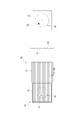
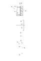
- the flowchart which shows the outline
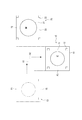
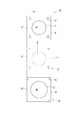
- the top view which shows arrangement
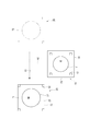
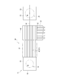
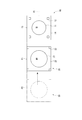
- the top view which shows the old furnace body extraction process of the said 1st Embodiment.
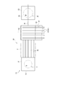
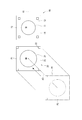
- the top view which shows the new furnace body taking-in process of the said 1st Embodiment.
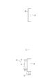
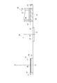
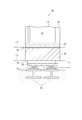
- the elevational view which shows the cutting
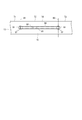
- the expanded elevation view which shows the cutting operation
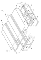
- the expansion perspective view which shows the cutting
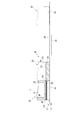
- the elevation view which shows the conveying apparatus used at the old furnace body extraction process of the said 1st Embodiment.
- the top view which shows the sliding structure of the level L1 used at the old furnace body extraction process of the said 1st Embodiment.
- the top view which shows the sliding structure of the level L2 used at the old furnace body extraction process of the said 1st Embodiment.
- the top view which shows the sliding structure of the level L3 used at the old furnace body extraction process of the said 1st Embodiment.
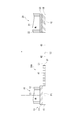
- the expansion perspective view which shows the principal part of the conveying apparatus used at the old furnace body extraction process of the said 1st Embodiment. Sectional drawing which shows the principal part of the conveying apparatus used at the old furnace body extraction process of the said 1st Embodiment.
- the expanded sectional view which shows the principal part of the conveying apparatus used at the old furnace body extraction process of the said 1st Embodiment.
- the top view which shows the principal part of the conveying apparatus used at the old furnace body extraction process of the said 1st Embodiment.
- the elevation view which shows the 1st conveyance operation
- the elevation view which shows the 2nd conveyance operation
- the top view which shows the traction apparatus used for the conveying apparatus of the said 1st Embodiment.
- the top view which shows the old furnace body extraction process of 4th Embodiment of this invention The top view which shows the new furnace body taking-in process of the said 4th Embodiment.
- the top view which shows the old furnace body extraction process of 5th Embodiment of this invention The top view which shows the new furnace body taking-in process of the said 5th Embodiment.
- the top view which shows the new furnace body taking-in process of the said 6th Embodiment. The top view which shows the old furnace body extraction process of 7th Embodiment of this invention.
- Sectional drawing which shows the conveyance apparatus for taking in available in the said 4th Embodiment and the said 5th Embodiment.
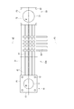
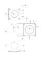
- FIG. 1 to FIG. 4 Each figure from FIG. 1 to FIG. 4 includes an outline of the blast furnace renovation process executed in the present embodiment (FIG. 1), a plan layout of work places used for refurbishment (FIG. 2), and an old furnace body drawing process (FIG. 1). 3) and a new furnace body taking-in process (FIG. 4) are shown.
- the blast furnace (old blast furnace 10) to be repaired in the present embodiment is installed at the blast furnace installation place P1.
- the old furnace body 11 and the old furnace body 12 are constructed on the field foundation 13 at the blast furnace installation place P1.
- the site foundation 13 is a plane rectangle, and a new furnace construction site P2 is set on an axis A1 orthogonal to the midpoint of one side.
- a new blast furnace 20 including a new furnace body 21 and a new furnace body rod 22 is constructed on the upper surface of the new foundation 23 in a new furnace body construction step S2 (see FIG. 1) described later.
- the old furnace body dismantling place P3 is set on the axis A2 extending in the orthogonal direction from the intermediate position with respect to the axis A1 connecting the new furnace body construction place P2 and the blast furnace installation place P1.
- the new blast furnace is constructed at the new blast furnace construction site P2 in the state where the operation at the old blast furnace 10 installed at the blast furnace installation location P1 (old blast furnace operation S1) continues.
- the body construction step S2 is started, and a new furnace body 21 and a new furnace body rod 22 to be the new blast furnace 20 are constructed on the new foundation 23.
- the furnace capacity of the new furnace body 21 is larger than that of the old furnace body 11. Therefore, the span of the new furnace shell 22 is expanded from the span of the old furnace shell 12.
- the new blast furnace 20 on the new foundation 23 includes incidental equipment such as control equipment and wiring piping in addition to the new furnace body 21 and the new furnace body 22 which are basic structures. Equipment is outfitted. By increasing the outfitting rate in this process, it is possible to reduce the work required for preparation of the new furnace body taking-in process S6 or new blast furnace operation S7 to be carried out later at the blast furnace installation place P1, and promote the shortening of the work period. .
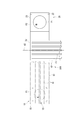
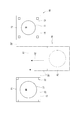
- the old blast furnace 10 is blown off S4, and then the old furnace body extraction step S5 is carried out, and the foundation upper part 14 on which the old blast furnace 10 including the old furnace body 11 and the old furnace body rod 12 is placed is mounted. Then, it is transported to the old furnace body dismantling place P3. As shown in FIG. 3, in the old furnace body drawing step S5, the foundation upper part 14 on which the old blast furnace 10 is placed is pulled out in the direction of the axis A1, and the direction is changed and moved along the axis A2, to the old furnace body disassembly place P3. Transport. During this time, the new furnace body construction step S2 is continued.
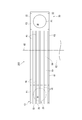
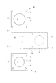
- a new furnace body take-in step S6 is performed, and in the new furnace body construction step S2, the new foundation 23 on which the new blast furnace 20 is mounted is moved in the direction of the axis A1, and the upper part of the foundation 14 and the old blast furnace 10 takes in on the base 15 which has been removed.
- the new blast furnace 20 is taken into the foundation lower part 15, pipe wiring is connected to the new furnace body 21 and the new furnace body rod 22 to complete the new blast furnace 20. Then, the blast furnace is fired and the new blast furnace operation S7 by the new blast furnace 20 is started.
- the old furnace body dismantling process S8 is performed in the old furnace body dismantling place P3 and sequentially dismantled.
- the new blast furnace operation S7 is started separately at the blast furnace installation place P1, and the old furnace body disassembly step S8 can be performed independently of the operation of the blast furnace, and can be gradually advanced according to an arbitrary schedule.
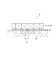
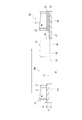
- FIG. 5 shows details of the basic division step S3 in the present embodiment.
- the field foundation 13 installed at the blast furnace installation place P1 is horizontally cut at the level L1 and divided into the foundation upper part 14 and the foundation lower part 15.
- An old blast furnace 10 (having an old furnace body 11 and an old furnace body 12) is constructed on the field foundation 13, and the divided foundation upper part 14 is horizontally moved integrally with the old blast furnace 10 constructed on the upper surface.
- the foundation lower part 15 is left fixed at the blast furnace installation place P1.
- each boundary (B1, B2,...) Is drilled with a drill to form a through hole 91 that penetrates the field foundation 13 in the direction of the axis A1. Then, a guide member 92 such as an H-shaped steel is installed in the through hole 91, and the wire saw 93 is held at the height of the upper flange and the lower flange.
- the wire saw 93 is mounted so as to go around the two through holes 91 at the positions of the boundaries B1 and B2, for example, so that the material of the cutting section T2 sandwiched between the boundaries B1 and B2 (the bricks constituting the site foundation 13) ) Can be cut horizontally.
- the field foundation 13 is divided into the foundation upper part 14 and the foundation lower part 15 in the cutting section T2.
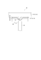
- a cavity 94 is formed between the foundation upper portion 14 and the foundation lower portion 15 in the trace where the cut material having a predetermined thickness is removed. Even if the cavity 94 is formed in the cutting section T2, the adjacent cutting sections T1 and T3 are not cut, so that the base upper part 14 is maintained at a predetermined interval with respect to the base lower part 15.
- the fixed side sliding plate 81, the moving side sliding plate 82 and the high pack anchor 95 are installed in the cavity 94.
- the fixed-side sliding plate 81 is laid on the bottom surface of the cavity 94, that is, the upper surface of the foundation lower portion 15.
- a stainless alloy or the like having a low friction coefficient is used for the fixed-side sliding plate 81.
- the moving side sliding plate 82 is installed on the upper surface of the fixed side sliding plate 81.
- a low-friction lining 83 containing a solid lubricant is stretched on the moving-side sliding plate 82 on the surface facing the fixed-side sliding plate 81.
- a solid lubricant for example, a fine powder such as tetrafluoroethylene resin (PTFE), molybdenum disulfide, graphite, or the like fixed to the surface of the substrate can be used.
- PTFE tetrafluoroethylene resin
- Commercially available Pillar Fluoro Gold PILLAR No. 4801 can be used.
- the high pack anchor 95 is a tough flexible bag body having a length corresponding to that of the moving side sliding plate 82 and knitted with aramid resin fibers, and is disposed on the upper surface of the moving side sliding plate 82. Is done. Then, by filling the inside with grout such as cement slurry, the upper surface of the high pack anchor 95 is brought into pressure contact with the ceiling surface of the cavity 94, that is, the bottom surface of the foundation upper portion 14. When the grout is solidified in this state, the base upper portion 14 is supported by the high pack anchor 95, that is, the load on the base upper portion 14 is transferred via the high pack anchor 95, the moving side sliding plate 82 and the fixed side sliding plate 81. It can be transmitted to the base lower part 15.
- the adjacent cutting sections T3 and T1 are subsequently cut.
- the above-described operation is sequentially performed in each cutting section, so that finally all the cutting sections, that is, the entire site foundation 13 are divided into the upper base portion 14 and the lower base portion 15.
- the moving side sliding plate 82 and the fixed side sliding plate 81 installed between the foundation upper part 14 and the foundation lower part 15 constitute a part of the conveying device used in the old furnace body drawing process S5 described later. .
- the drawer conveying device 30 used in the next old furnace body drawing step S5 is also installed.
- the drawer conveying device 30 is a drawer that is movable along the axis A ⁇ b> 1 (see FIG. 3) from the vicinity of the site foundation 13 in order to perform the drawing work (see FIG. 3) in the old furnace body drawing step S ⁇ b> 5.
- the gantry 31 and the branching gantry 32 that can move along the axis A2 (see FIG. 3) from the middle of the moving path of the drawer gantry 31 are provided.
- the drawer base 31 is a flat base formed of a steel frame or the like, and a sliding structure 42 is installed between the lower surface and the ground.
- the upper surface of the drawer base 31 is set to the same height as the upper surface of the base lower part 15, and a sliding structure 41 is provided continuously from the upper surface of the drawer base 31 to the upper surface of the base lower part 15.
- the sliding surface height of the sliding structure 41 is set to level L1
- the sliding surface height of the sliding structure 42 is set to level L2.
- the branch moving mount 32 is a flat mount formed of a steel frame or the like, and is installed in a recess 33 formed in the ground in the direction of the axis A2.
- One end of the recess 33 is arranged in a path connecting the blast furnace installation place P1 and the new furnace body construction place P2, and the other end is arranged in the old furnace body disassembly place P3.
- a sliding structure 43 is installed between the bottom surface of the concave portion 33 and the lower surface of the branching moving frame 32.
- the sliding surface height of the sliding structure 43 is set to level L3.
- the upper surface of the branch moving mount 32 is set to the same height as the ground.
- Most of the sliding structure 42 described above is installed on the ground, but a part thereof is installed on the upper surface of the branching moving mount 32.
- the sliding structure 41 provided on the upper surface of the drawer base 31 uses the fixed-side sliding plate 81 described in FIG. 7 and the moving-side sliding plate 82 on which a low-friction lining 83 is stretched. Configured.
- the fixed-side sliding plate 81 of the sliding structure 41 is continuously installed from the upper surface of the base lower portion 15 to the upper surface of the drawer base 31.
- the moving side sliding plate 82 of the sliding structure 41 is installed on the lower surface of the foundation upper part 14 and slides with respect to the fixed side sliding plate 81 of the sliding structure 41. With such a sliding structure 41, the foundation upper part 14 can be pulled out horizontally along the sliding surface of the level L1 and placed on the upper surface of the drawer base 31.
- the sliding structure 42 on which the drawer base 31 (see FIG. 8) slides is similar to the above-described sliding structure 41 and the fixed-side sliding plate 81 described in FIG.
- the moving side sliding plate 82 is provided with a frictional lining 83.
- the fixed-side sliding plate 81 of the sliding structure 42 is continuously installed from the vicinity of the base lower part 15 to the upper surface of the branching moving frame 32.
- the moving side sliding plate 82 of the sliding structure 42 is installed on the lower surface of the drawer base 31 and slides with respect to the fixed side sliding plate 81 of the sliding structure 42. With such a sliding structure 42, the drawer base 31 on which the foundation upper part 14 is placed can be pulled out horizontally along the sliding surface of the level L2 and placed on the upper surface of the branching movement base 32.
- the sliding structure 43 on which the branch moving base 32 slides is similar to the above-described sliding structure 41 in that the fixed-side sliding plate 81 described in FIG.
- the moving side sliding plate 82 is stretched.
- the fixed sliding plate 81 of the sliding structure 43 is continuously installed from one end to the other end of the recess 33.
- the moving-side sliding plate 82 of the sliding structure 43 is installed on the lower surface of the branch moving frame 32 and slides with respect to the fixed-side sliding plate 81 of the sliding structure 43.
- the sliding structure 42 is installed on the ground, and the sliding structure 43 is installed on the bottom surface of the recess 33.
- the ground and the bottom surface on which these sliding structures 42 and 43 are installed are ground improved so that sufficient rigidity can be obtained to withstand a heavy load such as a furnace body of a blast furnace.
- a reinforcing steel material 34 (see FIG. 12) for receiving the sliding structures 42 and 43 is installed on the ground and the bottom surface.
- a reinforcing steel material 34 having a flat upper surface such as H-shaped steel is embedded, and level adjustment using a long steel plate is performed on the upper surface of the reinforcing steel material 34.
- Rail 96 is installed, and a fixed-side sliding plate 81 of the sliding structure 42 is supported on the upper surface of the rail 96 at the level L2.
- the rail 96 is appropriately provided with a shim between the upper surfaces of the reinforcing steel members 34, so that straight lines are made along the longitudinal direction of the rails 96 and the upper surfaces of all the rails 96 arranged in parallel. Is adjusted to be level L2.
- reinforcing steel material 34 and rail 96 are also installed on the bottom surface of the recess 33 where the sliding structure 43 is installed, and the fixed-side sliding plate 81 of the sliding structure 43 is formed by the reinforcing steel material 34 and the rail 96. Is supported at level L3.
- the sliding structure 42 is continuously installed from the ground contacting the side surface of the foundation lower part 15 to the upper surface of the branch moving mount 32.
- the fixed side sliding plate 81 of the sliding structure 42 is cut at the edge portion of the branch moving frame 32 (dotted line portion in FIG. 12), and the ground It separates from the sliding structure 42 outside the recess 33 remaining on the top.
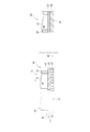
- the guide structure 50 is installed on the sliding structures 42 and 43 in the drawer base 31 and the branch moving base 32, respectively.
- the above-described reinforcing steel material 34 is embedded in the ground, and a drawer stand 31 is supported thereon.
- a sliding structure 42 is installed between the upper surface of the reinforcing steel material 34 and the lower surface of the drawer base 31.
- a guide groove 51 that is continuous in a straight line along the longitudinal direction of the sliding structure 42 (in the direction of the axis A ⁇ b> 1 in FIG. 2) is formed in the center of the sliding structures 42 described above.
- the guide groove 51 has a depth reaching from the sliding structure 42 to the reinforcing steel material 34.
- a steel guide block 52 that can be accommodated in the guide groove 51 is installed on the lower surface of the drawer base 31.
- the cross-sectional shapes of the guide block 52 and the guide groove 51 the upper portion is rectangular, but the lower portion is semicircular, and a predetermined gap necessary for sliding is ensured between the respective contour shapes.
- the cross-sectional shape may be other shapes.
- the guide block 52 is fixed to two positions on the lower surface of the drawer base 31 on the front side and the rear side in the movement direction.
- two guide blocks 52 are engaged with a guide groove 51 that is continuous in a straight line, so that the direction of the drawer base 31 is the continuous direction of the guide groove 51, that is, the direction of conveyance by the sliding structure 42. It is accurately maintained at a certain axis A1.
- the engagement between the guide block 52 and the guide groove 51 is maintained even during movement, so that the drawer base 31 is correctly regulated in the transport direction. It is possible to accurately convey the target position.
- the vertical load applied to the drawer base 31 is a large weight of the entire blast furnace, so that the guide block 52 gets over the step of the guide groove 51. I ca n’t go outside. Therefore, the guide block 52 is maintained in the guide groove 51 and the guide is continued, and the drawer base 31 can be moved only in a predetermined transport direction without meandering.
- the base upper part 14 and its upper part 14 and its upper part 14 are driven by driving the base upper part 14 in the direction of the axis A1 (see FIG. 3) and sliding the sliding structure 41 at the level L1.
- the old blast furnace 10 constructed above is integrally pulled out from the upper surface of the lower base 15 and moved to the upper surface of the drawer base 31.
- the drawer base 31 is driven in the direction of the axis A1 (see FIG. 3), and the sliding structure 42 at the level L2 is slid to thereby pull out the drawer base 31.
- the foundation upper part 14 and the old blast furnace 10 placed thereon are moved together to the upper surface of the branching moving frame 32.
- the branch moving mount 32 is driven in the direction of the axis A2 (see FIG. 3), and the sliding structure 43 at the level L3 is slid to be placed on the branch moving mount 32.
- the drawer base 31, the upper base 14 and the old blast furnace 10 are moved together to the old furnace body dismantling place P3 (see FIG. 3).
- the old blast furnace 10 at the blast furnace installation place P1 can be transferred to the old furnace body dismantling place P3.
- the old furnace body drawing step S5 shown in FIG. 3 can be completed.
- traction from the front side in the traveling direction or propulsion from the rear side may be employed.
- a configuration in which a wire is connected to the foundation upper part 14 and pulled by a winch from the new furnace body construction place P2 side can be used.
- a hydraulic jack such as a center hole jack or other drive source can be used.
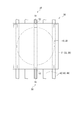
- the towing device 70 has four center hole jacks 71 installed in parallel on the ground near the new furnace body construction site P2, and the wire 72 to be pulled by each is on-site along the axis A1 which is the drawing and conveying direction. It extends to the base 13.
- the base upper part 14 of the field foundation 13 is formed with through holes penetrating both side surfaces in the direction of the axis A1, and the wire 72 is opposite to the new furnace body construction site P2 of the base upper part 14 through the through holes. Is pulled out to the side.
- a reaction force receiving member 73 is inserted into the leading end of the drawn wire 72 and firmly fixed.
- a horizontal traction force is applied to the base upper portion 14 by pulling each wire 72 in a state where the four center hole jacks 71 are synchronized, and the base upper portion 14 is supported by the support member 35. Is displaced with respect to the base lower portion 15, and thereby the first conveyance described above is performed.
- the traction force applied to the wire 72 is enormous because the weight of the foundation upper part 14 and the old furnace body 11 and the old furnace body rod 12 on the foundation upper part 14 is large. Thus, cracks or the like do not occur in the vicinity of the through hole of the base upper part 14 due to the load concentration.
- Such a traction device 70 is also used for the second and third transfer operations.
- a center hole jack 71 is installed on the ground near the new furnace body construction site P2, and the direction of the axis A1 The wire 72 extending in the direction is connected to the drawer base 31 via the reaction force receiving member 73 and pulled.
- a center hole jack 71 is installed at the old furnace body dismantling place P3, and a wire 72 extending in the direction of the axis A2 is provided. Then, it is connected to the branch moving mount 32 via the reaction force receiving member 73 and pulled.
- the take-in transport device 39 includes a take-in stand 38 that supports the new foundation 23, a sliding structure 44 that continues from the bottom of the take-in stand 38 to the front of the base lower portion 15, It has a sliding structure 45 installed between the upper surface of the loading stand 38 and the lower surface of the new foundation 23, and a sliding structure 46 installed on the upper surface of the foundation lower part 15.
- These sliding structures 44, 45, and 46 have the same configuration as the sliding structures 41 to 43 described above, that is, the fixed side sliding plate 81, the moving side sliding plate 82, and the low friction property shown in FIG.
- the lining 83 is provided, and each extends continuously in the direction of the axis A1 (see FIG. 4).
- the sliding structure 44 is formed between the lower surface of the take-in gantry 38 and the ground, and the fixed side formed on the ground is continuously installed up to the front of the base lower part 15. In the middle of the sliding structure 44, the recess 33 is left as described above. Therefore, a support member 35 is installed in the recess 33 to support the sliding structure 45 across the recess 33 over the entire surface.
- the sliding structure 44 may use a part of the sliding structure 42 left on the ground between the foundation lower part 15 and the recessed part 33.
- the sliding structure 44 under the take-in mount 38 is previously constructed when the take-in mount 38 is installed.
- the take-in stand 38 moves horizontally from the new furnace body construction site P2 to the front of the blast furnace installation site P1, together with the new foundation 23 and the new blast furnace 20 mounted on the upper surface thereof.
- the height of the sliding surface of the sliding structure 44 is the same level L2 as that of the sliding structure 42. However, when a part of the sliding structure 42 is not used, a different level may be used.
- the ground reinforcement see FIG. 12
- ground reinforcement by the reinforcing steel material 34 can be used as it is.
- the sliding structure 45 is installed between the lower surface of the new foundation 23 and the upper surface of the loading stand 38 when the new foundation 23 is previously set on the loading stand 38. With such a sliding structure 45, the new foundation 23 can move horizontally with respect to the take-in stand 38.
- the height of the sliding surface of the sliding structure 45 is level L4.
- the level L4 is set higher than the level L1 of the sliding structure 41 described above.
- the sliding structure 46 includes a fixed side installed on the upper surface of the foundation lower portion 15 and a moving side (new foundation 23 side) of the sliding structure 45 described above. Although the details will be described later, the new foundation 23 is moved horizontally with respect to the take-in stand 38 by the sliding structures 45 and 46 in a state where the take-in stand 38 is adjacent to the base lower portion 15. It is transferred to the upper surface of
- the height of the sliding surface of the sliding structure 46 is set to the same level L4 as that of the sliding structure 45.
- the recovery foundation 26 for supporting the sliding structure 46 is installed in the upper surface of the foundation lower part 15.
- the fixed-side sliding plate 81 (FIG. 7) of the sliding structure 41 installed in the foundation dividing step S3. See) is left. Therefore, the fixed side sliding plate 81 of the sliding structure 41 is removed. Furthermore, the upper surface of the foundation lower portion 15 exposed after removing the fixed-side sliding plate 81 of the sliding structure 41 is a surface formed by horizontal cutting with a wire saw in the foundation dividing step S3, so that unevenness remains. Absent. Therefore, the upper surface of the base lower part 15 is cut out over a predetermined thickness, and the upper surface of the base lower part 15 is made smooth.
- a restoration foundation 26 is installed on the upper surface of the smoothed foundation lower part 15.
- the restoration foundation 26 includes a pad 84 installed on the upper surface of the foundation lower portion 15, a pad liner 85 placed on the pad 84, and a base grout 86 that is filled around the pad 84 and solidifies.
- a rail 96 for level adjustment similar to the upper surface of the reinforcing steel material 34 for ground reinforcement described above is installed, and the sliding structure 46 is installed on the upper surface of the rail 96. Is done.
- the pad 84 supports the fixed-side sliding plate 81 of the sliding structure 46 via the pad liner 85 and the rail 96, and the base lower portion 15 is spaced at a predetermined interval along the continuous direction of the fixed-side sliding plate 81. Arranged on the top surface of the substrate.
- the pad 84 can support the weight of the fixed-side sliding plate 81, but when the operator deforms the pad 84, the sliding surface of the fixed-side sliding plate 81 is adjusted to the level L4.
- the Such a pad 84 can support the weight of the fixed-side sliding plate 81, can be deformed at the installation stage, and can be used as long as it is cured by the passage of time from the installation or by a predetermined process. For example, a highly viscous grout or a thermosetting synthetic resin material can be used.
- the pad liner 85 is a shim, that is, a plate made of a steel plate, and the upper surface height of the rail 96 is aligned to a predetermined level by adding and removing a plurality of sheets, whereby the upper surface, that is, the sliding surface of the fixed-side sliding plate 81 is made.
- the level is adjusted to L4.
- the base grout 86 is made of concrete or the like, and is filled around the pad 84 after the height of the fixed side sliding plate 81 is adjusted.
- the base grout 86 is filled from the upper surface of the base lower portion 15 to a height at which the side surface of the rail 96 is covered, and the upper surface side of the rail 96 and the fixed side sliding plate 81 are held in an exposed state.
- the restoration foundation 26 is completed. With this restoration foundation 26, the fixed-side sliding plate 81 is adjusted to the height previously adjusted, that is, the sliding surface is at the level L4. Held in.
- the fixed side sliding plate 81 of the sliding structure 46 is supported by the restoration foundation 26 so as to be at the level L4 of the sliding surface, and the new foundation 23 is transferred thereon.
- the moving-side sliding plate 82 on the lower surface of the new foundation 23 installed as the sliding structure 45 is fixed to the upper surface of the lower portion 15 of the foundation via the low friction lining 83 stretched on the surface thereof.
- the sliding plate 81 is brought into sliding contact with the sliding plate 81, thereby obtaining the function as the sliding structure 46.
- the new foundation 23 and the new blast furnace 20 can be moved sequentially by the sliding structures 44, 45, 46 described above, and can be conveyed to the lower part of the foundation 15, thereby constituting a take-up conveyance device 39.
- the sliding structures 44, 45, and 46 are adjusted with high accuracy so that the horizontal error is 3 mm or less per 1 m of movement.
- a guide structure 50 similar to that of the pull-out transport device 30 is provided between the fixed side of the sliding structures 44, 45, 46 and the new base 23 and the take-in mount 38, respectively. It is installed and the posture during transportation is stabilized, and the new blast furnace 20 can be carried into an accurate position on the foundation lower part 15.
- the loading stand 38 at the new furnace body construction site P2 is driven in the direction of the axis A1 (see FIG. 3), and the sliding structure 44 at the level L2 is moved.
- the new blast furnace 20, the new foundation 23, and the loading stand 38 are horizontally moved together and conveyed from the new furnace body construction location P ⁇ b> 2 to a position adjacent to the foundation lower portion 15.
- the new foundation 23 on the take-in mount 38 adjacent to the foundation lower portion 15 is driven in the direction of the axis A1 (see FIG. 3), and the level L4
- the new blast furnace 20 and the new foundation 23 are horizontally moved integrally by sliding the sliding structure 45 located at the same position, and gradually transferred to the sliding structure 46 at the same level L4, from the upper surface of the take-in stand 38. Then, it is conveyed to the upper surface of the restoration foundation 26 formed on the foundation lower part 15.
- the new foundation 23 and the new blast furnace 20 are installed on the foundation lower part 15, and the taking-in of the new blast furnace 20 to the blast furnace installation place P1 is completed.
- the traction stand 38 and the new foundation 23 may be driven by traction or propulsion, and the traction device 70 used in the old furnace body extraction step S5 described above.
- a configuration similar to that shown in FIGS. 18 and 19 can be used.
- the taken-in new foundation 23 and restoration foundation 26 are securely fixed by the new blast furnace operation S7.
- fixing can be performed by pouring mortar having high fluidity between the new foundation 23 and the restoration foundation 26 and solidifying the mortar. Such fixing can be performed in a short time in parallel with the connection of peripheral equipment of the new blast furnace 20 and the like.
- the new blast furnace 20 is placed on the new foundation 23 at the new furnace body construction place P2, which is different from the blast furnace installation place P1, while the old blast furnace 10 remains in operation (old blast furnace operation S1).
- a furnace body 21 and a new furnace body 22 can be constructed.
- the foundation upper part 14 and the old blast furnace 10 can be removed and replaced with the new foundation 23 and the new blast furnace 20 that have been constructed previously.
- the removed old blast furnace 10 can be appropriately dismantled in a state where the new blast furnace 20 is restarted (new blast furnace operation S7) at another old furnace body dismantling place P3. Therefore, in this embodiment, the blast furnace repair period can be shortened to about 50 to 70 days.
- the replacement of the old furnace body 11 and the new furnace body 21 is not limited to the replacement of the base upper part 14 and the new foundation 23, and the old furnace body 12 and the new furnace body 22 are collectively replaced.
- Equipment such as various facilities and piping wiring
- installed between the old furnace body 11 and the old furnace body rod 12 can be pulled out of the foundation while attached as it is.
- the equipment installed between the new furnace body 21 and the new furnace body rod 22 can be pre-equipped in the new furnace body construction step S2 and can be taken in on the base in a lump.
- the construction period can be shortened.
- the old furnace body 12 is replaced with the new furnace body 22 at the same time as the replacement of the old furnace body 11 and the new furnace body 21, even when the furnace capacity of the new furnace body is greatly expanded.
- the size of the old furnace shell 12 is not limited. That is, even a large new furnace body 21 that does not fit in the old furnace body 12 can be dealt with by constructing a new furnace body 22 in accordance with this in advance, and there is a degree of freedom in expanding the furnace capacity. Can be dramatically improved.
- the new furnace body taking-in process S6 since the new furnace body 21 to be transported is supported by the new furnace body rod 22 and can be transported integrally in a stable state, the same process can be performed safely.
- the transfer device 39 for transfer transfers the new furnace body taking-in step S6, that is, the new foundation 23 and the new blast furnace 20 at the new furnace body construction place P2 to the base lower part 15 of the blast furnace installation place P1. Can be transported to.
- the take-in transfer device 39 linear the transfer can be performed with a minimum drive without changing the direction, and the new furnace body 21 and the new furnace body 22 on the new foundation 23 can be transported. The possibility of causing deformation or the like can be reduced, and safe conveyance can be performed.
- the sliding structures 44, 45, 46 each use a fixed sliding plate 81 over a long distance as the fixed side (lower side) and a short moving side slide as the moving side.
- the moving plate 82 is formed of a stainless steel alloy having a low friction coefficient and the moving side sliding plate 82 is provided with a low friction lining 83 containing a solid lubricant. can do. For this reason, even if the new foundation 23 to be transported and the new blast furnace 20 including the new furnace body 21 and the new furnace body rod 22 have a large weight exceeding, for example, 8000 tons, they can be transported without any trouble.
- the sliding structures 44, 45, and 46 are adjusted with high accuracy so that the horizontal error is 3 mm or less per 1 m of movement. For this reason, the deformation
- a guide groove 51 is formed on the fixed side of the sliding structures 44, 45, 46, and a guide block 52 is formed on the lower surface of the new base 23 and the take-up stand 38 on the moving side.
- the guide structure 50 Since the guide structure 50 is simple, the guide does not come off due to the large weight of the new blast furnace 20, the posture during transportation is stabilized, and the new blast furnace 20 can be It can be carried in to any position.
- the new blast furnace 20 and the new foundation 23 are transported by the horizontal movement of the take-up stand 38 at the level L2 by the sliding structure 44, and from the upper surface of the take-in stand 38 to the lower base 15 Therefore, the new blast furnace 20 and the new foundation 23 are not moved up and down at all and the repair work period can be shortened accordingly.
- the drawer transportation device 30 can transport the old furnace body extraction step S5, that is, the foundation upper part 14 and the old blast furnace 10 at the blast furnace installation place P1 to the old furnace body disassembly place P3.
- the drawer transport device 30 is an L-shaped route that changes its direction in the middle, and in particular, a part of the route, that is, a portion from the vicinity of the field foundation 13 to the recess 33 is overlapped with the transport device 39 for loading.
- the ground that is maintained and reinforced to withstand the load can be shared and used effectively.
- the withdrawal conveying device 30 shares a part of the route with the intake conveying device 39 (in the direction of the axis A1), and extends in the crossing direction (in the direction of the axis A2) from the middle thereof, thereby dismantling the old furnace body P3 can be set at a place different from the new furnace body construction place P2, and interference at the work place can be avoided. Since the old furnace body 11 and the old furnace body 12 are disassembled after being pulled out, there is no problem even if deformation or the like occurs. There is no problem.
- the drawer transport device 30 can be realized by placing the drawer base 31 that moves in the direction of the axis A1 on the branch moving base 32 that moves in the direction of the axis A2 when changing the direction from the direction of the axis A1 to the direction of the axis A2. Therefore, a special mechanism for changing the direction is unnecessary, and the work can be performed smoothly and reliably. Further, the concave moving part 32 in the direction of the axis A1 to which the branch moving base 32 should move is formed so that the branch moving base 32 can move at a level L3 that is one step lower than the level L2 at which the drawer base 31 moves. A configuration for placing the drawer base 31 on the branch moving base 32 can be realized without using the special device.
- the conveyance of the old blast furnace 10 and the upper base 14 is moved horizontally to the level L1 of the sliding structure 41 from the upper surface of the lower base 15 to the upper surface of the drawer base 31, and the sliding structure 42 of the drawer base 31.
- the conveyance in the old furnace body extraction step S5 can be stabilized and highly accurate.
- the sliding structures 41, 42, 43 use a fixed sliding plate 81 over a long distance as the fixed side (lower side), and a short moving side slide as the moving side.
- the plates 82 are formed of a stainless alloy or the like having a low friction coefficient, and the moving side sliding plate 82 is provided with a low friction lining 83 containing a solid lubricant, so that the friction coefficient with respect to the fixed side is remarkably reduced. be able to. For this reason, even if the basic upper part 14 to be transported and the old blast furnace 10 including the old furnace body 11 and the old furnace body rod 12 have a large weight exceeding, for example, 8000 tons, they can be transported without any trouble.
- the base upper portion 14 and the old furnace body 11 and the old furnace body 12 are moved up and down in order to perform cutting sequentially in a plurality of cutting sections and fill the high pack anchor. While the old blast furnace operation S ⁇ b> 1 continues, the field foundation 13 can be cut up and down, and the sliding structure 41 can be installed between the foundation upper part 14 and the foundation lower part 15.
- FIGS. 25 and 26 show a second embodiment of the present invention.
- the blast furnace is renovated according to the schematic progress shown in FIGS.
- the first embodiment described above is different in the configuration of the drawer conveying device 30A used in the old furnace body drawing step S5.
- the overlapping description is abbreviate
- the drawer transport device 30 (see FIG. 8) is formed on the ground in order to perform the third transport operation (transport in the direction of the axis A2 leading to the old furnace body dismantling place P3).
- the concave portion 33, the sliding structure 43 laid on the bottom surface thereof, and the branch moving stand 32 that moves in the concave portion 33 were used.
- the concave portion 33 and the branching movement frame 32 are omitted, and the third transport work is performed at the same level L2 as the second transport work.
- the drawer conveying device 30A includes the drawer base 31 and the sliding structures 41 and 42 similar to those of the first embodiment described above, the sliding structure 41 is level L1, and the sliding structure 42 is Level L2 is set.
- the sliding structure 42 is supported by the ground over its entire length and is reinforced by a reinforcing steel material 34 shown in FIG.
- the sliding structure 43 is installed on the ground at the level L2.
- the fixed sliding plates 81 intersect with each other in a grid pattern and are welded, and the upper surface, which is the sliding surface, is smoothed. Polished.
- the drawer base 31 is transported in the direction of the axis A1 using the sliding structure 42 by the second transporting operation, and reaches the intersection of the sliding structure 42 and the sliding structure 43. And in the 3rd conveyance work, drawer stand 31 is conveyed in the direction of axis A2 using sliding structure 43 from the intersection, and is sent to old furnace body demolition place P3.
- the same effect as that of the first embodiment described above can be obtained. Furthermore, in the drawer conveying apparatus 30A, it is not necessary to form the concave portion 33 in the ground, and therefore civil engineering work can be simplified. On the other hand, at the intersection of the sliding structure 42 and the sliding structure 43, it is necessary to weld each fixed side sliding plate 81 individually and to smoothly polish the upper surface which is the sliding surface. Therefore, it is desirable to select which of the first embodiment and the present embodiment is adopted as appropriate in consideration of the work load according to the site situation and the like.
- FIGS. 27 to 31 show a third embodiment of the present invention.
- the blast furnace is renovated according to the schematic progress shown in FIGS.
- the first embodiment described above is different in the configuration of the drawer transport device 30B used for the old furnace body pulling step S5 and the transfer device 39B used for the new furnace body pulling step S6.
- the overlapping description is abbreviate
- the drawer conveyance device 30B used in the old furnace body drawing step S5 will be described.
- the drawer transport device 30 corresponds to each of the sliding structures 41 (level L1) in the direction of the axis A1 in order to perform the first to third transport operations.
- the sliding structure 42 level L2 in the direction of the axis A1
- the sliding structure 43 level L3 in the direction of the axis A2.
- the upper and lower surfaces of the drawer base 31 are set to the level L1 and the level L2, and the level L3 is set below the level L2 by a predetermined height, that is, the recess 33 is formed and the sliding structure 43 is laid on the bottom surface thereof.
- the drawer base 31 was placed on the branch moving base 32 and the direction change in the direction of the axis A2 was realized.
- the drawer base 31 and the second transfer work are omitted, and the base upper part 14 and the old blast furnace 10 are moved from the base lower part 15 to the branch moving base 32 as the first transfer work.
- the branch moving platform 32 on which the upper base 14 and the old blast furnace 10 are placed is moved in the direction of the axis A2 at a level L3 ′ lower than the level L1.
- the drawer conveying device 30B of the present embodiment has the following configuration different from that of the first embodiment described above.
- an intermediate frame 61 is installed on the ground from the vicinity of the base lower part 15 toward the new furnace body construction place P2.
- the front end of the intermediate frame 61 on the side of the new furnace body construction place P2 is set to a position before the position where the direction is changed.
- a branch base 62 is installed on the ground from the position where the direction is changed to the old furnace body dismantling place P3 (see FIG. 3).
- a branch moving mount 32 is installed on the branch mount 62.
- a sliding structure 41 is installed between the upper surface of the foundation lower portion 15 and the lower surface of the foundation upper portion 14 as in the first embodiment, and the fixed side (fixed side sliding plate 81 shown in FIG. 7) It extends from the upper surface of the lower part 15 through the upper surface of the intermediate frame 61 to the upper surface of the branch moving frame 32.
- the height of the sliding surface of the sliding structure 41 is set to the same level L1 as in the first embodiment.
- a sliding structure 43 similar to that of the first embodiment is installed between the upper surface of the branching frame 62 and the lower surface of the branching movement frame 32.
- the height of the sliding surface of the sliding structure 43 is set to a level L3 ′ that is lower than the level L1 of the sliding structure 41 by the height of the branch moving frame 32.
- the sliding structure 43 is installed on the bottom surface of the recess 33 (see FIG. 8), and the sliding surface is at the level L3 lower than the ground surface.
- the level L3 ′ in the present embodiment is the ground level. Since it is the upper surface of the branch stand 62 installed on the top, it is higher than the ground. However, it is common in that the height of the branch moving mount 32 used for the direction change is lower than the previous height (level L2 in the first embodiment, level L1 in the present embodiment).
- the intake transport device 39B (see FIGS. 30 and 31) used in the new furnace body intake step S6 will be described.
- the take-in transport device 39 (see FIG. 21) includes the sliding structure 44 that slides the bottom surface side of the take-in mount 38 in order to perform the first transport work.
- the sliding structures 45 and 46 for sliding the new base 23 with respect to the upper surface of the take-in mount 38 and the upper surface of the restoration base 26 were provided.
- the first transfer operation for horizontally moving the take-in mount 38 is omitted, and a second transfer operation, that is, from above the mount installed at the new furnace body construction place P2,
- the foundation 23 and the new blast furnace 20 are moved horizontally as they are, and conveyed to the upper surface of the restoration foundation 26 in a single operation.
- the take-in transport device 39B of the present embodiment has the following configuration that is different from that of the first embodiment described above.
- a construction base 63 is installed on the ground, and the new foundation 23 for constructing the new blast furnace 20 is supported on the upper surface of the construction base 63.
- a sliding structure 45 having a sliding surface level L4 is installed.
- the sliding structures 41 and 43 on the upper surface remain.
- the auxiliary mounts 64 and 65 are installed on the intermediate mount 61 and the branch mount 62, and the height of the upper surface thereof is the same as that of the construction mount 63. Keep it like that.
- the restoration foundation 26 is formed on the upper surface of the foundation lower portion 15, and the height of the upper surface is the same as that of the construction platform 63. Then, the fixed side of the sliding structure 46 is laid from the upper surface of the restoration foundation 26 to the upper surfaces of the auxiliary mounts 65 and 64. As in the first embodiment, the sliding structure 46 shares the moving side of the sliding structure 45 formed on the lower surface of the new foundation 23 (see FIG. 23), and the sliding surface is at level L4. After laying, the upper surface of the construction base 63 is connected to the fixed side end of the sliding structure 45, and the upper surface is finished smoothly.
- the foundation upper part 14 and the old blast furnace 10 are transported from above the foundation lower part 15 onto the branch moving frame 32 using the sliding structure 41. Subsequently, the branch moving frame 32 is transported to the old furnace body dismantling place P3 (see FIG. 3) using the sliding structure 43.
- the new furnace body taking-in process S6 after installing the restoration foundation 26, the auxiliary racks 64 and 65, and the sliding structure 46, the new foundation 23 and the new blast furnace 20 are transported to the blast furnace installation place P1 at a stretch.
- the same effect as that of the first embodiment described above can be obtained.
- the second carrying work in the old furnace body drawing step S5 of the first embodiment described above is unnecessary, and the axis A1 direction at the level L1 is not required.
- a traction device 70 see FIGS. 18 and 19
- branch frame 62 and the branch moving frame 32 are used for the conveyance in the direction of the axis A2, the connection and polishing of a large number of intersections between the sliding structure 42 and the sliding structure 43 as in the second embodiment are performed. There is no need to do.
- the new foundation 23 is installed after the restoration foundation 26, the auxiliary racks 64 and 65, and the sliding structure 46 are installed. And the new blast furnace 20 can be conveyed at a stretch to the blast furnace installation place P1.
- the installation of facilities related to driving of the traction device 70 see FIGS. 18 and 19
- Work can be reduced including removal, and the construction period can be further shortened.
- the stability of the conveyance is high and the accuracy of the conveyance can be increased.
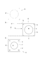
- [Fourth Embodiment] 32 and 33 show a fourth embodiment of the present invention.
- the blast furnace is repaired by the steps shown in FIG.
- it differs from the first to third embodiments described above in the planar arrangement of the blast furnace installation place P1, the new furnace body construction place P2, and the old furnace body disassembly place P3, and the drawer used for the old furnace body extraction step S5.
- the arrangement of the transfer path for intake and the transfer path for intake used for the new furnace body intake step S6 are also different.
- a new furnace body construction site P2 is installed in the direction of the axis A1 with respect to the blast furnace installation site P1, and the blast furnace installation site P1 and the new furnace body construction are installed.
- the old furnace body dismantling place P3 was installed on the axis A2 extending in the crossing direction from the middle of the place P2.
- the new furnace body construction place P2 and the old furnace body disassembly place P3 are arranged opposite to each other with respect to the arrangement of FIG. 2 described above.
- the extraction transport path 30 ′ from the blast furnace installation place P1 to the old furnace body dismantling place P3 is linearly configured, and the extraction from the new furnace body construction place P2 to the blast furnace installation place P1 is configured.
- the feeding transport path 39 ′ is configured in an L shape that branches in the crossing direction from the middle of the withdrawal transport path 30 ′.
- the conveyance is performed as follows.
- the old furnace body extraction step S5 as shown in FIG. 32, the field foundation 13 is divided at the blast furnace installation place P1, and the upper part 14 of the foundation or the old blast furnace 10 (the old furnace body 11 and the old furnace body 12) thereon is integrated.
- it is linearly moved to the old furnace body dismantling place P3 along the transport path 30 'for withdrawal.
- the new furnace body taking-in process S6 as shown in FIG. 33, the new blast furnace 20 (new furnace body 21 and new furnace body 22) constructed at the new furnace body construction site P2 is integrated with the new foundation 23.
- the blast furnace installation place P1 along the transfer route 39 ′ for intake.
- the take-in conveyance path 39 ′ the movement is first performed along the axis A2, and the direction is changed, and then the movement is performed along the axis A1.
- the specific mechanisms of the transport device in the pull-out transport path 30 ′ and the take-in transport path 39 ′ are the pull-out transport devices 30, 30A, 30B and the take-in transport devices 39, 39A of the above-described embodiments. , 39B can be used, and the configuration of the first embodiment (using levels L1 to L4), the second embodiment (using levels L1, L2, and L4), or the third embodiment described above. What is necessary is just to design suitably according to (utilizing level L1, L3 ', L4). Also according to this embodiment, the same effects as those of the first to third embodiments described above can be obtained. However, in each embodiment, the effect by the taking conveyance route being linear is not obtained.
- [Fifth Embodiment] 34 and 35 show a fifth embodiment of the present invention.
- the blast furnace is repaired by the steps shown in FIG.
- it differs from the first to third embodiments described above in the planar arrangement of the blast furnace installation place P1, the new furnace body construction place P2, and the old furnace body disassembly place P3, and the drawer used for the old furnace body extraction step S5.
- the arrangement of the transfer path for intake and the transfer path for intake used for the new furnace body intake step S6 are also different.
- the withdrawal conveyance path 30 ′ and the intake conveyance path 39 ′ are each configured to change the direction in the middle.
- the extraction conveyance path 30 ′ extends along the axis A1 from the blast furnace installation place P1, changes direction in the middle, and extends upward in the figure along the axis A2, and at the end thereof.
- Old furnace body dismantling place P3 is installed.
- the withdrawal conveyance path 30 ′ and the intake conveyance path 39 ′ are each configured to change direction in the middle, and the path extending along the axis A1 from the blast furnace installation location P1 is:
- the drawer transport path 30 'and the intake transport path 39' are shared.
- the conveyance is performed as follows.
- the old furnace body extraction step S5 as shown in FIG. 34, the field foundation 13 is divided at the blast furnace installation place P1, and the upper part 14 of the foundation or the old blast furnace 10 (the old furnace body 11 and the old furnace body 12) thereon is integrated.
- the blast furnace installation location P1 along the transport route 30 'for extraction.
- the withdrawal conveyance path 30 ′ first, the movement is performed along the axis A1, the direction is changed toward the old furnace body dismantling place P3, and then the movement is performed along the axis A2.
- the new furnace body loading step S6 as shown in FIG.
- the new blast furnace 20 (new furnace body 21 and new furnace body 22) constructed at the new furnace body construction site P2 is integrated with the new foundation 23. Then, it is moved to the blast furnace installation location P1 along the transfer path 39 ′ for intake. In the take-in conveyance path 39 ′, first, the movement is performed along the axis A2 (toward the old furnace body dismantling place P3), the direction is changed toward the blast furnace installation place P1, and then the movement is performed along the axis A1. .
- the specific mechanisms of the transport device in the pull-out transport path 30 ′ and the take-in transport path 39 ′ are the pull-out transport devices 30, 30A, 30B and the take-in transport devices 39, 39A of the above-described embodiments. , 39B can be used, and the configuration of the first embodiment (using levels L1 to L4), the second embodiment (using levels L1, L2, and L4), or the third embodiment described above. What is necessary is just to design suitably according to (utilizing level L1, L3 ', L4). Also according to this embodiment, the same effects as those of the first to third embodiments described above can be obtained.
- both the withdrawal conveyance path 30 ′ and the intake conveyance path 39 ′ change directions, the degree of freedom in selecting the installation locations of the new furnace body construction place P2 and the old furnace body removal place P3 is increased. It is expensive and can be easily applied to blast furnaces where the surrounding facilities are crowded.
- the drawer transport path 30 ′ and the take-in transport path 39 ′ can share the transport device at the shared part along the axis A1, and the part along the axis A2 is also arranged in a straight line.
- the conveying device such as the traction device 70 can be shared.
- the drawer transport devices 30, 30A, 30B, the take-in transport devices 39, 39B in the first to third embodiments described above, the pull-out transport path 30 ′ of the fourth embodiment or the fifth embodiment When the direction of the conveyance direction is changed halfway along the take-in conveyance path 39 ′, the direction conversion angle is not limited to 90 degrees, and may be 45 degrees, 60 degrees, or any other angle.
- the number of parts whose directions are changed in each of the conveyance paths such as the extraction conveyance path 30 ′ and the intake conveyance path 39 ′, that is, the number of times of the direction change in one conveyance path is not limited to 1, and is 2 or more. May be.
- FIG. 36 and 37 show a sixth embodiment of the present invention.
- the blast furnace is repaired by the steps shown in FIG.
- it differs from the first to third embodiments described above in the planar arrangement of the blast furnace installation place P1, the new furnace body construction place P2, and the old furnace body disassembly place P3, and the drawer used for the old furnace body extraction step S5.
- the arrangement of the transfer path for intake and the transfer path for intake used for the new furnace body intake step S6 are also different.
- the blast furnace installation place P1, the new furnace body construction place P2, and the old furnace body disassembly place P3 are arranged on a straight line along the axis A1.
- the new furnace body construction site P2 and the old furnace body dismantling site P3 are arranged on the opposite side with respect to the blast furnace installation site P1.
- the extraction transport path 30 ′ and the intake transport path 39 ′ are linearly configured.
- the extraction conveyance path 30 ′ and the intake conveyance path 39 ′ are installed on the opposite side with respect to the blast furnace installation place P1, and are configured to be independent from each other without a shared portion.
- the conveyance is performed as follows.
- the old furnace body extraction step S5 as shown in FIG. 36, the field foundation 13 is divided at the blast furnace installation place P1, and the upper part 14 of the foundation or the old blast furnace 10 (the old furnace body 11 and the old furnace body 12) thereon is integrated.
- the new furnace body dismantling place P3 along the transport path 30 'for withdrawal.
- the new furnace body loading step S6 as shown in FIG. 37, the new blast furnace 20 (new furnace body 21 and new furnace body 22) constructed at the new furnace body construction site P2 is integrated with the new foundation 23.
- it is linearly moved to the blast furnace installation location P1 along the intake transport path 39 ′.
- the specific mechanisms of the transport device in the pull-out transport path 30 ′ and the take-in transport path 39 ′ are the pull-out transport devices 30, 30A, 30B and the take-in transport devices 39, 39A of the above-described embodiments. , 39B can be used, and the configuration of the first embodiment (using levels L1 to L4), the second embodiment (using levels L1, L2, and L4), or the third embodiment described above. What is necessary is just to design suitably according to (utilizing level L1, L3 ', L4).
- the extraction transport path 30 ′ and the intake transport path 39 ′ are each linear and independent from each other.
- the structure (level L3, L3 ') for direction change like each embodiment mentioned above can be abbreviate
- FIG. 38 and 39 show a seventh embodiment of the present invention.
- the blast furnace is repaired by the steps shown in FIG.
- it differs from the first to third embodiments described above in the planar arrangement of the blast furnace installation place P1, the new furnace body construction place P2, and the old furnace body disassembly place P3, and the drawer used for the old furnace body extraction step S5.
- the arrangement of the transfer path for intake and the transfer path for intake used for the new furnace body intake step S6 are also different.
- the extraction transport path 30 ′ and the intake transport path 39 ′ are each configured linearly.
- the extraction conveyance path 30 ′ extends along the direction of the axis A1
- the intake conveyance path 39 ′ has an axis A3 (of the rectangular field foundation 13) that forms an angle of 45 degrees with respect to the axis A1. It extends along the diagonal direction.
- the old blast furnace 10 and the new blast furnace 20 can be transported in the same procedure as in the sixth embodiment described above. According to this embodiment, the same effect as that of the sixth embodiment described above can be obtained. Furthermore, the new furnace body construction site P2 is set at a position different from that of the sixth embodiment described above by installing the intake transport path 39 'along the axis A3 that forms an angle of 45 degrees with respect to the axis A1. it can. That is, from the relationship of the peripheral equipment of the blast furnace, the arrangement as in the above-described sixth embodiment, that is, the blast furnace installation place P1, the new furnace body construction place P2, and the old furnace body disassembly place P3 are aligned along the axis A1.
- the take-in conveyance path 39 ' is installed obliquely toward the place where the new furnace body construction site P2 can be installed (the axis A3 is 30 degrees, 60 degrees, 120 degrees, 135 degrees, etc. with respect to the axis A1). be able to.
- the field foundation 13 corresponds to an existing blast furnace foundation structure such as a reinforced concrete structure constructed on the ground of the blast furnace installation place P1.
- Such a field foundation 13 is divided into a foundation upper part 14 and a foundation lower part 15 in the foundation dividing step S3, and it is desirable to select the division position in consideration of the reinforcing bar structure inside the field foundation 13 and the like.
- a slab-like foundation structure that expands in a plane may be used, or a steel frame structure or a part thereof filled with a refractory filler such as castable may be used.
- the new foundation 23 is taken into the blast furnace installation place P1 and constitutes the foundation of the new blast furnace 20, and equipment such as cooling pipes and piping wiring necessary for the blast furnace function may be incorporated in advance. .
- Such installation of equipment on the new foundation 23 may be performed prior to the construction of the new furnace body 21 and the new furnace body rod 22 on the upper surface of the new foundation 23, or at the same time. May be.
- the drawer base 31, the branch moving base 32, the take-in base 38, the intermediate base 61, the branch base 62, and the construction base 63 are the base upper part 14 supported on the upper surface and the old blast furnace 10 or the new base 23.
- a steel frame structure can be used.
- the old blast furnace 10 and the foundation upper part 14 are only disassembled thereafter, so that the extraction conveyance devices 30, 30A, 30B are similar to the intake conveyance devices 39, 39B. High accuracy is not necessary.
- the drawer transport devices 30, 30A, 30B and the intake transport devices 39, 39B use the sliding structures 41 to 46.
- These are the fixed-side slide plate 81 and the movable-side slide shown in FIG.
- the fixed-side sliding plate 81 may be a plate-like member that is continuous in the transport direction, and the moving-side slide plate 82 is not limited to a plate that is continuous in the transport direction, but is intermittently arranged.
- a configuration in which a plurality of disk-shaped pads are arranged may be changed as appropriate if the desired sliding performance is obtained.
- the moving side sliding plate 82 is provided with the low friction lining 83, but this may be provided on the fixed side sliding plate 81 side, or The low-friction lining 83 is omitted, the fixed-side sliding plate 81 and the moving-side sliding plate 82 are brought into direct sliding contact, and a lubricant having high lubricity under a high load is supplied between them. Also good.
- the low-friction lining 83 is not limited to a solid lubricant, for example, a fine lubricant such as tetrafluoroethylene resin (PTFE), molybdenum disulfide, or graphite fixed to the surface of the substrate. It may be in the form of a film or film. Further, the low friction lining 83 may be omitted, and the solid lubricant may be dispersed in a viscous medium and supplied between the fixed side sliding plate 81 and the moving side sliding plate 82 as so-called grease.
- PTFE tetrafluoroethylene resin
- the above-described drawer transport devices 30, 30A, 30B and take-in transport devices 39, 39B are each provided with a guide structure 50 to improve the accuracy of the transport axis, but in the take-up transport devices 39, 39B, While such high accuracy is indispensable, the drawer conveying devices 30, 30 ⁇ / b> A, and 30 ⁇ / b> B may be less accurate. However, in order to perform safe conveyance, it is desirable to add a configuration for preventing any skew, and the configuration described in Patent Document 1 described above can be appropriately employed.
- the drawer transport devices 30, 30A, and 30B and the intake transport devices 39, 39A, and 39B are configured, and the height levels L1 to L4 are set in each.
- the first embodiment using levels L1 to L4
- the second embodiment using levels L1, L2, and L4
- the third embodiment using levels L1, L3 ′, and L4
- Similar height levels L1 to L4 are used in the extraction transport path 30 ′ and the intake transport path 39 ′ of the fourth to seventh embodiments.
- Specific values of these height levels L1 to L4 may be set as appropriate in implementation. Further, other levels may be added according to the intersection of the conveyance routes.
- the level L4 (the restoration foundation 26 on the upper surface of the smoothed foundation lower part 15). It is desirable to always carry out the setting of the level), that is, the maintenance of the upper surface of the lower portion 15 of the foundation to form the new restoration foundation 26. With such a restoration foundation 26, the new blast furnace 20 can be taken in smoothly.
- the configuration shown in FIG. 40 can be used when the take-in transport path 39 ′ corresponds to the level L4.
- the branch moving frame 32 is supported via a sliding structure 43. Similar to the structure of FIG. 12, the ground supporting the sliding structure 43 is reinforced with a reinforcing steel material 34.
- a take-up stand 38 is supported on the upper surface of the branch moving stand 32 via a sliding structure 42.
- a new foundation 23 is formed on the upper surface of the take-in stand 38 via a sliding structure 45, and a new blast furnace 20 including a new furnace body 21 and a new furnace body rod 22 is formed thereon.
- the sliding surface (sliding structure 43) of the branching gantry 32 is level L3
- the sliding surface (sliding structure 42) of the take-in gantry 38 is level L2
- Structure 45) can be at level L4.
- the present invention can be used as a method for repairing a blast furnace in which removal of an old furnace body / old furnace body and construction of a new furnace body / new furnace body are performed in a short period of time.
- Old blast furnace operation S2 ... New furnace body construction process S3 ... Basic division process S4 ... Blow stop S5 . Old furnace body withdrawal process S6 ; New furnace body take-in process S7 ... New blast furnace operation S8 ... Old furnace body dismantling process T1, T2, T3 ... Cutting section
Landscapes
- Engineering & Computer Science (AREA)
- Chemical & Material Sciences (AREA)
- Manufacturing & Machinery (AREA)
- Materials Engineering (AREA)
- Metallurgy (AREA)
- Organic Chemistry (AREA)
- Furnace Housings, Linings, Walls, And Ceilings (AREA)
- Conveying And Assembling Of Building Elements In Situ (AREA)
- Mechanical Engineering (AREA)
- General Engineering & Computer Science (AREA)
- Furnace Charging Or Discharging (AREA)
Abstract
Description
炉体の更新は、高炉設置場所の基礎上に構築されている旧炉体を撤去し、同基礎上に新たな炉体を構築することで行われる。
炉体の更新の際に、基礎上で旧炉体を解体し、その後、新炉体を構築すると、高炉の吹き止め期間が長くなり、一日あたり多額の経済的損失が生じる等の問題がある。
なかでも、リングブロックを大型化し、高炉を4つ程度の巨大なリングブロックに分割する大ブロック工法が開発されている(特許文献1参照)。
特許文献1の方法では、撤去する旧炉体および搬入された新炉体のリングブロックを、高炉櫓に設置したジャッキで順次吊り下げ、炉底側のブロックから側方へ引き出して撤去する。
ただし、旧炉体の炉底部分は、吹き止め後に冷却固化した炉底残滓の重量が大きく、全体重量が例えば8000トンにも及ぶ場合もあり、これを持ち上げることが困難となる。
特許文献2の方法では、基礎を引出方向に延びる複数の長尺区画に区分し、各区画に順次、基礎を水平に切断して摺動プレートと充填材とを詰め直す作業を行い、全ての区画の詰め直しができた後、摺動プレートで摺動させて水平方向にのみ引き出す。このような方法によれば、重量が8000トンを超える巨大な炉底部分についても、リングブロックとして撤去および搬入が可能となる。これらの技術により、高炉の改修工期短縮がなされている。
ただし、特許文献3の技術は、炉体を一括して取り扱うが、図面にも明らかなように、炉体櫓はそのまま残されており、炉体櫓の解体あるいは構築に関する記載はない。
これは、その当時の高炉の改修方法の技術水準では、炉本体(耐火物等の損耗)の寿命への対応が主であり、炉容の変更については僅かな拡大等を考慮する程度であったことから、改修にあたっては炉本体のみを解体および再構築すればよく、それにより炉体を支持する炉体櫓までの解体や再構築の必要はなく、工期および経済的な側面からも炉体櫓は流用されることが普通であったことによる。
この技術では、装置の下部を別体としておき、別体とされた下部装置の分、装置本体と架構とを縮めて搬送する。そして、縮めておいた装置本体と架構とを基礎上に設置したのち、これらを吊り上げて伸長させ、別途搬送した下部装置を組み込んで装置本体を完成させる。従って、特許文献4の技術は、高炉における大ブロック工法に類するものといえる。ただし、特許文献4にも記載されている通り、同技術は船舶・車両による運搬を想定したものであり、高炉のような巨大な構造物を想定したものではない。さらに、特許文献4には、特殊な折りたたみ式架構を用いる設置についての記載があるものの、旧構造物の撤去に関しての記載はない。
しかし、前述した特許文献1あるいは特許文献2のような大ブロック工法では、各リングブロックに対して撤去および搬入の作業が必要であり、これらの撤去および搬入のつど炉体櫓に吊り上げる作業も必要であり、改修工期短縮を図ることが難しい。
あるいは、旧炉体の炉体櫓をそのまま新炉体に流用することも考えられるが、この場合には旧炉体櫓との干渉を避けるべく新炉体の炉容拡大が制限されるという問題がある。
また、前述した特許文献4では、想定された装置が船舶・車両で運搬可能な程度の小型のものであるため、そのまま高炉の更新に適用できないとともに、架構の伸縮や下部装置の脱着などで作業が必要となり、改修工期短縮に適したものではない。
本発明の目的は、旧炉体・旧炉体櫓の撤去および新炉体・新炉体櫓の構築を短期間で行える高炉の改修方法を提供することにある。
従って、本発明においては、高炉の改修工期を50~70日程度まで短縮することができる。
また、前述した大ブロック工法あるいはリングブロック工法でも、リングブロック個々の製造および解体は基礎とは別の場所で実施できるが、旧炉体のリングブロック分割、吊り上げ、搬出を行い、さらに新炉体のリングブロック搬入、吊り上げ、接続を基礎上で行う必要があり、この場合は80~120日程度の高炉の改修工期が必要であった。
前述のように、本発明においては、高炉設置場所の基礎上での主な作業が旧炉体引出工程および新炉体取込工程に限定されることで、高炉の改修工期を大幅に短縮できる。
また、炉体櫓までの一括入れ替えであるため、旧炉体と旧炉体櫓との間に設置される機器類(各種設備や配管配線など)は、そのまま装着した状態で基礎外へ引き出すことができる。また、新炉体と新炉体櫓との間に設置される機器類は、新炉体構築工程で予め艤装しておき、一括して基礎上へ取り込むことができる。これらの点でも改修工期の短縮を図ることができる。
また、新炉体取込工程において、搬送される新炉体は新炉体櫓に支持されて安定した状態で一体的に搬送できるため、同工程を安全に行うことができる。
このような本発明では、基礎分割工程の際の切断により、あるいは、旧炉体引出工程での作業により、基礎下部の上面が大きく凹凸するなど荒れていたりしても、復旧基礎で覆うことができ、復旧基礎の上面は平滑度の高いものとして再構築できる。このため、復旧基礎の上面に取込用搬送装置の摺動構造等を設置すれば、高精度で安定した新炉体の取り込みを行うことができる。
ただし、本発明は、引出用搬送装置と取込用搬送装置とで互いの搬送経路を一部共用するものに限らない。本発明は、引出用搬送装置と取込用搬送装置とが互いに独立している構成でもよい。
なお、旧炉体および旧炉体櫓については、引き出しの後解体されるものであるので、変形等が生じても問題はなく、引出用搬送装置において方向変換を行っても何ら問題がない。このような事情を考慮して、本発明では、取込用搬送装置を直線的とし、引出用搬送装置を交差方向に方向変更することが最も望ましい。
ただし、本発明は、取込用搬送装置が直線的で、引出用搬送装置が途中で交差方向に方向変換を行うものに限らない。本発明は、引出用搬送装置が直線的で、取込用搬送装置が途中で交差方向に方向変換を行う構成であってもよい。
すなわち、車輪やころ等の機械的構造を用いた場合、巨大な新炉体および新炉体櫓による巨大荷重がかかると、機械的構造の集中荷重を受ける部分が変形あるいは破損して機能に支障をきたし、搬送が困難になることがある。しかし、このような一対の摺動プレートを用いた搬送では、広い摺動面で巨大荷重を分散させて受けることができ、かつ摺動面が連続していることで局所的な変形を生じにくいため、巨大な新炉体および新炉体櫓であっても確実に搬送することができる。
なお、一対の摺動プレートを相互に摺動させる摺動プレート式の摺動構造およびこれを用いた巨大荷重の炉体搬送については、前述した特許文献2を参照することが望ましい。固体潤滑式の低摩擦性ライニングとしては、基板の表面に、固体潤滑剤、例えば4フッ化エチレン樹脂(PTFE)、二硫化モリブデン、グラファイトなどの微粉末状の固体潤滑剤を固着したものが好適である。
これらの摺動構造は、新炉体取込工程で利用する取込用搬送装置に限らず、旧炉体取出工程で利用する引出用搬送装置で利用してもよい。
さらに、新高炉および新規基礎の取り込みにあたって、引出用架台の移動と同じレベルL2で摺動する取込用架台を用いることで、円滑かつ安定した搬送が行えるとともに、地盤の補強などを共用することができる。さらに、取込用架台上からの新高炉および新規基礎の取り込みにレベルL1より高いレベルL4の摺動構造を用いることで、復旧基礎の上面への取り込みが可能となる。
このような本発明では、ガイド溝とガイドブロックとの係合により、取込用搬送装置の移動側が何らかの理由で所定の搬送方向以外へ移動しようとしても、移動側にかかる垂直荷重は高炉全体の大重量であるため、ガイドブロックがガイド溝の段差を乗り越えて外へ出ることができない。このため、ガイドブロックがガイド溝内に維持されてガイドが継続され、移動側は所定の搬送方向にのみ移動可能とされる。これにより、搬送の安定性および高精度を確保することができる。
このような本発明では、前述した新炉体取込工程での新規基礎、新炉体および新炉体櫓の搬送が高精度で安定性が高く、新規基礎上の新炉体および新炉体櫓に生じる変形等を十分に抑制することができ、高精度で安全な搬送を行うことができる。
従って、本発明により、旧炉体・旧炉体櫓の撤去および新炉体・新炉体櫓の構築を短期間で行える高炉の改修方法を提供することができる。
〔第1実施形態〕
図1から図4までの各図には、本実施形態で実行される高炉改修工程の概要(図1)、改修に利用する作業場所の平面配置(図2)、旧炉体引出工程(図3)および新炉体取込工程(図4)が示されている。
新炉体構築場所P2には、後述する新炉体構築工程S2(図1参照)において、新規基礎23の上面に、新炉体21および新炉体櫓22を含む新高炉20が構築される。新炉体構築場所P2と高炉設置場所P1とを結ぶ軸線A1に対して、その中間位置から直交方向に延びる軸線A2上には、旧炉体解体場所P3が設定されている。
なお、本実施形態においては、新炉体21の炉容が、旧炉体11の炉容より大きく拡大されている。そのため、新炉体櫓22のスパンは、旧炉体櫓12のスパンより拡大されている。
一方、高炉設置場所P1では、旧高炉稼働S1が続いている状態で、稼働中の旧高炉10の現場基礎13を基礎上部14と基礎下部15(図5参照)とに分割する基礎分割工程S3を実施する。
図3に示すように、旧炉体引出工程S5では、旧高炉10を乗せた基礎上部14を軸線A1方向に引き出し、向きを変えて軸線A2に沿って移動させ、旧炉体解体場所P3まで搬送する。この間、新炉体構築工程S2は継続されている。
新高炉20が基礎下部15上に取り込まれたら、その新炉体21および新炉体櫓22に配管配線の接続等を実施し、新高炉20を完成させる。そして、高炉の火入れを行い、新高炉20による新高炉稼働S7を開始する。
旧炉体引出工程S5で引き出された基礎上部14および旧高炉10については、旧炉体解体場所P3において旧炉体解体工程S8を実施し、順次解体してゆく。この際、新高炉稼働S7は高炉設置場所P1において別途開始されており、旧炉体解体工程S8は高炉の稼働と独立して実施することができ、任意の日程に従って徐々に進めることができる。
図5から図8には、本実施形態における基礎分割工程S3の詳細が示されている。
基礎分割工程S3では、図5に示すように、高炉設置場所P1に設置されている現場基礎13をレベルL1で水平に切断し、基礎上部14と基礎下部15とに分割する。
現場基礎13上には旧高炉10(旧炉体11および旧炉体櫓12を有する)が構築されており、分割された基礎上部14は上面に構築された旧高炉10と一体に水平移動が可能であり、基礎下部15は高炉設置場所P1に固定されたまま残される。
ワイヤーソー93は、例えば境界B1,B2の位置の2本の貫通孔91を巡るように装着されることで、境界B1,B2に挟まれた切断区画T2の材料(現場基礎13を構成する煉瓦)を水平に切断することができる。
なお、切断区画T2に空洞94が生じても、隣接する切断区画T1,T3は未切断であるため、基礎上部14は基礎下部15に対して所定間隔のまま維持される。
固定側摺動プレート81は、空洞94の底面つまり基礎下部15の上面に敷設される。固定側摺動プレート81には、摩擦係数が低いステンレス合金等が用いられている。
移動側摺動プレート82は、固定側摺動プレート81の上面に設置される。移動側摺動プレート82には、固定側摺動プレート81に対向する面に固体潤滑材を含む低摩擦性ライニング83が張られている。
なかでも、金属プレートの表面に4フッ化エチレン樹脂を、エポキシ樹脂やポリイミド樹脂などで強固に固着させたもの(摩擦係数μ=0.06程度)が最適であり、例えば「日本ピラー工業株式会社製のピラーフロロゴールド PILLARNo.4801」として市販されているものが利用できる。
この状態でグラウトが固化することで、ハイパックアンカー95によって基礎上部14が支持され、つまり基礎上部14の荷重をハイパックアンカー95、移動側摺動プレート82および固定側摺動プレート81を介して基礎下部15に伝達可能となる。
基礎分割工程S3では、上述のような作業を各切断区画で順次行うことで、最終的に全ての切断区画、つまり現場基礎13の全体が基礎上部14と基礎下部15とに分割される。
なお、基礎上部14と基礎下部15との間に設置された移動側摺動プレート82および固定側摺動プレート81は、後述する旧炉体引出工程S5で利用する搬送装置の一部を構成する。
基礎分割工程S3では、次の旧炉体引出工程S5で利用される引出用搬送装置30の設置も行う。
図8において、引出用搬送装置30は、旧炉体引出工程S5における引き出し作業(図3参照)を実行するために、現場基礎13近傍から軸線A1(図3参照)に沿って移動可能な引出用架台31と、引出用架台31の移動経路の途中から軸線A2(図3参照)に沿って移動可能な分岐移動架台32とを備えている。
凹部33の底面と分岐移動架台32の下面との間には摺動構造43が設置されている。摺動構造43の摺動面高さはレベルL3に設定されている。
なお、分岐移動架台32の上面は地盤と同一高さに設定されている。前述した摺動構造42は、大部分が地盤に設置されているが、一部が分岐移動架台32の上面に設置されている。
摺動構造41の固定側摺動プレート81は、基礎下部15の上面から引出用架台31の上面まで連続して設置される。摺動構造41の移動側摺動プレート82は、基礎上部14の下面に設置されて摺動構造41の固定側摺動プレート81に対して摺動する。
このような摺動構造41により、基礎上部14を、レベルL1の摺動面に沿って水平に引き出し、引出用架台31の上面に載置することができる。
摺動構造42の固定側摺動プレート81は、基礎下部15の近傍から分岐移動架台32の上面まで連続して設置される。摺動構造42の移動側摺動プレート82は、引出用架台31の下面に設置されて摺動構造42の固定側摺動プレート81に対して摺動する。
このような摺動構造42により、基礎上部14が載置された引出用架台31を、レベルL2の摺動面に沿って水平に引き出し、分岐移動架台32の上面に載置することができる。
摺動構造43の固定側摺動プレート81は、凹部33の一端から他端まで連続して設置される。摺動構造43の移動側摺動プレート82は、分岐移動架台32の下面に設置されて摺動構造43の固定側摺動プレート81に対して摺動する。
このような摺動構造43により、基礎上部14および引出用架台31が載置された分岐移動架台32を、レベルL2の摺動面に沿って水平に引き出し、旧炉体解体場所P3まで搬送することができる。
引出用搬送装置30(図8参照)において、摺動構造42は地盤に設置され、摺動構造43は凹部33の底面に設置される。これらの摺動構造42,43が設置される地盤および底面は、それぞれ高炉の炉体のような大荷重に耐えられるように十分な剛性が得られるよう地盤改良等される。さらに、これらの地盤および底面には、摺動構造42,43を受ける補強用鋼材34(図12参照)が設置される。
また、摺動構造43が設置される凹部33の底面にも、同様な補強用鋼材34およびレール96が設置され、この補強用鋼材34およびレール96で摺動構造43の固定側摺動プレート81がレベルL3に支持されている。
引出用搬送装置30(図8参照)において、引出用架台31および分岐移動架台32には、それぞれの摺動構造42,43に、ガイド構造50が設置される。
図13に示すように、地盤には前述した補強用鋼材34が埋設され、その上には引出用架台31が支持されている。補強用鋼材34の上面と引出用架台31の下面との間には、摺動構造42が設置されている。
ガイド溝51は、摺動構造42から補強用鋼材34まで達する深さとされている。一方、引出用架台31の下面には、ガイド溝51に収容可能な鋼製のガイドブロック52が設置されている。
ガイドブロック52およびガイド溝51の断面形状は、それぞれ上部が矩形であるが下部が半円形とされ、各々の輪郭形状の間には摺動に必要な所定の隙間が確保される。なお、断面形状は他の形状としてもよい。
図15に示すように、ガイドブロック52は、引出用架台31の下面の、移動方向の前側および後側の2箇所に固定されている。
例えば、何らかの理由で引出用架台31が所定の搬送方向以外へ移動しようとしても、引出用架台31にかかる垂直荷重は高炉全体の大重量であるため、ガイドブロック52がガイド溝51の段差を乗り越えて外へ出ることができない。このため、ガイドブロック52がガイド溝51内に維持されてガイドが継続され、引出用架台31は蛇行することなく、所定の搬送方向にのみ移動可能とされる。
旧炉体引出工程S5では、前述した引出用搬送装置30を用いて、以下に述べる第1の搬送作業、第2の搬送作業および第3の搬送作業を順次行うことで、高炉設置場所P1にある旧高炉10を旧炉体解体場所P3まで搬送する。
第2の搬送作業では、図17に示すように、引出用架台31を軸線A1方向(図3参照)に駆動し、レベルL2にある摺動構造42を摺動させることにより、引出用架台31とその上に載置された基礎上部14および旧高炉10とを一体に、分岐移動架台32の上面まで移動させる。
第3の搬送作業では、分岐移動架台32を軸線A2方向(図3参照)に駆動し、レベルL3にある摺動構造43を摺動させることにより、分岐移動架台32とその上に載置されている引出用架台31、基礎上部14および旧高炉10とを一体に、旧炉体解体場所P3(図3参照)まで移動させる。
この際、牽引する方向である新炉体構築場所P2には、新規基礎23およびその上に構築された新高炉20があるので、牽引用のワイヤを新規基礎23の架構の隙間に挿通させるか、あるいは新規基礎23を避けるように新炉体構築場所P2の両側から牽引する。
牽引装置70は、新炉体構築場所P2近傍の地盤上に並列で設置された4つのセンターホールジャッキ71を有し、各々で牽引されるワイヤ72は引出搬送方向である軸線A1に沿って現場基礎13まで延びている。
現場基礎13のうち基礎上部14には、その両側面を軸線A1方向に貫通する貫通孔が形成されており、ワイヤ72はこの貫通孔を通して基礎上部14の新炉体構築場所P2とは反対側の側面に引き出されている。引き出されたワイヤ72の先端には反力受け材73が挿通されて強固に固定されている。
なお、基礎上部14およびその上にある旧炉体11、旧炉体櫓12の重量が大きいため、ワイヤ72に加えられる牽引力も巨大なものであるが、反力受け材73を用いて広い面積で基礎上部14の側面に圧接されるようにしたため、荷重集中によって基礎上部14の貫通孔周辺に割れ等が生じることがない。
第2の搬送作業においては、図18に示すように、第1の搬送作業と同様な牽引装置70として、新炉体構築場所P2近傍の地盤上にセンターホールジャッキ71を設置し、軸線A1方向に延びるワイヤ72を、反力受け材73を介して引出用架台31に接続し、これを牽引する。
第3の搬送作業においては、図氏省略するが、第1の搬送作業と同様な牽引装置70として、旧炉体解体場所P3にセンターホールジャッキ71を設置し、軸線A2方向に延びるワイヤ72を、反力受け材73を介して分岐移動架台32に接続し、これを牽引する。
図4において、旧高炉10は、前述した旧炉体引出工程S5により、高炉設置場所P1から旧炉体解体場所P3へと搬送された。続いて、新炉体取込工程S6により、新炉体構築場所P2で構築されていた新高炉20を、旧高炉10が撤去された現場基礎13の基礎下部15の上に移設する。
そこで、新炉体取込工程S6を実行するための準備として、前述した引出用搬送装置30の残留物の撤去等を行うとともに、新炉体取込工程S6での搬送に利用する取込用搬送装置39の設置を行う。
なお、これらの摺動構造44,45,46は、それぞれ前述した摺動構造41~43と同様な構成、つまり図7に示す固定側摺動プレート81、移動側摺動プレート82および低摩擦性ライニング83を備えて構成され、それぞれ軸線A1方向(図4参照)に連続して延びている。
摺動構造44の途中には、前述のように凹部33が残されている。そこで、凹部33には支持部材35を設置し、凹部33を跨ぐ摺動構造45を全面にわたって支持する。
摺動構造44は、基礎下部15と凹部33との間の地盤上に残されている摺動構造42の一部を流用してもよい。
取込用架台38の下の摺動構造44は、予め取込用架台38を設置する際に施工しておく。
摺動構造44の摺動面の高さは、摺動構造42と同じレベルL2とされている。ただし、摺動構造42の一部を流用しない場合、異なるレベルとしてもよい。
摺動構造44の地盤に設置される部分では、前述した摺動構造42と同様、補強用鋼材34による地盤補強(図12参照)が行われる。ただし、摺動構造42の一部流用をする場合、そのまま補強用鋼材34による地盤補強が流用できる。
このような摺動構造45により、新規基礎23は取込用架台38に対して水平に移動可能である。
摺動構造45の摺動面の高さはレベルL4とされる。レベルL4は、前述した摺動構造41のレベルL1より高く設定されている。
詳細は後述するが、取込用架台38が基礎下部15に隣接した状態で、新規基礎23は、摺動構造45,46により、取込用架台38に対して水平に移動し、基礎下部15の上面へと移載される
そして、摺動構造46においてレベルL4を確保するために、基礎下部15の上面には、摺動構造46を支持するための復旧基礎26が設置される。
復旧基礎26は、基礎下部15の上面に設置されるパッド84と、パッド84の上に載置されるパッドライナー85と、パッド84の周囲に充填されて固化するベースグラウト86とを有する。パッドライナー85の上面には、前述した地盤補強用の補強用鋼材34の上面に設置されたのと同様なレベル調整用のレール96が設置され、このレール96の上面に摺動構造46が設置される。
このようなパッド84としては、固定側摺動プレート81の重量を支持可能であり、設置段階では変形が可能であり、設置からの時間経過あるいは所定の処理により硬化するものであれば利用可能であり、例えば、粘性の高いグラウトあるいは熱硬化性合成樹脂材料などが利用できる。
ベースグラウト86は、コンクリート等であり、固定側摺動プレート81の高さの調整後、パッド84の周囲に充填される。ベースグラウト86の充填は、基礎下部15の上面からレール96の側面が覆われる高さまでとされ、レール96の上面側および固定側摺動プレート81は露出された状態で保持される。
ベースグラウト86が固化することで、復旧基礎26が完成し、この復旧基礎26により、固定側摺動プレート81は先に高さを調整された高さ、つまり摺動面がレベルL4となる状態で保持される。
なお、取込用搬送装置39において、摺動構造44,45,46は、それぞれ移動1mあたり水平誤差3mm以下となるように高精度に調整されている。
また、取込用搬送装置39においては、摺動構造44,45,46の固定側と新規基礎23および取込用架台38との間に、それぞれ引出用搬送装置30と同様なガイド構造50が設置され、搬送中の姿勢が安定化されるとともに、新高炉20を基礎下部15上の正確な位置へと搬入することができる。
新炉体取込工程S6では、前述した取込用搬送装置39を用いて、以下に述べる第1の搬送作業および第2の搬送作業を順次行うことで、新炉体構築場所P2にある新高炉20を高炉設置場所P1まで搬送する。
なお、これらの第1および第2の搬送作業において、取込用架台38および新規基礎23の駆動は、牽引または推進を利用すればよく、前述した旧炉体引出工程S5で用いた牽引装置70(図18および図19参照)と同様な構成を用いることができる。
また、取り込まれた新規基礎23と復旧基礎26とは、新高炉稼働S7までに確実に固定しておく。例えば、新規基礎23と復旧基礎26との間に、流動性の高いモルタルを流し込み、固化させることで固定を行うことができる。このような固定は、新高炉20の周辺設備の接続等と平行して短期間に行うことができる。
このような本実施形態によれば、以下に述べる効果がある。
新炉体構築工程S2において、旧高炉10が稼働状態(旧高炉稼働S1)のまま、高炉設置場所P1とは別の新炉体構築場所P2で、新規基礎23上に新高炉20となる新炉体21および新炉体櫓22を構築することができる。そして、旧高炉10を吹き止めS4した後、旧炉体引出工程S5および新炉体取込工程S6を実施することで、現場基礎13上から基礎上部14と旧高炉10(旧炉体11および旧炉体櫓12)とを撤去し、先に構築しておいた新規基礎23と新高炉20に一括して入れ替えることができる。撤去した旧高炉10は、別の旧炉体解体場所P3において、新高炉20を再稼働(新高炉稼働S7)した状態で適宜解体することができる。
従って、本実施形態では、高炉の改修工期を、50~70日程度まで短縮することができる。
すなわち、旧炉体櫓12に収まらないような大きな新炉体21であっても、これに合わせた新炉体櫓22を予め構築しておくことで対応でき、炉容の拡張にあたっても自由度を飛躍的に高めることができる。
また、新炉体取込工程S6において、搬送される新炉体21は新炉体櫓22に支持されて安定した状態で一体的に搬送できるため、同工程を安全に行うことができる。
この際、取込用搬送装置39を直線的とすることで、方向変換等のない最小限の駆動で搬送を行うことができ、新規基礎23上の新炉体21および新炉体櫓22に変形等を生じる可能性を低減でき、安全な搬送を行うことができる。
取込用搬送装置39においては、摺動構造44,45,46の固定側にガイド溝51を形成し、移動側である新規基礎23および取込用架台38の下面にガイドブロック52を形成して係合させたため、簡単なガイド構造50でありながら、新高炉20の大重量でガイドが外れることがなく、搬送中の姿勢が安定化されるとともに、新高炉20を基礎下部15上の正確な位置へと搬入することができる。
取込用搬送装置39においては、新高炉20および新規基礎23の搬送を、摺動構造44によるレベルL2での取込用架台38の水平移動と、取込用架台38の上面から基礎下部15の上面に至る摺動構造45,46によるレベルL4での水平移動と、としたため、新高炉20および新規基礎23を昇降等させることが一切なく、その分、改修工期を短縮できる。
この際、引出用搬送装置30を途中で方向変換するL型の経路とし、とくに経路の一部、つまり現場基礎13近傍から凹部33までの部分を取込用搬送装置39と重複させたため、大荷重に耐えうるように整備、補強される地盤を共用し、有効に活用することができる。
なお、旧炉体11および旧炉体櫓12は、引き出しの後解体されるものであるので、変形等が生じても問題はなく、引出用搬送装置30には途中に方向変換があっても何ら問題がない。
また、分岐移動架台32が移動すべき軸線A1方向の凹部33を形成し、引出用架台31が移動するレベルL2より一段低いレベルL3で分岐移動架台32が移動できるようにしたため、昇降機構あるいはその他の特殊な装置を用いることなく、引出用架台31を分岐移動架台32に載せるための構成を実現することができる。
図25および図26には、本発明の第2実施形態が示されている。
本実施形態は、前述した第1実施形態と同様、図1から図4に示す概略進行により高炉改修を行うものである。ただし、前述した第1実施形態とは旧炉体引出工程S5に利用する引出用搬送装置30Aの構成が異なる。このため、以下の説明においては、共通する事項については重複する説明を省略し、相違する部分について説明する。
本実施形態の引出用搬送装置30Aでは、これらの凹部33および分岐移動架台32が省略され、第3の搬送作業は第2の搬送作業と同じレベルL2で行われる。
摺動構造42は全長にわたって地盤に支持され、図12に示す補強用鋼材34で補強されている。
摺動構造43は、摺動構造42と同様にレベルL2で地盤に設置されている。
摺動構造42と摺動構造43との交差部分は、各々の固定側摺動プレート81(図7参照)が互いに格子状に交差され、溶接されたうえ、摺動面である上面を平滑に研磨されている。
さらに、引出用搬送装置30Aでは、地盤に凹部33を形成しなくてよいため、土木工事を簡略にすることができる。
一方で、摺動構造42と摺動構造43との交差部分において、各々の固定側摺動プレート81を個別に溶接したうえ、摺動面である上面を平滑に研磨する必要がある。従って、前述した第1実施形態と本実施形態との何れを採用するかは、現場状況等に応じた作業負荷等を考慮して適宜選択することが望ましい。
図27から図31までの各図には、本発明の第3実施形態が示されている。
本実施形態は、前述した第1実施形態と同様、図1から図4に示す概略進行により高炉改修を行うものである。ただし、前述した第1実施形態とは旧炉体引出工程S5に利用する引出用搬送装置30B、および新炉体取込工程S6に利用する取込用搬送装置39Bの構成が異なる。このため、以下の説明においては、共通する事項については重複する説明を省略し、相違する部分について説明する。
前述した第1実施形態において、引出用搬送装置30(図8参照)は、第1ないし第3の搬送作業を行うために、各々に対応して、軸線A1方向の摺動構造41(レベルL1)、同じく軸線A1方向の摺動構造42(レベルL2)、および軸線A2方向の摺動構造43(レベルL3)を備えていた。そして、引出用架台31の上下面をレベルL1およびレベルL2とするとともに、レベルL3をレベルL2より所定高さ下方に設定すること、つまり凹部33を形成してその底面に摺動構造43を敷設することにより、引出用架台31を分岐移動架台32上に載置し、軸線A2方向への方向変換を実現していた。
このために、本実施形態の引出用搬送装置30Bは、前述した第1実施形態と異なる以下の構成を備えている。
方向変換する位置から旧炉体解体場所P3(図3参照)に向けて、地盤上には分岐架台62が設置されている。分岐架台62の上には分岐移動架台32が設置されている。
なお、第1実施形態では摺動構造43が凹部33(図8参照)の底面に設置され、その摺動面は地盤表面より低いレベルL3であったが、本実施形態のレベルL3’は地盤上に設置された分岐架台62の上面であるため地盤より高い。しかし、方向変換に用いる分岐移動架台32の高さ分だけ、それまでの高さ(第1実施形態ではレベルL2、本実施形態ではレベルL1)よりも低い点は共通である。
前述した第1実施形態において、取込用搬送装置39(図21参照)は、第1の搬送作業を行うために、取込用架台38の底面側を摺動させる摺動構造44を備えるとともに、第2の搬送を行うために、取込用架台38の上面および復旧基礎26の上面に対して新規基礎23を摺動させる摺動構造45,46を備えていた。
このために、本実施形態の取込用搬送装置39Bは、前述した第1実施形態と異なる以下の構成を備えている。
本実施形態では、新炉体構築場所P2と基礎下部15との間には、旧炉体引出工程S5で用いた引出用搬送装置30B(図27参照)の中間架台61、分岐架台62および各々の上面の摺動構造41,43が残っている。これらの上には、それぞれ摺動構造41,43を撤去した後、中間架台61および分岐架台62の上に補助架台64,65を設置し、その上面高さが構築用架台63と同じになるようにしておく。
一方、新炉体取込工程S6においては、復旧基礎26、補助架台64,65、摺動構造46の設置ののち、新規基礎23および新高炉20を高炉設置場所P1まで一気に搬送する。
さらに、旧炉体引出工程S5に利用する引出用搬送装置30Bでは、前述した第1実施形態の旧炉体引出工程S5における第2の搬送作業が不要であり、レベルL1での軸線A1方向の第1の搬送作業と、レベルL3’での軸線A2方向の第3の搬送作業の2つの作業でよく、それぞれの駆動に係る牽引装置70(図18および図19参照)等の設備の設置および撤去を含めて作業を削減することができ、更なる工期短縮も図れる。
また、第1実施形態のように、地盤に凹部33を形成しなくてよいため、土木工事を簡略にすることができる。
さらに、軸線A2方向の搬送には、分岐架台62および分岐移動架台32を用いるため、第2実施形態のような摺動構造42と摺動構造43との間の多数の交差部分の接続および研磨を行う必要がない。
このため、第1実施形態あるいは第2実施形態のように、第1および第2の搬送作業を行う場合に比べ、牽引装置70(図18および図19参照)等の駆動に係る設備の設置および撤去を含めて作業を削減することができ、更なる工期短縮も図れる。
そして、新規基礎23および新高炉20は、高炉設置場所P1まで一気に搬送され、途中で停止することがないため、搬送の安定性が高いとともに、搬送の精度も高くすることができる。
図32および図33には、本発明の第4実施形態が示されている。
本実施形態は、前述した第1実施形態~第3実施形態と同様、図1に記載の各工程により高炉改修を行うものである。ただし、前述した第1実施形態~第3実施形態とは、高炉設置場所P1、新炉体構築場所P2および旧炉体解体場所P3の平面配置が異なり、旧炉体引出工程S5に利用する引出用搬送経路および新炉体取込工程S6に利用する取込用搬送経路の配置も異なる。
図32および図33に示すように、本実施形態においては、前述した図2の配置に対して、新炉体構築場所P2と旧炉体解体場所P3とが互いに逆に配置されている。このため、本実施形態では、高炉設置場所P1から旧炉体解体場所P3に至る引出用搬送経路30’が直線的に構成されるとともに、新炉体構築場所P2から高炉設置場所P1に至る取込用搬送経路39’が引出用搬送経路30’の途中から交差方向に分岐するL字型に構成されている。
旧炉体引出工程S5では、図32のように、高炉設置場所P1において現場基礎13を分割し、基礎上部14ないしその上の旧高炉10(旧炉体11および旧炉体櫓12)を一体に、引出用搬送経路30’に沿って、旧炉体解体場所P3まで、直線的に移動させる。
新炉体取込工程S6では、図33のように、新炉体構築場所P2で構築しておいた新高炉20(新炉体21および新炉体櫓22)を、新規基礎23と一体に、取込用搬送経路39’に沿って高炉設置場所P1へと移動させる。取込用搬送経路39’では、先ず軸線A2に沿って移動を行い、方向変換したのち軸線A1に沿って移動を行う。
このような本実施形態によっても、前述した第1実施形態~第3実施形態と同様な効果を得ることができる。ただし、各実施形態における、取込用搬送経路が直線的であることによる効果は得られない。
図34および図35には、本発明の第5実施形態が示されている。
本実施形態は、前述した第1実施形態~第3実施形態と同様、図1に記載の各工程により高炉改修を行うものである。ただし、前述した第1実施形態~第3実施形態とは、高炉設置場所P1、新炉体構築場所P2および旧炉体解体場所P3の平面配置が異なり、旧炉体引出工程S5に利用する引出用搬送経路および新炉体取込工程S6に利用する取込用搬送経路の配置も異なる。
図34および図35において、引出用搬送経路30’は、高炉設置場所P1から軸線A1に沿って延び、途中で方向変換し、軸線A2に沿って図中上向きに延びており、その端部に旧炉体解体場所P3が設置されている。取込用搬送経路39’は、高炉設置場所P1から軸線A1に沿って延び、途中で方向変換し、軸線A2に沿って図中下向きに延びており、その端部に新炉体構築場所P2が設置されている。
従って、本実施形態においては、引出用搬送経路30’と取込用搬送経路39’とが、それぞれ途中で方向変換する構成であるとともに、高炉設置場所P1から軸線A1に沿って延びる経路が、引出用搬送経路30’と取込用搬送経路39’とで共用部分とされている。
旧炉体引出工程S5では、図34のように、高炉設置場所P1において現場基礎13を分割し、基礎上部14ないしその上の旧高炉10(旧炉体11および旧炉体櫓12)を一体に、引出用搬送経路30’に沿って高炉設置場所P1へと移動させる。引出用搬送経路30’では、先ず軸線A1に沿って移動を行い、旧炉体解体場所P3に向けて方向変換したのち、軸線A2に沿って移動を行う。
新炉体取込工程S6では、図35のように、新炉体構築場所P2で構築しておいた新高炉20(新炉体21および新炉体櫓22)を、新規基礎23と一体に、取込用搬送経路39’に沿って高炉設置場所P1まで移動させる。取込用搬送経路39’では、先ず軸線A2に沿って(旧炉体解体場所P3に向けて)移動を行い、高炉設置場所P1に向けて方向変換したのち、軸線A1に沿って移動を行う。
このような本実施形態によっても、前述した第1実施形態~第3実施形態と同様な効果を得ることができる。
一方で、引出用搬送経路30’および取込用搬送経路39’が、ともに方向変換をするものであるため、新炉体構築場所P2および旧炉体解体場所P3の設置場所の選択自由度が高く、周辺設備が混雑している高炉への適用も容易である。
さらに、引出用搬送経路30’と取込用搬送経路39’とで、軸線A1に沿った共用部分で搬送装置の共用が可能であるとともに、軸線A2に沿った部分も一直線に配置することで、牽引装置70などの搬送装置を共用することができる。
また、引出用搬送経路30’や取込用搬送経路39’などの各搬送経路における方向変換する部位の数、つまり一つの搬送経路で方向変換を行う回数は、1に限らず2以上であってもよい。
図36および図37には、本発明の第6実施形態が示されている。
本実施形態は、前述した第1実施形態~第3実施形態と同様、図1に記載の各工程により高炉改修を行うものである。ただし、前述した第1実施形態~第3実施形態とは、高炉設置場所P1、新炉体構築場所P2および旧炉体解体場所P3の平面配置が異なり、旧炉体引出工程S5に利用する引出用搬送経路および新炉体取込工程S6に利用する取込用搬送経路の配置も異なる。
本実施形態では、引出用搬送経路30’と取込用搬送経路39’とが、それぞれ直線的に構成されている。これらの引出用搬送経路30’および取込用搬送経路39’は、高炉設置場所P1を挟んで反対側に設置され、共用部分がない互いに独立した構成とされている。
旧炉体引出工程S5では、図36のように、高炉設置場所P1において現場基礎13を分割し、基礎上部14ないしその上の旧高炉10(旧炉体11および旧炉体櫓12)を一体に、引出用搬送経路30’に沿って、旧炉体解体場所P3まで、直線的に移動させる。
新炉体取込工程S6では、図37のように、新炉体構築場所P2で構築しておいた新高炉20(新炉体21および新炉体櫓22)を、新規基礎23と一体に、取込用搬送経路39’に沿って、高炉設置場所P1まで、直線的に移動させる。
ただし、本実施形態では、引出用搬送経路30’および取込用搬送経路39’が、それぞれ直線的で互いに独立している。このため、本実施形態では、前述した各実施形態におけるような方向変換のための構成(レベルL3,L3’)は省略することができる。
このような本実施形態によっても、前述した第1実施形態~第3実施形態と同様な効果を得ることができる。
図38および図39には、本発明の第7実施形態が示されている。
本実施形態は、前述した第1実施形態~第3実施形態と同様、図1に記載の各工程により高炉改修を行うものである。ただし、前述した第1実施形態~第3実施形態とは、高炉設置場所P1、新炉体構築場所P2および旧炉体解体場所P3の平面配置が異なり、旧炉体引出工程S5に利用する引出用搬送経路および新炉体取込工程S6に利用する取込用搬送経路の配置も異なる。
ただし、引出用搬送経路30’が軸線A1方向に沿って延びているのに対し、取込用搬送経路39’は軸線A1に対して45度の角度をなす軸線A3(矩形の現場基礎13の対角線方向)に沿って延びている。
このような本実施形態によれば、前述した第6実施形態と同様な効果を得ることができる。さらに、取込用搬送経路39’を軸線A1に対して45度の角度をなす軸線A3に沿って設置することにより、新炉体構築場所P2を前述した第6実施形態とは異なる位置に設定できる。
すなわち、高炉の周辺設備の関係などから、前述した第6実施形態のような配置、つまり、高炉設置場所P1、新炉体構築場所P2および旧炉体解体場所P3を軸線A1に沿って一直線上に並ぶ配置とすることができない場合でも、新炉体構築場所P2の位置を変更して対応することができる。そして、取込用搬送経路39’は、新炉体構築場所P2を設置できる場所に向けて斜めに(軸線A3が軸線A1に対して30度、60度、120度、135度など)設置することができる。
なお、本発明は前述した実施形態に限定されるものではなく、本発明の目的を達成できる範囲での変形等は本発明に含まれるものである。
現場基礎13としては、高炉設置場所P1の地盤上に構築される鉄筋コンクリート構造などの既存の高炉基礎構造物が該当する。
このような現場基礎13は、基礎分割工程S3で基礎上部14および基礎下部15に分割するが、その分割位置は現場基礎13の内部の鉄筋構造等を考慮して選択することが望ましい。
新規基礎23は、高炉設置場所P1に取り込まれて新高炉20の基礎を構成するものであり、高炉機能として必要な冷却用配管などの設備機器類、配管配線類を予め組み込んでおいてもよい。
このような新規基礎23への機器類の設置は、新規基礎23の上面に新炉体21および新炉体櫓22を構築するのに先立って施工してもよく、あるいは同時並行して施工してもよい。
ここで、新炉体取込工程S6において、新高炉20および新規基礎23を搬送する際には、艤装までが完了した新炉体21および新炉体櫓22の変形を最小限にすることが要求される。このため、新炉体21等の搬送に関係する取込用搬送装置39,39Bにおいては、十分な剛性が確保されることが望ましい。
一方、旧炉体引出工程S5において、旧高炉10および基礎上部14については、この後解体するだけであるので、引出用搬送装置30、30A,30Bには取込用搬送装置39,39Bのような高精度は必要ない。
また、固定側摺動プレート81に対する摩擦低減のために、移動側摺動プレート82には低摩擦性ライニング83を設けたが、これは固定側摺動プレート81側に設けてもよく、あるいは、低摩擦性ライニング83を省略し、固定側摺動プレート81および移動側摺動プレート82を直接摺接させるとともに、各々の間に高荷重下での潤滑性が高い潤滑剤を供給するようにしてもよい。
これらの高さレベルL1~L4の具体的な値は、実施にあたって適宜設定すればよい。また、搬送経路の交差などに応じて他のレベルを追加してもよい。
なお、前述した第4実施形態および第5実施形態において、取込用搬送経路39’でレベルL4に対応する場合、図40のような構成を用いることができる。
ここで、分岐移動架台32の摺動面(摺動構造43)はレベルL3、取込用架台38の摺動面(摺動構造42)はレベルL2、新規基礎23の摺動面(摺動構造45)はレベルL4とすることができる。
11…旧炉体
12…旧炉体櫓
13…現場基礎
14…基礎上部
15…基礎下部
20…新高炉
21…新炉体
22…新炉体櫓
23…新規基礎
26…復旧基礎
30,30A,30B…引出用搬送装置
30’…引出用搬送経路
31…引出用架台
32…分岐移動架台
33…凹部
34…補強用鋼材
35…支持部材
38…取込用架台
39,39B…取込用搬送装置
39’…取込用搬送経路
41,42,43,44,45,46…摺動構造
50…ガイド構造
51…ガイド溝
52…ガイドブロック
61…中間架台
62…分岐架台
63…構築用架台
64,65…補助架台
70…牽引装置
71…センターホールジャッキ
72…ワイヤ
73…反力受け材
81…固定側摺動プレート
82…移動側摺動プレート
83…低摩擦性ライニング
84…パッド
85…パッドライナー
86…ベースグラウト
91…貫通孔
92…ガイド部材
93…ワイヤーソー
94…空洞
95…ハイパックアンカー
96…レール
A1,A2…軸線
B1…境界
L1,L2,L3,L4…レベル
P1…高炉設置場所
P2…新炉体構築場所
P3…旧炉体解体場所
S1…旧高炉稼働
S2…新炉体構築工程
S3…基礎分割工程
S4…吹き止め
S5…旧炉体引出工程
S6…新炉体取込工程
S7…新高炉稼働
S8…旧炉体解体工程
T1,T2,T3…切断区画
Claims (8)
- 現場基礎上に設置された炉体および炉体櫓を有する高炉を改修する高炉の改修方法であって、
前記高炉が稼働している状態で、
前記現場基礎とは別の新炉体構築場所で、新規基礎を構築するとともに前記新規基礎の上に新炉体櫓および新炉体を構築する新炉体構築工程と、
前記現場基礎を上下に切断して旧炉体と旧炉体櫓とを載せた基礎上部と基礎下部とに分割する基礎分割工程と、を実施し、
前記高炉を吹き止めした後、
前記基礎下部の上から前記基礎上部を前記旧炉体および前記旧炉体櫓と一体に引き出す旧炉体引出工程と、
前記基礎下部の上に前記新規基礎を前記新炉体櫓および前記新炉体と一体に取り込む新炉体取込工程と、を実施することを特徴とする高炉の改修方法。 - 請求項1に記載した高炉の改修方法において、
前記新炉体取込工程では、前記基礎下部の上面に復旧基礎を形成し、前記新規基礎を前記新炉体櫓および前記新炉体と一体に前記復旧基礎の上面に取り込むことを特徴とする高炉の改修方法。 - 請求項2に記載した高炉の改修方法において、
前記新炉体構築工程では、前記新炉体構築場所から前記現場基礎まで直線的に延びる取込用搬送装置を用い、
前記旧炉体引出工程では、前記現場基礎から前記新炉体構築工程を行う場所へ向けて延びるとともに、方向変換位置から交差方向へ延びる引出用搬送装置を用い、
前記取込用搬送装置および前記引出用搬送装置は、それぞれ一対の摺動プレートの間に固体潤滑式の低摩擦性ライニングを用いた摺動構造を有することを特徴とする高炉の改修方法。 - 請求項3に記載した高炉の改修方法において、
前記引出用搬送装置は、前記現場基礎から前記新炉体構築工程を行う場所へ向けて延びる第1の移動経路と、前記第1の移動経路の途中から交差方向に延びる第2の移動経路と、前記第1の移動経路を移動可能な引出用架台と、前記第2の移動経路を移動可能な分岐移動架台と、前記第2の移動経路に沿って地盤に形成されかつ前記分岐移動架台を収容する凹部と、を有し、
前記第1の移動経路は、前記引出用架台の上面から前記基礎下部の上面まで連続し、かつ摺動面の高さがレベルL1に設定された摺動構造と、前記引出用架台の下面と地盤との間に形成され、かつ摺動面の高さがレベルL2に設定された摺動構造と、前記分岐移動架台の上面に形成され、かつ摺動面の高さが前記レベルL2に設定された摺動構造と、を有し、
前記第2の移動経路は、前記分岐移動架台の下面と前記凹部の底面との間に形成され、かつ摺動面の高さがレベルL3に設定された摺動構造を有し、
前記取込用搬送装置は、前記新規基礎から前記現場基礎へ向けて延びる第3の移動経路と、前記第3の移動経路を移動可能かつ前記新規基礎を支持する取込用架台と、前記第3の移動経路の途中で前記凹部内に設置された支持部材と、を有し、
前記第3の移動経路は、前記取込用架台の下面と地盤との間に形成され、前記支持部材の上面を経由して前記基礎下部の近傍まで連続し、かつ摺動面の高さが前記レベルL2に設定された摺動構造と、前記取込用架台の上面と前記新規基礎の下面との間に形成され、かつ摺動面の高さがレベルL4に設定された摺動構造と、前記復旧基礎の上面と前記新規基礎の下面との間に形成され、かつ摺動面の高さが前記レベルL4に設定された摺動構造と、を有し、
前記摺動構造の摺動面の高さがレベルL4>レベルL1>レベルL2>レベルL3であることを特徴とする高炉の改修方法。 - 請求項3に記載した高炉の改修方法において、
前記引出用搬送装置は、前記現場基礎から前記新炉体構築工程を行う場所へ向けて延びる第1の移動経路と、前記第1の移動経路の途中から交差方向に延びる第2移動経路と、前記第1の移動経路から前記第2の移動経路まで移動可能な引出用架台と、を有し、
前記第1の移動経路は、前記引出用架台の上面から前記基礎下部の上面まで連続し、かつ摺動面の高さがレベルL1に設定された摺動構造と、前記引出用架台の下面と地盤との間に形成され、かつ摺動面の高さがレベルL2に設定された摺動構造と、を有し、
前記第2の移動経路は、前記引出用架台の下面と地盤との間に形成され、前記第1の移動経路の前記レベル2の摺動構造と交差方向に連続し、かつ摺動面の高さが前記レベルL2に設定された摺動構造を有し、
前記取込用搬送装置は、前記新規基礎から前記現場基礎へ向けて延びる第3の移動経路と、前記第3の移動経路を移動可能かつ前記新規基礎を支持する取込用架台と、を有し、
前記第3の移動経路は、前記取込用架台の下面と地盤との間に形成され、前記基礎下部の近傍まで連続し、かつ摺動面の高さが前記レベルL2に設定された摺動構造と、前記取込用架台の上面と前記新規基礎の下面との間に形成され、かつ摺動面の高さがレベルL4に設定された摺動構造と、前記復旧基礎の上面と前記新規基礎の下面との間に形成され、かつ摺動面の高さが前記レベルL4に設定された摺動構造と、を有し、
前記摺動構造の摺動面の高さがレベルL4>レベルL1>レベルL2であることを特徴とする高炉の改修方法。 - 請求項3に記載した高炉の改修方法において、
前記引出用搬送装置は、前記現場基礎から前記新炉体構築工程を行う場所へ向けて延びる第1の移動経路と、前記第1の移動経路の途中から交差方向に延びる第2移動経路と、前記第2の移動経路に沿いかつ地盤に設置された分岐架台と、前記分岐架台に沿って移動可能な分岐移動架台と、前記第1の移動経路に沿いかつ前記現場基礎と前記分岐架台とに接続された中間架台と、を有し、
前記第1の移動経路は、前記分岐移動架台の上面から前記中間架台の上面を経て前記基礎下部の上面まで連続し、かつ摺動面の高さがレベルL1に設定された摺動構造を有し、
前記第2の移動経路は、前記分岐移動架台の下面と前記分岐架台の上面との間に形成され、かつ摺動面の高さがレベルL3’に設定された摺動構造を有し、
前記取込用搬送装置は、前記新規基礎から前記現場基礎へ向けて延びる第3の移動経路と、前記新規基礎を支持する構築用架台と、前記第3の移動経路の途中で前記分岐架台上および前記中間架台上に設置された補助架台と、を有し、
前記第3の移動経路は、前記新規基礎の下面と前記構築用架台の上面との間に形成され、前記補助架台の上面を経由して前記復旧基礎の上面まで連続し、かつ摺動面の高さが前記レベルL4に設定された摺動構造を有し、
前記摺動構造の摺動面の高さがレベルL4>レベルL1>レベルL3’であることを特徴とする高炉の改修方法。 - 請求項3から請求項6のいずれか一項に記載した高炉の改修方法において、
前記取込用搬送装置は、前記摺動構造の固定側に搬送方向に連続するガイド溝を有し、移動側に前記ガイド溝に係合するガイドブロックを有し、前記ガイドブロックは前記移動側の進行方向の前後2箇所に設置されていることを特徴とする高炉の改修方法。 - 請求項3から請求項7のいずれか一項に記載した高炉の改修方法において、
前記取込用搬送装置は、移動1mあたり水平誤差3mm以下の精度を有することを特徴とする高炉の改修方法。
Priority Applications (5)
| Application Number | Priority Date | Filing Date | Title |
|---|---|---|---|
| CN201480042669.5A CN105408499B (zh) | 2013-07-30 | 2014-07-29 | 高炉的大修方法 |
| RU2016106921A RU2618978C1 (ru) | 2013-07-30 | 2014-07-29 | Способ реконструкции доменной печи |
| BR112016000677-1A BR112016000677B1 (pt) | 2013-07-30 | 2014-07-29 | Método de reparo de alto-forno |
| KR1020167003646A KR101665990B1 (ko) | 2013-07-30 | 2014-07-29 | 고로의 개수 방법 |
| EP14832291.0A EP3029159B1 (en) | 2013-07-30 | 2014-07-29 | Blast furnace repair method |
Applications Claiming Priority (4)
| Application Number | Priority Date | Filing Date | Title |
|---|---|---|---|
| JP2013-158324 | 2013-07-30 | ||
| JP2013158324 | 2013-07-30 | ||
| JP2013272269A JP5577450B1 (ja) | 2013-07-30 | 2013-12-27 | 高炉の改修方法 |
| JP2013-272269 | 2013-12-27 |
Publications (1)
| Publication Number | Publication Date |
|---|---|
| WO2015016220A1 true WO2015016220A1 (ja) | 2015-02-05 |
Family
ID=51579076
Family Applications (1)
| Application Number | Title | Priority Date | Filing Date |
|---|---|---|---|
| PCT/JP2014/069944 Ceased WO2015016220A1 (ja) | 2013-07-30 | 2014-07-29 | 高炉の改修方法 |
Country Status (7)
| Country | Link |
|---|---|
| EP (1) | EP3029159B1 (ja) |
| JP (1) | JP5577450B1 (ja) |
| KR (1) | KR101665990B1 (ja) |
| CN (1) | CN105408499B (ja) |
| BR (1) | BR112016000677B1 (ja) |
| RU (1) | RU2618978C1 (ja) |
| WO (1) | WO2015016220A1 (ja) |
Families Citing this family (4)
| Publication number | Priority date | Publication date | Assignee | Title |
|---|---|---|---|---|
| CN109097516A (zh) * | 2018-09-29 | 2018-12-28 | 中国冶集团有限公司 | 高炉大修工程更换高炉炉壳的施工方法 |
| CN110592300A (zh) * | 2019-08-29 | 2019-12-20 | 上海宝冶冶金工程有限公司 | 高炉炉壳的运输系统及方法 |
| CN111422643B (zh) * | 2020-03-31 | 2021-08-10 | 神华天津煤炭码头有限责任公司 | 装船机齿圈轴承的维护方法 |
| CN114058750B (zh) * | 2021-11-30 | 2022-10-14 | 中国十九冶集团有限公司 | 高炉整体水平推移的新旧基础搭接方法 |
Citations (7)
| Publication number | Priority date | Publication date | Assignee | Title |
|---|---|---|---|---|
| JPS5213406A (en) | 1975-07-23 | 1977-02-01 | Kawasaki Steel Corp | Method of exchanging old furnace body with new one at relining of blas t furnaces |
| JPS5243709A (en) * | 1975-10-02 | 1977-04-06 | Sankiyuu Kk | Building method of blast furnace |
| JPS58106036A (ja) | 1981-12-21 | 1983-06-24 | 山九株式会社 | 高層構造物の建設方法 |
| JP2006283183A (ja) | 2005-04-05 | 2006-10-19 | Nippon Steel Engineering Co Ltd | 高炉炉体の撤去方法 |
| JP4300249B2 (ja) | 2006-05-18 | 2009-07-22 | 新日鉄エンジニアリング株式会社 | 高炉炉底部の解体方法 |
| JP4351290B2 (ja) * | 2007-10-26 | 2009-10-28 | 新日鉄エンジニアリング株式会社 | 高炉の炉底構造 |
| JP4351288B2 (ja) * | 2007-08-09 | 2009-10-28 | 新日鉄エンジニアリング株式会社 | リングブロックの搬送装置および高炉炉体の改修方法 |
Family Cites Families (5)
| Publication number | Priority date | Publication date | Assignee | Title |
|---|---|---|---|---|
| SU1028822A1 (ru) * | 1981-11-04 | 1983-07-15 | Украинский Государственный Институт По Проектированию Металлургических Заводов "Укргипромез" | Способ реконструкции доменной печи и устройство дл его осуществлени |
| SU1032149A1 (ru) * | 1982-03-09 | 1983-07-30 | Ордена Трудового Красного Знамени Центральный Научно-Исследовательский И Проектный Институт Строительных Металлоконструкций "Цниипроектстальконструкция" | Способ реконструкции и ремонта доменной печи |
| SU1262015A1 (ru) * | 1985-03-27 | 1986-10-07 | Государственный Проектный Институт "Днепропроектстальконструкция" | Способ реконструкции доменной печи |
| JP2006183105A (ja) * | 2004-12-28 | 2006-07-13 | Nippon Steel Corp | 高炉炉体の撤去方法 |
| CN102146488B (zh) * | 2010-02-09 | 2012-07-25 | 上海宝冶建设有限公司 | 用于高炉的模块化且一体化的拆卸和安装方法 |
-
2013
- 2013-12-27 JP JP2013272269A patent/JP5577450B1/ja active Active
-
2014
- 2014-07-29 KR KR1020167003646A patent/KR101665990B1/ko active Active
- 2014-07-29 CN CN201480042669.5A patent/CN105408499B/zh active Active
- 2014-07-29 RU RU2016106921A patent/RU2618978C1/ru active
- 2014-07-29 EP EP14832291.0A patent/EP3029159B1/en not_active Not-in-force
- 2014-07-29 BR BR112016000677-1A patent/BR112016000677B1/pt active IP Right Grant
- 2014-07-29 WO PCT/JP2014/069944 patent/WO2015016220A1/ja not_active Ceased
Patent Citations (7)
| Publication number | Priority date | Publication date | Assignee | Title |
|---|---|---|---|---|
| JPS5213406A (en) | 1975-07-23 | 1977-02-01 | Kawasaki Steel Corp | Method of exchanging old furnace body with new one at relining of blas t furnaces |
| JPS5243709A (en) * | 1975-10-02 | 1977-04-06 | Sankiyuu Kk | Building method of blast furnace |
| JPS58106036A (ja) | 1981-12-21 | 1983-06-24 | 山九株式会社 | 高層構造物の建設方法 |
| JP2006283183A (ja) | 2005-04-05 | 2006-10-19 | Nippon Steel Engineering Co Ltd | 高炉炉体の撤去方法 |
| JP4300249B2 (ja) | 2006-05-18 | 2009-07-22 | 新日鉄エンジニアリング株式会社 | 高炉炉底部の解体方法 |
| JP4351288B2 (ja) * | 2007-08-09 | 2009-10-28 | 新日鉄エンジニアリング株式会社 | リングブロックの搬送装置および高炉炉体の改修方法 |
| JP4351290B2 (ja) * | 2007-10-26 | 2009-10-28 | 新日鉄エンジニアリング株式会社 | 高炉の炉底構造 |
Non-Patent Citations (1)
| Title |
|---|
| "PILLAR FLUOROGOLD PILLAR No. 4801", NIPPON PILLAR PACKING CO., LTD |
Also Published As
| Publication number | Publication date |
|---|---|
| EP3029159B1 (en) | 2018-05-09 |
| JP2015045081A (ja) | 2015-03-12 |
| EP3029159A4 (en) | 2017-04-05 |
| KR20160022941A (ko) | 2016-03-02 |
| EP3029159A1 (en) | 2016-06-08 |
| CN105408499A (zh) | 2016-03-16 |
| KR101665990B1 (ko) | 2016-10-13 |
| JP5577450B1 (ja) | 2014-08-20 |
| RU2618978C1 (ru) | 2017-05-11 |
| CN105408499B (zh) | 2017-08-15 |
| BR112016000677B1 (pt) | 2020-03-31 |
Similar Documents
| Publication | Publication Date | Title |
|---|---|---|
| US11898447B2 (en) | Full-circle secondary lining inverted arch construction formwork system for long-distance tunnel and formwork transporting method | |
| JP3546754B2 (ja) | 高炉の短期改修・建設方法およびリング状ブロックの上架装置 | |
| CN103899335B (zh) | 同步隧道作业系统及仰拱同步衬砌的方法 | |
| EP3404142A1 (en) | Precast slab railway track structural system for vibration mitigation and associated construction method | |
| JP5577450B1 (ja) | 高炉の改修方法 | |
| JP4351288B2 (ja) | リングブロックの搬送装置および高炉炉体の改修方法 | |
| CN115095161A (zh) | 一种桁架结构液压顶推滑移施工工艺 | |
| CN205112063U (zh) | 预制箱梁整体式液压外模板 | |
| JP2012036596A (ja) | 重量物架設機および重量物の架設方法 | |
| JP4300249B2 (ja) | 高炉炉底部の解体方法 | |
| CN104947604A (zh) | 一种高速铁路900t混凝土箱梁的快速换架施工方法 | |
| JP2022001704A (ja) | シールド機の後続台車の配置方法および後続台車 | |
| US20190314939A1 (en) | Installation method of equipment, inspection method of equipment, inspection method of connection of equipment, supporting structure | |
| JP5867451B2 (ja) | 仮設橋の施工方法及び該施工方法に用いるプレキャスト床版 | |
| CN115125853A (zh) | 装梁工装及装梁方法 | |
| JP2018062599A (ja) | コークス炉およびその改修方法 | |
| JP4592860B2 (ja) | 高炉構成部材の据え付け方法 | |
| CN116181367A (zh) | 连续变截面隧道衬砌混凝土浇筑施工方法 | |
| JP2005314735A (ja) | 高炉建設方法 | |
| JP5193535B2 (ja) | 高炉炉底部の解体方法 | |
| JP4220926B2 (ja) | 高炉の改修工法 | |
| JP2021173091A (ja) | 床版架け替え方法 | |
| JP2010215985A (ja) | 高炉の炉底ブロックの交換方法 | |
| JP4505355B2 (ja) | 高炉の改修工法 | |
| CN121134524A (zh) | 一种综合管廊箱型外模水平运输装置及运输方法 |
Legal Events
| Date | Code | Title | Description |
|---|---|---|---|
| WWE | Wipo information: entry into national phase |
Ref document number: 201480042669.5 Country of ref document: CN |
|
| 121 | Ep: the epo has been informed by wipo that ep was designated in this application |
Ref document number: 14832291 Country of ref document: EP Kind code of ref document: A1 |
|
| REG | Reference to national code |
Ref country code: BR Ref legal event code: B01A Ref document number: 112016000677 Country of ref document: BR |
|
| NENP | Non-entry into the national phase |
Ref country code: DE |
|
| ENP | Entry into the national phase |
Ref document number: 20167003646 Country of ref document: KR Kind code of ref document: A |
|
| WWE | Wipo information: entry into national phase |
Ref document number: 2014832291 Country of ref document: EP |
|
| ENP | Entry into the national phase |
Ref document number: 2016106921 Country of ref document: RU Kind code of ref document: A |
|
| ENP | Entry into the national phase |
Ref document number: 112016000677 Country of ref document: BR Kind code of ref document: A2 Effective date: 20160112 |