WO2015016346A1 - 処置システム、処置具制御装置、および、処置システムの作動方法 - Google Patents
処置システム、処置具制御装置、および、処置システムの作動方法 Download PDFInfo
- Publication number
- WO2015016346A1 WO2015016346A1 PCT/JP2014/070348 JP2014070348W WO2015016346A1 WO 2015016346 A1 WO2015016346 A1 WO 2015016346A1 JP 2014070348 W JP2014070348 W JP 2014070348W WO 2015016346 A1 WO2015016346 A1 WO 2015016346A1
- Authority
- WO
- WIPO (PCT)
- Prior art keywords
- treatment
- temperature
- unit
- energy
- living tissue
- Prior art date
- Legal status (The legal status is an assumption and is not a legal conclusion. Google has not performed a legal analysis and makes no representation as to the accuracy of the status listed.)
- Ceased
Links
Images


Classifications
-
- A—HUMAN NECESSITIES
- A61—MEDICAL OR VETERINARY SCIENCE; HYGIENE
- A61B—DIAGNOSIS; SURGERY; IDENTIFICATION
- A61B18/00—Surgical instruments, devices or methods for transferring non-mechanical forms of energy to or from the body
- A61B18/04—Surgical instruments, devices or methods for transferring non-mechanical forms of energy to or from the body by heating
- A61B18/08—Surgical instruments, devices or methods for transferring non-mechanical forms of energy to or from the body by heating by means of electrically-heated probes
- A61B18/082—Probes or electrodes therefor
- A61B18/085—Forceps, scissors
-
- A—HUMAN NECESSITIES
- A61—MEDICAL OR VETERINARY SCIENCE; HYGIENE
- A61B—DIAGNOSIS; SURGERY; IDENTIFICATION
- A61B18/00—Surgical instruments, devices or methods for transferring non-mechanical forms of energy to or from the body
- A61B18/04—Surgical instruments, devices or methods for transferring non-mechanical forms of energy to or from the body by heating
- A61B18/12—Surgical instruments, devices or methods for transferring non-mechanical forms of energy to or from the body by heating by passing a current through the tissue to be heated, e.g. high-frequency current
- A61B18/14—Probes or electrodes therefor
- A61B18/1442—Probes having pivoting end effectors, e.g. forceps
- A61B18/1445—Probes having pivoting end effectors, e.g. forceps at the distal end of a shaft, e.g. forceps or scissors at the end of a rigid rod
-
- A—HUMAN NECESSITIES
- A61—MEDICAL OR VETERINARY SCIENCE; HYGIENE
- A61B—DIAGNOSIS; SURGERY; IDENTIFICATION
- A61B18/00—Surgical instruments, devices or methods for transferring non-mechanical forms of energy to or from the body
- A61B2018/00571—Surgical instruments, devices or methods for transferring non-mechanical forms of energy to or from the body for achieving a particular surgical effect
- A61B2018/0063—Sealing
-
- A—HUMAN NECESSITIES
- A61—MEDICAL OR VETERINARY SCIENCE; HYGIENE
- A61B—DIAGNOSIS; SURGERY; IDENTIFICATION
- A61B18/00—Surgical instruments, devices or methods for transferring non-mechanical forms of energy to or from the body
- A61B2018/00636—Sensing and controlling the application of energy
- A61B2018/00642—Sensing and controlling the application of energy with feedback, i.e. closed loop control
-
- A—HUMAN NECESSITIES
- A61—MEDICAL OR VETERINARY SCIENCE; HYGIENE
- A61B—DIAGNOSIS; SURGERY; IDENTIFICATION
- A61B18/00—Surgical instruments, devices or methods for transferring non-mechanical forms of energy to or from the body
- A61B2018/00636—Sensing and controlling the application of energy
- A61B2018/00696—Controlled or regulated parameters
- A61B2018/00702—Power or energy
- A61B2018/00708—Power or energy switching the power on or off
-
- A—HUMAN NECESSITIES
- A61—MEDICAL OR VETERINARY SCIENCE; HYGIENE
- A61B—DIAGNOSIS; SURGERY; IDENTIFICATION
- A61B18/00—Surgical instruments, devices or methods for transferring non-mechanical forms of energy to or from the body
- A61B2018/00636—Sensing and controlling the application of energy
- A61B2018/00773—Sensed parameters
- A61B2018/00791—Temperature
-
- A—HUMAN NECESSITIES
- A61—MEDICAL OR VETERINARY SCIENCE; HYGIENE
- A61B—DIAGNOSIS; SURGERY; IDENTIFICATION
- A61B18/00—Surgical instruments, devices or methods for transferring non-mechanical forms of energy to or from the body
- A61B2018/00636—Sensing and controlling the application of energy
- A61B2018/00773—Sensed parameters
- A61B2018/00886—Duration
-
- A—HUMAN NECESSITIES
- A61—MEDICAL OR VETERINARY SCIENCE; HYGIENE
- A61B—DIAGNOSIS; SURGERY; IDENTIFICATION
- A61B18/00—Surgical instruments, devices or methods for transferring non-mechanical forms of energy to or from the body
- A61B2018/00994—Surgical instruments, devices or methods for transferring non-mechanical forms of energy to or from the body combining two or more different kinds of non-mechanical energy or combining one or more non-mechanical energies with ultrasound
Definitions
- Embodiments of the present invention relate to a treatment system including a treatment unit that applies treatment energy to a body to be treated, a treatment tool control device, and an operation method of the treatment system.
- US Patent Application Publication No. 2009/0248002 discloses a treatment system that applies high-frequency power energy to an object to be treated and applies thermal energy after the application of the high-frequency power energy is completed.
- the high-frequency power energy has an action of releasing intracellular components including a polymer compound such as protein by breaking the cell membrane of the object to be treated and making it uniform with extracellular components such as collagen.
- a to-be-treated body is joined by application of heat energy.
- US Patent Application Publication No. 2013/19060 discloses a treatment system that applies ultrasonic energy and high-frequency power energy to an object to be treated.
- US Patent Application Publication No. 2005/222556 discloses a treatment system that applies light energy to an object to be treated using a laser.
- the treatment unit of the medical treatment tool applies at least one of thermal energy, ultrasonic energy, light energy, and high-frequency power energy as treatment energy to the object to be treated.
- the treatment energy application time needs to be determined by trial and error, and the conventional treatment system may not have good operability.
- Embodiments of the present invention are intended to provide a treatment system with good operability, a treatment instrument control device with good operability, and a method for operating the treatment system with good operability.
- the treatment system of the embodiment measures a temperature of the living tissue to which the treatment energy is applied, a treatment tool that applies treatment energy to the living tissue, a power source that outputs electric power for conversion into the treatment energy, and the treatment energy.
- the temperature measurement unit a calculation unit that calculates a time integral value of the temperature of the biological tissue from the temperature of the biological tissue measured by the temperature measurement unit and the application time of the treatment energy, and the calculation unit,
- a comparison unit that compares the time integral value of the temperature of the living tissue calculated by the calculation unit with a predetermined set value; and an instruction unit that issues an instruction based on a result of the comparison performed by the comparison unit.
- a treatment instrument control apparatus includes a treatment instrument that applies treatment energy to a living tissue, a power source that outputs electric power for conversion into the treatment energy, and a temperature of the living tissue to which the treatment energy is applied.
- a temperature measuring unit for measuring the temperature
- a calculating unit for calculating a time integral value of the temperature of the living tissue from the temperature of the living tissue measured by the temperature measuring unit and the application time of the treatment energy, and the calculation
- a comparison unit that compares the time integral value of the temperature calculated by the unit with a predetermined set value, and an instruction unit that issues an instruction based on the comparison result of the comparison unit.
- the power source outputs power
- the treatment tool converts the power into treatment energy and applies it to the living tissue
- the temperature measurement unit includes the treatment.
- the embodiment of the present invention it is possible to provide a treatment system with good operability, a control device for a treatment tool with good operability, and a method for operating the treatment system with good operability.
- FIG. 3B is a cross-sectional view of the treatment portion of the treatment system according to the first embodiment, taken along line 3C-3C in FIG. 3A. It is a top view of the heat generating part of the treatment system of the first embodiment. It is a block diagram of the treatment system of 1st Embodiment.
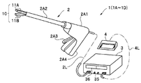
- the treatment system 1 of the present embodiment includes a treatment tool 2, a main body 3 that is a treatment tool control device, and a foot switch 4.
- the treatment instrument 2 is a surgical energy anastomosis apparatus that performs a joint treatment of living tissues in the abdominal cavity through, for example, the abdominal wall.
- the treatment instrument 2 includes a grip 2A1, a shaft 2A2, and a pair of openable and closable holding portions 11 (first holding portion 11A and second holding portion 11B) that hold a living tissue LT that is a treatment target and perform treatment. It has the treatment part 10 which becomes.
- each of the first clamping unit 11A and the second clamping unit 11B is referred to as a clamping unit 11.
- the grip 2A1 is connected to the main body 3 via a cable 2L.
- a grip 2A1 having an opening / closing knob 2A3 for operating the operator to open and close the treatment section 10 has a shape that is easy for an operator to grip, for example, a substantially L-shape.
- a grip 2A3 that is integrated with the treatment section 10 and transmits the operation of the opening / closing knob 2A3 to the treatment section 10 is disposed.
- the other end side of the grip 2A1 is a grasping portion 2A4 grasped by the operator.
- the main body 3 has a display unit 36 for displaying treatment conditions and the like, and a setting operation unit 35 for the operator to set treatment conditions and the like on the front panel, and the foot switch 4 is connected via a cable 4L. .
- the foot switch 4 is not an essential component and may be a switch or the like that is operated by a surgeon at hand.
- the treatment tool 2 applies thermal energy (TH energy) to the living tissue LT via the treatment surfaces 11SA and 11SB that are contact surfaces with the living tissue LT.
- TH energy thermal energy
- the treatment unit 10 can be opened and closed by, for example, the second clamping unit 11B moving relative to the first clamping unit 11A.
- the second clamping portion 11B As shown in FIG. 2A, when the opening / closing knob 2A3 is not pressed by the operator, the second clamping portion 11B is in the proximity or contact state with the first clamping portion 11A due to the biasing force of an elastic member (not shown).
- the opening / closing knob 2A3 when the operator presses the opening / closing knob 2A3 with a force stronger than the urging force of the elastic member, the second holding portion 11B is separated from the first holding portion 11A, and the treatment is performed. Part 10 is in the open state.
- the living tissue LT inserted between the first sandwiching section 11A and the second sandwiching section 11B is attached to the elastic member when the surgeon stops pressing the opening / closing knob 2A3.
- the force is held between the treatment surface 11SA of the first sandwiching portion 11A and the treatment surface 11SB of the second sandwiching portion 11B while being pressed.
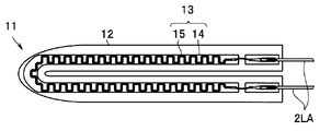
- the treatment surface 11S of the holding part 11 is the front surface (outer surface) of the heat transfer body 12 made of metal such as stainless steel or copper.
- the heat generating element 13 is joined to the back surface (inner surface) of the heat transfer body 12.
- the upper surface of the heating element 13 is covered and insulated by an insulator 16 such as polyimide.
- the heating element 13 has a heating resistor 15 formed on the surface of a substrate 14 such as alumina or aluminum nitride.
- the heating resistor 15 is made of platinum having a positive resistance temperature coefficient that increases the electrical resistance R as the temperature rises. For this reason, as will be described later, the temperature T1 of the heating element 13 (heating resistor 15) can be calculated from the electrical resistance R of the heating resistor 15.
- various positive resistance temperature coefficient refractory metal materials such as NiCr alloy, Ta, or W may be used.
- the heat generating element 13 is an output unit that applies heat generation power (TH) output from the main body 3 to the living tissue LT as heat energy.
- TH heat generation power
- the treatment instrument 2 has a temperature sensor 19 protruding from the treatment surface 11S.
- the temperature sensor 19 is housed inside when the space between the first sandwiching portion 11A and the second sandwiching portion 11B is closed, and protrudes by an urging force by an elastic body such as a spring when the space is opened.
- the temperature sensor 19 is inserted into the living tissue LT sandwiched between the first sandwiching portion 11A and the second sandwiching portion 11B and detects the temperature (tissue temperature) T2 of the living tissue LT.
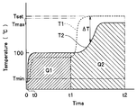
- tissue temperature T2 is lower than the temperature (element temperature) T1 of the heating element 13 by the temperature difference ⁇ T due to heat transfer.
- the tissue temperature T2 is, for example, the lowest temperature, that is, the temperature of the biological tissue in the middle between the treatment surface 11SA and the treatment surface 11SB.
- the tissue temperature T2 may be the surface temperature of the portion in contact with the treatment surface 11S instead of the internal temperature of the tissue as long as it is the temperature of the living tissue being treated.
- the heating element 13 is disposed in each of the sandwiching portions 11A and 11B, but the heating element 13 may be disposed in at least one of the sandwiching portions 11.
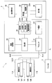
- the treatment system 1 includes the treatment tool 2, the main body 3, and the foot switch 4.
- the main body 3 includes a heat generating power (TH) power supply 30, a heat generating power sensor (TH sensor) 31, a setting unit 32, a calculating unit 33, a control unit 34, and a temperature measuring unit 39. .
- TH heat generating power
- TH sensor heat generating power sensor
- the power supply 30 outputs heat generation power (TH) for heat energy.
- TH heat generation power
- the TH sensor 31 as a detection unit detects the output value (voltage and current) of TH.
- the product of voltage and current is power P.
- the control unit 34 includes a comparison unit 34A, an instruction unit 34B, and a power supply control unit 34C, and controls the entire treatment system 1.
- the temperature measurement unit 39 measures the temperature (tissue temperature) T2 of the living tissue to which thermal energy is applied from the output of the temperature sensor 19.
- the calculating unit 33 calculates the electric resistance R of the heat generating element 13 from the voltage and current of the electric power TH, and calculates the temperature (element temperature) T1 of the heat generating element from the calculated electric resistance R. That is, the calculation unit 33 includes a storage unit (not shown) in which a calculation formula based on the resistance temperature coefficient of the heating element 13 or a correspondence table between the electrical resistance R and the element temperature T1 is stored. The calculation unit 33 may calculate the element temperature T1 directly from the TH voltage and current without calculating the electric resistance R.
- the calculation unit 33 also calculates a heating amount Q that is a time integral value of the living tissue temperature T2.
- the heating amount Q is a product of the temperature and the application time, and is expressed in units of “° C. seconds”, for example.
- the heating amount Q from the treatment start (time 0) to time t is calculated by the following (Formula 2).
- the heating amount Q can also be expressed as an integrated temperature in units of “° C.” obtained by adding the biological tissue temperature T2 every predetermined time, for example, every second. That is, the time integrated value and the integrated temperature are physical quantities indicating the same state although the units are different.
- the heating amount Q is a physical quantity that is completely different from the calorie in units of joules.
- the setting unit 32 sets treatment conditions based on the operation of the setting operation unit 35 and the like.
- the setting unit 32 includes a storage unit 32M.
- the storage unit 32M including a semiconductor memory or the like may store a plurality of different treatment conditions such as a heating amount setting value Qset described later.
- the setting operation unit 35 can be regarded as a part of the broad setting unit 32S.
- the CPU or the like constituting the control unit 34 may have at least some of the functions of the temperature measurement unit 39, the calculation unit 33, and the setting unit 32. Moreover, each may be an independent CPU. Further, the storage unit 32M of the setting unit may have the function of the storage unit of the calculation unit 33.
- the display unit 36 is a notification unit that notifies the surgeon of information such as the set treatment conditions, the output value of the power during the treatment, and the tissue temperature T2.
- the comparison unit 34A compares the time integral value (heating amount Q) of the temperature of the living tissue calculated by the calculation unit 33 with a predetermined setting value (heating amount setting value Qset).
- the instruction unit 34B issues an instruction based on the result of comparison performed by the comparison unit 34A.
- the power supply control unit 34C controls the power supply 30 based on an instruction from the instruction unit 34B so that application of treatment energy is reduced or terminated. Further, instead of the control by the power supply control unit 34C, display may be performed on the display unit 36 so as to end the processing based on an instruction from the instruction unit 34B, or sound may be generated from a speaker as a notification unit. Good. Of course, the power supply control unit 34C may control the power supply 30, and the notification unit may perform notification.
- the comparison unit 34 ⁇ / b> A compares the heating amount Q calculated by the calculation unit 33 with the heating amount setting value Qset that is a predetermined setting value set by the setting unit 32.
- the instruction unit 34B issues an instruction to the power supply control unit 34C. Based on the instruction, the power supply control unit 34C controls the TH power supply 30 so that the application of the treatment energy to the living tissue LT is reduced or terminated.
- a treatment condition including the following heating amount setting value Qset is set via the setting unit 32 including the setting operation unit 35.
- Element temperature set value Tset 220 ° C. Heating amount set value Qset: 800 ° C. Lower limit temperature Tmin: 50 ° C. Maximum temperature Tmax: 230 ° C
- the element temperature set value Tset is a target temperature of the heating element 13 to be controlled at a constant temperature.
- the element temperature setting value Tset may be a target temperature of the tissue temperature.
- the lower limit temperature Tmin is a temperature at which a change begins to occur in the living tissue. In other words, the living tissue is not substantially treated until the lower limit temperature Tmin is reached.
- the upper limit temperature Tmax is a temperature at which the biological tissue being treated may be damaged unexpectedly and may begin to adversely affect the surrounding site.
- the treatment time (treatment energy application time) is set as the treatment condition, whereas in the treatment system 1, the application of the thermal energy at the tissue temperature T2 is completed.
- a heating amount set value Qset that is a time integral value of is set.
- the treatment condition can be set by the operator according to the treatment from among a plurality of treatment conditions stored in the storage unit 32M, for example, but as will be described later, the setting unit 32 according to the type of the living tissue LT. May be set automatically.
- each condition may be set individually, or may be selected as a treatment condition set in which a plurality of conditions are set in advance.
- a plurality of treatment condition sets LV1 to LV3 may be stored in the storage unit 32M in advance according to the type of living tissue LT to be treated.
- the closed treatment unit 10 is inserted into the abdominal cavity through, for example, the abdominal wall.
- the second holding part 11B opens with respect to the first holding part 11A.
- the treatment target living tissue LT is disposed between the treatment surface 11SA of the first sandwiching portion 11A and the treatment surface 11SB of the second sandwiching portion 11B.
- the opening / closing knob 2A3 is opened, the second clamping part 11B is closed with respect to the first clamping part 11A by the biasing force of the elastic member, and as shown in FIG. Then, it is sandwiched in a pressed state between the treatment surface 11SA of the first sandwiching portion 11A and the treatment surface 11SB of the second sandwiching portion 11B.
- Step S13> The surgeon presses the foot switch 4 with his / her foot. Then, the control unit 34 performs control so that the power supply 30 outputs heat generation power (TH). The control unit 34 starts constant temperature control of the output value P of the power supply 30 so that the element temperature T1 becomes the element temperature set value Tset.
- the average temperature of the heating elements 13A and 13B or one temperature of the heating elements 13A and 13B is regarded as the element temperature T1, and one power source 30 is controlled. Each temperature may be calculated and controlled by each power source.
- the temperature measuring unit 39 measures the tissue temperature T2.
- Step S15 The control unit 34 determines whether the tissue temperature T2 has risen to the lower limit temperature Tmin or higher. If it becomes more than minimum temperature Tmin (YES), it will shift to Step S16. For this reason, the heating amount Q is not calculated during the period lower than the lower limit temperature Tmin (between time 0 and t0).
- Step S16> The control unit 34 determines whether the tissue temperature T2 has risen to the upper limit temperature Tmax or higher. When the temperature exceeds the upper limit temperature Tmax (YES), the process proceeds to step S19 and the treatment is stopped. At this time, it is preferable that the control unit 34 displays a warning on the display unit 36.
- control based on the lower limit temperature Tmin and the upper limit temperature Tmax is not essential control of the treatment stem 1 of the embodiment.
- the calculation unit 33 calculates a heating amount Q that is a time integral value of the tissue temperature T2. For example, ⁇ Q (tissue temperature T2 ⁇ 1 second) is added to the heating amount Q so far as the heating amount Q shown in (Expression 2).
- the comparison unit 34A of the control unit 34 compares the heating amount Q with the heating amount set value Qset, and when the heating amount Q becomes equal to or higher than the superheat amount setting value Qset (YES), an instruction signal is sent from the instruction unit 34B to the power supply 30.
- the power supply control unit 34C controls the power supply 30 and ends the output of TH. That is, based on the heating amount set value Qset and the heating amount Q, the output of TH ends.
- step S18 the comparing unit 34A compares the time integral value (heating amount Q) calculated by the calculating unit 33 with a predetermined set value (heating amount set value Qset), and the instruction unit 34B Step S18B which issues an instruction based on the comparison result of the comparison unit 34A, and step S18C in which the power supply control unit 34C controls the power supply 30 based on the instruction from the instruction unit 34B.
- the power supply control unit 34C may control the power supply 30 to reduce the TH output to a level at which the TH output does not substantially affect the living tissue.
- FIG. 8 shows the relationship between the heating amount Q and the bonding strength of the treated living tissue LT. From FIG. 8, it is clear that a good treatment result can be obtained by using the heating amount Q as a reference. That is, if the heating amount Q is equal to or greater than the predetermined heating amount QA, a practically sufficient bonding strength SA can be obtained.
- the storage unit 32M stores a heating amount setting value Qset determined based on an experimental value of the heating amount QA.
- a tissue temperature set value is set as a target temperature for constant temperature control instead of the element temperature set value Tset, and the control unit 34 sets the TH power output value P to a constant temperature so that the tissue temperature T2 becomes the tissue temperature set value. You may control.
- the main body 3 that is a treatment instrument control device includes a treatment instrument that applies treatment energy to a living tissue, a power source that outputs electric power for conversion to the treatment energy, and the temperature of the living tissue.
- a temperature measurement unit for measuring the temperature a calculation unit for calculating a time integral value of the temperature from the temperature measured by the temperature measurement unit and the application time of the treatment energy, and a time integration of the temperature calculated by the calculation unit
- a comparison unit that compares the value with a predetermined set value; and an instruction unit that issues an instruction based on a result of the comparison performed by the comparison unit.
- the operation method of the treatment system includes a step in which a power source outputs electric power, a treatment instrument converts the electric power into treatment energy and treats living tissue, and a temperature measurement unit applies the treatment energy. Comparing the measured temperature of the living tissue with the step of calculating the time integral value of the temperature of the living tissue from the measured temperature of the living tissue and the time when the treatment energy is applied.
- the unit operates the step of comparing the time integration value calculated by the calculation unit with a predetermined set value, and the instruction unit issues an instruction based on the result of the comparison by the comparison unit.
- the treatment system 1 can easily obtain a good treatment result because the application time of heat energy is controlled based on the heating amount Q. That is, the treatment system 1, the main body 3 that is the treatment instrument control device, and the operation method of the treatment system 1 have good operability.
- the temperature measuring unit 39 may estimate the tissue temperature T2 from the element temperature T1 and the output value P of power (TH). That is, the temperature measurement unit 39 may measure the tissue temperature T2 indirectly through the output value P or the like instead of directly measuring the tissue temperature T2 with a temperature sensor or the like.
- the output value P is controlled at a constant temperature so that the element temperature T1 becomes a predetermined element temperature set value Tset. For this reason, when the temperature difference ⁇ T is large, a larger TH of the output value P is required. That is, as shown in FIG. 9, the temperature difference ⁇ T has a strong correlation with the output value P of the heat generation power (TH). Note that the temperature difference ⁇ T in FIG. 9 is based on experimental values obtained by actually measuring the tissue temperature T2 with a temperature sensor similar to the temperature sensor 19.
- T2 can be calculated from (Equation 3) below.
- the temperature measuring unit 39 calculates the temperature T1 of the heating element 13 from the electrical resistance of the heating element 13, and further estimates the temperature T2 of the living tissue from the temperature T1 of the heating element 13 and the output value P of the power.
- the temperature sensor is unnecessary, and the calculation unit 33 may have the function of the temperature measurement unit 39.
- f (P) is acquired in advance by experiments and stored in a storage unit (not shown) as an expression or a table (table data).
- the straight line shown in FIG. 9 shows an example in which a plurality of experimental data (plots) are approximated by a linear equation by the least square method.
- the expression f (P) may be a quadratic expression or the like, or the electric power P may be divided into a plurality of ranges and may be composed of a plurality of different expressions for each section. In the case of storing in a table, for example, ⁇ T corresponding to every 5 W of power P is stored in the table.
- the ratio Q / Qset of the heating amount Q calculated by the calculating unit 33 to the heating amount set value Qset is displayed on the notification unit 36B of the display unit 36.
- the instruction unit 34B issues an instruction to the notification unit 36B based on the result of the comparison performed by the comparison unit 34A. Then, the state of treatment progress is displayed on the notification unit 36B like a bar graph. The surgeon can check the progress of the treatment by displaying the notification unit 36B.
- the notification to the surgeon by the notification unit is not limited to the notification unit 36B of the display unit 36 as long as the surgeon can recognize the sound (voice information, melody type, frequency change), or It may be a notification unit that notifies by vibration intensity or the like.
- the treatment systems 1A to 1C, the treatment instrument control device, and the operation method of the treatment system according to the first to third modifications of the first embodiment will be described.
- a treatment system or the like (the treatment system, the treatment instrument control device, and the operation method of the treatment system 1) is referred to as a treatment system or the like. Since the treatment systems 1A to 1C and the like are similar to the treatment system 1 and the like, components having the same functions are denoted by the same reference numerals and description thereof is omitted.
- the treatment energy applied was thermal energy.
- the treatment energy is one of thermal energy, ultrasonic energy, light energy, and high-frequency power energy, the same effect can be obtained.
- laser light which is light energy
- the power source outputs power to a light source that generates laser light.
- the living tissue to which the laser beam is applied generates heat.
- a specific treatment site can be selectively heated by selecting the wavelength of the laser beam.
- the temperature measurement unit 39 measures the tissue temperature T2 based on the detection result of the infrared thermometer.
- the treatment tool of the treatment system 1C has an ultrasonic vibrator inside the grip 2A1, and the sandwiching portion 11A is ultrasonically vibrated back and forth.
- the living tissue held between the holding portion 11A that vibrates and the holding portion 11B that does not vibrate generates heat due to frictional heat.
- the tissue temperature T2 is detected by, for example, a temperature sensor that detects the temperature of the treatment surface 11SB of the clamping unit 11B.
- the heat transfer body made of metal of the treatment tool of the treatment system 1C has a function as an electrode for applying high frequency power (HF) to the living tissue.
- HF high frequency power
- the energy application time is controlled based on the heating amount Q based on the temperature of the living tissue, as in the treatment system 1 and the like. Good sex.
- the treatment tool 2D of the treatment system 1D sequentially applies high-frequency power energy (HF energy) and thermal energy (TH energy) to the living tissue LT via the treatment surfaces 11SA and 11SB.
- HF energy high-frequency power energy
- TH energy thermal energy
- HF energy has an action of releasing intracellular components including high molecular compounds such as proteins by destroying cell membranes of living tissues and homogenizing them with extracellular components such as collagen. Moreover, HF energy also has the effect
- the heat transfer body made of metal of the treatment tool 2D of the treatment system 1D also has a function as the electrode 12.
- the main body 3D includes a high frequency power (HF) power source 30A as a first power source, a heating power (TH) power source 30B as a second power source, an HF sensor 31A, a TH sensor 31B, and a setting unit 32.
- the calculation unit 33 and the control unit 34 are provided.
- the tissue temperature T ⁇ b> 2 is estimated from the temperature T ⁇ b> 1 of the heating element 13 and the power output value P, and the calculation unit 33 has the function of the temperature measurement unit 39.
- control part 34 contains the comparison part 34A, the instruction
- the HF power source 30A outputs high frequency power (HF) that is first power.
- the TH power source 30B outputs heat power (TH) that is second power.
- HF high frequency power
- TH heat power
- the HF power supply 30A and the TH power supply 30B do not output power at the same time, and thus may be a single shared power supply. In this case, the HF sensor 31A and the TH sensor 31B may be shared.
- HF sensor 31A as the first detection unit detects the output value (voltage and current) of HF.
- the TH sensor 31B which is the second detection unit, detects the output value (voltage and current) of TH.
- a total heating amount QT that is an addition value of the high-frequency power energy heating amount (first heating amount) Q1 by applying HF energy and the thermal energy heating amount (second heating amount) Q2 by applying TH energy is set in advance.
- the control unit 34 controls the TH power supply 30B to end the TH energy application. That is,
- Step S21> For example, the following treatment conditions are set by the setting unit 32 including the setting operation unit 35.
- the element temperature set value Tset is set to be higher than 70 ° C., for example, higher than 100 ° C., higher than the tissue temperature at the end of HF application (100 ° C. ⁇ 30 ° C.).
- the lower limit temperature Tmin and the upper limit temperature Tmax are also set, and the control unit 34 performs control based on the lower limit temperature Tmin and the upper limit temperature Tmax.
- the control is the same as that of the treatment system 1, the description is omitted.
- the setting unit 32 may automatically set the heating amount setting value Qset according to the characteristics of the living tissue LT held between the pair of holding units 11.
- the heating amount set value Qset is automatically set based on at least one of the gap G between the pair of holding portions 11A and 11B where the living tissue LT is held and the initial impedance of HF.
- the interval G is information on the size of the living tissue LT that is the object to be treated.
- the initial impedance of HF is tissue information including the moisture content of the living tissue LT. Further, as the initial impedance of HF, a minimum impedance value, a time when the impedance is equal to or less than a predetermined value, or the like can be used.
- a treatment condition for a series of treatments is set by the setting unit 32.
- the setting unit 32 automatically sets the treatment conditions for the treatment B. It may be set.
- the surgical procedure is “lobe lobectomy”, (treatment A) pulmonary lobule artery sealing, (treatment B) pulmonary lobule vein sealing, (treatment C) pulmonary lobe bronchial sealing, (treatment D)
- a series of treatment conditions (treatment A) to (treatment D) are set only by the operator selecting an operation method. Is good.
- Step S22> The living tissue LT to be treated is sandwiched in a pressed state between the treatment surface 11SA of the first sandwiching portion 11A and the treatment surface 11SB of the second sandwiching portion 11B.
- Step S23> The operator presses the foot switch 4 with his / her foot while the living tissue LT is held between the treatment sections 10. Then, the control unit 34 starts treatment. That is, the control unit 34 first controls the HF power source 30A to output high frequency power (HF). HF is transmitted to the electrodes 12A and 12B of the treatment instrument 2 via the cable 2L. Then, high frequency power is applied to the living tissue LT sandwiched between the electrodes 12A and 12B, and the living tissue LT is heated by Joule heat.
- HF high frequency power
- the HF energy causes the living tissue itself in the HF energization path between the electrode 12A and the electrode 12B to generate heat. For this reason, in the HF energy application step, the tissue temperature T2 rises without causing temperature unevenness to the center even if the living tissue LT is thick. Although the treatment unit 10 does not generate heat, the element temperature T1 also rises due to heat transfer from the generated living tissue LT.
- the control unit 34 performs constant power control of the HF output value P1 with an HF output set value Pset, for example, 60 W, based on the HF current and voltage detected by the HF sensor 31A.
- the calculation unit 33 calculates a high-frequency power heating amount (first heating amount) Q1, which is a time integral value of the tissue temperature T2.
- the tissue temperature T2 may be measured by the temperature sensor 19 inserted into the living tissue LT or an infrared sensor.
- the tissue temperature T2 at the time of applying HF energy can be regarded as constant after the initial rapid increase because the living tissue LT contains water. That is, even when energy is applied, the temperature of the living tissue LT including water is maintained at a temperature near the boiling point (100 ° C.), which is a constant temperature at atmospheric pressure, for example, 100 ° C. ⁇ 30 ° C.
- the first heating amount Q1 up to the time t after the start of treatment may be calculated by the following (formula 5) without using a sensor or the like.
- step S24 of the first heating amount Q1 by the calculation unit 33 may be performed using the following (formula 6) after step S26 described later.
- Step S25> In the treatment system 1D, when HF energy application is started, the impedance Z is calculated by the calculation unit 33 from the voltage and current of the HF detected by the HF sensor 31A.
- Impedance Z increases due to dehydration accompanying the degeneration of the living tissue LT as the treatment progresses.
- the control unit 34 performs the processing from S23 until the impedance Z is set to be equal to or higher than the HF end impedance Zset (No).
- the output of the HF is completed based on the impedance Z of the HF.
- Step S27> The control unit 34 starts control to apply TH energy to the living tissue LT instead of HF energy.
- the control unit 34 controls the output value P2 of the TH power supply 30B at a constant temperature based on the element temperature T1 of the treatment unit 10.
- the heat generating element 13 is controlled to have the element temperature set value Tset set in S21.
- TH may be direct current or high frequency, and the frequency in the case of high frequency may be the same as HF.
- the high frequency power (HF) applied from the electrode 12 to the living tissue LT heats the living tissue LT as Joule heat, whereas the heating power (TH) directly transfers heat energy to the living tissue LT.
- the heat (TH) energy transferred to the living tissue LT via the treatment surface 11S is set to 100 ° C. according to the element temperature setting value Tset regardless of the denatured state of the living tissue LT, for example, the water content. It can be heated to a super temperature.
- the calculation unit 33 calculates a second heating amount (thermal energy heating amount) Q2, which is a time integral value of the tissue temperature T2. That is, in S28, the second heating amount Q2, which is a time integral value of the tissue temperature T2, is calculated while controlling the constant temperature based on the element temperature T1 calculated from the electric resistance R and applying thermal energy to the living tissue LT. . Further, the calculation unit 33 calculates a total heating amount QT obtained by adding the first heating amount Q1 and the second heating amount Q2.
- step S29 as with step S18 shown in FIG. 7, the time integration value (total heating amount QT) calculated by the calculating unit 33 and the predetermined set value (heating amount setting value Qset) are compared by the comparison unit 34A.
- Step S29A in which the instruction unit 34B issues an instruction based on the comparison result of the comparison unit 34A
- step S29C in which the power supply control unit 34C controls the power supply 30 based on the instruction from the instruction unit 34B.
- step S29A in which the instruction unit 34B issues an instruction based on the comparison result of the comparison unit 34A
- step S29C in which the power supply control unit 34C controls the power supply 30 based on the instruction from the instruction unit 34B.
- the control unit 34 determines that the heating residual amount ⁇ Q shown in the following (Equation 7) becomes TH. The output may be terminated.
- Heating remaining amount ⁇ Q heating amount setting value Qset ⁇ first heating amount Q1 ⁇ second heating amount Q2 (Expression 7)
- control unit 34 may calculate the total heating amount QT or the remaining heating amount ⁇ Q. Further, the first heating amount Q1 may not be calculated, and only the control by the second heating amount Q2 may be performed. That is, only the reduction or termination of the heat energy may be performed based on the heating amount Q.
- the treatment system 1D can easily obtain a good treatment result because the energy application time, that is, the end of energy application is controlled using the heating amount Q of the living tissue temperature T2. For this reason, the operation method of treatment system 1D, main-body part 3D which is a treatment tool control apparatus, and treatment system 1D has good operativity.
- the first energy applied first is high-frequency power energy and the second energy applied next is thermal energy has been described.
- the first energy is any one of high-frequency power energy, thermal energy, light energy, and ultrasonic energy
- the second energy is any energy different from the first energy
- the treatment tool sequentially applies two or more treatment energy selected from thermal energy, ultrasonic energy, light energy, and high-frequency power energy to the living tissue, and the control unit applies at least one of the treatment energy.
- the treatment system that reduces or terminates the output based on the heating amount has the same effect as the treatment system 1D.
- a treatment system that stops a blood vessel by applying ultrasonic energy after the blood vessel has been stopped by application of HF energy has the same effect by performing the same control as the treatment system 1D.
- bipolar treatment instrument in which the living tissue LT is grasped by the pair of sandwiching portions 11 has been described.
- a monopolar treatment instrument may be a treatment system that is similarly controlled based on the total heating amount QT. Results are easily obtained.
Landscapes
- Health & Medical Sciences (AREA)
- Surgery (AREA)
- Engineering & Computer Science (AREA)
- Life Sciences & Earth Sciences (AREA)
- Medical Informatics (AREA)
- Molecular Biology (AREA)
- Nuclear Medicine, Radiotherapy & Molecular Imaging (AREA)
- Plasma & Fusion (AREA)
- Biomedical Technology (AREA)
- Heart & Thoracic Surgery (AREA)
- Physics & Mathematics (AREA)
- Otolaryngology (AREA)
- Animal Behavior & Ethology (AREA)
- General Health & Medical Sciences (AREA)
- Public Health (AREA)
- Veterinary Medicine (AREA)
- Surgical Instruments (AREA)
- Radiation-Therapy Devices (AREA)
- Thermotherapy And Cooling Therapy Devices (AREA)
- Laser Surgery Devices (AREA)
Abstract
Description
<処置システムの構成>
図1に示すように、本実施形態の処置システム1は、処置具2と、処置具制御装置である本体部3と、フットスイッチ4と、を具備する。処置具2は、例えば腹壁を通して腹腔内の生体組織の接合処置等を行う外科手術用エネルギ吻合装置である。
次に、図7のフローチャートに沿って、処置システム1の作動方法について説明する。
例えば、以下のような加熱量設定値Qsetを含む処置条件が、設定操作部35を含む設定部32を介して設定される。
加熱量設定値Qset:800℃秒
下限温度Tmin:50℃
上限温度Tmax:230℃
素子温度設定値Tset:180℃
加熱量設定値Qset:1000℃秒
下限温度Tmin:50℃
上限温度Tmax:190℃
素子温度設定値Tset:190℃
加熱量設定値Qset:2500℃秒
下限温度Tmin:50℃
上限温度Tmax:200℃
素子温度設定値Tset:200℃
加熱量設定値Qset:3500℃秒
下限温度Tmin:50℃
上限温度Tmax:210℃
図2Aに示したように、閉状態の処置部10が、例えば、腹壁を通して腹腔内に挿入される。術者がグリップ2A1の開閉ノブ2A3を握りしめる押圧操作をすると、第1挟持部11Aに対して第2挟持部11Bが開く。そして、処置対象の生体組織LTが、第1挟持部11Aの処置面11SAと第2挟持部11Bの処置面11SBとの間に配置される。この状態で、開閉ノブ2A3が開放されると、弾性部材の付勢力により、第1挟持部11Aに対して第2挟持部11Bが閉じ、図2Bに示すように、処置対象の生体組織LTは、第1挟持部11Aの処置面11SAと第2挟持部11Bの処置面11SBとの間に押圧状態で挟持される。
術者がフットスイッチ4を足で押圧操作する。すると、制御部34は、電源30が発熱用電力(TH)を出力するように制御する。制御部34は、素子温度T1が素子温度設定値Tsetになるように、電源30の出力値Pの定温制御を開始する。
温度測定部39が、組織温度T2を測定する。
制御部34は、組織温度T2が下限温度Tmin以上まで上昇したか判断する。下限温度Tmin以上になったら(YES)、ステップS16に移行する。
このため、下限温度Tmin未満の間(時間0からt0までの間)は、加熱量Qは算出されない。
制御部34は、組織温度T2が上限温度Tmax以上まで上昇したか判断する。上限温度Tmax以上になったら(YES)、ステップS19に移行し処置を中止する。このとき、制御部34が、表示部36に警告を表示することが好ましい。
算出部33は、組織温度T2の時間積分値である加熱量Qを算出する。
(式2)で示される加熱量Qは、例えば1秒毎に、ΔQ(組織温度T2×1秒)が、それまでの加熱量Qに加算される。
制御部34の比較部34Aは、加熱量Qと加熱量設定値Qsetとを比較し、加熱量Qが過熱量設定値Qset以上になる(YES)と、指示部34Bから指示信号が電源30に対して出力され、電源制御部34Cが電源30を制御し、THの出力を終了する。すなわち、加熱量設定値Qsetと加熱量Qとにもとづき、THの出力が終了する。
次に、第1実施形態の変形例1~3の処置システム1A~1C、処置具制御装置、および、処置システムの作動方法について説明する。なお、以下、(処置システム、処置具制御装置、および、処置システム1の作動方法)を、処置システム等という。処置システム1A~1C等は、処置システム1等と類似しているので、同じ機能の構成要素には同じ符号を付し説明は省略する。
変形例1の処置システム1A等では、生体組織に処置エネルギとして光エネルギであるレーザ光が印加される。すなわち、電源はレーザ光を発生する光源に電力を出力する。
変形例2の処置システム1B等では、生体組織に処置エネルギとして超音波エネルギが印加される。すなわち、電源は超音波振動子に電力を出力する。
変形例3の処置システム1C等では、生体組織に処置エネルギとして高周波電力エネルギが印加される。すなわち、電源は高周波電力を出力する。
次に、第2実施形態の処置システム1D等について説明する。処置システム1D等は、処置システム1等と類似しているので、同じ機能の構成要素には同じ符号を付し説明は省略する。
図12に示すように、処置システム1Dでは、HFエネルギの印加終了後に、THエネルギの印加が開始される(時間t=t1)。そして、制御部34は、加熱量Qで定義される組織温度T2の時間積分値にもとづき、処置終了(時間t=t2)を制御する。

例えば、以下のような処置条件が、設定操作部35を含む設定部32により設定される。
HF終了インピーダンスZset:120Ω
素子温度設定値Tset:180℃
加熱量設定値Qset:1000℃秒
処置対象の生体組織LTは、第1挟持部11Aの処置面11SAと第2挟持部11Bの処置面11SBとの間に押圧状態で挟持される。
処置部10に生体組織LTを挟持した状態で、術者がフットスイッチ4を足で押圧操作する。すると、制御部34は処置を開始する。すなわち、制御部34は、まず、HF電源30Aが高周波電力(HF)を出力するように制御する。HFは、ケーブル2Lを介して処置具2の電極12A、12Bに伝達される。すると、電極12A、12Bに挟持されている生体組織LTに高周波電力が印加され、生体組織LTはジュール熱により加熱される。
算出部33は、組織温度T2の時間積分値である高周波電力加熱量(第1加熱量)Q1を算出する。
ただし、t1;HFエネルギ印加時間
処置システム1Dでは、HFエネルギ印加を開始すると、HFセンサ31Aが検出するHFの電圧および電流からインピーダンスZが算出部33により算出される。
制御部34は、インピーダンスZが設定された、HF終了インピーダンスZset以上になったら、(YES)、S26において、HF電源30Aを制御しHFの出力を終了する(t=t1)。
制御部34は、HFエネルギにかえてTHエネルギを生体組織LTに印加する制御を開始する。
算出部33は、組織温度T2の時間積分値である第2加熱量(熱エネルギ加熱量)Q2を算出する。すなわち、S28では、THを電気抵抗Rから算出した素子温度T1にもとづき定温制御し生体組織LTに熱エネルギを印加しながら、組織温度T2の時間積分値である第2加熱量Q2が算出される。さらに、算出部33は、第1加熱量Q1と第2加熱量Q2とを加算した合計加熱量QTを算出する。
制御部34は、合計加熱量QTが、加熱量設定値Qset以上になる(YES)と、TH電源30Bを制御し、THの出力を終了する(t=t2)。すなわち、加熱量設定値Qsetと合計加熱量QTとにもとづき、THの出力が終了する。
2・・・処置具
3・・・本体部
10・・・処置部
12・・・伝熱体(電極)
13・・・発熱素子
19・・・温度センサ
30・・・電源
32・・・設定部
33・・・算出部
34・・・制御部
34A・・・比較部
34B・・・指示部
34C・・・電源制御部
35・・・設定操作部
36・・・表示部
39・・・温度測定部
Claims (27)
- 生体組織に処置エネルギを印加する処置具と、
前記処置エネルギに変換するための電力を出力する電源と、
前記処置エネルギが印加された前記生体組織の温度を測定するための温度測定部と、
前記温度測定部が測定する前記生体組織の温度と前記処置エネルギの印加時間とから、前記生体組織の温度の時間積分値を算出する算出部と、
前記算出部が、前記算出部が算出する前記生体組織の温度の前記時間積分値と所定の設定値とを比較する比較部と、
前記比較部が比較した結果に基づき指示を出す指示部と、
を有することを特徴とする処置システム。 - さらに、前記指示部からの指示に基づき、前記処置エネルギの印加が減少または終了するように前記電源を制御する電源制御部を有することを特徴とする請求項1に記載の処置システム。
- さらに、前記指示部からの指示に基づき、告知を行う告知部を有することを特徴とする請求項1に記載の処置システム。
- さらに、前記生体組織の温度の前記時間積分値の目標となる前記所定の設定値を設定する設定部を有することを特徴とする請求項1に記載の処置システム。
- 前記設定部は複数の異なる所定の設定値を記憶する記憶部を有することを特徴とする請求項4に記載の処置システム。
- さらに、前記設定部は複数の異なる所定の設定値に対応した処置条件を記憶し、
前記指示部からの指示に基づき、選択された前記処置条件に基づき前記処置エネルギの印加が減少または終了するように前記電源を制御する電源制御部を有することを特徴とする請求項4に記載の処置システム。 - 前記処置エネルギが、熱エネルギ、超音波エネルギ、光エネルギ、および、高周波電力エネルギの少なくともいずれかであることを特徴とする請求項1に記載の処置システム。
- 前記処置具は前記電力を熱エネルギに変換する発熱素子を有することを特徴とする請求項1に記載の処置システム。
- 前記温度測定部は前記発熱素子の出力から前記生体組織の温度を算出することを特徴とする請求項8に記載の処置
- 前記温度測定部が温度センサの出力から前記生体組織の温度を測定することを特徴とする請求項1に記載の処置システム。
- 前記生体組織の温度が所定の下限温度以上になってから、前記算出部が前記生体組織の温度の前記時間積分値の算出を開始することを特徴とする請求項1に記載の処置システム。
- 前記比較部は前記所定の設定値と前記生体組織の温度の前記時間積分値との比率を算出し、
前記告知部は前記比率を告知することを特徴とする請求項3に記載の処置システム。 - 前記処置具が前記生体組織に、熱エネルギ、超音波エネルギ、光エネルギ、および、高周波電力エネルギから選択される2以上の前記処置エネルギを順に印加し、
前記電源制御部が、少なくともいずれかの前記処置エネルギの出力の減少または終了を前記指示部の指示に基づいて行うことを特徴とする請求項2に記載の処置システム。 - 生体組織に処置エネルギを印加する処置具と、
前記処置エネルギに変換するための電力を出力する電源と、
前記処置エネルギが印加された前記生体組織の温度を測定するための温度測定部と、
前記温度測定部が測定する前記生体組織の温度と前記処置エネルギの印加時間とから、前記生体組織の温度の時間積分値を算出する算出部と、
前記算出部が算出する温度の時間積分値と所定の設定値とを比較する比較部と、
前記比較部が比較した結果に基づき指示を出す指示部と、
を有することを特徴とする処置具制御装置。 - 電源が、電力を出力するステップと、
処置具が、前記電力を処置エネルギに変換して生体組織に印加するステップと、
温度測定部が、前記処置エネルギが印加された前記生体組織の温度を測定するステップと、
算出部が、前記温度測定部により測定された前記生体組織の温度と前記処置エネルギの印加時間とから前記生体組織の温度の時間積分値を算出するステップと、
比較部が、前記算出部により算出された前記時間積分値と所定の設定値とを比較するステップと、
指示部が、前記比較部が比較した結果に基づき指示を出すステップと、
を動作することを特徴とする処置システムの作動方法。 - さらに、電源制御部が、前記指示に基づき、前記処置エネルギの印加が減少または終了するように前記電源を制御するステップと、
を動作することを特徴とする請求項15に記載の処置システムの作動方法。 - さらに、告知部が、前記指示に基づき、告知を行うステップを動作することを特徴とする請求項15に記載の処置システムの作動方法。
- さらに、設定部が、前記生体組織の温度の前記時間積分値の目標となる所定の設定値を設定するステップを動作することを特徴とする請求項15に記載の処置システムの作動方法。
- さらに、記憶部が、複数の異なる所定の設定値を記憶するステップを動作することを特徴とする請求項18に記載の処置システムの作動方法。
- さらに、前記設定部が、複数の異なる所定の設定値に対応した処置条件を記憶するステップと、
電源制御部が、前記指示部からの指示に基づき選択された前記処置条件に基づき前記処置エネルギの印加が減少または終了するように前記電源を制御するステップと、
を動作することを特徴とする請求項18に記載の処置システムの作動方法。 - 前記処置具が前記電力を前記処置エネルギに変換して生体組織を処置するステップでは、前記電力が熱エネルギ、超音波エネルギ、光エネルギ、および高周波電力エネルギの少なくともいずれかに変換されて処置が行われることを特徴とする請求項15に記載の処置システムの作動方法。
- 前記処置具が前記電力を処置エネルギに変換して前記生体組織を処置するステップでは、発熱素子が電力を熱エネルギに変換することを特徴とする請求項15に記載の処置システムの作動方法。
- 前記温度測定部が温度を測定するステップでは、前記発熱素子の出力から前記生体組織の温度を算出することを特徴とする請求項22に記載の処置システムの作動方法。
- 前記温度測定部が温度を測定するステップでは、温度センサの出力から前記生体組織の温度を測定することを特徴とする請求項15に記載の処置システムの作動方法。
- 前記算出部が前記時間積分値を算出するステップでは、前記生体組織の温度が所定の下限以下になってから、前記生体組織の温度の前記時間積分値の算出を開始することを特徴とする請求項15に記載の処置システムの作動方法。
- 前記比較部が比較するステップでは、前記所定の設定値と前記生体組織の温度の前記時間積分値との比率を算出し、前記告知部が告知を行うステップでは算出された比率を告知することを特徴とする請求項17に記載の処置システムの作動方法。
- 前記処置具が処置するステップでは、前記生体組織に対して熱エネルギ、超音波エネルギ、光エネルギおよび高周波電力エネルギから選択される2つ以上の処置エネルギを順に印加し、
前記電源制御部が前記電源を制御するステップでは、少なくともいずれかの前記処置エネルギの出力の減少または終了が前記指示部の指示に基づいて行われることを特徴とする請求項16に記載の処置システムの作動方法。
Priority Applications (4)
| Application Number | Priority Date | Filing Date | Title |
|---|---|---|---|
| CN201480043852.7A CN105451677B (zh) | 2013-08-02 | 2014-08-01 | 生物体组织接合系统 |
| JP2015516315A JP5847358B2 (ja) | 2013-08-02 | 2014-08-01 | 生体組織接合システム、および、生体組織接合システムの作動方法 |
| EP14833046.7A EP3011924A4 (en) | 2013-08-02 | 2014-08-01 | Treatment system, instrument control device, and treatment operation method |
| US15/012,537 US10245097B2 (en) | 2013-08-02 | 2016-02-01 | Living tissue bonding system and method for operating living tissue bonding system |
Applications Claiming Priority (2)
| Application Number | Priority Date | Filing Date | Title |
|---|---|---|---|
| US201361861654P | 2013-08-02 | 2013-08-02 | |
| US61/861,654 | 2013-08-02 |
Related Child Applications (1)
| Application Number | Title | Priority Date | Filing Date |
|---|---|---|---|
| US15/012,537 Continuation US10245097B2 (en) | 2013-08-02 | 2016-02-01 | Living tissue bonding system and method for operating living tissue bonding system |
Publications (1)
| Publication Number | Publication Date |
|---|---|
| WO2015016346A1 true WO2015016346A1 (ja) | 2015-02-05 |
Family
ID=52431869
Family Applications (1)
| Application Number | Title | Priority Date | Filing Date |
|---|---|---|---|
| PCT/JP2014/070348 Ceased WO2015016346A1 (ja) | 2013-08-02 | 2014-08-01 | 処置システム、処置具制御装置、および、処置システムの作動方法 |
Country Status (5)
| Country | Link |
|---|---|
| US (1) | US10245097B2 (ja) |
| EP (1) | EP3011924A4 (ja) |
| JP (2) | JP5847358B2 (ja) |
| CN (1) | CN105451677B (ja) |
| WO (1) | WO2015016346A1 (ja) |
Cited By (3)
| Publication number | Priority date | Publication date | Assignee | Title |
|---|---|---|---|---|
| WO2017130384A1 (ja) * | 2016-01-29 | 2017-08-03 | オリンパス株式会社 | 処置具及び処置システム |
| JPWO2016135977A1 (ja) * | 2015-02-27 | 2017-12-21 | オリンパス株式会社 | 医療用処置装置、医療用処置装置の作動方法、及び治療方法 |
| JP2018519919A (ja) * | 2015-06-30 | 2018-07-26 | エシコン エルエルシーEthicon LLC | 組織のパラメータに基づく同時エネルギーモダリティを使用するユーザーが適合可能な技法を有する外科用システム |
Families Citing this family (19)
| Publication number | Priority date | Publication date | Assignee | Title |
|---|---|---|---|---|
| US11090104B2 (en) | 2009-10-09 | 2021-08-17 | Cilag Gmbh International | Surgical generator for ultrasonic and electrosurgical devices |
| US9095367B2 (en) | 2012-10-22 | 2015-08-04 | Ethicon Endo-Surgery, Inc. | Flexible harmonic waveguides/blades for surgical instruments |
| US11129670B2 (en) | 2016-01-15 | 2021-09-28 | Cilag Gmbh International | Modular battery powered handheld surgical instrument with selective application of energy based on button displacement, intensity, or local tissue characterization |
| US10842523B2 (en) | 2016-01-15 | 2020-11-24 | Ethicon Llc | Modular battery powered handheld surgical instrument and methods therefor |
| DE112016006968T5 (de) * | 2016-07-05 | 2019-03-21 | Olympus Corporation | Medizinische Behandlungsvorrichtung, Betriebsverfahren einer medizinischen Behandlungsvorrichtung und Behandlungsverfahren |
| US11266430B2 (en) | 2016-11-29 | 2022-03-08 | Cilag Gmbh International | End effector control and calibration |
| WO2018167877A1 (ja) | 2017-03-15 | 2018-09-20 | オリンパス株式会社 | エネルギー源装置 |
| DE102019121375A1 (de) | 2019-08-07 | 2021-02-25 | Aesculap Ag | Vorrichtung und Verfahren zur Bestimmung eines Abschaltzeitpunktes eines medizinischen Instruments |
| US12262937B2 (en) | 2019-12-30 | 2025-04-01 | Cilag Gmbh International | User interface for surgical instrument with combination energy modality end-effector |
| US12336747B2 (en) | 2019-12-30 | 2025-06-24 | Cilag Gmbh International | Method of operating a combination ultrasonic / bipolar RF surgical device with a combination energy modality end-effector |
| US12076006B2 (en) | 2019-12-30 | 2024-09-03 | Cilag Gmbh International | Surgical instrument comprising an orientation detection system |
| US12053224B2 (en) | 2019-12-30 | 2024-08-06 | Cilag Gmbh International | Variation in electrode parameters and deflectable electrode to modify energy density and tissue interaction |
| US12023086B2 (en) | 2019-12-30 | 2024-07-02 | Cilag Gmbh International | Electrosurgical instrument for delivering blended energy modalities to tissue |
| US11759251B2 (en) | 2019-12-30 | 2023-09-19 | Cilag Gmbh International | Control program adaptation based on device status and user input |
| US11950797B2 (en) | 2019-12-30 | 2024-04-09 | Cilag Gmbh International | Deflectable electrode with higher distal bias relative to proximal bias |
| US11723716B2 (en) | 2019-12-30 | 2023-08-15 | Cilag Gmbh International | Electrosurgical instrument with variable control mechanisms |
| US12343063B2 (en) | 2019-12-30 | 2025-07-01 | Cilag Gmbh International | Multi-layer clamp arm pad for enhanced versatility and performance of a surgical device |
| US11949442B2 (en) | 2021-06-09 | 2024-04-02 | Siyata Mobile Inc. | Mobile conversion apparatus for docking cellular data devices |
| US20230051310A1 (en) * | 2021-08-16 | 2023-02-16 | Biosense Webster (Israel) Ltd. | Phrenic nerve warning |
Citations (8)
| Publication number | Priority date | Publication date | Assignee | Title |
|---|---|---|---|---|
| JP2001514541A (ja) * | 1997-03-05 | 2001-09-11 | ザ トラスティーズ オブ コロンビア ユニバーシティー イン ザ シティー オブ ニューヨーク | 組織をシールおよび結合または切断するための電熱デバイス |
| US20050222556A1 (en) | 2004-03-31 | 2005-10-06 | Terumo Kabushiki Kaisha | Apparatus and method for hyperthermia treatment |
| US20090076506A1 (en) | 2007-09-18 | 2009-03-19 | Surgrx, Inc. | Electrosurgical instrument and method |
| US20090248002A1 (en) | 2008-04-01 | 2009-10-01 | Tomoyuki Takashino | Treatment system, and treatment method for living tissue using energy |
| WO2012071388A2 (en) * | 2010-11-27 | 2012-05-31 | Securus Medical Group, Inc. | Ablation and temperature measurement devices |
| US20130019060A1 (en) | 2011-07-14 | 2013-01-17 | Advanced Micro Devices, Inc. | Creating multiple versions for interior pointers and alignment of an array |
| WO2013088892A1 (ja) * | 2011-12-12 | 2013-06-20 | オリンパスメディカルシステムズ株式会社 | 処置システム及び処置システムの制御方法 |
| WO2013094326A1 (ja) * | 2011-12-22 | 2013-06-27 | 学校法人慶應義塾 | バルーンカテーテル装置及びバルーンカテーテルの加熱方法 |
Family Cites Families (8)
| Publication number | Priority date | Publication date | Assignee | Title |
|---|---|---|---|---|
| US5553622A (en) * | 1991-01-29 | 1996-09-10 | Mckown; Russell C. | System and method for controlling the temperature of a catheter-mounted heater |
| US6626901B1 (en) | 1997-03-05 | 2003-09-30 | The Trustees Of Columbia University In The City Of New York | Electrothermal instrument for sealing and joining or cutting tissue |
| US7083613B2 (en) | 1997-03-05 | 2006-08-01 | The Trustees Of Columbia University In The City Of New York | Ringed forceps |
| US7008417B2 (en) * | 2002-04-22 | 2006-03-07 | Medtronics, Inc. | Detecting coagulum formation |
| JP4624697B2 (ja) * | 2004-03-12 | 2011-02-02 | オリンパス株式会社 | 手術用処置具 |
| US8216223B2 (en) * | 2006-01-24 | 2012-07-10 | Covidien Ag | System and method for tissue sealing |
| US8685016B2 (en) * | 2006-01-24 | 2014-04-01 | Covidien Ag | System and method for tissue sealing |
| US10682520B2 (en) * | 2012-01-27 | 2020-06-16 | Medtronic, Inc. | Managing recharge power for implantable medical devices |
-
2014
- 2014-08-01 JP JP2015516315A patent/JP5847358B2/ja active Active
- 2014-08-01 CN CN201480043852.7A patent/CN105451677B/zh active Active
- 2014-08-01 EP EP14833046.7A patent/EP3011924A4/en not_active Withdrawn
- 2014-08-01 WO PCT/JP2014/070348 patent/WO2015016346A1/ja not_active Ceased
-
2015
- 2015-11-24 JP JP2015228770A patent/JP6537110B2/ja active Active
-
2016
- 2016-02-01 US US15/012,537 patent/US10245097B2/en active Active
Patent Citations (8)
| Publication number | Priority date | Publication date | Assignee | Title |
|---|---|---|---|---|
| JP2001514541A (ja) * | 1997-03-05 | 2001-09-11 | ザ トラスティーズ オブ コロンビア ユニバーシティー イン ザ シティー オブ ニューヨーク | 組織をシールおよび結合または切断するための電熱デバイス |
| US20050222556A1 (en) | 2004-03-31 | 2005-10-06 | Terumo Kabushiki Kaisha | Apparatus and method for hyperthermia treatment |
| US20090076506A1 (en) | 2007-09-18 | 2009-03-19 | Surgrx, Inc. | Electrosurgical instrument and method |
| US20090248002A1 (en) | 2008-04-01 | 2009-10-01 | Tomoyuki Takashino | Treatment system, and treatment method for living tissue using energy |
| WO2012071388A2 (en) * | 2010-11-27 | 2012-05-31 | Securus Medical Group, Inc. | Ablation and temperature measurement devices |
| US20130019060A1 (en) | 2011-07-14 | 2013-01-17 | Advanced Micro Devices, Inc. | Creating multiple versions for interior pointers and alignment of an array |
| WO2013088892A1 (ja) * | 2011-12-12 | 2013-06-20 | オリンパスメディカルシステムズ株式会社 | 処置システム及び処置システムの制御方法 |
| WO2013094326A1 (ja) * | 2011-12-22 | 2013-06-27 | 学校法人慶應義塾 | バルーンカテーテル装置及びバルーンカテーテルの加熱方法 |
Non-Patent Citations (1)
| Title |
|---|
| See also references of EP3011924A4 * |
Cited By (6)
| Publication number | Priority date | Publication date | Assignee | Title |
|---|---|---|---|---|
| JPWO2016135977A1 (ja) * | 2015-02-27 | 2017-12-21 | オリンパス株式会社 | 医療用処置装置、医療用処置装置の作動方法、及び治療方法 |
| JP2018519919A (ja) * | 2015-06-30 | 2018-07-26 | エシコン エルエルシーEthicon LLC | 組織のパラメータに基づく同時エネルギーモダリティを使用するユーザーが適合可能な技法を有する外科用システム |
| JP2021065727A (ja) * | 2015-06-30 | 2021-04-30 | エシコン エルエルシーEthicon LLC | 組織のパラメータに基づく同時エネルギーモダリティを使用するユーザーが適合可能な技法を有する外科用システム |
| JP2023054129A (ja) * | 2015-06-30 | 2023-04-13 | エシコン エルエルシー | 組織のパラメータに基づく同時エネルギーモダリティを使用するユーザーが適合可能な技法を有する外科用システム |
| WO2017130384A1 (ja) * | 2016-01-29 | 2017-08-03 | オリンパス株式会社 | 処置具及び処置システム |
| JPWO2017130384A1 (ja) * | 2016-01-29 | 2018-12-13 | オリンパス株式会社 | 処置具及び処置システム |
Also Published As
| Publication number | Publication date |
|---|---|
| JP6537110B2 (ja) | 2019-07-03 |
| EP3011924A1 (en) | 2016-04-27 |
| JP2016041317A (ja) | 2016-03-31 |
| US10245097B2 (en) | 2019-04-02 |
| JPWO2015016346A1 (ja) | 2017-03-02 |
| JP5847358B2 (ja) | 2016-01-20 |
| CN105451677A (zh) | 2016-03-30 |
| CN105451677B (zh) | 2018-02-13 |
| EP3011924A4 (en) | 2017-03-22 |
| US20160143684A1 (en) | 2016-05-26 |
Similar Documents
| Publication | Publication Date | Title |
|---|---|---|
| JP5847358B2 (ja) | 生体組織接合システム、および、生体組織接合システムの作動方法 | |
| JP5816774B2 (ja) | 生体組織接合システム、処置具制御装置、および生体組織接合システムの作動方法 | |
| CN107405167B (zh) | 医疗用处置装置和医疗用处置装置的工作方法 | |
| JP4567811B2 (ja) | 電気手術装置、電気手術装置の制御方法、高周波処置装置、及び、高周波処置方法 | |
| JP2011530330A (ja) | 階段状の出力で切断及び凝固するための超音波装置 | |
| US10201366B2 (en) | Treatment method | |
| US10265549B2 (en) | Treatment method | |
| US10194932B2 (en) | Treatment method | |
| US20170086875A1 (en) | Treatment method | |
| CN108697453B (zh) | 能量手术器械 | |
| US11141215B2 (en) | Energy treatment instrument, treatment system, and controller | |
| US10034703B2 (en) | Control device for energy treatment tool, and energy treatment system | |
| JP2012161566A (ja) | 治療用処置装置及びその制御方法 | |
| JPWO2018008097A1 (ja) | 医療用処置装置、医療用処置装置の作動方法、及び治療方法 | |
| US20180185053A1 (en) | Surgical system | |
| US10314636B2 (en) | Treatment apparatus and method for controlling the same | |
| US12023085B2 (en) | Ultrasonic systems and methods with tissue resistance sensing | |
| US11399859B2 (en) | Energy control device and treatment system | |
| WO2017094193A1 (ja) | 熱エネルギ処置装置、及び熱エネルギ処置装置の作動方法 | |
| US20170319261A1 (en) | Medical treatment device | |
| US20170086916A1 (en) | Treatment method |
Legal Events
| Date | Code | Title | Description |
|---|---|---|---|
| WWE | Wipo information: entry into national phase |
Ref document number: 201480043852.7 Country of ref document: CN |
|
| 121 | Ep: the epo has been informed by wipo that ep was designated in this application |
Ref document number: 14833046 Country of ref document: EP Kind code of ref document: A1 |
|
| ENP | Entry into the national phase |
Ref document number: 2015516315 Country of ref document: JP Kind code of ref document: A |
|
| WWE | Wipo information: entry into national phase |
Ref document number: 2014833046 Country of ref document: EP |
|
| NENP | Non-entry into the national phase |
Ref country code: DE |