WO2015019554A1 - 基地局システム及び無線伝送装置 - Google Patents
基地局システム及び無線伝送装置 Download PDFInfo
- Publication number
- WO2015019554A1 WO2015019554A1 PCT/JP2014/003745 JP2014003745W WO2015019554A1 WO 2015019554 A1 WO2015019554 A1 WO 2015019554A1 JP 2014003745 W JP2014003745 W JP 2014003745W WO 2015019554 A1 WO2015019554 A1 WO 2015019554A1
- Authority
- WO
- WIPO (PCT)
- Prior art keywords
- base station
- wireless transmission
- communication
- storage battery
- wireless
- Prior art date
- Legal status (The legal status is an assumption and is not a legal conclusion. Google has not performed a legal analysis and makes no representation as to the accuracy of the status listed.)
- Ceased
Links
Images


Classifications
-
- H—ELECTRICITY
- H04—ELECTRIC COMMUNICATION TECHNIQUE
- H04L—TRANSMISSION OF DIGITAL INFORMATION, e.g. TELEGRAPHIC COMMUNICATION
- H04L12/00—Data switching networks
- H04L12/02—Details
- H04L12/10—Current supply arrangements
-
- H—ELECTRICITY
- H02—GENERATION; CONVERSION OR DISTRIBUTION OF ELECTRIC POWER
- H02J—ELECTRIC POWER NETWORKS; CIRCUIT ARRANGEMENTS OR SYSTEMS FOR SUPPLYING OR DISTRIBUTING ELECTRIC POWER; SYSTEMS FOR STORING ELECTRIC ENERGY
- H02J7/00—Circuit arrangements for charging or discharging batteries or for supplying loads from batteries
- H02J7/34—Parallel operation in networks using both storage and other DC sources, e.g. providing buffering
- H02J7/35—Parallel operation in networks using both storage and other DC sources, e.g. providing buffering with light sensitive cells
-
- H—ELECTRICITY
- H04—ELECTRIC COMMUNICATION TECHNIQUE
- H04W—WIRELESS COMMUNICATION NETWORKS
- H04W8/00—Network data management
- H04W8/22—Processing or transfer of terminal data, e.g. status or physical capabilities
- H04W8/24—Transfer of terminal data
- H04W8/245—Transfer of terminal data from a network towards a terminal
-
- H—ELECTRICITY
- H02—GENERATION; CONVERSION OR DISTRIBUTION OF ELECTRIC POWER
- H02J—ELECTRIC POWER NETWORKS; CIRCUIT ARRANGEMENTS OR SYSTEMS FOR SUPPLYING OR DISTRIBUTING ELECTRIC POWER; SYSTEMS FOR STORING ELECTRIC ENERGY
- H02J7/00—Circuit arrangements for charging or discharging batteries or for supplying loads from batteries
- H02J7/40—Circuit arrangements for charging or discharging batteries or for supplying loads from batteries characterised by the exchange of charge or discharge related data
- H02J7/42—Circuit arrangements for charging or discharging batteries or for supplying loads from batteries characterised by the exchange of charge or discharge related data with electronic devices having internal batteries, e.g. mobile phones
-
- H—ELECTRICITY
- H04—ELECTRIC COMMUNICATION TECHNIQUE
- H04W—WIRELESS COMMUNICATION NETWORKS
- H04W84/00—Network topologies
- H04W84/02—Hierarchically pre-organised networks, e.g. paging networks, cellular networks, WLAN [Wireless Local Area Network] or WLL [Wireless Local Loop]
- H04W84/10—Small scale networks; Flat hierarchical networks
- H04W84/12—WLAN [Wireless Local Area Networks]
Definitions
- the present application relates to a base station system including a base station apparatus and a wireless transmission apparatus for connecting the base station apparatus to a mobile backhaul network.
- a wireless transmission device is generally used when connecting a base station to a mobile backhaul network.
- the wireless transmission device is a point-to-point wireless communication device using, for example, a microwave or a millimeter wave, and communicates with a base station device and wirelessly with an opposite device.
- Wireless connection between a base station and a mobile backhaul network has advantages in terms of ease of network construction, high economic efficiency, and relaxation of restrictions on the location of the base station, compared to wired connection using optical fibers. .
- the mobile backhaul network means a line for connecting a base station of a cellular communication system to a core network, a line for connecting base stations, or both.
- the mobile backhaul network is an upper network to which a plurality of base stations are connected.
- the mobile backhaul network includes, for example, a control node that performs signaling between a base station and a mobile station, an exchange node that processes a voice call, a packet transfer node that performs user packet transfer, and the like.
- a mobile backhaul network is typically a network managed by a mobile operator (mobile operator).
- the mobile backhaul network includes, for example, a core network and, depending on the architecture, also includes a radio access network.
- the mobile backhaul network includes RNC (Radio Network Controller) and core network nodes (SGSN (Serving GPRS Support Node), GGSN (Gateway GPRS Support Node), MSC (Mobile Switching Center). ) Etc.).
- RNC Radio Network Controller
- SGSN Server GPRS Support Node
- GGSN Gateway GPRS Support Node
- MSC Mobile Switching Center
- Etc. Etc.
- the mobile backhaul network may include core network nodes (MME (Mobility Management Entity), S-GW (Serving Gateway), P-GW (PDN Gateway), etc.)).
- MME Mobility Management Entity
- S-GW Serving Gateway
- P-GW Packet Gateway
- JP 2012-253621 A Japanese Patent Laid-Open No. 10-336094
- a base station device and a wireless transmission device are connected by a communication cable such as an optical fiber or a twisted pair cable.
- a communication cable such as an optical fiber or a twisted pair cable.
- each of the base station device and the wireless transmission device requires connection of a power cable in order to receive external power supply.
- requiring the connection of the communication cable and the power cable to the base station apparatus and the wireless transmission apparatus may increase the load of installation work.
- the presence of these communication cables and power cables may reduce the degree of freedom when installing the base station system.
- the presence of these communication cables and power cables may increase the risk that it will be difficult for the base station to provide communication services due to accidental or malicious damage to the communication cables or power cables.
- Patent Documents 1 and 2 describe a base station configured to operate by electric power supplied from a solar battery and a storage battery and to be wirelessly connected to a mobile backhaul network.
- Patent Documents 1 and 2 do not suggest the details of communication between the base station device and the wireless transmission device for connecting it to the mobile backhaul network, and the details of power supply to the wireless transmission device.
- the present invention has been made on the basis of the above-mentioned knowledge by the present inventor, and provides a base station system and a wireless transmission device that can be easily installed and have high resistance against accidental or malicious cable damage. With the goal.
- the base station system includes a base station device and a wireless transmission device.
- the base station apparatus is configured to communicate with a plurality of mobile stations.
- the wireless transmission device is configured to communicate with the base station device and wirelessly communicate with the opposite device in order to connect the base station device to a mobile backhaul network.
- the base station device includes a first solar battery panel and a first storage battery for generating operating power of the base station device.
- the wireless transmission device includes a second solar battery panel and a second storage battery for generating operating power of the wireless transmission device.
- the base station device and the wireless transmission device are configured to perform wireless communication with each other.
- the base station system includes a base station device, a wireless transmission device, and a data transfer device.
- the base station apparatus is configured to communicate with a plurality of mobile stations.
- the wireless transmission device is configured to wirelessly communicate with an opposite device in order to connect the base station device to a mobile backhaul network.
- the data transfer device is configured to transfer a data packet or a data frame between the base station device and the wireless transmission device.
- the base station device includes a first solar battery panel and a first storage battery for generating operating power of the base station device.
- the wireless transmission device includes a second solar battery panel and a second storage battery for generating operating power of the wireless transmission device.
- the data transfer device includes a third solar battery panel and a third storage battery for generating operating power of the data transfer device.
- the base station device and the data transfer device are configured to communicate with each other wirelessly.
- the wireless transmission device and the data transfer device are also configured to wirelessly communicate with each other.
- a wireless transmission device used for a mobile backhaul network includes a point-to-point wireless device, a wireless LAN (Local Area Network) device, a solar panel, a storage battery, a power supply unit, and a housing.
- the point-to-point wireless device is configured to wirelessly transmit with a counterpart device.
- the wireless LAN device is configured to wirelessly communicate with a base station.
- the power supply unit is coupled to the solar battery panel and the storage battery, and is configured to supply power to the point-to-point wireless device and the wireless LAN device.
- the casing is waterproof and dustproof, and houses the point-to-point wireless device, the wireless LAN device, the storage battery, and the power supply unit therein, and is coupled to the solar battery panel. .
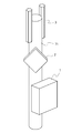
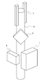
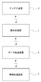
- FIG. 1 is a schematic diagram illustrating an installation example of the base station system according to the present embodiment.
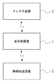
- FIG. 2 is a block diagram illustrating a state of wireless connection among the base station device 1, the wireless transmission device 2, and the antenna device 3 included in the base station system according to the present embodiment.
- the base station system includes a base station device 1, a wireless transmission device 2, and an antenna device 3, each of which can be installed outdoors.
- Base station apparatus 1 communicates with a plurality of mobile stations in a cell.
- the base station apparatus 1 is, for example, a UTRAN (UMTS Terrestrial Radio Access Network) base station (i.e., NodeB) or an E-UTRAN (Evolved UTRAN) base station (i.e., eNB).
- UTRAN UMTS Terrestrial Radio Access Network
- NodeB NodeB
- E-UTRAN Evolved UTRAN
- the wireless transmission device 2 is configured to communicate with the base station device 1 and wirelessly communicate with an opposite device (not shown) in order to connect the base station device 1 to the mobile backhaul network.
- the wireless transmission device 2 and the opposite device (not shown) are, for example, a point-to-point wireless system using microwaves or millimeter waves.
- the wireless transmission device 2 uses a carrier wave having a frequency of 6 GHz to 90 GHz, has a bidirectional transmission capacity of about 100 Mbit / s to 10 Gbit / s, and has a transmission distance of several hundred m to several tens km. Have.
- the antenna device 3 includes an antenna for the base station device 1 to communicate with a plurality of mobile stations.
- the antenna device 3 may be a wireless device called RRH (Remote Radio Radio Head) or RE (Radio Radio Equipment). More specifically, the antenna device 3 performs communication and digital signal processing (for example, filtering) with the base station device 1 using a standard interface such as OBSAI (Open Base Station Architecture Initiative) or CPRI (Common Public Radio Interface). Digital circuitry and analog circuitry for frequency conversion and amplification may be included.
- the base station apparatus 1 corresponds to BBU (Base Band Unit) or REC (Radio Equipment Controller), and performs overall control and monitoring of the radio base station, communication with the mobile core network, scheduling, and digital baseband Perform signal processing.
- BBU Base Band Unit
- REC Radio Equipment Controller
- each of the base station device 1, the wireless transmission device 2, and the antenna device 3 includes a solar cell panel and a storage battery for generating operating power of each device.
- each of the base station apparatus 1, the wireless transmission apparatus 2, and the antenna apparatus 3 does not require the connection of the power cable for receiving power supply from the outside.
- the base station device 1 and the wireless transmission device 2 are configured to communicate with each other wirelessly, and the base station device 1 and the antenna device 3 are also configured to wirelessly communicate with each other.
- the wireless communication between the base station device 1 and the wireless transmission device 2 and the wireless communication between the base station device 1 and the antenna device 3 are performed using, for example, a wireless LAN (Local Area Network) interface compliant with the IEEE 802.11 standard.
- a wireless LAN Local Area Network
- a communication cable for example, an optical fiber cable, a coaxial cable, or a twisted pair cable
- a communication cable for example, an optical fiber cable, a coaxial cable, or a twisted pair cable
- the base station system according to the present embodiment can reduce the load of installation work. This is because, for the base station device 1, the wireless transmission device 2, and the antenna device 3, a connection work for a communication cable for communication between these devices becomes unnecessary, and power is supplied to these devices from the outside. This is because no power cable connection work is required. Furthermore, the base station system according to the present embodiment can reduce the possibility that it becomes difficult to provide the communication service by the base station due to accidental or malicious damage to the communication cable or the power cable. This is because the communication cables and power cables exposed to the outside of the base station device 1, the wireless transmission device 2, and the antenna device 3 can be reduced.
- the base station system obtains power necessary for connecting the base station device 1 to the mobile backhaul network and providing the cellular communication service by the base station device 1 by power generation by the solar cell panel. Can do. Accordingly, the cellular communication service can be provided even in an area where it is difficult to receive power supply from the outside (for example, a desert area, a remote island, etc.).
- the base station device 1, the wireless transmission device 2, and the antenna device 3 are attached to a cylindrical column surface 71. Since all of these devices 1 to 3 can be attached to the wall surface or the column surface, the degree of freedom in installing the base station system can be further improved.
- the example of FIG. 1 shows a layout in which the three devices 1 to 3 are attached to one pillar surface 71 in close proximity to each other, but such a layout is only an example.
- the wireless transmission device 2 and the antenna device 3 may be attached to the pillar surface 71, and the base station device 1 may be attached to another place (for example, an outer wall surface of a building).
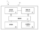
- FIG. 3 is a block diagram illustrating a configuration example of the base station apparatus 1.
- the base station device 1 has a housing 10.
- the case 10 has a dustproof and waterproof property that can be installed outdoors, and accommodates a base station device 11, a wireless LAN device 12, a power supply unit 13, a storage battery 14, and a solar cell panel 15 therein.
- the solar cell panel 15 when the solar cell panel 15 is accommodated in the housing 10, at least a part of the housing 10 (that is, a portion that becomes a light incident path to the solar cell panel 15) can generate power from the solar cell panel 15. It is good to be comprised with the member which fully permeate
- the solar cell panel 15 may be attached to the outside of the housing 10.
- the base station device 11 is a communication device that operates as a base station.
- the wireless LAN device 12 is a communication device that performs wireless communication with the wireless transmission device 2 and the antenna device 3.
- the antenna of the wireless LAN device 12 may be attached to the outside of the housing 10.
- the communication device for communication with the wireless transmission device 2 and the communication device for communication with the antenna device 3 may be one common communication device or two independent communication devices. It may be.
- the power supply unit 13 is connected to the storage battery 14 and is configured to supply the power stored in the storage battery 14 to the base station device 11 and the wireless LAN device 12. Furthermore, the power supply unit 13 is configured to charge the storage battery 14 with the power generated by the solar battery panel 15.
- FIG. 4 is a block diagram illustrating a configuration example of the wireless transmission device 2.
- the wireless transmission device 2 includes a housing 20.
- the housing 20 has dustproof and waterproof properties that can be installed outdoors, and houses a point-to-point wireless device 21, a wireless LAN device 22, a power supply unit 23, a storage battery 24, and a solar cell panel 25 therein.
- the solar cell panel 25 When the solar cell panel 25 is accommodated in the housing 20, at least a part of the housing 20 (that is, a portion that becomes a light incident path to the solar cell panel 25) can generate power from the solar cell panel 25. It is good to be comprised with the member which fully permeate
- the point-to-point wireless device 21 is a communication device that wirelessly communicates with an opposite device (not shown) in order to connect the base station device 1 to the mobile backhaul network.
- the wireless LAN device 22 is a communication device that performs wireless communication with the base station device 1.
- the antenna of the point-to-point wireless device 21 may be attached to the outside of the housing 20.
- the antenna of the wireless LAN device 22 may be attached to the outside of the housing 20.
- the power supply unit 23 is connected to the storage battery 24 and is configured to supply the power stored in the storage battery 24 to the point-to-point wireless device 21 and the wireless LAN device 22. Furthermore, the power supply unit 23 is configured to charge the storage battery 24 with the power generated by the solar battery panel 25.
- FIG. 5 is a block diagram illustrating a configuration example of the antenna device 3.
- the antenna device 3 includes a housing 30.
- the housing 30 has dustproof and waterproof properties that can be installed outdoors, and accommodates therein an antenna device 31, a wireless LAN device 32, a power supply unit 33, a storage battery 34, and a solar battery panel 35.
- the solar cell panel 35 when the solar cell panel 35 is accommodated in the housing 30, at least a part of the housing 30 (that is, a portion serving as a light incident path to the solar cell panel 25) can generate power from the solar cell panel 35. It is good to be comprised with the member which fully permeate
- the antenna device 31 includes an antenna and a signal processing unit for the base station apparatus 1 to communicate with a plurality of mobile stations.
- An antenna included in the antenna device 31 may be attached to the outside of the housing 30.
- the signal processing unit included in the antenna device 31 may have the above-described RRH (or RE) function.
- the signal processing unit included in the antenna device 31 may communicate with the base station apparatus 1 via the wireless LAN device 32 using, for example, a standard interface (such as OBSAI or CPRI) between the RRH and the BBU.
- the wireless LAN device 32 is a communication device that wirelessly communicates with the base station device 1.
- the antenna of the wireless LAN device 32 may be attached to the outside of the housing 30.
- the power supply unit 33 is connected to the storage battery 34, and is configured to supply the power stored in the storage battery 34 to the antenna device 31 and the wireless LAN device 32. Furthermore, the power supply unit 33 is configured to charge the storage battery 34 with the power generated by the solar battery panel 35.
- the dustproof and waterproof performance of the casings 10, 20, and 30 described above may be, for example, a performance corresponding to IP65 in IEC60529 defined by IEC (International Electrotechnical Commission).
- each of the base station device 1, the wireless transmission device 2, and the antenna device 3 is integrated in a casing 10, 20, or 30 that can be installed outdoors. And it has a miniaturized structure.
- the base station device 1, the wireless transmission device 2, and the antenna device 3 do not require connection of a power cable to each device and connection of a communication cable between these devices. Therefore, according to the configuration examples shown in FIGS. 3 to 5, it is possible to provide a base station system that is excellent in environmental resistance performance and ease of installation, and has high resistance to cable damage.
- FIGS. 3 to 5 can obtain electric power necessary for the operation of each device by power generation using a solar cell panel. Accordingly, these devices connect the base station device 1 to the mobile backhaul network in an area where it is difficult to receive external power supply (for example, a desert region, a remote island, etc.), and the cellular communication by the base station device 1 It can be used to enable the provision of services.
- external power supply for example, a desert region, a remote island, etc.
- FIG. 6 is a schematic diagram illustrating an installation example of the base station system according to the present embodiment.
- the base station system according to the present embodiment includes a data transfer device 4 in addition to the base station device 1, the wireless transmission device 2, and the antenna device 3 described above.
- the data transfer device 4 performs transfer processing of data packets or data frames (for example, IP packets, MAC (Media Access Control) frames).
- the data transfer device 4 is, for example, a router, a layer 3 switch, or a layer 2 switch.
- the data transfer device 4 is also configured to be installed outdoors.
- FIG. 7 is a block diagram illustrating a state of wireless connection among the base station device 1, the wireless transmission device 2, the antenna device 3, and the data transfer device 4 included in the base station system according to the present embodiment.
- the data transfer device 4 transfers data packets or data frames between the base station device 1 and the wireless transmission device 2.
- the base station device 1 and the data transfer device 4 are configured to wirelessly communicate with each other using, for example, a wireless LAN interface.
- the wireless transmission device 2 and the data transfer device 4 are configured to wirelessly communicate with each other using, for example, a wireless LAN interface.
- a communication cable for example, an optical fiber cable, a coaxial cable, or a twisted pair cable
- a communication cable for example, an optical fiber cable, a coaxial cable, or a twisted pair cable
- the data transfer device 4 has a solar battery panel and a storage battery for generating the operating power of the data transfer device 4. As a result, the data transfer device 4 does not require connection of a power cable for receiving power supply from the outside, like the devices 1 to 3.
- the base station system according to the present embodiment can reduce the load of installation work as in the first embodiment. Furthermore, the base station system according to the present embodiment can reduce the possibility that it becomes difficult to provide the communication service by the base station due to accidental or malicious damage to the communication cable or the power cable.
- the configurations of the base station device 1, the wireless transmission device 2, and the antenna device 3 may be the same as the configuration examples of FIGS. 3 to 5 described in the first embodiment.
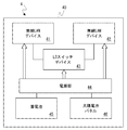
- FIG. 8 is a block diagram illustrating a configuration example of the data transfer device 4.
- the data transfer device 4 has a housing 40.
- the case 40 has dustproof and waterproof properties that can be installed outdoors, and includes a wireless LAN device 41, a wireless LAN device 42, a layer 3 switch device 43, a power supply unit 44, a storage battery 45, and a solar cell panel 46 therein. Contained.
- the solar cell panel 46 When the solar cell panel 46 is accommodated in the housing 40, at least a part of the housing 40 (that is, a portion that becomes a light incident path to the solar cell panel 46) can generate power from the solar cell panel 46. It is good to be comprised with the member which fully permeate
- the wireless LAN device 41 is a communication device that wirelessly communicates with the base station apparatus 1.
- the wireless LAN device 42 is a communication device that performs wireless communication with the wireless transmission device 2.
- the layer 3 switch device 43 transfers the IP packet between the base station device 1 and the wireless transmission device 2 via the wireless LAN devices 41 and 42.
- the antennas of the wireless LAN devices 41 and 42 may be attached to the outside of the housing 40.
- the power supply unit 44 is connected to the storage battery 45 and is configured to supply the power stored in the storage battery 45 to the wireless LAN devices 41 and 42 and the layer 3 switch device 43. Furthermore, the power supply unit 44 is configured to charge the storage battery 45 with the power generated by the solar battery panel 46.
- the data transfer device 4 has an integrated and downsized structure housed in a case 40 that can be installed outdoors.
- the data transfer device 4 does not require connection of a power cable, and does not require connection of a communication cable between the base station device 1 and the wireless transmission device 2. Therefore, according to the configuration example shown in FIG. 8, it is possible to provide a base station system that is excellent in environmental resistance performance and ease of installation, and that has high resistance to cable damage.
- FIG. 9 is a modification of the configuration example illustrated in FIG. 1, and illustrates a configuration in which the antenna 16 is directly attached to the housing of the base station apparatus 1.
- wireless communication between the base station device 1 and the antenna device 3 as described in the first and second embodiments is not necessary.
- ⁇ Other embodiments> In the first to third embodiments, an example in which one base station device 1 and one wireless transmission device 2 are used has been described. However, for example, when the traffic demand at the place where the base station system is installed is large, a plurality of base station apparatuses 1 may be installed. In this case, one wireless transmission device 2 may be used to connect a plurality of base station devices 1 to the mobile backhaul network. At this time, the multiplexing of the traffic related to the plurality of base station apparatuses 1 may be performed by packet (frame) multiplexing in the data transfer apparatus 4 or by using the multiplexing function of the radio transmission apparatus 2. Also good. Further, for example, when the connection with the mobile backhaul network is made redundant, or when the traffic of the base station arranged at another installation location is relayed, a plurality of wireless transmission devices 2 may be installed. Good.
Landscapes
- Engineering & Computer Science (AREA)
- Computer Networks & Wireless Communication (AREA)
- Signal Processing (AREA)
- Power Engineering (AREA)
- Databases & Information Systems (AREA)
- Mobile Radio Communication Systems (AREA)
- Charge And Discharge Circuits For Batteries Or The Like (AREA)
Abstract
Description
図1は、本実施形態に係る基地局システムの設置例を示す模式図である。図2は、本実施形態に係る基地局システムに含まれる基地局装置1、無線伝送装置2、及びアンテナ装置3の間の無線接続の様子を示すブロック図である。
本実施形態では、第1の実施形態に係る基地局システムの変形例について説明する。図6は、本実施形態に係る基地局システムの設置例を示す模式図である。本実施形態に係る基地局システムは、上述した基地局装置1、無線伝送装置2、及びアンテナ装置3に加えて、データ転送装置4を含む。データ転送装置4は、データパケット又はデータフレーム(例えば、IPパケット、MAC(Media Access Control)フレーム)の転送処理を行う。データ転送装置4は、例えば、ルータ、レイヤ3スイッチ、又はレイヤ2スイッチである。データ転送装置4も、屋外設置可能に構成されている。
上述の第1及び第2の実施形態では、アンテナ装置3が基地局装置1から分離している構成を示した。しかしながら、第1及び第2の実施形態において、基地局装置1が複数の移動局と通信するためのアンテナは、基地局装置1の筐体に取り付けられてもよい。図9に示された構成例は、図1に示された構成例の変形であり、基地局装置1の筐体にアンテナ16が直接的に取り付けられた構成を示している。図9の構成例では、第1及び第2の実施形態で説明したような基地局装置1とアンテナ装置3の間の無線通信は不要である。
第1~第3の形態では、1台の基地局装置1と1台の無線伝送装置2が用いられる例を示した。しかしながら、例えば、基地局システムの設置場所におけるトラフィック需要が大きい場合には、複数台の基地局装置1が設置されてもよい。この場合、複数台の基地局装置1をモバイルバックホールネットワークに接続するために1台の無線伝送装置2が使用されてもよい。このとき、複数台の基地局装置1に関するトラフィックの多重化は、データ転送装置4におけるパケット(フレーム)多重化により行なわれてもよいし、無線伝送装置2の多重化機能を用いて行なわれてもよい。また、例えば、モバイルバックホールネットワークとの接続が冗長化される場合、又は他の設置場所に配置された基地局のトラフィックを中継する場合には、複数台の無線伝送装置2が設置されてもよい。
2 無線伝送装置
3 アンテナ装置
4 データ転送装置
10、20、30、40 筐体
11 基地局デバイス
12、22、32、41、42 無線LANデバイス
13、23、33、44 電源部
14、24、34、45 蓄電池
15、25、35、46 太陽電池パネル
16 アンテナ
21 ポイントツーポイント無線デバイス
31 アンテナデバイス
43 レイヤ3スイッチデバイス
Claims (14)
- 複数の移動局と通信する基地局装置と、
前記基地局装置をモバイルバックホールネットワークに接続するために、前記基地局装置と通信すると共に、対向装置と無線通信する無線伝送装置と、
を備え、
前記基地局装置は、前記基地局装置の動作電力を生成するための第1の太陽電池パネル及び第1の蓄電池を備え、
前記無線伝送装置は、前記無線伝送装置の動作電力を生成するための第2の太陽電池パネル及び第2の蓄電池を備え、
前記基地局装置及び前記無線伝送装置は、互いに無線通信するよう構成されている、
基地局システム。 - 前記基地局装置と前記無線伝送装置の間は、通信ケーブルの接続を必要とせず、
前記基地局装置及び前記無線伝送装置の各々は、外部から電力供給を受けるための電源ケーブルの接続を必要としない、
請求項1に記載の基地局システム。 - 前記複数の移動局と通信するためのアンテナ装置をさらに備え、
前記アンテナ装置は、前記アンテナ装置の動作電力を生成するための第3の太陽電池パネル及び第3の蓄電池を備え、
前記基地局装置及び前記アンテナ装置は互いに無線通信するよう構成されている、
請求項1又は2に記載の基地局システム。 - 前記基地局装置と前記アンテナ装置の間は、通信ケーブルの接続を必要とせず、
前記アンテナ装置は、外部から電力供給を受けるための電源ケーブルの接続を必要としない、
請求項3に記載の基地局システム。 - 前記基地局装置は、屋外設置可能な防塵性及び防水性を有し、前記第1の蓄電池、基地局として動作する通信機器、及び前記無線伝送装置と無線通信するための通信機器をその内部に収容し、且つ前記第1の太陽電池パネルが取り付けられた第1の筐体をさらに備え、
前記無線伝送装置は、屋外設置可能な防塵性及び防水性を有し、前記第2の蓄電池、前記対向装置と無線通信するための通信機器、及び前記基地局装置と無線通信するための通信機器をその内部に収容し、且つ前記第2の太陽電池パネルが取り付けられた第2の筐体をさらに備える、
請求項1~4のいずれか1項に記載の基地局システム。 - 前記基地局装置は、屋外設置可能な防塵性及び防水性を有すると共に、前記第1の太陽電池パネル、前記第1の蓄電池、基地局として動作する通信機器、及び前記無線伝送装置と無線通信するための通信機器をその内部に収容する第1の筐体をさらに備え、
前記無線伝送装置は、屋外設置可能な防塵性及び防水性を有すると共に、前記第2の太陽電池パネル、前記第2の蓄電池、前記対向装置と無線通信するための通信機器、及び前記基地局装置と無線通信するための通信機器をその内部に収容する第2の筐体をさらに備える、
請求項1~4のいずれか1項に記載の基地局システム。 - 複数の移動局と通信する基地局装置と、
前記基地局装置をモバイルバックホールネットワークに接続するために、対向装置と無線通信する無線伝送装置と、
前記基地局装置と前記無線伝送装置の間でデータパケット又はデータフレームを転送するデータ転送装置と、
を備え、
前記基地局装置は、前記基地局装置の動作電力を生成するための第1の太陽電池パネル及び第1の蓄電池を備え、
前記無線伝送装置は、前記無線伝送装置の動作電力を生成するための第2の太陽電池パネル及び第2の蓄電池を備え、
前記データ転送装置は、前記データ転送装置の動作電力を生成するための第3の太陽電池パネル及び第3の蓄電池を備え、
前記基地局装置及び前記データ転送装置は、互いに無線通信するよう構成され、
前記無線伝送装置及びデータ転送装置は、互いに無線通信するよう構成されている、
基地局システム。 - 前記基地局装置と前記データ転送装置の間は、通信ケーブルの接続を必要とせず、
前記無線伝送装置と前記データ転送装置の間は、通信ケーブルの接続を必要とせず、
前記基地局装置、前記無線伝送装置、前記データ転送装置の各々は、外部から電力供給を受けるための電源ケーブルの接続を必要としない、
請求項7に記載の基地局システム。 - 前記複数の移動局と通信するためのアンテナ装置をさらに備え、
前記アンテナ装置は、前記アンテナ装置の動作電力を生成するための第4の太陽電池パネル及び第4の蓄電池を備え、
前記基地局装置及び前記アンテナ装置は互いに無線通信するよう構成されている、
請求項7又は8に記載の基地局システム。 - 前記基地局装置と前記アンテナ装置の間は、通信ケーブルの接続を必要とせず、
前記アンテナ装置は、外部から電力供給を受けるための電源ケーブルの接続を必要としない、
請求項9に記載の基地局システム。 - 前記基地局装置は、屋外設置可能な防塵性及び防水性を有し、前記第1の蓄電池、基地局として動作する通信機器、及び前記無線伝送装置と無線通信するための通信機器をその内部に収容し、且つ前記第1の太陽電池パネルが取り付けられた第1の筐体をさらに備え、
前記無線伝送装置は、屋外設置可能な防塵性及び防水性を有し、前記第2の蓄電池、前記対向装置と無線通信するための通信機器、及び前記基地局装置と無線通信するための通信機器をその内部に収容し、且つ前記第2の太陽電池パネルが取り付けられた第2の筐体をさらに備え、
前記データ転送装置は、屋外設置可能な防塵性及び防水性を有し、前記第3の蓄電池、前記基地局装置と無線通信するための通信機器、及び前記無線伝送装置と無線通信するための通信機器をその内部に収容し、且つ前記第3の太陽電池パネルが取り付けられた第3の筐体をさらに備える、
請求項7~10のいずれか1項に記載の基地局システム。 - 前記基地局装置は、屋外設置可能な防塵性及び防水性を有すると共に、前記第1の太陽電池パネル、前記第1の蓄電池、基地局として動作する通信機器、及び前記データ転送装置と無線通信するための通信機器をその内部に収容する第1の筐体をさらに備え、
前記無線伝送装置は、屋外設置可能な防塵性及び防水性を有すると共に、前記第2の太陽電池パネル、前記第2の蓄電池、前記対向装置と無線通信するための通信機器、及び前記データ転送装置と無線通信するための通信機器をその内部に収容する第2の筐体をさらに備え、
前記データ転送装置は、屋外設置可能な防塵性及び防水性を有すると共に、前記第3の太陽電池パネル、前記第3の蓄電池、前記基地局装置と無線通信するための通信機器、及び前記無線伝送装置と無線通信するための通信機器をその内部に収容する第3の筐体をさらに備える、
請求項7~10のいずれか1項に記載の基地局システム。 - モバイルバックホールネットワークに用いられる無線伝送装置であって、
対向装置と無線伝送するポイントツーポイント無線デバイスと、
基地局と無線通信する無線LAN(Local Area Network)デバイスと、
太陽電池パネルと、
蓄電池と、
前記太陽電池パネル及び前記蓄電池と結合され、前記ポイントツーポイント無線デバイス及び前記無線LANデバイスに電力を供給する電源部と、
防水性および防塵性を有し、前記ポイントツーポイント無線デバイス、前記無線LANデバイス、前記蓄電池、及び前記電源部をその内部に収容するとともに、前記太陽電池パネルと結合された筐体と、
を備える、無線伝送装置。 - 前記筐体は、前記太陽電池パネルをその内部に収容している、請求項13に記載の無線伝送装置。
Priority Applications (3)
| Application Number | Priority Date | Filing Date | Title |
|---|---|---|---|
| RU2016103588A RU2615746C1 (ru) | 2013-08-06 | 2014-07-15 | Система базовой станции и беспроводное оборудование передачи |
| EP14834571.3A EP3032750A4 (en) | 2013-08-06 | 2014-07-15 | Base station system and radio transmission apparatus |
| US14/903,204 US9716998B2 (en) | 2013-08-06 | 2014-07-15 | Base station system and wireless transmission apparatus |
Applications Claiming Priority (2)
| Application Number | Priority Date | Filing Date | Title |
|---|---|---|---|
| JP2013163465 | 2013-08-06 | ||
| JP2013-163465 | 2013-08-06 |
Publications (1)
| Publication Number | Publication Date |
|---|---|
| WO2015019554A1 true WO2015019554A1 (ja) | 2015-02-12 |
Family
ID=52460916
Family Applications (1)
| Application Number | Title | Priority Date | Filing Date |
|---|---|---|---|
| PCT/JP2014/003745 Ceased WO2015019554A1 (ja) | 2013-08-06 | 2014-07-15 | 基地局システム及び無線伝送装置 |
Country Status (4)
| Country | Link |
|---|---|
| US (1) | US9716998B2 (ja) |
| EP (1) | EP3032750A4 (ja) |
| RU (1) | RU2615746C1 (ja) |
| WO (1) | WO2015019554A1 (ja) |
Families Citing this family (5)
| Publication number | Priority date | Publication date | Assignee | Title |
|---|---|---|---|---|
| CN105846045A (zh) * | 2016-04-28 | 2016-08-10 | 哈尔滨金都太阳能科技有限公司 | 一种太阳能基站通讯天线 |
| DE102017001543A1 (de) * | 2017-02-16 | 2018-08-16 | Kathrein-Werke Kg | Antenne, insbesondere Mobilfunkantenne |
| US20180359023A1 (en) * | 2017-06-09 | 2018-12-13 | Keysight Technologies, Inc. | System integration of solar panels/cells and antennas (span system) |
| CN108448627A (zh) * | 2018-04-12 | 2018-08-24 | 唐山新质点科技有限公司 | 太阳能自供电无线微基站及信息管理系统 |
| EP3788672A1 (en) * | 2018-05-03 | 2021-03-10 | Telefonaktiebolaget LM Ericsson (publ) | Outdoor radio units with integrated solar cells |
Citations (6)
| Publication number | Priority date | Publication date | Assignee | Title |
|---|---|---|---|---|
| JPH10190554A (ja) * | 1996-12-24 | 1998-07-21 | Nec Corp | Phs基地局とphs基地局の給電方法 |
| JPH10336094A (ja) | 1997-05-28 | 1998-12-18 | Hitachi Electron Service Co Ltd | 構内phs基地局 |
| JP2003332971A (ja) * | 2002-05-09 | 2003-11-21 | Advanced Telecommunication Research Institute International | 無線ネットワークのための通信方法及び無線ネットワークシステム |
| JP2008122247A (ja) * | 2006-11-13 | 2008-05-29 | Toshiba Corp | アレイアンテナシステム |
| JP2011119964A (ja) * | 2009-12-03 | 2011-06-16 | Nec Access Technica Ltd | 路側機及び路車間通信システム |
| JP2012253621A (ja) | 2011-06-03 | 2012-12-20 | Nippon Telegr & Teleph Corp <Ntt> | 基地局装置 |
Family Cites Families (14)
| Publication number | Priority date | Publication date | Assignee | Title |
|---|---|---|---|---|
| US20120296974A1 (en) * | 1999-04-27 | 2012-11-22 | Joseph Akwo Tabe | Social network for media topics of information relating to the science of positivism |
| US8588830B2 (en) * | 2007-02-02 | 2013-11-19 | Inovus Solar, Inc | Wireless autonomous solar-powered outdoor lighting and energy and information management network |
| EP2083170A1 (en) * | 2008-01-23 | 2009-07-29 | Flexenclosure AB | Method and device for controlling operation of a power supply system |
| DE102008014633B4 (de) * | 2008-03-17 | 2010-10-14 | Siemens Aktiengesellschaft | Verfahren zum Betreiben eines drahtlosen Sensornetzwerks und Sensorknoten |
| US20090272803A1 (en) * | 2008-05-05 | 2009-11-05 | Intelliwave Technologies Inc. | Sensor network for managing the location of materials on a construction site |
| WO2011059544A1 (en) * | 2009-11-16 | 2011-05-19 | Front Row Technologies, Llc | Self-contained data communication system nodes as stand-alone pods or embedded in concrete walkways and in walls at public venues including sports and entertainment venues |
| KR101646970B1 (ko) * | 2010-04-22 | 2016-08-10 | 삼성전자주식회사 | 태양광 전지를 사용하는 휴대용 단말기의 배터리 충전 장치 및 방법 |
| US9253816B1 (en) * | 2011-06-30 | 2016-02-02 | The Boeing Company | Self-contained area network system |
| US20130142136A1 (en) * | 2011-10-21 | 2013-06-06 | Samsung Electronics Co., Ltd. | Methods and apparatus for adaptive wireless backhaul and networks |
| ZA201308867B (en) * | 2012-11-26 | 2016-01-27 | Brightsource Ind (Israel|) Ltd | Systems and methods for operating a wirelessly controlled solar field |
| US9894852B2 (en) * | 2013-01-08 | 2018-02-20 | Semiosbio Technologies Inc. | Monitoring and control systems for the agricultural industry |
| US20140314062A1 (en) * | 2013-04-19 | 2014-10-23 | Dennis Loebs | Aquatic-Based Automation Systems |
| US9079719B2 (en) * | 2013-09-30 | 2015-07-14 | Laitram, L.L.C. | Positive-drive spiral conveyor with overlapping cage-bar caps |
| CN104494545B (zh) * | 2014-11-14 | 2016-09-14 | 上海盈达空调设备有限公司 | 太阳能车载冷库系统 |
-
2014
- 2014-07-15 WO PCT/JP2014/003745 patent/WO2015019554A1/ja not_active Ceased
- 2014-07-15 RU RU2016103588A patent/RU2615746C1/ru not_active IP Right Cessation
- 2014-07-15 US US14/903,204 patent/US9716998B2/en not_active Expired - Fee Related
- 2014-07-15 EP EP14834571.3A patent/EP3032750A4/en not_active Withdrawn
Patent Citations (6)
| Publication number | Priority date | Publication date | Assignee | Title |
|---|---|---|---|---|
| JPH10190554A (ja) * | 1996-12-24 | 1998-07-21 | Nec Corp | Phs基地局とphs基地局の給電方法 |
| JPH10336094A (ja) | 1997-05-28 | 1998-12-18 | Hitachi Electron Service Co Ltd | 構内phs基地局 |
| JP2003332971A (ja) * | 2002-05-09 | 2003-11-21 | Advanced Telecommunication Research Institute International | 無線ネットワークのための通信方法及び無線ネットワークシステム |
| JP2008122247A (ja) * | 2006-11-13 | 2008-05-29 | Toshiba Corp | アレイアンテナシステム |
| JP2011119964A (ja) * | 2009-12-03 | 2011-06-16 | Nec Access Technica Ltd | 路側機及び路車間通信システム |
| JP2012253621A (ja) | 2011-06-03 | 2012-12-20 | Nippon Telegr & Teleph Corp <Ntt> | 基地局装置 |
Non-Patent Citations (1)
| Title |
|---|
| See also references of EP3032750A4 |
Also Published As
| Publication number | Publication date |
|---|---|
| US20160192183A1 (en) | 2016-06-30 |
| RU2615746C1 (ru) | 2017-04-11 |
| EP3032750A4 (en) | 2017-02-15 |
| US9716998B2 (en) | 2017-07-25 |
| EP3032750A1 (en) | 2016-06-15 |
Similar Documents
| Publication | Publication Date | Title |
|---|---|---|
| JP6930674B2 (ja) | システム及び方法 | |
| US20160007488A1 (en) | Connection box, main box, and base station transceiver | |
| WO2015019554A1 (ja) | 基地局システム及び無線伝送装置 | |
| TW201603625A (zh) | 可升級高資料傳輸速率多頻道傳輸系統 | |
| US8116821B2 (en) | System and antenna for radio access networks | |
| US20180131401A1 (en) | Wireless sfp module | |
| CN216873401U (zh) | 通信装置 | |
| WO2016184158A1 (zh) | 室分系统及其工作方法 | |
| US20250150856A1 (en) | Communication arrangement | |
| CN106941357B (zh) | 基于软件定义的无线电的组网方法、系统 | |
| WO2022197150A1 (ko) | 무선 통신 시스템에서 서비스 네트워크를 제공하기 위한 장치 및 방법 | |
| US8750171B2 (en) | Femtocell/WLAN communication device |
Legal Events
| Date | Code | Title | Description |
|---|---|---|---|
| 121 | Ep: the epo has been informed by wipo that ep was designated in this application |
Ref document number: 14834571 Country of ref document: EP Kind code of ref document: A1 |
|
| WWE | Wipo information: entry into national phase |
Ref document number: 14903204 Country of ref document: US |
|
| WWE | Wipo information: entry into national phase |
Ref document number: IDP00201600718 Country of ref document: ID Ref document number: 2014834571 Country of ref document: EP |
|
| NENP | Non-entry into the national phase |
Ref country code: DE |
|
| ENP | Entry into the national phase |
Ref document number: 2016103588 Country of ref document: RU Kind code of ref document: A |
|
| NENP | Non-entry into the national phase |
Ref country code: JP |