WO2015019582A1 - 電力供給システム、放電装置 - Google Patents
電力供給システム、放電装置 Download PDFInfo
- Publication number
- WO2015019582A1 WO2015019582A1 PCT/JP2014/004011 JP2014004011W WO2015019582A1 WO 2015019582 A1 WO2015019582 A1 WO 2015019582A1 JP 2014004011 W JP2014004011 W JP 2014004011W WO 2015019582 A1 WO2015019582 A1 WO 2015019582A1
- Authority
- WO
- WIPO (PCT)
- Prior art keywords
- power
- amount
- battery
- unit
- customer
- Prior art date
- Legal status (The legal status is an assumption and is not a legal conclusion. Google has not performed a legal analysis and makes no representation as to the accuracy of the status listed.)
- Ceased
Links
Images


Classifications
-
- B—PERFORMING OPERATIONS; TRANSPORTING
- B60—VEHICLES IN GENERAL
- B60L—PROPULSION OF ELECTRICALLY-PROPELLED VEHICLES; SUPPLYING ELECTRIC POWER FOR AUXILIARY EQUIPMENT OF ELECTRICALLY-PROPELLED VEHICLES; ELECTRODYNAMIC BRAKE SYSTEMS FOR VEHICLES IN GENERAL; MAGNETIC SUSPENSION OR LEVITATION FOR VEHICLES; MONITORING OPERATING VARIABLES OF ELECTRICALLY-PROPELLED VEHICLES; ELECTRIC SAFETY DEVICES FOR ELECTRICALLY-PROPELLED VEHICLES
- B60L53/00—Methods of charging batteries, specially adapted for electric vehicles; Charging stations or on-board charging equipment therefor; Exchange of energy storage elements in electric vehicles
- B60L53/10—Methods of charging batteries, specially adapted for electric vehicles; Charging stations or on-board charging equipment therefor; Exchange of energy storage elements in electric vehicles characterised by the energy transfer between the charging station and the vehicle
- B60L53/14—Conductive energy transfer
-
- B—PERFORMING OPERATIONS; TRANSPORTING
- B60—VEHICLES IN GENERAL
- B60L—PROPULSION OF ELECTRICALLY-PROPELLED VEHICLES; SUPPLYING ELECTRIC POWER FOR AUXILIARY EQUIPMENT OF ELECTRICALLY-PROPELLED VEHICLES; ELECTRODYNAMIC BRAKE SYSTEMS FOR VEHICLES IN GENERAL; MAGNETIC SUSPENSION OR LEVITATION FOR VEHICLES; MONITORING OPERATING VARIABLES OF ELECTRICALLY-PROPELLED VEHICLES; ELECTRIC SAFETY DEVICES FOR ELECTRICALLY-PROPELLED VEHICLES
- B60L53/00—Methods of charging batteries, specially adapted for electric vehicles; Charging stations or on-board charging equipment therefor; Exchange of energy storage elements in electric vehicles
- B60L53/10—Methods of charging batteries, specially adapted for electric vehicles; Charging stations or on-board charging equipment therefor; Exchange of energy storage elements in electric vehicles characterised by the energy transfer between the charging station and the vehicle
- B60L53/11—DC charging controlled by the charging station, e.g. mode 4
-
- B—PERFORMING OPERATIONS; TRANSPORTING
- B60—VEHICLES IN GENERAL
- B60L—PROPULSION OF ELECTRICALLY-PROPELLED VEHICLES; SUPPLYING ELECTRIC POWER FOR AUXILIARY EQUIPMENT OF ELECTRICALLY-PROPELLED VEHICLES; ELECTRODYNAMIC BRAKE SYSTEMS FOR VEHICLES IN GENERAL; MAGNETIC SUSPENSION OR LEVITATION FOR VEHICLES; MONITORING OPERATING VARIABLES OF ELECTRICALLY-PROPELLED VEHICLES; ELECTRIC SAFETY DEVICES FOR ELECTRICALLY-PROPELLED VEHICLES
- B60L53/00—Methods of charging batteries, specially adapted for electric vehicles; Charging stations or on-board charging equipment therefor; Exchange of energy storage elements in electric vehicles
- B60L53/30—Constructional details of charging stations
- B60L53/305—Communication interfaces
-
- B—PERFORMING OPERATIONS; TRANSPORTING
- B60—VEHICLES IN GENERAL
- B60L—PROPULSION OF ELECTRICALLY-PROPELLED VEHICLES; SUPPLYING ELECTRIC POWER FOR AUXILIARY EQUIPMENT OF ELECTRICALLY-PROPELLED VEHICLES; ELECTRODYNAMIC BRAKE SYSTEMS FOR VEHICLES IN GENERAL; MAGNETIC SUSPENSION OR LEVITATION FOR VEHICLES; MONITORING OPERATING VARIABLES OF ELECTRICALLY-PROPELLED VEHICLES; ELECTRIC SAFETY DEVICES FOR ELECTRICALLY-PROPELLED VEHICLES
- B60L53/00—Methods of charging batteries, specially adapted for electric vehicles; Charging stations or on-board charging equipment therefor; Exchange of energy storage elements in electric vehicles
- B60L53/60—Monitoring or controlling charging stations
- B60L53/63—Monitoring or controlling charging stations in response to network capacity
-
- B—PERFORMING OPERATIONS; TRANSPORTING
- B60—VEHICLES IN GENERAL
- B60L—PROPULSION OF ELECTRICALLY-PROPELLED VEHICLES; SUPPLYING ELECTRIC POWER FOR AUXILIARY EQUIPMENT OF ELECTRICALLY-PROPELLED VEHICLES; ELECTRODYNAMIC BRAKE SYSTEMS FOR VEHICLES IN GENERAL; MAGNETIC SUSPENSION OR LEVITATION FOR VEHICLES; MONITORING OPERATING VARIABLES OF ELECTRICALLY-PROPELLED VEHICLES; ELECTRIC SAFETY DEVICES FOR ELECTRICALLY-PROPELLED VEHICLES
- B60L53/00—Methods of charging batteries, specially adapted for electric vehicles; Charging stations or on-board charging equipment therefor; Exchange of energy storage elements in electric vehicles
- B60L53/60—Monitoring or controlling charging stations
- B60L53/65—Monitoring or controlling charging stations involving identification of vehicles or their battery types
-
- B—PERFORMING OPERATIONS; TRANSPORTING
- B60—VEHICLES IN GENERAL
- B60L—PROPULSION OF ELECTRICALLY-PROPELLED VEHICLES; SUPPLYING ELECTRIC POWER FOR AUXILIARY EQUIPMENT OF ELECTRICALLY-PROPELLED VEHICLES; ELECTRODYNAMIC BRAKE SYSTEMS FOR VEHICLES IN GENERAL; MAGNETIC SUSPENSION OR LEVITATION FOR VEHICLES; MONITORING OPERATING VARIABLES OF ELECTRICALLY-PROPELLED VEHICLES; ELECTRIC SAFETY DEVICES FOR ELECTRICALLY-PROPELLED VEHICLES
- B60L53/00—Methods of charging batteries, specially adapted for electric vehicles; Charging stations or on-board charging equipment therefor; Exchange of energy storage elements in electric vehicles
- B60L53/60—Monitoring or controlling charging stations
- B60L53/66—Data transfer between charging stations and vehicles
- B60L53/665—Methods related to measuring, billing or payment
-
- B—PERFORMING OPERATIONS; TRANSPORTING
- B60—VEHICLES IN GENERAL
- B60L—PROPULSION OF ELECTRICALLY-PROPELLED VEHICLES; SUPPLYING ELECTRIC POWER FOR AUXILIARY EQUIPMENT OF ELECTRICALLY-PROPELLED VEHICLES; ELECTRODYNAMIC BRAKE SYSTEMS FOR VEHICLES IN GENERAL; MAGNETIC SUSPENSION OR LEVITATION FOR VEHICLES; MONITORING OPERATING VARIABLES OF ELECTRICALLY-PROPELLED VEHICLES; ELECTRIC SAFETY DEVICES FOR ELECTRICALLY-PROPELLED VEHICLES
- B60L55/00—Arrangements for supplying energy stored within a vehicle to a power network, i.e. vehicle-to-grid [V2G] arrangements
-
- B—PERFORMING OPERATIONS; TRANSPORTING
- B60—VEHICLES IN GENERAL
- B60L—PROPULSION OF ELECTRICALLY-PROPELLED VEHICLES; SUPPLYING ELECTRIC POWER FOR AUXILIARY EQUIPMENT OF ELECTRICALLY-PROPELLED VEHICLES; ELECTRODYNAMIC BRAKE SYSTEMS FOR VEHICLES IN GENERAL; MAGNETIC SUSPENSION OR LEVITATION FOR VEHICLES; MONITORING OPERATING VARIABLES OF ELECTRICALLY-PROPELLED VEHICLES; ELECTRIC SAFETY DEVICES FOR ELECTRICALLY-PROPELLED VEHICLES
- B60L58/00—Methods or circuit arrangements for monitoring or controlling batteries or fuel cells, specially adapted for electric vehicles
- B60L58/40—Methods or circuit arrangements for monitoring or controlling batteries or fuel cells, specially adapted for electric vehicles for controlling a combination of batteries and fuel cells
-
- H—ELECTRICITY
- H02—GENERATION; CONVERSION OR DISTRIBUTION OF ELECTRIC POWER
- H02J—ELECTRIC POWER NETWORKS; CIRCUIT ARRANGEMENTS OR SYSTEMS FOR SUPPLYING OR DISTRIBUTING ELECTRIC POWER; SYSTEMS FOR STORING ELECTRIC ENERGY
- H02J3/00—Circuit arrangements for AC mains or AC distribution networks
- H02J3/28—Arrangements for balancing of the load in networks by storage of energy
- H02J3/32—Arrangements for balancing of the load in networks by storage of energy using batteries or super capacitors with converting means
- H02J3/322—Arrangements for balancing of the load in networks by storage of energy using batteries or super capacitors with converting means the battery being on-board an electric or hybrid vehicle, e.g. vehicle to grid arrangements [V2G], power aggregation, use of the battery for network load balancing, coordinated or cooperative battery charging
-
- B—PERFORMING OPERATIONS; TRANSPORTING
- B60—VEHICLES IN GENERAL
- B60L—PROPULSION OF ELECTRICALLY-PROPELLED VEHICLES; SUPPLYING ELECTRIC POWER FOR AUXILIARY EQUIPMENT OF ELECTRICALLY-PROPELLED VEHICLES; ELECTRODYNAMIC BRAKE SYSTEMS FOR VEHICLES IN GENERAL; MAGNETIC SUSPENSION OR LEVITATION FOR VEHICLES; MONITORING OPERATING VARIABLES OF ELECTRICALLY-PROPELLED VEHICLES; ELECTRIC SAFETY DEVICES FOR ELECTRICALLY-PROPELLED VEHICLES
- B60L2200/00—Type of vehicles
- B60L2200/12—Bikes
-
- B—PERFORMING OPERATIONS; TRANSPORTING
- B60—VEHICLES IN GENERAL
- B60L—PROPULSION OF ELECTRICALLY-PROPELLED VEHICLES; SUPPLYING ELECTRIC POWER FOR AUXILIARY EQUIPMENT OF ELECTRICALLY-PROPELLED VEHICLES; ELECTRODYNAMIC BRAKE SYSTEMS FOR VEHICLES IN GENERAL; MAGNETIC SUSPENSION OR LEVITATION FOR VEHICLES; MONITORING OPERATING VARIABLES OF ELECTRICALLY-PROPELLED VEHICLES; ELECTRIC SAFETY DEVICES FOR ELECTRICALLY-PROPELLED VEHICLES
- B60L2240/00—Control parameters of input or output; Target parameters
- B60L2240/80—Time limits
-
- Y—GENERAL TAGGING OF NEW TECHNOLOGICAL DEVELOPMENTS; GENERAL TAGGING OF CROSS-SECTIONAL TECHNOLOGIES SPANNING OVER SEVERAL SECTIONS OF THE IPC; TECHNICAL SUBJECTS COVERED BY FORMER USPC CROSS-REFERENCE ART COLLECTIONS [XRACs] AND DIGESTS
- Y02—TECHNOLOGIES OR APPLICATIONS FOR MITIGATION OR ADAPTATION AGAINST CLIMATE CHANGE
- Y02E—REDUCTION OF GREENHOUSE GAS [GHG] EMISSIONS, RELATED TO ENERGY GENERATION, TRANSMISSION OR DISTRIBUTION
- Y02E60/00—Enabling technologies; Technologies with a potential or indirect contribution to GHG emissions mitigation
-
- Y—GENERAL TAGGING OF NEW TECHNOLOGICAL DEVELOPMENTS; GENERAL TAGGING OF CROSS-SECTIONAL TECHNOLOGIES SPANNING OVER SEVERAL SECTIONS OF THE IPC; TECHNICAL SUBJECTS COVERED BY FORMER USPC CROSS-REFERENCE ART COLLECTIONS [XRACs] AND DIGESTS
- Y02—TECHNOLOGIES OR APPLICATIONS FOR MITIGATION OR ADAPTATION AGAINST CLIMATE CHANGE
- Y02T—CLIMATE CHANGE MITIGATION TECHNOLOGIES RELATED TO TRANSPORTATION
- Y02T10/00—Road transport of goods or passengers
- Y02T10/60—Other road transportation technologies with climate change mitigation effect
- Y02T10/70—Energy storage systems for electromobility, e.g. batteries
-
- Y—GENERAL TAGGING OF NEW TECHNOLOGICAL DEVELOPMENTS; GENERAL TAGGING OF CROSS-SECTIONAL TECHNOLOGIES SPANNING OVER SEVERAL SECTIONS OF THE IPC; TECHNICAL SUBJECTS COVERED BY FORMER USPC CROSS-REFERENCE ART COLLECTIONS [XRACs] AND DIGESTS
- Y02—TECHNOLOGIES OR APPLICATIONS FOR MITIGATION OR ADAPTATION AGAINST CLIMATE CHANGE
- Y02T—CLIMATE CHANGE MITIGATION TECHNOLOGIES RELATED TO TRANSPORTATION
- Y02T10/00—Road transport of goods or passengers
- Y02T10/60—Other road transportation technologies with climate change mitigation effect
- Y02T10/7072—Electromobility specific charging systems or methods for batteries, ultracapacitors, supercapacitors or double-layer capacitors
-
- Y—GENERAL TAGGING OF NEW TECHNOLOGICAL DEVELOPMENTS; GENERAL TAGGING OF CROSS-SECTIONAL TECHNOLOGIES SPANNING OVER SEVERAL SECTIONS OF THE IPC; TECHNICAL SUBJECTS COVERED BY FORMER USPC CROSS-REFERENCE ART COLLECTIONS [XRACs] AND DIGESTS
- Y02—TECHNOLOGIES OR APPLICATIONS FOR MITIGATION OR ADAPTATION AGAINST CLIMATE CHANGE
- Y02T—CLIMATE CHANGE MITIGATION TECHNOLOGIES RELATED TO TRANSPORTATION
- Y02T90/00—Enabling technologies or technologies with a potential or indirect contribution to GHG emissions mitigation
- Y02T90/10—Technologies relating to charging of electric vehicles
- Y02T90/12—Electric charging stations
-
- Y—GENERAL TAGGING OF NEW TECHNOLOGICAL DEVELOPMENTS; GENERAL TAGGING OF CROSS-SECTIONAL TECHNOLOGIES SPANNING OVER SEVERAL SECTIONS OF THE IPC; TECHNICAL SUBJECTS COVERED BY FORMER USPC CROSS-REFERENCE ART COLLECTIONS [XRACs] AND DIGESTS
- Y02—TECHNOLOGIES OR APPLICATIONS FOR MITIGATION OR ADAPTATION AGAINST CLIMATE CHANGE
- Y02T—CLIMATE CHANGE MITIGATION TECHNOLOGIES RELATED TO TRANSPORTATION
- Y02T90/00—Enabling technologies or technologies with a potential or indirect contribution to GHG emissions mitigation
- Y02T90/10—Technologies relating to charging of electric vehicles
- Y02T90/14—Plug-in electric vehicles
-
- Y—GENERAL TAGGING OF NEW TECHNOLOGICAL DEVELOPMENTS; GENERAL TAGGING OF CROSS-SECTIONAL TECHNOLOGIES SPANNING OVER SEVERAL SECTIONS OF THE IPC; TECHNICAL SUBJECTS COVERED BY FORMER USPC CROSS-REFERENCE ART COLLECTIONS [XRACs] AND DIGESTS
- Y02—TECHNOLOGIES OR APPLICATIONS FOR MITIGATION OR ADAPTATION AGAINST CLIMATE CHANGE
- Y02T—CLIMATE CHANGE MITIGATION TECHNOLOGIES RELATED TO TRANSPORTATION
- Y02T90/00—Enabling technologies or technologies with a potential or indirect contribution to GHG emissions mitigation
- Y02T90/10—Technologies relating to charging of electric vehicles
- Y02T90/16—Information or communication technologies improving the operation of electric vehicles
-
- Y—GENERAL TAGGING OF NEW TECHNOLOGICAL DEVELOPMENTS; GENERAL TAGGING OF CROSS-SECTIONAL TECHNOLOGIES SPANNING OVER SEVERAL SECTIONS OF THE IPC; TECHNICAL SUBJECTS COVERED BY FORMER USPC CROSS-REFERENCE ART COLLECTIONS [XRACs] AND DIGESTS
- Y02—TECHNOLOGIES OR APPLICATIONS FOR MITIGATION OR ADAPTATION AGAINST CLIMATE CHANGE
- Y02T—CLIMATE CHANGE MITIGATION TECHNOLOGIES RELATED TO TRANSPORTATION
- Y02T90/00—Enabling technologies or technologies with a potential or indirect contribution to GHG emissions mitigation
- Y02T90/10—Technologies relating to charging of electric vehicles
- Y02T90/16—Information or communication technologies improving the operation of electric vehicles
- Y02T90/167—Systems integrating technologies related to power network operation and communication or information technologies for supporting the interoperability of electric or hybrid vehicles, i.e. smartgrids as interface for battery charging of electric vehicles [EV] or hybrid vehicles [HEV]
-
- Y—GENERAL TAGGING OF NEW TECHNOLOGICAL DEVELOPMENTS; GENERAL TAGGING OF CROSS-SECTIONAL TECHNOLOGIES SPANNING OVER SEVERAL SECTIONS OF THE IPC; TECHNICAL SUBJECTS COVERED BY FORMER USPC CROSS-REFERENCE ART COLLECTIONS [XRACs] AND DIGESTS
- Y02—TECHNOLOGIES OR APPLICATIONS FOR MITIGATION OR ADAPTATION AGAINST CLIMATE CHANGE
- Y02T—CLIMATE CHANGE MITIGATION TECHNOLOGIES RELATED TO TRANSPORTATION
- Y02T90/00—Enabling technologies or technologies with a potential or indirect contribution to GHG emissions mitigation
- Y02T90/40—Application of hydrogen technology to transportation, e.g. using fuel cells
-
- Y—GENERAL TAGGING OF NEW TECHNOLOGICAL DEVELOPMENTS; GENERAL TAGGING OF CROSS-SECTIONAL TECHNOLOGIES SPANNING OVER SEVERAL SECTIONS OF THE IPC; TECHNICAL SUBJECTS COVERED BY FORMER USPC CROSS-REFERENCE ART COLLECTIONS [XRACs] AND DIGESTS
- Y04—INFORMATION OR COMMUNICATION TECHNOLOGIES HAVING AN IMPACT ON OTHER TECHNOLOGY AREAS
- Y04S—SYSTEMS INTEGRATING TECHNOLOGIES RELATED TO POWER NETWORK OPERATION, COMMUNICATION OR INFORMATION TECHNOLOGIES FOR IMPROVING THE ELECTRICAL POWER GENERATION, TRANSMISSION, DISTRIBUTION, MANAGEMENT OR USAGE, i.e. SMART GRIDS
- Y04S10/00—Systems supporting electrical power generation, transmission or distribution
- Y04S10/12—Monitoring or controlling equipment for energy generation units, e.g. distributed energy generation [DER] or load-side generation
- Y04S10/126—Monitoring or controlling equipment for energy generation units, e.g. distributed energy generation [DER] or load-side generation the energy generation units being or involving electric vehicles [EV] or hybrid vehicles [HEV], i.e. power aggregation of EV or HEV, vehicle to grid arrangements [V2G]
-
- Y—GENERAL TAGGING OF NEW TECHNOLOGICAL DEVELOPMENTS; GENERAL TAGGING OF CROSS-SECTIONAL TECHNOLOGIES SPANNING OVER SEVERAL SECTIONS OF THE IPC; TECHNICAL SUBJECTS COVERED BY FORMER USPC CROSS-REFERENCE ART COLLECTIONS [XRACs] AND DIGESTS
- Y04—INFORMATION OR COMMUNICATION TECHNOLOGIES HAVING AN IMPACT ON OTHER TECHNOLOGY AREAS
- Y04S—SYSTEMS INTEGRATING TECHNOLOGIES RELATED TO POWER NETWORK OPERATION, COMMUNICATION OR INFORMATION TECHNOLOGIES FOR IMPROVING THE ELECTRICAL POWER GENERATION, TRANSMISSION, DISTRIBUTION, MANAGEMENT OR USAGE, i.e. SMART GRIDS
- Y04S30/00—Systems supporting specific end-user applications in the sector of transportation
- Y04S30/10—Systems supporting the interoperability of electric or hybrid vehicles
- Y04S30/14—Details associated with the interoperability, e.g. vehicle recognition, authentication, identification or billing
Definitions
- the present invention relates generally to a power supply system and a discharge device, and more particularly to a power supply system for supplying power to a power wiring from a battery for traveling mounted on an electric vehicle, and a discharge device used for the power supply system.
- Document 1 describes a technique in which an electrically powered vehicle equipped with a power storage device is electrically connected to a house, and the electrically powered vehicle generates a commercial power source and supplies it to the house.
- a reference 2 describes a technique in which a charging station is connected to an AC power line wired in a building, and the power stored in the on-vehicle storage device is discharged to the AC power line.
- charging / discharging of the electric vehicle is controlled according to the power supplied to the house and the power consumed in the house, or based on the predicted data of the consumed amount and the generated amount in the prediction period. It is possible to set a charge and discharge schedule.
- the electric vehicle must be connected to the electric power wiring of the customer. That is, when the electrically powered vehicle is away from the customer, the power of the storage battery mounted on the electrically powered vehicle can not be used by the customer.
- the present invention provides an electric power supply system capable of charging the electric power of the battery mounted on the electric vehicle to the electric power consumed by the customer even when the electric vehicle is away from the customer, and a discharge device used for the electric power supply system.
- the purpose is to
- An electric power supply system comprises: a measuring device for measuring the amount of electric power received by a customer from an electric power system; a discharging device for supplying electric power of a running battery mounted on an electric vehicle to an electric power wiring; Control device for controlling the discharge device to adjust the amount of power supplied to the power wiring from the control device, the control device communicating information about the amount of power measured by the weighing device with the weighing device.
- the battery is supplied from the battery to the power wiring such that the amount of power supplied from the battery to the power wiring corresponds to at least a part of the amount of power measured by the measuring device.
- an adjusting unit for adjusting the amount of power to be supplied.
- a discharge device is used in the above-described power supply system, and includes the adjustment unit.
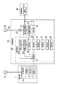
- FIG. 1 is a block diagram showing a first embodiment.
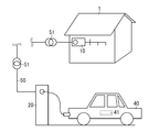
- FIG. 1 is a schematic configuration view of a first embodiment.
- FIG. 7 is an operation explanatory view of the first embodiment.
- FIG. 7 is an operation explanatory view of the first embodiment.
- FIG. 7 is a block diagram showing a second embodiment.
- the power supply system described in the following embodiment includes a metering device 10, a discharge device 20, and a control device 30, as shown in FIG.
- the measuring device 10 measures the amount of power received by the customer 1 from the power grid 51.
- the discharge device 20 supplies the power of the running battery 41 mounted on the electric vehicle 40 to the power wiring 50.
- Control device 30 controls discharge device 20 to adjust the amount of power supplied from battery 41 to power wiring 50.
- the control device 30 includes a communication unit 31 and an adjustment unit 32.
- the communication unit 31 acquires information related to the amount of power measured by the weighing device 10 by communication with the weighing device 10.
- the adjustment unit 32 supplies power from the battery 41 to the power wiring 50 such that the amount of power supplied from the battery 41 to the power wiring 50 corresponds to at least a portion of the power measured by the weighing device 10. Adjust the amount of power.
- the control device 30 acquires, from the weighing device 10, information on the amount of power received by the customer 1 from the power grid 51. Furthermore, the control device 30 causes the amount of power supplied from the driving battery 41 mounted on the electric vehicle 40 to the power wiring 50 to be equal to at least a part of the amount of power measured by the measuring device 10. Adjust to Therefore, even when electric powered vehicle 40 is separated from customer 1, the electric power of battery 41 mounted on electric powered vehicle 40 can be discharged to electric power wiring 50 so as to meet the amount of electric power used by customer 1. become. As a result, the electric power of the battery 41 mounted on the electric vehicle 40 is allocated to at least a part of the electric power received by the customer 1 from the electric power system 51. Therefore, the power supply system has an advantage of contributing to stabilization of the voltage and frequency of the power system 51 while hardly disturbing the equilibrium state between the supply and demand of power in the power system 51.
- the discharge device 20 is disposed at a point away from the customer 1, be electrically connected to the power system 51 via the power wiring 50, and be electrically connected to the battery 41. .
- the electric load of the customer 1 can not be changed to the electric vehicle 40. It is equivalent to supplying power from the battery 41 of
- the control device 30 preferably further includes a storage unit 33, an acquisition unit 34, and a collation unit 35.
- the storage unit 33 stores the first identification information identifying the customer 1 and the second identification information identifying the electric vehicle 40 in association with each other.
- Acquisition unit 34 acquires the second identification information from electrically powered vehicle 40 when electrically powered vehicle 40 is connected to discharge device 20.
- the collation unit 35 collates the second identification information acquired by the acquisition unit 34 with the storage unit 33 to identify the customer 1 having the first identification information corresponding to the second identification information.
- the adjustment unit 32 adjusts the amount of power supplied from the battery 41 to the power wiring 50 so that it corresponds to at least a portion of the amount of power received by the customer 1 identified by the collation unit 35. It is desirable to do.
- Control device 30 further includes a first control device 30A including storage unit 33, acquisition unit 34, and collation unit 35, and a second control device 30B provided to adjustment unit 32 and attached to discharge device 20. Is desirable.
- the acquisition unit 34 preferably has a function of acquiring identification information of the electronic toll collection system, and the identification information of the electronic toll collection system is preferably used as the second identification information. Further, it is desirable that the adjustment unit 32 adjust the amount of power supplied from the battery 41 to the power wiring 50 to be equal to the amount of power measured by the measuring device 10 in a predetermined period.
- the control device 30 preferably includes a first arithmetic unit 361 and a second arithmetic unit 362.
- the first calculation unit 361 calculates a power difference corresponding to a difference between the amount of power supplied from the battery 41 to the power wiring 50 and the amount of power measured by the measuring device 10 in a predetermined period.
- the second calculation unit 362 reflects the power difference calculated by the first calculation unit 361 in the electricity charge.
- the control device 30 preferably further includes a limiting unit 37 that limits at least one of the change rate of the power supplied from the electric vehicle 40 to the power wiring 50 and the peak value.
- Control device 30 further includes setting unit 38 for setting the lower limit value of remaining capacity of battery 41, and management unit 39 for stopping the supply of power from battery 41 to power wiring 50 when the remaining capacity reaches the lower limit value. It is desirable to have further.
- the setting unit 38 when given information on the distance the electric vehicle 40 is to travel, calculates the remaining capacity of the battery 41 necessary to travel the distance, and the lower limit based on the calculated remaining capacity of the battery 41. It is desirable to have the ability to set the value.
- the discharge device 20 is preferably used in the above-described power supply system, and preferably includes the adjustment unit 32.
- a customer (facility) 1 is a house (a detached house or a dwelling unit of an apartment house)
- an office in a building, a tenant, or the like may be the customer 1.
- the user (resident) of the customer 1 holds the electric vehicle 40.
- the technology described below can be applied by regarding the entire apartment house or office building as the customer 1. .
- the electric vehicle 40 may be an electric vehicle, a plug-in hybrid vehicle, a fuel cell vehicle, an electric two-wheel vehicle, or the like as long as the battery 41 is used as an energy source for traveling. Therefore, the running battery 41 mounted on the electric vehicle 40 may be a fuel cell mounted on a fuel cell vehicle, as well as a storage battery such as an electric vehicle or a plug-in hybrid vehicle. Below, the case where the electric vehicle 40 is an electric vehicle or a plug-in hybrid vehicle and the battery 41 is a storage battery will be described.
- the electric vehicle 40 is utilized by daytime, and the utilization form that charge of the battery 41 (storage battery) is performed at night is made into an example, and is demonstrated.
- the battery 41 may be charged with the electric power generated by the solar power generation device before using the electric powered vehicle 40.
- a use form for example, a use form in which the battery 41 is charged in the morning and a use form using the electric vehicle 40 in the afternoon, or a use form in which the battery 41 is charged in the previous day and the electric vehicle 40 is used on the day Is considered.
- the electric power (area D1) at night (0:00 to 6:00) is used to charge the battery 41 (storage battery).
- the vertical axis in FIG. 3 represents power.
- the user goes out using the electric vehicle 40, and connects the electric vehicle 40 to the discharge device 20 from 12:00 to 16:30, so that power wiring from the battery 41 is performed. It is possible to supply 50 power.
- the power received by the customer 1 is transitioning as in the region D2.
- the power discharged from the battery 41 follows the power received by the customer 1, and the power received by the customer 1 in the region D2 and the power wiring 50 are supplied from the discharge device 20.
- the power wiring 50 is an outdoor power wiring that does not belong to the customer 1 (that is, the power system 51), but may be an indoor power wiring connected to the power system 51.
- the power of the battery 41 mounted on the electric vehicle 40 held by the user of the customer 1 can be supplied to the indoor power wiring 50 of another customer 1.
- the electric power received from the electric power system 51 is reduced, so the electric power required for the electric power system 51 is substantially reduced.
- the electric power is supplied from the battery 41 of the electric vehicle 40 to the customer 1, and the customer 1 It is possible to reduce the power received. That is, the demand for the power system 51 is substantially reduced, which contributes to the stabilization of the voltage and frequency of the power system 51.
- Control device 30 can adopt a configuration attached to discharge device 20.
- the control device 30 is configured of a first control device 30A that manages the customer 1 and the electric vehicle 40, and a second control device 30B that controls the operation of the discharge device 20. It may be done.
- the first control device 30A is provided with a communication device (for example, a server) 60 capable of communicating with the weighing device 10 and the discharging device 20.
- the second control device 30B is attached to the discharge device 20.
- each discharge device 20 includes the control device 30
- information on the customer 1 and the electric vehicle 40 can be collectively managed by the first control device 30A, and personal information of this type is not dispersed. Management of personal information is easy. Further, since the second control device 30B is attached to the discharge device 20, the supply of power from the battery 41 to the power wiring 50 can be controlled in real time without delay.
- the aggregator may perform high-voltage collective power reception and distribute power to each customer 1.
- the measuring device 10 may be configured to measure the amount of power for which the aggregator has performed high voltage batch power reception. This aggregator may double as a service provider, which will be described later.
- Discharge device 20 is an input to which at least one of first identification information, which is identification information for identifying customer 1, and second identification information, which is identification information for identifying electrically powered vehicle 40, is input.
- a device (not shown) may be provided. That is, the first identification information is information provided to correspond to each of the plurality of customers 1 in one-to-one correspondence, and is information represented by, for example, a number sequence or a character string.
- the second identification information is information provided to correspond to each of the plurality of electric vehicles 40 in one-to-one correspondence, and is, for example, information represented by a number sequence or a character string.
- the input device is selected from a configuration that performs key input such as a ten key, a configuration that reads a magnetic card or an IC card, and a configuration that reads an IC chip built in a communication device such as a mobile telephone.
- the input device only needs to be able to input the second identification information, but if the first identification information can be input, the control device 30 confirms the combination of the first identification information and the second identification information.
- the communication with the required weighing device 10 is highly reliable.
- the measuring device 10 which measures the electric energy which the customer 1 received from the electric power grid
- the weighing apparatus 10 supplies the amount of power supplied from the power system 51 to the customer 1 and used by the customer 1, that is, the amount of power consumed by the electric load (equipment and equipment) provided to the customer 1
- the measuring apparatus 10 preferably has a configuration in which a power meter installed in the customer 1 is used as the measuring unit 11 in order to charge the user (resident) of the customer 1 by the electric power company.
- the measuring unit 11 acquires information on the amount of electric power from the electric power meter, and performs processing such as integration on the information acquired from the electric power meter as necessary.
- the measuring unit 11 may be configured to measure the amount of power received from the power system 51 on the primary side of a distribution board (not shown).
- the measuring unit 11 acquire the amount of power every unit time (selected from 30 seconds, 1 minute, 5 minutes, 10 minutes, 15 minutes, 30 minutes, etc.). Also, the measuring unit 11 measures the amount of power per relatively short unit time (30 seconds, 1 minute, etc.) as instantaneous power, and for each relatively long unit time (10 minutes, 15 minutes, 30 minutes, etc.), The transition of the instantaneous power and the integrated power amount in the corresponding unit time may be determined. That is, the amount of power measured by the weighing device 10 includes a relatively short amount of power per unit time (instant power) and a relatively long integrated amount of power per unit time.
- the weighing device 10 includes a holding unit 12 that holds identification information (first identification information) assigned to the customer 1.
- the first identification information is given in advance so as to be different for each customer 1.
- the management of the first identification information is performed by the electric utility who manages the control device 30.
- This type of electricity supplier includes general producers such as electricity producers, as well as specified size electricity producers (PPS: Power Producer and Supplier), specified electricity producers, independent power producers (IPP: Independent Power Producer). And so on. Also, an aggregator may manage the control device 30.
- the weighing device 10 includes a communication interface unit (hereinafter referred to as “communication I / F”) 13.
- the communication I / F 13 has a function of communicating with the control device 30 through a telecommunication line (not shown) such as the Internet, and when requested by the control device 30, information on the amount of power measured by the weighing device 10 , And the first identification information to the control device 30.
- discharge device 20 is disposed at a facility where electric powered vehicle 40 is parked.
- Facilities of this type are, for example, a parking lot attached to some kind of facility such as a commercial facility, a hospital, a hotel, an airport, a sports facility, a public parking lot, a coin parking, a parking lot of an apartment house, etc.
- Discharge device 20 includes a cable (not shown) and a connector (not shown) electrically connected to a battery 41 (here, a storage battery) mounted on electrically powered vehicle 40.
- the connector is configured to be attachable to and detachable from an inlet provided to the electric vehicle 40.
- the discharge device 20 is connected to the power wiring 50 (here, the power system 51).
- the charge / discharge device is configured by adding the function of the discharge device 20 described in the present embodiment to the charging device that charges the battery 41. May be
- Discharge device 20 includes power converter 21 for converting direct current power of battery 41 mounted on electrically powered vehicle 40 into AC power which can be supplied to power wiring 50, and power converter 21 according to contents instructed from control device 30. And a discharge control unit 22 that controls the discharge.
- the control device 30 is attached to the discharge device 20. However, the control device 30 does not have to share the case with the discharge device 20, and may be housed in separate cases. In addition, a plurality of discharge devices 20 may be controlled by one control device 30.
- the discharge device 20 includes a current transformer 23 at the outlet from the power converter 21 to the power wiring 50 in order to monitor the power supplied from the power converter 21 to the power wiring 50.
- the current transformer 23 has a configuration in which a detection coil is wound around an annular core such as a toroidal core, and is disposed such that an output corresponding to the current output from the power converter 21 to the power wiring 50 can be obtained from the coil. Be done.
- the output of the current transformer 23 is given to the controller 30 and used to control the power output from the power converter 21.
- the control device 30 includes a communication unit 31 that communicates with the weighing device 10.
- the communication unit 31 acquires information on the amount of power measured by the weighing device 10 and the first identification information held by the weighing device 10 by communicating with the weighing device 10. That is, the communication unit 31 acquires information on the amount of power received by the customer 1 from the power grid 51 and the first identification information associated with the customer 1.
- Control device 30 also includes adjustment unit 32 that adjusts the amount of power supplied from battery 41 to power wiring 50. In other words, the adjustment unit 32 adjusts the amount of power supplied from the battery 41 to the power system 51 via the power wiring 50.
- the adjustment unit 32 instructs the discharge control unit 22 to adjust the amount of power supplied from the battery 41 to the power wiring 50 according to the information on the amount of power acquired by the communication unit 31 from the weighing device 10.
- Control device 30 includes an acquisition unit 34 for acquiring identification information (second identification information) of electrically powered vehicle 40 in a state where discharge device 20 is electrically connected to battery 41 of electrically powered vehicle 40.
- the second identification information is provided to be different for each of the electric vehicles 40.
- the second identification information can use information registered in an ECU (Electronic Control Unit) or the like mounted on the electric vehicle 40.
- ETC Electronic Toll Collection System
- ETC Electronic Toll Collection System
- this identification information may be used as the second identification information.
- ETC here is a system that automatically settles charges when using an expressway, for example, and performs wireless communication between a communication device installed on the road and an ETC in-vehicle device mounted on the electric vehicle 40. Is a system that settles the fee.
- the acquisition unit 34 of the control device 30 needs a function of acquiring identification information of ETC.
- Control device 30 has storage part 33 which matches and memorizes the 1st discernment information and the 2nd discernment information.
- the second identification information acquired by the acquisition unit 34 from the electric vehicle 40 is a first identification of the weighing device 10 installed in the customer 1 of the same user as the user who holds the electric vehicle 40. It is registered in advance in association with the information.
- the collation unit 35 provided in the control device 30 collates the second identification information acquired from the electric vehicle 40 with the storage unit 33, and extracts first identification information corresponding to the second identification information. That is, of the plurality of pieces of second identification information stored in storage portion 33, collation portion 35 corresponds to the first identification information corresponding to the second identification information acquired from electric powered vehicle 40. Extract identification information. Therefore, when the second identification information is acquired from the electrically powered vehicle 40, the collation unit 35 collates the storage unit 33, whereby the customer 1 of the same user as the electrically powered vehicle 40 is identified.
- the control device 30 specifies the consumer 1 of the same user as the electric vehicle 40 by acquiring the second identification information from the electric vehicle 40. Since the communication unit 31 of the control device 30 acquires information on the amount of power received from the power grid 51 in the customer 1, the adjustment unit 32 determines the amount of power supplied from the discharge device 20 to the power wiring 50. Adjust according to the amount of power related to the customer 1.
- adjustment unit 32 corresponds to at least a part of the amount of power measured by weighing device 10 of customer 1 who is the same user as electric powered vehicle 40, with the amount of power supplied from discharge device 20 to power wiring 50. Adjust to the amount of power. That is, the amount of power supplied from the discharge device 20 to the power wiring 50 is adjusted with the goal of equalizing the amount of power measured by the weighing device 10 of the customer 1.
- the adjustment unit 32 matches the instantaneous value of the power supplied from the discharge device 20 to the power wiring 50 with the instantaneous value of the power received by the customer 1.
- the instantaneous value of the power actually means the amount of power in a short time of about 30 seconds or 1 minute.
- the adjustment unit 32 instructs the discharge control unit 22 such that the amount of power supplied from the discharge device 20 to the power wiring 50 matches the amount of power received by the customer 1 in a predetermined period.
- the predetermined period is selected from, for example, 15 minutes, 30 minutes, and 1 hour. It is also possible to equalize in units of one day, one week, one month, etc., but since the electric vehicle 40 moves, the amount of power used by the customer 1 and the amount of power discharged from the battery 41 are stored. There is a need to.
- the device for storing the information of the amount of power is provided in the customer 1 who holds the electric vehicle 40 or in the communication device 60 (see FIG. 5) described later.
- the present embodiment adopts a configuration in which the amount of power supplied by the discharge device 20 to the power wiring 50 every 30 minutes is equal to the amount of power supplied by the customer 1 every 30 minutes.
- the information on the amount of power acquired by the adjustment unit 32 from the weighing device 10 is information on the amount of power in the past 30 minutes. Therefore, the adjustment unit 32 causes the discharge control unit 22 to equalize the amount of power for 30 minutes after acquiring information on the amount of power from the weighing device 10 with the amount of power received by the customer 1 in the past 30 minutes. Control the operation of
- control device 30 When control device 30 is notified that electric powered vehicle 40 is connected to discharge device 20 (P1), control device 30 acquires the second identification information (P2), and the second corresponding to the second identification information is obtained. The identification information of 1 is extracted (P3). Next, the control device 30 requests information on the amount of power received by the customer 1 to the weighing device 10 of the customer 1 specified according to the first identification information (P4), and acquires information on the amount of power Do (P5).
- the control device 30 determines the amount of power to be discharged according to the information on the amount of power acquired from the weighing device 10 (P6), and instructs the discharge control unit 22 to discharge the power from the battery 41 (P7). In addition, before determining the electric power discharged from the battery 41, it is necessary to acquire the information regarding the remaining capacity of the battery 41 from the electric vehicle 40 (or the discharge device 20).
- control device 30 acquires information on the amount of power supplied from the discharge device 20 to the power wiring 50 (P8), and again acquires the amount of power from the weighing device 10 (P9, P10). Thereafter, the same processing is repeated until the electric vehicle 40 is detached from the discharge device 20.
- the following processing may be performed to equalize the amount of power supplied from the discharge device 20 to the power wiring 50 with the amount of power received by the customer 1 in a predetermined period (30 minutes in the above example). That is, the control device 30 acquires the information of the amount of power from the measuring device 10 every fixed time (one minute, 5 minutes, 10 minutes) shorter than the predetermined time, and the moving average value of the power amount every fixed time It may be used to equalize the amount of power.
- the control device 30 obtains the amount of power from the weighing device 10 every 30 minutes, the adjustment of the amount of power supplied from the discharge device 20 to the power wiring 50 is delayed by a time of 30 minutes. The time delay is greatly reduced. Further, this process suppresses the fluctuation of the power supplied from the discharge device 20 to the power wiring 50.
- the amount of power supplied from the discharge device 20 to the power wiring 50 is adjusted based on the amount of power received by the customer 1. Therefore, focusing only on the relationship between the demand and supply of power, it is equivalent to supplying power from the battery 41 of the electric vehicle 40 to the electrical load of the customer 1. That is, since the electric energy corresponding to the electric energy received by the customer 1 is supplied from the discharge device 20 to the electric power line 50, although the time delay occurs, the electric energy received from the electric power system 51 and the electric power system 51 are supplied Offset with the amount of electricity consumed.
- the user of the customer 1 charges the battery 41 using inexpensive electric power such as nighttime electric power or electric power generated by the solar power generation facility for the electric vehicle 40, the electric power of the battery 41 is transmitted to the electric power wiring 50. It is possible to widen the difference with the profit obtained by supplying. In other words, the user of the customer 1 substantially benefits by reducing the cost for earning.
- the service provider who manages the reception of the electric power makes a connection between the electric power supplier supplying the electric power and the user, the user supplies electric power from the electric vehicle 40 to the electric load at the home (customer 1). It is possible to collect electricity charges from the user as if it were the case. That is, the service provider manages the amount of power received by the customer 1 from the power system 51 and the amount of power supplied from the electric vehicle 40 owned by the user of the customer 1 to the power wiring 50, both If the amount is equal, the electricity charge is offset for the user of the customer 1. In addition, the service provider pays compensation for the amount of power used by the customer 1 to the power supplier supplying the power, and receives compensation for the amount of power supplied from the discharge device 20 to the power wiring 50. .
- the service provider may be an electric provider that supplies power to the customer 1 through the power system 51.
- control device 30 preferably includes a first calculation unit 361 that manages the amount of power and a second calculation unit 362 that manages the electricity charge. .
- the first calculation unit 361 calculates a power difference corresponding to a difference between the amount of power supplied from the battery 41 to the power wiring 50 and the amount of power measured by the measuring device 10 in a predetermined period. That is, the first calculation unit 361 determines the power for a predetermined period from the power obtained by the communication unit 31 from the weighing device 10 and the power obtained based on the output of the current transformer 23 provided in the discharge device 20. The power difference corresponding to the difference of the quantities is calculated. In the example described above, since the amount of power received by the customer 1 and the amount of power supplied to the power wiring 50 by the discharge device 20 are equal, the power difference is zero. The case where the power difference is not zero will be described later.
- the predetermined period may be the same as the above-described predetermined period, but since the electricity charge is determined by the amount of power in this predetermined period, the period for charging the electricity charge (for example, one month) may be used as a unit.
- the second calculation unit 362 determines the electricity charge to be charged to the user of the customer 1 in consideration of the power difference calculated by the first calculation unit 361. As described above, the time for supplying power from the discharge device 20 is delayed with respect to the time for which the customer 1 receives power. Therefore, when the time zone in which power is supplied from discharge device 20 and the time zone in which customer 1 receives power are different time zones of electricity rates, the method of calculating electricity rates required of customer 1 will be described. It is necessary to set rules separately.
- the service provider will supply power to the power supplier that supplies power via the power wiring 50, so earning revenue from selling electricity. Is possible.
- the service provider earns a profit for supplying the power from the electric vehicle 40 to the power wiring 50 because the revenue from the power sale is more than the cost from the power purchase. Therefore, as described above, the service provider can provide the user of customer 1 with the amount of power supplied from electric powered vehicle 40 to power wiring 50 in addition to the electricity charge collected from the user of customer 1. Appropriate benefits may be given.
- the amount of power that can be supplied to the power wiring 50 by the discharge of the battery 41 is limited according to the distance the electric vehicle 40 is to travel. receive.
- the amount of power that can be supplied to the power wiring 50 is only the surplus that leaves the remaining capacity necessary for traveling, if the amount of power received by the customer 1 is larger than this surplus, the customer 1 It can not be equal to the amount of received power.
- the control device 30 preferably includes the setting unit 38 in order to set the lower limit value of the remaining capacity of the battery 41.
- a management unit 39 is also provided which stops the supply of power from the battery 41 to the power wiring 50 when the remaining capacity of the battery 41 reaches the lower limit value set in the setting unit 38.
- the setting of the lower limit value by the setting unit 38 can be performed by the user using a man-machine interface (input device, display device).
- the setting unit 38 determines the traveling planned distance.
- the lower limit value of the remaining capacity of the battery 41 is calculated based on That is, the setting unit 38 has a function of calculating the remaining capacity of the battery 41 necessary to travel the distance, setting a lower limit value by giving a margin to the calculated remaining capacity.
- the setting unit 38 automatically sets the lower limit value of the remaining capacity of the battery 41, the user receives power at the customer 1 without burden of managing the remaining capacity of the battery 41. It is possible to supply power corresponding to the amount of power from the battery 41 to the power wiring 50.
- the control device 30 includes a limiting unit 37 that limits at least one of the change rate and the peak value for the power instructed from the adjusting unit 32 to the discharge control unit 22.
- the change rate indicates the change rate per unit time with respect to the magnitude of the power.
- the amount of power supplied to the power wiring 50 through the discharge device 20 is equal to the amount of power received by the customer 1
- the amount of power extracted from the battery 41 mounted on the electric vehicle 40 is adjusted
- the first embodiment exemplifies the configuration in which the control device 30 is attached to the discharge device 20, but in the present embodiment, as shown in FIG. 5, the control device 30 includes the first control device 30A and the second control device 30B. And the first control device 30A is provided separately from the discharge device 20.
- the first control device 30A includes a storage unit 33, an acquisition unit 34, and a check unit 35, and communicates with the discharge device 20.
- the second control device 30 ⁇ / b> B includes the adjustment unit 32 and is attached to the discharge device 20.
- the first control device 30A is provided in a communication device 60 such as an independent server or a distributed server configured as a cloud computing system. In the figure, the configuration regarding communication between the first control device 30A and the second control device 30B is omitted.
- the subsequent processing is the same as that of the first embodiment, and acquires information on the amount of power for a predetermined period from the corresponding weighing device 10 through the communication unit 31, and notifies the adjustment unit 32 of the information on the acquired amount of power.
- the adjustment unit 32 that receives the information on the amount of power received by the customer 1 from the first control device 30A instructs the discharge control unit 22 to adjust the amount of power supplied from the battery 41 to the power wiring 50. .
- the configuration example described above assumes that the customer 1 and the discharge device 20 are managed by the same electric utility (or service provider), but an electric business that manages the customer 1 and the discharge device 20 If the service provider (or service provider) is different, perform the following processing.
- the communication devices 60 are configured to be able to communicate with one another.
- the other communication device 60 includes the communication device 60 managed by an electric company (or a service company) different from the electric company (or the service company) managing the discharge device 20.
- collation unit 35 collates storage unit 33 with the second identification information.
- the second identification information is not registered in the storage unit 33, the second identification information is notified to the other communication device 60, and it is inquired whether it is registered in the other communication device 60 or not. .
- the communication device 60 when the second identification information is registered in the storage unit 33, the communication device 60 that communicates with the discharge device 20 performs another communication on the information related to the amount of power measured by the corresponding weighing device 10. Acquired from the device 60.
- the subsequent processing is the same as the above-described processing, and power is supplied from the discharge device 20 to the power wiring 50 in accordance with the amount of power received by the customer 1.
- the power difference is calculated in the communication device 60 that manages the discharge device 20 and notified to the communication device 60 that manages the customer 1. Therefore, the electricity rate follows the rate system of the electricity supplier (or service provider) with which the user of customer 1 has a contract.
- the communication device 60 that manages the charging device acquires the amount of power that has charged the battery 41 (storage battery), and contracts this amount of power with the user of the electric vehicle 40 (which is also the user of the customer 1).
- the communication device 60 of the electric power company (or service provider) is notified. Therefore, it becomes possible to charge the user of the customer 1 for the electricity charge for the amount of power charging the battery 41.
- the electricity rate in this case also follows the rate system of the electricity supplier (or service provider) with which the user of the customer 1 has a contract.
- Other configurations and operations are the same as in the first embodiment.
Landscapes
- Engineering & Computer Science (AREA)
- Power Engineering (AREA)
- Transportation (AREA)
- Mechanical Engineering (AREA)
- Life Sciences & Earth Sciences (AREA)
- Sustainable Development (AREA)
- Sustainable Energy (AREA)
- Charge And Discharge Circuits For Batteries Or The Like (AREA)
- Electric Propulsion And Braking For Vehicles (AREA)
- Supply And Distribution Of Alternating Current (AREA)
- Remote Monitoring And Control Of Power-Distribution Networks (AREA)
Abstract
電動車両が需要家から離れている場合でも、需要家で使用した電力量に見合うように、電動車両に搭載された電池の電力を電力配線に放電することを可能にする。計量装置(10)は、需要家(1)が電力系統(51)から受電した電力量を計量する。放電装置(20)は、電動車両(40)に搭載された走行用の電池(41)の電力を電力配線(50)に供給する。制御装置(30)は、電池(41)から電力配線(50)に供給する電力量を調整するように放電装置(20)を制御する。制御装置(30)の通信部(31)は、計量装置(10)で計量された電力量に関する情報を計量装置(10)との通信により取得する。制御装置(30)の調整部(32)は、電池(41)から電力配線(50)に供給する電力量が、計量装置(10)で計量された電力量の少なくとも一部に相当する電力量になるように調整する。
Description
本発明は、一般に電力供給システム、放電装置に関し、より詳細には、電動車両に搭載された走行用の電池から電力配線に電力を供給する電力供給システム、この電力供給システムに用いる放電装置に関する。
近年、電動車両が普及し始めている。電動車両は、走行用に比較的容量の大きい電池を搭載している。一方、統計によれば、自家用車の1日当たりの走行距離の平均値は30km未満である。したがって、電動車両に搭載されている電池の種類にもよるが、1日当たりの走行距離の平均値に対して、電池の容量は十分な余裕を有していることが多い。
そのため、需要家において電動車両の電力を電気負荷で利用できるように、需要家における配線網に電動車両の電力を供給可能にする技術が提案されている(たとえば、文献1:JP2008-54439A、文献2:JP2013-27214A参照)。文献1には、蓄電装置を搭載した電動車両が住宅に電気的に接続され、電動車両が商用電源を生成して住宅に供給する技術が記載されている。また、文献2には、建物に配線された交流電力線に充電スタンドが接続され、車載蓄電装置が蓄電している電力を交流電力線に放電する技術が記載されている。
文献1、2に記載された技術によれば、住宅への供給電力および住宅での消費電力に応じて電動車両の充放電を制御したり、予測期間における消費量および発電量の予測データに基づいて充放電スケジュールを定めたりすることが可能である。
一方、電動車両に搭載された蓄電池の電力を住宅(需要家)で利用しようとすれば、電動車両が需要家の電力配線に接続されていなければならない。つまり、電動車両が需要家から離れているときには、電動車両に搭載された蓄電池の電力は需要家において利用できない。
本発明は、電動車両が需要家から離れている場合でも電動車両に搭載された電池の電力を需要家において利用した電力に充当可能な電力供給システム、およびこの電力供給システムに用いる放電装置を提供することを目的とする。
本発明に係る電力供給システムは、需要家が電力系統から受電した電力量を計量する計量装置と、電動車両に搭載された走行用の電池の電力を電力配線に供給する放電装置と、前記電池から前記電力配線に供給する電力量を調整するように前記放電装置を制御する制御装置とを備え、前記制御装置は、前記計量装置で計量された電力量に関する情報を前記計量装置との通信により取得する通信部と、前記電池から前記電力配線に供給する電力量が、前記計量装置で計量された電力量の少なくとも一部に相当する電力量になるように、前記電池から前記電力配線に供給する電力量を調整する調整部とを備えることを特徴とする。
本発明に係る放電装置は、上述した電力供給システムに用いられ、前記調整部を備えることを特徴とする。
(概要)
以下の実施形態で説明する電力供給システムは、図1に示すように、計量装置10と放電装置20と制御装置30とを備える。計量装置10は、需要家1が電力系統51から受電した電力量を計量する。放電装置20は、電動車両40に搭載された走行用の電池41の電力を電力配線50に供給する。制御装置30は、電池41から電力配線50に供給する電力量を調整するように放電装置20を制御する。制御装置30は、通信部31と調整部32とを備える。通信部31は、計量装置10で計量された電力量に関する情報を計量装置10との通信により取得する。調整部32は、電池41から電力配線50に供給する電力量が、計量装置10で計量された電力量の少なくとも一部に相当する電力量になるように、電池41から電力配線50に供給する電力量を調整する。
以下の実施形態で説明する電力供給システムは、図1に示すように、計量装置10と放電装置20と制御装置30とを備える。計量装置10は、需要家1が電力系統51から受電した電力量を計量する。放電装置20は、電動車両40に搭載された走行用の電池41の電力を電力配線50に供給する。制御装置30は、電池41から電力配線50に供給する電力量を調整するように放電装置20を制御する。制御装置30は、通信部31と調整部32とを備える。通信部31は、計量装置10で計量された電力量に関する情報を計量装置10との通信により取得する。調整部32は、電池41から電力配線50に供給する電力量が、計量装置10で計量された電力量の少なくとも一部に相当する電力量になるように、電池41から電力配線50に供給する電力量を調整する。
この構成によれば、制御装置30は、需要家1が電力系統51から受電した電力量に関する情報を計量装置10から取得する。さらに、制御装置30は、電動車両40に搭載された走行用の電池41から電力配線50に供給する電力量を、計量装置10が計量した電力量の少なくとも一部に相当する電力量になるように調整する。したがって、電動車両40が需要家1から離れている場合でも、需要家1で使用した電力量に見合うように、電動車両40に搭載された電池41の電力を電力配線50に放電することが可能になる。その結果、電動車両40に搭載された電池41の電力は、需要家1が電力系統51から受電した電力の少なくとも一部に充当される。したがって、電力供給システムは、電力系統51における電力の需要と供給との平衡状態をほとんど乱すことがなく、電力系統51の電圧および周波数の安定化に寄与するという利点を有する。
ここで、放電装置20は、需要家1から離れた地点に配置されており、電力配線50を介して電力系統51と電気的に接続され、かつ電池41と電気的に接続されることが望ましい。この構成によれば、互いに離れた2地点に存在する需要家1と電動車両40との間においても、電力の需要と供給との関係にのみ着目すると、需要家1の電気負荷に電動車両40の電池41から電力を供給していることと等価になる。
制御装置30は、記憶部33と取得部34と照合部35とをさらに備えることが望ましい。記憶部33は、需要家1を識別する第1の識別情報と電動車両40を識別する第2の識別情報とを対応付けて記憶する。取得部34は、電動車両40が放電装置20に接続されると第2の識別情報を電動車両40から取得する。照合部35は、取得部34が取得した第2の識別情報を記憶部33に照合することにより、当該第2の識別情報に対応した第1の識別情報を有する需要家1を特定する。この場合、調整部32は、電池41から電力配線50に供給する電力量が、照合部35で特定された需要家1が受電した電力量の少なくとも一部に相当する電力量になるように調整することが望ましい。
制御装置30は、記憶部33と取得部34と照合部35とを備える第1の制御装置30Aと、調整部32を備え放電装置20に付設される第2の制御装置30Bとをさらに備えることが望ましい。
取得部34は、電子料金収受システムの識別情報を取得する機能を有し、この電子料金収受システムの識別情報が前記第2の識別情報として用いられることが望ましい。また、調整部32は、所定期間において、電池41から電力配線50に供給する電力量を、計量装置10で計量された電力量と等量にすることを目標として調整することが望ましい。
ところで、制御装置30は、図5のように、第1の演算部361と第2の演算部362とを備えることが望ましい。第1の演算部361は、所定期間において、電池41から電力配線50に供給した電力量と計量装置10で計量された電力量との差分に相当する電力差分を算出する。第2の演算部362は、第1の演算部361が算出した電力差分を電気料金に反映させる。
制御装置30は、電動車両40から電力配線50に供給する電力の変化率とピーク値との少なくとも一方を制限する制限部37をさらに備えることが望ましい。また、制御装置30は、電池41の残容量に関する下限値を設定する設定部38と、残容量が下限値に達すると電池41から電力配線50への電力の供給を停止する管理部39とをさらに備えることが望ましい。設定部38は、電動車両40が走行する予定の距離に関する情報が与えられると、当該距離を走行するのに必要な電池41の残容量を算出し、算出した電池41の残容量に基づいて下限値を設定する機能を有することが望ましい。
また、放電装置20は、上述した電力供給システムに用いられ、調整部32を備えることが望ましい。
以下では、需要家(facility)1が住宅(戸建て住宅、あるいは集合住宅の住戸)である場合を例として説明するが、建物内のオフィス、テナントなどが需要家1であってもよい。また、以下では、需要家1のユーザ(住人)が電動車両40を保有している場合を想定して説明する。ただし、集合住宅やオフィスビルなどにおいて、複数のユーザが電動車両40を共有している場合、集合住宅やオフィスビルの全体を需要家1とみなすことにより、以下に説明する技術を適用可能である。
電動車両40は、電気自動車、プラグインハイブリッド車、燃料電池車、電動二輪車など、走行用のエネルギー源として電池41が用いられる車両であればよい。したがって、電動車両40に搭載された走行用の電池41は、電気自動車やプラグインハイブリッド車のように蓄電池である場合のほか、燃料電池車に搭載された燃料電池であってもよい。以下では、電動車両40が電気自動車、あるいはプラグインハイブリッド車であって、電池41が蓄電池である場合について説明する。
さらに、以下では、電動車両40が日中に利用され、夜間に電池41(蓄電池)の充電が行われるという利用形態を例にして説明する。需要家1が太陽光発電装置を備える場合には、電動車両40を利用する前に、太陽光発電装置で発電した電力で電池41の充電を行うようにしてもよい。このような利用形態としては、たとえば、午前中に電池41を充電し、午後に電動車両40を利用する利用形態、あるいは前日に電池41を充電し、当日に電動車両40を利用する利用形態などが考えられる。
図3に示す例では、夜間(0:00~6:00)の電力(領域D1)を用いて電池41(蓄電池)を充電している。図3の縦軸は電力を表す。また、日中(7:00~18:00)に電動車両40を利用して外出し、12:00~16:30に電動車両40を放電装置20に接続することにより、電池41から電力配線50への電力の供給が可能になっている。この時間帯(12:00~16:30)において、需要家1が受電している電力は、領域D2のように推移している。そして、図示例では、電池41から放電する電力が需要家1が受電している電力に追従しており、領域D2において需要家1が受電する電力と、放電装置20から電力配線50に供給する電力とが一致している。
電力配線50は、需要家1に属していない屋外の電力配線(つまり、電力系統51)である場合を例にするが、電力系統51に接続された屋内の電力配線であってもよい。たとえば、需要家1のユーザが保有する電動車両40に搭載した電池41の電力を、他の需要家1の屋内の電力配線50に供給することも可能である。この場合、電動車両40の電池41から電力が供給された需要家1では、電力系統51から受電する電力が低減するから、実質的に電力系統51に要求される電力を低減させたことになる。
上述した構成を採用することにより、電力系統51に対する需要が増加して電力が逼迫する可能性がある場合には、電動車両40の電池41から需要家1に電力を供給し、需要家1が受電する電力を低減させることが可能である。すなわち、電力系統51に対する需要を実質的に低減させることになり、電力系統51の電圧および周波数の安定化に寄与する。
制御装置30は、放電装置20に付設される構成を採用可能である。ただし、図5に示すように、制御装置30は、需要家1と電動車両40とを管理する第1の制御装置30Aと、放電装置20の動作を制御する第2の制御装置30Bとで構成されていてもよい。第1の制御装置30Aは、計量装置10および放電装置20との通信が可能である通信装置(たとえば、サーバ)60が備える。また、第2の制御装置30Bは、放電装置20に付設される。
この構成を個々の放電装置20が制御装置30を備える構成と比較すると、需要家1と電動車両40とに関する情報を第1の制御装置30Aでまとめて管理でき、この種の個人情報が分散しないから、個人情報の管理が容易である。また、第2の制御装置30Bが放電装置20に付設されるから、電池41から電力配線50への電力の供給を遅滞なくリアルタイムに制御できる。
以下では説明しないが、複数の需要家1をまとめるアグリゲータが存在する場合、アグリゲータが高圧一括受電を行って、それぞれの需要家1に電力を分配してもよい。この場合、計量装置10は、アグリゲータが高圧一括受電を行った電力量を計量する構成であってもよい。このアグリゲータは、後述するサービス提供事業者を兼ねていてもよい。
放電装置20は、需要家1を識別するための識別情報である第1の識別情報と、電動車両40を識別するための識別情報である第2の識別情報との少なくとも一方が入力される入力装置(図示せず)を備えていてもよい。つまり、第1の識別情報は複数の需要家1の各々に対して一対一に対応するように付与される情報であって、たとえば数列や文字列によって表される情報である。第2の識別情報は複数の電動車両40の各々に対して一対一に対応するように付与される情報であって、たとえば数列や文字列によって表される情報である。入力装置は、テンキーのようなキー入力を行う構成、磁気カードあるいはICカードを読み取る構成、移動体電話機のような通信機器に内蔵したICチップを読み取る構成などから選択される。入力装置は、一般的には、第2の識別情報のみを入力できればよいが、第1の識別情報を入力できれば、制御装置30により第1の識別情報と第2の識別情報との組み合わせを確認した上で、所要の計量装置10と通信するから信頼性が高くなる。
(実施形態1)
図1、図2に示すように、需要家1には、需要家1が電力系統51から受電した電力量を計量する計量装置10が設置される。言い換えれば、計量装置10は、電力系統51から需要家1に供給され需要家1で使用される電力量、つまり需要家1に設けられた電気負荷(設備および機器)にて消費される電力量を計量する。計量装置10は、電気事業者が需要家1のユーザ(住人)に課金するために需要家1に設置している電力メータを計量部11として用いる構成が望ましい。すなわち、計量部11は電力メータから電力量に関する情報を取得し、電力メータから取得した情報に必要に応じて積算などの加工を施す構成が望ましい。ただし、計量部11は、電力系統51から受電した電力量を分電盤(図示せず)の1次側において計量する構成であってもよい。
図1、図2に示すように、需要家1には、需要家1が電力系統51から受電した電力量を計量する計量装置10が設置される。言い換えれば、計量装置10は、電力系統51から需要家1に供給され需要家1で使用される電力量、つまり需要家1に設けられた電気負荷(設備および機器)にて消費される電力量を計量する。計量装置10は、電気事業者が需要家1のユーザ(住人)に課金するために需要家1に設置している電力メータを計量部11として用いる構成が望ましい。すなわち、計量部11は電力メータから電力量に関する情報を取得し、電力メータから取得した情報に必要に応じて積算などの加工を施す構成が望ましい。ただし、計量部11は、電力系統51から受電した電力量を分電盤(図示せず)の1次側において計量する構成であってもよい。
計量部11は、単位時間(30秒、1分、5分、10分、15分、30分などから選択される)ごとに電力量を取得することが望ましい。また、計量部11は、比較的短い単位時間(30秒、1分など)ごとの電力量を瞬時電力として計量し、比較的長い単位時間(10分、15分、30分など)ごとに、瞬時電力の推移と該当する単位時間における積算電力量とを求めてもよい。つまり、計量装置10で計量される電力量は、比較的短い単位時間ごとの電力量(瞬時電力)と、比較的長い単位時間ごとの積算電力量とを含んでいる。
計量装置10は、需要家1に付与された識別情報(第1の識別情報)を保持する保持部12を備える。第1の識別情報は、需要家1ごとに異なるようにあらかじめ付与される。第1の識別情報の管理は、制御装置30を管理する電気事業者が行う。この種の電気事業者は、電力会社のような一般電気事業者のほか、特定規模電気事業者(PPS:Power Producer and Supplier)、特定電気事業者、独立発電事業者(IPP:Independent Power Producer)などでもよい。また、アグリゲータが制御装置30を管理してもよい。
計量装置10は、通信インターフェイス部(以下、「通信I/F」と記載する)13を備える。通信I/F13は、インターネットのような電気通信回線(図示せず)を通して制御装置30と通信する機能を有し、制御装置30から要求されると、計量装置10が計量した電力量に関する情報と、第1の識別情報とを制御装置30に引き渡す。
一方、放電装置20は、電動車両40を駐車する施設に配置される。この種の施設は、たとえば、商業施設、病院、ホテル、空港、スポーツ施設などの何らかの施設に付設された駐車場、公共駐車場、コインパーキング、集合住宅の駐車場などである。
放電装置20は、電動車両40に搭載された電池41(ここでは、蓄電池)と電気的に接続されるケーブル(図示せず)およびコネクタ(図示せず)を備える。コネクタは、電動車両40に設けられたインレットに対して着脱が可能となるように構成されている。また、放電装置20は、電力配線50(ここでは、電力系統51)に接続されている。本実施形態における放電装置20は、電池41の放電のみを行うが、電池41の充電を行う充電装置に、本実施形態において説明する放電装置20の機能を付加することによって充放電装置を構成してもよい。
放電装置20は、電動車両40に搭載された電池41の直流電力を電力配線50に供給可能な交流電力に変換する電力変換器21と、制御装置30から指示される内容に従って電力変換器21を制御する放電制御部22とを備える。図示例では、制御装置30は、放電装置20に付設されている。ただし、制御装置30は、放電装置20と筐体を共用する必要はなく、それぞれ別の筐体に収納されていてもよい。また、1台の制御装置30で複数台の放電装置20を制御してもよい。
放電装置20は、電力変換器21から電力配線50に供給する電力を監視するために、電力変換器21から電力配線50への出口に電流トランス23を備える。電流トランス23は、トロイダルコアのような環状のコアに検出用のコイルを巻いた構成であり、電力変換器21から電力配線50に出力される電流に応じた出力がコイルから得られるように配置される。電流トランス23の出力は、制御装置30に与えられ、電力変換器21から出力する電力の制御に用いられる。
制御装置30は、計量装置10と通信する通信部31を備える。通信部31は、計量装置10で計量された電力量に関する情報と、計量装置10が保持する第1の識別情報とを、計量装置10と通信することによって取得する。つまり、通信部31は、需要家1が電力系統51から受電した電力量に関する情報と、この需要家1に対応付けられた第1の識別情報とを取得する。また、制御装置30は、電池41から電力配線50に供給する電力量を調整する調整部32を備える。言い換えれば、調整部32は、電池41から電力配線50を介して電力系統51に供給される電力量を調整する。調整部32は、通信部31が計量装置10から取得した電力量に関する情報に応じて、電池41から電力配線50に供給する電力量を調整するように、放電制御部22に指示する。
制御装置30は、放電装置20が電動車両40の電池41と電気的に接続された状態において、電動車両40の識別情報(第2の識別情報)を取得する取得部34を備える。第2の識別情報は、電動車両40ごとに異なるように付与されている。第2の識別情報は、電動車両40に搭載されたECU(Electronic Control Unit:電子制御ユニット)などに登録された情報を用いることが可能である。
また、ETC(Electronic Toll Collection System:電子料金収受システム)の識別情報を流用できる場合には、この識別情報を第2の識別情報に用いてもよい。ここでいうETCは、たとえば高速道路の利用時に自動で料金を精算するシステムであって、道路に設置された通信装置と電動車両40に搭載されたETC車載器との間で無線通信を行うことにより、料金を精算するシステムである。ETCの識別情報を用いる場合、制御装置30の取得部34は、ETCの識別情報を取得する機能が必要である。同様に、CHAdeMO(商標)規格における電動車両40の識別情報を用いることも可能である。
このように、電動車両40に関する第2の識別情報を自動的に取得する構成を採用すれば、第2の識別情報を手動で与える操作が不要であり、電池41から電力配線50への給電を行う際の操作が簡単になる。
制御装置30は、第1の識別情報と第2の識別情報とを対応付けて記憶する記憶部33を有している。記憶部33には、取得部34が電動車両40から取得する第2の識別情報が、当該電動車両40を保有するユーザと同一ユーザの需要家1に設置された計量装置10の第1の識別情報に対応付けてあらかじめ登録されている。
制御装置30に設けられた照合部35は、電動車両40から取得した第2の識別情報を記憶部33に照合し、当該第2の識別情報に対応する第1の識別情報を抽出する。つまり、照合部35は、記憶部33に記憶されている複数の第2の識別情報のうち、電動車両40から取得した第2の識別情報と合致する第2の識別情報に対応する第1の識別情報を抽出する。したがって、電動車両40から第2の識別情報が取得されると、照合部35が記憶部33に照合することによって、当該電動車両40と同一ユーザの需要家1が特定される。
上述のように、制御装置30は、電動車両40から第2の識別情報を取得することにより、電動車両40と同一ユーザの需要家1を特定する。制御装置30の通信部31は、当該需要家1において電力系統51から受電している電力量の情報を取得するから、調整部32は、放電装置20から電力配線50に供給する電力量を当該需要家1に関する電力量に応じて調整する。
上述した構成によって、調整部32は、放電装置20から電力配線50に供給する電力量を、電動車両40と同一ユーザの需要家1の計量装置10が計量した電力量の少なくとも一部に相当する電力量になるように調整する。すなわち、放電装置20から電力配線50に供給される電力量は、需要家1の計量装置10が計量した電力量と等量になることを目標として調整される。
調整部32は、放電装置20から電力配線50に供給する電力の瞬時値を、需要家1で受電する電力の瞬時値と一致させることが理想である。ここに、電力の瞬時値は、実際には30秒あるいは1分程度の短時間ごとの電力量を意味している。この構成を採用すると、計量装置10と制御装置30との間の通信トラフィックが増加するから、この構成は、計量装置10と制御装置30との間の通信帯域を確保できる場合に採用される。
調整部32は、所定期間において、放電装置20から電力配線50に供給する電力量が需要家1で受電する電力量に一致するように放電制御部22に指示を与える。所定期間は、たとえば15分、30分、1時間などから選択される。1日、1週間、1ヶ月などの単位で等量にすることも可能であるが、電動車両40は移動するから、需要家1が使用した電力量と電池41から放電した電力量とを記憶する必要がある。電力量の情報を記憶する装置は、電動車両40を保有する需要家1に設けられるか、後述する通信装置60(図5参照)に設けられる。
本実施形態は、放電装置20が電力配線50に供給する30分間ごとの電力量を、需要家1が受電する30分間ごとの電力量と等量にする構成を採用している。ただし、調整部32が計量装置10から取得する電力量に関する情報は、過去30分間の電力量に関する情報である。したがって、調整部32は、計量装置10から電力量に関する情報を取得した後の30分間の電力量を、過去30分間に需要家1が受電した電力量と等量にするように放電制御部22の動作を制御する。
この動作例を図4に示す。放電装置20に電動車両40が接続されたことが制御装置30に通知されると(P1)、制御装置30は第2の識別情報を取得し(P2)、第2の識別情報に対応する第1の識別情報を抽出する(P3)。次に、制御装置30は、第1の識別情報に従って特定した需要家1の計量装置10に、需要家1で受電している電力量の情報を要求し(P4)、電力量の情報を取得する(P5)。
制御装置30は、計量装置10から取得した電力量に関する情報に応じて、放電する電力量を決定し(P6)、電池41から放電する電力を放電制御部22に指示する(P7)。なお、電池41から放電する電力を決定する前に、電池41の残容量に関する情報を電動車両40(あるいは放電装置20)から取得することが必要である。
その後、制御装置30は、放電装置20から電力配線50に供給した電力量に関する情報を取得し(P8)、再び、計量装置10から電力量を取得する(P9,P10)。以後は、電動車両40が放電装置20から離脱するまで、同様の処理が繰り返される。
所定期間(上述の例は30分間)において、放電装置20から電力配線50に供給する電力量を需要家1が受電した電力量と等量にするために、以下の処理を行ってもよい。すなわち、制御装置30は、所定期間よりも短い一定時間(1分間、5分間、10分間)ごとに計量装置10から電力量の情報を取得し、この一定時間ごとの電力量の移動平均値を用いて電力量を等量にしてもよい。制御装置30が30分間ごとに計量装置10から電力量を取得する場合、放電装置20から電力配線50に供給する電力量の調整が、30分の時間遅れになるのに対して、この処理によって時間遅れが大幅に短縮される。また、この処理により、放電装置20から電力配線50に供給する電力の変動が抑制される。
上述した構成は、放電装置20から電力配線50に供給する電力量を、需要家1が受電する電力量に基づいて調整している。したがって、電力の需要と供給との関係にのみ着目すると、需要家1の電気負荷に電動車両40の電池41から電力を供給していることと等価になる。すなわち、需要家1が受電した電力量に相当する電力量を放電装置20から電力配線50に供給しているから、時間遅れは生じるものの、電力系統51から受電した電力量と電力系統51に供給した電力量とが相殺される。
そのため、需要家1のユーザは、電動車両40に夜間の電力あるいは太陽光発電設備が発電した電力などの安価な電力を用いて電池41の充電を行えば、電池41の電力を電力配線50に供給することによって得られる収益との差を広げることが可能である。つまり、需要家1のユーザは、収益を得るための費用を低減することにより、実質的に利益を得ることになる。
ここで、電力の受給を管理するサービス提供事業者が、電力を供給する電気事業者とユーザとの仲立ちを行えば、ユーザが自家(需要家1)で電動車両40から電気負荷に電力を供給した場合と等価になるように、電気料金をユーザから徴収することが可能になる。すなわち、サービス提供事業者は、需要家1が電力系統51から受電した電力量と、当該需要家1のユーザが保有する電動車両40から電力配線50に供給した電力量とを管理し、両者が等量である場合、需要家1のユーザに対しては電気料金を相殺する。また、サービス提供事業者は、電力を供給する電気事業者に対しては、需要家1で使用された電力量に対する対価を支払い、放電装置20から電力配線50に供給した電力量に対する対価を受け取る。なお、サービス事業者は電力系統51を通して需要家1に電力を供給する電気事業者であってもよい。
サービス提供事業者が上述した処理を行うために、制御装置30は、電力量を管理する第1の演算部361と、電気料金を管理する第2の演算部362とを備えていることが望ましい。
第1の演算部361は、所定期間において、電池41から電力配線50に供給した電力量と、計量装置10が計量した電力量との差分に相当する電力差分を算出する。つまり、第1の演算部361は、計量装置10から通信部31が取得した電力量と、放電装置20に設けた電流トランス23の出力に基づいて求められた電力量とから、所定期間における電力量の差分に相当する電力差分を算出する。上述した例では、需要家1が受電した電力量と放電装置20が電力配線50に供給した電力量とは等量であるから、電力差分は0になる。電力差分が0にならない場合については、後述する。所定期間は、上述した所定期間と同じでよいが、この所定期間における電力量により電気料金が決まるから、電気料金を課金する期間(たとえば、1ヶ月)を単位としてもよい。
第2の演算部362は、第1の演算部361が算出した電力差分を加味して需要家1のユーザに請求する電気料金を定める。なお、上述したように、放電装置20から電力を供給する時間は、需要家1が受電した時間に対して時間遅れがある。したがって、放電装置20から電力を供給する時間帯と、需要家1が受電した時間帯とが、電気料金の異なる時間帯である場合には、需要家1に要求する電気料金の算定方法については、別途にルールを設定することが必要である。
なお、サービス提供事業者が存在する場合、サービス提供事業者は、電力を供給する電気事業者に対して、電力配線50を介して電力を供給することになるから、売電による収益を得ることが可能である。現状では、売電による収益は買電による費用よりも多いから、サービス提供事業者は、電動車両40からの電力を電力配線50に供給することに対する利益を得る。そこで、サービス提供事業者は、上述したように、電動車両40から電力配線50に供給した電力量を、需要家1のユーザから徴収する電気料金に反映させる以外に、需要家1のユーザに対して適宜の特典を与えるようにしてもよい。
ところで、電動車両40に搭載された電池41は走行用であるから、電池41の放電によって電力配線50に供給可能な電力量は、電動車両40が走行を予定している距離に応じて制限を受ける。要するに、電力配線50に供給可能な電力量は、走行に必要な残容量を残した余剰分のみであるから、需要家1が受電した電力量がこの余剰分よりも多いと、需要家1が受電した電力量と等量にはできない。
したがって、制御装置30は、電池41の残容量に関する下限値を設定するために設定部38を備えることが望ましい。この場合、電池41の残容量が設定部38に設定された下限値に達すると電池41から電力配線50への電力の供給を停止させる管理部39も設けられる。設定部38による下限値の設定は、マンマシンインターフェイス(入力装置、表示装置)を用いて利用者が行うことが可能である。
電動車両40の走行予定が決まっており、設定部38において、カーナビゲーションシステムなどを用いて走行する予定の距離に関する情報を取得することが可能な場合には、設定部38は、走行予定の距離に基づいて電池41の残容量に関する下限値を算出する。つまり、設定部38は、当該距離を走行するのに必要な電池41の残容量を算出し、算出した残容量に余裕(マージン)を持たせて下限値を設定する機能を有する。このように設定部38が電池41の残容量に関する下限値を自動的に設定する構成を採用すれば、利用者は電池41の残容量を管理する負担を伴わずに、需要家1で受電した電力量に見合う電力を電池41から電力配線50に供給することが可能になる。
さらに、需要家1が受電する電力量が急に増加した場合に、電池41から放電する電力を急に変化させると、電池41にストレスがかかり、電池41の劣化が進む可能性があるから、放電時の電力の変化率は制限する必要がある。また、需要家1が受電する電力量のピーク値が電池41から供給可能な電力のピーク値を超えると、電池41が過負荷になるから、放電時の電力のピーク値を制限する必要がある。そのため、制御装置30は、調整部32から放電制御部22に指示する電力について、変化率とピーク値との少なくとも一方を制限する制限部37を備えることが望ましい。なお、ここでいう変化率とは、電力の大きさについての単位時間当たりの変化率を表している。
上述のように、放電装置20を通して電力配線50に供給する電力量が需要家1で受電した電力量と等量になることを目標として、電動車両40に搭載した電池41から取り出す電力量を調整しても、種々の原因により実際には等量にできないことがある。つまり、第1の演算部361が求めた電力差分は0にならず、電力差分に応じた電気料金が発生することになる。
(実施形態2)
実施形態1は、放電装置20に制御装置30を付設した構成を例示したが、本実施形態は、図5に示すように、制御装置30を第1の制御装置30Aと第2の制御装置30Bとに2分し、第1の制御装置30Aを放電装置20とは別に設ける構成例を示す。第1の制御装置30Aは、記憶部33と取得部34と照合部35とを備え、放電装置20と通信する。また、第2の制御装置30Bは、調整部32を備え、放電装置20に付設される。第1の制御装置30Aは、独立したサーバあるいはクラウドコンピューティングシステムとして構築された分散サーバのような通信装置60に設けられる。なお、図では、第1の制御装置30Aと第2の制御装置30Bとの間の通信に関する構成は省略している。
実施形態1は、放電装置20に制御装置30を付設した構成を例示したが、本実施形態は、図5に示すように、制御装置30を第1の制御装置30Aと第2の制御装置30Bとに2分し、第1の制御装置30Aを放電装置20とは別に設ける構成例を示す。第1の制御装置30Aは、記憶部33と取得部34と照合部35とを備え、放電装置20と通信する。また、第2の制御装置30Bは、調整部32を備え、放電装置20に付設される。第1の制御装置30Aは、独立したサーバあるいはクラウドコンピューティングシステムとして構築された分散サーバのような通信装置60に設けられる。なお、図では、第1の制御装置30Aと第2の制御装置30Bとの間の通信に関する構成は省略している。
この構成では、電動車両40が放電装置20に接続され、電池41の電力を電力配線50に供給することが可能になると、放電装置20から通信装置60に設けられた第2の制御装置30Bに電動車両40の接続が通知される。電動車両40の接続が通知されると、第2の制御装置30Bに設けられた取得部34は、電動車両40の識別情報である第2の識別情報を取得し、照合部35が第2の識別情報を記憶部33に照合する。したがって、第2の識別情報に対応する第1の識別情報が抽出され、電動車両40と同一ユーザの需要家1(計量装置10)が特定される。
以後の処理は、実施形態1と同様であって、通信部31を通して該当する計量装置10から所定期間の電力量に関する情報を取得し、取得した電力量に関する情報を調整部32に通知する。需要家1が受電した電力量に関する情報を第1の制御装置30Aから受け取った調整部32は、電池41から電力配線50に供給する電力量を調整するように、放電制御部22に指示を与える。
上述した構成例は、需要家1と放電装置20とが同じ電気事業者(あるいはサービス事業者)に管理される場合を想定しているが、需要家1と放電装置20とを管理する電気事業者(あるいはサービス事業者)が異なる場合は、以下の処理を行う。
この場合、通信装置60は互いに他の通信装置60と通信可能に構成される。他の通信装置60は、放電装置20を管理する電気事業者(あるいはサービス事業者)とは異なる電気事業者(あるいはサービス事業者)が管理する通信装置60を含む。電動車両40が放電装置20に接続され、第2の識別情報が第1の制御装置30Aに通知されると、照合部35は記憶部33に第2の識別情報を照合する。ここで、記憶部33に第2の識別情報が登録されていない場合には、他の通信装置60に第2の識別情報を通知し、他の通信装置60に登録されているか否かを問い合わせる。
他の通信装置60において、第2の識別情報が記憶部33に登録されていると、放電装置20と通信する通信装置60は、該当する計量装置10の計量する電力量に関する情報を他の通信装置60から取得する。以後の処理は、上述した処理と同様であって、需要家1が受電した電力量に応じて、放電装置20から電力配線50に電力を供給する。
電力差分は、放電装置20を管理する通信装置60において算出され、需要家1を管理する通信装置60に通知される。したがって、電気料金は需要家1のユーザが契約している電気事業者(あるいはサービス事業者)の料金体系に従うことになる。なお、放電装置20に代えて電池41の充電を行う充電装置を用いる場合も同様である。つまり、充電装置を管理する通信装置60が、電池41(蓄電池)を充電した電力量を取得し、この電力量を、電動車両40のユーザ(需要家1のユーザでもある)と契約している電気事業者(あるいはサービス提供事業者)の通信装置60に通知する。したがって、電池41を充電した電力量に対する電気料金を、需要家1のユーザに請求することが可能になる。この場合の電気料金も、需要家1のユーザが契約している電気事業者(あるいはサービス事業者)の料金体系に従う。他の構成および動作は実施形態1と同様である。
Claims (11)
- 需要家が電力系統から受電した電力量を計量する計量装置と、
電動車両に搭載された走行用の電池の電力を電力配線に供給する放電装置と、
前記電池から前記電力配線に供給する電力量を調整するように前記放電装置を制御する制御装置とを備え、
前記制御装置は、
前記計量装置で計量された電力量に関する情報を前記計量装置との通信により取得する通信部と、
前記電池から前記電力配線に供給する電力量が、前記計量装置で計量された電力量の少なくとも一部に相当する電力量になるように、前記電池から前記電力配線に供給する電力量を調整する調整部とを備える
ことを特徴とする電力供給システム。 - 前記制御装置は、
前記需要家を識別する第1の識別情報と前記電動車両を識別する第2の識別情報とを対応付けて記憶する記憶部と、
前記電動車両が前記放電装置に接続されると前記第2の識別情報を前記電動車両から取得する取得部と、
前記取得部が取得した前記第2の識別情報を前記記憶部に照合することにより、当該第2の識別情報に対応した前記第1の識別情報を有する前記需要家を特定する照合部とをさらに備え、
前記調整部は、
前記電池から前記電力配線に供給する電力量が、前記照合部で特定された前記需要家が受電した電力量の少なくとも一部に相当する電力量になるように調整する
請求項1記載の電力供給システム。 - 前記制御装置は、
前記記憶部と前記取得部と前記照合部とを備える第1の制御装置と、
前記調整部を備え前記放電装置に付設される第2の制御装置とをさらに備える
請求項2記載の電力供給システム。 - 前記取得部は、電子料金収受システムの識別情報を取得する機能を有し、
前記電子料金収受システムの識別情報が前記第2の識別情報として用いられる
請求項2又は3記載の電力供給システム。 - 前記調整部は、
所定期間において、前記電池から前記電力配線に供給する電力量を、前記計量装置で計量された電力量と等量にすることを目標として調整する
請求項1~4のいずれか1項に記載の電力供給システム。 - 前記制御装置は、
前記所定期間において、前記電池から前記電力配線に供給した電力量と前記計量装置で計量された電力量との差分に相当する電力差分を算出する第1の演算部と、
前記第1の演算部が算出した前記電力差分を電気料金に反映させる第2の演算部とをさらに備える
請求項5記載の電力供給システム。 - 前記制御装置は、
前記電動車両から前記電力配線に供給する電力の変化率とピーク値との少なくとも一方を制限する制限部をさらに備える
請求項1~6のいずれか1項に記載の電力供給システム。 - 前記制御装置は、
前記電池の残容量に関する下限値を設定する設定部と、
前記残容量が前記下限値に達すると前記電池から前記電力配線への電力の供給を停止する管理部とをさらに備える
請求項1~7のいずれか1項に記載の電力供給システム。 - 前記設定部は、
前記電動車両が走行する予定の距離に関する情報が与えられると、当該距離を走行するのに必要な前記電池の残容量を算出し、算出した前記電池の残容量に基づいて前記下限値を設定する機能を有する
請求項8記載の電力供給システム。 - 前記放電装置は、
前記需要家から離れた地点に配置されており、
前記電力配線を介して前記電力系統と電気的に接続され、かつ前記電池と電気的に接続される
請求項1~9のいずれか1項に記載の電力供給システム。 - 請求項1~10のいずれか1項に記載の電力供給システムに用いられ、前記調整部を備えることを特徴とする放電装置。
Priority Applications (2)
| Application Number | Priority Date | Filing Date | Title |
|---|---|---|---|
| US14/910,617 US20160193931A1 (en) | 2013-08-07 | 2014-07-30 | Power supply system and discharge device |
| EP14833624.1A EP3032681A4 (en) | 2013-08-07 | 2014-07-30 | POWER SUPPLY SYSTEM AND DISCHARGE DEVICE |
Applications Claiming Priority (2)
| Application Number | Priority Date | Filing Date | Title |
|---|---|---|---|
| JP2013164308A JP2015035848A (ja) | 2013-08-07 | 2013-08-07 | 電力供給システム、放電装置 |
| JP2013-164308 | 2013-08-07 |
Publications (1)
| Publication Number | Publication Date |
|---|---|
| WO2015019582A1 true WO2015019582A1 (ja) | 2015-02-12 |
Family
ID=52460939
Family Applications (1)
| Application Number | Title | Priority Date | Filing Date |
|---|---|---|---|
| PCT/JP2014/004011 Ceased WO2015019582A1 (ja) | 2013-08-07 | 2014-07-30 | 電力供給システム、放電装置 |
Country Status (4)
| Country | Link |
|---|---|
| US (1) | US20160193931A1 (ja) |
| EP (1) | EP3032681A4 (ja) |
| JP (1) | JP2015035848A (ja) |
| WO (1) | WO2015019582A1 (ja) |
Cited By (1)
| Publication number | Priority date | Publication date | Assignee | Title |
|---|---|---|---|---|
| CN108698523A (zh) * | 2016-04-29 | 2018-10-23 | 奥迪股份公司 | 用于控制蓄能器的荷电状态的方法 |
Families Citing this family (9)
| Publication number | Priority date | Publication date | Assignee | Title |
|---|---|---|---|---|
| JP6414743B2 (ja) * | 2014-11-28 | 2018-10-31 | 富士通株式会社 | 電源制御装置、電源制御プログラム、電源制御方法及び電源制御システム |
| JP2019146328A (ja) * | 2018-02-19 | 2019-08-29 | ネクストエナジー・アンド・リソース株式会社 | 電気機器、制御方法及びプログラム |
| DE102018110621A1 (de) * | 2018-05-03 | 2019-11-07 | Innofas Gmbh | Hochgeschwindigkeitsentladesystem für einen Hochspannungsenergiespeicher |
| EP3974238A1 (en) | 2020-09-28 | 2022-03-30 | Hyundai Mobis Co., Ltd. | Communication method between electric vehicle, supply equipment and power grid operation server and power transmission device embedded in electric vehicle |
| KR102811314B1 (ko) * | 2020-09-28 | 2025-05-23 | 현대모비스 주식회사 | 전기 차량, 전원 공급 장치 및 전력망 운용 서버 사이의 통신 방법 |
| EP3974243A1 (en) * | 2020-09-28 | 2022-03-30 | Hyundai Mobis Co., Ltd. | Communication method between electric vehicle, supply equipment and power grid operation server |
| JP7525457B2 (ja) | 2021-09-24 | 2024-07-30 | プライムプラネットエナジー&ソリューションズ株式会社 | スマートグリッドの情報処理装置 |
| WO2024173864A1 (en) * | 2023-02-16 | 2024-08-22 | Chargepoint, Inc. | Integrated meter in an electric vehicle supply equipment (evse) |
| US12202369B2 (en) | 2023-02-16 | 2025-01-21 | Chargepoint, Inc. | Integrated meter in an electric vehicle supply equipment (EVSE) |
Citations (6)
| Publication number | Priority date | Publication date | Assignee | Title |
|---|---|---|---|---|
| JP2003324850A (ja) * | 2002-04-26 | 2003-11-14 | Nippon Telegr & Teleph Corp <Ntt> | 電力需給調整システムおよび電力需要家制御装置 |
| JP2008054439A (ja) | 2006-08-25 | 2008-03-06 | Toyota Motor Corp | 電力システム |
| JP2009278776A (ja) * | 2008-05-14 | 2009-11-26 | Toyota Motor Corp | 建物の電源システム |
| JP2010178468A (ja) * | 2009-01-28 | 2010-08-12 | Toshiba Corp | 分散協調型需給制御ノード、ローカル電力系統の分散協調型需給制御システム及びその分散協調型需給制御方法 |
| JP2013027214A (ja) | 2011-07-24 | 2013-02-04 | Denso Corp | 電力供給システム |
| JP2013143892A (ja) * | 2012-01-12 | 2013-07-22 | Toyota Home Kk | 地域内電力の相互融通システム |
Family Cites Families (3)
| Publication number | Priority date | Publication date | Assignee | Title |
|---|---|---|---|---|
| US20040083130A1 (en) * | 2002-10-03 | 2004-04-29 | Arthur Posner | Electronic toll collection system and method for rental and leased vehicles |
| WO2011148531A1 (ja) * | 2010-05-25 | 2011-12-01 | 三菱電機株式会社 | 電力情報管理装置及び電力情報管理システム及び電力情報管理方法 |
| WO2012017937A1 (ja) * | 2010-08-05 | 2012-02-09 | 三菱自動車工業株式会社 | 電力需給平準化システム |
-
2013
- 2013-08-07 JP JP2013164308A patent/JP2015035848A/ja active Pending
-
2014
- 2014-07-30 US US14/910,617 patent/US20160193931A1/en not_active Abandoned
- 2014-07-30 EP EP14833624.1A patent/EP3032681A4/en not_active Withdrawn
- 2014-07-30 WO PCT/JP2014/004011 patent/WO2015019582A1/ja not_active Ceased
Patent Citations (6)
| Publication number | Priority date | Publication date | Assignee | Title |
|---|---|---|---|---|
| JP2003324850A (ja) * | 2002-04-26 | 2003-11-14 | Nippon Telegr & Teleph Corp <Ntt> | 電力需給調整システムおよび電力需要家制御装置 |
| JP2008054439A (ja) | 2006-08-25 | 2008-03-06 | Toyota Motor Corp | 電力システム |
| JP2009278776A (ja) * | 2008-05-14 | 2009-11-26 | Toyota Motor Corp | 建物の電源システム |
| JP2010178468A (ja) * | 2009-01-28 | 2010-08-12 | Toshiba Corp | 分散協調型需給制御ノード、ローカル電力系統の分散協調型需給制御システム及びその分散協調型需給制御方法 |
| JP2013027214A (ja) | 2011-07-24 | 2013-02-04 | Denso Corp | 電力供給システム |
| JP2013143892A (ja) * | 2012-01-12 | 2013-07-22 | Toyota Home Kk | 地域内電力の相互融通システム |
Non-Patent Citations (1)
| Title |
|---|
| See also references of EP3032681A4 |
Cited By (3)
| Publication number | Priority date | Publication date | Assignee | Title |
|---|---|---|---|---|
| CN108698523A (zh) * | 2016-04-29 | 2018-10-23 | 奥迪股份公司 | 用于控制蓄能器的荷电状态的方法 |
| US11034256B2 (en) | 2016-04-29 | 2021-06-15 | Audi Ag | Method for controlling a state of charge of an energy storage means of a motor vehicle |
| CN108698523B (zh) * | 2016-04-29 | 2021-07-27 | 奥迪股份公司 | 用于控制蓄能器的荷电状态的方法 |
Also Published As
| Publication number | Publication date |
|---|---|
| EP3032681A4 (en) | 2016-09-28 |
| JP2015035848A (ja) | 2015-02-19 |
| EP3032681A1 (en) | 2016-06-15 |
| US20160193931A1 (en) | 2016-07-07 |
Similar Documents
| Publication | Publication Date | Title |
|---|---|---|
| WO2015019582A1 (ja) | 電力供給システム、放電装置 | |
| US12252025B2 (en) | Methods and devices for wireless and local control of the two-way flow of electrical power between electric vehicles, between EVS and electrical vehicle supply equipment(s), and between the EVSE(s) and the electricity grid | |
| US8019483B2 (en) | System and method for managing the distributed generation of power by a plurality of electric vehicles | |
| CN102792547B (zh) | 用于电网集成车辆的汇聚服务器 | |
| US10150381B2 (en) | Street light mounted network-controlled charge transfer device for electric vehicles | |
| CN103298644B (zh) | 使用电气装置来管理能量服务的方法、适配器和装置 | |
| US8849687B2 (en) | Method and system for scheduling the discharge of distributed power storage devices and for levelizing dispatch participation | |
| US20100082464A1 (en) | System and Method for Managing the Consumption and Discharging of Power of Electric Vehicles | |
| KR101132770B1 (ko) | 전기 자동차 충전소 운영시스템 | |
| US20090177580A1 (en) | Collection of electric vehicle power consumption tax | |
| JP6432816B2 (ja) | 電力管理システム、制御装置 | |
| CN110476312B (zh) | 用于协调在小单元和电传输网络之间的功率交换的方法 | |
| JP2012085511A (ja) | 充電効率制御を有し且つ適応性充電サービスを提供する車両充電システム | |
| WO2011128733A1 (ja) | 充電制御装置 | |
| JP2012060834A (ja) | 充電制御装置 | |
| JP2010166794A (ja) | 充電スタンドシステム、充電方法、および充電サービス提供方法 | |
| JP2015122868A (ja) | 充電システム、及び電気車両用の充電ステーション | |
| US20220414798A1 (en) | Apparatuses and a system for monitoring occupancy and electric vehicle charging activity at parking spaces | |
| US20220379763A1 (en) | Solar-Energized Electric Vehicle Charging | |
| JP2013105371A (ja) | 課金システム | |
| KR20210121064A (ko) | 전력 관리형 전기 자동차 충전 스테이션 | |
| US10778028B2 (en) | Power information management system, management method, computer-readable storage medium, power information management server, communication terminal, and power system | |
| JP2012039722A (ja) | 充電システム | |
| JP6616915B1 (ja) | 車両充電管理システム及びプログラム | |
| KR102492834B1 (ko) | 재생 에너지 공급 플랫폼을 이용하는 재생에너지 거래 시스템 및 이의 운용 방법 |
Legal Events
| Date | Code | Title | Description |
|---|---|---|---|
| 121 | Ep: the epo has been informed by wipo that ep was designated in this application |
Ref document number: 14833624 Country of ref document: EP Kind code of ref document: A1 |
|
| WWE | Wipo information: entry into national phase |
Ref document number: 14910617 Country of ref document: US |
|
| NENP | Non-entry into the national phase |
Ref country code: DE |
|
| REEP | Request for entry into the european phase |
Ref document number: 2014833624 Country of ref document: EP |
|
| WWE | Wipo information: entry into national phase |
Ref document number: 2014833624 Country of ref document: EP |