WO2015019624A1 - 磁気検出装置及び紙葉類処理装置 - Google Patents
磁気検出装置及び紙葉類処理装置 Download PDFInfo
- Publication number
- WO2015019624A1 WO2015019624A1 PCT/JP2014/004144 JP2014004144W WO2015019624A1 WO 2015019624 A1 WO2015019624 A1 WO 2015019624A1 JP 2014004144 W JP2014004144 W JP 2014004144W WO 2015019624 A1 WO2015019624 A1 WO 2015019624A1
- Authority
- WO
- WIPO (PCT)
- Prior art keywords
- magnetic
- paper sheet
- sensor head
- detection device
- unit
- Prior art date
- Legal status (The legal status is an assumption and is not a legal conclusion. Google has not performed a legal analysis and makes no representation as to the accuracy of the status listed.)
- Ceased
Links
Images








Classifications
-
- G—PHYSICS
- G07—CHECKING-DEVICES
- G07D—HANDLING OF COINS OR VALUABLE PAPERS, e.g. TESTING, SORTING BY DENOMINATIONS, COUNTING, DISPENSING, CHANGING OR DEPOSITING
- G07D7/00—Testing specially adapted to determine the identity or genuineness of valuable papers or for segregating those which are unacceptable, e.g. banknotes that are alien to a currency
- G07D7/04—Testing magnetic properties of the materials thereof, e.g. by detection of magnetic imprint
-
- G—PHYSICS
- G01—MEASURING; TESTING
- G01N—INVESTIGATING OR ANALYSING MATERIALS BY DETERMINING THEIR CHEMICAL OR PHYSICAL PROPERTIES
- G01N27/00—Investigating or analysing materials by the use of electric, electrochemical, or magnetic means
- G01N27/72—Investigating or analysing materials by the use of electric, electrochemical, or magnetic means by investigating magnetic variables
-
- G—PHYSICS
- G01—MEASURING; TESTING
- G01N—INVESTIGATING OR ANALYSING MATERIALS BY DETERMINING THEIR CHEMICAL OR PHYSICAL PROPERTIES
- G01N33/00—Investigating or analysing materials by specific methods not covered by groups G01N1/00 - G01N31/00
- G01N33/34—Paper
- G01N33/346—Paper sheets
-
- G—PHYSICS
- G01—MEASURING; TESTING
- G01R—MEASURING ELECTRIC VARIABLES; MEASURING MAGNETIC VARIABLES
- G01R33/00—Arrangements or instruments for measuring magnetic variables
- G01R33/0094—Sensor arrays
-
- G—PHYSICS
- G01—MEASURING; TESTING
- G01R—MEASURING ELECTRIC VARIABLES; MEASURING MAGNETIC VARIABLES
- G01R33/00—Arrangements or instruments for measuring magnetic variables
- G01R33/02—Measuring direction or magnitude of magnetic fields or magnetic flux
- G01R33/06—Measuring direction or magnitude of magnetic fields or magnetic flux using galvano-magnetic devices
- G01R33/09—Magnetoresistive devices
-
- G—PHYSICS
- G01—MEASURING; TESTING
- G01R—MEASURING ELECTRIC VARIABLES; MEASURING MAGNETIC VARIABLES
- G01R33/00—Arrangements or instruments for measuring magnetic variables
- G01R33/02—Measuring direction or magnitude of magnetic fields or magnetic flux
- G01R33/10—Plotting field distribution ; Measuring field distribution
-
- G—PHYSICS
- G07—CHECKING-DEVICES
- G07D—HANDLING OF COINS OR VALUABLE PAPERS, e.g. TESTING, SORTING BY DENOMINATIONS, COUNTING, DISPENSING, CHANGING OR DEPOSITING
- G07D7/00—Testing specially adapted to determine the identity or genuineness of valuable papers or for segregating those which are unacceptable, e.g. banknotes that are alien to a currency
- G07D7/181—Testing mechanical properties or condition, e.g. wear or tear
Definitions
- Embodiments of the present invention relate to a magnetic detection device and a paper sheet processing device.
- a magnetic detection device that reads the magnetic characteristics of a paper sheet such as securities detects the magnetic characteristics of the paper sheet when it is incorporated in various devices.
- the magnetic detection device is incorporated in a paper sheet processing device that determines the authenticity of a banknote, and detects the magnetic characteristics of the banknote.
- the magnetic sensing unit in the magnetic detection device incorporated in the paper sheet processing apparatus may detect the magnetic characteristics of the paper sheet and the ambient environmental magnetic field such as the magnetism generated by the electrical component. . In this case, the magnetic detection device cannot detect the magnetic characteristics of the paper sheet with high accuracy.
- An object of the present invention is to provide a magnetic detection device and a paper sheet processing apparatus that can detect the magnetic characteristics of paper sheets with higher accuracy even when electrical components generate magnetic noise.
- a magnetic detection device includes a magnetic sensor head in which a plurality of magnetic sensitive parts each having a first magnetic sensitive part and a second magnetic sensitive part are arranged, and environmental magnetic correction.
- the plurality of magnetic sensing portions are arranged in a row with a length longer than the width of the paper sheet in a direction orthogonal to the direction in which the paper sheet moves.
- the environmental magnetic correction unit corrects the first output signal output from the first magnetic sensing unit based on the second output signal output from the second magnetic sensing unit.
- the magnetic sensor head has a paper sheet passage area facing the paper sheets passing through the magnetic sensor head, the first magnetic sensitive part is located inside the paper sheet passage area, and the second magnetic sensitive part Is located outside the paper sheet passage area.
- the magnetic characteristics of only the paper sheet can be specified, and the magnetic characteristics of the paper sheet can be detected with higher accuracy. Further, according to the paper sheet processing apparatus of the present invention, based on the magnetic characteristics of the paper sheet detected with higher accuracy, it is possible to compare the magnetic characteristics with higher accuracy with the parameters for the authenticity determination. The accuracy of true / false determination can be improved.
- FIG. 1 is a diagram illustrating a configuration of a true / false determination device 30 including a magnetic detection device 10 according to the first embodiment.
- the magnetic detection device 10 includes a magnetic sensor head 1, a signal amplification circuit 2, an A / D conversion circuit 3, a compensation signal generation unit 4, and an environmental magnetic correction unit. 5.
- the authenticity determination device 30 includes a magnetic detection device 10, a magnetic inspection determination processing unit 6, and a determination reference level memory 7.
- the magnetic sensor heads 1 of the magnetic detection device 10 are arranged in a row with a length longer than the width of the paper sheet 100 in a direction orthogonal to the direction in which the paper sheet 100 moves. And a plurality of magnetic sensitive portions 11 (11a, 11b, 11c,).
- the paper sheet 100 whose magnetic characteristics are detected passes over the magnetic sensor head 1.
- the paper sheet passage area is an area facing the paper sheet 100, and from one end to the other end of the paper sheet 100 in a direction orthogonal to the direction in which the paper sheet 100 moves. Is a region through which The magnetic sensing unit 11 existing inside the paper sheet passing area is a functional unit that detects the magnetic characteristics of the paper sheet 100.
- the magnetic sensing unit 11 existing outside the paper sheet passage region is a functional unit that detects magnetic noise depending on the surrounding environment.
- the magnetic sensor head 1 is a functional unit that outputs an analog signal corresponding to the magnetic characteristics detected by the magnetic sensing units 11. It should be noted that the magnetic sensitive surfaces of the individual magnetic sensitive portions 11a, 11b, 11c,... Are formed on the same plane and in a straight line, and the magnetic sensitive portion 11 is a generic name for them.
- the signal amplification circuit 2 is a functional unit that amplifies the analog signal output from each magnetic sensing unit 11 of the magnetic sensor head 1 and outputs the amplified analog signal.
- the A / D conversion circuit 3 is a functional unit that converts the amplified analog signal output from the signal amplification circuit 2 into a digital signal and outputs the digital signal.
- the compensation signal generation unit 4 is a functional unit that performs processing for removing a sudden change in the time axis direction on the digital signal output from the A / D conversion circuit 3. Further, the compensation signal generation unit 4 is based on the passage position information of the paper sheet from the processing unit that optically detects the passage position of the paper sheet, and the like. This is a functional unit that specifies a digital signal corresponding to the analog signal output by and outputs the specified digital signal to the environmental magnetic correction unit 5.
- the environmental magnetic correction unit 5 includes a magnetic sensing unit 11 disposed inside the paper sheet passing area based on the paper passing position information from the processing unit that optically detects the paper passing position. It is a functional unit that specifies a digital signal corresponding to the output analog signal. The environmental magnetic correction unit 5 is a functional unit that corrects the digital signal specified by the environmental magnetic correction unit 5 based on the digital signal input from the compensation signal generation unit 4.
- the magnetic inspection determination processing unit 6 is a functional unit that determines the authenticity of the paper sheet 100 based on the corrected digital signal output from the environmental magnetic correction unit 5 and the determination parameter stored in the determination reference level memory 7. It is.
- the determination reference level memory 7 is a storage unit that stores various data necessary for the operation of the apparatus in the magnetic detection apparatus 10, such as a parameter for determining the authenticity of the paper sheet 100 set in advance.
- FIG. 2 is a diagram showing an example of the magnetic sensor head 1 of the magnetic detection device 10 according to the first embodiment.
- the magnetic sensor head 1 has a plurality of magnetic sensing portions 11.
- the magnetic sensor head 1 in this figure is provided with 14 magnetic sensitive parts, ie, magnetic sensitive parts 11a to 11n.
- the magnetic sensing part 11 existing inside the paper sheet passage area is 11c to 11k.
- the magnetic sensing part 11 existing inside the paper sheet passing region will be described below as a first magnetic sensing part 111 as a first magnetic detection part.
- the magnetic detection result detected by the first magnetic sensing unit 111 is referred to as a first magnetic detection result.
- the magnetic sensing parts 11 located outside the paper sheet passage area are the magnetic sensing parts 11a, 11b, 11l, 11m, and 11n.
- the magnetic sensing part 11 located outside the paper sheet passing area is described below as a second magnetic sensing part 112 as a second magnetic detection part.
- the magnetic detection result detected by the second magnetic sensing unit 112 is referred to as a second magnetic detection result.
- the magnetic sensing part 11 to be the first magnetic sensing part 111 and the magnetic sensing part 11 to be the second magnetic sensing part 112 are the size of the paper sheet 100, the passing position of the paper sheet 100, and the magnetic sensing part 11. It is determined based on, for example, the passage position information of a paper sheet from a processing unit that optically detects the passage position of the paper sheet.
- FIG. 3 is a diagram illustrating an example of the magnetic sensing unit 11 included in the magnetic sensor head 1 of the magnetic detection device 10 according to the first embodiment.
- the magnetic sensing unit 11 includes, for example, a semiconductor magnetoresistive element (SMRE).
- the magnetosensitive part 11 includes two magnetoresistive elements R1 and R2 such as an indium antimony single crystal (InSb) semiconductor, and a permanent magnet disposed on the back surface in the vicinity of the magnetoresistive elements R1 and R2. And have.
- the magnetic sensing part 11 when the magnetic material moves in parallel with the magnetoresistive element in the bias magnetic field by the permanent magnet, the magnetic lines of force of the permanent magnet change and the resistance value of the magnetoresistive element changes.
- the difference between the resistance values of the two magnetoresistive elements R1 and R2 is taken out as an electric signal.
- the two magnetoresistive elements R1 and R2 are arranged along the direction in which the paper sheet 100 moves.
- the magnetosensitive portion 11 may have, as the magnetoresistive elements R1 and R2, for example, an alloy thin film mainly composed of a ferromagnetic metal such as nickel (Ni) or iron (Fe).
- a ferromagnetic metal such as nickel (Ni) or iron (Fe).
- FIG. 4 is a view showing an arrangement example of the magnetic sensing portions 11 in the magnetic sensor head 1 of the magnetic detection device 10 according to the first embodiment.
- FIG. 5 is a diagram illustrating another arrangement example of the magnetic sensing units 11 in the magnetic sensor head 1 of the magnetic detection device 10 according to the first embodiment.
- FIG. 6 is a diagram showing still another arrangement example of the magnetic sensing units 11 in the magnetic sensor head 1 of the magnetic detection device 10 according to the first embodiment.
- FIG. 7 is a diagram showing still another arrangement example of the magnetic sensing units 11 in the magnetic sensor head 1 of the magnetic detection device 10 according to the first embodiment.
- the magnetic sensor head 1 is classified into various types depending on the position of the paper sheet passage area and the number of the magnetic sensing portions 11.
- the magnetic sensor head 1 includes a plurality of magnetic sensing parts 11. These magnetic sensitive portions 11 are arranged in a row in a direction orthogonal to the direction in which the paper sheet 100 moves.
- the magnetic sensitive surfaces of the magnetic sensitive parts 11 arranged in a row are arranged so that the magnetic characteristics of the entire region of the paper sheet 100 can be detected. Further, the magnetic sensitive surfaces of the magnetic sensitive portions 11 arranged in a row are also arranged outside the paper sheet passing area so that the magnetic characteristics outside the paper sheet passing area can be detected.
- the magnetic sensing parts 11 having the individual magnetic sensing areas are arranged in a line, and the magnetic sensing parts are similarly arranged both inside the paper sheet passing area and outside the paper sheet passing area. 11 are arranged. That is, in the magnetic sensor head 1, the magnetic sensing unit 11 that detects the magnetic characteristics of the paper sheet 100 when the paper sheet 100 passes through the magnetic sensor head 1, and the paper sheet 100 passes through the magnetic sensor head 1.
- the magnetic sensing unit 11 for detecting magnetic noise depending on the surrounding environment is arranged in a row.
- At least one or more second magnetic sensing parts 112 for detecting magnetic noise depending on the surrounding environment are arranged outside the first magnetic sensing part 111 inside the paper sheet passage area. It is good.
- FIG. 4 shows a case where the paper sheet 100 passes through the area of the eight magnetic sensing portions 11a to 11h among the twelve magnetic sensing portions 11 of the magnetic sensor head 1.
- the magnetic sensing parts 11a to 11h become the first magnetic sensing part 111.
- the magnetic sensitive parts 11i to 11l become the second magnetic sensitive part 112.
- FIG. 5 shows a case where the paper sheet 100 passes through the area of the eight magnetic sensing parts 11c to 11j out of the twelve magnetic sensing parts of the magnetic sensor head 1.
- the magnetic sensitive parts 11c to 11j become the first magnetic sensitive part 111.
- the magnetic sensing parts 11a, 11b, 11k, and 11l become the second magnetic sensing part 112.
- FIG. 6 shows a case where the paper sheet 100 passes through the area of 10 magnetic sensing parts 11a to 11j among the 12 magnetic sensing parts of the magnetic sensor head 1.
- the magnetic sensing parts 11a to 11j become the first magnetic sensing part 111.
- the magnetic sensing parts 11k and 11l become the second magnetic sensing part 112.
- FIG. 7 shows a case where the paper sheet 100 passes through the areas of ten magnetic sensing parts 11c to 11l among the 14 magnetic sensing parts of the magnetic sensor head 1.
- the magnetic sensing parts 11c to 11l become the first magnetic sensing part 111.
- the magnetic sensitive portions 11a, 11b, 11m, and 11n become the second magnetic sensitive portion 112.
- the paper sheet passage area of the magnetic sensor head 1 is substantially fixed. For this reason, you may arrange
- other detections (not shown) are performed. What is necessary is just to detect the passage position of paper sheets using a means and a sensor, and to determine the 1st magnetic sensing part 111 and the 2nd magnetic sensing part 112.
- paper sheet passing position information is acquired from a processing unit that optically detects the paper sheet passing position, and based on the information, the inside of the paper sheet passing area and the paper sheet in the magnetic sensor head 1 are obtained. You may determine with the outside of a passage area.
- a proximity sensor that detects the presence or absence of the paper sheet 100 is provided immediately before the magnetic sensor head 1. Then, based on the presence or absence of the paper sheet 100 detected by the proximity sensor, the inside of the paper sheet passing area and the outside of the paper sheet passing area in the magnetic sensor head 1 may be determined.
- FIG. 8A is a diagram illustrating an example of a transport structure when the periphery of the magnetic sensor head 1 of the magnetic detection device 10 according to the first embodiment is viewed from above.
- FIG. 8B is a diagram illustrating an example of a transport structure when the periphery of the magnetic sensor head 1 of the magnetic detection device 10 according to the first embodiment is viewed from the front.
- the magnetic detection device 10 includes a transport roller 16, a transport belt 17, and a transport auxiliary roller 18 around the magnetic sensor head 1. Yes.
- the magnetic detection device 10 discharges paper sheets 100 such as banknotes that are sandwiched and moved by the conveyance belt 17 from the upstream side to the downstream side of the conveyance, and magnetically prints the paper sheets 100 by the magnetic sensor head 1. The information is read, the paper sheet 100 is held again by the conveyance belt 17, and the paper sheet 100 is moved.
- a conveyance assisting roller 18 is disposed for the purpose of assisting conveyance when paper sheets pass through the magnetic sensing surface of the magnetic sensing unit 11 in the magnetic sensor head 1.
- the conveyance auxiliary roller 18 plays a role of holding the paper sheet 100 released from the conveyance belt 17 between the opposite conveyance belts 17 without stagnation.
- the conveyance auxiliary roller 18 functions to suppress the passage position of the paper sheet 100 above the magnetic sensing surface of the magnetic sensing unit 11 in the magnetic sensor head 1.
- the conveyance auxiliary roller 18 conveys the paper sheet 100 without causing the paper sheet 100 to stagnate and limiting the distance between the magnetic sensor head 1 and the paper sheet 100, that is, the detection gap within a certain range. Fulfills the function.
- the conveyance auxiliary roller 18 is realized by a nonmagnetic material.
- the conveyance auxiliary roller 18 generates auxiliary power for moving the paper sheet 100 by rotating at an outer peripheral speed equivalent to the belt conveyance speed by the conveyance belt 17.
- the inspection device disposed upstream detects the passage position of the paper optically, and the first magnetic sensing unit 111 and the second magnetic sensing unit 112 are provided with the inspection device. It is determined based on the passage position information of the paper sheet received from.
- the user sets the paper sheet 100 at a predetermined location. Then, the inspection device arranged upstream of the magnetic detection device 10 performs inspection and processing on the paper sheet 100 as shown in a third embodiment to be described later. Then, the inspection device arranged upstream of the magnetic detection device 10 carries out the paper sheet 100 to the magnetic detection device 10.
- the conveyance belt 17 of the magnetic detection device 10 holds the paper sheet 100. Then, for example, as described with reference to FIG. 8B, the conveyance belt 17 releases the nipped paper sheet 100 and moves to the opposite conveyance belt 17 via the auxiliary conveyance roller 18 without stagnation of the paper sheet 100. The paper sheet 100 is conveyed.
- the magnetic sensor 11 of the magnetic sensor head 1 detects the magnetic characteristics when the paper sheet 100 passes through the magnetic sensor head 1 during the conveyance. Then, the magnetic sensor head 1 outputs an analog signal having a magnetic characteristic detected by each magnetic sensing unit 11 to the signal amplifier circuit 2.
- the signal amplifier circuit 2 When receiving an analog signal input from the magnetic sensor head 1, the signal amplifier circuit 2 is input by each amplifier of the signal amplifier circuit 2 so that a signal amplitude necessary for processing of the A / D converter circuit 3 at the subsequent stage can be obtained. Each analog signal is amplified. Then, the signal amplification circuit 2 outputs each amplified analog signal to the A / D conversion circuit 3.
- the A / D conversion circuit 3 When the A / D conversion circuit 3 receives the input of the amplified analog signal from the signal amplification circuit 2, the A / D conversion circuit 3 samples each input analog signal at a predetermined timing. The A / D conversion circuit 3 compares the sampled signal with a reference signal, for example, and converts the sampled signal into a digital signal. Then, the A / D conversion circuit 3 outputs the converted digital signals to the compensation signal generation unit 4 and the environmental magnetic correction unit 5.
- the A / D conversion circuit 3 may be any circuit that can convert an analog signal into a digital signal with a required accuracy, and its circuit system is not limited.
- the compensation signal generator 4 receives digital signals having respective magnetic characteristics from the A / D converter circuit 3.
- the compensation signal generation unit 4 performs a “moving average” process or a “smoothing” process for averaging the signals in the time axis direction with a plurality of samples on the input digital signals having magnetic characteristics.
- a process equivalent to a low-pass filter that moderates sudden fluctuations with respect to time is performed.
- the compensation signal generation unit 4 calculates an “average value” of the digital signal that has been subjected to processing equivalent to that of the low-pass filter, and records it in the storage unit.
- the environmental magnetic correction unit 5 receives digital signals having respective magnetic characteristics from the A / D conversion circuit 3.
- the environmental magnetic correction unit 5 records the input digital signal of each magnetic characteristic in the storage unit.
- the inspection device arranged upstream of the magnetic detection device 10 sends passage position information, which is a result of optically detecting the passage position of the paper sheet 100, to the compensation signal generation unit 4 and the environmental magnetic correction unit 5 at a predetermined timing. Send.
- the compensation signal generation unit 4 When the compensation signal generation unit 4 receives the passage position information from the inspection apparatus, the compensation signal generation unit 4 specifies the region through which each paper sheet 100 passes in the magnetic sensor head 1 based on the passage position information. That is, the compensation signal generation unit 4 specifies the paper sheet passage area of the magnetic sensor head 1. Then, the compensation signal generation unit 4 specifies the second magnetic sensing unit 112 located outside the specified paper sheet passing region.
- the compensation signal generation unit 4 identifies the second magnetic sensing unit 112
- the identified second magnetic sensing unit 112 outputs the digital signal that has undergone the same processing as the low-pass filter recorded in the storage unit.
- Data (second output signal) is read from the storage unit.
- the data read by the compensation signal generation unit 4 is a magnetic characteristic detected by the magnetic sensing unit 11 located outside the paper sheet passing region, and shows magnetic noise depending on the surrounding environment. Then, the compensation signal generation unit 4 outputs data indicating magnetic noise depending on the surrounding environment read from the storage unit to the environmental magnetic correction unit 5.
- the environment magnetic correction unit 5 when the environmental magnetic correction unit 5 receives the passing position information about the paper sheet 100 from the inspection apparatus, the environment magnetic correction unit 5 specifies the region through which the paper sheet 100 passes in the magnetic sensor head 1 based on the passing position information. That is, the environmental magnetic correction unit 5 identifies the paper sheet passage area. Then, the boundary magnetic field correction unit 5 specifies the first magnetic sensing unit 111 located inside the specified paper sheet passage region.
- the environmental magnetic correction unit 5 When the environmental magnetic correction unit 5 specifies the first magnetic sensing unit 111, the environmental magnetic correction unit 5 outputs the data (first output) output from the identified first magnetic sensing unit 111 among the digital signals recorded in the storage unit. Output signal) from the storage unit.
- the data read by the environmental magnetic correction unit 5 is a magnetic characteristic detected by the magnetic sensing unit 11 located inside the paper sheet passing area, and the paper sheet including magnetic noise depending on the surrounding environment. 100 magnetic properties are shown. Then, the environmental magnetic correction unit 5 indicates magnetic noise that is input from the compensation signal generation unit 4 or that is dependent on the input peripheral environment from data indicating the magnetic characteristics of the paper sheet 100 read from the storage unit. Subtract data.
- the environmental magnetic correction unit 5 can specify the magnetic characteristics of only the paper sheet 100. Then, the environmental magnetic correction unit 5 outputs the subtracted result to the magnetic inspection determination processing unit 6.
- the compensation signal generation unit 4 includes a second magnetic sensing unit 112 adjacent to the first magnetic sensing unit 111 corresponding to one end and the other end in a direction orthogonal to the direction in which the paper sheet 100 moves. Is identified. That is, the second magnetic sensing part 112 located on both sides of the paper sheet passage area is specified. Then, the compensation signal generation unit 4 performs a moving average process and a process for obtaining an average value on the digital signals corresponding to the magnetic characteristics detected by the identified second magnetic sensing units 112, respectively. Further, the compensation signal generation unit 4 generates a compensation signal including a magnetic noise gradient along the arrangement direction of the magnetic sensing units 11 in the magnetic sensor head 1.
- the environmental magnetic correction unit 5 performs a subtraction process using a compensation signal including a magnetic noise gradient along the arrangement direction of the magnetic sensing units 11 in the magnetic sensor head 1 generated by the compensation signal generation unit 4. Also good. That is, for example, the compensation signal generation unit 4 linearly approximates the generated compensation signal according to the distance in the direction of the magnetic sensor head 1. And the environmental magnetic correction part 5 should just perform a subtraction process using the compensation signal according to the position of each magnetic sensing part 11.
- FIGS. 9A to 9D are diagrams illustrating examples of digital signals in the processing of the compensation signal generation unit 4 and the environmental magnetic correction unit 5.
- FIG. 9A is a digital signal indicating the magnetic characteristics of the paper sheet 100 including magnetic noise depending on the surrounding environment detected by the first magnetic sensing unit 111 specified by the environmental magnetic correction unit 5.
- FIG. 9B is a digital signal indicating magnetic noise depending on the surrounding environment detected by the second magnetic sensing unit 112 specified by the compensation signal generation unit 4.
- FIG. 9C is a digital signal after processing equivalent to a low-pass filter is performed on the digital signal indicating the magnetic noise depending on the surrounding environment detected by the second magnetic sensing unit 112 specified by the compensation signal generation unit 4. is there. Further, FIG. 9D is shown in FIG.
- the above description relates to processing performed by the magnetic detection device 10.
- the magnetic detection device 10 performs such signal processing, thereby removing the magnetic noise detected by the second magnetic sensing unit 112 from the signal detected by the first magnetic sensing unit 111 including magnetic noise depending on the surrounding environment.
- the magnetic characteristics of only the paper sheet 100 can be specified.
- the magnetic inspection determination processing unit 6 receives from the environmental magnetic correction unit 5 a digital signal obtained by subtracting a digital signal indicating magnetic noise from the digital signal from the first magnetic sensing unit. Then, the magnetic inspection determination processing unit 6 reads out the true / false determination parameters recorded in advance from the determination reference level memory 7. And the magnetic test
- the above description relates to processing performed by the authenticity determination device 30 including the magnetic detection device 10 according to the first embodiment.
- the magnetic inspection determination processing unit 6 uses the compensation signal including the magnetic noise gradient along the arrangement direction of the magnetic sensing units 11 in the magnetic sensor head 1 generated by the compensation signal generation unit 4 to be corrected. You may determine using. Further, in the magnetic detection device 10 according to the first embodiment, the second magnetic sensing unit 112 may be used as a temperature correction sensor used in a known technique.
- the magnetic detection device 10 includes the magnetic detection result (first output signal) detected by the first magnetic sensing unit 111 located inside the paper sheet passage area, the paper Based on the magnetic detection result (second output signal) detected by the second magnetic sensing unit 112 located outside the leaf passage region, the magnetic properties of the paper sheet 100 including magnetic noise depending on the surrounding environment.
- the digital signal indicating the magnetic noise depending on the surrounding environment is subtracted from the digital signal indicating the target characteristic.
- the magnetic detection device 10 according to the first embodiment can specify the magnetic characteristic of only the paper sheet 100 and can detect the magnetic characteristic of the paper sheet 100 with higher accuracy. Also, the authenticity determination device 30 including the magnetic detection device 10 according to the first embodiment compares the magnetic characteristics of the paper sheet 100 detected with high accuracy by the magnetic detection device 10 with the parameters for the authenticity determination. As a result, the accuracy of authenticity determination can be increased.
- the configuration of the magnetic detection device 10 according to the second embodiment is the same as that of the first embodiment.
- the authenticity determination apparatus 30 provided with the magnetic detection apparatus 10 by 2nd embodiment is the structure similar to 1st embodiment.
- the magnetic sensor head 1 is magnetically shielded.
- FIG. 10A is a diagram illustrating an example of a transport structure when the periphery of the magnetic sensor head 1 of the magnetic detection device 10 according to the second embodiment is viewed from above.
- FIG. 10B is a diagram illustrating an example of a transport structure when the periphery of the magnetic sensor head 1 of the magnetic detection device 10 according to the second embodiment is viewed from the side.
- the magnetic detection device 10 according to the second embodiment is a magnetic shield structure using a ferromagnetic material in addition to the configuration of the magnetic detection device 10 according to the first embodiment.
- a magnetic shield cover 19 is provided.
- the magnetic shield cover 19 suppresses the influence of the surrounding magnetic field environment when the magnetic sensing unit 11 of the magnetic sensor head 1 detects the magnetic characteristics of the paper sheet 100.
- the magnetic shield cover 19 provided on the magnetic sensor head 1 side has a structure in which five surfaces (including four side surfaces and the back surface) of the magnetic sensing portion 11 excluding the magnetic sensitive surface are surrounded by a material having high magnetic permeability such as iron. Have The magnetic sensing unit 11 is installed such that the magnetic sensitive surface faces the surface of the paper sheet 100 to be inspected.
- the magnetic shield cover 19 provided on the conveyance auxiliary roller 18 side has a structure that surrounds the conveyance auxiliary roller 18.
- the magnetic shield cover 19 can suppress the influence on the detection of the magnetic characteristics due to the magnetic noise caused by the rotational drive of the bearing or the like transmitted from the back surface of the magnetic sensor head 1 or the like.
- the magnetic shield cover 19 draws a narrow magnetic field (narrow field lines) of a nearby magnetic field generation source into the shield material, and the magnetic sensing surface and bias of the magnetic sensing part 11 in the magnetic sensor head 1 inside the magnetic shield cover 19. Reduces the influence of magnetic field lines entering the magnetic field region.
- the magnetic shield cover 19 has an effect of making the distribution of magnetic lines of force concentrated on the magnetic sensing part 11 of the magnetic sensor head 1 uniform.
- the magnetic shield cover 19 has a function of reducing the influence of the peripheral magnetic field so that the magnetic field influence is equally applied to each magnetic sensing part 11 even in the peripheral magnetic field environment where the influence difference appears for each magnetic sensing part 11. Yes.
- the magnetic shield cover 19 can reduce the influence on the detection of the magnetic characteristic of the magnetic sensing part 11 by the near-field magnetic field, and can make the influence uniform. Similarly, the magnetic shield cover 19 attenuates the influence on the detection of the magnetic characteristics of the magnetic sensitive part 11 by a strong magnetic field such as a motor or a transformer, which is a magnetic field source in the apparatus, and can equalize the influence. it can.
- the magnetic sensor head 1 is surrounded by the shield cover 19.
- the influence on the detection of the magnetic characteristics of the magnetic sensing part 11 due to the narrow magnetic field around the magnetic sensor head 1 is attenuated and mitigated.
- the influence on the detection of the magnetic characteristics of the magnetic sensing part 11 by a strong magnetic field in a wide area far from the magnetic sensor head 1 is attenuated and mitigated. It is possible to equalize the influence on each magnetic sensing part 11 by.
- the detection accuracy of the magnetic sensing unit 11 of the magnetic sensor head 1 is improved, and the signal S / N ratio, which is the acquired signal quality, can be improved.
- the magnetic detection apparatus 10 can specify the magnetic characteristic of only the paper sheet 100 and can detect the magnetic characteristic of the paper sheet 100 with higher accuracy.
- the authenticity determination device 30 including the magnetic detection device 10 according to the second embodiment is based on the magnetic properties of the paper sheet 100 detected with high accuracy by the magnetic detection device 10 and has higher magnetic properties. Can be compared with a parameter for true / false judgment, and the accuracy of true / false judgment can be improved.
- FIG. 11 is a diagram illustrating a configuration of the paper sheet processing apparatus 20 according to the third embodiment.
- the sheet processing apparatus 20 includes a true / false determination apparatus 30 including the magnetic detection apparatus 10 according to the first embodiment, inspection apparatuses 21 to 24, and an inspection apparatus comprehensive determination processing unit 25.
- the control part 26 and the banknote processing machine control main 27 are provided.
- the authenticity determination device 30 includes a magnetic sensor head 1, a signal amplification circuit 2, an A / D conversion circuit 3, a compensation signal generation unit 4, an environmental magnetic correction unit 5, a magnetic inspection determination processing unit 6, and a determination reference level memory 7. .
- the inspection devices 21 to 24 included in the paper sheet processing apparatus 20 according to the third embodiment classify the paper sheet 100 into authenticity / disposal / recirculation / exclusion according to the state of the paper sheet 100.
- the inspection devices 21 to 24 include a cut detection device that detects a cut of the paper sheet 100, a thickness inspection device that inspects the thickness of the paper sheet 100, and a shape / watermark detection that detects the shape and watermark of the paper sheet 100. And an optical pattern determination device that determines an optical pattern of the paper sheet 100.
- the inspection device comprehensive determination processing unit 25 is a processing unit that specifies the authenticity of the paper sheet 100 and the degree of deterioration of the paper sheet 100 based on the inspection results of the inspection devices 21 to 24 and the magnetic detection device 10.
- the inspection device comprehensive determination processing unit 25 is a processing unit that controls the conveyance of the paper sheet 100 in the inspection devices 21 to 24 and the magnetic detection device 10.
- the magnetic detection apparatus 10 can know the position through which the paper sheet 100 passes in the magnetic sensor head 1.
- the magnetic detection device 10 can specify the first magnetic sensing unit 111 and the second magnetic sensing unit 112 in advance.
- the sorting control unit 26 selects the paper sheet 100 for disposal / recirculation / exclusion. It is a processing part which classifies.
- the banknote handling machine control main 27 executes disposal, recirculation, and exclusion processes sorted by the sorting control unit 26.
- the user sets the paper sheet 100 at a predetermined location. Thereafter, when the paper sheet processing apparatus 20 is operated, the paper sheets 100 are taken out and conveyed one by one, and the paper sheets 100 are inspected by the inspection device 21, the inspection device 22, the inspection device 23, the magnetic detection device 10, and the inspection device.
- the devices 21, 22, 23, 10, and 24 pass through the devices 21, 22, 23, 10, and 24 in the order of 24, and the devices 21, 22, 23, 10, and 24 perform the respective inspection processes on the sheet 100.
- the inspection device 21 inspects the cut of the paper sheet 100.
- the inspection apparatus 21 includes a mechanism such as a roller on a conveyance path through which the paper sheet 100 is conveyed, and the mechanism opens a break existing at the end of the paper sheet 100. And the inspection apparatus 21 inspects the presence or absence of a break by the light passing through the opened break. This break inspection is for detecting paper sheets 100 that are not suitable for recirculation.
- the inspection device 21 notifies the inspection device general determination processing unit 25 of the detection of the break.
- the inspection device 22 inspects the thickness of the paper sheet 100.
- the inspection device 22 includes, for example, a mechanism for detecting the thickness of the paper sheet 100 such as a thickness detection sensor on a conveyance path through which the paper sheet 100 is conveyed.
- the inspection device 22 determines whether or not the detected thickness is within a predetermined thickness range. In this inspection, when the thickness of the paper sheet 100 is equal to or greater than a predetermined value, it is determined that two or more paper sheets overlap each other, and the inspection apparatus 22 notifies the inspection apparatus comprehensive determination processing unit 25 of the result. To do.
- the inspection device 23 inspects the shape and watermark of the paper sheet 100.
- the inspection device 23 includes, for example, a mechanism that detects a feature of a transmitted light image of the paper sheet 100 on a conveyance path through which the paper sheet 100 is conveyed.
- the inspection device 23 compares the detected feature with the feature of the real banknote and notifies the inspection device comprehensive determination processing unit 25 of the result.
- the inspection device 24 inspects the optical pattern.
- the inspection device 24 includes, for example, a mechanism that detects the feature of the reflected light image of the paper sheet 100 on the conveyance path through which the paper sheet 100 is conveyed.
- the inspection device 24 compares the detected feature with the feature of the real banknote and notifies the inspection device comprehensive determination processing unit 25 of the result.
- the magnetic detection device 10 inspects the authenticity of the paper sheet 100 by detecting the magnetic characteristics of the paper sheet 100.
- the authenticity determination performed by the authenticity determination device 30 including the magnetic detection device 10 is, for example, authenticity determination by the processing shown in the first embodiment. Therefore, detailed description here is omitted.
- the authenticity determination device 30 notifies the inspection device comprehensive determination processing unit 25 of the result determined by the authenticity determination device 30.
- the inspection device comprehensive determination processing unit 25 determines whether the conveyed paper sheet 100 is a genuine note / should be discarded / redistributed. Determine comprehensively whether or not to remove. The inspection apparatus comprehensive determination processing unit 25 notifies the classification control unit 26 of the determination result.
- the sorting control unit 26 determines the sorting destination of the paper sheet 100 based on the notification information.
- the paper sheet processing apparatus 20 uses the magnetic detection apparatus 10 according to the first embodiment as one of the inspections for disposal / redistribution / exclusion of the paper sheet 100. An inspection is performed by the authenticity determination device 30 provided.
- the magnetic detection device 10 of the paper sheet processing apparatus 20 according to the third embodiment can detect the magnetism of the paper sheet 100 with high accuracy. Therefore, the paper sheet processing apparatus 20 including the authenticity determination apparatus 30 including the magnetic detection apparatus 10 according to the third embodiment has a high-precision magnetism based on the magnetic characteristics of the paper sheet 100 detected with high accuracy. It is possible to compare the target characteristic with the parameter for true / false determination, and to improve the accuracy of true / false determination.
- the paper sheet processing apparatus 20 is not limited to such a disposal / redistribution / exclusion method for the paper sheet 100, and at least authenticates the paper sheet 100 based on magnetic information of the paper sheet 100. Any sheet can be used as long as it can determine and classify the paper sheets 100.
- the digital signal indicating the magnetic noise depending on the surrounding environment is subtracted from the digital signal indicating the magnetic characteristics of the paper sheet 100 including noise.
- the magnetic detection device 10 according to the first embodiment can specify the magnetic characteristics of only the paper sheet 100 and can detect the magnetic characteristics of the paper sheet 100 with higher accuracy.
- the paper sheet processing apparatus 20 including the authenticity determination apparatus 30 including the magnetic detection apparatus 10 according to the first embodiment is based on the magnetic characteristics of the paper sheet 100 detected with high accuracy by the magnetic detection apparatus 10. Therefore, it is possible to compare the magnetic characteristics with higher accuracy with the parameters for the authenticity determination, and to increase the accuracy of the authenticity determination.
- Magnetic sensor head 2 ... Signal amplification circuit 3 ... A / D conversion circuit 4 ... Compensation signal generator 5 ... Environmental magnetic correction part 6 ; Magnetic inspection determination processing unit 7 ... Criteria level memory 10.
- Magnetic detection device 11 ... Magnetic sensing part 16 ... Conveying roller 17 ... Conveyor belt 18 ... Conveyance auxiliary roller 19 ... Magnetic shield cover 20 ... Paper sheet processing apparatus 21 ... Inspection device 22 ... Inspection device 23 ... Inspection device 24 ... Inspection device 25... Inspection device comprehensive judgment processing section 26... Section control unit 27 ... Bill processor controlmain 30 ... Authenticity determination device 100 ... paper sheets 111 ... 1st magnetic sensing part 112 ... Second magnetic sensing part
Landscapes
- Physics & Mathematics (AREA)
- General Physics & Mathematics (AREA)
- Chemical & Material Sciences (AREA)
- Condensed Matter Physics & Semiconductors (AREA)
- Health & Medical Sciences (AREA)
- Life Sciences & Earth Sciences (AREA)
- Immunology (AREA)
- Analytical Chemistry (AREA)
- Biochemistry (AREA)
- General Health & Medical Sciences (AREA)
- Pathology (AREA)
- Food Science & Technology (AREA)
- Medicinal Chemistry (AREA)
- Engineering & Computer Science (AREA)
- Chemical Kinetics & Catalysis (AREA)
- Electrochemistry (AREA)
- Inspection Of Paper Currency And Valuable Securities (AREA)
- Measuring Magnetic Variables (AREA)
- Investigating Or Analyzing Materials By The Use Of Magnetic Means (AREA)
Abstract
磁気検出装置は、第一の感磁部と第二の感磁部とを有する複数個の感磁部が配列された磁気センサヘッドと、環境磁気補正部とを備える。複数個の感磁部は、前記紙葉類が移動する方向に対して直交する方向に、紙葉類の幅よりも長い長さで一列に配置される。環境磁気補正部は、第一の感磁部が出力する第一の出力信号を、第二の感磁部が出力する第二の出力信号に基づいて、補正する。磁気センサヘッドは磁気センサヘッドを通過する紙葉類に対向する紙葉類通過領域を有し、第一の感磁部は紙葉類通過領域の内側に位置し、また第二の感磁部は紙葉類通過領域の外側に位置する。
Description
本出願は、2013年8月9日に出願した先行する日本国特許出願第2013-167049号による優先権の利益に基礎をおき、かつ、その利益を求めており、その内容全体が引用によりここに包含される。
本発明の実施形態は、磁気検出装置及び紙葉類処理装置に関する。
現在、世界の多くの国で紙幣などの紙葉類が印刷されている。紙幣などの有価証券の偽造を防止する技術の1つとして、磁気インクを用いた印刷技術が存在する。また、磁気インクを用いた印刷技術で印刷された有価証券における磁気的特性を読み取るための技術が存在する。
有価証券等の紙葉類の磁気的特性を読み取る磁気検出装置は、様々な装置の中に組み込まれた状態で、紙葉類の磁気的特性を検出する。例えば、磁気検出装置は紙幣の真偽を判定する紙葉類処理装置に組み込まれ、紙幣の磁気的特性を検出する。
紙葉類処理装置では、例えば、回転動力や空気循環などの目的で用いられる交流モータ、交流電圧から直流電圧を生成する際に使用する電源トランスなどの、多数の電装品が配置されている。これらの電装品は、それらの動作原理により磁気ノイズを電装品の外部に放出している。このため、紙葉類処理装置に組み込まれた磁気検出装置における感磁部は、紙葉類の磁気的特性を検出すると共に、電装品が発生する磁気などの周辺環境磁界を検出する場合がある。この場合、磁気検出装置は、高い精度で紙葉類の磁気的特性を検出できない。
本発明の目的は、電装品が磁気ノイズを発生した場合でも、紙葉類の磁気的特性をより高い精度で検出できる磁気検出装置及び紙葉類処理装置を提供することである。
上記目的を達成するために、実施形態の磁気検出装置は、第一の感磁部と第二の感磁部とを有する複数個の感磁部が配列された磁気センサヘッドと、環境磁気補正部とを備える。複数個の感磁部は、紙葉類が移動する方向に対して直交する方向に、紙葉類の幅よりも長い長さで一列に配置される。環境磁気補正部は、第一の感磁部が出力する第一の出力信号を、第二の感磁部が出力する第二の出力信号に基づいて補正する。磁気センサヘッドは磁気センサヘッドを通過する紙葉類に対向する紙葉類通過領域を有し、第一の感磁部は紙葉類通過領域の内側に位置し、また第二の感磁部は紙葉類通過領域の外側に位置する。
この発明の磁気検出装置によれば、紙葉類のみの磁気的特性を特定でき、より高い精度で紙葉類の磁気的特性を検出することができる。また、この発明の紙葉類処理装置によれば、より高い精度で検出した紙葉類の磁気的特性に基づいて、より高い精度の磁気的特性を真偽判定のパラメータと比較することができ、真偽の判定精度を高めることができる。
以下、実施例を説明する。
<第一の実施形態>
図1は、第一の実施形態による磁気検出装置10を備える真偽判定装置30の構成を示す図である。
図1は、第一の実施形態による磁気検出装置10を備える真偽判定装置30の構成を示す図である。
図1で示すように、第一の実施形態による磁気検出装置10は、磁気センサヘッド1と、信号増幅回路2と、A/D変換回路3と、補償信号生成部4と、環境磁気補正部5とを備える。また、真偽判定装置30は、磁気検出装置10と、磁気検査判定処理部6と、判定基準レベルメモリ7とを備える。
磁気検出装置10の磁気センサヘッド1は、図2に示すように、紙葉類100が移動する方向に対して直交する方向に、紙葉類100の幅よりも長い長さで一列に配列された複数個の感磁部11(11a、11b、11c、・・・)を有する。磁気的特性が検出される紙葉類100は、磁気センサヘッド1上を通過する。磁気センサヘッド1において、紙葉類通過領域は、紙葉類100に対向する領域であり、紙葉類100が移動する方向に対して直交する方向において、紙葉類100の一端から他端までが通過する領域である。紙葉類通過領域の内側に存在する感磁部11は、紙葉類100の磁気的特性を検出する機能部である。また、紙葉類通過領域の外側に存在する感磁部11は、周辺環境に依存した磁気ノイズを検出する機能部である。磁気センサヘッド1は、それらの感磁部11が検出した磁気的特性に応じたアナログ信号を出力する機能部である。なお、個々の感磁部11a、11b、11c、・・・の感磁面は同一面上、かつ一直線上に形成されており、感磁部11はそれらの総称である。
信号増幅回路2は、磁気センサヘッド1の各感磁部11が出力したアナログ信号を増幅し、増幅されたアナログ信号を出力する機能部である。
A/D変換回路3は、信号増幅回路2が出力した増幅されたアナログ信号をデジタル信号に変換してデジタル信号を出力する機能部である。
補償信号生成部4は、A/D変換回路3が出力したデジタル信号に対して時間軸方向に対する急激な変化を取り除く処理を行う機能部である。また、補償信号生成部4は、光学的に紙葉類の通過位置を検出する処理部からの紙葉類の通過位置情報等に基づき、紙葉類通過領域の外側に位置する感磁部11が出力したアナログ信号に対応するデジタル信号を特定し、特定したデジタル信号を環境磁気補正部5へ出力する機能部である。
環境磁気補正部5は、光学的に紙葉類の通過位置を検出する処理部からの紙葉類の通過位置情報等に基づき、紙葉類通過領域の内側に配置された感磁部11が出力したアナログ信号に対応するデジタル信号を特定する機能部である。また、環境磁気補正部5は、補償信号生成部4から入力したデジタル信号に基づいて、環境磁気補正部5が特定したデジタル信号を補正する機能部である。
磁気検査判定処理部6は、環境磁気補正部5が出力した補正されたデジタル信号と、判定基準レベルメモリ7が記憶する判定パラメータとに基づいて、紙葉類100の真偽を判定する機能部である。
判定基準レベルメモリ7は、例えば予め設定した紙葉類100についての真偽判定のパラメータなどの、磁気検出装置10における装置の動作に必要な種々のデータを記憶する記憶部である。
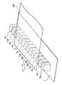
図2は、第一の実施形態による磁気検出装置10の磁気センサヘッド1の例を示す図である。上述したように、磁気センサヘッド1は複数個の感磁部11を有する。例えば、この図における磁気センサヘッド1は、感磁部11a~11nの14個の感磁部を備えている。
紙葉類通過領域の内側に存在する感磁部11は11c~11kである。紙葉類通過領域の内側に存在する感磁部11を第一の磁気検出部である第一の感磁部111と以下で記述する。また、第一の感磁部111が検出する磁気検出結果を第一の磁気検出結果という。
紙葉類通過領域の外側に位置する感磁部11は感磁部11a、11b、11l、11m、11nである。紙葉類通過領域の外側に位置する感磁部11を第二の磁気検出部である第二の感磁部112と以下で記述する。また、第二の感磁部112が検出する磁気検出結果を第二の磁気検出結果という。
第一の感磁部111になる感磁部11、および第二の感磁部112になる感磁部11は、紙葉類100の大きさ、紙葉類100の通過位置、感磁部11の数や配置によって異なり、例えば、光学的に紙葉類の通過位置を検出する処理部からの紙葉類の通過位置情報等に基づき決定される。
図3は、第一の実施形態による磁気検出装置10の磁気センサヘッド1が備える感磁部11の例を示す図である。感磁部11は、例えば半導体磁気抵抗素子(SMRE)を備える。この感磁部11は、この図で示されるように、インジウムアンチモン単結晶(InSb)半導体等の磁気抵抗素子R1とR2の2つと、磁気抵抗素子R1とR2の近傍背面に配置された永久磁石とを有する。この感磁部11において、永久磁石によるバイアス磁界中を磁性体が磁気抵抗素子に対して平行に移動すると、永久磁石の磁力線が変化して磁気抵抗素子の抵抗値が変化する。感磁部11では、2つの磁気抵抗素子R1、R2の抵抗値の差分が電気信号として取り出される。ここで、2つの磁気抵抗素子R1、R2は、紙葉類100が移動する方向に沿って配置されている。
また、感磁部11は、磁気抵抗素子R1、R2として、例えば、ニッケル(Ni)、鉄(Fe)などの強磁性金属を主成分とする合金の薄膜を有してもよい。
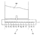
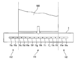
図4は、第一の実施形態による磁気検出装置10の磁気センサヘッド1における感磁部11の配列例を示す図である。図5は、第一の実施形態による磁気検出装置10の磁気センサヘッド1における感磁部11の他の配列例を示す図である。図6は、第一の実施形態による磁気検出装置10の磁気センサヘッド1における感磁部11の更に他の配列例を示す図である。図7は、第一の実施形態による磁気検出装置10の磁気センサヘッド1における感磁部11の更に他の配列例を示す図である。
磁気センサヘッド1は、図4~図7に示すように、紙葉類通過領域の位置、及び感磁部11の数によって区別される種々のタイプがある。磁気センサヘッド1は、複数の感磁部11を備えている。これらの感磁部11は、紙葉類100が移動する方向に対して直交する方向に一列に配置される。一列に配置される感磁部11の感磁面は、紙葉類100の全領域の磁気的特性を検出できるように配置される。また、一列に配置される感磁部11の感磁面は、紙葉類通過領域の外側の磁気的特性を検出できるように、紙葉類通過領域の外側にも配置される。
このように、磁気センサヘッド1では、個別に感磁領域を持つ感磁部11が一列に並べられ、紙葉類通過領域の内側と紙葉類通過領域の外側の両方で同様に感磁部11が並べられている。つまり、磁気センサヘッド1において、紙葉類100が磁気センサヘッド1を通過した際の紙葉類100の磁気的特性を検出する感磁部11と、紙葉類100が磁気センサヘッド1を通過した際の周辺環境に依存する磁気ノイズを検出する感磁部11とが一列に配置される。
理想的には紙葉類通過領域の内側にある第一の感磁部111の外側に少なくとも1つ以上の周辺環境に依存する磁気ノイズを検出するための第二の感磁部112を配置するのがよい。
例えば、図4は、紙葉類100が磁気センサヘッド1の12個の感磁部11のうち8個の感磁部11a~11hの領域を通過する場合を示している。この場合、感磁部11a~11hは、第一の感磁部111となる。そして、感磁部11i~11lは、第二の感磁部112となる。
図5は、紙葉類100が磁気センサヘッド1の12個の感磁部のうち8個の感磁部11c~11jの領域を通過する場合を示している。この場合、感磁部11c~11jは、第一の感磁部111となる。そして、感磁部11a、11b、11k、11lは、第二の感磁部112となる。
図6は、紙葉類100が磁気センサヘッド1の12個の感磁部のうち10個の感磁部11a~11jの領域を通過する場合を示している。この場合、感磁部11a~11jは、第一の感磁部111となる。そして、感磁部11k、11lは、第二の感磁部112となる。
図7は、紙葉類100が磁気センサヘッド1の14個の感磁部のうち10個の感磁部11c~11lの領域を通過する場合を示している。この場合、感磁部11c~11lは、第一の感磁部111となる。そして、感磁部11a、11b、11m、11nは、第二の感磁部112となる。
紙葉類100が一種類である場合、または紙葉類100の通過位置を制御できる場合には、磁気センサヘッド1の紙葉類通過領域はほぼ固定される。このため、紙葉類通過領域の外側に磁気ノイズ検出専用の感磁部11を配置してもよい。また、数種類の紙葉類100が混在する場合、または紙葉類100が一種類であっても磁気センサヘッド1上の紙葉類の通過位置がばらつく場合には、図示していない他の検出手段やセンサを用いて紙葉類の通過位置を検出し、第一の感磁部111と第二の感磁部112とを判定すればよい。例えば、光学的に紙葉類の通過位置を検出する処理部から紙葉類の通過位置情報を取得し、その情報に基づいて、磁気センサヘッド1における紙葉類通過領域の内側と紙葉類通過領域の外側とを判定してもよい。また、磁気センサヘッド1の直前に紙葉類100の有無を検出する近接センサを備える。そして、その近接センサが検出した紙葉類100の有無に基づいて、磁気センサヘッド1における紙葉類通過領域の内側と紙葉類通過領域の外側とを判定してもよい。
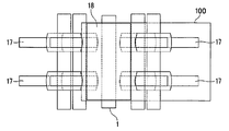
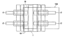
図8Aは、第一の実施形態による磁気検出装置10の磁気センサヘッド1の周辺を上面から見た場合の搬送構造の例を示す図である。また、図8Bは、第一の実施形態による磁気検出装置10の磁気センサヘッド1の周辺を正面から見た場合の搬送構造の例を示す図である。
図8A、図8Bで示されるように、第一の実施形態による磁気検出装置10は、磁気センサヘッド1の周辺に、搬送ローラ16と、搬送ベルト17と、搬送補助ローラ18と、を備えている。
第一の実施形態による磁気検出装置10は、搬送の上流から下流へと搬送ベルト17に挟持され移動する紙幣等の紙葉類100を放出し、磁気センサヘッド1により紙葉類100の磁気印刷情報を読み取り、再び紙葉類100を搬送ベルト17に挟持し、紙葉類100を移動させる。
図8Bでは、磁気センサヘッド1における感磁部11の感磁面を紙葉類が通過する際の、搬送補助の目的で搬送補助ローラ18が配置される。搬送補助ローラ18は、搬送ベルト17から放たれた紙葉類100を停滞させず、反対側の搬送ベルト17に挟持させる役割を果たしている。同時に、搬送補助ローラ18は、磁気センサヘッド1における感磁部11の感磁面上部での紙葉類100の通過位置を抑制する働きを果たす。また、搬送補助ローラ18は、紙葉類100を停滞させず、かつ、磁気センサヘッド1と紙葉類100との間の距離すなわち検出ギャップを一定以内に制限しながら紙葉類100を搬送する機能を果たす。
搬送補助ローラ18は、非磁性材料で実現される。搬送補助ローラ18は、搬送ベルト17によるベルト搬送速度と同等の外周速度で回転することで紙葉類100を移動する補助動力を生み出す。
ここで、第一の実施形態による磁気検出装置10を備える真偽判定装置30が行う処理の例を説明する。なお、ここで説明する例では、上流に配置された検査装置が光学的に紙葉類の通過位置を検出し、第一の感磁部111と第二の感磁部112は、その検査装置から受信した紙葉類の通過位置情報に基づき決定される。
まず、ユーザが紙葉類100を所定の箇所にセットする。すると、磁気検出装置10の上流に配置された検査装置が、後述する第三の実施形態で示すような検査や処理を紙葉類100に対して行う。そして、磁気検出装置10の上流に配置された検査装置は、その紙葉類100を磁気検出装置10に搬出する。
検査装置から紙葉類100が磁気検出装置10へ搬入されると、磁気検出装置10の搬送ベルト17は、紙葉類100を挟持する。そして、例えば図8Bについて説明したように、搬送ベルト17は、挟持した紙葉類100を放出し、搬送補助ローラ18を介して紙葉類100を停滞させずに反対側の搬送ベルト17へと紙葉類100を搬送する。
磁気センサヘッド1の感磁部11は、この搬送途中に紙葉類100が磁気センサヘッド1を通過した際の磁気的特性を検出する。そして、磁気センサヘッド1は、それぞれの感磁部11が検出した磁気的特性のアナログ信号を信号増幅回路2へ出力する。
信号増幅回路2は、磁気センサヘッド1からアナログ信号の入力を受けると、後段のA/D変換回路3の処理で必要となる信号振幅が得られるように、信号増幅回路2の各増幅器で入力されたそれぞれのアナログ信号を増幅する。そして、信号増幅回路2は、増幅されたそれぞれのアナログ信号をA/D変換回路3へ出力する。
A/D変換回路3は、信号増幅回路2から増幅されたアナログ信号の入力を受けると、入力されたそれぞれのアナログ信号を所定のタイミングでサンプリングする。そして、A/D変換回路3は、例えばサンプリングした信号をリファレンス信号と比較して、サンプリングした信号をデジタル信号に変換する。そして、A/D変換回路3は、変換されたそれぞれのデジタル信号を補償信号生成部4と環境磁気補正部5に出力する。なお、A/D変換回路3は、アナログ信号をデジタル信号へ必要な精度で変換できる回路であればよく、その回路方式は限定されない。
補償信号生成部4は、A/D変換回路3からそれぞれの磁気的特性のデジタル信号の入力を受ける。補償信号生成部4は、入力されたそれぞれの磁気的特性のデジタル信号に対して、複数のサンプルで時間軸方向に信号を平均化する「移動平均」処理或いは「スムージング」処理を行うことで信号の時間に対する急激な変動を緩やかにするローパスフィルタと同等の処理を行う。また、補償信号生成部4は、ローパスフィルタと同等の処理が行なわれたデジタル信号の「平均値」を算出し、記憶部に記録する。
また、環境磁気補正部5は、A/D変換回路3からそれぞれの磁気的特性のデジタル信号の入力を受ける。環境磁気補正部5は、入力されたそれぞれの磁気的特性のデジタル信号を記憶部に記録する。
磁気検出装置10の上流に配置された検査装置は、光学的に紙葉類100の通過位置を検出した結果である通過位置情報を所定のタイミングで補償信号生成部4と環境磁気補正部5に送信する。
補償信号生成部4は、検査装置から通過位置情報を受信すると、その通過位置情報に基づいて、磁気センサヘッド1において、各紙葉類100が通過する領域を特定する。つまり、補償信号生成部4は、磁気センサヘッド1の紙葉類通過領域を特定する。そして、補償信号生成部4は、特定した紙葉類通過領域の外側に位置する第二の感磁部112を特定する。
補償信号生成部4は、第二の感磁部112を特定すると、記憶部に記録したローパスフィルタと同等の処理を行ったデジタル信号のうち、その特定した第二の感磁部112が出力したデータ(第二の出力信号)を記憶部から読み出す。ここで、補償信号生成部4が読み出したデータは、紙葉類通過領域の外側に位置する感磁部11が検出した磁気的特性であり、周辺環境に依存する磁気ノイズを示す。そして、補償信号生成部4は、記憶部から読み出した、周辺環境に依存する磁気ノイズを示すデータを環境磁気補正部5に出力する。
また、環境磁気補正部5は、検査装置から紙葉類100についての通過位置情報を受信すると、その通過位置情報に基づいて、磁気センサヘッド1において紙葉類100が通過する領域を特定する。つまり、環境磁気補正部5は、紙葉類通過領域を特定する。そして、境磁気補正部5は、特定した紙葉類通過領域の内側に位置する第一の感磁部111を特定する。
環境磁気補正部5は、環境磁気補正部5が第一の感磁部111を特定すると、記憶部に記録したデジタル信号のうち、特定した第一の感磁部111が出力したデータ(第一の出力信号)を記憶部から読み出す。ここで、環境磁気補正部5が読み出したデータは、紙葉類通過領域の内側に位置する感磁部11が検出した磁気的特性であり、周辺環境に依存する磁気ノイズを含んだ紙葉類100の磁気的特性を示す。そして、環境磁気補正部5は、記憶部から読み出した紙葉類100の磁気的特性を示すデータから、補償信号生成部4から入力された、或いは入力される周辺環境に依存する磁気ノイズを示すデータを減算する。
環境磁気補正部5が行う減算により、第一の感磁部111が検出した周辺環境に依存する磁気ノイズを含んだ紙葉類100の磁気的特性から第二の感磁部112が検出した周辺環境に依存する磁気ノイズを取り除くことができる。これにより、環境磁気補正部5は、紙葉類100のみの磁気的特性を特定できる。そして、環境磁気補正部5は、その減算した結果を磁気検査判定処理部6に出力する。
なお、補償信号生成部4は、紙葉類100が移動する方向に対して直交する方向の一端と他端のそれぞれに対応する第一の感磁部111に隣接する第二の感磁部112を特定する。つまり、紙葉類通過領域の両側に位置する第二の感磁部112を特定する。そして、補償信号生成部4は、その特定したそれぞれの第二の感磁部112が検出した磁気的特性に対応するデジタル信号に対して、それぞれ移動平均の処理や平均値を求める処理を行う。更に、補償信号生成部4は、磁気センサヘッド1における感磁部11の配列方向に沿っての磁気ノイズの勾配を含む補償信号を生成する。そして、環境磁気補正部5は、補償信号生成部4が生成した磁気センサヘッド1における感磁部11の配列方向に沿っての磁気ノイズの勾配を含む補償信号を用いて減算する処理を行ってもよい。すなわち、例えば、補償信号生成部4は、生成した補償信号を磁気センサヘッド1方向の距離に応じて線形近似する。そして、環境磁気補正部5は、各感磁部11の位置に応じた補償信号を用いて減算処理を行えばよい。
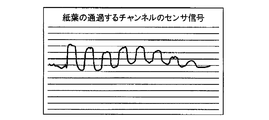
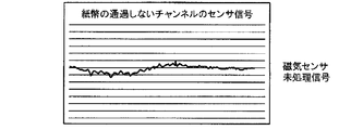
図9A~図9Dは、補償信号生成部4と環境磁気補正部5の処理におけるデジタル信号の一例を示す図である。図9Aは、環境磁気補正部5が特定した第一の感磁部111が検出した周辺環境に依存する磁気ノイズを含んだ紙葉類100の磁気的特性を示すデジタル信号である。図9Bは、補償信号生成部4が特定した第二の感磁部112が検出した周辺環境に依存する磁気ノイズを示すデジタル信号である。図9Cは、補償信号生成部4が特定した第二の感磁部112が検出した周辺環境に依存する磁気ノイズを示すデジタル信号に対してローパスフィルタと同等の処理を行った後のデジタル信号である。また、図9Dは、図9Aで示した第一の感磁部111が検出した周辺環境に依存する磁気ノイズを含んだ紙葉類100の磁気的特性を示すデジタル信号から、図9Cで示した周辺環境に依存する磁気ノイズを示すデジタル信号に対してローパスフィルタと同等の処理を行った後のデジタル信号を減じた信号である。このデジタル信号は、紙葉類100のみの磁気的特性を示している。
以上の説明は、磁気検出装置10が行う処理に関する。磁気検出装置10がこのような信号処理を行うことで、周辺環境に依存する磁気ノイズを含む第一の感磁部111の検出した信号から第二の感磁部112が検出した磁気ノイズを取り除いた、紙葉類100のみの磁気的特性を特定することができる。
次に、磁気検査判定処理部6は、環境磁気補正部5から、第一の感磁部からのデジタル信号から磁気ノイズを示すデジタル信号を減算したデジタル信号の入力を受ける。すると、磁気検査判定処理部6は、判定基準レベルメモリ7から予め記録した真偽判定のパラメータを読み出す。そして、磁気検査判定処理部6は、環境磁気補正部5から入力されたデジタル信号を読み出した真偽判定のパラメータと比較し、例えば、二乗平均値を求める。磁気検査判定処理部6は、二乗平均値が所定の範囲に入っている場合に紙葉類100が本物であると判定する。また、磁気検査判定処理部6は、二乗平均値が所定の範囲に入っていない場合に紙葉類100が偽物であると判定する。
以上の説明は、第一の実施形態による磁気検出装置10を備える真偽判定装置30が行う処理に関する。
なお、磁気検査判定処理部6は、補償信号生成部4が生成した磁気センサヘッド1における感磁部11の配列方向に沿っての磁気ノイズの勾配を含めた補償信号を用いて補正されたデータを用いて判定してもよい。また、第一の実施形態による磁気検出装置10において、第二の感磁部112を既知の技術で用いられている温度補正のためのセンサとして使用してもよい。
以上のように、第一の実施形態による磁気検出装置10は、紙葉類通過領域の内側に位置する第一の感磁部111が検出した磁気検出結果(第一の出力信号)と、紙葉類通過領域の外側に位置する第二の感磁部112が検出した磁気検出結果(第二の出力信号)とに基づいて、周辺環境に依存する磁気ノイズを含んだ紙葉類100の磁気的特性を示すデジタル信号から周辺環境に依存する磁気ノイズを示すデジタル信号を減算する。
したがって、第一の実施形態による磁気検出装置10は、紙葉類100のみの磁気的特性を特定でき、紙葉類100の磁気的特性をより高い精度で検出することができる。また、第一の実施形態による磁気検出装置10を備える真偽判定装置30は、磁気検出装置10によって高い精度で検出した紙葉類100の磁気的特性を、真偽判定のパラメータと比較することができ、これにより真偽の判定精度を高めることができる。
<第二の実施形態>
第二の実施形態による磁気検出装置10の構成は、第一の実施形態と同様の構成である。また、第二の実施形態による磁気検出装置10を備える真偽判定装置30は、第一の実施形態と同様の構成である。ただし、第二の実施形態による磁気検出装置10において、磁気センサヘッド1は磁気シールドされている。
第二の実施形態による磁気検出装置10の構成は、第一の実施形態と同様の構成である。また、第二の実施形態による磁気検出装置10を備える真偽判定装置30は、第一の実施形態と同様の構成である。ただし、第二の実施形態による磁気検出装置10において、磁気センサヘッド1は磁気シールドされている。
図10Aは、第二の実施形態による磁気検出装置10の磁気センサヘッド1の周辺を上面から見た場合の搬送構造の例を示す図である。図10Bは、第二の実施形態による磁気検出装置10の磁気センサヘッド1の周辺を側面から見た場合の搬送構造の例を示す図である。
図10A、図10Bで示されるように、第二の実施形態による磁気検出装置10は、第一の実施形態による磁気検出装置10の構成に加え、強磁性体材料を用いた磁気シールド構造体である磁気シールドカバー19を備えている。
磁気シールドカバー19は、磁気センサヘッド1の感磁部11が紙葉類100の磁気的特性を検出する際に周辺磁界環境の影響を抑制する。磁気センサヘッド1側に設けられた磁気シールドカバー19は、感磁面を除く感磁部11の5つの面(4つの側面および背面を含む)を、鉄等の透磁率の高い材料で囲む構造を有する。なお、感磁部11は、感磁面が、搬送される検査対象の紙葉類100の面に向くように設置される。
さらに、搬送補助ローラ18側に設けられた磁気シールドカバー19は、搬送補助ローラ18を囲い込む構造を有する。
このため、磁気シールドカバー19は、磁気センサヘッド1の背面などから伝達されるベアリングなどの回転駆動に起因する磁気ノイズによる磁気的特性の検出への影響を抑制することができる。
磁気シールドカバー19は、近傍の磁界発生源の狭域磁界(狭域の磁力線)をシールド材内部に引き込み、磁気シールドカバー19の内部の磁気センサヘッド1における感磁部11の感磁面やバイアス磁界領域に侵入する狭域の磁力線の影響を低減する。また、磁気シールドカバー19は、磁気センサヘッド1の感磁部11に集中している磁力線分布を均一化する効果もある。また、磁気シールドカバー19は、感磁部11毎に影響差が現れる周辺磁界環境においても、各感磁部11に均等に磁界影響が及ぶように周辺磁界の影響を緩和する働きを有している。
また、磁気シールドカバー19は、近傍狭域磁界による感磁部11の磁気的特性の検出への影響を低減すると共に、その影響を均一化することができる。同様に、磁気シールドカバー19は、装置内の磁界源であるモータやトランス等の強磁界による感磁部11の磁気的特性の検出への影響も減衰すると共に、その影響を均一化することができる。
従って、第一の実施形態と同様の磁気検出装置10の機能部に加え、更にシールドカバー19を備える第二の実施形態による磁気検出装置10では、磁気センサヘッド1をシールドカバー19で囲むことで、磁気センサヘッド1周辺での狭域の磁界による感磁部11の磁気的特性の検出への影響を減衰し緩和する。また、磁気センサヘッド1をシールドカバー19で囲むことで、磁気センサヘッド1の遠方にある広域で強度の磁界による感磁部11の磁気的特性の検出への影響を減衰し緩和し、環境磁界による各感磁部11への影響を均等にすることができる。
第二の実施形態による磁気検出装置10は、磁気センサヘッド1の感磁部11の検出精度が向上し、取得信号品質である信号S/N比を向上させることが可能となる。このため、磁気検出装置10は、紙葉類100のみの磁気的特性を特定でき、より高い精度で紙葉類100の磁気的特性を検出することができる。
また、第二の実施形態による磁気検出装置10を備える真偽判定装置30は、磁気検出装置10により高い精度で検出した紙葉類100の磁気的特性に基づいて、より高い精度の磁気的特性を真偽判定のパラメータと比較することができ、真偽の判定精度を高めることができる。
<第三の実施形態>
図11は、第三の実施形態による紙葉類処理装置20の構成を示す図である。
図11は、第三の実施形態による紙葉類処理装置20の構成を示す図である。
第三の実施形態では、紙葉類100として紙幣が使用される。第三の実施形態による紙葉類処理装置20は、第一の実施形態による磁気検出装置10を備える真偽判定装置30と、検査装置21~24と、検査装置総合判定処理部25と、区分制御部26と、紙幣処理機制御メイン27と、を備える。真偽判定装置30は、磁気センサヘッド1、信号増幅回路2、A/D変換回路3、補償信号生成部4、環境磁気補正部5、磁気検査判定処理部6、判定基準レベルメモリ7を備える。
ここで、第三の実施形態による紙葉類処理装置20が備える検査装置21~24は、紙葉類100の状態に応じて紙葉類100を真偽/廃棄/再流通/排除に区分するための検査を実施する。例えば、検査装置21~24は、紙葉類100の切れを検出する切れ検出装置、紙葉類100の厚みを検査する厚み検査装置、紙葉類100の形状や透かしを検出する形状・透かし検出装置、紙葉類100の光学パターンを判定する光学パターン判定装置などである。
検査装置総合判定処理部25は、検査装置21~24および磁気検出装置10の検査結果に基づいて、紙葉類100の真偽および紙葉類100の劣化の程度を特定する処理部である。また、検査装置総合判定処理部25は、検査装置21~24および磁気検出装置10における紙葉類100の搬送を制御する処理部である。この検査装置総合判定処理部25が行う制御により、磁気検出装置10は、磁気センサヘッド1において紙葉類100が通過する位置を知ることができる。そして、検査装置総合判定処理部25による制御が高精度である場合には、磁気検出装置10は、第一の感磁部111と第二の感磁部112とを事前に特定できる。
区分制御部26は、検査装置総合判定処理部25が特定した紙葉類100の真偽および紙葉類100の劣化の程度に基づいて、廃棄/再流通/排除の何れかに紙葉類100を区分する処理部である。
紙幣処理機制御メイン27は、区分制御部26が区分した廃棄、再流通、排除の処理を実行する。
ここで、第三の実施形態による紙葉類処理装置20の処理の例を説明する。
まず、ユーザが紙葉類100を所定の箇所にセットする。その後、紙葉類処理装置20を稼働すると、紙葉類100は1枚ずつ取出されて搬送され、紙葉類100は検査装置21、検査装置22、検査装置23、磁気検出装置10、検査装置24の順番でこれらの装置21、22、23、10、24を通過し、それぞれの装置21、22、23、10、24は紙葉類100に対してそれぞれの検査処理を実施する。
検査装置21は、紙葉類100の切れを検査する。検査装置21は、例えば、紙葉類100が搬送される搬送路上にローラ等の機構を備え、この機構により紙葉類100の端部に存在する切れ目を開く。そして、検査装置21は、開かれた切れ目を通過する光によって切れ目の有無を検査する。この切れ目検査は、再流通に適さない紙葉類100を検出するためのものである。ここで、紙葉類100に切れ目が検出された場合、検査装置21は切れ目の検出を検査装置総合判定処理部25に報知する。
検査装置22では、紙葉類100の厚さを検査する。検査装置22は、例えば、紙葉類100が搬送される搬送路上に厚み検知センサなどの紙葉類100の厚さを検出する機構を備える。検査装置22は、検出した厚さが所定の厚さの範囲内にあるか否かを判定する。この検査は、紙葉類100の厚さが所定以上である場合は2枚以上の紙葉類が重なっていると判断し、検査装置22は、その結果を検査装置総合判定処理部25に報知する。
検査装置23では、紙葉類100の形状や透かしを検査する。検査装置23は、例えば、紙葉類100が搬送される搬送路上に紙葉類100の透過光画像の特徴を検出する機構を備える。検査装置23は、検出した特徴を本物の紙幣の特徴と比較してその結果を検査装置総合判定処理部25に報知する。
検査装置24では光学パターンを検査する。検査装置24は、例えば、紙葉類100が搬送される搬送路上に紙葉類100の反射光画像の特徴を検出する機構を備える。検査装置24は、検出した特徴を本物の紙幣の特徴と比較してその結果を検査装置総合判定処理部25に報知する。
磁気検出装置10では、紙葉類100の磁気的特性の検出により紙葉類100真偽を検査する。磁気検出装置10を備える真偽判定装置30が行う真偽の判定は、例えば、第一の実施形態で示した処理による真偽の判定である。そのため、ここでの詳細な説明は省略する。なお、真偽判定装置30は、真偽判定装置30が判定した結果を、検査装置総合判定処理部25に報知する。
検査装置総合判定処理部25は、検査装置21~24及び真偽判定装置30から報知された結果に基づいて、搬送される紙葉類100が真券であるか/廃棄すべきか/再流通すべきか/排除すべきかを総合的に判定する。検査装置総合判定処理部25は、この判定結果を区分制御部26に報知する。
区分制御部26は、その報知情報に基づいて、紙葉類100の区分先を決定する。
以上のように、第三の実施形態による紙葉類処理装置20は、紙葉類100に対する廃棄/再流通/排除のための検査の1つとして、第一の実施形態による磁気検出装置10を備える真偽判定装置30による検査を実施する。
第三の実施形態による紙葉類処理装置20の磁気検出装置10は、紙葉類100の磁気を高精度に検出することができる。そのため、第三の実施形態による磁気検出装置10を備える真偽判定装置30を備える紙葉類処理装置20は、高精度で検出した紙葉類100の磁気的特性に基づいて、高精度な磁気的特性を真偽判定のパラメータと比較することができ、真偽の判定精度を高めることができる。
なお、紙葉類処理装置20は、このような紙葉類100に対する廃棄/再流通/排除するものに限定されず、少なくとも紙葉類100の磁気情報に基づいて紙葉類100の真偽を判定して紙葉類100を区分できるものであればよい。
以上述べた少なくとも一つの実施形態の磁気検出装置10によれば、磁気センサヘッド1における紙葉類通過領域の内側に位置する第一の感磁部111が検出した磁気検出結果(第一の出力信号)と、磁気センサヘッド1における紙葉類通過領域の外側に位置する第二の感磁部112が検出した磁気検出結果(第二の出力信号)とに基づいて、周辺環境に依存する磁気ノイズを含んだ紙葉類100の磁気的特性を示すデジタル信号から周辺環境に依存する磁気ノイズを示すデジタル信号を減算する。
したがって、第一の実施形態による磁気検出装置10は、紙葉類100のみの磁気的特性を特定でき、より高い精度で紙葉類100の磁気的特性を検出することができる。また、第一の実施形態による磁気検出装置10を備える真偽判定装置30を備える紙葉類処理装置20は、磁気検出装置10により高い精度で検出した紙葉類100の磁気的特性に基づいて、より高い精度の磁気的特性を真偽判定のパラメータと比較することができ、真偽の判定精度を高めることができる。
本発明のいくつかの実施形態を説明したが、これらの実施形態は、例として提示したものであり、発明の範囲を限定することは意図していない。これら実施形態は、その他の様々な形態で実施されることが可能であり、発明の要旨を逸脱しない範囲で、種々の省略、置き換え、変更を行うことができる。これら実施形態やその変形は、発明の範囲や要旨に含まれると同様に、特許請求の範囲に記載された発明とその均等の範囲に含まれるものである。
1・・・磁気センサヘッド
2・・・信号増幅回路
3・・・A/D変換回路
4・・・補償信号生成部
5・・・環境磁気補正部
6・・・磁気検査判定処理部
7・・・判定基準レベルメモリ
10・・・磁気検出装置
11・・・感磁部
16・・・搬送ローラ
17・・・搬送ベルト
18・・・搬送補助ローラ
19・・・磁気シールドカバー
20・・・紙葉類処理装置
21・・・検査装置
22・・・検査装置
23・・・検査装置
24・・・検査装置
25・・・検査装置総合判定処理部
26・・・区分制御部
27・・・紙幣処理機制御メイン
30・・・真偽判定装置
100・・・紙葉類
111・・・第一の感磁部
112・・・第二の感磁部
2・・・信号増幅回路
3・・・A/D変換回路
4・・・補償信号生成部
5・・・環境磁気補正部
6・・・磁気検査判定処理部
7・・・判定基準レベルメモリ
10・・・磁気検出装置
11・・・感磁部
16・・・搬送ローラ
17・・・搬送ベルト
18・・・搬送補助ローラ
19・・・磁気シールドカバー
20・・・紙葉類処理装置
21・・・検査装置
22・・・検査装置
23・・・検査装置
24・・・検査装置
25・・・検査装置総合判定処理部
26・・・区分制御部
27・・・紙幣処理機制御メイン
30・・・真偽判定装置
100・・・紙葉類
111・・・第一の感磁部
112・・・第二の感磁部
Claims (15)
- 紙葉類が移動する方向に対して直交する方向に、前記紙葉類の幅よりも長い長さで一列に配置された、第一の感磁部と第二の感磁部とを有する複数個の感磁部を有する磁気センサヘッドと、
前記第一の感磁部が出力する第一の出力信号を、前記第二の感磁部が出力する第二の出力信号に基づいて補正する環境磁気補正部と、
を備え、
前記磁気センサヘッドは前記磁気センサヘッドを通過する紙葉類に対向する紙葉類通過領域を有し、
前記第一の感磁部は前記紙葉類通過領域の内側に位置し、また
前記第二の感磁部は前記紙葉類通過領域の外側に位置する、
ことを特徴とする磁気検出装置。 - 前記複数の感磁部の感磁面は、同一面上、かつ一直線上に形成されることを特徴とする請求項1に記載の磁気検出装置。
- 前記環境磁気補正部は、前記第二の出力信号に対して時間軸方向に対する急激な変化を取り除く処理を行った処理結果に基づいて、前記第一の出力信号を補正することを特徴とする請求項1に記載の磁気検出装置。
- 前記第二の出力信号に対して時間軸方向に対する急激な変化を取り除く処理は、前記第二の出力信号を時間軸方向においてサンプリングし、複数のサンプル信号を平均化する処理であることを特徴とする請求項3に記載の磁気検出装置。
- 前記環境磁気補正部は、前記紙葉類通過領域の両側に位置する前記第二の感磁部が出力する前記第二の出力信号に基づいて前記第二の出力信号を線形近似することによって得られた磁気ノイズの勾配に基づいて、前記前記第一の出力信号を補正することを特徴とする請求項1記載の磁気検出装置。
- 前記環境磁気補正部は、前記紙葉類の通過位置に基づいて、前記第一の感磁部を特定することを特徴とする請求項1に記載の磁気検出装置。
- さらに、前記第二の感磁部が出力する第二の出力信号に対して時間軸方向に対する急激な変化を取り除く処理を行い、処理結果を出力する補償信号生成部を有することを特徴とする請求項2項に記載の磁気検出装置。
- 前記第二の出力信号は時間軸方向においてサンプリングされ、前記補償信号生成部はサンプリングされた複数の信号を平均化する移動平均処理を行うことを特徴とする請求項7に記載の磁気検出装置。
- 前記磁気センサヘッドを囲む磁気シールドカバーを、さらに備えることを特徴とする請求項2項に記載の磁気検出装置。
- 前記磁気センサヘッドに対向し、前記磁気センサヘッドを通過する前記紙葉類と前記磁気センサヘッドとの間の距離を一定以内に制限するローラ、及び
前記磁気センサヘッド及び前記ローラを囲む磁気シールドカバーと、
を、さらに備えることを特徴とする請求項1項に記載の磁気検出装置。 - 紙葉類が移動する方向に対して直交する方向に、前記紙葉類の幅よりも長い長さで一列に配置された、第一の感磁部と第二の感磁部とを有する複数個の感磁部を有する磁気センサヘッドと、
前記第一の感磁部が出力する第一の出力信号を、前記第二の感磁部が出力する第二の出力信号に基づいて補正する環境磁気補正部と、
を備え、
前記磁気センサヘッドは前記磁気センサヘッドを通過する紙葉類に対向する紙葉類通過領域を有し、
前記第一の感磁部は前記紙葉類通過領域の内側に位置し、また
前記第二の感磁部は前記紙葉類通過領域の外側に位置する
磁気検出装置と、
前記磁気検出装置の出力に基づいて紙葉類の真偽を判定する真偽判定装置と、
前記真偽判定装置の出力に基づいて紙葉類を区分する区分制御部と、
を備えることを特徴とする紙葉類処理装置。 - さらに、前記磁気センサヘッドを通過する紙葉類の通過位置を検出して、通過位置情報を前記前記環境磁気補正部へ送信する検査部を備え、
前記前記環境磁気補正部は、前記通過位置情報に基づいて前記第一の感磁部を特定することを特徴とする請求項11に記載の紙葉類処理装置。 - 前記第二の感磁部が出力する第二の出力信号に対して時間軸方向に対する急激な変化を取り除く処理を行い、処理結果を出力する補償信号生成部を、さらに備え、
前記環境磁気補正部は、前記第一の感磁部が出力する第一の出力信号を、前記補償信号生成部が出力する処理結果に基づいて補正することを特徴とする請求項11に記載の紙葉類処理装置。 - さらに、前記磁気センサヘッドを通過する紙葉類の通過位置を検出して、通過位置情報を前記前記環境磁気補正部および前記補償信号生成部へ送信する検査部を備え、
前記前記環境磁気補正部は、前記通過位置情報に基づいて前記第一の感磁部を特定し、また前記補償信号生成部は、前記通過位置情報に基づいて前記第二の感磁部を特定することを特徴とする請求項13に記載の紙葉類処理装置。 - 通過する紙葉類に対向する紙葉類通過領域を有し、前記紙葉類が移動する方向に対して直交する方向に、前記紙葉類の幅よりも長い長さで一列に配置された複数個の感磁部を並べた磁気センサヘッドと、
前記紙葉類通過領域の内側に位置する前記感磁部が出力する第一の出力信号を、前記紙葉類通過領域の外側に位置する前記感磁部が出力する第二の出力信号に基づいて補正する環境磁気補正部と、
を備えることを特徴とする磁気検出装置。
Priority Applications (2)
| Application Number | Priority Date | Filing Date | Title |
|---|---|---|---|
| EP14834024.3A EP3032252B2 (en) | 2013-08-09 | 2014-08-08 | Magnetic detection device and paper sheet processing device |
| US15/018,171 US9965914B2 (en) | 2013-08-09 | 2016-02-08 | Magnetic detecting device and sheet processing apparatus |
Applications Claiming Priority (2)
| Application Number | Priority Date | Filing Date | Title |
|---|---|---|---|
| JP2013-167049 | 2013-08-09 | ||
| JP2013167049A JP6226629B2 (ja) | 2013-08-09 | 2013-08-09 | 磁気検出装置及び紙葉類処理装置 |
Related Child Applications (1)
| Application Number | Title | Priority Date | Filing Date |
|---|---|---|---|
| US15/018,171 Continuation US9965914B2 (en) | 2013-08-09 | 2016-02-08 | Magnetic detecting device and sheet processing apparatus |
Publications (1)
| Publication Number | Publication Date |
|---|---|
| WO2015019624A1 true WO2015019624A1 (ja) | 2015-02-12 |
Family
ID=52460974
Family Applications (1)
| Application Number | Title | Priority Date | Filing Date |
|---|---|---|---|
| PCT/JP2014/004144 Ceased WO2015019624A1 (ja) | 2013-08-09 | 2014-08-08 | 磁気検出装置及び紙葉類処理装置 |
Country Status (4)
| Country | Link |
|---|---|
| US (1) | US9965914B2 (ja) |
| EP (1) | EP3032252B2 (ja) |
| JP (1) | JP6226629B2 (ja) |
| WO (1) | WO2015019624A1 (ja) |
Families Citing this family (10)
| Publication number | Priority date | Publication date | Assignee | Title |
|---|---|---|---|---|
| KR101736569B1 (ko) | 2015-05-22 | 2017-05-16 | 주식회사 엘지씨엔에스 | 매체감별장치 및 그 감별방법 |
| CN106023409A (zh) * | 2016-06-30 | 2016-10-12 | 中钞长城金融设备控股有限公司 | 纸币安全线磁性编码的检测装置及其方法 |
| DE102017001947A1 (de) | 2017-02-28 | 2018-08-30 | Giesecke+Devrient Currency Technology Gmbh | Magnetische Prüfung von Wertdokumenten |
| EP3410075B1 (en) * | 2017-05-30 | 2020-10-07 | MEAS France | Temperature compensation for magnetic field sensing devices and a magnetic field sensing device using the same |
| CN107622559A (zh) * | 2017-07-18 | 2018-01-23 | 杭州科凡电子有限公司 | 纸币测量系统及方法 |
| DE102019109337B8 (de) * | 2019-04-09 | 2020-06-04 | Dr. Brockhaus Messtechnik GmbH & Co. KG | Vorrichtung und Verfahren zum Messen magnetischer Eigenschaften eines ferromagnetischen Endlosbandes |
| CN112652288B (zh) * | 2019-09-25 | 2024-08-09 | 深圳怡化电脑股份有限公司 | 消除磁性浮动辊磁噪声的方法、装置及终端设备 |
| EP3885778B1 (en) * | 2020-03-23 | 2024-02-07 | Melexis Technologies SA | Position sensor devices, methods and systems based on magnetic field gradients |
| CN116666036B (zh) * | 2023-05-17 | 2024-02-13 | 珠海多创科技有限公司 | 消磁模块和电流传感器 |
| CN118671671B (zh) * | 2024-08-20 | 2024-12-10 | 杭州海康威视数字技术股份有限公司 | 基于多磁头磁电阻效应传感器的位置测量方法及传感器 |
Citations (10)
| Publication number | Priority date | Publication date | Assignee | Title |
|---|---|---|---|---|
| JPH0458174A (ja) * | 1990-06-28 | 1992-02-25 | Koreyoshi Kakigi | 刻印検出用磁気センサ |
| JP2585558B2 (ja) | 1986-12-26 | 1997-02-26 | グローリー工業株式会社 | マルチチヤンネル型磁気ヘツド |
| JP2000346920A (ja) * | 1999-03-26 | 2000-12-15 | Toyota Central Res & Dev Lab Inc | 透磁率測定装置および透磁率測定方法 |
| JP2002098744A (ja) * | 2000-09-25 | 2002-04-05 | Sankyo Seiki Mfg Co Ltd | 磁気センサ |
| JP2005257440A (ja) * | 2004-03-11 | 2005-09-22 | Hitachi Omron Terminal Solutions Corp | 紙葉類識別装置 |
| JP2009121872A (ja) * | 2007-11-13 | 2009-06-04 | Oki Electric Ind Co Ltd | 磁気センサ検出信号の検出方法及び検出装置 |
| JP2009169712A (ja) * | 2008-01-17 | 2009-07-30 | Nidec Sankyo Corp | 磁気文字認識方法及び磁気文字認識装置 |
| JP4841662B2 (ja) | 2009-09-30 | 2011-12-21 | グローリー株式会社 | 磁気検出装置及びそのキャンセルヘッド出力のフィードバック方法 |
| JP2012043361A (ja) * | 2010-08-23 | 2012-03-01 | Toshiba Corp | 紙葉類検査装置、及び紙葉類検査装置を備える紙葉類処理装置 |
| JP2013120538A (ja) * | 2011-12-08 | 2013-06-17 | Nidec Sankyo Corp | 磁気センサ装置 |
Family Cites Families (15)
| Publication number | Priority date | Publication date | Assignee | Title |
|---|---|---|---|---|
| GB1202534A (en) * | 1966-11-19 | 1970-08-19 | Elliott Brothers London Ltd | Improvements relating to magnetically sensitive arrangements |
| EP0057972B1 (en) * | 1981-01-12 | 1986-10-08 | Kabushiki Kaisha Toshiba | A device for detecting a metal strip embedded in paper |
| DE3738455A1 (de) | 1986-11-25 | 1988-06-01 | Landis & Gyr Ag | Anordnung zum messen eines flussarmen magnetfeldes |
| US6667615B2 (en) | 2000-02-10 | 2003-12-23 | Sankyo Seiki Mfg. Co., Ltd. | Coin identifying device using magnetic sensors |
| JP2001266205A (ja) | 2000-03-22 | 2001-09-28 | Toshiba Corp | 磁気情報検出装置 |
| JP4227038B2 (ja) | 2004-02-27 | 2009-02-18 | 株式会社東芝 | 磁性体検知装置 |
| JP2006350820A (ja) | 2005-06-17 | 2006-12-28 | Toshiba Corp | 紙葉類識別装置 |
| KR100758123B1 (ko) | 2006-06-30 | 2007-09-11 | 노틸러스효성 주식회사 | 지폐감별장치의 간격조절구조 |
| ATE537524T1 (de) * | 2007-05-17 | 2011-12-15 | Nidec Sankyo Corp | Verfahren und vorrichtung zur magnetischen zeichenerkennung |
| US7383993B1 (en) | 2007-11-02 | 2008-06-10 | International Business Machines Corporation | Combined magnetic shield member and pressure pad for a magnetic reader |
| CN102077253B (zh) | 2008-06-25 | 2014-05-14 | 乐金信世股份有限公司 | 介质鉴别装置及其鉴别方法 |
| US8297507B2 (en) | 2008-09-11 | 2012-10-30 | Toshiba International Corporation | Magnetoresistive detection system and method for detection of magnetic image of bank notes |
| DE102011110138A1 (de) * | 2011-08-15 | 2013-02-21 | Meas Deutschland Gmbh | Messvorrichtung zum Messen magnetischer Eigenschaften der Umgebung der Messvorrichtung |
| DE102011121876A1 (de) | 2011-12-21 | 2013-06-27 | Giesecke & Devrient Gmbh | Verfahren für die Kompensation von Störungen |
| JP6548868B2 (ja) * | 2014-03-13 | 2019-07-24 | 株式会社東芝 | 磁気検査装置、および紙葉類処理装置 |
-
2013
- 2013-08-09 JP JP2013167049A patent/JP6226629B2/ja active Active
-
2014
- 2014-08-08 WO PCT/JP2014/004144 patent/WO2015019624A1/ja not_active Ceased
- 2014-08-08 EP EP14834024.3A patent/EP3032252B2/en active Active
-
2016
- 2016-02-08 US US15/018,171 patent/US9965914B2/en active Active
Patent Citations (10)
| Publication number | Priority date | Publication date | Assignee | Title |
|---|---|---|---|---|
| JP2585558B2 (ja) | 1986-12-26 | 1997-02-26 | グローリー工業株式会社 | マルチチヤンネル型磁気ヘツド |
| JPH0458174A (ja) * | 1990-06-28 | 1992-02-25 | Koreyoshi Kakigi | 刻印検出用磁気センサ |
| JP2000346920A (ja) * | 1999-03-26 | 2000-12-15 | Toyota Central Res & Dev Lab Inc | 透磁率測定装置および透磁率測定方法 |
| JP2002098744A (ja) * | 2000-09-25 | 2002-04-05 | Sankyo Seiki Mfg Co Ltd | 磁気センサ |
| JP2005257440A (ja) * | 2004-03-11 | 2005-09-22 | Hitachi Omron Terminal Solutions Corp | 紙葉類識別装置 |
| JP2009121872A (ja) * | 2007-11-13 | 2009-06-04 | Oki Electric Ind Co Ltd | 磁気センサ検出信号の検出方法及び検出装置 |
| JP2009169712A (ja) * | 2008-01-17 | 2009-07-30 | Nidec Sankyo Corp | 磁気文字認識方法及び磁気文字認識装置 |
| JP4841662B2 (ja) | 2009-09-30 | 2011-12-21 | グローリー株式会社 | 磁気検出装置及びそのキャンセルヘッド出力のフィードバック方法 |
| JP2012043361A (ja) * | 2010-08-23 | 2012-03-01 | Toshiba Corp | 紙葉類検査装置、及び紙葉類検査装置を備える紙葉類処理装置 |
| JP2013120538A (ja) * | 2011-12-08 | 2013-06-17 | Nidec Sankyo Corp | 磁気センサ装置 |
Non-Patent Citations (1)
| Title |
|---|
| See also references of EP3032252A4 |
Also Published As
| Publication number | Publication date |
|---|---|
| JP6226629B2 (ja) | 2017-11-08 |
| EP3032252B1 (en) | 2017-09-27 |
| EP3032252B2 (en) | 2020-07-22 |
| EP3032252A4 (en) | 2016-09-07 |
| EP3032252A1 (en) | 2016-06-15 |
| US20160155282A1 (en) | 2016-06-02 |
| JP2015034794A (ja) | 2015-02-19 |
| US9965914B2 (en) | 2018-05-08 |
Similar Documents
| Publication | Publication Date | Title |
|---|---|---|
| JP6226629B2 (ja) | 磁気検出装置及び紙葉類処理装置 | |
| KR101413952B1 (ko) | 자기 패턴 검출 장치 | |
| JP5719515B2 (ja) | 磁気センサ装置 | |
| JP5901768B2 (ja) | 自身の周辺の磁気的な特性を測定するための測定装置 | |
| US10677755B2 (en) | Apparatus and method for detecting inner defects of steel plate | |
| JP5889697B2 (ja) | 紙葉類磁性評価装置及び紙葉類磁性評価方法 | |
| US20150198561A1 (en) | Magnetic sensor device | |
| CN107148641B (zh) | 图像读取装置 | |
| CN108291947A (zh) | 磁场传感器以及具备其的磁场检测装置 | |
| US20130161391A1 (en) | Method for the compensation of disturbances | |
| KR20150126004A (ko) | 화상 판독 장치 | |
| JP6159112B2 (ja) | 金属検出装置 | |
| JP2014092365A (ja) | 金属検出装置 | |
| JP2004037216A (ja) | 漏洩磁束探傷方法 | |
| WO2015125340A1 (ja) | 表面特性検査選別装置、表面特性検査選別システム及び表面特性検査選別方法 | |
| JP7091813B2 (ja) | 異物検査方法、異物検査装置及びスリッター | |
| JP6296843B2 (ja) | 紙葉類処理装置 | |
| JP2014010118A (ja) | 磁気センサ装置 | |
| JP6674169B2 (ja) | 異物混入検査装置及びその方法 | |
| WO2014155866A1 (ja) | 異物検出装置および異物検出方法 | |
| JP2006293574A (ja) | 紙葉類の識別装置、識別方法及び磁気特性検出装置 | |
| JP2014190886A (ja) | 異物検出装置および異物検出方法 | |
| JP7021954B2 (ja) | 磁気検出装置、紙葉類識別装置、および磁気検出方法 | |
| JP2005234626A (ja) | 紙葉類識別センサ及び紙葉類識別装置 |
Legal Events
| Date | Code | Title | Description |
|---|---|---|---|
| 121 | Ep: the epo has been informed by wipo that ep was designated in this application |
Ref document number: 14834024 Country of ref document: EP Kind code of ref document: A1 |
|
| NENP | Non-entry into the national phase |
Ref country code: DE |
|
| REEP | Request for entry into the european phase |
Ref document number: 2014834024 Country of ref document: EP |
|
| WWE | Wipo information: entry into national phase |
Ref document number: 2014834024 Country of ref document: EP |