WO2015019685A1 - 回転電機 - Google Patents
回転電機 Download PDFInfo
- Publication number
- WO2015019685A1 WO2015019685A1 PCT/JP2014/064047 JP2014064047W WO2015019685A1 WO 2015019685 A1 WO2015019685 A1 WO 2015019685A1 JP 2014064047 W JP2014064047 W JP 2014064047W WO 2015019685 A1 WO2015019685 A1 WO 2015019685A1
- Authority
- WO
- WIPO (PCT)
- Prior art keywords
- slot
- insulating member
- conical surface
- slot liner
- winding
- Prior art date
- Legal status (The legal status is an assumption and is not a legal conclusion. Google has not performed a legal analysis and makes no representation as to the accuracy of the status listed.)
- Ceased
Links
Images



Classifications
-
- H—ELECTRICITY
- H02—GENERATION; CONVERSION OR DISTRIBUTION OF ELECTRIC POWER
- H02K—DYNAMO-ELECTRIC MACHINES
- H02K3/00—Details of windings
- H02K3/32—Windings characterised by the shape, form or construction of the insulation
- H02K3/34—Windings characterised by the shape, form or construction of the insulation between conductors or between conductor and core, e.g. slot insulation
- H02K3/345—Windings characterised by the shape, form or construction of the insulation between conductors or between conductor and core, e.g. slot insulation between conductor and core, e.g. slot insulation
Definitions
- the present invention relates to a rotating electrical machine.
- the segment winding type stator coil has a slot to ensure electrical insulation between the stator core and the coil phase. Insulating paper (slot liner) is inserted between the segment coils / stator core and between the different phase coils in the segment windings (see Patent Document 1).
- the slot liner in the stator coil assembly, the slot liner may be damaged when the slot liner is inserted into the slot and the segment coil is inserted into the slot liner, and insulation failure may easily occur.
- the coil space factor ratio of the coil conductor cross-sectional area to the slot cross-sectional area in the slot.
- the insulating member provided between the slot and the winding of the rotating electrical machine is provided on the first conical surface provided on the slot insertion side and / or on the winding insertion side.
- the second conical surface is provided at an end in the core axial direction.
- the rotating electric machine can be reduced in size and weight.
- FIG. 1 shows the structure in the slot in the stator core of the hybrid vehicle drive motor to which this invention is applied.
- FIG. 1 shows an example of the manufacturing process of a slot liner.
- the perspective view of the whole rectangular tube-shaped slot liner formed with the 1st manufacturing method, the perspective view of the vicinity of a convex edge part and a concave edge part, and sectional drawing in a convex edge part and a concave edge part are written together
- FIG. 2nd manufacturing method of this invention slot liner using shear cutting shows the 2nd manufacturing method of this invention slot liner using shear cutting.
- FIG. 6 is a view showing a longitudinal cross-sectional configuration in a slot of a stator assembled in Example 2. It is the figure which combined the perspective view of the stator of the motor for hybrid vehicles to which this invention is applied, and the perspective view of the segment coil before inserting in a stator core. It is a figure which shows the modification of a slot liner. It is a figure which shows the processing method of a slot liner.
- FIG. 1 It is a figure which shows the processing method of a slot liner. It is a figure which shows the processing method of a slot liner. It is a figure which shows the processing method of a slot liner. It is a figure which shows the cross section of a B-shaped slot liner and an S-shaped slot liner. It is a figure which shows the modification of the concave edge part 142.
- FIG. 1 shows the processing method of a slot liner. It is a figure which shows the processing method of a slot liner. It is a figure which shows the processing method of a slot liner. It is a figure which shows the processing method of a slot liner. It is a figure which shows the processing method of a slot liner. It is a figure which shows the processing method of a slot liner. It is a figure which shows the processing method of a slot liner. It is a figure which shows the processing method of a slot liner. It is a figure which shows the processing method of a slot liner. It
- FIG. 1 An embodiment of a rotating electrical machine according to the present invention will be described.
- the following is a three-phase 12-pole hybrid car drive motor with a rated operating voltage of 300Vdc and a current of 400Arms.
- the present invention will be described with reference to an embodiment for a stator core composed of
- FIG. 1 shows the in-slot configuration of the stator core of the hybrid vehicle drive motor used in the present embodiment and the comparative example.
- a segment coil 3 made of a rectangular enamel insulated wire is used.
- the slot 4 has a substantially rectangular shape with a constant width so that the flat segment coils 3 can be stored densely, and four segment coils 3 forming a stator coil are inserted.
- the slot liner 2 is an insulating member used for insulation between the different-phase coils in addition to the insulation with the stator core 1, and in the slot 4 so as to extend in the core axis direction of the stator core 1, which is the depth direction in FIG. It is arranged.
- a 0.05mm thick polyamide-imide insulation layer is coated on a rectangular conductor with a short side of 2.4mm, a long side of 3.3mm, and a corner chamfering radius of 0.3mm
- a rectangular insulation wire is used, and the slot liner is formed of a three-layer structure of aramid / PET / aramid and 0.17 mm thick insulation paper formed into a square tube shape.
- the width of the slot, the depth of the parallel portion, and the cross-sectional area in the slot are 4.14 mm, 12.0 mm, and 52.0 mm 2, respectively, and the coil space factor in this configuration is 60.3%.
- the present invention was applied to this stator core, and it was verified whether a stator core having a high coil space factor could be manufactured.
- a rectangular insulated wire in which a 0.05 mm thick polyamide-imide insulating layer was coated on a rectangular conductor with a short side of 2.53 mm, a long side of 3.6 mm, and a corner chamfering radius of 0.3 mm was also used.
- the slot liner was arranged in the same manner as in FIG. 1, and the slot liner was formed from insulating paper having the same configuration and thickness.
- the coil space factor in this slot configuration is 69.5%, which is about 10% higher than the conventional configuration.
- the assembling property of the segment coil made of the above-mentioned rectangular insulated conductor and the slot core according to the present invention was compared and examined in the automatic assembly line without changing the size of the prototype applied stator core. Specifically, the possibility of manufacturing the stator core was evaluated by comparing the number of insertion failures occurring in the insertion of the slot liner into the slot and the insertion of the segment coil into the slot liner.
- the slot liner length was 96 mm, and in order to provide a creeping discharge prevention layer between the stator core and the segment coil, the 3 mm slot liner protruded from both end faces of the core slot.
- FIG. 2 is a diagram illustrating an example of the manufacturing process of the slot liner 14.
- the sheet-shaped insulating paper 10 is pulled out from the hoop-shaped insulating paper raw fabric 10 cut to a predetermined width, and the insulating paper 12 having a predetermined length is removed by the rotary cutter 110.
- the slot liner 14 is manufactured by cutting and bending.
- the rotary cutter 110 for the regular cutting of the insulating paper, the cut surface is inclined with respect to the feeding direction of the insulating paper.
- the insulating paper 12 after the regular cut is formed into a rectangular tubular slot liner 14 through a bending process.
- a broken line shown on the insulating paper 13 to be bent represents a crease.
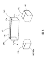
- FIG. 3 is an overall perspective view of the rectangular tubular slot liner 14 formed by the first manufacturing method shown in FIG. 2, and a perspective view in the vicinity of a convex end 141 and a concave end 142, which will be described later. It is the figure which wrote together with sectional drawing in the convex-shaped edge part 141 and the concave-shaped edge part 142.
- FIG. 3 is a perspective view of the entire rectangular tubular slot liner 14 as viewed from the direction in which the slot liner 14 is inserted into the stator core 1.
- a convex end portion 141 is formed on an end portion (a stator core insertion side end portion) 14a on the insertion side of the slot liner 14 into the stator core 1.
- a concave end portion 142 is formed at an end portion (segment coil insertion side end portion) 14b of the slot liner 14 opposite to the stator core insertion side end portion 14a.
- An arrow A shown in the vicinity of the convex end 141 indicates the insertion direction of the slot liner 14 into the stator core 1.
- An arrow B shown in the vicinity of the concave end 142 indicates the direction in which the segment coil 3 is inserted into the slot liner 14.
- the convex end portion 141 has a conical surface 141a for facilitating the insertion of the rectangular tubular slot liner 14 into the stator core 1.
- the conical surface 141 a is a slope whose apex of the conical surface faces the insertion direction into the stator core 1. Therefore, the outer peripheral length of the rectangular tubular slot liner 14 at the convex end 141 decreases from the segment coil insertion side end 14b toward the stator core insertion side end 14a.
- the conical surface 141a is inclined so that the convex end portion 141 is narrowed in the insertion direction into the stator core 1, the rectangular cylindrical slot liner 14 can be easily inserted into the slot 4.
- the coil space factor can be improved by reducing the thickness of the rectangular tubular slot liner 14, and thus the rotating electrical machine can be reduced in size and weight.
- the concave end 142 has a conical surface 142a for facilitating the insertion of the segment coil 3 into the rectangular tubular slot liner 14.
- the conical surface 142 a is an inclined surface in which the apex of the conical surface faces the insertion direction into the stator core 1. Therefore, the inner circumferential length of the rectangular tubular slot liner 14 at the concave end 142 increases from the stator core insertion side end 14a toward the segment coil insertion side end 14b.
- the conical surface 142a is inclined so that the inner diameter of the square cylindrical slot liner 14 at the concave end 142 increases in the direction opposite to the insertion direction of the segment coil 3, the segment coil 3 Can be easily inserted into the rectangular tubular slot liner 14.
- the coil space factor can be improved by increasing the cross-sectional area of the segment coil 3, so that the rotating electrical machine can be reduced in size and weight.
- the conical surface 141 a and the conical surface 142 a are cut surfaces formed by cutting with the rotary cutter 110.
- the convex end portion 141 corresponds to the roll cutter side cutting surface of the regular cut insulating paper 12 in FIG. 2, and the concave end portion 142 corresponds to the opposite cutting surface, and has a slope angle with respect to the slot liner insertion direction.
- the gradient angle 133 of the convex end portion 141 of the rectangular tubular slot liner 14 is defined as a first gradient angle
- the gradient 134 of the concave end portion 142 is defined as a second gradient angle.
- the first slope angle 133 is an angle formed between the conical surface 141a and the inner peripheral surface of the rectangular tubular slot liner 14, and as shown in FIG. 3, the rectangular tubular slot liner 14 is inserted in the slot liner insertion direction. Is the angle of the cross section of the convex end portion 141 when cut in parallel with.
- the second slope angle 134 is an angle formed between the conical surface 142a and the inner peripheral surface of the rectangular cylindrical slot liner 14, and as shown in FIG. 3, the rectangular cylindrical slot liner 14 is inserted in the slot liner insertion direction. Is the angle of the cross section of the concave end 142 when cut in parallel.
- the conical surface 141a is a conical surface for facilitating the insertion of the rectangular tubular slot liner 14 into the stator core 1. Therefore, the first gradient angle 133 is an acute angle.
- the conical surface 142a is a conical surface for facilitating the insertion of the segment coil 3 into the rectangular tubular slot liner 14. Therefore, the second gradient angle 134 is an obtuse angle.
- the first gradient angle 133 and the second gradient angle are different angles.
- the conical surface 141a is configured to face the outside of the rectangular tube slot liner 14 (inside the slot 4), thereby forming a rectangular tube shape.
- the slot liner 14 can be easily inserted into the stator core 1. Thereby, since the coil space factor can be improved as described above, the rotating electrical machine can be reduced in size and weight.
- the conical surface 142a is configured to face the inner side (segment coil 3 side) of the rectangular tube-shaped slot liner 14, whereby the segment coil 3. Can be easily inserted into the rectangular tubular slot liner 14.
- the first gradient angle 133 and the second gradient angle have a complementary angle relationship.
- FIG. 4 is a view showing a second manufacturing method of the slot liner of the present invention using shear cutting.
- the insulating paper fed from the insulating paper original fabric 10 is cut by a cutting blade 111 that moves perpendicularly to the insulating paper feed direction.
- the cut surfaces at both ends of the insulating paper (fixed insulating paper) 15 after being cut regularly are perpendicular to the feeding direction of the insulating paper. Therefore, after the standard cutting, for example, only the cutting surface far from the cutting blade 111 is trimmed by using the slide cutter 112 inclined with respect to the insulating paper feeding direction, so that the cutting surface inclined with respect to the insulating paper feeding direction.
- the fixed insulating paper 15 after trimming is formed into a rectangular tubular slot liner 17 through a bending process in the same manner as in the first manufacturing method shown in FIG.
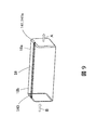
- FIG. 5 is a perspective view of the entire rectangular tube slot liner 17 formed by the second manufacturing method shown in FIG. 4 and a perspective view of the vicinity of the concave end 142 and the flat end 140 described later.
- FIG. A flat end 140 perpendicular to the direction of insertion into the stator core 1 is formed at the stator core insertion side end 17 a of the rectangular tubular slot liner 17.
- a concave end 142 is formed at the segment coil insertion side end 17 b of the rectangular tubular slot liner 17.
- the first gradient at the flat end 140 is 90 °.
- FIG. 6 is a diagram schematically showing an example of a method of bending the insulating paper that has been cut into regular lengths.
- the Roman numerals in FIG. 6 are numbers indicating the processing order.
- the fixed-length cut insulating paper 20 is conveyed onto the bottom bending jigs 22a and 22b, is pressed and bent by the pressing jig 21, and is loaded into the bottom bending jigs 22a and 22b (I). Thereafter, the bottom bending jigs 22a and 22b are overbended by moving in the direction of the central axis, thereby forming a predetermined bending angle (90 ° in this case) (II).
- the upper bending mandrel 23 is inserted (III), and the upper shoulder is overbended by the upper both shoulder bending jigs 24a and 24b (IV). After finishing the bending of the upper shoulder, the over-bended upper shoulders are spring-backed to form a rectangular tubular slot liner. The upper forming bending mandrel 23 is collected after the slot liner is formed and is used repeatedly.
- the results of verification trial production of stator cores using various slot liners will be described.
- the number of assembled stator cores is one in each of the examples and the comparative examples.
- three slot liners manufactured by the first and second manufacturing methods described above were used, and a total of six slot liners were used.
- the slot liner produced by the first manufacturing method is used, the first gradient angle 133 is set to 20 °, 45 °, and 70 °, respectively, and the second gradient angle 134 is set to 160 °. °, 135 °, and 110 °.
- the second gradient angle 134 is a complementary angle of the first gradient angle 133.
- the slot liner manufactured by the second manufacturing method is used, and the first gradient angles are all 90 °. Similarly to 3, it was set to 20 °, 45 °, and 70 °, respectively.
- the gradient angle was set by adjusting the blade edge angle of the rotary cutter 110 in FIG.
- the slope angle was set by adjusting the tilt angle of the slide cutter 112 in FIG.
- a conventional slot liner having first and second gradient angles of 90 ° was used as a comparative example.
- the slot liner used in the comparative example was manufactured by the second manufacturing method excluding the trimming process by the slide cutter 112.
- the slot liner insertion failure frequency is the number of insertion failures that occurred when the slot liners of the examples and comparative examples were inserted into the slot 4.
- the segment coil insertion failure frequency is the number of insertion failures that occur when the segment coil 3 is inserted into the slot liner of each of the examples and comparative examples inserted in the slot 4.
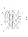
- FIG. 7 is a view showing a longitudinal cross-sectional configuration in the slot of the stator assembled in Example 2 described above, and shows the stator core innermost surface 31 as an upper portion in the drawing.
- the connecting portion 3a (see FIG. 8) of the segment coil 3 is on the convex end portion 141 side having the first slope 133 of the slot liner, and the folded portion 3b (see FIG. 8) has the second slope 134 of the slot liner. It arrange
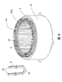
- FIG. 8 shows a perspective view of a stator 41 of a motor for a hybrid vehicle to which the present invention is applied, and a perspective view of a segment coil 3 before being inserted into the stator core 1.
- a stator 41 shown in FIG. 8 is a stator manufactured by a segment winding method having a high coil space factor to which the present invention is applied, and is fitted in a housing 44.
- the segment coil connecting portion 3a When the segment coil 3 is inserted into the stator core 1, the segment coil connecting portion 3a is inserted into the segment coil insertion side end portion 14b of the rectangular tubular slot liner 14 that has been inserted into the stator core 1 (slot 4). Therefore, as described above, in the segment coil 3 after being inserted into the stator core 1, the connecting portion 3a protrudes outward from the stator core insertion side end portion 14a, and the folded portion 3b protrudes outward from the segment coil insertion side end portion 14b. To do.
- the segment coil 3 after being inserted into the stator core 1 is bent at a connection portion 3a into a predetermined shape in order to connect the segment coils.
- the stator 41 shown in FIG. 8 is in a state where the connecting portion 3a is bent into a predetermined shape.
- the stator 41 shown in FIG. 8 is electrically connected after the segment coils are welded at the connection portion 3a.
- the insertion of the segment coil 3 into the slot liner 17 is prioritized over the insertion of the slot liner 17 into the stator core 1, so that the concave end portion is formed on the segment coil insertion side end portion 17 b. 142, and the convex end 141 is not provided on the stator core insertion side end 17a.
- the present invention is not limited to this.
- priority is given to facilitating the insertion work into the stator core 1 and the segment coil insertion side end 18b is not provided with the concave end 142, but the stator core insertion side end 18a.
- a convex end 141 may be provided. In this case, the stator core insertion side end 18 a becomes a convex end 141 having a first gradient, and the segment coil insertion side end 18 b becomes a flat end 140.
- a method using a slide cutter 113 for standard cutting instead of the rotary cutter 110 is applicable.
- the cut surfaces of the insulating paper 12a that has been cut into regular lengths are inclined with respect to the feeding direction at both end surfaces in the feeding direction generated by the cutting.
- laser cutting can also be applied to the method of cutting so that both end faces in the sending direction generated by cutting are inclined with respect to the sending direction.
- the insulating paper cutting surface is inclined by the slide cutter 112 as shown in FIG. 4, but the flat milling blade 114 is fed in the feeding direction as shown in FIG. It is possible to form a cut surface that is inclined with respect to the feeding direction by being applied to one end face or both end faces.
- the rectangular slot liners 14, 17, and 18 are formed by bending after the regular cut of the insulating paper original fabric 10.
- the method for forming the rectangular tube slot liner is not limited to this, and the insulating paper fed from the hoop-shaped insulating paper original 10 is formed into a rectangular tube slot liner shape by roll forming and then cut into a regular length.
- a method of inserting into the slot 4 can be considered.
- a disc saw or a metal saw is used for the regular cutting of the slot liner formed into a rectangular tube shape.
- the slot liner thus cut has a flat end 140.
- FIG. 12 is a diagram illustrating a method of forming the convex end portion 141 at the stator core insertion side end portion 19a.
- By tilting the flat milling blade 52 an inclination is formed on one side of the end portion of the slot liner.
- the slot liner holder 51 may be rotated and this operation repeated.
- the method shown in FIG. 13 is applicable to the concave processing of the segment coil insertion side end 19b.
- the intermediate product of the rectangular tubular slot liner 19 is inserted into a slot liner holder 53 having a circular inner surface slightly shorter than the slot liner circumferential length, thereby being spread and fixed in a cylindrical shape.
- the segment coil insertion side end portion 19b is processed into a concave shape by applying the rotary bar 54 to the segment coil insertion side end portion 19b of the slot liner 19 which is projected in a predetermined length from the end surface of the holder 53 and expands into a cylindrical shape.
- a slot liner having a rectangular cross section (cross section) cut along a plane perpendicular to the extending direction of the slot liner is used.
- a B-shaped slot liner whose cross section shown in FIG. 61 or an S-shaped slot liner 62 having a S-shaped cross section can be used.
- a space surrounded by a rectangular shape is present in two places above and below in the figure, and the segment coil 3 is inserted into this space in front of the drawing or in the depth direction. .
- the convex end portion 141 and the concave end portion 142 can be formed by the method for forming the convex end portion 141 and the concave end portion 142 used in the above-described embodiments.
- one surface 62a of both sides of the insulating paper before being formed into an S-shape is the upper side of two spaces surrounded by a rectangular shape when formed into an S-shape. Appears on the inner surface surrounding the space and appears on the outer surface surrounding the lower space.
- the other surface 62b is an outer surface surrounding the upper space of the two spaces enclosed in a rectangular shape when formed into an S-shape. Appears on the inner surface surrounding the lower space.
- the conical surface 142a of the concave end 142 has a uniform inclination angle from the inner peripheral surface to the outer peripheral surface of the slot liner 14 formed into a rectangular shape.
- the present invention is not limited to this.
- FIGS. 15B to 15F various modifications can be made to the shape of the conical surface 142a.
- FIGS. 15A to 15F are views showing a section (longitudinal section) cut along a plane parallel to the extending direction of the slot liner in the vicinity of the end portion on the segment coil insertion side.
- the conical surface 142a may be partially provided on the inner peripheral side of the slot liner 151 after being formed into a rectangular shape.
- a conical surface 142a is partially provided on the inner peripheral side of the slot liner 152 after molding, and a conical surface 142b having an inclination angle different from that of the conical surface 142a is provided from the left end of the conical surface 142a in the drawing.
- a plurality of conical surfaces may be provided.
- a surface 142c obtained by chamfering the outer peripheral end of the slot liner 153 may be provided.
- the concave end 142 may be formed by appropriately combining these conical surfaces 142a to 142e.
- the second gradient angle 134 in each of these conical surfaces 142a to 142e is defined as shown. That is, the second gradient angle 134 is defined as an angle formed between the tangent line of each cone surface at the intersection of each cone surface 142a, 142d, 142e and the slot liner inner surface and the slot liner inner surface.
- the shape of the outer periphery in the vicinity of the concave end 142 is not limited to the shape of the surface 142c shown in FIG. 15 (d), and may be a shape composed of a plurality of planes with different inclination angles, and may be a curved surface. A configured shape may be used.
- the aramid / PET / aramid three-layer insulating paper is used as the slot liner.
- the present invention is not limited to this, and a sheet-like insulating member made of another material is used. You may use suitably. In addition, you may combine each Example and modification which were mentioned above, respectively.
- the present invention is not limited to the above-described embodiment, and includes a core provided with a slot communicating in the axial direction, a winding provided in the slot, and between the slot and the winding.
- the insulating member includes the first conical surface provided on the slot insertion side and / or the second conical surface provided on the winding insertion side as the core shaft. It includes a rotating electrical machine of various structures characterized by being provided at an end portion in the direction.
- stator core 1 stator core, 2, 14, 17, 18 slot liner, 3 stator coil (segment coil), 4 slots, 14a stator core insertion side end, 14b segment coil insertion side end, 41 stator, 133 gradient angle (first gradient angle) ), 134 slope angle (second slope angle), 140 flat end portion, 141 convex end portion, 141a conical surface, 142 concave end portion, 142a conical surface
Landscapes
- Engineering & Computer Science (AREA)
- Power Engineering (AREA)
- Insulation, Fastening Of Motor, Generator Windings (AREA)
- Manufacture Of Motors, Generators (AREA)
Abstract
コイル占積率を向上させて回転電機の小型化、軽量化を図る。 本発明による回転電機は、軸方向に連通するスロットが設けられたコアと、スロット内に設けられた巻線と、スロットと巻線との間に設けられた絶縁部材とを備える回転電機において、絶縁部材は、スロットへの挿入側に設けた第1の錐面、および/または、巻線の挿入側に設けた第2の錐面がコア軸方向の端部に設けられていることを特徴とする。
Description
本発明は、回転電機に関する。
近年普及しつつあるハイブリッド自動車や電気自動車においては、動力源のモータの小型、軽量化の要求が強い。小型化の一手段として、回転電機ステータコイルのスロット内の導体占積率を上げて出力密度を上げる考え方がある。これを実現するために、従来行われていた連続したエナメル絶縁線をスロットに組込む構造に変えて、コイル導体を多数の所定形状に曲げ成型されたセグメントコイルに分割してスロットに組込み、その後各セグメント導体を電気的に接続する、いわゆるセグメント巻線方式が用いられている。
一方、ハイブリッド自動車、電気自動車では、インバータによるモータ駆動が前提となり、モータ駆動インバータの高電圧化に伴い、セグメント巻線方式のステータコイルでは、ステータコアおよびコイル相間の電気絶縁を確保するために、スロット内のセグメント巻線には、絶縁紙(スロットライナ)がセグメントコイル/ステータコア間および異相コイル間に挿入される(特許文献1参照)。
しかし、スロットライナの介在により、ステータコイル組立においては、スロット内へのスロットライナの挿入、およびスロットライナ内へのセグメントコイルの挿入時にスロットライナが損傷し絶縁不良を起こしやすくなるおそれがある。また、挿入ギャップを設ける必要があるため、コイル占積率(スロット内におけるコイル導体断面積とスロット断面積の比)を向上させ難かった。
本発明による回転電機は、回転電機のスロットと巻線との間に設けられた絶縁部材は、スロットへの挿入側に設けた第1の錐面、および/または、巻線の挿入側に設けた第2の錐面がコア軸方向の端部に設けられていることを特徴とする。
本発明によれば、コイル占積率が向上するので、回転電機の小型化、軽量化が図れる。
本発明による回転電機の一実施の形態を説明する。以下、定格運転電圧300Vdc-電流400Armsのセグメント巻線方式適用の3相12極ハイブリッド自動車駆動モータの、外径245mm、内径200mm、スロット数72の35A300相当の打ち抜き電磁鋼板による積厚90mmの積層コアで構成されるステータコアを対象とした一実施の形態、および、比較例により、本発明を説明する。
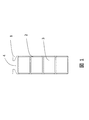
本実施の形態、および、比較例に用いたハイブリッド自動車駆動モータのステータコアにおけるスロット内構成を図1に示す。ステータコイル(巻線)には、平角エナメル絶縁線によるセグメントコイル3が用いられる。スロット4は、平角セグメントコイル3を密に収納させるために、幅一定の略矩形形状となり、ステータコイルを形成するセグメントコイル3が4本挿入される。
スロットライナ2は、対ステータコア1との絶縁に加え、異相コイル間の絶縁に用いられる絶縁部材であり、図1の紙面奥行き方向であるステータコア1のコア軸方向に延在するようにスロット4内に配設される。スロットライナ端部が平坦な従来のスロットライナを用いることを前提に、短辺2.4mm、長辺3.3mm、コーナー面取り半径0.3mmの平角導体上に、厚さ0.05mmのポリアミドイミド絶縁層が被覆された平角絶縁線が用いられ、スロットライナには、アラミド/PET/アラミドの3層構造の厚さ0.17mmの絶縁紙を四角筒状に成形したものが用いられる。スロットの幅、平行部深さおよびスロット内断面積は、それぞれ4.14mm、12.0mm、52.0mm2であり、この構成におけるコイル占積率は60.3%となる。
このステータコアに対し、本発明を適用し、高コイル占積率のステータコアが製造可能か検証した。検証試作では、短辺2.53mm、長辺3.6mm、コーナー面取り半径0.3mmの平角導体上に、厚さ0.05mmのポリアミドイミド絶縁層が被覆された平角絶縁線も用いた。スロットライナの配置は図1と同様とし、同一構成、厚さの絶縁紙からスロットライナを成形した。このスロット内構成でのコイル占積率は、69.5%と従来構成に対し、約10%コイル占積率がアップする。
検証試作では、試作適用ステータコアサイズの変更なしに、自動組立ラインにおいて、上記平角絶縁導体によるセグメントコイルと本発明によるスロットライナで構成されるステータコアの組立性を比較検討した。具体的には、スロットライナのスロットへの挿入、セグメントコイルのスロットライナへの挿入における挿入不良発生回数を比較することでステータコア製造可能性を評価した。
スロットライナ長は96mmとし、ステータコアとセグメントコイル間の沿面放電防止層を設けるために、コアスロット両端面から3mmスロットライナがはみ出す構成とした。
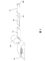
図2は、スロットライナ14の製造工程の一例を示す図である。図2に示すように、スロットライナ14の製造工程では、所定幅に裁断されたフープ状の絶縁紙原反10からシート状の絶縁紙を引き出し、ロータリーカッター110により所定長さの絶縁紙12を切断、曲げ成形することでスロットライナ14が製作されている。ロータリーカッター110を絶縁紙の定尺切断に用いることで、切断面は絶縁紙の送り出し方向に対し傾斜する。定尺切断後の絶縁紙12は、折り曲げ加工を経て角筒状のスロットライナ14に成形される。折り曲げ加工される絶縁紙13に示される破線は、折り目を表している。
図3は、図2に示した第1の製造方法で形成された角筒状スロットライナ14の全体の斜視図と、後述する凸状端部141および凹状端部142の近傍の斜視図と、凸状端部141および凹状端部142における断面図とを併記した図である。なお、図3の角筒状スロットライナ14の全体の斜視図は、角筒状スロットライナ14をスロットライナ14のステータコア1への挿入方向から見た斜視図である。
スロットライナ14のステータコア1への挿入側の端部(ステータコア挿入側端部)14aには、凸状端部141が形成されている。スロットライナ14のステータコア挿入側端部14aとは反対側の端部(セグメントコイル挿入側端部)14bには凹状端部142が形成されている。凸状端部141の近傍に図示される矢印Aは、スロットライナ14のステータコア1への挿入方向を示している。凹状端部142の近傍に図示される矢印Bは、セグメントコイル3のスロットライナ14への挿入方向を示している。
凸状端部141は、角筒状スロットライナ14のステータコア1への挿入を容易化するための錐面141aを有する。錐面141aは、錐面の頂点がステータコア1への挿入方向を向いた斜面である。そのため、凸状端部141における角筒状スロットライナの14の外周長は、セグメントコイル挿入側端部14bからステータコア挿入側端部14aに向かうにつれて小さくなる。このように、ステータコア1への挿入方向に向かって凸状端部141が窄まるように錐面141aが傾斜しているので、角筒状スロットライナ14のスロット4への挿入が容易となる。これにより、角筒状スロットライナ14をスロット4へ挿入する際の角筒状スロットライナ14の破損が防止できる。したがって、たとえば角筒状スロットライナ14の厚さを薄くすることによってコイル占積率を向上できるので、回転電機の小型化、軽量化が図れる。
凹状端部142は、セグメントコイル3の角筒状スロットライナ14への挿入を容易化するための錐面142aを有する。錐面142aは、錐面の頂点がステータコア1への挿入方向を向いた斜面である。そのため、凹状端部142における角筒状スロットライナの14の内周長は、ステータコア挿入側端部14aからセグメントコイル挿入側端部14bに向かうにつれて大きくなる。このように、セグメントコイル3の挿入方向とは反対の方向に向かうにつれて凹状端部142における角筒状スロットライナの14の内径が大きくなるように錐面142aが傾斜しているので、セグメントコイル3の角筒状スロットライナ14への挿入が容易となる。これにより、セグメントコイル3を角筒状スロットライナ14へ挿入する際の角筒状スロットライナ14の破損が防止できる。したがって、たとえばセグメントコイル3の断面積を増やすことによってコイル占積率を向上できるので、回転電機の小型化、軽量化が図れる。
なお、錐面141aおよび錐面142aは、ロータリーカッター110による切断によって形成された切断面である。凸状端部141は、図2における定尺切断絶縁紙12のロールカッター側切断面に、凹状端部142は、その反対切断面にそれぞれ相当し、スロットライナ挿入方向に対し勾配角を有する。ここで、角筒状スロットライナ14の凸状端部141の勾配角133を第1勾配角と定義し、凹状端部142の勾配134を第2勾配角と定義する。
なお、第1勾配角133は、錐面141aと、角筒状スロットライナ14の内周面とのなす角度であって、図3に示すように、角筒状スロットライナ14をスロットライナ挿入方向と平行に切断したときの凸状端部141の断面の角度である。また、第2勾配角134は、錐面142aと、角筒状スロットライナ14の内周面とのなす角度であって、図3に示すように、角筒状スロットライナ14をスロットライナ挿入方向と平行に切断したときの凹状端部142の断面の角度である。
上述したように、錐面141aは、角筒状スロットライナ14のステータコア1への挿入を容易化するための錐面である。そのため、第1勾配角133は、鋭角となる。同様に、錐面142aは、セグメントコイル3の角筒状スロットライナ14への挿入を容易化するための錐面である。そのため、第2勾配角134は、鈍角となる。このように第1勾配角133と第2勾配角とは異なる角度となる。
すなわち、第1勾配角133を鋭角とし、角筒状に成形した際に、錐面141aが角筒状スロットライナ14の外側(スロット4の内側)を向くように構成することで、角筒状スロットライナ14のステータコア1への挿入が容易となる。これにより、上述したようにコイル占積率を向上できるので、回転電機の小型化、軽量化が図れる。
また、第2勾配角134を鈍角とし、角筒状に成形した際に、錐面142aが角筒状スロットライナ14の内側(セグメントコイル3側)を向くように構成することで、セグメントコイル3の角筒状スロットライナ14への挿入が容易となる。これにより、上述したようにコイル占積率を向上できるので、回転電機の小型化、軽量化が図れる。
なお、ロータリーカッター110のように、一度の切断で錐面141aおよび錐面142aが形成される場合、第1勾配角133と第2勾配角とは、補角の関係となる。
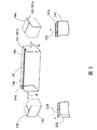
図4は、シャー切断を用いた本発明スロットライナの第2の製造方法を示す図である。図4に示す第2の製造方法では、絶縁紙原反10から送り出される絶縁紙が、絶縁紙送り出し方向に対し垂直に移動する切断刃111により定尺切断される。この場合、定尺切断された後の絶縁紙(定尺絶縁紙)15の両端の切断面は、絶縁紙送り出し方向に対し垂直となる。そこで、定尺切断後に、たとえば切断刃111から遠い方の切断面のみを、絶縁紙送り出し方向に対し傾斜したスライドカッター112を用いてトリミングすることで、絶縁紙送り出し方向に対して傾斜した切断面を形成する。トリミングが終了した定尺絶縁紙15は、図2で示した第1の製造方法と同様に折り曲げ加工を経て角筒状スロットライナ17に成形される。
図5は、図4に示した第2の製造方法で形成された角筒状スロットライナ17の全体の斜視図と、凹状端部142および後述する平坦端部140の近傍の斜視図とを併記した図である。角筒状スロットライナ17のステータコア挿入側端部17aには、ステータコア1への挿入方向に対して垂直な平坦端部140が形成されている。角筒状スロットライナ17のセグメントコイル挿入側端部17bには凹状端部142が形成されている。なお、角筒状スロットライナ17では、平坦端部140における第1勾配は90°である。
図6は、定尺切断された絶縁紙の折り曲げ加工方法の一例を模式的に示した図である。図6におけるローマ数字は、加工順序を示す数字である。定尺切断絶縁紙20は、底部曲げ治具22a,22b上に搬送され、押付治具21により押し曲げられて底部曲げ治具22a,22b内に装填される(I)。その後、底部曲げ治具22a,22bの中心軸方向への移動によってオーバーベンドされることで、所定の曲げ角度(この場合は90°)に成形される(II)。
底部形成終了後、上部曲げマンドレル23が挿入され(III)、上部両肩部曲げ治具24a,24bにより上部肩部のオーバーベンド加工がなされる(IV)。上部肩部の曲げ加工終了後、オーバーベンドされた上部両肩部がスプリングバックして、角筒形状のスロットライナが成形される。上部形成曲げマンドレル23は、スロットライナの成形後に回収され、繰返し使用される。
---検証試作結果について---
以下に示す表1を参照して、種々のスロットライナを用いたステータコアの検証試作結果について説明する。検証試作では、各実施例、比較例ともステータコア組立台数は、1台とした。本発明を適用した実施例には、上述した第1および第2の製造方法で製作したスロットライナをそれぞれ3種、合計6種のスロットライナを用いた。本発明を適用した実施例1~3では、第1の製造方法で制作したスロットライナを用い、第1勾配角133をそれぞれ20°、45°、70°とし、第2勾配角134をそれぞれ160°、135°、110°とした。なお、第2勾配角134は第1勾配角133の補角となっている。
以下に示す表1を参照して、種々のスロットライナを用いたステータコアの検証試作結果について説明する。検証試作では、各実施例、比較例ともステータコア組立台数は、1台とした。本発明を適用した実施例には、上述した第1および第2の製造方法で製作したスロットライナをそれぞれ3種、合計6種のスロットライナを用いた。本発明を適用した実施例1~3では、第1の製造方法で制作したスロットライナを用い、第1勾配角133をそれぞれ20°、45°、70°とし、第2勾配角134をそれぞれ160°、135°、110°とした。なお、第2勾配角134は第1勾配角133の補角となっている。
本発明を適用した実施例4~6では、第2の製造方法で製作したスロットライナを用い、第1勾配角が全て90°であるが、セグメントコイル挿入側の第2勾配を実施例1~3と同様にそれぞれ20°、45°、70°とした。
なお、実施例1~3に用いるスロットライナでは、図2のロータリーカッター110の刃先角度を調整することで勾配角を設定した。また、実施例4~6に用いるスロットライナでは、図4のスライドカッター112の傾斜角を調整することで勾配角を設定した。
比較例には、第1、第2勾配角度がともに90°である従来のスロットライナを用いた。比較例に用いたスロットライナは、スライドカッター112によるトリミング工程を除いた第2の製造方法により製作した。
表1における、スロットライナ挿入不良回数とは、スロット4へ各実施例および比較例のスロットライナを挿入する際に発生した挿入不良の回数である。また、セグメントコイル挿入不良回数とは、スロット4に挿入されている各実施例および比較例のスロットライナへセグメントコイル3を挿入する際に発生した挿入不良の回数である。
表1に示すように、本発明を適用した全ての実施例1~6では、スロットライナおよびセグメントコイルの挿入不良が発生せず、本発明を適用することで高コイル占積率のステータコアを組立可能であることが判明した。これに対し、比較例では、スロット4へスロットライナを挿入する場合には、挿入不良が発生しなかったが、スロットライナへセグメントコイル3を挿入する場合には、セグメントコイルの挿入本数の増大に伴いスロットライナの圧潰が発生し、多回のセグメントコイル挿入不良が発生した。このことより、従来の切断端面が平坦な(第1、第2勾配角度が90°である)スロットライナでは、高コイル占積率ステータコイルの製造が困難であることが明らかとなった。

図7は、上述した実施例2で組み立てられたステータのスロット内縦断面構成を示す図であり、ステータコア最内面31を図示上方として示したものある。セグメントコイル3の接続部3a(図8参照)は、スロットライナの第1勾配133を有する凸状端部141側に、折返し部3b(図8参照)は、スロットライナの第2勾配134を有する凹状端部142側にそれぞれ配置される。
図8は、本発明を適用したハイブリッド自動車用モータのステータ41の斜視図、および、ステータコア1へ挿入する前のセグメントコイル3の斜視図を併記した図である。図8に示したステータ41は、本発明を適用した高コイル占積率を有するセグメント巻線方式で製作されたステータであり、ハウジング44に嵌合されている。
ステータコア1へセグメントコイル3を挿入する際には、ステータコア1(スロット4)へ挿入済みの角筒状スロットライナ14のセグメントコイル挿入側端部14bへセグメントコイルの接続部3aを挿入する。そのため、上述したように、ステータコア1へ挿入後のセグメントコイル3は、接続部3aがステータコア挿入側端部14aよりも外側に突出し、折返し部3bがセグメントコイル挿入側端部14bよりも外側に突出する。
ステータコア1へ挿入後のセグメントコイル3は、セグメントコイル同士の接続のために、接続部3aが所定形状に曲げ加工される。図8に示すステータ41は、接続部3aが所定形状に曲げ加工された状態のものである。なお、図8に示すステータ41は、この後、セグメントコイル同士が接続部3aで溶接されて、電気的に接続される。
上述した実施例の角筒状スロットライナ17では、セグメントコイル3のスロットライナ17のへ挿入をスロットライナ17のステータコア1への挿入よりも優先させたため、セグメントコイル挿入側端部17bに凹状端部142を設け、ステータコア挿入側端部17aには凸状端部141を設けていない。しかし、本発明はこれに限定されない。たとえば、図9に示すスロットライナ18のように、ステータコア1への挿入作業の容易化を優先させて、セグメントコイル挿入側端部18bに凹状端部142を設けずに、ステータコア挿入側端部18aへ凸状端部141を設けてもよい。この場合、ステータコア挿入側端部18aは、第1勾配を有する凸状端部141となり、セグメントコイル挿入側端部18bは、平坦端部140となる。
本発明で用いるスロットライナ加工方法としては、図10に示すように、ロータリーカッター110の代わりにスライドカッター113を定尺切断に用いる方法が適用可能である。この場合、定尺切断された絶縁紙12aの切断面は、切断によって生じた送り出し方向の両端面とも送り出し方向に対し傾斜する。このように、切断によって生じた送り出し方向の両端面とも送り出し方向に対し傾斜するように切断する手法には、レーザー切断も適用可能である。
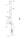
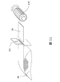
一般的なシャー切断で切断する場合、上述した実施例では図4に示すようにスライドカッター112により絶縁紙切断面に傾斜を付けたが、図11に示すように平フライス刃114を送り出し方向の一方の端面あるいは両端面に当てることで送り出し方向に対し傾斜した切断面を形成することが可能である。
また、上述した実施例では、角筒状スロットライナ14,17,18を絶縁紙原反10の定尺切断後に曲げ加工により成形した。しかし、角筒状スロットライナの成形方法としてはこれに限定されず、フープ状の絶縁紙原反10から送り出される絶縁紙をロールフォーミングにより角筒状スロットライナの形状に成形後に定尺切断し、スロット4に挿入する手法が考えられる。角筒状に成形されたスロットライナの定尺切断には、ディスクソーあるいはメタルソーが用いられるが、いずれにしても切断されたスロットライナは平坦端部140を有することになる。
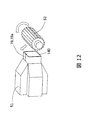
この手法で製作されるスロットライナ19に本発明を適用するには、平坦端部の加工が必要になる。図12は、ステータコア挿入側端部19aに凸状端部141を形成する手法を示す図である。ロールフォーミングにより角筒状スロットライナの形状に成形後に定尺切断されたスロットライナ19の中間品をスロットライナ・ホルダ51で把持し、所定長さで端部が突出されたステータコア挿入側端部19aに平フライス刃52を斜行させることでスロットライナ端部の一辺に傾斜を形成する。多辺を傾斜加工する場合は、スロットライナ・ホルダ51を回転させ、この動作を繰り返せば良い。
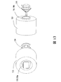
セグメントコイル挿入側端部19bの凹状化加工には、図13に示す手法が適用可能である。角筒状スロットライナ19の中間品は、スロットライナ周長より若干短い円周の円形内面を有するスロットライナ・ホルダ53に挿入されることで、円筒状に広がり固定される。ホルダ53端面から所定長さで突出された円筒状に広がったスロットライナ19のセグメントコイル挿入側端部19bに、ロータリーバー54を当てることで、セグメントコイル挿入側端部19bを凹状に加工する。
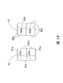
上述の説明では、スロットライナの延在方向に垂直な面で切断した断面(横断面)が矩形のスロットライナを用いたが、図14に示す横断面がB字状であるB字状スロットライナ61、あるいは、横断面がS字状であるS字状スロットライナ62を用いることができる。B字状スロットライナ61およびS字状スロットライナ62では、矩形状に囲まれた空間が図示上下の2箇所に存在し、この空間に図示紙面の手前または奥行き方向にセグメントコイル3が挿入される。
B字状スロットライナ61では、B字状に成形前の絶縁紙の両面のうち、一方の面61aは、B字状に成形した際にB字状の外周に現れて、スロット4と接触する。また、B字状に成形前の絶縁紙の両面のうち、他方の面61bは、B字状に成形した際にB字状の内周に現れて、セグメントコイル3と接触する。そのため、上述した各実施例に用いた凸状端部141および凹状端部142の形成方法によって、凸状端部141および凹状端部142を形成できる。
S字状スロットライナ62では、S字状に成形前の絶縁紙の両面のうち、一方の面62aは、S字状に成形した際に矩形状に囲まれた2つの空間のうち、上側の空間を囲む内側の面に現れるとともに、下側の空間を囲む外側の面に現れる。また、S字状に成形前の絶縁紙の両面のうち、他方の面62bは、S字状に成形した際に矩形状に囲まれた2つの空間のうち、上側の空間を囲む外側の面に現れるとともに、下側の空間を囲む内側の面に現れる。そのため、絶縁紙を定尺切断後にS字状の形状にスロットライナを成形する場合は、スロット4およびセグメントコイル3との接触面に対応して傾斜面を設ける必要があり、スロットライナ成形、定尺切断後に端部を凸状、凹状に加工する手法の適用が望ましい。
上述した各実施例では、図15(a)に示すように、凹状端部142の錐面142aは、矩形状に成形後のスロットライナ14の内周面から外周面まで、傾斜角度が一様であるが、本発明はこれに限定されない。たとえば、図15(b)~(f)に示すように、錐面142aの形状には様々な変形例が挙げられる。なお、図15(a)~(f)は、スロットライナの延在方向と平行面で切断した断面(縦断面)をセグメントコイル挿入側端部の近傍について示す図である。
たとえば、図15(b)に示すように、錐面142aを矩形状に成形後のスロットライナ151の内周側に部分的に設けてもよく、図15(c)に示すように、矩形状に成形後のスロットライナ152の内周側に錐面142aを部分的に設け、錐面142aの図示左側端部から錐面142aとは異なる傾斜角度の錐面142bを設けるなど、異なる傾斜角度の錐面を複数設けてもよい。また、図15(d)に示すように、スロットライナ153の外周側端部を面取りした面142cを設けてもよい。また、図15(e)や図15(f)に示すように、各ストッロライナ154,155の錐面142d,142eを曲面で構成してもよい。また、これらの各錐面142a~142eを適宜組み合わせることで凹状端部142を形成してもよい。
なお、図15では、これらの各錐面142a~142eにおける第2勾配角134を図示のように定義を示している。すなわち、第2勾配角134は、各錐面142a,142d,142eとスロットライナ内面との交点における各錐面の接線と、スロットライナ内面となす角度で定義される。また、本発明において、凹状端部142近傍の外周の形状は、図15(d)に示した面142cの形状に限らず、異なる傾斜角度の複数の平面で構成された形状でもよく、曲面で構成された形状でもよい。
また、上述の説明では、スロットライナとして、アラミド/PET/アラミドの3層構造の絶縁紙を用いたが、本発明はこれに限定されず、他の材料で構成されるシート状の絶縁部材を適宜用いてもよい。なお、上述した各実施例および変形例は、それぞれ組み合わせてもよい。
なお、本発明は、上述した実施の形態のものに何ら限定されず、軸方向に連通するスロットが設けられたコアと、スロット内に設けられた巻線と、スロットと巻線との間に設けられた絶縁部材とを備える回転電機において、絶縁部材は、スロットへの挿入側に設けた第1の錐面、および/または、巻線の挿入側に設けた第2の錐面がコア軸方向の端部に設けられていることを特徴とする各種構造の回転電機を含むものである。
1 ステータコア、2,14,17,18 スロットライナ、3 ステータコイル(セグメントコイル)、4 スロット、14a ステータコア挿入側端部、14b セグメントコイル挿入側端部、41 ステータ、133 勾配角(第1勾配角)、134 勾配角(第2勾配角)、140 平坦端部、141 凸状端部、141a 錐面、142 凹状端部、142a 錐面
Claims (6)
- 軸方向に連通するスロットが設けられたコアと、前記スロット内に設けられた巻線と、前記スロットと前記巻線との間に設けられた絶縁部材とを備える回転電機において、
前記絶縁部材は、前記スロットへの挿入側に設けた第1の錐面、および/または、前記巻線の挿入側に設けた第2の錐面が前記コア軸方向の端部に設けられていることを特徴とする回転電機。 - 請求項1に記載の回転電機において、
前記絶縁部材は、シート状の絶縁物が筒状に曲げられ、前記第1および前記第2の錐面が設けられた部材であり、
前記絶縁部材の前記スロットへの挿入を容易化するための前記第1の錐面と、前記絶縁部材の内周面とのなす角度は、前記巻線の前記絶縁部材への挿入を容易化するための前記第2の錐面と、前記絶縁部材の内周面とのなす角度と異なることを特徴とする回転電機。
回転電機。 - 請求項2に記載の回転電機において、
前記絶縁部材の前記スロットへの挿入を容易化するための前記第1の錐面は、前記スロット側に向かって傾斜しており、
前記巻線の前記絶縁部材への挿入を容易化するための前記第2の錐面は、前記巻線側に向かって傾斜していることを特徴とする回転電機。 - 請求項3に記載の回転電機において、
前記巻線は、接続部と折返し部とを有する複数のセグメント導体が前記接続部で接続された巻線であり、
前記絶縁部材の前記スロットへの挿入を容易化するための前記第1の錐面は、前記コア軸方向の前記接続部側に配設され、
前記巻線の前記絶縁部材への挿入を容易化するための前記第2の錐面は、前記コア軸方向の前記折返し部側に配設されることを特徴とする回転電機。 - 請求項1に記載の回転電機において、
前記絶縁部材は、シート状の絶縁物が筒状に曲げられ、前記絶縁部材の前記スロットへの挿入を容易化するための前記第1、または、前記巻線の前記絶縁部材への挿入を容易化するための前記第2の錐面が設けられた部材であり、
前記絶縁部材に前記絶縁部材の前記スロットへの挿入を容易化するための前記第1の錐面が設けられている場合、前記第1の錐面は、前記スロット側に向かって傾斜しており、 前記絶縁部材に前記巻線の前記絶縁部材への挿入を容易化するための前記第2の錐面が設けられている場合、前記第2の錐面は、前記巻線側に向かって傾斜していることを特徴とする回転電機。 - 請求項5に記載の回転電機において、
前記巻線は、接続部と折返し部とを有する複数のセグメント導体が前記接続部で接続された巻線であり、
前記絶縁部材に前記絶縁部材の前記スロットへの挿入を容易化するための前記第1の錐面が設けられている場合、前記第1の錐面は、前記コア軸方向の前記接続部側に配設され、
前記絶縁部材に前記巻線の前記絶縁部材への挿入を容易化するための前記第2の錐面が設けられている場合、前記第2の錐面は、前記コア軸方向の前記折返し部側に配設されることを特徴とする回転電機。
Priority Applications (3)
| Application Number | Priority Date | Filing Date | Title |
|---|---|---|---|
| US14/910,447 US10230281B2 (en) | 2013-08-08 | 2014-05-28 | Rotating electrical machine |
| CN201480043911.0A CN105453388B (zh) | 2013-08-08 | 2014-05-28 | 旋转电机 |
| EP14835348.5A EP3032710B1 (en) | 2013-08-08 | 2014-05-28 | Rotating electrical machine |
Applications Claiming Priority (2)
| Application Number | Priority Date | Filing Date | Title |
|---|---|---|---|
| JP2013-165181 | 2013-08-08 | ||
| JP2013165181A JP6049566B2 (ja) | 2013-08-08 | 2013-08-08 | 回転電機 |
Publications (1)
| Publication Number | Publication Date |
|---|---|
| WO2015019685A1 true WO2015019685A1 (ja) | 2015-02-12 |
Family
ID=52461032
Family Applications (1)
| Application Number | Title | Priority Date | Filing Date |
|---|---|---|---|
| PCT/JP2014/064047 Ceased WO2015019685A1 (ja) | 2013-08-08 | 2014-05-28 | 回転電機 |
Country Status (5)
| Country | Link |
|---|---|
| US (1) | US10230281B2 (ja) |
| EP (1) | EP3032710B1 (ja) |
| JP (1) | JP6049566B2 (ja) |
| CN (1) | CN105453388B (ja) |
| WO (1) | WO2015019685A1 (ja) |
Cited By (2)
| Publication number | Priority date | Publication date | Assignee | Title |
|---|---|---|---|---|
| WO2017190943A1 (de) * | 2016-05-02 | 2017-11-09 | Robert Bosch Gmbh | Verfahren und vorrichtung zum herstellen eines isolationselements |
| US20230253849A1 (en) * | 2020-08-20 | 2023-08-10 | Atop S.P.A. | Stator, apparatus and method for peparing a pre-shaped insulator |
Families Citing this family (13)
| Publication number | Priority date | Publication date | Assignee | Title |
|---|---|---|---|---|
| WO2017047247A1 (ja) * | 2015-09-17 | 2017-03-23 | 日立オートモティブシステムズ株式会社 | 回転電機 |
| US11183898B2 (en) * | 2016-07-08 | 2021-11-23 | Hitachi Industrial Equipment Systems Co., Ltd. | Rotary electric machine and manufacturing method for rotary electric machine |
| JP6389501B2 (ja) * | 2016-11-30 | 2018-09-12 | 公明 岩谷 | 回転機用コイル及び回転機 |
| JP7218180B2 (ja) * | 2017-01-16 | 2023-02-06 | 本田技研工業株式会社 | 絶縁部材、回転電機のステータおよび回転電機 |
| DE102017208566A1 (de) * | 2017-05-19 | 2018-11-22 | Mahle International Gmbh | Elektrische Maschine, insbesondere für ein Fahrzeug |
| DE102017208550A1 (de) * | 2017-05-19 | 2018-11-22 | Mahle International Gmbh | Elektrische Maschine, insbesondere für ein Fahrzeug |
| CN111837317B (zh) * | 2018-03-23 | 2023-05-30 | 株式会社爱信 | 定子的制造方法、定子的制造装置以及定子 |
| FR3082372B1 (fr) * | 2018-06-07 | 2022-06-03 | Leroy Somer Moteurs | Stator de machine electrique tournant |
| CN108631525B (zh) * | 2018-06-29 | 2023-09-26 | 江苏本格自动化科技有限公司 | 一种快速成型的压纸料库 |
| JP7181781B2 (ja) * | 2018-12-10 | 2022-12-01 | 株式会社Soken | 回転電機、電力変換装置及び回転電機の製造方法 |
| CN114450870A (zh) * | 2019-09-23 | 2022-05-06 | 卡诺科技公司 | 包括具有矩形横截面的线圈元件的分数槽电动马达 |
| CN111633127B (zh) * | 2020-06-08 | 2022-04-05 | 哈尔滨电气动力装备有限公司 | 湿绕组电机转子槽衬弯形工具 |
| JP7195358B2 (ja) * | 2021-03-17 | 2022-12-23 | 本田技研工業株式会社 | ステータ及びステータの製造方法 |
Citations (6)
| Publication number | Priority date | Publication date | Assignee | Title |
|---|---|---|---|---|
| JPS471988U (ja) * | 1971-01-21 | 1972-08-22 | ||
| JPS6254551U (ja) * | 1985-05-31 | 1987-04-04 | ||
| JP2002165421A (ja) | 1998-05-25 | 2002-06-07 | Denso Corp | 車両用交流発電機の固定子及びその製造方法 |
| JP2003070201A (ja) * | 2001-08-23 | 2003-03-07 | Toyota Motor Corp | 回転電機のステータおよびその製造方法 |
| JP2003088028A (ja) * | 2001-09-11 | 2003-03-20 | Moric Co Ltd | 回転電気機器の電機子のインシュレータ |
| JP2013009566A (ja) * | 2011-06-27 | 2013-01-10 | Asmo Co Ltd | ステータの製造方法、ステータ及びモータ |
Family Cites Families (13)
| Publication number | Priority date | Publication date | Assignee | Title |
|---|---|---|---|---|
| US4247978A (en) * | 1979-01-04 | 1981-02-03 | General Electric Company | Methods of making slot liners and stator assemblies including same |
| JPS6086476U (ja) * | 1983-11-17 | 1985-06-14 | 旭大隈産業株式会社 | 塗装装置の警告装置 |
| JPH0521954Y2 (ja) * | 1986-08-20 | 1993-06-04 | ||
| DE3721423A1 (de) * | 1987-06-29 | 1989-01-19 | Gaemmerler Hagen | Schneidvorrichtung fuer mindestens zweilagige flaechengebilde, insbesondere papierprodukte |
| EP0961386B1 (en) | 1998-05-25 | 2003-01-02 | Denso Corporation | Stator of ac generator for vehicle |
| JP3609649B2 (ja) * | 1999-06-29 | 2005-01-12 | 三洋電機株式会社 | ブラシレスdcモータ及びこのモータを用いた冷媒圧縮機 |
| KR101070997B1 (ko) * | 2009-11-03 | 2011-10-06 | 뉴모텍(주) | 압축기용 모터의 스테이터 |
| JP5482121B2 (ja) * | 2009-11-10 | 2014-04-23 | 株式会社富士通ゼネラル | 回転電機の固定子 |
| US8558427B2 (en) * | 2011-01-31 | 2013-10-15 | GM Global Technology Operations LLC | Insulation assembly for electric machine |
| JP2013021896A (ja) * | 2011-07-14 | 2013-01-31 | Hitachi Automotive Systems Ltd | 回転電機及び回転電機の固定子コイルの製造方法 |
| JP2013143819A (ja) | 2012-01-10 | 2013-07-22 | Toyota Motor Corp | ステータの製造方法及びステータ |
| CN104782028B (zh) * | 2012-11-14 | 2017-04-19 | 三菱电机株式会社 | 旋转电机的定子和旋转电机 |
| CN103618395A (zh) | 2013-09-13 | 2014-03-05 | 合肥凯邦电机有限公司 | 电机定子槽口绝缘片 |
-
2013
- 2013-08-08 JP JP2013165181A patent/JP6049566B2/ja active Active
-
2014
- 2014-05-28 US US14/910,447 patent/US10230281B2/en active Active
- 2014-05-28 WO PCT/JP2014/064047 patent/WO2015019685A1/ja not_active Ceased
- 2014-05-28 CN CN201480043911.0A patent/CN105453388B/zh active Active
- 2014-05-28 EP EP14835348.5A patent/EP3032710B1/en active Active
Patent Citations (6)
| Publication number | Priority date | Publication date | Assignee | Title |
|---|---|---|---|---|
| JPS471988U (ja) * | 1971-01-21 | 1972-08-22 | ||
| JPS6254551U (ja) * | 1985-05-31 | 1987-04-04 | ||
| JP2002165421A (ja) | 1998-05-25 | 2002-06-07 | Denso Corp | 車両用交流発電機の固定子及びその製造方法 |
| JP2003070201A (ja) * | 2001-08-23 | 2003-03-07 | Toyota Motor Corp | 回転電機のステータおよびその製造方法 |
| JP2003088028A (ja) * | 2001-09-11 | 2003-03-20 | Moric Co Ltd | 回転電気機器の電機子のインシュレータ |
| JP2013009566A (ja) * | 2011-06-27 | 2013-01-10 | Asmo Co Ltd | ステータの製造方法、ステータ及びモータ |
Cited By (4)
| Publication number | Priority date | Publication date | Assignee | Title |
|---|---|---|---|---|
| WO2017190943A1 (de) * | 2016-05-02 | 2017-11-09 | Robert Bosch Gmbh | Verfahren und vorrichtung zum herstellen eines isolationselements |
| US10938284B2 (en) | 2016-05-02 | 2021-03-02 | Robert Bosch Gmbh | Method and apparatus for producing an insulation element |
| US20230253849A1 (en) * | 2020-08-20 | 2023-08-10 | Atop S.P.A. | Stator, apparatus and method for peparing a pre-shaped insulator |
| US12249884B2 (en) * | 2020-08-20 | 2025-03-11 | Atop S.P.A. | Stator, apparatus and method for peparing a pre-shaped insulator |
Also Published As
| Publication number | Publication date |
|---|---|
| US20160181882A1 (en) | 2016-06-23 |
| CN105453388B (zh) | 2019-05-03 |
| CN105453388A (zh) | 2016-03-30 |
| EP3032710B1 (en) | 2018-09-26 |
| US10230281B2 (en) | 2019-03-12 |
| JP2015035876A (ja) | 2015-02-19 |
| EP3032710A4 (en) | 2017-05-10 |
| JP6049566B2 (ja) | 2016-12-21 |
| EP3032710A1 (en) | 2016-06-15 |
Similar Documents
| Publication | Publication Date | Title |
|---|---|---|
| JP6049566B2 (ja) | 回転電機 | |
| US8344575B2 (en) | Stator and manufacturing method thereof | |
| EP3806298B1 (en) | Method and device for manufacturing electric apparatus coil | |
| US20160254718A1 (en) | Segment conductors, stator, rotating electrical machine, and vehicle and method of manufacturing the segment conductors | |
| CN112491216B (zh) | 定子及其制造方法 | |
| CN108448771A (zh) | 用于定子线圈的线圈段和制造线圈段的方法 | |
| US10170952B2 (en) | Rotary electric machine and manufacturing method for coil of rotary electric machine | |
| US20200403474A1 (en) | Flat-angled coil having three-dimensional shape for maximizing space factor and electric motor comprising same | |
| JP2006014530A (ja) | コイルとその製造方法 | |
| JP2022050264A (ja) | コイル挿入治具 | |
| JP6341288B2 (ja) | ステータ組立方法及びステータ | |
| JPWO2015052964A1 (ja) | 回転電機およびその製造方法 | |
| CN114977557A (zh) | 电动马达的定子、电动马达以及定子的制造方法 | |
| CN117501594A (zh) | 分段式环形定子以及用于生产用于电机的分段式环形定子的方法 | |
| US9705374B2 (en) | Rotary electric machine and a manufacturing method thereof | |
| JP2016165208A (ja) | セグメントコンダクタ、ステータ、回転電機、車両 | |
| US8272119B2 (en) | Method of forming coil assembly for stator | |
| JP5267114B2 (ja) | 回転電機用のコア絶縁部材及び回転電機の絶縁構造 | |
| US11171549B2 (en) | Method for forming coil and method for manufacturing stator | |
| JP2019176563A (ja) | 回転電機 | |
| EP4340183A1 (en) | Coil and rotary machine | |
| JP2019140796A (ja) | セグメントコイル用分割導体 | |
| JP2006318961A (ja) | 電気機器用コイル及びその製造方法 | |
| CN115803991A (zh) | 定子、电机、用于制备定子的设备和方法 | |
| JP2006157993A (ja) | セグメント式ステータ及びその製造方法 |
Legal Events
| Date | Code | Title | Description |
|---|---|---|---|
| WWE | Wipo information: entry into national phase |
Ref document number: 201480043911.0 Country of ref document: CN |
|
| 121 | Ep: the epo has been informed by wipo that ep was designated in this application |
Ref document number: 14835348 Country of ref document: EP Kind code of ref document: A1 |
|
| WWE | Wipo information: entry into national phase |
Ref document number: 14910447 Country of ref document: US |
|
| NENP | Non-entry into the national phase |
Ref country code: DE |
|
| WWE | Wipo information: entry into national phase |
Ref document number: 2014835348 Country of ref document: EP |