WO2015019903A1 - 内視鏡装置 - Google Patents
内視鏡装置 Download PDFInfo
- Publication number
- WO2015019903A1 WO2015019903A1 PCT/JP2014/069947 JP2014069947W WO2015019903A1 WO 2015019903 A1 WO2015019903 A1 WO 2015019903A1 JP 2014069947 W JP2014069947 W JP 2014069947W WO 2015019903 A1 WO2015019903 A1 WO 2015019903A1
- Authority
- WO
- WIPO (PCT)
- Prior art keywords
- protection
- circuit
- endoscope
- power generation
- power
- Prior art date
- Legal status (The legal status is an assumption and is not a legal conclusion. Google has not performed a legal analysis and makes no representation as to the accuracy of the status listed.)
- Ceased
Links
Images



Classifications
-
- A—HUMAN NECESSITIES
- A61—MEDICAL OR VETERINARY SCIENCE; HYGIENE
- A61B—DIAGNOSIS; SURGERY; IDENTIFICATION
- A61B1/00—Instruments for performing medical examinations of the interior of cavities or tubes of the body by visual or photographical inspection, e.g. endoscopes; Illuminating arrangements therefor
- A61B1/00002—Operational features of endoscopes
- A61B1/00025—Operational features of endoscopes characterised by power management
- A61B1/00027—Operational features of endoscopes characterised by power management characterised by power supply
- A61B1/00032—Operational features of endoscopes characterised by power management characterised by power supply internally powered
-
- A—HUMAN NECESSITIES
- A61—MEDICAL OR VETERINARY SCIENCE; HYGIENE
- A61B—DIAGNOSIS; SURGERY; IDENTIFICATION
- A61B1/00—Instruments for performing medical examinations of the interior of cavities or tubes of the body by visual or photographical inspection, e.g. endoscopes; Illuminating arrangements therefor
- A61B1/00002—Operational features of endoscopes
- A61B1/00004—Operational features of endoscopes characterised by electronic signal processing
- A61B1/00006—Operational features of endoscopes characterised by electronic signal processing of control signals
-
- A—HUMAN NECESSITIES
- A61—MEDICAL OR VETERINARY SCIENCE; HYGIENE
- A61B—DIAGNOSIS; SURGERY; IDENTIFICATION
- A61B1/00—Instruments for performing medical examinations of the interior of cavities or tubes of the body by visual or photographical inspection, e.g. endoscopes; Illuminating arrangements therefor
- A61B1/00002—Operational features of endoscopes
- A61B1/00025—Operational features of endoscopes characterised by power management
- A61B1/00027—Operational features of endoscopes characterised by power management characterised by power supply
-
- A—HUMAN NECESSITIES
- A61—MEDICAL OR VETERINARY SCIENCE; HYGIENE
- A61B—DIAGNOSIS; SURGERY; IDENTIFICATION
- A61B1/00—Instruments for performing medical examinations of the interior of cavities or tubes of the body by visual or photographical inspection, e.g. endoscopes; Illuminating arrangements therefor
- A61B1/00002—Operational features of endoscopes
- A61B1/00059—Operational features of endoscopes provided with identification means for the endoscope
-
- A—HUMAN NECESSITIES
- A61—MEDICAL OR VETERINARY SCIENCE; HYGIENE
- A61B—DIAGNOSIS; SURGERY; IDENTIFICATION
- A61B1/00—Instruments for performing medical examinations of the interior of cavities or tubes of the body by visual or photographical inspection, e.g. endoscopes; Illuminating arrangements therefor
- A61B1/04—Instruments for performing medical examinations of the interior of cavities or tubes of the body by visual or photographical inspection, e.g. endoscopes; Illuminating arrangements therefor combined with photographic or television appliances
-
- A—HUMAN NECESSITIES
- A61—MEDICAL OR VETERINARY SCIENCE; HYGIENE
- A61B—DIAGNOSIS; SURGERY; IDENTIFICATION
- A61B1/00—Instruments for performing medical examinations of the interior of cavities or tubes of the body by visual or photographical inspection, e.g. endoscopes; Illuminating arrangements therefor
- A61B1/04—Instruments for performing medical examinations of the interior of cavities or tubes of the body by visual or photographical inspection, e.g. endoscopes; Illuminating arrangements therefor combined with photographic or television appliances
- A61B1/045—Control thereof
-
- G—PHYSICS
- G02—OPTICS
- G02B—OPTICAL ELEMENTS, SYSTEMS OR APPARATUS
- G02B23/00—Telescopes, e.g. binoculars; Periscopes; Instruments for viewing the inside of hollow bodies; Viewfinders; Optical aiming or sighting devices
- G02B23/24—Instruments or systems for viewing the inside of hollow bodies, e.g. fibrescopes
- G02B23/2476—Non-optical details, e.g. housings, mountings, supports
-
- H—ELECTRICITY
- H04—ELECTRIC COMMUNICATION TECHNIQUE
- H04N—PICTORIAL COMMUNICATION, e.g. TELEVISION
- H04N23/00—Cameras or camera modules comprising electronic image sensors; Control thereof
- H04N23/50—Constructional details
- H04N23/555—Constructional details for picking-up images in sites, inaccessible due to their dimensions or hazardous conditions, e.g. endoscopes or borescopes
-
- H—ELECTRICITY
- H04—ELECTRIC COMMUNICATION TECHNIQUE
- H04N—PICTORIAL COMMUNICATION, e.g. TELEVISION
- H04N7/00—Television systems
- H04N7/18—Closed-circuit television [CCTV] systems, i.e. systems in which the video signal is not broadcast
- H04N7/183—Closed-circuit television [CCTV] systems, i.e. systems in which the video signal is not broadcast for receiving images from a single remote source
- H04N7/185—Closed-circuit television [CCTV] systems, i.e. systems in which the video signal is not broadcast for receiving images from a single remote source from a mobile camera, e.g. for remote control
Definitions
- the present invention relates to an endoscope apparatus capable of generating power by a plurality of protection modes.
- endoscope apparatuses are used in various fields such as the medical field and the industrial field.
- an endoscope apparatus is used for, for example, observation of an organ in a body cavity, therapeutic treatment using a treatment tool, surgery under endoscopic observation, and the like.
- an electronic endoscope configured to be able to capture a captured image in a patient body cavity with an imaging element is employed as an endoscope apparatus.
- the endoscope apparatus includes a processor that performs video processing on a captured image obtained by imaging with an electronic endoscope, and the processor converts the captured image into a video signal and outputs or records the image on a monitor. be able to.
- the endoscope is detachably connected to the processor via a cable to supply the captured image to the processor and receive power from the processor.
- Japanese Unexamined Patent Application Publication No. 2010-88656 discloses a technique for acquiring ID information of an electronic endoscope connected to a processor and generating a power supply voltage suitable for the endoscope.
- the electronic endoscope is configured with various scope circuits such as an imaging device, a sensor, and various actuators, and the processor has a plurality of types of power supply circuits in order to supply power suitable for each of these various scope circuits.
- the processor is provided with a protection circuit such as overcurrent protection in order to prevent abnormal operation such as tip heat generation or failure in the endoscope.
- Protective methods such as overcurrent protection differ depending on the type of scope circuit. For example, when the current exceeds a certain current, it may be shut down immediately, or the voltage may be dropped so that no more than a certain current flows. Therefore, it is necessary to provide a protection circuit for each power supply circuit in the processor.
- the number of power supply circuits and protection circuits required for the processor can be reduced and the apparatus can be miniaturized by switching a plurality of protection modes according to the type of endoscope.
- An object of the present invention is to provide an endoscope apparatus.
- An endoscope apparatus acquires one or more power generation units that respectively supply power to one or more target circuits of an endoscope, and scope information about the endoscope from the endoscope. Based on the scope information acquisition unit, the one or more power generation units, respectively, one or more protection circuits that operate in one or more protection modes, and the power control information corresponding to the scope information And an operation control unit that controls the one or more power generation units and selects one protection mode for each protection circuit.
- FIG. 1 is a block diagram showing an endoscope apparatus according to a first embodiment of the present invention.
- the circuit diagram which shows an example of the specific structure of the principal part in 1st Embodiment. Explanatory drawing for demonstrating the control in A protection mode. Explanatory drawing for demonstrating the control in B protection mode. Schematic which shows the 2nd Embodiment of this invention. The flowchart which shows the 3rd Embodiment of this invention. The flowchart which shows the 4th Embodiment of this invention.
- FIG. 1 is a block diagram showing an endoscope apparatus according to a first embodiment of the present invention.
- the endoscope apparatus of FIG. 1 includes a processor 10 and an endoscope 20, but not only the endoscope 20 but also other endoscopes (not shown) can be detachably connected to the processor 10.
- the endoscope 20 includes scope circuits 21 to 23 that are power supply target circuits that operate by receiving power supply. Note that, for example, an imaging element (not shown) is also configured in the endoscope 20, but an imaging element or the like that is a power supply target is also expressed as a scope circuit.
- Each endoscope including the endoscope 20 has a built-in scope circuit type, a power supply type required for each scope circuit, and a protection mode to be set (hereinafter referred to as a protection mode) for each endoscope. ) Has been decided. Therefore, conventionally, for example, even if the scope circuits built in the two endoscopes use a common power source, if the protection modes of these scope circuits are different from each other, It was necessary to provide the processor with two power generation units for the scope circuit.
- each scope circuit built in two endoscopes can use a common power source
- these scope circuits can be used even when the protection modes are different from each other.
- one power generation unit and a protection circuit are provided, and a plurality of protection processing units corresponding to each protection mode are switched and used in the protection circuit. Thereby, it is possible to reduce the number of necessary power generation units and protection circuits.
- the processor 10 is provided with a plurality of power generation units P1, P2,... (Hereinafter also referred to as a power generation unit P as a representative).
- the power generators P1, P2,... Can supply power to each scope circuit of each connectable endoscope.
- the endoscope 20 has three scope circuits 21 to 23, and the power generation units P1 to P3 show examples of supplying power to these scope circuits 21 to 23, respectively.
- the power generation units P1, P2,... can be controlled by an operation control unit 11, which will be described later, to generate power suitable for each of the scope circuits 21-23.
- the processor 10 is provided with protection circuits PR1, PR2,... (Hereinafter also referred to as protection circuits PR) corresponding to the power generation units P1, P2,.
- each protection circuit PR1, PR2,... Is provided with one or more protection processing units having different protection modes.
- the protection circuit PR1 includes two protection processing units PRa1 and PRb1
- the protection circuit PR2 includes two protection processing units PRa2 and PRb2
- the protection circuit PR3 includes three protection processing units. PRa3, PRb3, and PRc3 are provided.
- each protection circuit PR1, PR2,... Can be provided with a desired number of protection processing units having different protection modes.
- the protection processing units PRa1, PRa2, and PRa3 (hereinafter also referred to as protection processing units PRa) have a protection mode set to the A protection mode, for example, and the protection processing units PRb1, PRb2, and PRb3
- the protection mode is set to the B protection mode
- the protection processing unit PRc3 (hereinafter, also referred to as the protection processing unit PRc) has, for example, the C protection mode. The mode is set.
- the A protection mode is a protection mode designed to immediately shut down when an abnormality is detected
- the B protection mode is a protection mode set so as not to shut down but to drop a voltage when an abnormality is detected.
- the C protection mode is a protection mode in which, for example, when an abnormality is detected, the drive power supply and drive circuit for the image sensor are stopped.
- protection mode set in each protection processing unit of the protection circuits PR1, PR2,... Is an example, and the number of protection processing units and the type of protection mode to be set can be set as appropriate.
- the endoscope 20 is provided with a memory 24 that stores a scope ID indicating the type of endoscope.
- the reading unit 12 of the processor 10 can read the scope ID from the memory 24 and outputs the read scope ID to the ID determination unit 14.
- the data storage unit 13 holds a power control parameter corresponding to each scope ID.
- the ID determination unit 14 is given the scope ID read by the reading unit 12, reads the power control parameter corresponding to the scope ID from the data storage unit 13, and supplies the power control parameter to the operation control unit 11.
- the operation control unit 11 controls each of the power generation units P1, P2,... Based on the power control parameter to generate a necessary power source. Further, the operation control unit 11 determines which of the protection processing units PRa, PRb, PRc of each protection circuit PR1, PR2,... Is selected for each protection circuit PR1, PR2,. Then, a selection signal is output to each protection circuit PR1, PR2,. As a result, the operation control unit 11 can operate each protection circuit PR1, PR2,... In a protection mode based on the power supply control parameter.
- the protection circuits PR1 to PR3 are given information on the power source such as current and voltage supplied from the power source generation units P1 to P3 to the scope circuits 21 to 23, respectively.
- the protection circuits PR1, PR2,... Only the protection processing unit selected by the selection signal functions, and the control signal corresponding to the protection mode set in the selected protection processing unit is monitored by monitoring information on the power source. Is output to the operation control unit 11.
- the operation control unit 11 controls the operations of the power generation units P1, P2,... Based on the control signals from the protection circuits PR1, PR2,.
- FIG. 2 is a circuit diagram showing an example of a specific configuration of the main part in the present embodiment.
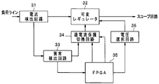
- the example of FIG. 2 shows an example of a specific configuration of the protection circuit PR1 (PR2) of FIG. 1 in which the protection processing units PRa and PRb are configured, and shows an example of a circuit that performs protection by detecting an overcurrent. ing.
- FIG. 2 shows an example in which the power generation units P1 to P3 in FIG. 1 are configured by a current detection circuit 31, a variable regulator 32, and a voltage selection circuit.
- the field programmable gate array (hereinafter referred to as FPGA) 35 in FIG. 2 can realize the function of the operation control unit 11 in FIG. Note that only the FPGA 35 in the configuration of FIG. 2 can use a common device for all power generation units and protection circuits.
- the FPGA 35 which is the operation control unit 11 is supplied with a power control parameter from the ID determination unit 14 (not shown), and a voltage selection circuit 36 receives a control signal for selecting a voltage to be generated by the variable regulator 32 based on the power control parameter. Output to.
- the voltage selection circuit 36 controls the variable regulator 32 to generate a power supply voltage according to an instruction from the FPGA 35.
- the load current detection result is input from the current detection circuit 31 to the variable regulator 32.
- the output current of the variable regulator 32 is controlled so that the load current from the current detection circuit 31 matches a predetermined target value specified by the FPGA 35.
- the variable regulator 32 generates power based on the instruction from the FPGA 35.
- the protection circuits PR1 and PR2 in FIG. 1 are configured by an abnormality detection circuit 33, an overcurrent protection switching circuit 34, and an FPGA 35.
- the abnormality detection circuit 33 receives the output of the current detection circuit 31, determines whether or not an abnormality has occurred in the load current, and outputs the determination result to the overcurrent protection switching circuit 34 and the FPGA 35.
- the FPGA 35 can output a shutdown instruction signal for shutting down the variable regulator 32 to the overcurrent protection switching circuit 34. Yes.
- the determination result of the abnormality detection circuit 33 and the shutdown instruction signal from the FPGA 35 can be input to the overcurrent protection switching circuit 34.
- the FPGA 35 when the determination result indicating the abnormality of the load current is input from the abnormality detection circuit 33, the FPGA 35 supplies the overcurrent protection switching circuit 34 to the overcurrent protection switching circuit 34 based on the power control parameter from the ID determination unit 14. A switching signal for selectively supplying one of the inputs to the control terminal of the variable regulator 32 is output.
- variable regulator 32 When the shutdown instruction signal is input to the control terminal by the overcurrent protection switching circuit 34, the variable regulator 32 is immediately shut down and stops operating.
- the variable regulator 32 stops output when a determination result indicating abnormality from the abnormality detection circuit 33 is input to the control end by the overcurrent protection switching circuit 34, and outputs when the determination result indicating abnormality is stopped. It is supposed to resume. That is, by switching the signal applied to the control terminal of the variable regulator 32, the functions of the protection processing units PRa and PRb are realized by the abnormality detection circuit 33, the overcurrent protection switching circuit 34, and the FPGA 35.
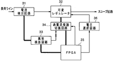
- FIGS. 3 and 4 are explanatory diagrams for explaining the control in the A and B protection modes, respectively.
- a signal flow is indicated by a thick line, and a signal is not transmitted by an x mark.
- the A protection mode is a protection mode designed to immediately shut down when an abnormality is detected
- the B protection mode is a protection mode designed not to shut down but to drop a voltage when an abnormality is detected. Will be described.
- the A protection mode is set for a power supply to a scope circuit that may cause heat generation at the distal end of the endoscope insertion portion, for example, an image sensor.
- a scope circuit that may cause heat generation at the distal end of the endoscope insertion portion, for example, an image sensor.
- the B protection mode is set for such a scope circuit.
- the reading unit 12 of the processor 10 reads the scope ID from the memory 24 and outputs it to the ID determination unit 14.
- the ID determination unit 14 reads the power control parameter corresponding to the scope ID from the data storage unit 13 and outputs it to the FPGA 35 (operation control unit 11).
- the FPGA 35 can grasp the type of power to be generated and the protection mode for each of the scope circuits 21 to 23 of the endoscope 20 based on the power control parameter.
- the scope circuit 21 is supplied with power in the A protection mode and the scope circuit 22 is supplied with power in the B protection mode.
- the variable regulators 32 of the power generation units P1 and P2 generate the power supply voltages selected by the voltage selection circuits 36, respectively.
- power is supplied to the scope circuits 21 and 22.
- the abnormality detection circuit 33 detects an abnormality from the output of the current detection circuit 31 of the power generation unit P1, and outputs a determination result indicating the abnormality to the FPGA 35 and the overcurrent protection switching circuit 34.
- the scope circuit 21 is supplied with power in the A protection mode, and the FPGA 35 generates a shutdown instruction signal according to a determination result indicating an abnormality from the abnormality detection circuit 33 and an overcurrent protection switching circuit 34. Causes the output of the FPGA 35 to be selected.
- a shutdown instruction signal from the FPGA 35 is supplied to the control terminal of the variable regulator 32 via the overcurrent protection switching circuit 34 when an overcurrent is detected.
- the variable regulator 32 stops the output.
- the shutdown is immediately performed and the power supply to the scope circuit 21 is stopped.
- the abnormality detection circuit 33 detects an abnormality based on the output of the current detection circuit 31 of the power generation unit P2, and outputs a determination result indicating the abnormality to the FPGA 35 and the overcurrent protection switching circuit 34.
- the scope circuit 22 is supplied with power in the B protection mode, and the FPGA 35 does not accept the determination result of the abnormality detection circuit 33 according to the determination result indicating the abnormality from the abnormality detection circuit 33, and shuts down the instruction signal. Does not occur. Further, the FPGA 35 causes the overcurrent protection switching circuit 34 to select the output of the abnormality detection circuit 33.
- the thick line in FIG. 4 shows such a signal flow, and a determination result indicating an abnormality from the abnormality detection circuit 33 due to detection of an overcurrent is supplied to the control terminal of the variable regulator 32 via the overcurrent protection switching circuit 34. Is done. Thereby, the variable regulator 32 stops the output. As a result, the load line current rapidly decreases. Then, the abnormality detection circuit 33 does not output a determination result indicating abnormality, and the variable regulator 32 resumes output.
- the scope circuit 22 is out of order, the load current becomes an abnormal value again by supplying power from the power generation unit P2. Then, the determination result indicating the abnormality from the abnormality detection circuit 33 is supplied to the variable regulator 32 again, and the output of the variable regulator 32 is stopped. Thereafter, the same operation is repeated, and the load current converges to a substantially constant value. Thus, constant current control is performed immediately after the occurrence of the overcurrent, thereby preventing the occurrence of the overcurrent.
- each power generation unit by providing a plurality of protection processing units in each power generation unit, it is possible to supply power in a plurality of protection modes, acquire a scope ID, and supply each power supply based on the scope ID. Allows you to select the protection mode. As a result, even when power is supplied to a plurality of types of endoscopes, it is possible to supply power corresponding to each scope circuit with a relatively small number of power generation units and protection circuits, thereby reducing the size of the apparatus. be able to.
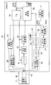
- FIG. 5 is a schematic view showing a second embodiment of the present invention. This embodiment shows another example of the protection mode. In FIG. 5, the same components as those of FIG.
- the processor 50 in FIG. 5 includes all the components of the processor 10 in FIG. 10, but the illustration of the power generation unit, the protection circuit, and the like other than the part related to the protection processing unit PRc3 that protects the C protection mode is omitted. To do. Note that the C protection mode will be described as a protection mode in which, for example, the drive power supply and drive circuit for the image sensor are stopped when an abnormality is detected.
- the endoscope 50 can be detachably attached to the processor 50.
- the endoscope 40 has an image sensor 41 disposed at the distal end of the insertion portion.
- the processor 50 includes an image sensor driving circuit 56 that supplies a drive signal to the image sensor 41, and a power generation unit P ⁇ b> 3 that supplies power to both the image sensor drive circuit 56 and the image sensor 41.
- a master clock is input to the processor 50, and a timing generator (hereinafter referred to as TG) 55 generates a timing signal for controlling each unit based on the master clock.
- the image sensor driving circuit 56 operates with power supplied from the power generation unit P3, and generates a drive signal for driving the image sensor 41 based on a timing signal from the TG 55.
- the imaging output from the imaging device 41 is supplied to the amplifier 51.
- the amplifier 51 amplifies the imaging output and outputs it to the CDS circuit 52.
- the CDS circuit 52 performs CDS (correlated double sampling) processing on the imaging output.
- the output of the CDS circuit 52 is given to an A / D converter 53.
- the A / D converter 53 converts the imaging output into a digital signal and outputs it to the signal processing unit 54.
- the signal processing unit 54 performs predetermined signal processing on the imaging output and generates a video signal based on the imaging output. By applying this video signal to a monitor (not shown), an endoscopic image is displayed on the display screen of the monitor.
- the imaging output from the imaging device 41 is transmitted to the processor 50 via a scope cable 42 inserted into the endoscope 40.
- a scope cable 42 inserted into the endoscope 40.
- the phase fluctuation of the imaging output is large.
- the PLL circuit 57 receives an imaging output and generates such a reference signal.
- the phase comparator 58 of the PLL circuit 57 obtains the phase difference between the imaging output and the output of the voltage controlled crystal oscillator (hereinafter referred to as VCXO) 60 and outputs it to the VCXO 60 via the LPF 59.
- the VCXO 60 outputs the reference signal while changing the oscillation frequency so that the phase difference from the phase comparator 58 becomes zero.
- a reference signal synchronized with the imaging output is generated by the PLL circuit 57 and provided to the signal processing unit 54.
- the signal processing unit 54 can perform signal processing using the reference signal synchronized with the imaging output.
- a protection processing unit PRc3 including a lock detection unit 61 and a time detection unit 62 is provided.
- the output of the LPF 59 becomes a predetermined constant voltage.
- the lock detection unit 61 can determine whether or not the PLL circuit 57 is in a locked state by receiving the output of the LPF 59. The determination result of the lock detection unit 61 is supplied to the time detection unit 62.
- the time detection unit 62 detects the time required for the PLL circuit 57 to establish a lock based on the output of the lock detection unit 61. When the PLL circuit 57 is not locked for a predetermined time or more, the time detection unit 62 determines that an abnormality has occurred in the system and generates a shutdown instruction signal. The shutdown instruction signal from the time detection unit 62 of the protection processing unit PRc3 is supplied to the power generation unit P3 via the switch PRS. The switch PRS is controlled by the operation control unit 11.
- the endoscope 40 is provided with a memory (not shown) that stores a scope ID, and the reading unit 12 (see FIG. 1) of the processor 50 reads the scope ID from the memory of the endoscope 40, so that the first ID is obtained.
- the operation control unit 11 is given a power control parameter corresponding to the endoscope 40. Based on the power control parameter input to the operation control unit 11 of the processor 50, the operation control unit 11 performs control so that power is supplied to the image sensor 41 in the C protection mode.
- the operation control unit 11 turns on the switch PRS when the protection mode is the C protection mode, and turns off the switch PRS when the protection mode is any other mode.
- the shutdown instruction signal is given from the protection processing unit PRc3
- the power generation unit P3 is immediately shut down and stops outputting.
- the reading unit 12 of the processor 50 reads the scope ID from the endoscope 40.
- Power control parameters based on the scope ID are supplied to the operation control unit 11.
- the operation control unit 11 can grasp the type of power to be generated and the protection mode for the image sensor 41 of the endoscope 40 based on the power control parameter.
- the power supply protection mode for the image sensor 41 is described as a C protection mode in which the power supply and the drive signal supply to the image sensor 41 are stopped when an abnormality is detected.
- the power generation unit P3 outputs the generated power to the image sensor 41 and the image sensor drive circuit 56.
- the image sensor drive circuit 56 generates a drive signal based on the timing signal from the TG 55 and supplies it to the image sensor 41.
- the image sensor 41 is supplied with electric power from the power generation unit P3 and is driven by a drive signal from the image sensor drive circuit 56 to perform imaging.
- the imaging output from the imaging device 41 is supplied to the processor 50 via the scope cable 42.
- the imaging output is amplified by the amplifier 51, subjected to CDS processing by the CDS circuit 52, converted into a digital signal by the A / D converter 53, and supplied to the signal processing unit.
- the imaging output from the imaging device 41 is supplied to the PLL circuit 57.
- the PLL circuit 57 generates a reference signal synchronized with the imaging output and outputs the reference signal to the signal processing unit 54.
- the signal processing unit 54 performs various kinds of signal processing on the imaging output using the reference signal from the PLL circuit 57, and generates and outputs a video signal.
- the lock detection unit 61 detects the lock state based on the output of the LPF 59, and outputs a detection result indicating that the lock state is not established to the time detection unit 62.
- the time detector 62 determines that an abnormality has occurred in the system and generates a shutdown instruction signal.
- the operation control unit 11 turns on the switch PRS to protect the power generation unit P3 in the C protection mode.
- the shutdown instruction signal from the time detection unit 62 is supplied to the power generation unit P3 via the switch PRS.
- the power generation part P3 stops the output.
- the same effect as that of the first embodiment can be obtained. That is, conventionally, it has been necessary to provide a power generation unit dedicated to the image sensor. However, the operation control unit selects and operates a different protection processing unit for each protection mode of the circuit to be controlled, thereby generating a common power source. It is possible to supply power in a protection mode corresponding to the image sensor using the unit. In the present embodiment, it is possible to simultaneously stop power supply to the two circuits of the image sensor and the image sensor drive circuit by detecting an abnormality, and it is possible to more reliably protect the image sensor and the like. .
- FIG. 6 is a flowchart showing the third embodiment of the present invention.
- the hardware configuration of this embodiment is the same as that of the first embodiment. This embodiment is different from the first embodiment only in the control of the operation control unit.
- the protection mode of each power generation unit is fixedly determined based on the scope ID.
- the protection mode of each power generation unit can be changed with the passage of a predetermined time or with the passage of a predetermined sequence.
- an inrush current may be generated when the operation of the power generation unit P is started.
- a control loop for controlling the variable regulator 32 from the current detection circuit 31 shown in FIG. 2 via the abnormality detection circuit 33 and the overcurrent protection switching circuit 34, that is, a constant current control loop is used. It is valid. Therefore, inrush current can be prevented by performing overcurrent protection in the B protection mode shown in FIG.
- the operation control unit 11 supplies power in the B protection mode until a predetermined time elapses after the operation starts even when power is supplied to a circuit that requires immediate shutdown.
- a predetermined time elapses it is possible to switch to power supply in the A protection mode.
- the operation control unit 11 may detect that a predetermined sequence has elapsed and change the protection mode. For example, when supplying power to the image sensor, the operation control unit 11 detects whether or not a video signal based on the imaging output is output, and supplies power in the B protection mode until the video signal is output. When the video signal is output, the power supply in the A protection mode may be switched thereafter.
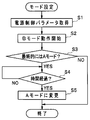
- FIG. 6 shows an example in which the protection mode is switched over time.
- the operation control unit 11 acquires a power control parameter corresponding to the scope ID in step S1 of FIG.
- the operation control unit 11 causes the protection circuit PR to select the protection processing unit PRb in the B protection mode, and instructs the power generation unit P to generate power.
- the power generation unit P generates power and supplies it to the target circuit.
- the operation control unit 11 determines whether or not the circuit to be controlled is finally subjected to overcurrent protection in the A protection mode based on the power supply control parameter (step S3).
- the operation control unit 11 determines whether or not a predetermined time has elapsed in step S4, and when the predetermined time has elapsed, in step S5
- the protection circuit PR selects the protection processing unit PRa in the A protection mode, and changes the overcurrent protection mode to the A protection mode.
- the protection mode can be changed according to the passage of time or the passage of a predetermined sequence.
- the inrush current prevention circuit can be omitted.
- FIG. 7 is a flowchart showing the fourth embodiment of the present invention.
- the hardware configuration of this embodiment is the same as that of the first embodiment. This embodiment is different from the first embodiment only in the control of the operation control unit.
- each power generation unit is driven according to a predetermined sequence, and each power generation unit is operated sequentially while determining whether each power generation unit is operating normally. Is.
- the operation control unit 11 acquires a power control parameter corresponding to the scope ID.
- the operation control unit 11 determines the order (power sequence) in which each power generation unit P1, P2,... Is activated and power supply is started based on the power control parameter (step S10).
- the operation control unit 11 starts a power generation operation from the first power generation unit P in the power sequence (step S11).
- step S12 the operation control unit 11 is in a standby state until power is generated from the power generation unit P that has started the power generation operation.
- the power control is managed only by the power sequence, not by time.
- the operation control unit 11 When power is generated from the power generation unit P that has started the power generation operation, the operation control unit 11 normally supplies power when the output is a predetermined threshold voltage, for example, (rated voltage ⁇ 0.8) or more. If the predetermined threshold voltage is not reached, it is determined that the power supply is not normally performed. For example, when the operation control unit 11 is configured by an FPGA, the operation control unit 11 converts the output of the power generation unit P into a digital signal and supplies the digital signal to the operation control unit 11. The output voltage can be detected.
- a predetermined threshold voltage for example, (rated voltage ⁇ 0.8) or more. If the predetermined threshold voltage is not reached, it is determined that the power supply is not normally performed.
- the operation control unit 11 is configured by an FPGA, the operation control unit 11 converts the output of the power generation unit P into a digital signal and supplies the digital signal to the operation control unit 11. The output voltage can be detected.
- the operation control unit 11 determines that the power supply is not normally performed, the operation control unit 11 shifts the processing from step S13 to step S17, stops the operation of the power generation unit P, and ends the processing. When it is determined that the power supply is normally performed, the operation control unit 11 shifts the processing from step S13 to step S14 and causes the power generation unit P to supply power to the target circuit.
- the operation control unit 11 determines whether or not the power generation operation of the last power generation unit P in the power sequence has ended in step S15. If not, the process returns to step S12 to return to the next power sequence. The power generation operation of the power generation unit P is started.
- step S15 the operation control unit 11 shifts the processing from step S15 to step S16, and finally all the operations are performed. It is determined whether or not the power supply is normally performed. For example, when the operation control unit 11 detects that the output of any one of the power generation units P is (rated voltage ⁇ 1.2) or more, it determines that the power supply is not normally performed. In step S17, all power supply is stopped.
- the order in which the power generation units are activated is controlled according to the power sequence corresponding to the endoscope connected to the processor 10.
- the operation control unit 11 starts the next power generation unit while confirming that each power supply has been normally generated according to the power supply sequence.
- a normal power supply voltage is supplied to each target circuit according to the power supply sequence, and normal operation can be expected in the endoscope.
Landscapes
- Health & Medical Sciences (AREA)
- Life Sciences & Earth Sciences (AREA)
- Surgery (AREA)
- Physics & Mathematics (AREA)
- Engineering & Computer Science (AREA)
- Optics & Photonics (AREA)
- Biomedical Technology (AREA)
- Veterinary Medicine (AREA)
- Biophysics (AREA)
- Pathology (AREA)
- Radiology & Medical Imaging (AREA)
- Nuclear Medicine, Radiotherapy & Molecular Imaging (AREA)
- Public Health (AREA)
- Heart & Thoracic Surgery (AREA)
- Medical Informatics (AREA)
- Molecular Biology (AREA)
- Animal Behavior & Ethology (AREA)
- General Health & Medical Sciences (AREA)
- Signal Processing (AREA)
- Astronomy & Astrophysics (AREA)
- General Physics & Mathematics (AREA)
- Multimedia (AREA)
- Endoscopes (AREA)
- Closed-Circuit Television Systems (AREA)
- Instruments For Viewing The Inside Of Hollow Bodies (AREA)
Abstract
Description
図1は本発明の第1の実施の形態に係る内視鏡装置を示すブロック図である。図1の内視鏡装置は、プロセッサ10及び内視鏡20によって構成されているが、プロセッサ10には内視鏡20だけでなく図示しない他の内視鏡も着脱自在に接続可能である。内視鏡20は、電源供給を受けて動作する電源供給の対象回路であるスコープ回路21~23を有している。なお、例えば、内視鏡20には図示しない撮像素子も構成されているが、電源供給の対象である撮像素子等もスコープ回路として表現するものとする。
図5は本発明の第2の実施の形態を示す概略図である。本実施の形態は保護モードの他の例を示すものである。図5において図1と同一の構成要素には同一符号を付して説明を省略する。
図6は本発明の第3の実施の形態を示すフローチャートである。本実施の形態のハードウェア構成は第1の実施の形態と同様である。本実施の形態は動作制御部の制御が第1の実施の形態と異なるのみである。
図7は本発明の第4の実施の形態を示すフローチャートである。本実施の形態のハードウェア構成は第1の実施の形態と同様である。本実施の形態は動作制御部の制御が第1の実施の形態と異なるのみである。
本出願は、2013年8月9日に日本国に出願された特願2013-166333号を優先権主張の基礎として出願するものであり、上記の開示内容は、本願明細書、請求の範囲、図面に引用されたものとする。
Claims (5)
- 内視鏡の1つ以上の対象回路に電源を夫々供給する1つ以上の電源生成部と、
前記内視鏡から該内視鏡に関するスコープ情報を取得するスコープ情報取得部と、
前記1つ以上の電源生成部に夫々対応して設けられ、1つ以上の保護モードで動作する1つ以上の保護回路と、
前記スコープ情報に対応した電源制御情報に基づいて、前記1つ以上の電源生成部を制御すると共に、前記各保護回路毎に1つの保護モードを選択する動作制御部と、
を具備したことを特徴とする内視鏡装置。 - 前記動作制御部は、前記電源制御情報に基づいて、前記各保護回路毎に選択する保護モードを、所定時間の経過又は所定シーケンスの経過によって変更可能である
ことを特徴とする請求項1に記載の内視鏡装置。 - 前記1つ以上の保護モードのうちの1つの保護モードは、異常発生時に、前記内視鏡に設けられた撮像素子に対する電源供給及び駆動信号の供給を同時に停止させるように設定される
ことを特徴とする請求項1又は2に記載の内視鏡装置。 - 前記保護回路は、
前記対象回路に流れる負荷電流を検出する電流検出回路と、
前記負荷電流の異常を検出する異常検出回路とを具備し、
前記異常検出回路の検出結果に基づいて前記1つ以上の保護モードのうちの1つの保護モードを選択して対応する前記電源生成部を制御する
ことを特徴とする請求項1乃至3のいずれか1つに記載の内視鏡装置。 - 前記保護回路は、
前記内視鏡に設けられた撮像素子からの撮像出力に同期した基準信号を生成するPLL回路のロック状態を検出するロック検知部と、
前記ロック検知部の検出結果に基づいて前記PLL回路がロック状態になるまでの時間を検出する時間検出部とを具備し、
前記時間検出部の検出結果に基づいて前記1つ以上の保護モードのうちの1つの保護モードを選択して対応する前記電源生成部を制御する
ことを特徴とする請求項1乃至3のいずれか1つに記載の内視鏡装置。
Priority Applications (4)
| Application Number | Priority Date | Filing Date | Title |
|---|---|---|---|
| CN201480013087.4A CN105188510B (zh) | 2013-08-09 | 2014-07-29 | 内窥镜装置 |
| JP2015505371A JP5767422B2 (ja) | 2013-08-09 | 2014-07-29 | 内視鏡装置 |
| EP14835139.8A EP2954834A4 (en) | 2013-08-09 | 2014-07-29 | ENDOSCOPIC APPARATUS |
| US14/849,081 US9610004B2 (en) | 2013-08-09 | 2015-09-09 | Endoscope apparatus with power generating section and protection circuit |
Applications Claiming Priority (2)
| Application Number | Priority Date | Filing Date | Title |
|---|---|---|---|
| JP2013-166333 | 2013-08-09 | ||
| JP2013166333 | 2013-08-09 |
Related Child Applications (1)
| Application Number | Title | Priority Date | Filing Date |
|---|---|---|---|
| US14/849,081 Continuation US9610004B2 (en) | 2013-08-09 | 2015-09-09 | Endoscope apparatus with power generating section and protection circuit |
Publications (1)
| Publication Number | Publication Date |
|---|---|
| WO2015019903A1 true WO2015019903A1 (ja) | 2015-02-12 |
Family
ID=52461241
Family Applications (1)
| Application Number | Title | Priority Date | Filing Date |
|---|---|---|---|
| PCT/JP2014/069947 Ceased WO2015019903A1 (ja) | 2013-08-09 | 2014-07-29 | 内視鏡装置 |
Country Status (5)
| Country | Link |
|---|---|
| US (1) | US9610004B2 (ja) |
| EP (1) | EP2954834A4 (ja) |
| JP (1) | JP5767422B2 (ja) |
| CN (1) | CN105188510B (ja) |
| WO (1) | WO2015019903A1 (ja) |
Cited By (4)
| Publication number | Priority date | Publication date | Assignee | Title |
|---|---|---|---|---|
| WO2016208685A1 (ja) * | 2015-06-26 | 2016-12-29 | オリンパス株式会社 | 内視鏡電源供給システム |
| JP6219004B1 (ja) * | 2016-05-24 | 2017-10-25 | オリンパス株式会社 | 内視鏡用カメラコントロールユニット |
| WO2018211852A1 (ja) * | 2017-05-18 | 2018-11-22 | オリンパス株式会社 | 内視鏡システム |
| JP2023546807A (ja) * | 2020-10-02 | 2023-11-08 | シラグ・ゲーエムベーハー・インターナショナル | 外科用システムにおける階層的動作モードを動作させるための方法 |
Families Citing this family (9)
| Publication number | Priority date | Publication date | Assignee | Title |
|---|---|---|---|---|
| JP6348854B2 (ja) * | 2015-02-03 | 2018-06-27 | 富士フイルム株式会社 | 内視鏡用プロセッサ装置、内視鏡システム及び内視鏡システムの非接触給電方法 |
| JP6353810B2 (ja) * | 2015-04-24 | 2018-07-04 | 富士フイルム株式会社 | 内視鏡システム |
| CN109310281B (zh) * | 2016-08-02 | 2021-03-12 | 奥林巴斯株式会社 | 内窥镜系统和信号处理装置 |
| CN109963492B (zh) * | 2016-11-17 | 2021-07-20 | 奥林巴斯株式会社 | 内窥镜装置、内窥镜装置的工作方法以及视频处理器 |
| JP6498856B1 (ja) * | 2017-07-07 | 2019-04-10 | オリンパス株式会社 | 自走式内視鏡装置及びその制御装置 |
| CN112804929B (zh) * | 2018-10-03 | 2024-02-06 | 奥林巴斯株式会社 | 内窥镜用电源装置 |
| US12226080B2 (en) * | 2019-10-21 | 2025-02-18 | Neoped Technology Co., Ltd. | Endoscope host and endoscope device for intelligently detecting organs |
| JP7818374B2 (ja) * | 2021-10-14 | 2026-02-20 | Hoya株式会社 | 内視鏡用プロセッサ、及び内視鏡システム |
| CN119112076B (zh) * | 2024-10-22 | 2025-06-24 | 深圳市视诺祺电子科技有限公司 | 一种基于智能镜种识别的内窥镜检测系统 |
Citations (5)
| Publication number | Priority date | Publication date | Assignee | Title |
|---|---|---|---|---|
| JPH07194530A (ja) * | 1993-12-28 | 1995-08-01 | Olympus Optical Co Ltd | 電子内視鏡装置 |
| JP2010088656A (ja) | 2008-10-08 | 2010-04-22 | Fujifilm Corp | 内視鏡用プロセッサ装置、内視鏡用プロセッサ装置の電源電圧供給方法、並びに内視鏡システム |
| JP2012011143A (ja) * | 2010-07-05 | 2012-01-19 | Olympus Corp | 内視鏡装置 |
| WO2012008259A1 (ja) * | 2010-07-12 | 2012-01-19 | オリンパスメディカルシステムズ株式会社 | 内視鏡画像処理装置及び内視鏡システム |
| WO2013042647A1 (ja) * | 2011-09-22 | 2013-03-28 | オリンパスメディカルシステムズ株式会社 | 内視鏡 |
Family Cites Families (11)
| Publication number | Priority date | Publication date | Assignee | Title |
|---|---|---|---|---|
| US5400267A (en) * | 1992-12-08 | 1995-03-21 | Hemostatix Corporation | Local in-device memory feature for electrically powered medical equipment |
| US5896166A (en) * | 1993-06-02 | 1999-04-20 | Envision Medical Corporation | Remote CCD video camera with non-volatile digital memory |
| US6638212B1 (en) * | 1999-07-27 | 2003-10-28 | Olympus Optical | Endoscope system having storage part of endoscope-related-data provided in endoscope |
| JP4610713B2 (ja) * | 2000-10-13 | 2011-01-12 | オリンパス株式会社 | 内視鏡装置 |
| JP4689206B2 (ja) * | 2004-07-26 | 2011-05-25 | オリンパス株式会社 | 電子内視鏡システム |
| JP4804062B2 (ja) * | 2005-07-29 | 2011-10-26 | オリンパス株式会社 | 内視鏡システム |
| JP4814717B2 (ja) * | 2006-07-28 | 2011-11-16 | Hoya株式会社 | 電子内視鏡、及び、電子内視鏡システム |
| JP4954659B2 (ja) * | 2006-10-10 | 2012-06-20 | 株式会社リコー | 撮像装置 |
| JP2009189529A (ja) * | 2008-02-14 | 2009-08-27 | Fujinon Corp | 内視鏡用プロセッサ装置 |
| JP6005989B2 (ja) * | 2012-05-16 | 2016-10-12 | オリンパス株式会社 | 内視鏡装置 |
| JP6258751B2 (ja) * | 2014-03-31 | 2018-01-10 | Hoya株式会社 | 負荷電圧制御装置、電子内視鏡および電子内視鏡システム |
-
2014
- 2014-07-29 CN CN201480013087.4A patent/CN105188510B/zh active Active
- 2014-07-29 JP JP2015505371A patent/JP5767422B2/ja not_active Expired - Fee Related
- 2014-07-29 WO PCT/JP2014/069947 patent/WO2015019903A1/ja not_active Ceased
- 2014-07-29 EP EP14835139.8A patent/EP2954834A4/en not_active Withdrawn
-
2015
- 2015-09-09 US US14/849,081 patent/US9610004B2/en not_active Expired - Fee Related
Patent Citations (5)
| Publication number | Priority date | Publication date | Assignee | Title |
|---|---|---|---|---|
| JPH07194530A (ja) * | 1993-12-28 | 1995-08-01 | Olympus Optical Co Ltd | 電子内視鏡装置 |
| JP2010088656A (ja) | 2008-10-08 | 2010-04-22 | Fujifilm Corp | 内視鏡用プロセッサ装置、内視鏡用プロセッサ装置の電源電圧供給方法、並びに内視鏡システム |
| JP2012011143A (ja) * | 2010-07-05 | 2012-01-19 | Olympus Corp | 内視鏡装置 |
| WO2012008259A1 (ja) * | 2010-07-12 | 2012-01-19 | オリンパスメディカルシステムズ株式会社 | 内視鏡画像処理装置及び内視鏡システム |
| WO2013042647A1 (ja) * | 2011-09-22 | 2013-03-28 | オリンパスメディカルシステムズ株式会社 | 内視鏡 |
Non-Patent Citations (1)
| Title |
|---|
| See also references of EP2954834A4 |
Cited By (9)
| Publication number | Priority date | Publication date | Assignee | Title |
|---|---|---|---|---|
| WO2016208685A1 (ja) * | 2015-06-26 | 2016-12-29 | オリンパス株式会社 | 内視鏡電源供給システム |
| JPWO2016208685A1 (ja) * | 2015-06-26 | 2017-06-29 | オリンパス株式会社 | 内視鏡システム |
| CN107405059A (zh) * | 2015-06-26 | 2017-11-28 | 奥林巴斯株式会社 | 内窥镜电源供给系统 |
| US10463230B2 (en) | 2015-06-26 | 2019-11-05 | Olympus Corporation | Endoscope system with power supply system |
| JP6219004B1 (ja) * | 2016-05-24 | 2017-10-25 | オリンパス株式会社 | 内視鏡用カメラコントロールユニット |
| WO2017203829A1 (ja) * | 2016-05-24 | 2017-11-30 | オリンパス株式会社 | 内視鏡用カメラコントロールユニット及び内視鏡システム |
| WO2018211852A1 (ja) * | 2017-05-18 | 2018-11-22 | オリンパス株式会社 | 内視鏡システム |
| JP2023546807A (ja) * | 2020-10-02 | 2023-11-08 | シラグ・ゲーエムベーハー・インターナショナル | 外科用システムにおける階層的動作モードを動作させるための方法 |
| JP7851922B2 (ja) | 2020-10-02 | 2026-04-27 | シラグ・ゲーエムベーハー・インターナショナル | 外科用システムにおける階層的動作モードを動作させるための方法 |
Also Published As
| Publication number | Publication date |
|---|---|
| EP2954834A4 (en) | 2016-11-30 |
| EP2954834A1 (en) | 2015-12-16 |
| US20150374204A1 (en) | 2015-12-31 |
| US9610004B2 (en) | 2017-04-04 |
| CN105188510A (zh) | 2015-12-23 |
| JPWO2015019903A1 (ja) | 2017-03-02 |
| JP5767422B2 (ja) | 2015-08-19 |
| CN105188510B (zh) | 2017-10-31 |
Similar Documents
| Publication | Publication Date | Title |
|---|---|---|
| JP5767422B2 (ja) | 内視鏡装置 | |
| JP6495565B1 (ja) | 医療表示装置 | |
| JP5037731B2 (ja) | 内視鏡画像処理装置及び内視鏡システム | |
| US7734160B2 (en) | Endoscope apparatus | |
| JP6219004B1 (ja) | 内視鏡用カメラコントロールユニット | |
| CN105705076A (zh) | 电子内窥镜系统、电子内窥镜、电源装置、电子内窥镜系统的动作方法 | |
| EP2062524A1 (en) | Endoscope device | |
| CN105377112A (zh) | 医疗显示装置以及内窥镜手术系统 | |
| CN105899124B (zh) | 内窥镜装置 | |
| JP2011200482A (ja) | リセット機能を備えた電源回路 | |
| JP6265815B2 (ja) | 電子内視鏡システム | |
| JP6564536B2 (ja) | 撮像装置 | |
| JP6165356B2 (ja) | 内視鏡システム | |
| JP2016214381A (ja) | 内視鏡装置 | |
| JP6523593B2 (ja) | 撮像装置 | |
| US20190102881A1 (en) | Endoscope apparatus and camera control unit | |
| JP6986858B2 (ja) | 内視鏡システム | |
| JP5361296B2 (ja) | 内視鏡装置 | |
| JP7266967B2 (ja) | 内視鏡ビデオプロセッサ、医療システム、及び制御方法 | |
| JP2006346357A (ja) | 内視鏡装置 | |
| JP2017205150A (ja) | 医療画像記録装置 | |
| JP2015181586A (ja) | 内視鏡装置、カメラヘッド、及び制御装置 | |
| JP6270497B2 (ja) | 電子内視鏡用プロセッサおよび電子内視鏡システム | |
| JP4839048B2 (ja) | 手術制御システム | |
| JP2015186359A (ja) | 電子機器 |
Legal Events
| Date | Code | Title | Description |
|---|---|---|---|
| WWE | Wipo information: entry into national phase |
Ref document number: 201480013087.4 Country of ref document: CN |
|
| ENP | Entry into the national phase |
Ref document number: 2015505371 Country of ref document: JP Kind code of ref document: A |
|
| 121 | Ep: the epo has been informed by wipo that ep was designated in this application |
Ref document number: 14835139 Country of ref document: EP Kind code of ref document: A1 |
|
| WWE | Wipo information: entry into national phase |
Ref document number: 2014835139 Country of ref document: EP |
|
| NENP | Non-entry into the national phase |
Ref country code: DE |