WO2015019972A1 - レドックスフロー電池 - Google Patents
レドックスフロー電池 Download PDFInfo
- Publication number
- WO2015019972A1 WO2015019972A1 PCT/JP2014/070422 JP2014070422W WO2015019972A1 WO 2015019972 A1 WO2015019972 A1 WO 2015019972A1 JP 2014070422 W JP2014070422 W JP 2014070422W WO 2015019972 A1 WO2015019972 A1 WO 2015019972A1
- Authority
- WO
- WIPO (PCT)
- Prior art keywords
- ion
- ions
- electrode electrolyte
- negative electrode
- positive electrode
- Prior art date
- Legal status (The legal status is an assumption and is not a legal conclusion. Google has not performed a legal analysis and makes no representation as to the accuracy of the status listed.)
- Ceased
Links
Images

Classifications
-
- H—ELECTRICITY
- H01—ELECTRIC ELEMENTS
- H01M—PROCESSES OR MEANS, e.g. BATTERIES, FOR THE DIRECT CONVERSION OF CHEMICAL ENERGY INTO ELECTRICAL ENERGY
- H01M8/00—Fuel cells; Manufacture thereof
- H01M8/18—Regenerative fuel cells, e.g. redox flow batteries or secondary fuel cells
- H01M8/184—Regeneration by electrochemical means
- H01M8/188—Regeneration by electrochemical means by recharging of redox couples containing fluids; Redox flow type batteries
-
- H—ELECTRICITY
- H01—ELECTRIC ELEMENTS
- H01M—PROCESSES OR MEANS, e.g. BATTERIES, FOR THE DIRECT CONVERSION OF CHEMICAL ENERGY INTO ELECTRICAL ENERGY
- H01M8/00—Fuel cells; Manufacture thereof
- H01M8/20—Indirect fuel cells, e.g. fuel cells with redox couple being irreversible
-
- H—ELECTRICITY
- H01—ELECTRIC ELEMENTS
- H01M—PROCESSES OR MEANS, e.g. BATTERIES, FOR THE DIRECT CONVERSION OF CHEMICAL ENERGY INTO ELECTRICAL ENERGY
- H01M2300/00—Electrolytes
- H01M2300/0002—Aqueous electrolytes
- H01M2300/0005—Acid electrolytes
- H01M2300/0011—Sulfuric acid-based
-
- Y—GENERAL TAGGING OF NEW TECHNOLOGICAL DEVELOPMENTS; GENERAL TAGGING OF CROSS-SECTIONAL TECHNOLOGIES SPANNING OVER SEVERAL SECTIONS OF THE IPC; TECHNICAL SUBJECTS COVERED BY FORMER USPC CROSS-REFERENCE ART COLLECTIONS [XRACs] AND DIGESTS
- Y02—TECHNOLOGIES OR APPLICATIONS FOR MITIGATION OR ADAPTATION AGAINST CLIMATE CHANGE
- Y02E—REDUCTION OF GREENHOUSE GAS [GHG] EMISSIONS, RELATED TO ENERGY GENERATION, TRANSMISSION OR DISTRIBUTION
- Y02E60/00—Enabling technologies; Technologies with a potential or indirect contribution to GHG emissions mitigation
- Y02E60/30—Hydrogen technology
- Y02E60/50—Fuel cells
Definitions
- the present invention relates to a redox flow battery.
- the present invention relates to a redox flow battery that can suppress generation of precipitates in a positive electrode.
- a redox flow battery is a secondary battery that performs charging and discharging by supplying a positive electrode electrolyte and a negative electrode electrolyte to a battery cell in which a diaphragm is interposed between a positive electrode and a negative electrode.
- the redox flow battery electrolyte used in such a redox flow battery normally uses metal ions whose valence changes as a result of oxidation and reduction as an active material.
- an iron (Fe 2+ / Fe 3+ ) -chromium (Cr 3+ / Cr 2+ ) -based redox flow battery using iron (Fe) ions as a positive electrode active material and chromium (Cr) ions as a negative electrode active material For example, an iron (Fe 2+ / Fe 3+ ) -chromium (Cr 3+ / Cr 2+ ) -based redox flow battery using iron (Fe) ions as a positive electrode active material and chromium (Cr) ions as a negative electrode active material,
- a vanadium (V 2+ / V 3+ -V 4+ / V 5+ ) -based redox flow battery using V ions as an active material can be given.
- RF batteries With the future expansion of the use of RF batteries, the development of RF batteries with higher energy density is desired. In particular, it is desired to develop a new RF battery capable of stably supplying metal ions used for the active material, and preferably stably supplying at low cost.
- manganese-based redox flow battery using manganese (Mn) ions as a positive electrode active material.
- Mn manganese
- generation of precipitates in the positive electrode may occur.
- a typical example of this precipitate is an oxide of Mn ions. Therefore, the density
- Patent Document 1 proposes a manganese-based redox flow battery in which titanium (Ti) ions are contained in a positive electrode electrolyte. Thereby, the deposit which generate
- the generation of precipitates can be suppressed by setting the operating condition of this redox flow battery to 90% or less of the state of charge (SOC) of the positive electrode electrolyte.
- SOC state of charge
- the generation of precipitates in the positive electrode may occur. In particular, when the RF battery is placed in a standby state with a high charge state, the generation of precipitates with time may occur.
- one of the objects of the present invention is to provide a redox flow battery capable of suppressing the generation of precipitates in the positive electrode.
- a redox flow battery performs charge and discharge by supplying a positive electrode electrolyte and a negative electrode electrolyte to a battery cell including a positive electrode, a negative electrode, and a diaphragm interposed between the two electrodes.
- the positive electrode electrolyte contains manganese ions and added metal ions
- the negative electrode electrolyte is at least one metal ion selected from titanium ions, vanadium ions, chromium ions, and zinc ions.
- the additive metal ion contained in the positive electrode electrolyte is at least one of aluminum ion, cadmium ion, indium ion, tin ion, antimony ion, iridium ion, gold ion, lead ion, bismuth ion and magnesium ion.
- the redox flow battery of the present invention can suppress the generation of precipitates on the positive electrode.
- the redox flow battery according to the embodiment performs charge and discharge by supplying a positive electrode electrolyte and a negative electrode electrolyte to a battery cell including a positive electrode, a negative electrode, and a diaphragm interposed between the two electrodes.
- the positive electrode electrolyte contains manganese (Mn) ions and added metal ions
- the negative electrode electrolyte is composed of titanium (Ti) ions, vanadium (V) ions, chromium (Cr) ions, and zinc (Zn) ions. Contains at least one selected metal ion.
- the additive metal ions contained in the positive electrode electrolyte are aluminum (Al) ions, cadmium (Cd) ions, indium (In) ions, tin (Sn) ions, antimony (Sb) ions, iridium (Ir) ions, gold It is at least one of (Au) ion, lead (Pb) ion, bismuth (Bi) ion, and magnesium (Mg) ion.
- the additive metal ion means a substance that has a function of mainly suppressing the generation of precipitates in the positive electrode electrolyte and does not actively function as an active material.
- the negative electrode electrolyte further contains additional metal ions, and the additional metal ions contained in the negative electrode electrolyte are Al ions, Cd ions, In ions, Sn ions, Sb ions, The form which is at least 1 type of Ir ion, Au ion, Pb ion, Bi ion, and Mg ion is mentioned.
- the negative electrode electrolyte contains at least one of the added metal ions, (1) the battery reactivity of the metal ions functioning as the negative electrode active material can be increased (the reaction rate can be increased), (2) depending on the ion species Expected to be effective as an active material and (3) to suppress generation of hydrogen accompanying water decomposition.
- the positive electrode electrolyte contains Ti ions, the generation of precipitates can be further suppressed.
- the RF battery of the embodiment includes a form in which the concentration of Ti ions contained in the positive electrode electrolyte is 5 M or less.
- M shown as a unit of concentration means volume molar concentration, that is, mol / L (mol / liter).
- concentration the concentration of Ti ions contained in the cathode electrolyte
- the concentration of Mn ions contained in the negative electrode electrolyte is within the above range, the relative concentration of Ti ions contained in the negative electrode electrolyte does not decrease too much, and an RF battery having a high energy density can be obtained.
- the concentration of Mn ions functioning as an active material in the positive electrode and the concentration of metal ions functioning as an active material in the negative electrode is within the above range, (1) sufficient metal element to perform the valence change reaction (2) Even when the electrolytic solution is an aqueous acid solution, it can be dissolved well, and the productivity of the electrolytic solution is excellent.
- the total concentration is used.
- the negative electrode electrolyte contains titanium ions, and at least one of the concentration of Mn ions contained in the positive electrode electrolyte and the concentration of Ti ions contained in the negative electrode electrolyte is 0.3M or more and 5M.
- concentration of Mn ions contained in the positive electrode electrolyte and the concentration of Ti ions contained in the negative electrode electrolyte is 0.3M or more and 5M.
- the RF battery of the embodiment includes a form in which the total concentration of the added metal ions in the positive electrode electrolyte is 0.001 M or more and 1 M or less.
- the additive metal ion contained in at least one of the positive electrode electrolyte and the negative electrode electrolyte or the additive metal ion contained in the negative electrode electrolyte is at least one of the following (1) to (10): The form which satisfy
- Al ions are monovalent Al ions, divalent Al ions, and at least one of trivalent Al ions
- Cd ions are at least one of monovalent Cd ions and divalent Cd ions (3 )
- In ion is a monovalent In ion, a divalent In ion, and at least one of a trivalent In ion
- Sn ion is a divalent Sn ion, and at least one of a tetravalent Sn ion (5)
- Sb At least one of trivalent Sb ion and pentavalent Sb ion (6)
- Ir ion is monovalent Ir ion, bivalent Ir ion, trivalent Ir ion, tetravalent Ir ion, pentavalent Ir ion
- Au ions are monovalent Au ions, divalent Au ions, trivalent Au ions, t
- At least one (8) Pb ion is divalent Pb ion and at least one of tetravalent Pb ion (9) Bi ion is trivalent Bi ion and at least one of pentavalent Bi ion (10) Mg ion Is at least one of monovalent Mg ions and divalent Mg ions
- Mn ions are at least one of divalent Mn ions and trivalent Mn ions
- at least one of the positive electrode electrolyte and the negative electrode electrolyte contains Ti ions
- the standard oxidation-reduction potential can be increased and a high electromotive force RF battery can be obtained.
- the positive electrode electrolyte contains Ti ions having any one of the valences described above, the generation of precipitates can be suppressed, and the configurations of the electrolyte solutions of both electrodes can be made common. Therefore, it is excellent in productivity of the electrolytic solution.
- the negative electrode electrolyte may contain Ti ions as an active material.
- Ti ions take the above valence
- the contained Ti ions can be efficiently used for the battery reaction, and an RF battery with high energy density can be obtained.
- the negative electrode electrolyte contains Mn ions having any one of the above valences, the electrolytes of both electrodes can have a common configuration, and the productivity of the electrolyte is excellent.
- the RF battery 1 of the present embodiment is a one-component Ti / Mn system in which the positive electrode active material is Mn ions and the negative electrode active material is Ti ions, and the positive electrode electrolyte and the negative electrode electrolyte use an electrolyte solution having the same configuration.
- RF battery In FIG. 1, solid arrows indicate charging, and broken arrows indicate discharge, and metal ions shown in the tanks 106 and 107 for both electrolytes are Mn ions that are positive electrode active materials and Ti ions that are negative electrode active materials. Only shown. It should be noted that the valences of Mn ions and Ti ions show only typical forms, and valences other than those shown can also be taken. In addition, an active material other than the both element ions may be included.
- the RF battery 1 typically includes a power generation unit 300 (for example, a solar power generation device, a wind power generation device, and other general power plants) via an AC / DC converter 200 and a transformer facility 210. And a load (here, power system / customer 400). Then, the power generated by the power generation unit 300 is charged and stored, or the stored power is discharged and supplied to the power system / customer 400.
- the RF battery 1 includes a battery cell 100 and a circulation mechanism (tank, conduit, pump) for supplying an electrolytic solution to the battery cell 100 as in the case of a conventional RF battery.
- the battery cell 100 in the RF battery 1 includes a positive electrode cell 102 incorporating a positive electrode 104, a negative electrode cell 103 incorporating a negative electrode 105, and a diaphragm 101 that separates both the cells 102 and 103 and transmits ions.
- a positive electrode electrolyte tank 106 for storing a positive electrode electrolyte is connected to the positive electrode cell 102 via conduits 108 and 110.
- a negative electrode electrolyte tank 107 that stores a negative electrode electrolyte is connected to the negative electrode cell 103 via conduits 109 and 111.
- the conduits 108 and 109 are provided with pumps 112 and 113 for circulating the electrolytes of both electrodes, respectively.
- the battery cell 100 is connected to the positive electrode cell 102 (positive electrode 104) and the negative electrode cell 103 (negative electrode 105) by the conduits 108 to 111 and the pumps 112 and 113, respectively.
- metal ions in this embodiment, Mn ions in the positive electrode and Ti ions in the negative electrode
- Mn ions in the positive electrode and Ti ions in the negative electrode that become the active material in the electrolyte solution in both electrodes by circulating and supplying the negative electrode electrolyte in the tank 107 To charge and discharge.
- the battery cell 100 is normally used in a form called a cell stack in which a plurality of single cells each having a positive electrode 104 (positive cell 102), a negative electrode 105 (negative electrode 103), and a diaphragm 101 are stacked.
- the cell stack has a bipolar plate (not shown) in which the positive electrode 104 is disposed on one surface and the negative electrode 105 is disposed on the other surface, a liquid supply hole for supplying an electrolytic solution, and a drain hole for discharging the electrolytic solution.
- a cell frame provided with a frame (not shown) formed on the outer periphery of the bipolar plate is used.
- the liquid supply hole and the drainage hole constitute an electrolyte flow path, and the flow path is connected to the conduits 108 to 111.
- the cell stack is configured by stacking a cell frame, a positive electrode 104, a diaphragm 101, a negative electrode 105, a cell frame,.
- a known configuration can be used as appropriate.
- Electrode electrolyte Different electrolytes may be used for the positive electrode electrolyte and the negative electrode electrolyte, respectively, but both electrolytes are common to the positive electrode electrolyte and the negative electrode electrolyte used in the RF battery 1 of the present embodiment. It is configured.
- This electrolytic solution contains a plurality of metal ions. More specifically, the sulfuric acid aqueous solution contains Mn ions that become active material ions in the positive electrode, Ti ions that become active material ions in the negative electrode, and additive metal ions.
- this electrolytic solution will be described in detail.
- the active material ion is a metal ion contained in the electrolytic solution, and participates in the battery reaction by a change in valence due to the transfer of electrons.
- active material ions in both electrodes will be described, and Ti ions in the positive electrode electrolyte and Mn ions in the negative electrode electrolyte will be described together.
- Mn ions contained in the positive electrode electrolyte serve as active material ions, and Ti ions do not actively function as active materials.
- This Mn ion can have at least one valence of bivalent, trivalent, and tetravalent in the electrolytic solution. Specifically, during discharge: divalent Mn ions (Mn 2+ ) are present, during charge: trivalent Mn ions (Mn 3+ ) are present, and both Mn ions are present by repeated charge and discharge. It becomes. Therefore, when the positive electrode electrolyte contains the above two Mn ions, the standard oxidation-reduction potential can be increased and a high electromotive force RF battery can be obtained.
- Tetravalent Mn is considered to be a precipitate (MnO 2 ), but this MnO 2 is not a solid precipitate, but is considered to exist in a stable state that seems to be dissolved in the electrolyte.
- MnO 2 is reduced (discharged) to Mn 2+ as a two-electron reaction during discharge, that is, MnO 2 acts as an active material and can be used repeatedly, thereby contributing to an increase in battery capacity.
- MnO 2 acts as an active material and can be used repeatedly, thereby contributing to an increase in battery capacity.
- the presence of a slight amount (about 10% or less of the total amount (mol) of Mn ions) of tetravalent Mn is allowed.
- the positive electrode electrolyte may contain Ti ions. This is because the generation of precipitates can be further suppressed.
- the concentration of the Ti ions is preferably 5M or less.
- concentration of Ti ion in positive electrode electrolyte solution can be 0.3M or more, 0.5M or more, and also 1M or more.
- the concentration of Ti ions in the positive electrode electrolyte is easily 5M or less, and more preferably 2M or less. This is because the effect of suppressing precipitates is easily exhibited, but the relative concentration of Mn ions contained in the positive electrode electrolyte does not decrease too much, and an RF battery having a high energy density can be obtained.
- the concentration of Ti ions contained in the positive electrode electrolyte is set to be the same as the concentration of Ti ions contained in the negative electrode electrolyte.
- the configuration of the electrolyte solution of both electrodes can be made a common configuration, and the productivity of the electrolyte solution is excellent.
- Ti ions contained in the negative electrode electrolyte serve as active material ions, and Mn ions do not actively function as active materials.
- tetravalent Ti ions Ti 4+ , TiO 2+, etc.
- trivalent Ti ions Ti 3+
- V ions not only the Ti ions but also at least one of V ions, Cr ions, and Zn ions may be used.
- V ions they contain at least one of divalent V ions and trivalent V ions.
- Cr ions they contain at least one of divalent Cr ions and trivalent Cr ions.
- Zn ions divalent Zn ions are contained.
- V 3+ trivalent V ions
- V 2+ divalent V ions
- Cr 3+ trivalent Cr ions
- divalent Cr ions Cr 2+
- Zn metal zinc
- each of the metal ions to be used as the active material ions for the negative electrode may be used singly or in combination of two or more thereof.
- the standard redox potential of each metal ion is taken into consideration so that each active material ion sequentially performs a battery reaction as the voltage increases during charging. It is preferable to combine them. For example, it is preferable that Ti 3+ / Ti 4+ , V 2+ / V 3+ , and Cr 2+ / Cr 3+ are combined in order of potential.
- the negative electrode electrolyte may contain Mn ions.
- the concentration of the Mn ions is preferably 0.3M or more and 5M or less. This is because, as in the case of the positive electrode electrolyte, the relative concentration of Ti ions contained in the negative electrode electrolyte does not decrease too much, and an RF battery having a high energy density can be obtained.
- the concentration of Mn ions contained in the negative electrode electrolyte is the same as that of Mn ions contained in the positive electrode electrolyte, the configuration of the electrolytes of both electrodes can be made common, and the productivity of the electrolyte can be improved. Excellent.
- concentration of the active material ion contained in the electrolyte solution of both electrodes all are 0.3M or more and 5M or less. This is because if the concentration of the active material ions is less than 0.3 M, it is difficult to ensure a sufficient energy density (for example, about 10 kWh / m 3 ) as a large-capacity storage battery. Accordingly, the concentration of the active material ions is preferably higher, and is preferably 0.5M or more, and more preferably 1.0M or more.
- the electrolyte solvent is an aqueous acid solution as in the present embodiment, the solubility of the active material ions may be reduced due to an increase in the acid concentration. Therefore, the upper limit of the total concentration of active material ions at one electrode is preferably 5M or less.
- the proportion of Ti ions in the metal ions included in the negative electrode electrolyte is larger. It is because it can be set as the RF battery from which a high electromotive force is obtained. At this time, for the same reason as described above, it is preferable that at least one of the concentration of Mn ions functioning as an active material in the positive electrode and the concentration of Ti ions functioning as an active material in the negative electrode be 0.3 M or more and 5 M or less.
- the additive metal ion means a substance that has a function of mainly suppressing the generation of precipitates in the positive electrode electrolyte and does not actively function as an active material.
- the added metal ion when the added metal ion is contained in the negative electrode electrolyte, (1) the battery reactivity of the metal ion functioning as the negative electrode active material can be increased (the reaction rate can be increased), (2) depending on the ion species It may function as an active material (3) At least one of the effects that generation of hydrogen accompanying water decomposition can be suppressed is expected.
- additive metal ions include at least one of Al ions, Cd ions, In ions, Sn ions, Sb ions, Ir ions, Au ions, Pb ions, Bi ions, and Mg ions. These metal ions may exist as metal ions having the following valence in the electrolytic solution, for example.
- Al ion at least one of monovalent Al ion, divalent Al ion, and trivalent Al ion
- Cd ion at least one of monovalent Cd ion and divalent Cd ion (3 )
- In ion at least one of monovalent In ion, divalent In ion, and trivalent In ion
- Sn ion at least one of divalent Sn ion and tetravalent Sn ion
- Sb Ion at least one of trivalent Sb ion and pentavalent Sb ion
- Ir ion monovalent Ir ion, divalent Ir ion, trivalent Ir ion, tetravalent Ir ion, pentavalent Ir ion Ir ion and at least one kind of hexavalent Ir ion
- Au ion monovalent Au ion, divalent Au ion, trivalent Au ion, tetravalent Au
- the positive electrode electrolyte contains at least one of the added metal ions, thereby suppressing the generation of precipitates. Moreover, it is anticipated that said effect will be show
- this concentration is preferably 0.005M or more, more preferably 0.01M or more, and further preferably 0.1M or more.
- the total concentration of the added metal ions at each electrode exceeds 1M, the ratio of the active material ions in the electrolytic solution decreases, and the energy density decreases.
- the total concentration of the added metal ions at each electrode is preferably 1M or less, more preferably 0.8M or less, and 0.5M or less. Further preferred.
- a compound (typically an oxide or a sulfuric acid compound) containing the added metal ions may be dissolved in the electrolytic solution.
- the added metal ion may function as an active material.
- Pb ions contained in the positive electrode and Sn ions contained in the negative electrode electrolyte can function as active materials.
- Zn ions contained in the negative electrode electrolyte mainly function as an active material, but are expected to function as additive metal ions.
- the type and concentration of metal ions contained in the positive electrode electrolyte are the same as the type and concentration of metal ions contained in the negative electrode electrolyte.
- the metal ions at each electrode move to the counter electrode with the liquid transfer, so that the metal ions that originally react as active materials at each electrode are reduced, the battery capacity is reduced, and the energy density is reduced. It is possible to suppress the phenomenon of lowering, (2) easy to correct even if the liquid volume becomes unbalanced by liquid transfer, and (3) excellent electrolyte solution manufacturability. From this point of view, in this embodiment, the configuration of the bipolar electrolyte is common. Therefore, when the negative electrode electrolyte contains active material ions other than Ti ions, the positive electrode electrolyte may contain the above-described negative electrode active material ions.
- water-soluble ions can be suitably used as the metal ions contained in the electrolytic solution.
- an aqueous solution can be suitably used as a solvent for the positive electrode electrolyte and the negative electrode electrolyte.
- the solvent is an aqueous solution of an acid containing sulfuric acid or sulfate, (1) improvement in stability of various metal ions, improvement in reactivity of active material ions, and improvement in solubility may be obtained.
- the acid concentration in the electrolyte solution of each electrode is preferably less than 5M, and particularly 4.5M or less, and more preferably 1M or more and 4M or less.
- the solvent an aqueous solution containing a known acid or a known salt in addition to sulfuric acid or a sulfate can be used.
- Electrode Examples of the material of the positive electrode 104 and the negative electrode 105 include a nonwoven fabric (carbon felt) made of carbon fiber.
- a nonwoven fabric carbon felt
- oxygen gas is hardly generated even when the oxygen generation potential is reached during charging, (2) the surface area is large, (3) the electrolyte It has the effect of being excellent in the distribution of
- other known electrodes can be used.
- diaphragm 101 examples include an ion exchange membrane such as a cation exchange membrane or an anion exchange membrane.
- the ion exchange membrane has the effects of (1) excellent separation between the metal ions of the positive electrode active material and the metal ions of the negative electrode active material, and (2) excellent permeability of H + ions (charge carriers inside the battery). Yes, it can be suitably used for the diaphragm 101.
- a known diaphragm can be used.
- the positive electrode electrolyte tank 106, the negative electrode electrolyte tank 107, and the conduits 108 to 111 are members in contact with the RF electrolyte.
- the constituent material of the member (106-111), density (ASTM D 1505) is 0.080 g / cm 3 or more, there is a 0.960 g / cm 3 within the range, the melt flow rate (ASTM D 1238, measuring conditions : 190 ° C., load 2.16 kg) in the range of 0.01 g / 10 min or more and 20 g / 10 min or less, or an ethylene homopolymer having a density and a melt flow rate in the above range. Examples include coalescence.
- the RF battery of the embodiment described above can suppress the generation of precipitates on the positive electrode even when the state of charge is high. As a result, since the energy density is increased, it is not necessary to use a large amount of the electrolytic solution, and the size of equipment such as a tank for the electrolytic solution can be reduced and the space for installing these equipment can be reduced.
- Test Example 1 [Observation of changes over time] In Test Example 1, it was observed whether precipitates were generated in the positive electrode electrolyte, assuming an RF battery to be used in actual operation.
- an RF battery having the same configuration as that of the above-described embodiment was prototyped. In this RF battery, carbon felt having an electrode area of 9 cm 2 was used for both electrodes, and a cation exchange membrane was used for the diaphragm (the same applies to each test example described later unless otherwise specified).
- An electrolyte solution (sample) having the same (common) composition was used for each of the positive electrode electrolyte and the negative electrode electrolyte.
- Sample 1 an aqueous solution was prepared using manganese sulfate, titanium sulfate, and sulfuric acid.
- This sample 1 has a manganese ion concentration of 1.0M, a titanium ion concentration of 1.0M, and a sulfate ion concentration (total concentration) of 5.0M.
- Sample 2 and Sample 3 were prepared using Sample 1 and bismuth (III) sulfate.
- Sample 2 has a bismuth ion concentration of 0.1M and a sulfate ion concentration (total concentration) of 5.15M.
- Sample 3 has a bismuth ion concentration of 0.02M and a sulfate ion concentration (total concentration) of 5.03M. .
- production of the precipitation with time was observed when the sample 1 to the sample 3 were each made into electrolyte solution.
- the RF battery using each sample was observed even when the charged state of the positive electrode (positive electrode SOC) was 90%, and the RF battery using Sample 1 as the electrolyte was 70% charged.
- the RF battery was charged by charging the RF battery using each sample at a charging current of 315 mA and a charging end voltage of 2V.
- the state of charge was determined as follows.
- each RF battery charged to a specified charge state was allowed to stand at room temperature (25 ° C.) to be in a standby state, and whether or not precipitates were generated was visually observed over time. Precipitates are observed as precipitates in the positive electrode electrolyte. The observation results are shown in Table 1.
- Test Example 2 [Electrochemical measurement]
- an oxidation-reduction reaction current and oxidation-reduction reaction at each electrode using an RF battery using a carbon felt electrode of 0.785 cm 2 with the same configuration as in Test Example 1 above, and Sample 1 and Sample 2 were used.
- the potential was measured.
- the redox reaction current and the redox reaction potential were measured by potentiostat / galvanostat (Hokuto Denko Co., Ltd., HZ-5000) by tripolar cyclic voltammetry with the reference electrode being Ag / AgCl. went.
- the electrode to be measured was a working electrode
- the counter electrode was a counter electrode
- a reference electrode was placed in the electrolyte solution on the electrode side to be measured.
- the electrolyte solution of the working electrode was measured in a stationary state and the counter electrode in a circulating state.
- the sweep speed was 3 mV / s.
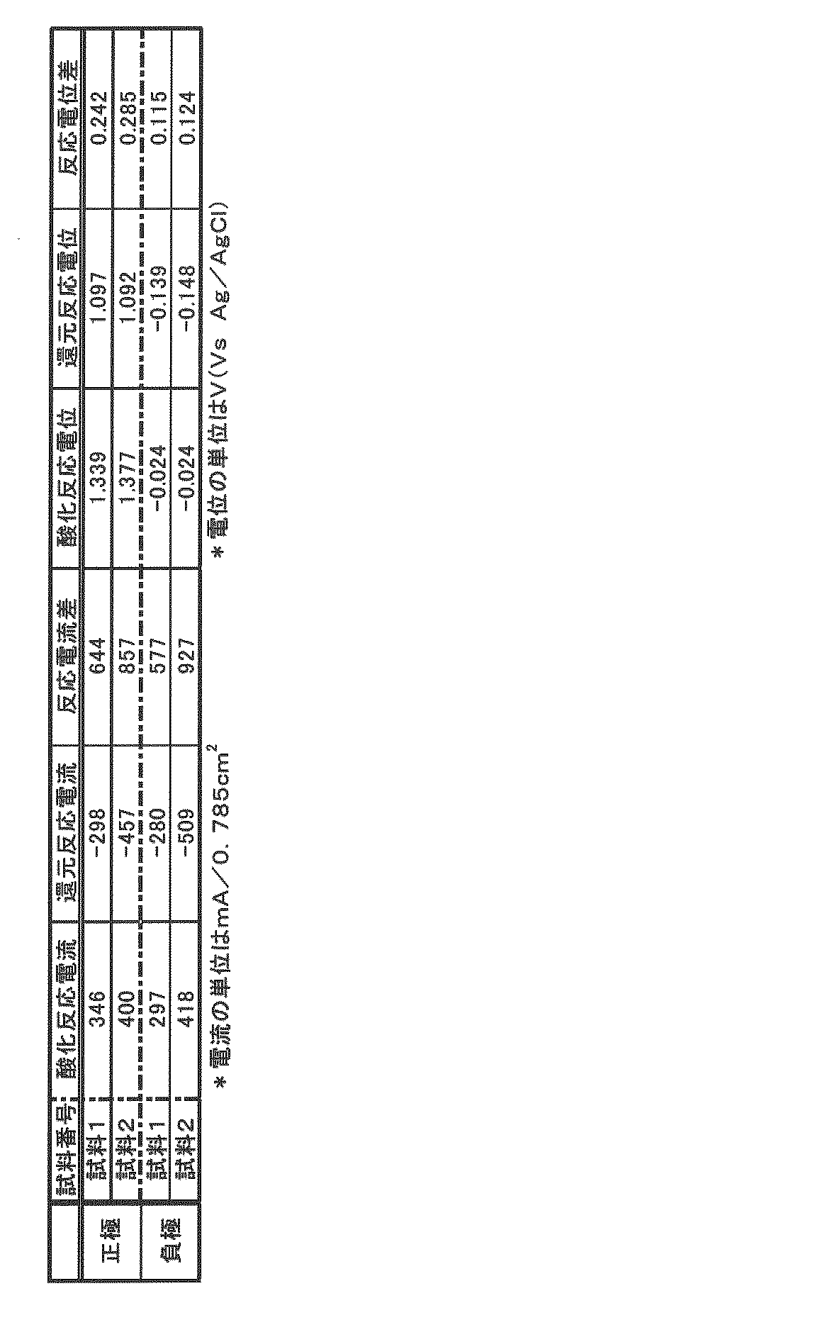
- Table 2 the unit of the item related to current is mA / 0.785 cm 2
- the unit of the item related to potential is V (Vs Ag / AgCl).
- the reaction current difference between the two electrodes when the sample 2 is used is larger than the reaction current difference between the two electrodes when the sample 1 is used.
- the sample 2 is about 1.3 times larger for the positive electrode and about 1.6 times larger for the negative electrode than the sample 1 is used.
- the reaction potential difference is not significantly different between the case where the sample 2 is used and the case where the sample 1 is used. As mentioned above, it turns out that an energy density improves because electrolyte solution contains an addition metal ion.
- Test Example 3 [Examination of charging status]
- the state of charge of the positive electrode of the RF battery using Sample 1 and Sample 2 as the electrolyte was determined. However, it differs from Test Example 1 in that the positive electrode electrolyte solution was 10 ml, the negative electrode electrolyte solution was 25 ml, and the electrode area was 9 cm 2 . The state of charge was adjusted based on the calculation method for each item described in Test Example 1 above. The results are shown in Table 3.
- Test Example 4 a charge / discharge cycle test was performed using an RF battery using Sample 2 as an electrolyte.
- the RF battery has the same configuration as in Test Example 1 except that the positive electrode electrolyte is 6 ml, the negative electrode electrolyte is 9 ml, and the charging current and discharging current are 450 mA.
- the charging side switching voltage (voltage for switching from charging to discharging) was 1.5 V, the discharging side switching voltage (voltage for switching from discharging to charging) was 1.0 V, and the number of cycles was 3.
- Test Example 5 [Observation of changes over time] In Test Example 5, it was observed whether deposits were generated in the positive electrode electrolyte assuming an RF battery to be used in actual operation.
- an RF battery having the same configuration as that of the above-described embodiment was prototyped.
- As the positive electrode electrolyte an Al-added sample, an Mg-added sample, an Sn-added sample, and a metal-free sample were prepared as follows. Manganese sulfate, titanium sulfate, sulfuric acid, and aluminum sulfate are used as Al-added samples.
- Manganese ion (divalent) concentration is 1.0M
- titanium ion (tetravalent) concentration is 1.0M
- sulfate ion concentration total concentration
- An electrolyte solution in this case, an aqueous solution having a composition of 5.0M and an Al ion (trivalent) concentration of 0.1M was prepared.
- Manganese sulfate, titanium sulfate, sulfuric acid, and magnesium sulfate are used as Mg-added samples.
- Manganese ion (divalent) concentration is 1.0M
- titanium ion (tetravalent) concentration is 1.0M
- sulfate ion concentration (total concentration) was prepared with an electrolyte solution (in this case, an aqueous solution) having a composition of 5.0M and Mg ion (divalent) concentration of 0.1M.
- an electrolyte solution in this case, an aqueous solution
- Mg ion (divalent) concentration as the Sn-added sample.
- Manganese ion (divalent) concentration is 1.0M
- titanium ion (tetravalent) concentration is 1.0M
- sulfate ion concentration (total concentration) Prepared an electrolyte solution (here, an aqueous solution) having a composition of 5.0M and Sn ion (divalent) concentration of 0.05M.
- Manganese sulfate, titanium sulfate, and sulfuric acid were used as the metal-free samples, and the manganese ion (divalent) concentration was 1.0M, the titanium ion (tetravalent) concentration was 1.0M, and the sulfate ion concentration (total concentration) was 5.
- An electrolyte solution in this case, an aqueous solution having a composition of 0.0 M was prepared.
- the negative electrode electrolyte was prepared in the same manner as the positive electrode electrolyte.
- a 9 cm 2 carbon felt was used for each electrode of the small cell, and a cation exchange membrane was used for the diaphragm.
- the one-electron reaction of manganese ions is Mn 2+ ⁇ Mn 3+ + e ⁇ .
- Charged electricity (A ⁇ h) Charging current (A) x Charging time (h)
- Theoretical electricity of one-electron reaction (A ⁇ h) electrolyte volume (L) ⁇ manganese ion concentration (mol / L) ⁇ Faraday constant: 96,485 (A ⁇ second / mol) ⁇ 1 (electron) / 3600
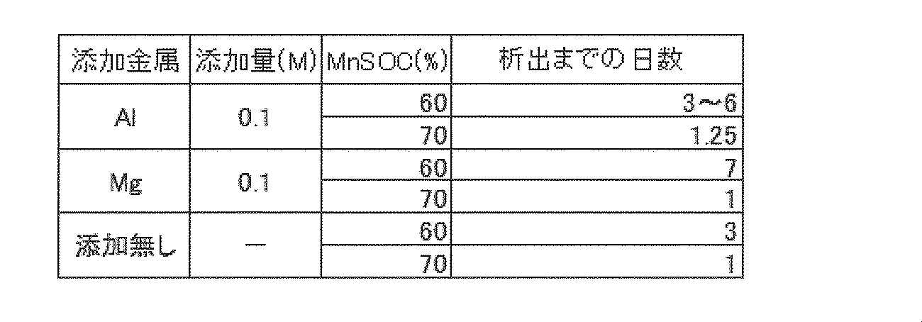
- the RF battery containing the Al-added sample is 3 to 6 days after standing when the charged state is 60%, and 1.25 days after standing when the charged state is 70%. The occurrence of precipitates was observed in each.
- generation of precipitates was observed in 7 days when the charged state was 60%, and in 1 day when the charged state was 70%.
- the state of charge was 70%, the generation of precipitates was observed in one day, but it was confirmed by visual observation that the precipitates were in a form easily dispersed. Is presumed to be finely divided.
- the precipitate becomes fine particles, it is easy to use as an RF battery because it is easily re-discharged.
- the number of days until deposition was 3 days and 1 day, respectively, when the charged state was 60% and 70%.
- a redox flow battery that performs charging and discharging by supplying a positive electrode electrolyte and a negative electrode electrolyte to a battery cell including a positive electrode, a negative electrode, and a diaphragm interposed between the two electrodes,
- the positive electrode electrolyte contains manganese ions
- the negative electrode electrolyte contains at least one metal ion selected from titanium ions, vanadium ions, chromium ions, and zinc ions, and an additive metal ion
- the additive metal ion contained in the negative electrode electrolyte contains at least one of aluminum ion, cadmium ion, indium ion, tin ion, antimony ion, iridium ion, gold ion, lead ion, bismuth ion, and magnesium ion. .
- the negative electrode electrolyte contains the added metal ion, so that (1) the battery reactivity of the metal ion functioning as the negative electrode active material can be increased (the reaction rate can be increased), (2 ) Depending on the ionic species, it may function as an active material, and (3) the effects of suppressing generation of hydrogen accompanying water decomposition are expected. Therefore, a redox flow battery with high energy density can be obtained.
- additive metal ions included in the negative electrode electrolyte for example, lithium ions, beryllium ions, sodium ions, potassium ions, calcium ions, scandium ions, nickel ions, gallium ions, Germanium ion, rubidium ion, strontium ion, yttrium ion, zirconium ion, niobium ion, technetium ion, rhodium ion, cesium ion, barium ion, lanthanoid ion except cerium ion, hafnium ion, tantalum ion, rhenium ion, osmium ion , Platinum ion, thallium ion, polonium ion, francium ion, radium ion, actinium ion, thorium ion, protoactinium ion Fine uranium ion and the like
- the redox flow battery of the present invention has a large capacity for the purpose of stabilizing fluctuations in power generation output, storing power when surplus generated power, load leveling, etc., for power generation of natural energy such as solar power generation and wind power generation. It can utilize suitably for this storage battery.
- the redox flow battery of the present invention can be suitably used as a large-capacity storage battery that is attached to a general power plant, a large commercial facility, etc., for the purpose of power supply reduction and load reduction. it can.
Landscapes
- Life Sciences & Earth Sciences (AREA)
- Engineering & Computer Science (AREA)
- Manufacturing & Machinery (AREA)
- Sustainable Development (AREA)
- Sustainable Energy (AREA)
- Chemical & Material Sciences (AREA)
- Chemical Kinetics & Catalysis (AREA)
- Electrochemistry (AREA)
- General Chemical & Material Sciences (AREA)
- Fuel Cell (AREA)
Abstract
Description
最初に本発明の実施形態の内容を列記して説明する。
(A)実施形態に係るレドックスフロー電池は、正極電極と、負極電極と、これら両電極間に介在される隔膜とを備える電池セルに正極電解液及び負極電解液を供給して充放電を行う。正極電解液は、マンガン(Mn)イオンと、添加金属イオンとを含有し、負極電解液は、チタン(Ti)イオン、バナジウム(V)イオン、クロム(Cr)イオン、及び亜鉛(Zn)イオンから選択される少なくとも一種の金属イオンを含有する。そして、正極電解液が含有する添加金属イオンは、アルミニウム(Al)イオン、カドミウム(Cd)イオン、インジウム(In)イオン、スズ(Sn)イオン、アンチモン(Sb)イオン、イリジウム(Ir)イオン、金(Au)イオン、鉛(Pb)イオン、ビスマス(Bi)イオン及びマグネシウム(Mg)イオンの少なくとも一種である。
(1)Alイオンが1価のAlイオン、2価のAlイオン、および3価のAlイオンの少なくとも一種
(2)Cdイオンが1価のCdイオン、および2価のCdイオンの少なくとも一方
(3)Inイオンが1価のInイオン、2価のInイオン、および3価のInイオンの少なくとも一種
(4)Snイオンが2価のSnイオン、および4価のSnイオンの少なくとも一方
(5)Sbイオンが3価のSbイオン、および5価のSbイオンの少なくとも一方
(6)Irイオンが1価のIrイオン、2価のIrイオン、3価のIrイオン、4価のIrイオン、5価のIrイオン、および6価のIrイオンの少なくとも一種
(7)Auイオンが1価のAuイオン、2価のAuイオン、3価のAuイオン、4価のAuイオン、および5価のAuイオンの少なくとも一種
(8)Pbイオンが2価のPbイオン、および4価のPbイオンの少なくとも一方
(9)Biイオンが3価のBiイオン、および5価のBiイオンの少なくとも一方
(10)Mgイオンが1価のMgイオン、および2価のMgイオンの少なくとも一方
本発明の実施形態に係るRF電解液を、以下の図面を参照しつつ説明する。なお、本発明はこれらの実施形態に限定されるものではなく、特許請求の範囲によって示され、特許請求の範囲と均等の意味及び範囲内でのすべての変更が含まれることが意図される。
実施形態に係るRF電池1は、代表的には、交流/直流変換器200や変電設備210を介して、発電部300(例えば、太陽光発電装置や風力発電装置、その他一般の発電所など)と負荷(ここでは、電力系統/需要家400)との間に接続される。そして、発電部300で発電した電力を充電して蓄え、又は、蓄えた電力を放電して電力系統/需要家400に供給する。このRF電池1は、従来のRF電池と同様に、電池セル100と、この電池セル100に電解液を供給する循環機構(タンク、導管、ポンプ)とを備える。
RF電池1における電池セル100は、正極電極104を内蔵する正極セル102と、負極電極105を内蔵する負極セル103と、両セル102,103を分離すると共にイオンを透過する隔膜101とを備える。正極セル102には、正極電解液を貯留する正極電解液用のタンク106が導管108,110を介して接続されている。負極セル103には、負極電解液を貯留する負極電解液用のタンク107が導管109,111を介して接続されている。また、導管108,109にはそれぞれ、両極の電解液を循環させるポンプ112,113が設けられている。電池セル100は、導管108~111とポンプ112,113によって、正極セル102(正極電極104)及び負極セル103(負極電極105)にそれぞれ正極電解液用のタンク106の正極電解液及び負極電解液用のタンク107の負極電解液を循環供給して、両極における電解液中の活物質となる金属イオン(本実施形態では、正極においてはMnイオン、負極においてはTiイオン)の価数変化に伴って充放電を行う。
正極電解液と負極電解液とには、それぞれに異なる構成の電解液を用いてもよいが、本実施形態のRF電池1に用いる正極電解液および負極電解液には、両電解液を共通の構成としている。この電解液は、複数の金属イオンを含有する。より詳細には、正極において活物質イオンとなるMnイオンと、負極において活物質イオンとなるTiイオンと、添加金属イオンとを含有する硫酸水溶液である。以下、この電解液につき、詳細に説明する。
活物質イオンは、電解液中に含まれる金属イオンであって、電子の受け渡しによる価数変化により電池反応に関与する。以下、両極における活物質イオンについて説明し、あわせて、正極電解液におけるTiイオン、および負極電解液におけるMnイオンについて説明する。
正極では、正極電解液中に含有されるMnイオンが活物質イオンとなり、Tiイオンは積極的には活物質として機能しない。このMnイオンは、電解液中において2価、3価、および4価の少なくとも一つの価数をとりうる。具体的には、放電時:2価のMnイオン(Mn2+)が存在し、充電時:3価のMnイオン(Mn3+)が存在し、充放電の繰り返しにより、両Mnイオンが存在する形態となる。よって、正極電解液が上記二つのMnイオンを含有することで標準酸化還元電位を高くすることができ、高い起電力のRF電池とすることができる。4価のMnは析出物(MnO2)と考えられるが、このMnO2は固体の析出物ではなく、電解液中に溶解したように見える安定な状態で存在していると考えられる。このようなMnO2は、放電時、2電子反応として、Mn2+に還元され(放電して)、即ち、MnO2が活物質として作用して、繰り返し使用できることで、電池容量の増加に寄与することがある。したがって、上記の各実施形態では、若干量(Mnイオンの総量(mol)に対して10%程度以下)の4価のMnの存在を許容する。
本実施形態において、負極では、負極電解液が含有するTiイオンが活物質イオンとなり、Mnイオンは積極的には活物質として機能しない。負極電解液では、放電時:4価のTiイオン(Ti4+、TiO2+など)が存在し、充電時:3価のTiイオン(Ti3+)が存在し、充放電の繰り返しにより、両Tiイオンが存在する形態となる。
両極の電解液に含有される活物質イオンの濃度はいずれも0.3M以上5M以下が好ましい。活物質イオンの濃度が0.3M未満では、大容量の蓄電池として十分なエネルギー密度(例えば、10kWh/m3程度)を確保することが難しいからである。よって、活物質イオンの濃度は高い方が好ましく、0.5M以上、更に1.0M以上がより好ましい。一方、本実施形態のように電解液の溶媒を酸の水溶液とする場合、酸濃度の上昇により活物質イオンの溶解度の低下を招くおそれがある。よって、一方の極における活物質イオンの合計濃度の上限は5M以下が好ましい。
添加金属イオンとは、正極電解液中で主として析出物の発生を抑制する機能を備え、積極的に活物質として機能しないものをいう。また、添加金属イオンが負極電解液に含有される場合には、(1)負極活物質として機能する金属イオンの電池反応性を高められる(反応速度を速められる)、(2)イオン種によっては活物質として機能することがある(3)水の分解に伴う水素の発生を抑制することができる、といった効果の少なくとも1つが期待される。
(1)Alイオン:1価のAlイオン、2価のAlイオン、および3価のAlイオンの少なくとも一種
(2)Cdイオン:1価のCdイオン、および2価のCdイオンの少なくとも一方
(3)Inイオン:1価のInイオン、2価のInイオン、および3価のInイオンの少なくとも一種
(4)Snイオン:2価のSnイオン、および4価のSnイオンの少なくとも一方
(5)Sbイオン:3価のSbイオン、および5価のSbイオンの少なくとも一方
(6)Irイオン:1価のIrイオン、2価のIrイオン、3価のIrイオン、4価のIrイオン、5価のIrイオン、および6価のIrイオンの少なくとも一種
(7)Auイオン:1価のAuイオン、2価のAuイオン、3価のAuイオン、4価のAuイオン、および5価のAuイオンの少なくとも一種
(8)Pbイオン:2価のPbイオン、および4価のPbイオンの少なくとも一方
(9)Biイオン:3価のBiイオン、および5価のBiイオンの少なくとも一方
(10)Mgイオン:1価のMgイオン、および2価のMgイオンの少なくとも一方
ここで、添加金属イオンは、電解液中で金属(固体)として存在する場合(0価の場合)、および上記以外の価数をとる場合を許容する。また、同一元素のイオンであって、価数が異なるイオンを含む場合がある。
本実施形態において、電解液が含有する金属イオンは、水溶性イオンが好適に利用できる。その場合、正極電解液及び負極電解液の溶媒には、水溶液を好適に利用することができる。特に、溶媒を硫酸や硫酸塩を含有する酸の水溶液とすると、(1)各種の金属イオンの安定性の向上、活物質イオンの反応性の向上、溶解度の向上が得られる場合がある、(2)Mnイオンのような電位が高い金属イオンを用いる場合でも、副反応が生じ難い(分解が生じ難い)、(3)イオン伝導度が高く、電池の内部抵抗が小さくなる、(4)塩酸を利用した場合と異なり、塩素ガスが発生しない、(5)硫酸塩などと水とを用いて電解液が容易に得られ、製造性に優れる、といった複数の効果が期待できる。この酸の水溶液を溶媒とする電解液には、例えば、硫酸アニオン(SO4 2-)が存在する。電解液の溶媒を酸溶液とする場合、酸の濃度を高めると、析出物の発生をある程度抑制できる。その反面、Mnイオンなどの各種の金属イオンの溶解度の低下や電解液の粘度の増加を招く恐れがある。したがって、各極の電解液中における酸の濃度は5M未満が好ましいと考えられ、特に4.5M以下、さらに1M以上4M以下が利用し易い。溶媒には、硫酸や硫酸塩の他、公知の酸や公知の塩を含む水溶液を利用することができる。
正極電極104及び負極電極105の材質は、例えば、カーボンファイバからなる不織布(カーボンフェルト)が挙げられる。カーボンフェルト製の電極を利用すると、(1)電解液に水溶液を用いた場合において充電時に酸素発生電位になっても、酸素ガスが発生し難い、(2)表面積が大きい、(3)電解液の流通性に優れる、といった効果がある。なお、他にも公知の電極を利用できる。
隔膜101は、例えば、陽イオン交換膜や陰イオン交換膜といったイオン交換膜が挙げられる。イオン交換膜は、(1)正極活物質の金属イオンと負極活物質の金属イオンとの隔離性に優れる、(2)H+イオン(電池内部の電荷担体)の透過性に優れる、といった効果があり、隔膜101に好適に利用することができる。上記以外にも、公知の隔膜を利用できる。
正極電解液用のタンク106、負極電解液用のタンク107、および導管108~111は、上記RF電解液が接触する部材である。部材(106~111)の構成材料には、密度(ASTM D 1505)が0.080g/cm3以上、0.960g/cm3以下の範囲内にあり、メルトフローレート(ASTM D 1238,測定条件:190℃、荷重2.16kg)が0.01g/10分以上、20g/10分以下の範囲内にあるエチレン単独重合体、あるいは上記の範囲の密度およびメルトフローレートのエチレン・αオレイン共重合体などが挙げられる。
[経時変化の観察]
試験例1では、実際の運用に供するRF電池を想定して、正極電解液に析出物が発生するかを観察した。まず、上記の実施形態と同様の構成のRF電池を試作した。このRF電池では、両電極に電極面積が9cm2のカーボンフェルトを、隔膜に陽イオン交換膜を用いた(後述する各試験例についても特に記述がない限り同様)。正極電解液および負極電解液には、それぞれに同一の(共通の)組成の電解液(試料)を用いた。まず、試料1として、硫酸マンガン、硫酸チタン、および硫酸を用いて水溶液を作製した。この試料1のマンガンイオン濃度は1.0M、チタンイオン濃度は1.0M、硫酸イオン濃度(合計濃度)は5.0Mである。さらに、試料1と硫酸ビスマス(III)とを用いて、試料2と試料3とを作製した。試料2は、ビスマスイオン濃度が0.1M、硫酸イオン濃度(合計濃度)が5.15M、試料3は、ビスマスイオン濃度が0.02M、硫酸イオン濃度(合計濃度)が5.03M、である。そして、上記のRF電池において、試料1から試料3をそれぞれ電解液とした場合における経時的な析出物の発生を観察した。各試料を用いたRF電池は、正極の充電状態(正極SOC)を90%とし、試料1を電解液としたRF電池では、充電状態が70%の場合についても観察した。RF電池の充電は、各試料を用いたRF電池を充電電流315mA、充電終了電圧2Vで充電することで行った。なお、充電状態は、下記により求めた。
・充電電気量(A・h)=充電電流(A)×充電時間(h)
・1電子反応の理論電気量(A・h)=電解液の体積(L)×マンガンイオンの濃度(mol/L)×ファラデーの定数:96,485(A・秒/mol)×1(電子)/3600

[電気化学測定]
試験例2では、上記の試験例1と同様の構成で0.785cm2のカーボンフェルト電極を用いたRF電池、並びに試料1および試料2を用いて、各極の酸化還元反応電流および酸化還元反応電位の測定を行った。酸化還元反応電流、および、酸化還元反応電位の測定は、ポテンショスタット/ガルバノスタット(北斗電工(株)製、HZ-5000)を用い、参照電極をAg/AgClとした三極式サイクリックボルタンメトリーにより行った。測定に際しては、まず、測定する極を作用極、対極をカウンター電極とし、測定する極側の電解液中に参照電極を設置した。そして、作用極の電解液は静止状態、対極を循環状態とした上で測定した。この際、掃引速度はいずれも3mV/sとした。この測定結果を表2に示す。なお、表2中の電流に関する項目の単位はmA/0.785cm2、電位に関する項目の単位はV(Vs Ag/AgCl)である。
[充電状態の検討]
試験例3では、上記の試験例1と同様の構成のRF電池を用いて、試料1および試料2をそれぞれ電解液に用いたRF電池の正極の充電状態を求めた。ただし、正極電解液を10ml、負極電解液を25ml、電極面積を9cm2とした点が試験例1と異なる。また、充電状態の調整は、上記の試験例1に記載の各項目の計算方法を基準にして行った。この結果を表3に示す。

[放電容量の測定]
試験例4では、試料2を電解液としたRF電池を用いて、充放電サイクル試験を行った。RF電池は上記の試験例1と同様の構成であるが、正極電解液が6ml、負極電解液が9ml、充電電流および放電電流が450mAである点が異なる。なお、充電側切替電圧(充電から放電に切り替える電圧)は1.5V、放電側切替電圧(放電から充電に切り替える電圧)は1.0Vとし、サイクル数=3とした。そして、各サイクルにおける電流効率(%)、電圧効率(%)、放電容量(Ah)をそれぞれ調べ、電流効率と電圧効率とから電池効率(%)を求めた。これらの値の求め方は下記のとおりである。
・電流効率(%)=(放電時間/充電時間)×100
・電圧効率(%)=放電時平均電圧(V)/充電時平均電圧(V)×100
・電池効率(%)=電流効率(%)×電圧効率(%)×0.01
・放電容量(Ah)=放電時間(時間)×電流(A)
[経時変化の観察]
試験例5では、実際の運用に供するRF電池を想定して、正極電解液に析出物が発生するかを観察した。まず、上記の実施形態と同様の構成のRF電池を試作した。
正極電解液として、Al添加試料、Mg添加試料、Sn添加試料、及び金属無添加試料を以下の通り作製した。
Al添加試料として、硫酸マンガン、硫酸チタン、硫酸、硫酸アルミニウムを用いて、マンガンイオン(2価)濃度が1.0M、チタンイオン(4価)濃度が1.0M、硫酸イオン濃度(合計濃度)が5.0M、Alイオン(3価)濃度が0.1Mの組成の電解液(ここでは水溶液)を用意した。
Mg添加試料として、硫酸マンガン、硫酸チタン、硫酸、硫酸マグネシウムを用いて、マンガンイオン(2価)濃度が1.0M、チタンイオン(4価)濃度が1.0M、硫酸イオン濃度(合計濃度)が5.0M、Mgイオン(2価)濃度が0.1Mの組成の電解液(ここでは水溶液)を用意した。
Sn添加試料として、硫酸マンガン、硫酸チタン、硫酸、硫酸スズを用いて、マンガンイオン(2価)濃度が1.0M、チタンイオン(4価)濃度が1.0M、硫酸イオン濃度(合計濃度)が5.0M、Snイオン(2価)濃度が0.05Mの組成の電解液(ここでは水溶液)を用意した。
金属無添加試料として、硫酸マンガン、硫酸チタン、硫酸を用いて、マンガンイオン(2価)濃度が1.0M、チタンイオン(4価)濃度が1.0M、硫酸イオン濃度(合計濃度)が5.0Mの組成の電解液(ここでは水溶液)を用意した。
充電電気量(A・h)=充電電流(A)×充電時間(h)
1電子反応の理論電気量(A・h)=電解液の体積(L)×マンガンイオンの濃度(mol/L)×ファラデーの定数:96,485(A・秒/mol)×1(電子)/3600
以上説明した本発明の実施形態に関連して、更に以下の付記を開示する。
正極電極と、負極電極と、これら両電極間に介在される隔膜とを備える電池セルに正極電解液及び負極電解液を供給して充放電を行うレドックスフロー電池であって、
前記正極電解液は、マンガンイオンを含有し、
前記負極電解液は、チタンイオン、バナジウムイオン、クロムイオン、及び亜鉛イオンから選択される少なくとも一種の金属イオンと、添加金属イオンとを含有し、
前記負極電解液が含有する添加金属イオンは、アルミニウムイオン、カドミウムイオン、インジウムイオン、スズイオン、アンチモンイオン、イリジウムイオン、金イオン、鉛イオン、ビスマスイオン及びマグネシウムイオンの少なくとも一種とを含有するレドックスフロー電池。
101 隔膜 102 正極セル 103 負極セル
104 正極電極 105 負極電極 106 正極電解液用のタンク
107 負極電解液用のタンク 108~111 導管
112,113 ポンプ
200 交流/直流変換器 210 変電設備
300 発電部 400 電力系統/需要家
Claims (11)
- 正極電極と、負極電極と、これら両電極間に介在される隔膜とを備える電池セルに正極電解液及び負極電解液を供給して充放電を行うレドックスフロー電池であって、
前記正極電解液は、マンガンイオンと、添加金属イオンとを含有し、
前記負極電解液は、チタンイオン、バナジウムイオン、クロムイオン、及び亜鉛イオンから選択される少なくとも一種の金属イオンを含有し、
前記正極電解液が含有する添加金属イオンは、アルミニウムイオン、カドミウムイオン、インジウムイオン、スズイオン、アンチモンイオン、イリジウムイオン、金イオン、鉛イオン、ビスマスイオン及びマグネシウムイオンの少なくとも一種であるレドックスフロー電池。 - 前記負極電解液は、更に、添加金属イオンを含有し、
前記負極電解液が含有する添加金属イオンは、アルミニウムイオン、カドミウムイオン、インジウムイオン、スズイオン、アンチモンイオン、イリジウムイオン、金イオン、鉛イオン、ビスマスイオン及びマグネシウムイオンの少なくとも一種である請求項1に記載のレドックスフロー電池。 - 前記正極電解液が、チタンイオンを含有する請求項1または請求項2に記載のレドックスフロー電池。
- 前記正極電解液が含有するチタンイオンの濃度が5M以下である請求項3に記載のレドックスフロー電池。
- 前記負極電解液が、マンガンイオンを含有する請求項1から請求項4のいずれか1項に記載にレドックスフロー電池。
- 前記負極電解液が含有するマンガンイオンの濃度が0.3M以上5M以下である請求項5に記載のレドックスフロー電池。
- 前記正極電解液が含有するマンガンイオンの濃度、および、前記負極電解液が含有する金属イオンの濃度の少なくとも一方が0.3M以上5M以下である請求項1から請求項6のいずれか1項に記載のレドックスフロー電池。
- 前記負極電解液がチタンイオンを含み、前記正極電解液が含有するマンガンイオンの濃度、および、前記負極電解液が含有するチタンイオンの濃度の少なくとも一方が0.3M以上5M以下である請求項1から請求項7のいずれか1項に記載のレドックスフロー電池。
- 前記正極電解液における添加金属イオンの合計濃度が0.001M以上1M以下である請求項1から請求項8のいずれか1項に記載のレドックスフロー電池。
- 前記正極電解液および前記負極電解液の少なくとも一方が含有する添加金属イオンまたは前記負極電解液が含有する添加金属イオンが、下記(1)から(10)の少なくとも1つを満たす請求項1から請求項9のいずれか1項に記載のレドックスフロー電池。
(1)前記アルミニウムイオンが1価のアルミニウムイオン、2価のアルミニウムイオン、および3価のアルミニウムイオンの少なくとも一種
(2)前記カドミウムイオンが1価のカドミウムイオン、および2価のカドミウムイオンの少なくとも一方
(3)前記インジウムイオンが1価のインジウムイオン、2価のインジウムイオン、および3価のインジウムイオンの少なくとも一種
(4)前記スズイオンが2価のスズイオン、および4価のスズイオンの少なくとも一方
(5)前記アンチモンイオンが3価のアンチモンイオン、および5価のアンチモンイオンの少なくとも一方
(6)前記イリジウムイオンが、1価のイリジウムイオン、2価のイリジウムイオン、3価のイリジウムイオン、4価のイリジウムイオン、5価のイリジウムイオン、および6価のイリジウムイオンの少なくとも一種
(7)前記金イオンが1価の金イオン、2価の金イオン、3価の金イオン、4価の金イオン、および5価の金イオンの少なくとも一種
(8)前記鉛イオンが2価の鉛イオン、および4価の鉛イオンの少なくとも一方
(9)前記ビスマスイオンが3価のビスマスイオン、および5価のビスマスイオンの少なくとも一方
(10)前記マグネシウムイオンが1価のマグネシウムイオン、および2価のマグネシウムイオンの少なくとも一方 - 前記マンガンイオンが2価のマンガンイオン、および3価のマンガンイオンの少なくとも一方であり、前記正極電解液及び前記負極電解液の少なくとも一方は、チタンイオンを含み、前記チタンイオンが3価のチタンイオン、および4価のチタンイオンの少なくとも一方である請求項1から請求項10のいずれか1項に記載のレドックスフロー電池。
Priority Applications (6)
| Application Number | Priority Date | Filing Date | Title |
|---|---|---|---|
| US14/773,112 US9972858B2 (en) | 2013-08-07 | 2014-08-04 | Redox flow battery |
| JP2014555893A JP5708963B1 (ja) | 2013-08-07 | 2014-08-04 | レドックスフロー電池 |
| KR1020157021176A KR102134055B1 (ko) | 2013-08-07 | 2014-08-04 | 레독스 플로우 전지 |
| CN201480012780.XA CN105009344B (zh) | 2013-08-07 | 2014-08-04 | 氧化还原液流电池 |
| EP14833636.5A EP3032628B1 (en) | 2013-08-07 | 2014-08-04 | Redox flow battery |
| AU2014303614A AU2014303614B2 (en) | 2013-08-07 | 2014-08-04 | Redox flow battery |
Applications Claiming Priority (2)
| Application Number | Priority Date | Filing Date | Title |
|---|---|---|---|
| JP2013-164541 | 2013-08-07 | ||
| JP2013164541 | 2013-08-07 |
Publications (1)
| Publication Number | Publication Date |
|---|---|
| WO2015019972A1 true WO2015019972A1 (ja) | 2015-02-12 |
Family
ID=52461305
Family Applications (1)
| Application Number | Title | Priority Date | Filing Date |
|---|---|---|---|
| PCT/JP2014/070422 Ceased WO2015019972A1 (ja) | 2013-08-07 | 2014-08-04 | レドックスフロー電池 |
Country Status (8)
| Country | Link |
|---|---|
| US (1) | US9972858B2 (ja) |
| EP (1) | EP3032628B1 (ja) |
| JP (2) | JP5708963B1 (ja) |
| KR (1) | KR102134055B1 (ja) |
| CN (1) | CN105009344B (ja) |
| AU (1) | AU2014303614B2 (ja) |
| TW (1) | TWI604658B (ja) |
| WO (1) | WO2015019972A1 (ja) |
Cited By (11)
| Publication number | Priority date | Publication date | Assignee | Title |
|---|---|---|---|---|
| WO2016104124A1 (ja) * | 2014-12-22 | 2016-06-30 | 住友電気工業株式会社 | レドックスフロー電池の運転方法、及びレドックスフロー電池システム |
| WO2016104237A1 (ja) * | 2014-12-22 | 2016-06-30 | 住友電気工業株式会社 | レドックスフロー電池 |
| WO2017006729A1 (ja) * | 2015-07-09 | 2017-01-12 | 住友電気工業株式会社 | レドックスフロー電池用電極、及びレドックスフロー電池システム |
| JP2018506138A (ja) * | 2015-04-08 | 2018-03-01 | エルジー・ケム・リミテッド | 高分子電解質膜、これを含む電気化学電池及びフロー電池、高分子電解質膜の製造方法、及びフロー電池用電解液 |
| US20190280324A1 (en) * | 2016-07-26 | 2019-09-12 | Sumitomo Electric Industries, Ltd. | Electrolyte for flow battery and flow battery system |
| JP2020509564A (ja) * | 2017-06-20 | 2020-03-26 | エルジー・ケム・リミテッド | 高分子電解質膜、これを含む電気化学電池及びフロー電池、高分子電解質膜用組成物、及び高分子電解質膜の製造方法 |
| US20220093955A1 (en) * | 2016-07-26 | 2022-03-24 | Sumitomo Electric Industries, Ltd. | Flow battery system |
| WO2022074911A1 (ja) * | 2020-10-06 | 2022-04-14 | 住友電気工業株式会社 | 電解液、及びレドックスフロー電池 |
| US20220181666A1 (en) * | 2019-03-20 | 2022-06-09 | Scott Waters | Electrochemical storage devices comprising chelated metals |
| CN115207427A (zh) * | 2022-07-20 | 2022-10-18 | 华中科技大学 | 一种基于氧化还原电对的新型热电-电化学电池及其制备 |
| CN119812419A (zh) * | 2025-03-13 | 2025-04-11 | 浙江师范大学 | 一种锰正极沉积/溶解胶体电解液及其应用 |
Families Citing this family (25)
| Publication number | Priority date | Publication date | Assignee | Title |
|---|---|---|---|---|
| JP6589633B2 (ja) * | 2015-12-25 | 2019-10-16 | 株式会社Gsユアサ | 鉛蓄電池 |
| AU2017290026A1 (en) * | 2016-07-01 | 2019-01-24 | Sumitomo Electric Industries, Ltd. | Redox flow battery, electrical quantity measurement system, and electrical quantity measurement method |
| JP6719728B2 (ja) * | 2016-07-26 | 2020-07-08 | 住友電気工業株式会社 | 電解液、電解槽用電解液、及び電解槽システム |
| CN106654314B (zh) * | 2016-11-04 | 2019-05-24 | 大连融科储能技术发展有限公司 | 电解液储罐及液流电池 |
| US10374239B2 (en) | 2016-12-29 | 2019-08-06 | Uchicago Argonne, Llc | Aqueous pyridinium cation-based redox flow batteries |
| US10553890B2 (en) | 2017-06-23 | 2020-02-04 | Uchicago Argonne, Llc | Aqueous redox flow batteries |
| US10424805B2 (en) | 2017-08-15 | 2019-09-24 | Uchicago Argonne, Llc | Benzothiophene-based redox molecules for flow battery |
| CN111373588B (zh) | 2017-11-06 | 2023-08-04 | Agc株式会社 | 适用于氧化还原液流电池的离子交换膜 |
| KR20190058136A (ko) * | 2017-11-21 | 2019-05-29 | 롯데케미칼 주식회사 | 레독스 흐름전지용 전해액 및 이를 포함하는 레독스 흐름전지 |
| US11177497B2 (en) * | 2018-03-12 | 2021-11-16 | Washington University | Redox flow battery |
| CN112042042B (zh) * | 2018-04-27 | 2024-09-20 | 京瓷株式会社 | 液流电池、液流电池系统和控制方法 |
| JP6820880B2 (ja) * | 2018-05-14 | 2021-01-27 | 株式会社バルカー | 実験装置、実験システム、プログラム、方法および学習方法 |
| CN108808053B (zh) * | 2018-06-22 | 2021-10-15 | 浙江裕源储能科技有限公司 | 一种锌镍液流储能电池 |
| EP3868814A4 (en) | 2018-10-19 | 2022-07-13 | Agc Inc. | ION EXCHANGE MEMBRANE AND REDOX FLOW CELL |
| KR102294549B1 (ko) | 2019-02-08 | 2021-08-30 | 건국대학교 산학협력단 | 전이후 금속 및 다공성 탄소를 포함하는 복합체, 이의 제조방법 및 이를 포함하는 레독스 흐름 전지 |
| CN110120543A (zh) * | 2019-04-08 | 2019-08-13 | 江苏大学 | 一种用于液流电池的低共熔溶剂、电解质及液流电池 |
| US11271237B2 (en) | 2019-07-29 | 2022-03-08 | Uchicago Argonne, Llc | Organic redox molecules for flow batteries |
| CN110729505A (zh) * | 2019-11-26 | 2020-01-24 | 中国科学院金属研究所 | 铁铬液流电池电解液及其应用 |
| CN110993999A (zh) * | 2019-11-26 | 2020-04-10 | 中国科学院金属研究所 | 一种用于铁铬液流电池的含添加剂的电解液及其应用 |
| CN110729506A (zh) * | 2019-11-26 | 2020-01-24 | 中国科学院金属研究所 | 一种含复合添加剂的铁铬液流电池电解液及其应用 |
| CN110911704A (zh) * | 2019-11-26 | 2020-03-24 | 中国科学院金属研究所 | 一种铁铬液流电池电解液及其应用 |
| CN113161630A (zh) * | 2021-05-24 | 2021-07-23 | 中国科学技术大学 | 水系二次电池及水系电解液 |
| CN113707925A (zh) * | 2021-08-24 | 2021-11-26 | 复旦大学 | 一种锡-锰水系液流电池 |
| JP2025517802A (ja) * | 2022-05-27 | 2025-06-10 | グリーン エナジー ストレージ エッセ.エッレ.エッレ. | レドックスフロー電池 |
| CN117154164B (zh) * | 2023-09-27 | 2024-03-22 | 中航国际科技成果转化基地(蚌埠)有限公司 | 一种液流电池组 |
Citations (2)
| Publication number | Priority date | Publication date | Assignee | Title |
|---|---|---|---|---|
| JPS579073A (en) * | 1980-06-17 | 1982-01-18 | Agency Of Ind Science & Technol | Bedox battery |
| WO2011111254A1 (ja) * | 2010-03-12 | 2011-09-15 | 住友電気工業株式会社 | レドックスフロー電池 |
Family Cites Families (14)
| Publication number | Priority date | Publication date | Assignee | Title |
|---|---|---|---|---|
| JPS4835792B1 (ja) | 1968-05-18 | 1973-10-30 | ||
| JPH09507950A (ja) * | 1993-11-17 | 1997-08-12 | ユニサーチ リミテッド | 安定電解液およびその製造方法と、レドックス電池の製造方法、および安定した電解液を含む電池 |
| US7820321B2 (en) * | 2008-07-07 | 2010-10-26 | Enervault Corporation | Redox flow battery system for distributed energy storage |
| CN102460812B (zh) * | 2009-05-28 | 2014-12-31 | 艾默吉电力系统股份有限公司 | 由原料制备流通电池电解质 |
| JP5713186B2 (ja) | 2010-03-12 | 2015-05-07 | 住友電気工業株式会社 | レドックスフロー電池 |
| WO2011111717A1 (ja) | 2010-03-12 | 2011-09-15 | 住友電気工業株式会社 | レドックスフロー電池 |
| DK2581976T3 (da) * | 2010-04-27 | 2014-05-12 | Sumitomo Electric Industries | Redox-flow-batteri |
| JP5007849B1 (ja) * | 2011-03-25 | 2012-08-22 | 住友電気工業株式会社 | レドックスフロー電池、及びその運転方法 |
| JP5769071B2 (ja) * | 2011-06-27 | 2015-08-26 | 住友電気工業株式会社 | レドックスフロー電池 |
| CN103620845B (zh) | 2011-06-27 | 2016-10-05 | 住友电气工业株式会社 | 氧化还原液流电池 |
| US8753761B2 (en) * | 2012-07-27 | 2014-06-17 | Sun Catalytix Corporation | Aqueous redox flow batteries comprising metal ligand coordination compounds |
| WO2014045337A1 (ja) * | 2012-09-18 | 2014-03-27 | 住友電気工業株式会社 | レドックスフロー電池 |
| CN105474446B (zh) | 2013-08-07 | 2018-07-03 | 住友电气工业株式会社 | 氧化还原液流电池 |
| US9812883B2 (en) * | 2014-02-18 | 2017-11-07 | Massachusetts Institute Of Technology | Materials for use with aqueous redox flow batteries and related methods and systems |
-
2014
- 2014-08-04 JP JP2014555893A patent/JP5708963B1/ja not_active Expired - Fee Related
- 2014-08-04 CN CN201480012780.XA patent/CN105009344B/zh not_active Expired - Fee Related
- 2014-08-04 US US14/773,112 patent/US9972858B2/en active Active
- 2014-08-04 WO PCT/JP2014/070422 patent/WO2015019972A1/ja not_active Ceased
- 2014-08-04 AU AU2014303614A patent/AU2014303614B2/en not_active Ceased
- 2014-08-04 EP EP14833636.5A patent/EP3032628B1/en not_active Not-in-force
- 2014-08-04 KR KR1020157021176A patent/KR102134055B1/ko not_active Expired - Fee Related
- 2014-08-07 TW TW103127091A patent/TWI604658B/zh not_active IP Right Cessation
-
2015
- 2015-02-17 JP JP2015028621A patent/JP6365883B2/ja not_active Expired - Fee Related
Patent Citations (3)
| Publication number | Priority date | Publication date | Assignee | Title |
|---|---|---|---|---|
| JPS579073A (en) * | 1980-06-17 | 1982-01-18 | Agency Of Ind Science & Technol | Bedox battery |
| WO2011111254A1 (ja) * | 2010-03-12 | 2011-09-15 | 住友電気工業株式会社 | レドックスフロー電池 |
| JP4835792B2 (ja) | 2010-03-12 | 2011-12-14 | 住友電気工業株式会社 | レドックスフロー電池 |
Non-Patent Citations (1)
| Title |
|---|
| See also references of EP3032628A4 |
Cited By (21)
| Publication number | Priority date | Publication date | Assignee | Title |
|---|---|---|---|---|
| US10615441B2 (en) | 2014-12-22 | 2020-04-07 | Sumitomo Electric Industries, Ltd. | Redox flow battery |
| WO2016104237A1 (ja) * | 2014-12-22 | 2016-06-30 | 住友電気工業株式会社 | レドックスフロー電池 |
| JPWO2016104237A1 (ja) * | 2014-12-22 | 2017-09-28 | 住友電気工業株式会社 | レドックスフロー電池 |
| WO2016104124A1 (ja) * | 2014-12-22 | 2016-06-30 | 住友電気工業株式会社 | レドックスフロー電池の運転方法、及びレドックスフロー電池システム |
| US10199672B2 (en) | 2014-12-22 | 2019-02-05 | Sumitomo Electric Industries, Ltd. | Method of operating redox flow battery, and redox flow battery system |
| TWI669849B (zh) * | 2014-12-22 | 2019-08-21 | 日商住友電氣工業股份有限公司 | Redox flow battery operation method and redox flow battery system |
| US10826100B2 (en) | 2015-04-08 | 2020-11-03 | Lg Chem, Ltd. | Polymer electrolyte membrane, electrochemical cell and flow cell comprising same, method for manufacturing polymer electrolyte membrane, and flow cell electrolyte |
| JP2018506138A (ja) * | 2015-04-08 | 2018-03-01 | エルジー・ケム・リミテッド | 高分子電解質膜、これを含む電気化学電池及びフロー電池、高分子電解質膜の製造方法、及びフロー電池用電解液 |
| JPWO2017006729A1 (ja) * | 2015-07-09 | 2018-04-19 | 住友電気工業株式会社 | レドックスフロー電池用電極、及びレドックスフロー電池システム |
| WO2017006729A1 (ja) * | 2015-07-09 | 2017-01-12 | 住友電気工業株式会社 | レドックスフロー電池用電極、及びレドックスフロー電池システム |
| US20190280324A1 (en) * | 2016-07-26 | 2019-09-12 | Sumitomo Electric Industries, Ltd. | Electrolyte for flow battery and flow battery system |
| US11233253B2 (en) * | 2016-07-26 | 2022-01-25 | Sumitomo Electric Industries, Ltd. | Electrolyte for flow battery and flow battery system |
| US20220093955A1 (en) * | 2016-07-26 | 2022-03-24 | Sumitomo Electric Industries, Ltd. | Flow battery system |
| AU2017304832B2 (en) * | 2016-07-26 | 2022-06-02 | Sumitomo Electric Industries, Ltd. | Electrolyte for Flow Battery and Flow Battery System |
| US11791488B2 (en) | 2016-07-26 | 2023-10-17 | Sumitomo Electric Industries, Ltd. | Flow battery system |
| JP2020509564A (ja) * | 2017-06-20 | 2020-03-26 | エルジー・ケム・リミテッド | 高分子電解質膜、これを含む電気化学電池及びフロー電池、高分子電解質膜用組成物、及び高分子電解質膜の製造方法 |
| US20220181666A1 (en) * | 2019-03-20 | 2022-06-09 | Scott Waters | Electrochemical storage devices comprising chelated metals |
| US12155103B2 (en) * | 2019-03-20 | 2024-11-26 | The Regents Of The University Of Colorado, A Body Corporate | Electrochemical storage devices comprising chelated metals |
| WO2022074911A1 (ja) * | 2020-10-06 | 2022-04-14 | 住友電気工業株式会社 | 電解液、及びレドックスフロー電池 |
| CN115207427A (zh) * | 2022-07-20 | 2022-10-18 | 华中科技大学 | 一种基于氧化还原电对的新型热电-电化学电池及其制备 |
| CN119812419A (zh) * | 2025-03-13 | 2025-04-11 | 浙江师范大学 | 一种锰正极沉积/溶解胶体电解液及其应用 |
Also Published As
| Publication number | Publication date |
|---|---|
| TW201530892A (zh) | 2015-08-01 |
| JP5708963B1 (ja) | 2015-04-30 |
| EP3032628A4 (en) | 2017-01-04 |
| US20160013506A1 (en) | 2016-01-14 |
| AU2014303614A1 (en) | 2015-09-17 |
| CN105009344A (zh) | 2015-10-28 |
| JP2015097219A (ja) | 2015-05-21 |
| US9972858B2 (en) | 2018-05-15 |
| EP3032628A1 (en) | 2016-06-15 |
| TWI604658B (zh) | 2017-11-01 |
| AU2014303614B2 (en) | 2017-09-14 |
| JPWO2015019972A1 (ja) | 2017-03-02 |
| KR102134055B1 (ko) | 2020-07-14 |
| KR20160037826A (ko) | 2016-04-06 |
| JP6365883B2 (ja) | 2018-08-01 |
| CN105009344B (zh) | 2018-12-11 |
| EP3032628B1 (en) | 2019-03-20 |
Similar Documents
| Publication | Publication Date | Title |
|---|---|---|
| JP5708963B1 (ja) | レドックスフロー電池 | |
| JP6390810B2 (ja) | レドックスフロー電池 | |
| US8288030B2 (en) | Redox flow battery | |
| JP6646896B2 (ja) | レドックスフロー電池 | |
| JP2016177868A (ja) | レドックスフロー電池 | |
| WO2011111717A1 (ja) | レドックスフロー電池 | |
| JP5713186B2 (ja) | レドックスフロー電池 | |
| JP2012079679A (ja) | レドックスフロー電池 | |
| JP2011233372A (ja) | レドックスフロー電池 | |
| JP2011210696A (ja) | レドックスフロー電池 | |
| JP5489008B2 (ja) | レドックスフロー電池 | |
| HK1158832B (en) | Redox flow battery |
Legal Events
| Date | Code | Title | Description |
|---|---|---|---|
| ENP | Entry into the national phase |
Ref document number: 2014555893 Country of ref document: JP Kind code of ref document: A |
|
| 121 | Ep: the epo has been informed by wipo that ep was designated in this application |
Ref document number: 14833636 Country of ref document: EP Kind code of ref document: A1 |
|
| ENP | Entry into the national phase |
Ref document number: 20157021176 Country of ref document: KR Kind code of ref document: A |
|
| WWE | Wipo information: entry into national phase |
Ref document number: 14773112 Country of ref document: US Ref document number: 2014833636 Country of ref document: EP |
|
| ENP | Entry into the national phase |
Ref document number: 2014303614 Country of ref document: AU Date of ref document: 20140804 Kind code of ref document: A |
|
| NENP | Non-entry into the national phase |
Ref country code: DE |