WO2015019990A1 - 空気入りタイヤ - Google Patents
空気入りタイヤ Download PDFInfo
- Publication number
- WO2015019990A1 WO2015019990A1 PCT/JP2014/070451 JP2014070451W WO2015019990A1 WO 2015019990 A1 WO2015019990 A1 WO 2015019990A1 JP 2014070451 W JP2014070451 W JP 2014070451W WO 2015019990 A1 WO2015019990 A1 WO 2015019990A1
- Authority
- WO
- WIPO (PCT)
- Prior art keywords
- tire
- tread
- carcass
- distance
- bead
- Prior art date
- Legal status (The legal status is an assumption and is not a legal conclusion. Google has not performed a legal analysis and makes no representation as to the accuracy of the status listed.)
- Ceased
Links
Images




Classifications
-
- B—PERFORMING OPERATIONS; TRANSPORTING
- B60—VEHICLES IN GENERAL
- B60C—VEHICLE TYRES; TYRE INFLATION; TYRE CHANGING; CONNECTING VALVES TO INFLATABLE ELASTIC BODIES IN GENERAL; DEVICES OR ARRANGEMENTS RELATED TO TYRES
- B60C3/00—Tyres characterised by the transverse section
- B60C3/04—Tyres characterised by the transverse section characterised by the relative dimensions of the section, e.g. low profile
-
- B—PERFORMING OPERATIONS; TRANSPORTING
- B60—VEHICLES IN GENERAL
- B60C—VEHICLE TYRES; TYRE INFLATION; TYRE CHANGING; CONNECTING VALVES TO INFLATABLE ELASTIC BODIES IN GENERAL; DEVICES OR ARRANGEMENTS RELATED TO TYRES
- B60C11/00—Tyre tread bands; Tread patterns; Anti-skid inserts
-
- B—PERFORMING OPERATIONS; TRANSPORTING
- B60—VEHICLES IN GENERAL
- B60C—VEHICLE TYRES; TYRE INFLATION; TYRE CHANGING; CONNECTING VALVES TO INFLATABLE ELASTIC BODIES IN GENERAL; DEVICES OR ARRANGEMENTS RELATED TO TYRES
- B60C11/00—Tyre tread bands; Tread patterns; Anti-skid inserts
- B60C11/0008—Tyre tread bands; Tread patterns; Anti-skid inserts characterised by the tread rubber
-
- B—PERFORMING OPERATIONS; TRANSPORTING
- B60—VEHICLES IN GENERAL
- B60C—VEHICLE TYRES; TYRE INFLATION; TYRE CHANGING; CONNECTING VALVES TO INFLATABLE ELASTIC BODIES IN GENERAL; DEVICES OR ARRANGEMENTS RELATED TO TYRES
- B60C11/00—Tyre tread bands; Tread patterns; Anti-skid inserts
- B60C11/0083—Tyre tread bands; Tread patterns; Anti-skid inserts characterised by the curvature of the tyre tread
-
- B—PERFORMING OPERATIONS; TRANSPORTING
- B60—VEHICLES IN GENERAL
- B60C—VEHICLE TYRES; TYRE INFLATION; TYRE CHANGING; CONNECTING VALVES TO INFLATABLE ELASTIC BODIES IN GENERAL; DEVICES OR ARRANGEMENTS RELATED TO TYRES
- B60C11/00—Tyre tread bands; Tread patterns; Anti-skid inserts
- B60C11/03—Tread patterns
- B60C11/0327—Tread patterns characterised by special properties of the tread pattern
- B60C11/0332—Tread patterns characterised by special properties of the tread pattern by the footprint-ground contacting area of the tyre tread
-
- B—PERFORMING OPERATIONS; TRANSPORTING
- B60—VEHICLES IN GENERAL
- B60C—VEHICLE TYRES; TYRE INFLATION; TYRE CHANGING; CONNECTING VALVES TO INFLATABLE ELASTIC BODIES IN GENERAL; DEVICES OR ARRANGEMENTS RELATED TO TYRES
- B60C13/00—Tyre sidewalls; Protecting, decorating, marking, or the like, thereof
-
- B—PERFORMING OPERATIONS; TRANSPORTING
- B60—VEHICLES IN GENERAL
- B60C—VEHICLE TYRES; TYRE INFLATION; TYRE CHANGING; CONNECTING VALVES TO INFLATABLE ELASTIC BODIES IN GENERAL; DEVICES OR ARRANGEMENTS RELATED TO TYRES
- B60C15/00—Tyre beads, e.g. ply turn-up or overlap
-
- B—PERFORMING OPERATIONS; TRANSPORTING
- B60—VEHICLES IN GENERAL
- B60C—VEHICLE TYRES; TYRE INFLATION; TYRE CHANGING; CONNECTING VALVES TO INFLATABLE ELASTIC BODIES IN GENERAL; DEVICES OR ARRANGEMENTS RELATED TO TYRES
- B60C15/00—Tyre beads, e.g. ply turn-up or overlap
- B60C15/0009—Tyre beads, e.g. ply turn-up or overlap features of the carcass terminal portion
- B60C15/0036—Tyre beads, e.g. ply turn-up or overlap features of the carcass terminal portion with high ply turn-up, i.e. folded around the bead core and terminating radially above the point of maximum section width
-
- B—PERFORMING OPERATIONS; TRANSPORTING
- B60—VEHICLES IN GENERAL
- B60C—VEHICLE TYRES; TYRE INFLATION; TYRE CHANGING; CONNECTING VALVES TO INFLATABLE ELASTIC BODIES IN GENERAL; DEVICES OR ARRANGEMENTS RELATED TO TYRES
- B60C3/00—Tyres characterised by the transverse section
-
- B—PERFORMING OPERATIONS; TRANSPORTING
- B60—VEHICLES IN GENERAL
- B60C—VEHICLE TYRES; TYRE INFLATION; TYRE CHANGING; CONNECTING VALVES TO INFLATABLE ELASTIC BODIES IN GENERAL; DEVICES OR ARRANGEMENTS RELATED TO TYRES
- B60C9/00—Reinforcements or ply arrangement of pneumatic tyres
- B60C9/02—Carcasses
-
- B—PERFORMING OPERATIONS; TRANSPORTING
- B60—VEHICLES IN GENERAL
- B60C—VEHICLE TYRES; TYRE INFLATION; TYRE CHANGING; CONNECTING VALVES TO INFLATABLE ELASTIC BODIES IN GENERAL; DEVICES OR ARRANGEMENTS RELATED TO TYRES
- B60C11/00—Tyre tread bands; Tread patterns; Anti-skid inserts
- B60C11/0008—Tyre tread bands; Tread patterns; Anti-skid inserts characterised by the tread rubber
- B60C2011/0016—Physical properties or dimensions
- B60C2011/0033—Thickness of the tread
-
- B—PERFORMING OPERATIONS; TRANSPORTING
- B60—VEHICLES IN GENERAL
- B60C—VEHICLE TYRES; TYRE INFLATION; TYRE CHANGING; CONNECTING VALVES TO INFLATABLE ELASTIC BODIES IN GENERAL; DEVICES OR ARRANGEMENTS RELATED TO TYRES
- B60C9/00—Reinforcements or ply arrangement of pneumatic tyres
- B60C9/02—Carcasses
- B60C9/0292—Carcass ply curvature
-
- Y—GENERAL TAGGING OF NEW TECHNOLOGICAL DEVELOPMENTS; GENERAL TAGGING OF CROSS-SECTIONAL TECHNOLOGIES SPANNING OVER SEVERAL SECTIONS OF THE IPC; TECHNICAL SUBJECTS COVERED BY FORMER USPC CROSS-REFERENCE ART COLLECTIONS [XRACs] AND DIGESTS
- Y02—TECHNOLOGIES OR APPLICATIONS FOR MITIGATION OR ADAPTATION AGAINST CLIMATE CHANGE
- Y02T—CLIMATE CHANGE MITIGATION TECHNOLOGIES RELATED TO TRANSPORTATION
- Y02T10/00—Road transport of goods or passengers
- Y02T10/80—Technologies aiming to reduce greenhouse gasses emissions common to all road transportation technologies
- Y02T10/86—Optimisation of rolling resistance, e.g. weight reduction
Definitions
- the present invention relates to a pneumatic tire having improved fuel efficiency while maintaining uneven wear at the shoulder.
- Tire rolling resistance and air resistance are factors of tire fuel efficiency.
- the rolling resistance of tires is mainly due to energy loss due to repeated deformation of rubber during driving.
- rubber with low energy loss small tan ⁇ should be used for tread rubber. Has been done.
- a narrow and large bead diameter tire with a reduced tire cross-section width and a larger bead diameter reduces energy loss at the tread and sidewalls and reduces tire mass. It has been found that fuel efficiency is greatly improved by reducing air resistance.
- the present invention is based on the regulation of the tire axial distribution of the tread thickness from the carcass to the outer surface of the tread portion in a narrow and large bead tire.
- An object of the present invention is to provide a pneumatic tire capable of suppressing shoulder uneven wear while further improving the effect of improving the property.
- the present invention is a pneumatic tire comprising a carcass that extends from a tread portion through a sidewall portion to a bead core of a bead portion,
- the tire cross-sectional width Wt satisfies the following expressions (1) and (2), Wt ⁇ ⁇ 0.7257 ⁇ (Db) 2 + 42.763 ⁇ Db ⁇ 339.67 ⁇ (1) Wt ⁇ ⁇ 0.7257 ⁇ (Db) 2 + 48.568 ⁇ Db ⁇ 552.33 ⁇
- the ratio of the tire axial direction distance from the tire equator plane to the tire axial distance L from the tire equatorial plane to the maximum width position of the carcass is y, and the tire axial position at Py is the tire axial position at each tire axial position Py.
- f (y) 1 ⁇ t (y) / t (0) ⁇ (3)
- f (y) 1 ⁇ t (y) / t (0) ⁇ (3)
- y 0.4
- f (y) is in the range of 0.03 to 0.06
- the tire outer diameter Dt (unit: mm) satisfies the following expressions (4) and (5).
- each part of the tire is values specified when the bead part is held in accordance with the rim width defined by the tire size in a non-rim assembled state.
- the pneumatic tire of the present invention is formed as a tire having a narrow and large bead diameter in which the tire cross-sectional width Wt satisfies the expressions (1) and (2). Therefore, it is possible to achieve a reduction in the amount of energy loss in the tread portion and the sidewall portion, a reduction in tire mass, and a reduction in air resistance, thereby improving fuel efficiency.
- the tread contact width is inevitably narrow, which causes a problem that shoulder wear occurs during turning.
- the tread thickness distribution curve f (y) determined by the above equation (3) by specifying the tread thickness distribution curve f (y) determined by the above equation (3), the effect of improving the fuel efficiency described above is further enhanced, and the tire is unique to a tire having a narrow and large bead diameter. Suppress uneven shoulder wear.
- the contact length is usually long and the contact pressure is high. This is because, when a load is applied, the tread portion is bent and deformed near the ground contact end, and at the tire axial position P 0.4 , the tread rubber is compressed from the tire circumferential direction and the tire axial direction, and the tread rubber is collected. Cause to come. If the contact length is long and the contact pressure is high, there is a disadvantage in uneven wear at the shoulder during turning.
- the tire tread thickness t (0) at the tire equator plane is at the tire axial position P0.4 .
- the tread thickness t (0.4) is still sufficiently thick, and the tread rubber is also thickened by compression from the outside in the tire axial direction.
- the contact pressure is still high, and uneven wear at the shoulder portion is not sufficiently improved during turning.
- FIG. (A) to (D) are plan views showing the contact surface shapes of Examples 3A and 3B and Comparative Examples 3A and 3B.
- the pneumatic tire 1 of the present embodiment includes a carcass 6 that extends from the tread portion 2 through the sidewall portion 3 to the bead core 5 of the bead portion 4.
- the case where the said pneumatic tire 1 is a radial tire for passenger cars is illustrated.
- the carcass 6 is formed of one or more carcass plies 6A, in this example, one carcass ply 6A in which carcass cords are arranged at an angle of, for example, 75 to 90 ° with respect to the tire equatorial plane Co.
- the carcass ply 6 ⁇ / b> A has ply folding portions 6 b that are folded from the inner side to the outer side in the tire axial direction around the bead core 5 at both ends of the toroidal ply main body portion 6 a straddling the bead cores 5 and 5.
- a bead apex rubber 8 for bead reinforcement that extends from the bead core 5 outward in the tire radial direction is disposed.
- a belt layer 7 is disposed outside the carcass 6 in the tire radial direction and inside the tread portion 2.
- the belt layer 7 is formed of two or more belt plies 7A and 7B in this example, in which belt cords are arranged at an angle of, for example, 10 to 35 ° with respect to the tire equatorial plane Co.
- the belt cords cross each other between the plies. As a result, the belt rigidity is increased and the tread portion 2 is strongly reinforced with a hoop effect.
- a band layer 9 in which a band cord is spirally wound at an angle of 5 degrees or less with respect to the tire equatorial plane Co for the purpose of enhancing high-speed durability is arranged.
- the band layer 9 a pair of left and right edge band plies that covers only the outer end portion in the tire axial direction of the belt layer 7 and a full band ply that covers substantially the entire width of the belt layer 7 can be used as appropriate.
- the band layer 9 consists of one full band ply is illustrated.
- the pneumatic tire 1 satisfies the following expressions (1) and (2) when the tire cross-sectional width is Wt (unit: mm) and the bead diameter is Db (unit: inch). It is formed as a tire with a narrow and large bead diameter.
- the region Y1 satisfying the expressions (1) and (2) is outside the range of the conventional tire indicated by the plot, and the average relation Ka indicated by the expression (A) is expressed by the tire cross-sectional width. It is arranged at a position where Wt is translated in a small direction and bead diameter Db is translated in a large direction. That is, a tire satisfying the above formulas (1) and (2) has a narrow and large bead diameter in which the tire cross-sectional width Wt is reduced and the bead diameter Db is increased as compared with a conventional tire having the same tire outer diameter. Tire.
- Such a tire has a narrow tread width due to a narrow tire cross-sectional width, and accordingly, a rubber amount of the tread rubber also decreases. Therefore, the amount of energy loss due to the tread rubber is relatively reduced, and the tire mass is also reduced.
- the exposed area of the tire exposed downward from the lower end of the bumper is also reduced with the tire cross-sectional width. Therefore, the air resistance of the tire during traveling can be reduced.
- the bead diameter is larger than that of a conventional tire having the same tire outer diameter, the side wall region where the deformation during running is large is narrowed. As a result, the amount of energy loss in the sidewall portion 3 is reduced, and the tire mass is also reduced.
- the fuel consumption performance of the tire can be improved by reducing the energy loss in the tread portion 2 and the sidewall portion 3, reducing the tire mass, and reducing the air resistance.
- the tire outer diameter Dt (unit: mm) satisfies the following expressions (4) and (5).
- the average relationship Kb shown in the expression (B) is arranged at a position where the tire outer diameter Dt is translated in the large direction. Is done.
- a tire that further satisfies the expressions (4) and (5) is a tire having a narrow width, a large bead diameter, and a large tire outer diameter Dt.
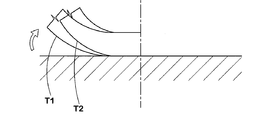
- the tire T1 having a relatively large tire outer diameter Dt has less bending deformation in the circumferential direction at the contact portion than the tire T2 having a small tire outer diameter Dt. Therefore, the amount of energy loss is small, and it is effective in reducing rolling resistance. Therefore, when it deviates from the formula (5), the rolling resistance cannot be reduced by increasing the tire diameter.
- the tread ground contact width decreases as well as the tire cross-sectional width. Therefore, when a load is applied, there is a problem that the contact length becomes long or the contact pressure becomes high at the shoulder portion of the tire, and shoulder wear occurs during turning.
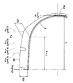
- the distribution in the tire axial direction of the tread thickness t (y) from the carcass 6 to the outer surface 2S of the tread portion 2 is regulated.
- f (y) 1 ⁇ t (y) / t (0) ⁇ (3)
- t (y) means the tread thickness that is the distance in the tire radial direction from the outer surface of the carcass 6 to the outer surface 2S of the tread portion 2 at the tire axial direction position Py.
- the tire axial direction position Py is a tire axis from the tire equatorial plane Co to the tire axial direction distance L, where L is a tire axial direction distance from the tire equatorial plane Co to the maximum width position Pm of the carcass 6. It means the tire axial position where the directional distance ratio is y. That is, for example, when the tire axial distance from the tire equatorial plane Co is 0.4 times the distance L, the tire axial position is P 0.4 .
- the maximum width position Pm of the carcass 6 is defined as a position where the outer surface of the ply main body portion 6a of the carcass 6 protrudes most outward in the tire axial direction.
- the tread thickness distribution curve f (y) is a tread at a position (corresponding to the tire axial direction position P 0.) Of the tread thickness t (0) at each axially position Py of the tire equatorial plane Co
- the rate of change of thickness t (y) is shown.
- 6 shows tread thickness distribution curves f (y) in tires of Examples 3A to 3C and Comparative Examples 3A to 3C described in Table 2 described later.
- 7A to 7D show the shapes of the ground planes of Examples 3A and 3B and Comparative Examples 3A and 3B. In the contact surface shape, the color of the portion where the contact pressure is high is shown darkly.
- the contact length is usually long and the contact pressure is high. This is because, when a load is applied, the tread rubber is bent and deformed near the ground contact end, and the tread rubber is compressed from the tire circumferential direction and the tire axial direction at the tire axial direction position P 0.4 , and the tread rubber is collected. Cause. If the contact length is long and the contact pressure is high, there is a disadvantage in wear on the shoulder during turning. In particular, as in Comparative Example 3A, when the tread thickness t (y) is uniformly distributed in the tire axial direction and the tread thickness distribution curve f (y) is a horizontal line with f (y) ⁇ 0, As shown in FIG. 7A, the contact length of the shoulder portion is extremely long and the contact pressure becomes high.
- the rate of change does not satisfy this, for example, when the rate of change is linear (for example, Comparative Example 3C), the tread thickness t (y) is too thin on the tire equator side and too thick on the shoulder side.
- the rate of change of f (y) is the slope of the tangent line of the curve f (y) and corresponds to a value (d (f (y)) / dy) obtained by differentiating f (y) by y.
- it is larger than 0.105 it becomes too thin, and the ground pressure distribution tends to be non-uniform respectively.
- the effect of improving uneven wear at the shoulder portion tends to be reduced.
- a pneumatic tire having the internal structure shown in FIG. 1 was prototyped according to the specifications shown in Table 1, and the rolling resistance, air resistance, and riding comfort performance of each sample tire were tested.
- Example 3 was used as a reference tire 3A (Example 3A), and a tire in which only the tread thickness distribution was changed in accordance with the specifications shown in Table 2 was prototyped. Rolling resistance at that time and wear at the shoulder (Sh wear) And tested.
- the tires of the examples have improved fuel efficiency (rolling resistance and air resistance) while maintaining wearability at the shoulder portion.
Landscapes
- Engineering & Computer Science (AREA)
- Mechanical Engineering (AREA)
- Tires In General (AREA)
Abstract
ショルダー部での摩耗性を維持しながら燃費性(転がり抵抗及び空気抵抗)を改善する。タイヤ断面巾をWt(単位:mm)、ビード径をDb(単位:インチ)としたとき、次式(1)、(2)を充足する。 Wt≦ -0.7257×(Db)2 + 42.763×Db - 339.67 ---(1) Wt≧ -0.7257×(Db)2 + 48.568×Db - 552.33 ---(2) また、タイヤ赤道面からカーカスの最大幅位置までのタイヤ軸方向距離Lに対するタイヤ赤道面からのタイヤ軸方向距離の比がyであるタイヤ軸方向位置をPy、各タイヤ軸方向位置Pyにおける、カーカスの外表面からトレッド部の外表面までのタイヤ半径方向距離であるトレッド厚さをt(y)としたとき、次式(3)で示されるトレッド厚さ分布曲線f(y)において、y=0.4の時の、f(y)は0.03~0.06の範囲であり、f(y)の変化率はy=0.4まで増加し、その後減少する。 f(y)=1-t(y)/t(0) ---(3)
Description
本発明は、ショルダー部での偏摩耗性を維持しながら燃費性を改善した空気入りタイヤに関する。
タイヤにおける燃費性の要因として、タイヤの転がり抵抗および空気抵抗がある。このうちタイヤの転がり抵抗は、走行時におけるゴムの繰返し変形に伴うエネルギー損失が主原因であり、この転がり抵抗を減じるために、トレッドゴムにエネルギー損失の少ない(tanδが小さい)ゴムを使用することが行われている。
しかしエネルギー損失が小さいゴムを使用した場合、転がり抵抗は減じるものの、グリップ性能(特に、ウェットグリップ性能)が低下し、また耐摩耗性も悪化するという問題がある。下記の特許文献1、2などに示されるように、耐摩耗性を向上させつつ転がり抵抗を減じたトレッドゴム組成物の研究が進められている。しかしゴム組成物による改善だけでは限界があり、ゴム組成物以外からの低転がり抵抗性へのアプローチが強く望まれている。
このような状況に鑑み、本発明者が研究を行った結果、以下のことを究明し得た。タイヤ外径が同一のタイヤにおいてタイヤ断面巾を減じた場合、それに伴いトレッド巾も減少する。そのため、トレッドゴムのゴム量も少なくなる。その結果、トレッドゴムによるエネルギー損失量が減じ、かつタイヤの軽量化も図られる。又車両を前面視したとき、バンパー下端から下方に露出するタイヤの露出面積も、タイヤ断面巾とともに減じるため、タイヤの空気抵抗を減じることができる。
又、タイヤ外径が同一のタイヤにおいて、ビード径を大きくした場合、走行時の変形が大きいサイドウォール領域が狭くなる。その結果、サイドウォール部におけるエネルギー損失量の低減、及びタイヤの軽量化が図られる。
従って、タイヤ外径が同一のタイヤにおいて、タイヤ断面巾を減じかつビード径を大きくした巾狭・大ビード径のタイヤにおいては、トレッド部及びサイドウォール部におけるエネルギー損失量の低減、タイヤ質量の低減、及び空気抵抗の低減により、燃費性が大幅に改善されることが判明した。
しかしながら、本発明者のさらなる研究の結果、前述の巾狭・大ビード径のタイヤにおいては、タイヤ断面巾とともにトレッド接地巾も減少する。そのため荷重負荷時、タイヤのショルダー部で、接地長さが長くなったり接地圧が高くなり、旋回時においてショルダー摩耗が発生するという解決すべき新たな問題があることが判明した。
本発明は、巾狭・大ビード径のタイヤにおいて、カーカスからトレッド部の外表面までのトレッド厚さのタイヤ軸方向の分布を規制することを基本として、巾狭・大ビード径のタイヤにおける燃費性の改善効果をさらに高めながら、ショルダー偏摩を抑制しうる空気入りタイヤを提供することを課題としている。
本発明は、トレッド部からサイドウォール部をへてビード部のビードコアに至るカーカスを具えた空気入りタイヤであって、
タイヤ断面巾をWt(単位:mm)、ビード径をDb(単位:インチ)としたとき、前記タイヤ断面巾Wtが次式(1)、(2)を充足するとともに、
Wt≦ -0.7257×(Db)2 + 42.763×Db - 339.67 ---(1)
Wt≧ -0.7257×(Db)2 + 48.568×Db - 552.33 ---(2)
タイヤ赤道面から前記カーカスの最大幅位置までのタイヤ軸方向距離Lに対するタイヤ赤道面からのタイヤ軸方向距離の比がyであるタイヤ軸方向位置をPy、各タイヤ軸方向位置Pyにおける、カーカスの外表面からトレッド部の外表面までのタイヤ半径方向距離であるトレッド厚さをt(y)としたとき、次式(3)で示されるトレッド厚さ分布曲線f(y)において、
f(y)=1-t(y)/t(0) ---(3)
y=0.4の時の、f(y)は0.03~0.06の範囲であり、
しかも、f(y)の変化率(d(f(y))/dy)はy=0.4まで増加し、その後減少することを特徴としている。
タイヤ断面巾をWt(単位:mm)、ビード径をDb(単位:インチ)としたとき、前記タイヤ断面巾Wtが次式(1)、(2)を充足するとともに、
Wt≦ -0.7257×(Db)2 + 42.763×Db - 339.67 ---(1)
Wt≧ -0.7257×(Db)2 + 48.568×Db - 552.33 ---(2)
タイヤ赤道面から前記カーカスの最大幅位置までのタイヤ軸方向距離Lに対するタイヤ赤道面からのタイヤ軸方向距離の比がyであるタイヤ軸方向位置をPy、各タイヤ軸方向位置Pyにおける、カーカスの外表面からトレッド部の外表面までのタイヤ半径方向距離であるトレッド厚さをt(y)としたとき、次式(3)で示されるトレッド厚さ分布曲線f(y)において、
f(y)=1-t(y)/t(0) ---(3)
y=0.4の時の、f(y)は0.03~0.06の範囲であり、
しかも、f(y)の変化率(d(f(y))/dy)はy=0.4まで増加し、その後減少することを特徴としている。
本発明に係る前記空気入りタイヤでは、タイヤ外径Dt(単位:mm)が、次式(4)、(5)を充足することが好ましい。
Dt≦ 59.078×Wt0.498 ---(4)
Dt≧ 59.078×Wt0.467 ---(5)
Dt≦ 59.078×Wt0.498 ---(4)
Dt≧ 59.078×Wt0.467 ---(5)
本発明に係る前記空気入りタイヤでは、y=0.3の時の、f(y)は0.01~0.03の範囲であり、かつ y=0.5の時の、f(y)は0.06~0.105の範囲であるのが好ましい。
本明細書では、特に断りがない限り、タイヤの各部の寸法は、非リム組状態において、タイヤサイズで規定されるリム巾に合わせてビード部を保持したときに特定される値とする。
本発明の空気入りタイヤは、叙上の如く、タイヤ断面巾Wtが前式(1)、(2)を充足する巾狭・大ビード径のタイヤとして形成される。そのため、トレッド部及びサイドウォール部におけるエネルギー損失量の低減、タイヤ質量の低減、及び空気抵抗の低減を達成でき、燃費性を改善させることが可能となる。
しかし前記巾狭・大ビード径のタイヤにおいては、トレッド接地巾が必然的に狭くなるため、旋回時においてショルダー摩耗が発生するという問題を招く。
そこで本発明では、前式(3)で定まるトレッド厚さ分布曲線f(y)を特定することで、前述の燃費性の改善効果をさらに高めながら、巾狭・大ビード径のタイヤに特有のショルダー偏摩耗を抑制する。
ここで、y=0.4のタイヤ軸方向位置P0.4では、通常、接地長が長く、かつ接地圧が高くなる。これは、荷重負荷時、トレッド部が接地端付近で曲げ変形し、前記タイヤ軸方向位置P0.4において、トレッドゴムにタイヤ周方向とタイヤ軸方向とから圧縮が働き、トレッドゴムが集まって来ることが原因する。そして接地長が長く、接地圧が高くなると、旋回時、ショルダー部での偏摩耗に不利をもたらす。
特に、トレッド厚さt(y)をタイヤ軸方向に均一に分布させた場合、即ち、トレッド厚さ分布曲線f(y)においてf(y)≒0の場合、この傾向が顕著になる。そして、f(y)がyとともに増加する曲線とすることで、この傾向は改善される。
しかしながら、y=0.4の時のf(y)の値が0.03より小さいと、タイヤ赤道面でのトレッド厚さt(0)に対して、タイヤ軸方向位置P0.4でのトレッド厚さt(0.4)がまだ十分厚く、しかもタイヤ軸方向外側からの圧縮によってトレッドゴムも厚くなる。その結果、接地圧が依然として高く、旋回時、ショルダー部での偏摩耗が十分改善されない。又、y=0.4の時のf(y)の値が0.06より大きいと、タイヤ赤道面側の接地長が長く、かつショルダー側の接地長が短くなりすぎる。その結果、フリーローリング時にショルダー部で滑りが大きくなって、直進走行においてショルダー部で偏摩耗が発生傾向となる。
又、y=0.4の時のf(y)の値が0.03~0.06の範囲内にある場合にも、f(y)の変化率は、y=0.4まで増加し、その後減少することが必要である。前記変化率がこれを満たしていない場合、例えば変化率がリニアな場合、トレッド厚さt(y)が、タイヤ赤道側で薄すぎ、かつショルダー側で厚すぎとなり、f(0.4)<0.03の場合と同様、旋回時におけるショルダー部での偏摩耗が十分に改善されなくなる。
以下、本発明の実施の形態について、詳細に説明する。
図1に示すように、本実施形態の空気入りタイヤ1は、トレッド部2からサイドウォール部3をへてビード部4のビードコア5に至るカーカス6を具える。本例では、前記空気入りタイヤ1が、乗用車用のラジアルタイヤである場合が例示される。
前記カーカス6は、カーカスコードをタイヤ赤道面Coに対して例えば75~90゜の角度で配列した1枚以上、本例では1枚のカーカスプライ6Aから形成される。このカーカスプライ6Aは、前記ビードコア5、5間に跨るトロイド状のプライ本体部6aの両端に、前記ビードコア5の廻りでタイヤ軸方向内側から外側に折り返されるプライ折返し部6bを有する。プライ本体部6aとプライ折返し部6bとの間には、前記ビードコア5からタイヤ半径方向外側に先細状にのびるビード補強用のビードエーペックスゴム8が配置されている。
前記カーカス6のタイヤ半径方向外側かつトレッド部2の内部には、ベルト層7が配される。このベルト層7は、ベルトコードをタイヤ赤道面Coに対して例えば10~35゜の角度で配列した2枚以上、本例では2枚のベルトプライ7A、7Bから形成される。前記ベルトコードは、プライ間相互で交差する。これによりベルト剛性が高まり、トレッド部2がタガ効果を有して強固に補強される。
本例では、前記ベルト層7のタイヤ半径方向外側には、高速耐久性を高める目的で、バンドコードをタイヤ赤道面Coに対して5度以下の角度で螺旋状に巻回させたバンド層9が配される。このバンド層9として、前記ベルト層7のタイヤ軸方向外端部のみを被覆する左右一対のエッジバンドプライ、及びベルト層7の略全巾を覆うフルバンドプライが適宜使用できる。本例では、バンド層9が1枚のフルバンドプライからなる場合が例示される。
そして前記空気入りタイヤ1は、タイヤ断面巾をWt(単位:mm)、ビード径をDb(単位:インチ)としたとき、前記タイヤ断面巾Wtが、次式(1)、(2)を充足する巾狭・大ビード径のタイヤとして形成される。
Wt≦ -0.7257×(Db)2 + 42.763×Db - 339.67 ---(1)
Wt≧ -0.7257×(Db)2 + 48.568×Db - 552.33 ---(2)
Wt≦ -0.7257×(Db)2 + 42.763×Db - 339.67 ---(1)
Wt≧ -0.7257×(Db)2 + 48.568×Db - 552.33 ---(2)
図2は、JATM表示の従来タイヤに対して実施された、タイヤ断面巾Wtとビード径Dbとの関係の調査結果をプロットしたグラフである。この調査結果から、JATM表示の従来タイヤにおけるタイヤ断面巾Wtとビード径Dbとの平均的な関係は、同図に一点鎖線Kaで示されるように、次式(A)で示すことができる。
Wt=-0.7257×(Db)2 + 39.134×Db - 217.30 ---(A)
Wt=-0.7257×(Db)2 + 39.134×Db - 217.30 ---(A)
これに対して、前記式(1)、(2)を充足する領域Y1は、プロットで示される従来タイヤの範囲外で、しかも前記式(A)で示す平均的な関係Kaを、タイヤ断面巾Wtが小な方向、かつビード径Dbが大な方向に平行移動した位置に配されている。即ち、前記式(1)、(2)を充足するタイヤは、タイヤ外径が同一の従来タイヤに比して、タイヤ断面巾Wtを減じかつビード径Dbを大きくした巾狭・大ビード径のタイヤである。
このようなタイヤは、タイヤ断面巾が狭いことにより、トレッド巾も減少し、それに伴いトレッドゴムのゴム量も減少する。そのためトレッドゴムによるエネルギー損失量が相対的に少なくなり、かつタイヤ質量も減少する。又車両を前面視したとき、バンパー下端から下方に露出するタイヤの露出面積も、タイヤ断面巾とともに減じる。そのため、走行時のタイヤの空気抵抗を小さくすることができる。
またタイヤ外径が同一の従来タイヤに比して、ビード径が大きいため、走行時の変形が大きいサイドウォール領域が狭くなる。その結果、サイドウォール部3におけるエネルギー損失量が少なくなり、かつタイヤ質量も減少する。
従って、巾狭・大ビード径のタイヤでは、トレッド部2及びサイドウォール部3におけるエネルギー損失量の低減、タイヤ質量の低減、及び空気抵抗の低減により、タイヤの燃費性能を改善することができる。
なおタイヤ断面巾Wtが、前記式(1)から外れる場合、巾狭・大ビード径化が過小となって燃費性能の改善効果が不十分となる。逆に前記式(2)から外れる場合、巾狭となりすぎるため、必要な負荷能力を確保するために使用内圧を高く設定する必要が生じる。そのため、乗り心地性能やロードノイズ性能に悪影響を与える。
また燃費性能のさらなる向上のために、前記空気入りタイヤ1では、タイヤ外径Dt(単位:mm)が、次式(4)、(5)を充足することが好ましい。
Dt≦ 59.078×Wt0.498 ---(4)
Dt≧ 59.078×Wt0.467 ---(5)
Dt≦ 59.078×Wt0.498 ---(4)
Dt≧ 59.078×Wt0.467 ---(5)
図3は、JATM表示の従来タイヤに対して実施された、タイヤ断面巾Wtとタイヤ外径Dtとの関係の調査結果をプロットしたグラフである。この調査結果から、JATM表示の従来タイヤにおけるタイヤ断面巾Wtとタイヤ外径Dtとの平均的な関係は、同図に一点鎖線Kbで示されるように、次式(B)で示すことができる。
Dt= 59.078×Wt0.448 ---(B)
Dt= 59.078×Wt0.448 ---(B)
これに対して、前記式(4)、(5)を充足する領域Y2は、前記式(B)で示す平均的な関係Kbを、タイヤ外径Dtが大な方向に平行移動した位置に配される。即ち、前記式(4)、(5)をさらに充足するタイヤは、巾狭・大ビード径かつタイヤ外径Dtが大なタイヤでる。
タイヤ外径Dtが相対的に大なタイヤT1は、図4に概念的に示すように、タイヤ外径Dtが小なタイヤT2に比して接地部での周方向の曲げ変形が少ない。そのため、エネルギー損失量が小さく、転がり抵抗の低減に効果がある。よって前記式(5)から外れる場合、タイヤ大径化による前記転がり抵抗の低減が見込めなくなる。逆に前記式(4)から外れる場合、必要な負荷能力を確保するために使用内圧を高く設定する必要が生じ、そのため、乗り心地性能やロードノイズ性能に悪影響を与える。
次に、前記巾狭・大ビード径のタイヤにおいては、タイヤ断面巾とともにトレッド接地巾も減少する。そのため荷重負荷時、タイヤのショルダー部で、接地長さが長くなったり接地圧が高くなり、旋回時においてショルダー摩耗が発生するという問題がある。これに対して、本実施形態の空気入りタイヤ1では、カーカス6からトレッド部2の外表面2Sまでのトレッド厚さt(y)のタイヤ軸方向の分布を規制している。
具体的には、次式(3)で規定されるトレッド厚さ分布曲線f(y)において、
f(y)=1-t(y)/t(0) ---(3)
y=0.4の時の、f(y)が0.03~0.06の範囲、しかもf(y)の変化率がy=0.4まで増加し、その後減少している。
f(y)=1-t(y)/t(0) ---(3)
y=0.4の時の、f(y)が0.03~0.06の範囲、しかもf(y)の変化率がy=0.4まで増加し、その後減少している。
図5に略示するように、t(y)とは、タイヤ軸方向位置Pyにおける、カーカス6の外表面からトレッド部2の外表面2Sまでのタイヤ半径方向距離であるトレッド厚さを意味する。又、前記タイヤ軸方向位置Pyとは、タイヤ赤道面Coからカーカス6の最大幅位置Pmまでのタイヤ軸方向距離をLとしたとき、このタイヤ軸方向距離Lに対するタイヤ赤道面Coからのタイヤ軸方向距離の比がyであるタイヤ軸方向位置を意味する。即ち、例えばタイヤ赤道面Coからのタイヤ軸方向距離が前記距離Lの0.4倍である場合のタイヤ軸方向位置がP0.4である。逆に、タイヤ軸方向位置Pyのタイヤ赤道面Coからのタイヤ軸方向距離は、Lとyの積(L×y)で示される。なおカーカス6の最大幅位置Pmとは、カーカス6のプライ本体部6aの外表面が、タイヤ軸方向外側に最も張り出す位置として定義される。
そして、前記トレッド厚さ分布曲線f(y)は、タイヤ赤道面Coの位置(タイヤ軸方向位置P0に相当する。)におけるトレッド厚さt(0)に対する、各タイヤ軸方向位置Pyにおけるトレッド厚さt(y)の変化の割合を示す。そして、y=0.4におけるトレッド厚さ分布曲線f(y)の値、及びf(y)の変化率を規定することにより、接地形状の適正化および接地圧の均一化が図られ、ショルダー部での偏摩耗が改善される。
図6に、後述する表2に記載の実施例3A~3C、比較例3A~3Cのタイヤにおけるトレッド厚さ分布曲線f(y)が示される。又図7(A)~(D)には、そのうちの実施例3A、3B、比較例3A、3Bの接地面形状が示される。前記接地面形状では、接地圧が高い部分の色が濃く示される。
ここで、y=0.4のタイヤ軸方向位置P0.4では、通常、接地長が長く、かつ接地圧が高くなる。これは、荷重負荷時、接地端付近で曲げ変形し、前記タイヤ軸方向位置P0.4において、トレッドゴムにタイヤ周方向とタイヤ軸方向とから圧縮が働き、トレッドゴムが集まってくることが原因する。そして、接地長が長くかつ接地圧が高くなると、旋回時におけるショルダー部での摩耗に不利をもたらす。特に、比較例3Aのように、トレッド厚さt(y)がタイヤ軸方向に均一に分布し、トレッド厚さ分布曲線f(y)がf(y)≒0の水平線状となる場合、図7(A)に示すように、ショルダー部の接地長が極端に長く、かつ接地圧が高くなってしまう。
そして、f(y)をyとともに増加する曲線とすることで、この傾向は改善される。
しかしながら、比較例3Bのように、y=0.4の時のf(y)の値が0.03より小さいと、タイヤ赤道面Coでのトレッド厚さt(0)に対して、タイヤ軸方向位置P0.4でのトレッド厚さt(0.4)がまだ十分に厚く、しかもタイヤ軸方向外側からの圧縮によってトレッドゴムがさらに厚くなる。その結果、図7(B)に示すように、ショルダー部の接地長および接地圧が依然大であり、旋回時におけるショルダー部での偏摩耗が改善されない。
逆にy=0.4の時のf(y)の値が0.06より大きいと、タイヤ赤道面側の接地長が長く、かつショルダー側の接地長が短くなりすぎる。その結果、フリーローリング時にショルダー部で滑りが大きくなって、直進走行においてショルダー部で偏摩耗が発生傾向となる。
またy=0.4の時のf(y)の値が0.03~0.06の範囲内にある場合にも、f(y)の変化率が、y=0.4までは増加し、その後減少することが必要である。前記変化率がこれを満たしていない場合、例えば変化率がリニアな場合(例えば比較例3C)、トレッド厚さt(y)が、タイヤ赤道側で薄すぎ、かつショルダー側で厚すぎとなり、比較例3Bの場合と同様、旋回時におけるショルダー部での偏摩耗が十分に改善されなくなる。前記f(y)の変化率とは、曲線f(y)の接線の傾きであって、f(y)をyで微分した値(d(f(y))/dy)に相当する。
好ましくは、トレッド厚さ分布曲線f(y)は、y=0.3の時の、f(y)が0.01~0.03の範囲、かつ y=0.5の時の、f(y)が0.06~0.105が好ましい。y=0.3の時のf(y)の値が0.01より小さい場合には、タイヤ赤道面Co側のトレッド厚さt(y)が厚くなりすぎとなる。逆に0.03より大きいと、薄くなりすぎとなり、それぞれ、接地圧分布が不均一化する傾向となる。又y=0.5の時のf(y)の値が0.06より小さい場合には、ショルダー側のトレッド厚さt(y)が厚くなりすぎとなる。逆に0.105より大きいと、薄くなりすぎとなり、それぞれ、接地圧分布が不均一化する傾向となる。その結果、ショルダー部での偏摩耗の改善効果を減じる傾向となる。
以上、本発明の特に好ましい実施形態について詳述したが、本発明は図示の実施形態に限定されることなく、種々の態様に変形して実施しうる。
(1)図1に示す内部構造を有する空気入りタイヤを、表1の仕様で試作するとともに、各試供タイヤにおける、転がり抵抗性、空気抵抗、乗り心地性能をテストした。各タイヤとも、トレッド厚さ分布は同一(f(0.1)=0.00、f(0.2)=0.01、f(0.3)=0.02、f(0.4)=0.05、f(0.5)=0.07、f(0.06)=0.08、f(0.7)=0.08)であり、またf(y)の変化率はy=0.4まで増加し、その後減少している。タイヤ断面巾Wt、ビード径Db、タイヤ外径Dtのみ相違している。
<転がり抵抗性>
転がり抵抗試験機を用い、下記の条件にて、タイヤの転がり抵抗(単位N)を測定し、その逆数を比較例1を100とする指数で示している。数値が大なほど転がり抵抗が少なく良好である。
温度:20℃、
荷重:4.82kN
内圧:表1に記載
リム:正規リム
速度:80km/h
転がり抵抗試験機を用い、下記の条件にて、タイヤの転がり抵抗(単位N)を測定し、その逆数を比較例1を100とする指数で示している。数値が大なほど転がり抵抗が少なく良好である。
温度:20℃、
荷重:4.82kN
内圧:表1に記載
リム:正規リム
速度:80km/h
<空気抵抗>
実験室にて、バンパー下端からの露出高さを140mmとし、走行速度100km/hに相当する空気をタイヤの露出面に送風し、そのときタイヤが受ける空気力を測定した。評価は、測定値の逆数を、比較例1を100とする指数で示し、数値が大なほど空気抵抗が小さく良好である。
実験室にて、バンパー下端からの露出高さを140mmとし、走行速度100km/hに相当する空気をタイヤの露出面に送風し、そのときタイヤが受ける空気力を測定した。評価は、測定値の逆数を、比較例1を100とする指数で示し、数値が大なほど空気抵抗が小さく良好である。
<乗り心地性能>
試供タイヤの縦バネ定数を測定し、その逆数を比較例1を100とする指数で示した。数値が大なほど、乗り心地性能に優れている。
試供タイヤの縦バネ定数を測定し、その逆数を比較例1を100とする指数で示した。数値が大なほど、乗り心地性能に優れている。


(2)
実施例3を基準タイヤ3A(実施例3A)とし、トレッド厚さ分布のみ表2の仕様で変化させたタイヤを試作し、そのときの転がり抵抗と、ショルダー部での摩耗性(Sh摩耗性)とをテストした。
実施例3を基準タイヤ3A(実施例3A)とし、トレッド厚さ分布のみ表2の仕様で変化させたタイヤを試作し、そのときの転がり抵抗と、ショルダー部での摩耗性(Sh摩耗性)とをテストした。
<Sh摩耗性>
台上摩耗エネルギ試験装置を用い、下記の条件にて、タイヤ赤道面に最も近いブロック列(センタブロック列)におけるブロック(センタブロック)の摩耗エネルギEc、及び接地端に最も近いブロック列(ショルダーブロック列)におけるブロック(ショルダーブロック)の摩耗エネルギーEsを測定した。Sh摩耗性は、摩耗エネルギの比Es/Ecの逆数×100を指数化して評価された。例えばEs/Ec=1.33の場合、Sh摩耗性は、(1/1.33)×100=75である。
・内圧:表1に記載
・リム:正規リム
・荷重:4.82kN
・キャンバー角:0.0°
台上摩耗エネルギ試験装置を用い、下記の条件にて、タイヤ赤道面に最も近いブロック列(センタブロック列)におけるブロック(センタブロック)の摩耗エネルギEc、及び接地端に最も近いブロック列(ショルダーブロック列)におけるブロック(ショルダーブロック)の摩耗エネルギーEsを測定した。Sh摩耗性は、摩耗エネルギの比Es/Ecの逆数×100を指数化して評価された。例えばEs/Ec=1.33の場合、Sh摩耗性は、(1/1.33)×100=75である。
・内圧:表1に記載
・リム:正規リム
・荷重:4.82kN
・キャンバー角:0.0°

表に示すように、実施例のタイヤは、ショルダー部での摩耗性を維持しながら燃費性(転がり抵抗及び空気抵抗)が改善されているのが確認できる。
1 空気入りタイヤ
2 トレッド部
3 サイドウォール部
4 ビード部
5 ビードコア
6 カーカス
Coタイヤ赤道面
Pm 最大幅位置
2 トレッド部
3 サイドウォール部
4 ビード部
5 ビードコア
6 カーカス
Coタイヤ赤道面
Pm 最大幅位置
Claims (3)
- トレッド部からサイドウォール部をへてビード部のビードコアに至るカーカスを具えた空気入りタイヤであって、
タイヤ断面巾をWt(単位:mm)、ビード径をDb(単位:インチ)としたとき、前記タイヤ断面巾Wtが次式(1)、(2)を充足するとともに、
Wt≦ -0.7257×(Db)2 + 42.763×Db - 339.67 ---(1)
Wt≧ -0.7257×(Db)2 + 48.568×Db - 552.33 ---(2)
タイヤ赤道面から前記カーカスの最大幅位置までのタイヤ軸方向距離Lに対するタイヤ赤道面からのタイヤ軸方向距離の比がyであるタイヤ軸方向位置をPy、各タイヤ軸方向位置Pyにおける、カーカスの外表面からトレッド部の外表面までのタイヤ半径方向距離であるトレッド厚さをt(y)としたとき、次式(3)で示されるトレッド厚さ分布曲線f(y)において、
f(y)=1-t(y)/t(0) ---(3)
y=0.4の時の、f(y)は0.03~0.06の範囲であり、
しかも、f(y)の変化率はy=0.4まで増加し、その後減少することを特徴とする空気入りタイヤ。 - タイヤ外径Dt(単位:mm)は、次式(4)、(5)を充足することを特徴とする請求項1記載の空気入りタイヤ。
Dt≦ 59.078×Wt0.498 ---(4)
Dt≧ 59.078×Wt0.467 ---(5) - y=0.3の時の、f(y)は0.01~0.03の範囲であり、かつ y=0.5の時の、f(y)は0.06~0.105の範囲であることを特徴とする請求項1又は2記載の空気入りタイヤ。
Priority Applications (3)
| Application Number | Priority Date | Filing Date | Title |
|---|---|---|---|
| EP14834200.9A EP3023266B1 (en) | 2013-08-06 | 2014-08-04 | Pneumatic tire |
| CN201480041804.4A CN105408132B (zh) | 2013-08-06 | 2014-08-04 | 充气轮胎 |
| US14/905,513 US10195900B2 (en) | 2013-08-06 | 2014-08-04 | Pneumatic tire with specified tread thickness distribution and specified section width in relation to bead diameter |
Applications Claiming Priority (2)
| Application Number | Priority Date | Filing Date | Title |
|---|---|---|---|
| JP2013163492A JP2015030428A (ja) | 2013-08-06 | 2013-08-06 | 空気入りタイヤ |
| JP2013-163492 | 2013-08-06 |
Publications (1)
| Publication Number | Publication Date |
|---|---|
| WO2015019990A1 true WO2015019990A1 (ja) | 2015-02-12 |
Family
ID=52461322
Family Applications (1)
| Application Number | Title | Priority Date | Filing Date |
|---|---|---|---|
| PCT/JP2014/070451 Ceased WO2015019990A1 (ja) | 2013-08-06 | 2014-08-04 | 空気入りタイヤ |
Country Status (5)
| Country | Link |
|---|---|
| US (1) | US10195900B2 (ja) |
| EP (1) | EP3023266B1 (ja) |
| JP (1) | JP2015030428A (ja) |
| CN (1) | CN105408132B (ja) |
| WO (1) | WO2015019990A1 (ja) |
Families Citing this family (6)
| Publication number | Priority date | Publication date | Assignee | Title |
|---|---|---|---|---|
| JP6405273B2 (ja) * | 2015-03-18 | 2018-10-17 | 住友ゴム工業株式会社 | 空気入りタイヤ |
| JP7380014B2 (ja) * | 2019-09-26 | 2023-11-15 | 住友ゴム工業株式会社 | 空気入りタイヤ |
| JP6769573B1 (ja) * | 2020-02-28 | 2020-10-14 | 住友ゴム工業株式会社 | タイヤ |
| JP6819027B1 (ja) * | 2020-08-04 | 2021-01-27 | 住友ゴム工業株式会社 | 乗用車用空気入りタイヤ |
| JP6819026B1 (ja) | 2020-08-04 | 2021-01-27 | 住友ゴム工業株式会社 | 空気入りタイヤ |
| JP6819028B1 (ja) * | 2020-08-20 | 2021-01-27 | 住友ゴム工業株式会社 | 空気入りタイヤ |
Citations (4)
| Publication number | Priority date | Publication date | Assignee | Title |
|---|---|---|---|---|
| JP2004002622A (ja) | 2002-03-27 | 2004-01-08 | Sumitomo Rubber Ind Ltd | ゴム組成物 |
| JP2004010781A (ja) | 2002-06-07 | 2004-01-15 | Sumitomo Rubber Ind Ltd | ゴム組成物 |
| JP2004017903A (ja) * | 2002-06-19 | 2004-01-22 | Sumitomo Rubber Ind Ltd | タイヤの性能予測方法及びタイヤの設計方法 |
| WO2012176476A1 (ja) * | 2011-06-22 | 2012-12-27 | 株式会社ブリヂストン | 乗用車用空気入りラジアルタイヤ、該タイヤの使用方法及び、該タイヤを備えるタイヤ・リム組立体 |
Family Cites Families (9)
| Publication number | Priority date | Publication date | Assignee | Title |
|---|---|---|---|---|
| JPH0187002U (ja) * | 1987-11-30 | 1989-06-08 | ||
| JP3391568B2 (ja) * | 1994-07-29 | 2003-03-31 | 住友ゴム工業株式会社 | 自動二輪車用ラジアルタイヤ |
| US5599409A (en) * | 1995-07-14 | 1997-02-04 | Bridgestone/Firestone, Inc. | Radial tire/wheel assembly for high brake heat generated service |
| JP4266053B2 (ja) * | 1998-12-28 | 2009-05-20 | 株式会社ブリヂストン | 空気入りタイヤ |
| WO2003053722A1 (en) * | 2001-12-21 | 2003-07-03 | Sumitomo Rubber Industries, Ltd. | Heavy-duty tire |
| JP4112908B2 (ja) | 2002-06-07 | 2008-07-02 | 株式会社日立プラントテクノロジー | 連続攪拌装置及び重縮合系樹脂の連続重縮合方法 |
| JP4436146B2 (ja) * | 2004-02-03 | 2010-03-24 | 住友ゴム工業株式会社 | 乗用車用タイヤ |
| WO2011135774A1 (ja) * | 2010-04-30 | 2011-11-03 | 株式会社ブリヂストン | 乗用車用空気入りラジアルタイヤ |
| JP6055351B2 (ja) * | 2013-03-27 | 2016-12-27 | 住友ゴム工業株式会社 | 乗用車用ラジアルタイヤ |
-
2013
- 2013-08-06 JP JP2013163492A patent/JP2015030428A/ja active Pending
-
2014
- 2014-08-04 EP EP14834200.9A patent/EP3023266B1/en active Active
- 2014-08-04 US US14/905,513 patent/US10195900B2/en active Active
- 2014-08-04 WO PCT/JP2014/070451 patent/WO2015019990A1/ja not_active Ceased
- 2014-08-04 CN CN201480041804.4A patent/CN105408132B/zh active Active
Patent Citations (4)
| Publication number | Priority date | Publication date | Assignee | Title |
|---|---|---|---|---|
| JP2004002622A (ja) | 2002-03-27 | 2004-01-08 | Sumitomo Rubber Ind Ltd | ゴム組成物 |
| JP2004010781A (ja) | 2002-06-07 | 2004-01-15 | Sumitomo Rubber Ind Ltd | ゴム組成物 |
| JP2004017903A (ja) * | 2002-06-19 | 2004-01-22 | Sumitomo Rubber Ind Ltd | タイヤの性能予測方法及びタイヤの設計方法 |
| WO2012176476A1 (ja) * | 2011-06-22 | 2012-12-27 | 株式会社ブリヂストン | 乗用車用空気入りラジアルタイヤ、該タイヤの使用方法及び、該タイヤを備えるタイヤ・リム組立体 |
Also Published As
| Publication number | Publication date |
|---|---|
| JP2015030428A (ja) | 2015-02-16 |
| CN105408132A (zh) | 2016-03-16 |
| CN105408132B (zh) | 2018-10-09 |
| EP3023266A4 (en) | 2017-04-12 |
| US20160152076A1 (en) | 2016-06-02 |
| EP3023266A1 (en) | 2016-05-25 |
| EP3023266B1 (en) | 2018-06-06 |
| US10195900B2 (en) | 2019-02-05 |
Similar Documents
| Publication | Publication Date | Title |
|---|---|---|
| JP6549199B2 (ja) | 乗用車用空気入りラジアルタイヤ、該タイヤの使用方法及び、該タイヤを備えるタイヤ・リム組立体 | |
| WO2015019990A1 (ja) | 空気入りタイヤ | |
| WO2014132551A1 (ja) | 乗用車用空気入りラジアルタイヤ | |
| JP6314825B2 (ja) | 空気入りタイヤ | |
| JP6196494B2 (ja) | 空気入りタイヤ | |
| JP6055351B2 (ja) | 乗用車用ラジアルタイヤ | |
| JP2009262808A (ja) | 空気入りタイヤ | |
| WO2015068429A1 (ja) | 空気入りタイヤ | |
| JP6405273B2 (ja) | 空気入りタイヤ | |
| JP2016101803A (ja) | 空気入りタイヤ | |
| JP2017121875A (ja) | 空気入りタイヤ | |
| JP2016041549A (ja) | 空気入りタイヤ | |
| JP6294791B2 (ja) | 空気入りタイヤ | |
| JP6503257B2 (ja) | 自動二輪車用タイヤ | |
| JP2016002979A (ja) | 空気入りタイヤ | |
| JP5258108B2 (ja) | 空気入りラジアルタイヤ | |
| JP2014240238A (ja) | 空気入りタイヤ | |
| JP2017030523A (ja) | 自動二輪車用タイヤ | |
| JP2016002982A (ja) | 空気入りタイヤ | |
| JP2016002988A (ja) | 空気入りタイヤ |
Legal Events
| Date | Code | Title | Description |
|---|---|---|---|
| WWE | Wipo information: entry into national phase |
Ref document number: 201480041804.4 Country of ref document: CN |
|
| 121 | Ep: the epo has been informed by wipo that ep was designated in this application |
Ref document number: 14834200 Country of ref document: EP Kind code of ref document: A1 |
|
| WWE | Wipo information: entry into national phase |
Ref document number: 14905513 Country of ref document: US |
|
| NENP | Non-entry into the national phase |
Ref country code: DE |
|
| WWE | Wipo information: entry into national phase |
Ref document number: 2014834200 Country of ref document: EP |