WO2015020101A1 - 多孔質ポリイミド系樹脂膜の製造方法、多孔質ポリイミド系樹脂膜、及びそれを用いたセパレータ - Google Patents
多孔質ポリイミド系樹脂膜の製造方法、多孔質ポリイミド系樹脂膜、及びそれを用いたセパレータ Download PDFInfo
- Publication number
- WO2015020101A1 WO2015020101A1 PCT/JP2014/070769 JP2014070769W WO2015020101A1 WO 2015020101 A1 WO2015020101 A1 WO 2015020101A1 JP 2014070769 W JP2014070769 W JP 2014070769W WO 2015020101 A1 WO2015020101 A1 WO 2015020101A1
- Authority
- WO
- WIPO (PCT)
- Prior art keywords
- polyimide resin
- film
- porous polyimide
- resin film
- porous
- Prior art date
- Legal status (The legal status is an assumption and is not a legal conclusion. Google has not performed a legal analysis and makes no representation as to the accuracy of the status listed.)
- Ceased
Links
Images


Classifications
-
- C—CHEMISTRY; METALLURGY
- C08—ORGANIC MACROMOLECULAR COMPOUNDS; THEIR PREPARATION OR CHEMICAL WORKING-UP; COMPOSITIONS BASED THEREON
- C08J—WORKING-UP; GENERAL PROCESSES OF COMPOUNDING; AFTER-TREATMENT NOT COVERED BY SUBCLASSES C08B, C08C, C08F, C08G or C08H
- C08J9/00—Working-up of macromolecular substances to porous or cellular articles or materials; After-treatment thereof
- C08J9/26—Working-up of macromolecular substances to porous or cellular articles or materials; After-treatment thereof by elimination of a solid phase from a macromolecular composition or article, e.g. leaching out
-
- C—CHEMISTRY; METALLURGY
- C08—ORGANIC MACROMOLECULAR COMPOUNDS; THEIR PREPARATION OR CHEMICAL WORKING-UP; COMPOSITIONS BASED THEREON
- C08J—WORKING-UP; GENERAL PROCESSES OF COMPOUNDING; AFTER-TREATMENT NOT COVERED BY SUBCLASSES C08B, C08C, C08F, C08G or C08H
- C08J5/00—Manufacture of articles or shaped materials containing macromolecular substances
- C08J5/18—Manufacture of films or sheets
-
- C—CHEMISTRY; METALLURGY
- C08—ORGANIC MACROMOLECULAR COMPOUNDS; THEIR PREPARATION OR CHEMICAL WORKING-UP; COMPOSITIONS BASED THEREON
- C08J—WORKING-UP; GENERAL PROCESSES OF COMPOUNDING; AFTER-TREATMENT NOT COVERED BY SUBCLASSES C08B, C08C, C08F, C08G or C08H
- C08J9/00—Working-up of macromolecular substances to porous or cellular articles or materials; After-treatment thereof
- C08J9/0066—Use of inorganic compounding ingredients
-
- H—ELECTRICITY
- H01—ELECTRIC ELEMENTS
- H01M—PROCESSES OR MEANS, e.g. BATTERIES, FOR THE DIRECT CONVERSION OF CHEMICAL ENERGY INTO ELECTRICAL ENERGY
- H01M10/00—Secondary cells; Manufacture thereof
- H01M10/05—Accumulators with non-aqueous electrolyte
- H01M10/052—Li-accumulators
- H01M10/0525—Rocking-chair batteries, i.e. batteries with lithium insertion or intercalation in both electrodes; Lithium-ion batteries
-
- H—ELECTRICITY
- H01—ELECTRIC ELEMENTS
- H01M—PROCESSES OR MEANS, e.g. BATTERIES, FOR THE DIRECT CONVERSION OF CHEMICAL ENERGY INTO ELECTRICAL ENERGY
- H01M50/00—Constructional details or processes of manufacture of the non-active parts of electrochemical cells other than fuel cells, e.g. hybrid cells
- H01M50/40—Separators; Membranes; Diaphragms; Spacing elements inside cells
- H01M50/403—Manufacturing processes of separators, membranes or diaphragms
- H01M50/406—Moulding; Embossing; Cutting
-
- H—ELECTRICITY
- H01—ELECTRIC ELEMENTS
- H01M—PROCESSES OR MEANS, e.g. BATTERIES, FOR THE DIRECT CONVERSION OF CHEMICAL ENERGY INTO ELECTRICAL ENERGY
- H01M50/00—Constructional details or processes of manufacture of the non-active parts of electrochemical cells other than fuel cells, e.g. hybrid cells
- H01M50/40—Separators; Membranes; Diaphragms; Spacing elements inside cells
- H01M50/409—Separators, membranes or diaphragms characterised by the material
- H01M50/411—Organic material
- H01M50/414—Synthetic resins, e.g. thermoplastics or thermosetting resins
-
- H—ELECTRICITY
- H01—ELECTRIC ELEMENTS
- H01M—PROCESSES OR MEANS, e.g. BATTERIES, FOR THE DIRECT CONVERSION OF CHEMICAL ENERGY INTO ELECTRICAL ENERGY
- H01M50/00—Constructional details or processes of manufacture of the non-active parts of electrochemical cells other than fuel cells, e.g. hybrid cells
- H01M50/40—Separators; Membranes; Diaphragms; Spacing elements inside cells
- H01M50/489—Separators, membranes, diaphragms or spacing elements inside the cells, characterised by their physical properties, e.g. swelling degree, hydrophilicity or shut down properties
-
- C—CHEMISTRY; METALLURGY
- C08—ORGANIC MACROMOLECULAR COMPOUNDS; THEIR PREPARATION OR CHEMICAL WORKING-UP; COMPOSITIONS BASED THEREON
- C08J—WORKING-UP; GENERAL PROCESSES OF COMPOUNDING; AFTER-TREATMENT NOT COVERED BY SUBCLASSES C08B, C08C, C08F, C08G or C08H
- C08J2201/00—Foams characterised by the foaming process
- C08J2201/04—Foams characterised by the foaming process characterised by the elimination of a liquid or solid component, e.g. precipitation, leaching out, evaporation
- C08J2201/044—Elimination of an inorganic solid phase
-
- C—CHEMISTRY; METALLURGY
- C08—ORGANIC MACROMOLECULAR COMPOUNDS; THEIR PREPARATION OR CHEMICAL WORKING-UP; COMPOSITIONS BASED THEREON
- C08J—WORKING-UP; GENERAL PROCESSES OF COMPOUNDING; AFTER-TREATMENT NOT COVERED BY SUBCLASSES C08B, C08C, C08F, C08G or C08H
- C08J2201/00—Foams characterised by the foaming process
- C08J2201/04—Foams characterised by the foaming process characterised by the elimination of a liquid or solid component, e.g. precipitation, leaching out, evaporation
- C08J2201/044—Elimination of an inorganic solid phase
- C08J2201/0442—Elimination of an inorganic solid phase the inorganic phase being a metal, its oxide or hydroxide
-
- C—CHEMISTRY; METALLURGY
- C08—ORGANIC MACROMOLECULAR COMPOUNDS; THEIR PREPARATION OR CHEMICAL WORKING-UP; COMPOSITIONS BASED THEREON
- C08J—WORKING-UP; GENERAL PROCESSES OF COMPOUNDING; AFTER-TREATMENT NOT COVERED BY SUBCLASSES C08B, C08C, C08F, C08G or C08H
- C08J2207/00—Foams characterised by their intended use
-
- C—CHEMISTRY; METALLURGY
- C08—ORGANIC MACROMOLECULAR COMPOUNDS; THEIR PREPARATION OR CHEMICAL WORKING-UP; COMPOSITIONS BASED THEREON
- C08J—WORKING-UP; GENERAL PROCESSES OF COMPOUNDING; AFTER-TREATMENT NOT COVERED BY SUBCLASSES C08B, C08C, C08F, C08G or C08H
- C08J2379/00—Characterised by the use of macromolecular compounds obtained by reactions forming in the main chain of the macromolecule a linkage containing nitrogen with or without oxygen, or carbon only, not provided for in groups C08J2361/00 - C08J2377/00
- C08J2379/04—Polycondensates having nitrogen-containing heterocyclic rings in the main chain; Polyhydrazides; Polyamide acids or similar polyimide precursors
- C08J2379/08—Polyimides; Polyester-imides; Polyamide-imides; Polyamide acids or similar polyimide precursors
-
- H—ELECTRICITY
- H01—ELECTRIC ELEMENTS
- H01M—PROCESSES OR MEANS, e.g. BATTERIES, FOR THE DIRECT CONVERSION OF CHEMICAL ENERGY INTO ELECTRICAL ENERGY
- H01M2220/00—Batteries for particular applications
- H01M2220/30—Batteries in portable systems, e.g. mobile phone, laptop
-
- Y—GENERAL TAGGING OF NEW TECHNOLOGICAL DEVELOPMENTS; GENERAL TAGGING OF CROSS-SECTIONAL TECHNOLOGIES SPANNING OVER SEVERAL SECTIONS OF THE IPC; TECHNICAL SUBJECTS COVERED BY FORMER USPC CROSS-REFERENCE ART COLLECTIONS [XRACs] AND DIGESTS
- Y02—TECHNOLOGIES OR APPLICATIONS FOR MITIGATION OR ADAPTATION AGAINST CLIMATE CHANGE
- Y02E—REDUCTION OF GREENHOUSE GAS [GHG] EMISSIONS, RELATED TO ENERGY GENERATION, TRANSMISSION OR DISTRIBUTION
- Y02E60/00—Enabling technologies; Technologies with a potential or indirect contribution to GHG emissions mitigation
- Y02E60/10—Energy storage using batteries
Definitions
- the present invention relates to a method for producing a porous polyimide resin film, a porous polyimide resin film, and a separator using the same.
- a lithium battery which is one of secondary batteries, generally has a structure in which a space between a positive electrode (cathode) and a negative electrode (anode) is filled with an electrolyte, for example, a lithium salt such as LiPF 6 dissolved in a non-aqueous organic solvent.
- an electrolyte for example, a lithium salt such as LiPF 6 dissolved in a non-aqueous organic solvent.
- a lithium transition metal oxide is used for the positive electrode, and lithium or carbon (graphite) is mainly used for the negative electrode.
- the electrolyte has good ionic conductivity and negligible electrical conductivity.
- lithium ions move from the positive electrode to the negative electrode, and during discharging, lithium ions move in the opposite direction.
- the positive and negative electrodes of the lithium battery are separated by a separator made of a porous polymer film to prevent direct electrical contact. Therefore, the separator for a secondary battery has a film thickness (thinness), mechanical strength, ionic conductivity (with electrolyte), electrical insulation, resistance to electrolyte, liquid retention with respect to electrolyte, and wetness. Various characteristics such as sex are required.
- a polyolefin microporous membrane separator such as polyethylene or polypropylene is generally used as a secondary battery separator having such properties. These microporous membranes have random pores and a porosity of about 35 to 40%, and are widely used as separators for lithium secondary batteries using carbon as a negative electrode.
- the holes formed in the conventional polyimide film are not necessarily sufficient in terms of the opening ratio, and there is a problem that the movement of lithium ions may be hindered and the internal resistance of the battery becomes high.
- the present invention has been made in view of the above circumstances, and an object thereof is to provide a method for producing a porous polyimide resin film having a high porosity.
- the present inventors can improve the porosity of the porous polyimide resin film by removing at least a part of the polyimide resin part before forming the pores or the porous polyimide resin film after forming the holes. As a result, the present invention has been completed.
- a first aspect of the present invention is a method for producing a porous polyimide resin film comprising a fine particle removal step of removing fine particles from a polyimide resin-fine particle composite film to form a porous polyimide resin film, wherein the fine particle removal Remove at least a part of the polyimide resin part of the polyimide resin-particle composite film before the process, or remove at least a part of the porous polyimide resin film after the particle removal process It has a resin removal step.
- the second aspect of the present invention is a porous polyimide resin film produced by the method of the first aspect of the present invention.
- the third aspect of the present invention is a separator comprising the porous polyimide resin film according to the second aspect of the present invention.
- the fourth aspect of the present invention is a secondary battery in which the electrolytic solution and the separator according to the third aspect of the present invention are disposed between the negative electrode and the positive electrode.
- a porous polyimide resin film having a high porosity can be produced.
- the method for producing a porous polyimide resin film according to the first aspect of the present invention includes removing at least part of the polyimide resin part of the polyimide resin-particle composite film before the fine particle removing step, or After the removing step, there is a polyimide resin removing step of removing at least a part of the porous polyimide resin film.
- polyimide resin in the present specification polyimide or polyamideimide may be mentioned.
- the varnish is produced by mixing an organic solvent in which fine particles are dispersed in advance with polyamic acid, polyimide or polyamideimide in an arbitrary ratio, or by polymerizing tetracarboxylic dianhydride and diamine in an organic solvent in which fine particles are dispersed in advance. It can be produced by using an acid or further imidized to form a polyimide, and finally the viscosity is preferably 300 to 1500 cP, more preferably 400 to 700 cP. If the viscosity of the varnish is within this range, it is possible to form a film uniformly.
- the fine particle / polyimide resin ratio is 1 to 3.5 (mass ratio) when fine particles are fired (or dried if firing is optional) to form a polyimide resin-fine particle composite film.
- resin fine particles and polyamic acid or polyimide or polyamideimide can be mixed, and the ratio of fine particles / polyimide resin is preferably 1.2 to 3 (mass ratio).
- the fine particles and polyamic acid or polyimide or polyamideimide may be mixed so that the volume ratio of fine particles / polyimide resin is 1.5 to 4.5.
- the ratio of fine particles / polyimide resin is more preferably 1.8 to 3 (volume ratio).
- volume% and volume ratio are values at 25 ° C.
- the material of the fine particles used in the present invention is not particularly limited as long as it is insoluble in the organic solvent used for the varnish and can be selectively removed after film formation.
- inorganic materials include metal oxides such as silica (silicon dioxide), titanium oxide, and alumina (Al 2 O 3 ), and organic materials include high molecular weight olefins (polypropylene, polyethylene, etc.), polystyrene, acrylic resins ( Examples thereof include organic polymer fine particles (resin fine particles) such as methyl methacrylate, isobutyl methacrylate, polymethyl methacrylate (PMMA), epoxy resin, cellulose, polyvinyl alcohol, polyvinyl butyral, polyester, and polyether.
- metal oxides such as silica (silicon dioxide), titanium oxide, and alumina (Al 2 O 3 )
- organic materials include high molecular weight olefins (polypropylene, polyethylene, etc.), polystyrene, acrylic resins (
- silica such as colloidal silica can be used as the inorganic material.
- the resin fine particles used in the present invention can be selected from, for example, ordinary linear polymers and known depolymerizable polymers without particular limitation depending on the purpose.
- a normal linear polymer is a polymer in which polymer molecular chains are randomly cut during thermal decomposition
- a depolymerizable polymer is a polymer in which the polymer is decomposed into monomers during thermal decomposition. Any of them can be removed from the polyimide resin film by decomposition to a monomer, a low molecular weight substance, or CO 2 at the time of heating.
- the decomposition temperature of the resin fine particles used is preferably 200 to 320 ° C., more preferably 230 to 260 ° C. When the decomposition temperature is 200 ° C.
- film formation can be performed even when a high boiling point solvent is used for the varnish, and the range of selection of the baking conditions for the polyimide resin is widened. If the decomposition temperature is 320 ° C. or lower, only the resin fine particles can be lost without causing thermal damage to the polyimide resin.
- methyl methacrylate or isobutyl methacrylate alone (polymethyl methacrylate or polyisobutyl methacrylate) having a low thermal decomposition temperature, or a copolymer having a main component thereof is preferable for handling during pore formation. .
- the fine particles used in the present invention preferably have a high sphericity and a small particle size distribution index.
- the fine particles having these conditions are excellent in dispersibility in the varnish and can be used in a state where they do not aggregate with each other.
- As the particle diameter (average diameter) of the fine particles used for example, those having a particle diameter of 100 to 2000 nm can be used. By satisfying these conditions, the pore diameter of the porous film obtained by removing the fine particles can be made uniform, so that the applied electric field can be made uniform, particularly when used as a separator.
- the fine particles (B1) used for the first varnish and the fine particles (B2) used for the second varnish are the same. A thing different from each other may be used.
- the fine particles of (B1) preferably have a smaller or the same particle size distribution index as the fine particles of (B2).
- the fine particles of (B1) it is preferable that the fine particles of (B1) have a smaller sphericity or the same as the fine particles of (B2).
- the fine particles of (B1) preferably have a smaller particle size (average diameter) than the fine particles of (B2), and in particular, (B1) is 100 to 1000 nm (more preferably 100 to 600 nm), (B2 ) Is preferably 500 to 2000 nm (more preferably 700 to 2000 nm).
- (B2) is 100 to 1000 nm (more preferably 100 to 600 nm)
- (B2 ) Is preferably 500 to 2000 nm (more preferably 700 to 2000 nm).
- a dispersant may be further added together with the fine particles.
- the dispersant By adding the dispersant, the polyamic acid, polyimide or polyamideimide and the fine particles can be mixed more uniformly, and furthermore, the fine particles in the formed or formed precursor film can be uniformly distributed.
- the dispersant used in the present invention is not particularly limited, and known ones can be used.
- Anionic surfactants such as nate salt, isopropyl phosphate, polyoxyethylene alkyl ether phosphate salt, polyoxyethylene allyl phenyl ether phosphate salt; oleylamine acetate, lauryl pyridinium chloride, cetyl pyridinium chloride, lauryl trimethyl ammonium chloride, stearyl trimethyl ammonium chloride , Behenyltrimethylammonium
- polyamic acid used in the present invention those obtained by polymerizing any tetracarboxylic dianhydride and diamine can be used without any particular limitation.
- the amount of tetracarboxylic dianhydride and diamine used is not particularly limited, but 0.50 to 1.50 mol of diamine is preferably used relative to 1 mol of tetracarboxylic dianhydride, and 0.60 to 1. It is more preferable to use 30 mol, and it is particularly preferable to use 0.70 to 1.20 mol.
- the tetracarboxylic dianhydride can be appropriately selected from tetracarboxylic dianhydrides conventionally used as raw materials for polyamic acid synthesis.
- the tetracarboxylic dianhydride may be an aromatic tetracarboxylic dianhydride or an aliphatic tetracarboxylic dianhydride. From the viewpoint of the heat resistance of the resulting polyimide resin, the aromatic tetracarboxylic dianhydride may be used. Preference is given to using carboxylic dianhydrides. Tetracarboxylic dianhydride may be used in combination of two or more.
- aromatic tetracarboxylic dianhydride examples include pyromellitic dianhydride, 1,1-bis (2,3-dicarboxyphenyl) ethane dianhydride, bis (2,3-dicarboxy Phenyl) methane dianhydride, bis (3,4-dicarboxyphenyl) methane dianhydride, 3,3 ′, 4,4′-biphenyltetracarboxylic dianhydride, 2,3,3 ′, 4′- Biphenyltetracarboxylic dianhydride, 2,2,6,6-biphenyltetracarboxylic dianhydride, 2,2-bis (3,4-dicarboxyphenyl) propane dianhydride, 2,2-bis (2 , 3-dicarboxyphenyl) propane dianhydride, 2,2-bis (3,4-dicarboxyphenyl) -1,1,1,3,3,3-hexafluoropropane dianhydride, 2,2
- Examples of the aliphatic tetracarboxylic dianhydride include ethylene tetracarboxylic dianhydride, butane tetracarboxylic dianhydride, cyclopentane tetracarboxylic dianhydride, cyclohexane tetracarboxylic dianhydride, 1, Examples include 2,4,5-cyclohexanetetracarboxylic dianhydride, 1,2,3,4-cyclohexanetetracarboxylic dianhydride, and the like. Among these, 3,3 ′, 4,4′-biphenyltetracarboxylic dianhydride and pyromellitic dianhydride are preferable from the viewpoints of price and availability. These tetracarboxylic dianhydrides can be used alone or in combination of two or more.
- the diamine can be appropriately selected from diamines conventionally used as a raw material for synthesizing polyamic acid.
- This diamine may be an aromatic diamine or an aliphatic diamine, but an aromatic diamine is preferred from the viewpoint of the heat resistance of the resulting polyimide resin.
- These diamines may be used in combination of two or more.
- aromatic diamines include diamino compounds in which one or about 2 to 10 phenyl groups are bonded. Specifically, phenylenediamine and derivatives thereof, diaminobiphenyl compounds and derivatives thereof, diaminodiphenyl compounds and derivatives thereof, diaminotriphenyl compounds and derivatives thereof, diaminonaphthalene and derivatives thereof, aminophenylaminoindane and derivatives thereof, diaminotetraphenyl Compounds and derivatives thereof, diaminohexaphenyl compounds and derivatives thereof, and cardo-type fluorenediamine derivatives.
- Phenylenediamine is m-phenylenediamine, p-phenylenediamine, etc., and phenylenediamine derivatives include diamines to which alkyl groups such as methyl group and ethyl group are bonded, such as 2,4-diaminotoluene, 2,4-triphenylene. Diamines and the like.
- the diaminobiphenyl compound is a compound in which two aminophenyl groups are bonded to each other.
- the diaminobiphenyl compound is a compound in which two aminophenyl groups are bonded to each other.
- the diaminodiphenyl compound is a compound in which two aminophenyl groups are bonded to each other via other groups.
- the bond is an ether bond, a sulfonyl bond, a thioether bond, a bond by alkylene or a derivative group thereof, an imino bond, an azo bond, a phosphine oxide bond, an amide bond, a ureylene bond, or the like.
- the alkylene bond has about 1 to 6 carbon atoms, and the derivative group has one or more hydrogen atoms in the alkylene group substituted with halogen atoms or the like.
- diaminodiphenyl compounds include 3,3′-diaminodiphenyl ether, 3,4′-diaminodiphenyl ether, 4,4′-diaminodiphenyl ether, 3,3′-diaminodiphenyl sulfone, 3,4′-diaminodiphenyl sulfone, 4,4'-diaminodiphenylsulfone, 3,3'-diaminodiphenylmethane, 3,4'-diaminodiphenylmethane, 4,4'-diaminodiphenylmethane, 4,4'-diaminodiphenyl sulfide, 3,3'-diaminodiphenyl ketone 3,4′-diaminodiphenyl ketone, 2,2-bis (p-aminophenyl) propane, 2,2′-bis (p-aminophenyl) hexafluor
- p-phenylenediamine p-phenylenediamine, m-phenylenediamine, 2,4-diaminotoluene, and 4,4'-diaminodiphenyl ether are preferable from the viewpoint of price and availability.
- the diaminotriphenyl compound is one in which two aminophenyl groups and one phenylene group are bonded via another group, and the other group is the same as the diaminodiphenyl compound.
- Examples of diaminotriphenyl compounds include 1,3-bis (m-aminophenoxy) benzene, 1,3-bis (p-aminophenoxy) benzene, 1,4-bis (p-aminophenoxy) benzene, and the like. be able to.
- diaminonaphthalene examples include 1,5-diaminonaphthalene and 2,6-diaminonaphthalene.
- aminophenylaminoindane examples include 5 or 6-amino-1- (p-aminophenyl) -1,3,3-trimethylindane.
- diaminotetraphenyl compounds examples include 4,4′-bis (p-aminophenoxy) biphenyl, 2,2′-bis [p- (p′-aminophenoxy) phenyl] propane, 2,2′-bis [ and p- (p′-aminophenoxy) biphenyl] propane, 2,2′-bis [p- (m-aminophenoxy) phenyl] benzophenone, and the like.
- cardo-type fluorenediamine derivatives include 9,9-bisaniline fluorene.
- the aliphatic diamine preferably has about 2 to 15 carbon atoms, and specific examples include pentamethylene diamine, hexamethylene diamine, and heptamethylene diamine.
- a compound in which the hydrogen atom of these diamines is substituted with at least one substituent selected from the group such as a halogen atom, a methyl group, a methoxy group, a cyano group, and a phenyl group may be used.
- the means for producing the polyamic acid used in the present invention is not particularly limited, and for example, a known method such as a method of reacting an acid and a diamine component in an organic solvent can be used.
- the reaction between tetracarboxylic dianhydride and diamine is usually carried out in an organic solvent.
- the organic solvent used for the reaction of the tetracarboxylic dianhydride and the diamine is particularly capable of dissolving the tetracarboxylic dianhydride and the diamine and not reacting with the tetracarboxylic dianhydride and the diamine. It is not limited. An organic solvent can be used individually or in mixture of 2 or more types.
- organic solvents used in the reaction of tetracarboxylic dianhydride with diamine include N-methyl-2-pyrrolidone, N, N-dimethylacetamide, N, N-diethylacetamide, N, N-dimethylformamide, N Nitrogen-containing polar solvents such as N, diethylformamide, N-methylcaprolactam, N, N, N ′, N′-tetramethylurea; ⁇ -propiolactone, ⁇ -butyrolactone, ⁇ -valerolactone, ⁇ -valerolactone Lactone polar solvents such as ⁇ -caprolactone and ⁇ -caprolactone; dimethyl sulfoxide; acetonitrile; fatty acid esters such as ethyl lactate and butyl lactate; diethylene glycol dimethyl ether, diethylene glycol diethyl ether, dioxane, tetrahydrofuran, methyl cellosolve acetate,
- organic solvents can be used alone or in admixture of two or more. Of these, a combination of the nitrogen-containing polar solvent and the lactone polar solvent is preferable.
- the amount of the organic solvent used is not particularly limited, but it is desirable that the content of the polyamic acid to be produced is 5 to 50 mass%.
- N-methyl-2-pyrrolidone, N, N-dimethylacetamide, N, N-diethylacetamide, N, N-dimethylformamide, N, N- Nitrogen-containing polar solvents such as diethylformamide, N-methylcaprolactam, N, N, N ′, N′-tetramethylurea are preferred.
- it may be a mixed solvent to which a lactone polar solvent such as ⁇ -butyrolactone is added, and is preferably added in an amount of 1 to 20% by mass with respect to the whole organic solvent. % Is more preferable.
- the polymerization temperature is generally ⁇ 10 to 120 ° C., preferably 5 to 30 ° C.
- the polymerization time varies depending on the raw material composition used, but is usually 3 to 24 Hr (hour).
- the intrinsic viscosity of the polyamic acid solution obtained under such conditions is preferably in the range of 1000 to 100,000 cP (centipoise), and more preferably in the range of 5000 to 70000 cP.
- the polyimide used in the present invention is not limited to its structure and molecular weight as long as it is a soluble polyimide that can be dissolved in the organic solvent used in the varnish according to the present invention.
- a polyimide you may have a functional group which accelerates
- a monomer to introduce a flexible bending structure into the main chain in order to obtain a polyimide soluble in an organic solvent for example, ethylenediamine, hexamethylenediamine, 1,4-diaminocyclohexane, 1,3-diaminocyclohexane, Aliphatic diamines such as 4,4′-diaminodicyclohexylmethane; 2-methyl-1,4-phenylenediamine, o-tolidine, m-tolidine, 3,3′-dimethoxybenzidine, 4,4′-diaminobenzanilide, etc.
- an organic solvent for example, ethylenediamine, hexamethylenediamine, 1,4-diaminocyclohexane, 1,3-diaminocyclohexane, Aliphatic diamines such as 4,4′-diaminodicyclohexylmethane; 2-methyl-1,4-phenylenediamine
- Aromatic diamines such as polyoxyethylene diamine, polyoxypropylene diamine and polyoxybutylene diamine; polysiloxane diamines; 2,3,3 ′, 4′-oxydiphthalic anhydride, 3,4,3 ′, 4′-oxydiphthalic anhydride, 2,2-bis (4- Hydroxyphenyl) propane dibenzoate-3,3 ', use of such 4,4'-tetracarboxylic dianhydride is valid.
- a monomer having a functional group that improves the solubility in an organic solvent for example, 2,2′-bis (trifluoromethyl) -4,4′-diaminobiphenyl, 2-trifluoromethyl-1,4 It is also effective to use a fluorinated diamine such as phenylenediamine.
- a monomer having a functional group that improves the solubility in an organic solvent for example, 2,2′-bis (trifluoromethyl) -4,4′-diaminobiphenyl, 2-trifluoromethyl-1,4
- a fluorinated diamine such as phenylenediamine.
- the same monomers as those described in the column for the polyamic acid can be used in combination as long as the solubility is not inhibited.
- polyimide which can be melt
- well-known methods such as the method of making a polyamic acid chemically imidize or heat-imidize and dissolve in an organic solvent, are used. be able to.
- examples of such polyimide include aliphatic polyimide (total aliphatic polyimide), aromatic polyimide and the like, and aromatic polyimide is preferable.
- the aromatic polyimide is obtained by thermally or chemically obtaining a polyamic acid having a repeating unit represented by the formula (1) by a ring-closing reaction or by dissolving a polyimide having a repeating unit represented by the formula (2) in a solvent. Good.
- Ar represents an aryl group.
- any known polyamide-imide can be used as long as it is a soluble polyamide-imide that can be dissolved in the organic solvent used in the varnish according to the present invention without being limited to its structure and molecular weight.
- the polyamideimide may have a functional group capable of condensing such as a carboxy group in the side chain or a functional group that promotes a crosslinking reaction or the like during firing.
- the polyamideimide used in the present invention is obtained by reacting any trimellitic anhydride and diisocyanate, or a precursor polymer obtained by reacting any reactive trimellitic anhydride derivative with diamine. Those obtained by imidization can be used without any particular limitation.
- trimellitic anhydride and acid or a reactive derivative thereof examples include, for example, trimellitic anhydride halides such as trimellitic anhydride and trimellitic anhydride chloride, trimellitic anhydride ester, and the like.
- optional diisocyanate examples include metaphenylene diisocyanate, p-phenylene diisocyanate, o-tolidine diisocyanate, p-phenylene diisocyanate, m-phenylene diisocyanate, 4,4′-oxybis (phenylisocyanate), and 4,4′-diisocyanate.
- Diphenylmethane bis [4- (4-isocyanatophenoxy) phenyl] sulfone, 2,2'-bis [4- (4-isocyanatophenoxy) phenyl] propane, 2,4-tolylene diisocyanate, 2,6-tolylene diisocyanate 4,4′-diphenylmethane diisocyanate, 3,3′-dimethyldiphenyl-4,4′-diisocyanate, 3,3′-diethyldiphenyl-4,4′-diisocyanate, iso Ron diisocyanate, hexamethylene diisocyanate, 4,4'-dicyclohexylmethane diisocyanate, m- xylene diisocyanate, p- xylene diisocyanate, naphthalene diisocyanate, and the like.
- Examples of the arbitrary diamine include those similar to those exemplified in the description of the polyamic acid.
- Organic solvent used for the varnish is not particularly limited as long as it can dissolve a resin composed of polyamic acid and / or polyimide and does not dissolve fine particles, and reaction between tetracarboxylic dianhydride and diamine. What was illustrated as a solvent used for is mentioned.
- a solvent may be used independently and may be used in combination of 2 or more type.
- the content of the mixed solvent (S) is preferably 50 to 95% by mass, more preferably 60 to 85% by mass.
- the solid content concentration in the varnish is preferably 5 to 50% by mass, more preferably 15 to 40% by mass.
- the volume ratio of the polyamic acid, polyimide or polyamideimide (A1) and fine particles (B1) in the first varnish is set to It is preferably 19:81 to 45:65. If the volume of fine particles is 100 or more when the total volume is 100, the particles are uniformly dispersed, and if within 81, the particles are dispersed without agglomeration. The holes can be formed uniformly.
- the volume ratio of polyamic acid, polyimide or polyamideimide (A2) and fine particles (B2) is preferably 20:80 to 50:50.
- the fine particle volume is 50 or more when the total volume is 100, the single particles are uniformly dispersed, and if they are within 80, the particles do not aggregate with each other, and cracks and the like may occur on the surface. Therefore, it is possible to stably form a porous polyimide resin film having good electrical characteristics.
- a 2nd varnish is a thing with a fine particle content ratio lower than said 1st varnish, and by satisfy
- fine-particles are in a polyamic acid, a polyimide, or a polyamideimide. Even if highly filled, the strength and flexibility of the unfired composite film, the polyimide resin-fine particle composite film, and the porous polyimide resin film can be ensured. Further, by providing a layer having a low fine particle content ratio, the film manufacturing cost can be reduced.
- antistatic agents In addition to the above components, antistatic agents, flame retardants, chemical imidizing agents, condensing agents, mold release agents, surfaces for the purpose of antistatic, imparting flame retardancy, low-temperature firing, releasability, coatability, etc.
- a known component such as a regulator can be appropriately contained as necessary.
- Film formation of an unfired composite film containing polyamic acid or polyimide resin and fine particles is performed by applying the above varnish onto a substrate, and at 50 to 100 ° C. (preferably 0 to 50 ° C.) under normal pressure or vacuum, More preferably, the drying is performed at 60 to 95 ° C. (more preferably 65 to 90 ° C.) under normal pressure.
- a release layer may be provided on the substrate as necessary.
- the release layer can be produced by applying a release agent on a substrate and drying or baking.
- a release agent known release agents such as alkyl phosphate ammonium salt, fluorine-based or silicone can be used without particular limitation.
- the washing method can be selected from known methods such as a method of taking out a film after immersing it in a washing solution, and a method of shower washing. Furthermore, in order to dry the unfired composite film after washing, known methods such as air-drying the washed unfired composite film at room temperature and heating to an appropriate set temperature in a thermostatic bath are limited. Applicable without any problem. For example, a method of preventing deformation by fixing the end of the unfired composite film to a SUS formwork or the like can also be adopted.
- the above-mentioned release layer forming step and the unfired composite film cleaning step can be omitted.
- the first varnish is applied as it is on a substrate such as a glass substrate, and 0 to 100 ° C. (preferably 0 to 90 ° C.) under normal pressure or vacuum. ), More preferably 10 to 100 ° C. (more preferably 10 to 90 ° C.) under normal pressure to form a first unfired composite film having a thickness of 1 to 5 ⁇ m.
- the second varnish is applied onto the formed first unfired composite film, and similarly, 0 to 80 ° C. (preferably 0 to 50 ° C.), more preferably normal pressure 10 to 80 ° C. ( More preferably, drying is performed at 10 to 30 ° C. to form a second unfired composite film having a film thickness of 5 to 30 ⁇ m to obtain a two-layer unfired composite film.
- the dried unfired composite film (or two-layer unfired composite film, hereinafter the same) is subjected to post-treatment (baking) by heating to form a composite film comprising polyimide resin and fine particles (polyimide resin-fine particle composite film) ).
- baking post-treatment
- the varnish contains polyamic acid
- a baking process is an arbitrary process. In particular, when polyimide or polyamideimide is used for the varnish, the firing step may not be performed.
- the firing temperature varies depending on the structure of the polyamic acid or polyimide resin contained in the unfired composite film and the presence or absence of a condensing agent, but is preferably 120 to 375 ° C, more preferably 150 to 350 ° C.
- the film thickness of the completed polyimide resin-particle composite film can be obtained by measuring the thickness of a plurality of locations with a micrometer or the like and averaging the measured values.
- the average film thickness is preferably different depending on the use of the polyimide resin-fine particle composite film or the porous polyimide resin film. For example, when used for a separator or the like, it may be 1 ⁇ m or more.
- the thickness is preferably 500 ⁇ m, more preferably 10 to 100 ⁇ m.
- a porous polyimide resin film having fine pores can be produced with good reproducibility.
- the polyimide resin-fine particle composite film can be made porous by dissolving and removing silica with a low concentration of hydrogen fluoride water (HF) or the like.
- HF hydrogen fluoride water
- the resin fine particles can be removed by heating to a temperature not lower than the thermal decomposition temperature of the resin fine particles as described above and lower than the thermal decomposition temperature of the polyimide resin.
- the method for producing a porous polyimide resin film of the present invention comprises removing at least part of the polyimide resin part of the polyimide resin-particle composite film before the fine particle removing step, or porous polyimide after the fine particle removing step.
- the polyimide resin removing step for removing at least a part of the polyimide resin portion of the polyimide resin-particle composite film before the fine particle removing step will be described.
- FIG. 1 is a diagram schematically showing a polyimide resin-fine particle composite film.
- the fine particles 1 are dispersed in the polyimide resin portion 2 to form a polyimide resin-fine particle composite film.
- the polyimide resin portion 2 covers only a part or all of the particles 1. Since FIG. 1 is a schematic diagram, fine particles 1 having substantially the same particle diameter are described. However, the present invention is not limited to this, and the particle diameter of fine particles 1 may be distributed.
- Removing at least a part of the polyimide resin part before the fine particle removing process means that any part of the polyimide resin part 2 in FIG. 1 is removed.
- FIG. 2 shows a case where a relatively small amount of the polyimide resin portion is removed
- FIG. 3 shows a case where a larger amount of the polyimide resin portion is removed.
- part of the fine particles may be removed at the same time.
- FIG. 4 is a diagram schematically showing the porous polyimide resin film immediately after the fine particle removal step.
- the voids 3 from which the fine particles have been removed are dispersed in the porous polyimide resin film 4. Since FIG. 4 is a schematic diagram, the holes 3 having substantially the same diameter are described. However, the present invention is not limited to this, and the particle diameter of the holes 3 may be distributed. Same as 1.
- Removing at least a part of the porous polyimide resin film after the fine particle removing step means removing any part of the porous polyimide resin film 4 in FIG.
- FIG. 5 shows a case where a relatively small amount of the porous polyimide resin film is removed
- FIG. 6 shows a case where a larger amount of the porous polyimide resin film is removed.
- the porous polyimide resin film at the portion where the internal vacancies are in contact may be removed so that the vacancies communicate with each other.
- the step of removing at least a part of the polyimide resin part or the step of removing at least a part of the porous polyimide resin film is a normal chemical etching method or a physical removal method, or a combination thereof. It can be done by a method.
- Examples of the chemical etching method include treatment with a chemical etching solution such as an inorganic alkali solution or an organic alkali solution.
- a chemical etching solution such as an inorganic alkali solution or an organic alkali solution.
- Inorganic alkaline solutions are preferred.
- examples of inorganic alkaline solutions include hydrazine solutions containing hydrazine hydrate and ethylenediamine, solutions of alkali metal hydroxides such as potassium hydroxide, sodium hydroxide, sodium carbonate, sodium silicate, sodium metasilicate, ammonia solutions, alkali hydroxides And an etching solution mainly containing hydrazine and 1,3-dimethyl-2-imidazolidinone.
- Organic alkaline solutions include primary amines such as ethylamine and n-propylamine; secondary amines such as diethylamine and di-n-butylamine; tertiary amines such as triethylamine and methyldiethylamine; dimethylethanolamine And alcohol amines such as triethanolamine; quaternary ammonium salts such as tetramethylammonium hydroxide and tetraethylammonium hydroxide; and alkaline solutions such as cyclic amines such as pyrrole and pihelidine.
- primary amines such as ethylamine and n-propylamine
- secondary amines such as diethylamine and di-n-butylamine
- tertiary amines such as triethylamine and methyldiethylamine
- dimethylethanolamine And alcohol amines such as triethanolamine
- quaternary ammonium salts such as tetra
- the solvent of each solution pure water and alcohols can be selected as appropriate. Moreover, what added a suitable amount of surfactant can also be used.
- the alkali concentration is, for example, 0.01 to 20% by mass.
- a physical method for example, plasma (oxygen, argon, etc.), dry etching by corona discharge, etc., an abrasive (eg, alumina (hardness 9), etc.) is dispersed in a liquid, and this is converted into a polyimide resin-
- plasma oxygen, argon, etc.
- an abrasive eg, alumina (hardness 9), etc.
- a method of treating the surface of the polyimide resin-fine particle composite film or the porous polyimide resin film by irradiating the surface of the fine particle composite film or the porous polyimide resin film at a speed of 30 to 100 m / s can be used.
- the above-described method is preferable because it can be applied to any polyimide-based resin removal step before or after the fine particle removal step.
- the chemical etching method after the fine particle removal step by increasing the hole size of the communication hole (the hole formed in the part where the fine particles are in contact) inside the porous polyimide resin film, The rate can be improved.
- the porous polyimide resin film is peeled off from the mount film with only the surface layer of the porous polyimide resin film remaining on the mount film.
- the form of the porous polyimide resin film is as shown in the schematic diagram of FIG.
- porous polyimide resin film The porous polyimide-based resin film produced by the production method of the present invention is preferable because, for example, it can be used as a separator of a lithium ion battery because the porosity is further increased.
- the porosity of the porous polyimide resin film is evaluated by determining the Gurley air permeability when measured with a thickness of 25 ⁇ m, that is, the number of seconds that 100 mL of air passes through the film, in accordance with JIS P 8117. can do.
- the Gurley air permeability of the porous polyimide resin film of the present invention is preferably within 120 seconds, more preferably within 100 seconds, and most preferably within 80 seconds.
- the lower limit is not particularly set because it is lower, but it is, for example, 30 seconds or more in consideration of the handling property of the porous polyimide resin film. If the Gurley air permeability is within 120 seconds, it exhibits a sufficiently high ion permeability and is suitable for a lithium ion battery separator.
- the porous polyimide resin film of the present invention can be used as a separator for secondary batteries such as nickel cadmium, nickel metal hydride batteries, lithium ion secondary batteries, lithium metal secondary batteries, etc. It is particularly preferable to use it as a porous separator for batteries.
- the porous polyimide resin membrane produced by the production method of the present invention can be used as a separator for a secondary battery, a fuel cell electrolyte membrane, a gas or liquid separation membrane, and a low dielectric constant material. It is.
- the secondary battery according to the fourth aspect of the present invention is characterized in that the electrolytic solution and the separator according to the third aspect are disposed between the negative electrode and the positive electrode.
- the type and configuration of the secondary battery of the present invention are not limited at all.
- a battery element in which a positive electrode, a separator, and a negative electrode are sequentially laminated so that the above conditions are satisfied is impregnated with an electrolyte solution. If this structure is sealed in an exterior, a nickel cadmium battery, a nickel metal hydride battery, a lithium ion battery It can use for well-known secondary batteries, such as a secondary battery, without being specifically limited.
- the negative electrode of the secondary battery in the present invention can have a structure in which a negative electrode mixture comprising a negative electrode active material, a conductive additive and a binder is formed on a current collector.
- a negative electrode active material cadmium hydroxide can be used in the case of a nickel cadmium battery, and a hydrogen storage alloy can be used in the case of a nickel metal hydride battery.
- a material capable of electrochemically doping lithium can be employed. Examples of such an active material include a carbon material, silicon, aluminum, tin, and a wood alloy.
- Examples of the conductive additive constituting the negative electrode include carbon materials such as acetylene black and ketjen black.
- the binder is made of an organic polymer, and examples thereof include polyvinylidene fluoride and carboxymethyl cellulose.
- copper foil, stainless steel foil, nickel foil, or the like can be used.
- the positive electrode can have a structure in which a positive electrode mixture comprising a positive electrode active material, a conductive additive and a binder is formed on a current collector.
- a positive electrode active material nickel hydroxide can be used in the case of a nickel cadmium battery, and nickel hydroxide or nickel oxyhydroxide can be used in the case of a nickel hydrogen battery.
- examples of the positive electrode active material include lithium-containing transition metal oxides.
- the conductive assistant include carbon materials such as acetylene black and ketjen black.
- the binder is made of an organic polymer, and examples thereof include polyvinylidene fluoride.
- aluminum foil, stainless steel foil, titanium foil, or the like can be used.
- the electrolytic solution for example, in the case of a nickel cadmium battery or a nickel metal hydride battery, an aqueous potassium hydroxide solution is used.
- the electrolyte solution of the lithium ion secondary battery has a structure in which a lithium salt is dissolved in a non-aqueous solvent.
- the lithium salt include LiPF 6 , LiBF 4 , LiClO 4 and the like.
- the non-aqueous solvent include propylene carbonate, ethylene carbonate, dimethyl carbonate, diethyl carbonate, ethyl methyl carbonate, ⁇ -butyrolactone, and vinylene carbonate. These may be used alone or in combination.
- Examples of exterior materials include metal cans or aluminum laminate packs.
- the battery has a square shape, a cylindrical shape, a coin shape, and the like, but the separator of the present invention can be suitably applied to any shape.
- tetracarboxylic dianhydrides diamines, polyamic acids, organic solvents, dispersants and fine particles were used. Each varnish was adjusted so that the final solid content concentration was 30% by mass.
- -Tetracarboxylic dianhydride pyromellitic dianhydride-Diamine: 4,4'-diaminodiphenyl ether-Polyamic acid: Reactant of pyromellitic dianhydride and 4,4'-diaminodiphenyl ether-Polyamideimide: Polyamide (Mw: about 30,000) containing trimellitic anhydride and o-tolidine diisocyanate as polymerization components.
- the second varnish was formed into a film using an applicator on a glass plate. Prebaking was performed at 70 ° C. for 5 minutes to produce an unfired composite film having a thickness of 25 ⁇ m. The green composite film was peeled from the substrate and dried to obtain a green composite film (1).
- the unfired composite film (1) was subjected to a heat treatment (postbake) at 320 ° C. for 15 minutes to complete imidization to obtain a polyimide-fine particle composite film (1).
- the first varnish was formed on a glass plate using an applicator and then baked at 70 ° C. for 1 minute to obtain a first unfired composite film having a thickness of about 2 ⁇ m. Subsequently, a second unfired composite film is formed on the first unfired composite film using the second varnish, and then pre-baked at 70 ° C. for 5 minutes, so that the total film thickness is about 25 ⁇ m. A layered unfired composite film (2) was obtained.
- the unfired composite film (2) was subjected to a heat treatment (postbake) at 320 ° C. for 15 minutes to complete imidization to obtain a polyimide-fine particle composite film (2).
- FIG. 7 shows that a part of the porous polyimide film is removed by chemical etching, and the shape of the pores on the surface changes. Further, from the Gurley air permeability measurement of the porous polyimide film in Table 1, the time required to pass 100 ml of air is greatly shortened with the progress of chemical etching, and the communication between the front and back surfaces of the porous polyimide film is performed. It was found that the degree was improved. From the relationship between the permeation time and the change in film thickness, it can be considered that the effect of improving the air permeability by the chemical etching treatment is not only due to the decrease in the film thickness but mainly due to the expansion of the aperture ratio.
- a porous polyimide film was prepared in the same manner as [Preparation of varnish] to [Formation of porous polyimide film] at the time of obtaining the porous polyimide film (2).
- the washed porous polyimide film was placed on a polyethylene terephthalate (PET) film and baked in a wet state.
- PET polyethylene terephthalate
- the dried porous polyimide film is peeled off from the PET film, only the surface layer is left on the PET film because the porous polyimide film is electrostatically adsorbed to the PET film by the surface layer.
- the surface peeled off from the PET film is the film formed by the first varnish (the one that is on the negative electrode surface side when used as a separator of a lithium ion battery).
- FIG. 8 shows the surface of the PET film before the treatment and the surface of the PET film after the treatment. The fragments of the remaining porous polyimide film surface layer can be observed on the treated PET film surface.
- the first varnish was formed on a glass plate using an applicator and then baked at 70 ° C. for 1 minute to obtain a first unfired composite film having a thickness of about 1 ⁇ m.
- the second varnish was pre-baked at 70 ° C. for 5 minutes after forming the second unfired composite film on the first unfired composite film using an applicator, and the total film thickness was about 20 ⁇ m.
- a two-layer unfired composite film (2) was obtained.
- the release agent was removed with ethanol, and heat treatment was performed at 320 ° C. for 15 minutes to complete imidization to obtain a polyimide-fine particle composite film.
- Example 15 In preparing the varnish, a porous polyimide film was formed in the same manner as in Example 14 except that 10 parts by weight of a dispersant was used with respect to 100 parts by weight of silica. The air permeability of the obtained porous polyimide film was 60 seconds.
- the film characteristics of the porous polyimide film obtained above were evaluated and are summarized in Table 2.
- the Gurley air permeability evaluation method is the same as described above.
- Example 15 with the addition of the dispersant shows that the permeation time is shortened and the connectivity of the holes is improved compared to Example 14 with no dispersant added.
- the chemical etching treatment did not reduce the strength of the film, and the handleability was good.
- a stainless steel cap was put on through a packing made of polypropylene, and sealed with a caulking device for producing a coin battery to produce a separator evaluation battery.
- a separator was used such that the layer side surface produced using the first varnish was in contact with the negative electrode. This battery is referred to as Examples B1 and B2.
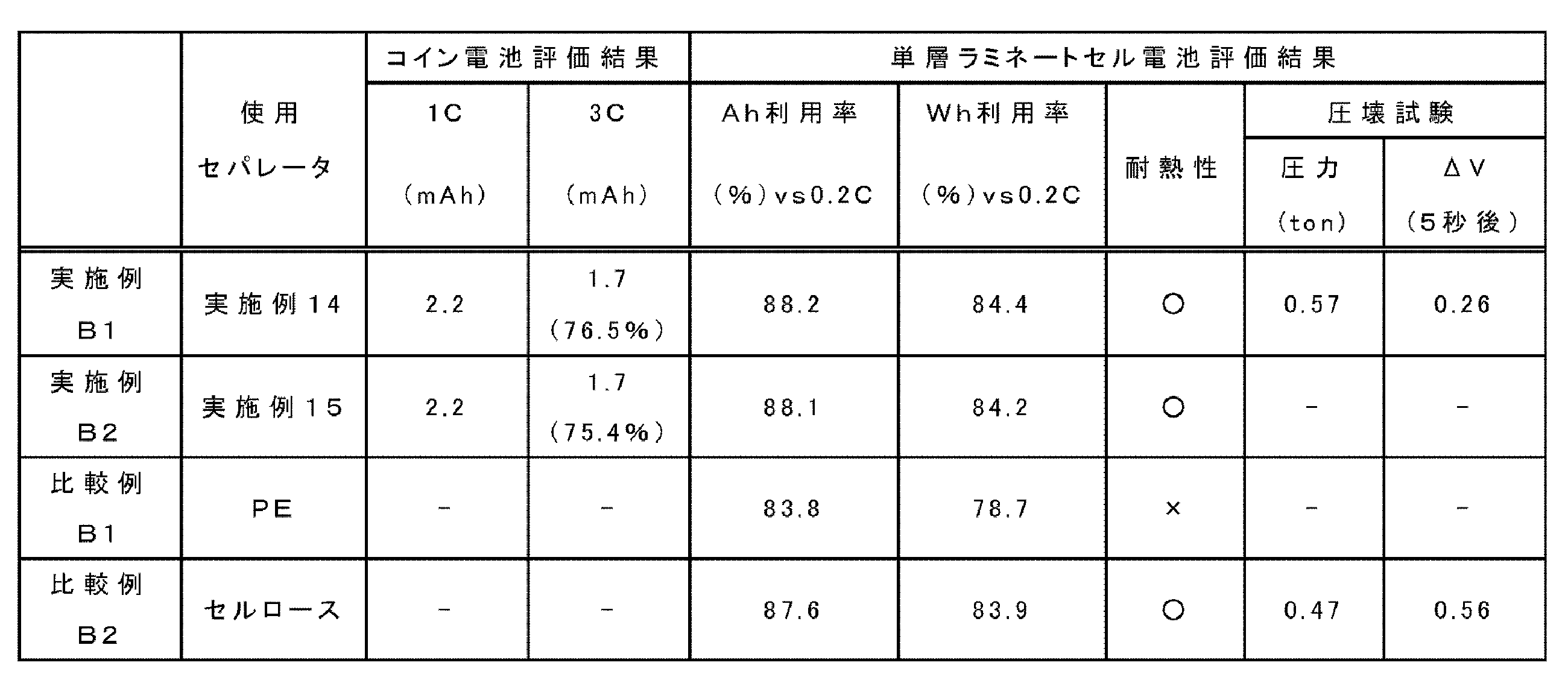
- Charging / discharging characteristics were as follows. Each of the evaluation coin batteries was charged in a thermostat at a current density of 2.2 mAh (1 C) up to 4.1 V (CC-CV operation), and then discharged to 2.5 V. Up to 2.2 mAh (1 C) and 3 C current density (CC operation). Table 3 shows the results. The values in Table 3 () are capacity retention rates (%) when the 1 C capacity is 100% of the capacitance at rate 3 C.
- the electrode a nickel-cobalt-manganese ternary positive electrode and an artificial graphite negative electrode were used, and the negative electrode side was arranged so that the layer-side surface formed with the first varnish was in contact with the negative electrode side. .
- a single-layer laminated cell battery was obtained in the same manner as described above. This is designated as Comparative Examples B1 and B2.
- the average pore diameter of the PE separator used was 80 nm, the film thickness was 20 ⁇ m, the air permeability was 270 seconds, and the porosity was 42%.
- the average pore diameter of the cellulose separator was 3000 nm, the film thickness was 25 ⁇ m, and the air permeability was For 135 seconds, the porosity was 70%.
- Heat resistance evaluation was performed according to the following criteria using a soldering iron of about 250 ° C. ⁇ : Even if the tip of the soldering iron was applied to the center of the film, it was not broken, but it was not broken. ⁇ : When the tip of the soldering iron was applied to the center of the film, it penetrated.
- FIG. 9 to 11 are photographs of the surface of the negative electrode taken out from the batteries of Example B1 and Comparative Examples B1 and B2 after the completion of the above charge / discharge characteristic evaluation test.
- white bright spots based on the generation of lithium dendrite were observed.
- the bright spots on the surface of the negative electrode are few, and it can be seen that the generation of lithium dendrite due to charge and discharge is effectively suppressed.
- the bright spot of the negative electrode surface taken out from Comparative Example B1 or B2 is large and numerous. That is, it can be confirmed that in the comparative example using a commercially available polyethylene (PE) -based or cellulose-based separator, generation of lithium dendrite occurs more frequently than when the separator of the present invention is used.
- PE polyethylene
- the amount of lithium dendrite generated on the negative electrode surface can be suppressed, and the capacity retention rate at low temperature is good. It is suggested that the electric field applied to can be made uniform.
- Varnish (5) was prepared by mixing and stirring 20 g of polyamideimide, 80 g of silica (1) as fine particles, 0.4 g of dispersant, and organic solvent (2).
- the mass ratio of polyamideimide and silica (1) in the varnish (5) is 20:80, and the volume ratio is approximately 28:72.
- the varnish (5) was formed on a PET film using an applicator. Prebaked at 100 ° C. for 5 minutes to produce an unfired composite film having a thickness of about 28 ⁇ m.
- the green composite film was peeled from the substrate and dried to obtain a green composite film (5), that is, a polyamideimide-fine particle composite film (1).
- the solvent was removed from the film.
- the baking process of the unbaked composite film was not performed.
- the Gurley air permeability is improved by chemical etching as in the case of the porous polyimide film, and the degree of communication between the front and back surfaces of the porous polyamideimide film is improved. Improved. From the relationship between permeation time and change in film thickness, the improvement in air permeability by chemical etching treatment is not only due to the reduction in film thickness, but mainly due to the increase in aperture ratio due to the opening of the surface and communication holes. Can be considered.
Landscapes
- Chemical & Material Sciences (AREA)
- Engineering & Computer Science (AREA)
- Chemical Kinetics & Catalysis (AREA)
- Materials Engineering (AREA)
- Manufacturing & Machinery (AREA)
- General Chemical & Material Sciences (AREA)
- Electrochemistry (AREA)
- Organic Chemistry (AREA)
- Polymers & Plastics (AREA)
- Medicinal Chemistry (AREA)
- Health & Medical Sciences (AREA)
- Inorganic Chemistry (AREA)
- Manufacture Of Porous Articles, And Recovery And Treatment Of Waste Products (AREA)
- Compositions Of Macromolecular Compounds (AREA)
- Cell Separators (AREA)
- Separation Using Semi-Permeable Membranes (AREA)
- Macromolecular Compounds Obtained By Forming Nitrogen-Containing Linkages In General (AREA)
Abstract
Description
ワニス製造は、予め微粒子が分散した有機溶剤とポリアミド酸、ポリイミド又はポリアミドイミドを任意の比率で混合するか、微粒子を予め分散した有機溶剤中でテトラカルボン酸二無水物及びジアミンを重合してポリアミド酸とするか、更にイミド化してポリイミドとすることで製造でき、最終的に、その粘度を300~1500cPとすることが好ましく、400~700cPの範囲がより好ましい。ワニスの粘度がこの範囲内であれば、均一に成膜をすることが可能である。
本発明で用いられる微粒子の材質は、ワニスに使用する有機溶剤に不溶で、成膜後選択的に除去可能なものなら、特に限定されること無く使用することができる。例えば、無機材料としては、シリカ(二酸化珪素)、酸化チタン、アルミナ(Al2O3)等の金属酸化物、有機材料としては、高分子量オレフィン(ポリプロピレン,ポリエチレン等)、ポリスチレン、アクリル系樹脂(メタクリル酸メチル、メタクリル酸イソブチル、ポリメチルメタクリレート(PMMA)等)、エポキシ樹脂、セルロース、ポリビニルアルコール、ポリビニルブチラール、ポリエステル、ポリエーテル等の有機高分子微粒子(樹脂微粒子)が挙げられる。
本発明に用いるポリアミド酸は、任意のテトラカルボン酸二無水物とジアミンを重合して得られるものが、特に限定されることなく使用できる。テトラカルボン酸二無水物及びジアミンの使用量は特に限定されないが、テトラカルボン酸二無水物1モルに対して、ジアミンを0.50~1.50モル用いるのが好ましく、0.60~1.30モル用いるのがより好ましく、0.70~1.20モル用いるのが特に好ましい。
本発明に用いるポリイミドは、本発明に係るワニスに使用する有機溶剤に溶解可能な可溶性ポリイミドなら、その構造や分子量に限定されることなく、公知のものが使用できる。ポリイミドについて、側鎖にカルボキシ基等の縮合可能な官能基又は焼成時に架橋反応等を促進させる官能基を有していてもよい。

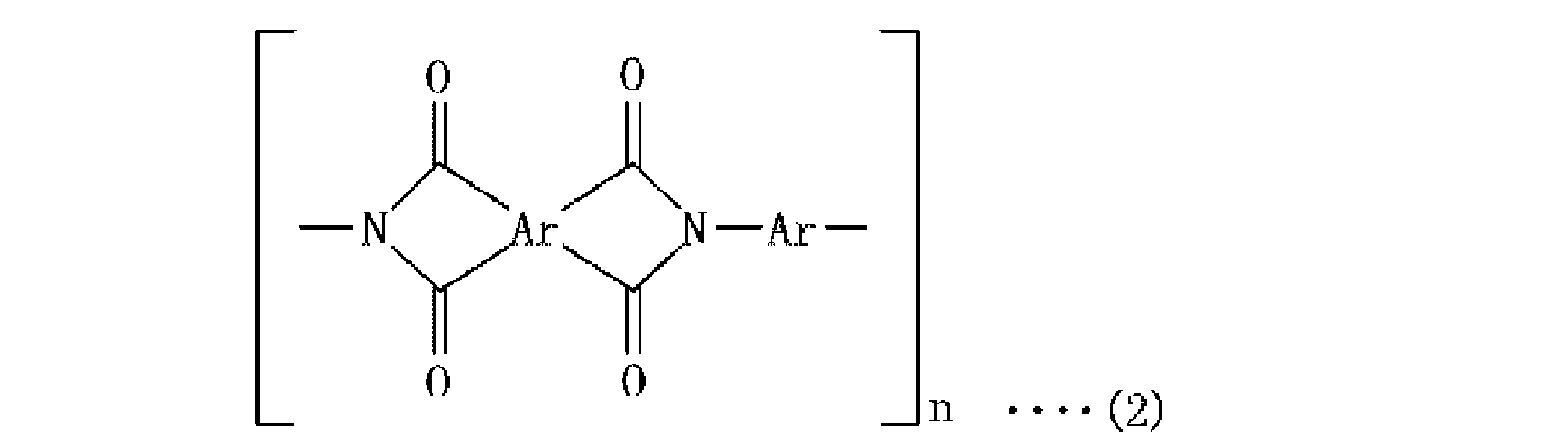
本発明に用いるポリアミドイミドは、本発明に係るワニスに使用する有機溶剤に溶解可能な可溶性ポリアミドイミドなら、その構造や分子量に限定されることなく、公知のものが使用できる。ポリアミドイミドについて、側鎖にカルボキシ基等の縮合可能な官能基又は焼成時に架橋反応等を促進させる官能基を有していてもよい。
ワニスに用いられる有機溶剤としては、ポリアミド酸及び/又はポリイミドからなる樹脂を溶解することができ、微粒子を溶解しないものであれば、特に限定されず、テトラカルボン酸二無水物とジアミンとの反応に用いる溶剤として例示したものが挙げられる。溶剤は、単独で用いてもよく、2種以上を組み合わせて用いてもよい。
ポリアミド酸又はポリイミド系樹脂と微粒子とを含有する未焼成複合膜の成膜は、基板上へ上記のワニスを塗布し、常圧又は真空下で50~100℃(好ましくは0~50℃)、より好ましくは常圧下60~95℃(更に好ましくは65~90℃)で乾燥して行う。なお、基板上には必要に応じて離型層を設けてもよい。
上記乾燥後の未焼成複合膜(又は2層状の未焼成複合膜、以下同様)に加熱による後処理(焼成)を行ってポリイミド系樹脂と微粒子とからなる複合膜(ポリイミド系樹脂-微粒子複合膜)とすることができる。ワニスにポリアミド酸を含む場合、焼成工程においてはイミド化を完結させることが好ましい。なお、焼成工程は任意の工程である。特にワニスにポリイミド又はポリアミドイミドが用いられる場合、焼成工程は行われなくてもよい。
ポリイミド系樹脂-微粒子複合膜から、微粒子を適切な方法を選択して除去することにより、微細孔を有する多孔質ポリイミド系樹脂膜を再現性よく製造することができる。例えば、微粒子として、シリカを採用した場合、ポリイミド系樹脂-微粒子複合膜を低濃度のフッ化水素水(HF)等によりシリカを溶解除去することで、多孔質とすることが可能である。また、微粒子が樹脂微粒子の場合は、上述のような樹脂微粒子の熱分解温度以上で、ポリイミド系樹脂の熱分解温度未満の温度に加熱し、樹脂微粒子を分解させてこれを取り除くことができる。
本発明の多孔質ポリイミド系樹脂膜の製造方法は、微粒子除去工程前に、ポリイミド系樹脂-微粒子複合膜のポリイミド系樹脂部分の少なくとも一部を除去するか、又は、微粒子除去工程後に多孔質ポリイミド系樹脂膜の少なくとも一部を除去するポリイミド系樹脂除去工程を有する。
上記本発明の製造方法で製造された多孔質ポリイミド系樹脂膜は、その開孔率がより一層高まるため、例えば、リチウムイオン電池のセパレーターとして使用すると電池の内部を小さくできるため好ましい。
本発明の多孔質ポリイミド系樹脂膜は、ニッケルカドミウム、ニッケル水素電池、リチウムイオン二次電池、リチウム金属二次電池等の二次電池用セパレータとして使用することが可能であるが、リチウムイオン二次電池用多孔質セパレータとして使用することが特に好ましい。更に、本発明の製造方法で作製した多孔質ポリイミド系樹脂膜は、二次電池用のセパレータのほか、燃料電池電解質膜、ガス又は液体の分離用膜、低誘電率材料として使用することも可能である。
本発明の第四の態様の二次電池は、負極と正極との間に、電解液及び第三の態様のセパレータが配置されることを特徴とする。
・テトラカルボン酸二無水物:ピロメリット酸二無水物
・ジアミン:4,4’-ジアミノジフェニルエーテル
・ポリアミド酸:ピロメリット酸二無水物と4,4’-ジアミノジフェニルエーテルとの反応物
・ポリアミドイミド:重合成分として無水トリメリット酸及びo-トリジンジイソシアネートを含むポリアミド(Mw:約3万)。
・有機溶剤(1):N,N-ジメチルアセトアミド:ガンマブチロラクトン(質量比90:10)の混合溶剤
・有機溶剤(2):N-メチル-2-ピロリドン:N,N-ジメチルアセトアミド(質量比70:30)の混合溶剤
・分散剤:ポリオキシエチレン二級アルキルエーテル系分散剤
・微粒子 :シリカ(1):平均粒径700nmのシリカ
シリカ(2):平均粒径200nmのシリカ
シリカ(3):平均粒径300nmのシリカ
ポリアミド酸13.25gと有機溶剤(1)30gとを混合しポリアミド酸溶液を得た。得られたポリアミド酸溶液に、微粒子としてシリカ(2)を、75g添加し撹拌して第一のワニスを調製した。なお、前記第一のワニスにおけるポリアミド酸とシリカ(2)との体積比は22:78(質量比は15:85)である。
ポリアミド酸13.25gと有機溶剤(1)30gとを混合しポリアミド酸溶液を得た。得られたポリアミド酸溶液に、微粒子としてシリカ(1)を、53g添加し撹拌して第二のワニスを調製した。なお、前記第二のワニスにおけるポリアミド酸とシリカ(1)との体積比は28:72(質量比は20:80)である。
上記の第二のワニスを、ガラス板にアプリケーターを用い成膜した。70℃で5分間プリベークして、膜厚25μmの未焼成複合膜を製造した。基材から未焼成複合膜を剥離乾燥して未焼成複合膜(1)を得た。
上記未焼成複合膜(1)を320℃で15分間加熱処理(ポストべーク)を施し、イミド化を完結させポリイミド-微粒子複合膜(1)を得た。
上記で得たポリイミド-微粒子複合膜(1)を、10%HF溶液中に10分間浸漬することで、膜中に含まれる微粒子を除去した後水洗及び乾燥を行い、多孔質ポリイミド膜(1)を得た。
上記の第一のワニスを、ガラス板にアプリケーターを用いて成膜した後、70℃1分間でベーク処理をし、膜厚約2μmの第一未焼成複合膜を得た。続いて、前記第一未焼成複合膜上に、第二のワニスを用いて第二未焼成複合膜を成膜した後、70℃で5分間プリベークして、全体の膜厚が約25μmの2層状の未焼成複合膜(2)を得た。
上記未焼成複合膜(2)を320℃で15分間加熱処理(ポストべーク)を施し、イミド化を完結させポリイミド-微粒子複合膜(2)を得た。
上記で得たポリイミド-微粒子複合膜(2)を、10%HF溶液中に10分間浸漬することで、膜中に含まれる微粒子を除去した後水洗及び乾燥を行い、多孔質ポリイミド膜(2)を得た。
上記で得た多孔質ポリイミド膜(2)について、テトラメチルアンモニウムヒドロキシド(TMAH)水溶液又はNaOH溶液を用いて下記表1の要領でケミカルエッチングの条件変更による比較を行った。
TMAHの2.38質量%水溶液(表1中、TMAHと記載)、又は、NaOHをメタノール50質量%水溶液で1.04%となるように希釈(表1中、NaOHと記載)して、アルカリ性のエッチング液を作成した。このエッチング液で、多孔質ポリイミド膜を表1に示す時間浸漬してポリイミドの一部を除去した。図7に、表1に示す条件で処理した後の多孔質ポリイミド膜の表面状態をSEMにて観察した結果を示す。
[ガーレー透気度]
上記実施例1~8の結果のうち、多孔質ポリイミド膜の一部が取り除かれた際の表面の孔の形状変化が良好だったNaOH含エッチング液を用い、上記で得た多孔質ポリイミド膜(1)(2)に対して、下記表1の要領でケミカルエッチングを行ったうえで、厚さ約25μmのサンプルを、5cm角に切り出した。ガーレー式デンソメーター(東洋精機製)を用いて、JIS P 8117に準じて、100mlの空気が上記サンプルを通過する時間を測定した。その結果を表1に併記する。なお、ケミカルエッチング処理前と処理後の膜厚を接触触針計により測定した結果についても、表1中にそれぞれ処理前膜厚と処理後膜厚として併記する。

上記多孔質ポリイミド膜(2)を得た際の[ワニスの調製]~[多孔質ポリイミド膜の形成]と同様にして多孔質ポリイミド膜を作成した。HF処理後、水洗した多孔質ポリイミド膜を濡れた状態のままポリエチレンテレフタレート(PET)フィルム上に載置してベークした。続いて、乾燥した多孔質ポリイミド膜をPETフィルムから引き剥がすと、多孔質ポリイミド膜がその表面層でPETフィルムに静電吸着しているために、その表面層のみがPETフィルム上に残される。なお、PETフィルムから引き剥がした面は第一のワニスにより形成された膜の方(リチウムイオン電池のセパレーターとして使用する場合負極面側となる方)である。
[ワニスの調製-3]
撹拌機、撹拌羽根、還流冷却機、窒素ガス導入管を備えたセパラブルフラスコに、テトラカルボン酸二無水物6.5gと、ジアミン6.7gと、有機溶剤(1)30gとを投入した。窒素ガス導入管よりフラスコ内に窒素を導入し、フラスコ内を窒素雰囲気とした。次いで、フラスコの内容物を撹拌しながら、50℃で20時間、テトラカルボン酸二無水物と、ジアミンとを反応させて、ポリアミド酸溶液を得た。得られたポリアミド酸溶液に、平均粒径が300nmのシリカ(3)を、75g添加し撹拌して、ポリアミド酸と微粒子との体積比を22:78(質量比は15:85)とした第一のワニスを調製した。
得られたポリアミド酸溶液に、平均粒径が700nmのシリカ(1)を53g添加するほかは、ワニスの調製-3と同様にして体積比を28:72(質量比は20:80)とした第二のワニスを調製した。
上記の第一のワニスを、ガラス板にアプリケーターを用いて成膜した後、70℃1分間でベーク処理をし、膜厚約1μmの第一未焼成複合膜を得た。続いて、第二のワニスを、前記第一未焼成複合膜にアプリケーターを用いて第二未焼成複合膜を成膜した後、70℃で5分間プリベークして、全体の膜厚が約20μmの2層状の未焼成複合膜(2)を得た。
上記ポリイミド-微粒子複合膜を、10%HF溶液中に10分間浸漬することで、膜中に含まれる微粒子を除去した。
TMAHの2.38質量%水溶液をメタノール50質量%水溶液で1.04%となるように希釈して、アルカリ性のエッチング液を作成した。このエッチング液に、多孔質ポリイミド膜を浸漬してポリイミド表面の一部を除去した。得られた多孔質ポリイミド膜の透気度は63秒であった。
ワニスの調製の際に、シリカ100重量部に対して10重量部の分散剤を使用したほかは、実施例14と同様にして多孔質ポリイミド膜を形成した。得られた多孔質ポリイミド膜の透気度は60秒であった。
多孔質ポリイミド膜の強度の評価として、多孔質ポリイミド膜の引張強度を測定した。
上記実施例14、15の多孔質ポリイミド膜のそれぞれについて、1cm×5cmの大きさに切り出して短冊状のサンプルを得た。このサンプルの破断時の応力(MPa)を、RTC-1210A TENSILON(ORIENTEC社製)を用いて評価した。

直径20mmのステンレス製コイン外装容器に、炭素負極電極、直径14mmの円形に切断した上記実施例14、15のセパレータ、直径14mmの円形に切断した金属リチウム、更にスペーサとして直径14mmの円形に切断した厚さ200μmの銅箔をこの順番に重ね合わせ、電解液(1mol・dm-3のLiPF6:エチレンカーボネート/ジエチルカーボネート=1/1混合溶液(体積比))を溢れない程度に数滴垂らし、ポリプロピレン製のパッキンを介して、ステンレス製のキャップを被せ、コイン電池作製用のかしめ器で密封してセパレータ評価用電池を作製した。製造に際して、第一のワニスを使用して製造した層側表面を負極に接するようにして、セパレータを使用した。この電池を、実施例B1及びB2とする。
充放電特性は、上記各評価用コイン電池を、恒温槽内で、充電は4.1Vまで2.2mAh(1C)の電流密度にて行った(CC-CV操作)後、放電を2.5Vまで2.2mAh(1C)、3Cの電流密度にて行った(CC操作)。表3にその結果を示す。表3()内の値は、レート3Cにおける静電容量の、1C容量を100%としたとき容量維持率(%)である。
アルミラミネート外装に20mm×20mmの正極、20mm×20mmの上記実施例のセパレータを順に入れ、電解液(溶媒:エチレンカーボネート:エチルメチルカーボネート=3:7、電解質塩:LiPF6 1mol/l)を添加した。更に、20mm×20mmの負極を入れて電池ケースを密閉し、実施例B1及びB2のリチウムイオン二次電池を得た。ここで、電極としては、ニッケル・コバルト・マンガン三元系の正極と、人造黒鉛系の負極を使用し、負極側に、第一のワニスで成膜された層側表面が接するように配置した。
作製したリチウムイオン二次電池を用い、充放電測定装置でリチウム吸蔵による電位変化を測定した。温度25℃、充電速度0.2Cで4.2Vになるまで充電し、10分間休止したのち、放電速度2Cで電圧範囲2.7Vまで放電した。放電後は、10分間休止した。その際の、電池のAh利用率及びWh利用率(エネルギー維持率)を評価した。その結果を表3に示す。
各例の電池に使用するセパレータについて、約250℃のはんだごてを用いて以下の基準により耐熱性評価を行った。
○: はんだごての先端をフィルムの中央におしつけてもあとはつくが破れなかった
×: はんだごての先端をフィルムの中央におしつけると突き抜けた
圧壊試験としては、単層ラミネートセル電池を電圧4.2Vで充電を行った後、電池を寝かせた状態で長さ方向に対し垂直方向に直径15.8mmの丸棒で圧縮し、電圧が降下した時点で電池の内部短絡が生じたと判断し、その圧力で評価した。また、電圧が降下した時点から5秒後における電圧の降下量をΔV(V)とした。上記圧力は高い値を示すほど好ましく、電圧の降下量は低いほど好ましい。
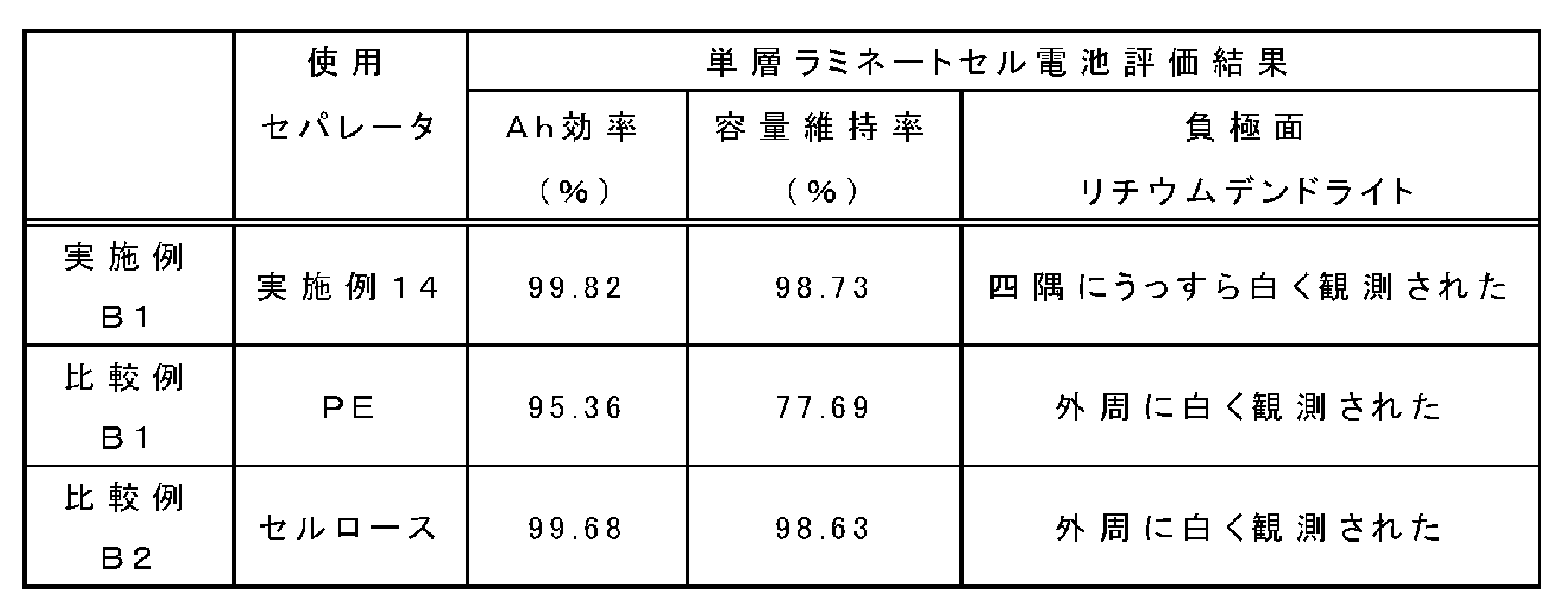
実施例B1、比較例B1、B2で作製したリチウムイオン二次電池を用い、充放電測定装置でリチウム吸蔵による電位変化を測定した。温度0℃、充電速度1Cで、充電CCCV:4.2V、CV:1時間、放電:2.7Vとして、5サイクル目のAh効率と容量維持率(1サイクル目の放電容量に対する割合)を求めた。その結果を、表4に示す。
上記充放電特性評価試験終了後の電池から、負極を取り出して、その表面を観察した。表4に、負極面上のデンドライトの発生状況を示す。また、実施例B1、比較例B1及び比較例B2の負極面表面を、光学顕微鏡により500倍に拡大して観察した。その像を図9~11に示す。
[ワニスの調製-5]
ポリアミドイミド20g、微粒子としてシリカ(1)80g、分散剤0.4g、及び有機溶剤(2)とを混合・撹拌してワニス(5)を調製した。なお、当該ワニス(5)におけるポリアミドイミドとシリカ(1)との質量比は20:80であり、体積比はおよそ28:72である。
上記のワニス(5)を、PETフィルム上にアプリケーターを用い成膜した。100℃で5分間プリベークして、膜厚約28μmの未焼成複合膜を製造した。基材から未焼成複合膜を剥離乾燥して未焼成複合膜(5)、すなわちポリアミドイミド-微粒子複合膜(1)を得た。未焼成複合膜(5)(ポリアミドイミド-微粒子複合膜(1))について、膜中から溶媒は除去されていた。なお、未焼成複合膜の焼成工程は行わなかった。
上記で得たポリアミドイミド-微粒子複合膜(1)を、10%HF溶液中に10分間浸漬することで、膜中に含まれる微粒子を除去した後水洗及び乾燥を行い、多孔質ポリアミドイミド膜(1)を得た。
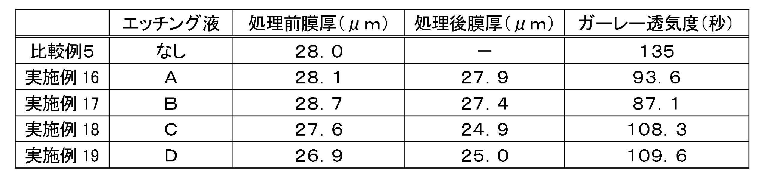
上記で得た多孔質ポリアミドイミド膜(1)について、下記のNaOH溶液を用いて下記表5の要領でケミカルエッチングの条件変更による比較を行った。
・ケミカルエッチング液A:NaOHを30質量%エタノール水溶液(H2O:EtOH=70:30)で1.0質量%となるように希釈
・ケミカルエッチング液B:NaOHを30質量%エタノール水溶液(H2O:EtOH=70:30)で1.5質量%となるように希釈
・ケミカルエッチング液C:NaOHを30質量%イソプロパノール水溶液(H2O:IPOH=70:30)で1.0質量%となるように希釈
・ケミカルエッチング液D:NaOHを30質量%イソプロパノール水溶液(H2O:IPOH=70:30)で1.5質量%となるように希釈
上記エッチング液A~Dで、多孔質ポリアミドイミド膜を2分間浸漬して(室温)ポリアミドイミドの一部を除去した。ケミカルエッチング前後の膜厚と、ケミカルエッチング後のガーレー透気度の結果(ただし、比較例5はケミカルエッチング前のガーレー透気度)について、表5に併記する。
2 ポリイミド系樹脂部分
3 空孔
4 多孔質ポリイミド系樹脂膜
Claims (6)
- ポリイミド系樹脂-微粒子複合膜から微粒子を取り除いて多孔質ポリイミド系樹脂膜とする微粒子除去工程を有する多孔質ポリイミド系樹脂膜の製造方法であって、
前記微粒子除去工程前に、前記ポリイミド系樹脂-微粒子複合膜のポリイミド系樹脂部分の少なくとも一部を除去するか、又は、前記微粒子除去工程後に、前記多孔質ポリイミド系樹脂膜の少なくとも一部を除去するポリイミド系樹脂除去工程を有する、多孔質ポリイミド系樹脂膜の製造方法。 - 前記ポリイミド系樹脂除去工程後の多孔質ポリイミド系樹脂膜の、厚さを25μmとし、空気の通過量を100mlとした場合におけるガーレー透気度(JIS P 8117)が120秒以内である、請求項1に記載の多孔質ポリイミド系樹脂膜の製造方法。
- 前記ポリイミド系樹脂除去工程が、ケミカルエッチング法により行われる、請求項1又は2に記載の多孔質ポリイミド系樹脂膜の製造方法。
- 請求項1~3のいずれか1項に記載の方法で製造される多孔質ポリイミド系樹脂膜。
- 請求項4に記載の多孔質ポリイミド系樹脂膜からなるセパレータ。
- 負極と正極との間に、電解液及び請求項5に記載のセパレータが配置される二次電池。
Priority Applications (5)
| Application Number | Priority Date | Filing Date | Title |
|---|---|---|---|
| JP2015530925A JP6058142B2 (ja) | 2013-08-08 | 2014-08-06 | 多孔質ポリイミド系樹脂膜の製造方法、多孔質ポリイミド系樹脂膜、及びそれを用いたセパレータ |
| CN201480044288.0A CN105452356B (zh) | 2013-08-08 | 2014-08-06 | 多孔聚酰亚胺系树脂膜的制造方法、多孔聚酰亚胺系树脂膜、以及使用了它的间隔件 |
| EP14835087.9A EP3029093B1 (en) | 2013-08-08 | 2014-08-06 | Production method for porous polyimide resin film, porous polyimide resin film, and separator employing same |
| KR1020167005043A KR101690916B1 (ko) | 2013-08-08 | 2014-08-06 | 다공질 폴리이미드계 수지막의 제조 방법, 다공질 폴리이미드계 수지막 및 그것을 사용한 세퍼레이터 |
| US14/909,716 US9683087B2 (en) | 2013-08-08 | 2014-08-06 | Production method for porous polyimide resin film, porous polyimide resin film, and separator employing same |
Applications Claiming Priority (4)
| Application Number | Priority Date | Filing Date | Title |
|---|---|---|---|
| JP2013-165407 | 2013-08-08 | ||
| JP2013165407 | 2013-08-08 | ||
| JP2014073987 | 2014-03-31 | ||
| JP2014-073987 | 2014-03-31 |
Publications (1)
| Publication Number | Publication Date |
|---|---|
| WO2015020101A1 true WO2015020101A1 (ja) | 2015-02-12 |
Family
ID=52461432
Family Applications (1)
| Application Number | Title | Priority Date | Filing Date |
|---|---|---|---|
| PCT/JP2014/070769 Ceased WO2015020101A1 (ja) | 2013-08-08 | 2014-08-06 | 多孔質ポリイミド系樹脂膜の製造方法、多孔質ポリイミド系樹脂膜、及びそれを用いたセパレータ |
Country Status (7)
| Country | Link |
|---|---|
| US (1) | US9683087B2 (ja) |
| EP (1) | EP3029093B1 (ja) |
| JP (1) | JP6058142B2 (ja) |
| KR (1) | KR101690916B1 (ja) |
| CN (1) | CN105452356B (ja) |
| TW (1) | TWI628213B (ja) |
| WO (1) | WO2015020101A1 (ja) |
Cited By (20)
| Publication number | Priority date | Publication date | Assignee | Title |
|---|---|---|---|---|
| CN104742461A (zh) * | 2015-04-16 | 2015-07-01 | 达迈科技股份有限公司 | 低光泽度的双层聚酰亚胺膜及其制造方法 |
| JP2016056225A (ja) * | 2014-09-05 | 2016-04-21 | 東京応化工業株式会社 | 多孔質膜製造用ワニス、それを用いた多孔質膜の製造方法及びポリアミドイミド多孔質膜 |
| WO2016125832A1 (ja) * | 2015-02-06 | 2016-08-11 | 東京応化工業株式会社 | ポリイミド及び/又はポリアミドイミド多孔質体並びにその製造方法、分離及び/又は吸着を行う方法、分離材、吸着材、フィルターメディア、積層体、並びに、フィルターデバイス |
| JP2016183333A (ja) * | 2015-03-26 | 2016-10-20 | 富士ゼロックス株式会社 | 樹脂粒子分散ポリイミド前駆体溶液の製造方法、樹脂粒子分散ポリイミド前駆体溶液、樹脂粒子含有ポリイミドフィルム、多孔質ポリイミドフィルムの製造方法、及び多孔質ポリイミドフィルム |
| JP2016183273A (ja) * | 2015-03-26 | 2016-10-20 | 富士ゼロックス株式会社 | 多孔質ポリイミドフィルム |
| JP2016183332A (ja) * | 2015-03-26 | 2016-10-20 | 富士ゼロックス株式会社 | 多孔質ポリイミドフィルムの製造方法、及び多孔質ポリイミドフィルム |
| JP2016192324A (ja) * | 2015-03-31 | 2016-11-10 | 東京応化工業株式会社 | 多孔質ポリアミドイミド膜形成用ワニス、多孔質ポリアミドイミド膜並びにそれを用いたセパレータ及び二次電池 |
| WO2017014147A1 (ja) * | 2015-07-23 | 2017-01-26 | 東京応化工業株式会社 | 多孔質膜、ロール体、リチウムイオン二次電池用セパレータ、及び多孔質膜の製造方法 |
| WO2017038897A1 (ja) * | 2015-09-04 | 2017-03-09 | 東京応化工業株式会社 | 多孔質膜の製造方法 |
| JP2017064712A (ja) * | 2015-09-30 | 2017-04-06 | 東京応化工業株式会社 | 濾過フィルター及び濾過方法、並びにリソグラフィー用薬液精製品の製造方法 |
| JP2017064711A (ja) * | 2015-09-30 | 2017-04-06 | 東京応化工業株式会社 | 濾過フィルター及び濾過方法、並びにリソグラフィー用薬液精製品の製造方法 |
| WO2017082088A1 (ja) * | 2015-11-10 | 2017-05-18 | 東京応化工業株式会社 | 液体を被精製物とする精製方法、ケイ素化合物含有液を被精製物とする精製方法、シリル化剤薬液、膜形成用材料又は拡散剤組成物の製造方法、フィルターメディア、及び、フィルターデバイス |
| JP2017127992A (ja) * | 2016-01-18 | 2017-07-27 | 東京応化工業株式会社 | 多孔質膜 |
| EP3159057A3 (en) * | 2015-09-30 | 2017-08-09 | Tokyo Ohka Kogyo Co., Ltd. | Filtration filter, filtration method, production method of purified liquid chemical product for lithography, and method of forming resist pattern |
| JP2018097915A (ja) * | 2016-12-08 | 2018-06-21 | 公立大学法人首都大学東京 | 3次元規則配列マクロポア構造を有するポリイミドセパレータ及びその製造方法 |
| JP2018138645A (ja) * | 2017-02-24 | 2018-09-06 | 富士ゼロックス株式会社 | ポリイミド前駆体溶液の製造方法、ポリイミド前駆体溶液、及び多孔質ポリイミドフィルムの製造方法 |
| JP2018138644A (ja) * | 2017-02-24 | 2018-09-06 | 富士ゼロックス株式会社 | ポリイミド前駆体溶液、及び多孔質ポリイミドフィルムの製造方法 |
| US10195794B2 (en) * | 2015-03-26 | 2019-02-05 | Fuji Xerox Co., Ltd. | Method for producing porous polyimide film, and porous polyimide film |
| JP2019131709A (ja) * | 2018-01-31 | 2019-08-08 | 富士ゼロックス株式会社 | 多孔質ポリイミド成形体及び多孔質ポリイミド成形体の製造方法 |
| KR20200016795A (ko) | 2018-08-07 | 2020-02-17 | 도쿄 오카 고교 가부시키가이샤 | 이미드계 수지막 제조 시스템, 이미드계 수지막 제조 방법, 및 세퍼레이터 |
Families Citing this family (12)
| Publication number | Priority date | Publication date | Assignee | Title |
|---|---|---|---|---|
| CN109608682A (zh) | 2013-04-22 | 2019-04-12 | 东京应化工业株式会社 | 多孔聚酰亚胺膜的制造方法、多孔聚酰亚胺膜和使用了该多孔聚酰亚胺膜的隔板 |
| TWI665024B (zh) * | 2014-06-20 | 2019-07-11 | 日商東京應化工業股份有限公司 | 塗佈裝置及多孔性之醯亞胺系樹脂膜製造系統 |
| TWI701292B (zh) * | 2014-06-20 | 2020-08-11 | 日商東京應化工業股份有限公司 | 醯亞胺系樹脂膜製造系統及醯亞胺系樹脂膜製造方法 |
| TWI673154B (zh) * | 2014-06-20 | 2019-10-01 | 日商東京應化工業股份有限公司 | 多孔性之醯亞胺系樹脂膜製造系統、分隔膜及多孔性之醯亞胺系樹脂膜製造方法 |
| JP6835848B2 (ja) * | 2016-08-03 | 2021-02-24 | 東京応化工業株式会社 | 液体の精製方法、及び多孔質膜の製造方法 |
| JP7024225B2 (ja) * | 2017-06-29 | 2022-02-24 | 富士フイルムビジネスイノベーション株式会社 | ポリイミド積層膜、及びポリイミド積層膜の製造方法 |
| WO2019093498A1 (ja) | 2017-11-10 | 2019-05-16 | 旭化成株式会社 | 蓄電デバイス用セパレータ、及び蓄電デバイス |
| JP7495788B2 (ja) * | 2018-12-26 | 2024-06-05 | 住友化学株式会社 | ポリイミド系樹脂の製造方法 |
| JP7419815B2 (ja) * | 2019-12-27 | 2024-01-23 | 富士フイルムビジネスイノベーション株式会社 | 多孔質ポリイミドフィルム、二次電池用セパレータ、及び二次電池 |
| CN114085406B (zh) * | 2021-11-03 | 2023-07-18 | 广州明美新能源股份有限公司 | 一种孔径可控的聚酰胺酰亚胺涂覆改性聚烯烃隔离膜及其制备方法与应用 |
| CN116875183B (zh) * | 2023-06-27 | 2024-05-31 | 苏州科丽尔化学有限公司 | 一种电池液冷板涂层及其制备方法 |
| CN120199972B (zh) * | 2025-05-19 | 2025-08-05 | 宁波博雅聚力新材料科技有限公司 | 一种聚酰亚胺微球改性的复合隔膜及其制备方法与应用 |
Citations (7)
| Publication number | Priority date | Publication date | Assignee | Title |
|---|---|---|---|---|
| JPH11144697A (ja) * | 1997-11-10 | 1999-05-28 | Japan Storage Battery Co Ltd | 非水電解質電池 |
| JP2004204119A (ja) * | 2002-12-26 | 2004-07-22 | Mitsubishi Paper Mills Ltd | 多孔質フィルム及びこれを用いた電気化学素子 |
| JP2010195899A (ja) * | 2009-02-24 | 2010-09-09 | Sumitomo Chemical Co Ltd | 多孔質フィルムの製造方法、多孔質フィルム、積層多孔質フィルムの製造方法、積層多孔質フィルムおよび電池用セパレータ |
| JP2010537387A (ja) | 2007-08-21 | 2010-12-02 | エイ 123 システムズ,インク. | 電気化学セル用セパレータおよびその製造方法 |
| JP2011111470A (ja) | 2009-11-24 | 2011-06-09 | Tokyo Metropolitan Univ | 多孔質ポリイミドおよびその製造方法 |
| JP2012107144A (ja) | 2010-11-18 | 2012-06-07 | Tokyo Metropolitan Univ | 多孔質ポリイミド膜の製造方法 |
| JP2013109842A (ja) * | 2011-11-17 | 2013-06-06 | Ibiden Co Ltd | リチウムイオン電池用セパレータの製造方法 |
Family Cites Families (5)
| Publication number | Priority date | Publication date | Assignee | Title |
|---|---|---|---|---|
| US6635381B2 (en) * | 2000-05-11 | 2003-10-21 | Wilson Greatbatch Ltd. | Electrochemical lithium ion secondary cell having a scalloped electrode assembly |
| JP5530178B2 (ja) * | 2007-03-19 | 2014-06-25 | イビデン株式会社 | 多孔性ポリイミド |
| JP2008231369A (ja) * | 2007-03-23 | 2008-10-02 | Yamaha Corp | 多孔板吸音体の製造方法 |
| JP2009177071A (ja) * | 2008-01-28 | 2009-08-06 | Raytech Kk | ポリイミドフィルム回路基板およびその製造方法 |
| CN102530843B (zh) * | 2012-01-20 | 2014-08-13 | 中国科学院上海技术物理研究所 | 一种疏松化聚酰亚胺红外吸收薄膜的制备方法 |
-
2014
- 2014-08-06 CN CN201480044288.0A patent/CN105452356B/zh active Active
- 2014-08-06 WO PCT/JP2014/070769 patent/WO2015020101A1/ja not_active Ceased
- 2014-08-06 JP JP2015530925A patent/JP6058142B2/ja active Active
- 2014-08-06 TW TW103127189A patent/TWI628213B/zh active
- 2014-08-06 EP EP14835087.9A patent/EP3029093B1/en active Active
- 2014-08-06 KR KR1020167005043A patent/KR101690916B1/ko active Active
- 2014-08-06 US US14/909,716 patent/US9683087B2/en active Active
Patent Citations (7)
| Publication number | Priority date | Publication date | Assignee | Title |
|---|---|---|---|---|
| JPH11144697A (ja) * | 1997-11-10 | 1999-05-28 | Japan Storage Battery Co Ltd | 非水電解質電池 |
| JP2004204119A (ja) * | 2002-12-26 | 2004-07-22 | Mitsubishi Paper Mills Ltd | 多孔質フィルム及びこれを用いた電気化学素子 |
| JP2010537387A (ja) | 2007-08-21 | 2010-12-02 | エイ 123 システムズ,インク. | 電気化学セル用セパレータおよびその製造方法 |
| JP2010195899A (ja) * | 2009-02-24 | 2010-09-09 | Sumitomo Chemical Co Ltd | 多孔質フィルムの製造方法、多孔質フィルム、積層多孔質フィルムの製造方法、積層多孔質フィルムおよび電池用セパレータ |
| JP2011111470A (ja) | 2009-11-24 | 2011-06-09 | Tokyo Metropolitan Univ | 多孔質ポリイミドおよびその製造方法 |
| JP2012107144A (ja) | 2010-11-18 | 2012-06-07 | Tokyo Metropolitan Univ | 多孔質ポリイミド膜の製造方法 |
| JP2013109842A (ja) * | 2011-11-17 | 2013-06-06 | Ibiden Co Ltd | リチウムイオン電池用セパレータの製造方法 |
Non-Patent Citations (1)
| Title |
|---|
| See also references of EP3029093A4 |
Cited By (34)
| Publication number | Priority date | Publication date | Assignee | Title |
|---|---|---|---|---|
| JP2016056225A (ja) * | 2014-09-05 | 2016-04-21 | 東京応化工業株式会社 | 多孔質膜製造用ワニス、それを用いた多孔質膜の製造方法及びポリアミドイミド多孔質膜 |
| JPWO2016125832A1 (ja) * | 2015-02-06 | 2017-12-07 | 東京応化工業株式会社 | ポリイミド及び/又はポリアミドイミド多孔質体並びにその製造方法、分離及び/又は吸着を行う方法、分離材、吸着材、フィルターメディア、積層体、並びに、フィルターデバイス |
| WO2016125832A1 (ja) * | 2015-02-06 | 2016-08-11 | 東京応化工業株式会社 | ポリイミド及び/又はポリアミドイミド多孔質体並びにその製造方法、分離及び/又は吸着を行う方法、分離材、吸着材、フィルターメディア、積層体、並びに、フィルターデバイス |
| US10576432B2 (en) | 2015-02-06 | 2020-03-03 | Tokyo Ohka Kogyo Co., Ltd. | Polyimide and/or polyamideimide porous body and method for manufacturing same, method for separation and/or adsorption, separation material, adsorption material, filter media, laminate, and filter device |
| JP2016183333A (ja) * | 2015-03-26 | 2016-10-20 | 富士ゼロックス株式会社 | 樹脂粒子分散ポリイミド前駆体溶液の製造方法、樹脂粒子分散ポリイミド前駆体溶液、樹脂粒子含有ポリイミドフィルム、多孔質ポリイミドフィルムの製造方法、及び多孔質ポリイミドフィルム |
| JP2016183273A (ja) * | 2015-03-26 | 2016-10-20 | 富士ゼロックス株式会社 | 多孔質ポリイミドフィルム |
| JP2016183332A (ja) * | 2015-03-26 | 2016-10-20 | 富士ゼロックス株式会社 | 多孔質ポリイミドフィルムの製造方法、及び多孔質ポリイミドフィルム |
| JP2020109189A (ja) * | 2015-03-26 | 2020-07-16 | 富士ゼロックス株式会社 | 樹脂粒子分散ポリイミド前駆体溶液の製造方法、樹脂粒子分散ポリイミド前駆体溶液、樹脂粒子含有ポリイミドフィルム、多孔質ポリイミドフィルムの製造方法、及び多孔質ポリイミドフィルム |
| US10195794B2 (en) * | 2015-03-26 | 2019-02-05 | Fuji Xerox Co., Ltd. | Method for producing porous polyimide film, and porous polyimide film |
| JP2016192324A (ja) * | 2015-03-31 | 2016-11-10 | 東京応化工業株式会社 | 多孔質ポリアミドイミド膜形成用ワニス、多孔質ポリアミドイミド膜並びにそれを用いたセパレータ及び二次電池 |
| CN104742461A (zh) * | 2015-04-16 | 2015-07-01 | 达迈科技股份有限公司 | 低光泽度的双层聚酰亚胺膜及其制造方法 |
| WO2017014147A1 (ja) * | 2015-07-23 | 2017-01-26 | 東京応化工業株式会社 | 多孔質膜、ロール体、リチウムイオン二次電池用セパレータ、及び多孔質膜の製造方法 |
| KR20180050349A (ko) * | 2015-09-04 | 2018-05-14 | 도쿄 오카 고교 가부시키가이샤 | 다공질막의 제조 방법 |
| WO2017038897A1 (ja) * | 2015-09-04 | 2017-03-09 | 東京応化工業株式会社 | 多孔質膜の製造方法 |
| CN113717428A (zh) * | 2015-09-04 | 2021-11-30 | 东京应化工业株式会社 | 多孔膜的制造方法 |
| US10865286B2 (en) | 2015-09-04 | 2020-12-15 | Tokyo Ohka Kogyo Co., Ltd. | Method for manufacturing porous membrane |
| KR102070150B1 (ko) * | 2015-09-04 | 2020-01-29 | 도쿄 오카 고교 가부시키가이샤 | 다공질막의 제조 방법 |
| JPWO2017038897A1 (ja) * | 2015-09-04 | 2018-08-30 | 東京応化工業株式会社 | 多孔質膜の製造方法 |
| JP2017064712A (ja) * | 2015-09-30 | 2017-04-06 | 東京応化工業株式会社 | 濾過フィルター及び濾過方法、並びにリソグラフィー用薬液精製品の製造方法 |
| JP2017064711A (ja) * | 2015-09-30 | 2017-04-06 | 東京応化工業株式会社 | 濾過フィルター及び濾過方法、並びにリソグラフィー用薬液精製品の製造方法 |
| US10429738B2 (en) | 2015-09-30 | 2019-10-01 | Tokyo Ohka Kogyo Co., Ltd. | Filtration filter, filtration method, production method of purified liquid chemical product for lithography, and method of forming resist pattern |
| JP7004859B2 (ja) | 2015-09-30 | 2022-02-04 | 東京応化工業株式会社 | 濾過フィルター及び濾過方法、並びにリソグラフィー用薬液精製品の製造方法 |
| EP3159057A3 (en) * | 2015-09-30 | 2017-08-09 | Tokyo Ohka Kogyo Co., Ltd. | Filtration filter, filtration method, production method of purified liquid chemical product for lithography, and method of forming resist pattern |
| JP2021074716A (ja) * | 2015-09-30 | 2021-05-20 | 東京応化工業株式会社 | 濾過フィルター及び濾過方法、並びにリソグラフィー用薬液精製品の製造方法 |
| US10525418B2 (en) | 2015-11-10 | 2020-01-07 | Tokyo Ohka Kogyo Co., Ltd. | Purification method for purifying liquid, purification method for purifying silicon compound-containing liquid, method for producing silylating agent liquid, film forming material or diffusing agent composition, filter medium and filter device |
| WO2017082088A1 (ja) * | 2015-11-10 | 2017-05-18 | 東京応化工業株式会社 | 液体を被精製物とする精製方法、ケイ素化合物含有液を被精製物とする精製方法、シリル化剤薬液、膜形成用材料又は拡散剤組成物の製造方法、フィルターメディア、及び、フィルターデバイス |
| JP2017087138A (ja) * | 2015-11-10 | 2017-05-25 | 東京応化工業株式会社 | 液体を被精製物とする精製方法、ケイ素化合物含有液を被精製物とする精製方法、シリル化剤薬液、膜形成用材料又は拡散剤組成物の製造方法、フィルターメディア、及び、フィルターデバイス |
| JP2017127992A (ja) * | 2016-01-18 | 2017-07-27 | 東京応化工業株式会社 | 多孔質膜 |
| JP2018097915A (ja) * | 2016-12-08 | 2018-06-21 | 公立大学法人首都大学東京 | 3次元規則配列マクロポア構造を有するポリイミドセパレータ及びその製造方法 |
| JP2018138645A (ja) * | 2017-02-24 | 2018-09-06 | 富士ゼロックス株式会社 | ポリイミド前駆体溶液の製造方法、ポリイミド前駆体溶液、及び多孔質ポリイミドフィルムの製造方法 |
| JP2018138644A (ja) * | 2017-02-24 | 2018-09-06 | 富士ゼロックス株式会社 | ポリイミド前駆体溶液、及び多孔質ポリイミドフィルムの製造方法 |
| JP2019131709A (ja) * | 2018-01-31 | 2019-08-08 | 富士ゼロックス株式会社 | 多孔質ポリイミド成形体及び多孔質ポリイミド成形体の製造方法 |
| JP7047415B2 (ja) | 2018-01-31 | 2022-04-05 | 富士フイルムビジネスイノベーション株式会社 | 多孔質ポリイミド成形体及び多孔質ポリイミド成形体の製造方法 |
| KR20200016795A (ko) | 2018-08-07 | 2020-02-17 | 도쿄 오카 고교 가부시키가이샤 | 이미드계 수지막 제조 시스템, 이미드계 수지막 제조 방법, 및 세퍼레이터 |
Also Published As
| Publication number | Publication date |
|---|---|
| CN105452356A (zh) | 2016-03-30 |
| TW201520250A (zh) | 2015-06-01 |
| EP3029093A1 (en) | 2016-06-08 |
| KR101690916B1 (ko) | 2016-12-28 |
| CN105452356B (zh) | 2018-02-09 |
| JPWO2015020101A1 (ja) | 2017-03-02 |
| TWI628213B (zh) | 2018-07-01 |
| US20160185932A1 (en) | 2016-06-30 |
| KR20160030320A (ko) | 2016-03-16 |
| JP6058142B2 (ja) | 2017-01-11 |
| EP3029093B1 (en) | 2018-11-14 |
| US9683087B2 (en) | 2017-06-20 |
| EP3029093A4 (en) | 2016-06-08 |
Similar Documents
| Publication | Publication Date | Title |
|---|---|---|
| JP6058142B2 (ja) | 多孔質ポリイミド系樹脂膜の製造方法、多孔質ポリイミド系樹脂膜、及びそれを用いたセパレータ | |
| JP5745195B2 (ja) | 多孔質ポリイミド膜の製造方法、多孔質ポリイミド膜、及びそれを用いたセパレータ | |
| JP6404426B2 (ja) | 二次電池用多孔質セパレータおよびそれを用いた二次電池 | |
| JP6596196B2 (ja) | 多孔質膜製造用ワニスの製造方法 | |
| JP7053145B2 (ja) | 多孔質ポリイミド膜製造用ワニス及びそれを用いた多孔質ポリイミド膜の製造方法 | |
| JP6681835B2 (ja) | 多孔質ポリイミド膜の製造方法 | |
| JP6441148B2 (ja) | 多孔質ポリアミドイミド膜形成用ワニス、多孔質ポリアミドイミド膜並びにそれを用いたセパレータ及び二次電池 | |
| JP6383243B2 (ja) | 多孔質膜、その製造方法、二次電池用多孔質セパレータ及び二次電池 | |
| JP7246182B2 (ja) | 二次電池、及び二次電池用多孔質セパレータ | |
| JP2016079310A (ja) | 多孔質膜製造用ワニス、それを用いた多孔質膜の製造方法、及び多孔質膜製造用空孔形成剤 |
Legal Events
| Date | Code | Title | Description |
|---|---|---|---|
| WWE | Wipo information: entry into national phase |
Ref document number: 201480044288.0 Country of ref document: CN |
|
| 121 | Ep: the epo has been informed by wipo that ep was designated in this application |
Ref document number: 14835087 Country of ref document: EP Kind code of ref document: A1 |
|
| ENP | Entry into the national phase |
Ref document number: 2015530925 Country of ref document: JP Kind code of ref document: A |
|
| WWE | Wipo information: entry into national phase |
Ref document number: 14909716 Country of ref document: US |
|
| NENP | Non-entry into the national phase |
Ref country code: DE |
|
| ENP | Entry into the national phase |
Ref document number: 20167005043 Country of ref document: KR Kind code of ref document: A |
|
| WWE | Wipo information: entry into national phase |
Ref document number: 2014835087 Country of ref document: EP |