WO2015022814A1 - 通信制御装置、通信制御方法、無線通信システム及び端末装置 - Google Patents
通信制御装置、通信制御方法、無線通信システム及び端末装置 Download PDFInfo
- Publication number
- WO2015022814A1 WO2015022814A1 PCT/JP2014/066746 JP2014066746W WO2015022814A1 WO 2015022814 A1 WO2015022814 A1 WO 2015022814A1 JP 2014066746 W JP2014066746 W JP 2014066746W WO 2015022814 A1 WO2015022814 A1 WO 2015022814A1
- Authority
- WO
- WIPO (PCT)
- Prior art keywords
- mode
- wireless communication
- base station
- unit
- small cell
- Prior art date
- Legal status (The legal status is an assumption and is not a legal conclusion. Google has not performed a legal analysis and makes no representation as to the accuracy of the status listed.)
- Ceased
Links
Images










Classifications
-
- H—ELECTRICITY
- H04—ELECTRIC COMMUNICATION TECHNIQUE
- H04W—WIRELESS COMMUNICATION NETWORKS
- H04W36/00—Hand-off or reselection arrangements
- H04W36/04—Reselecting a cell layer in multi-layered cells
-
- H—ELECTRICITY
- H04—ELECTRIC COMMUNICATION TECHNIQUE
- H04W—WIRELESS COMMUNICATION NETWORKS
- H04W16/00—Network planning, e.g. coverage or traffic planning tools; Network deployment, e.g. resource partitioning or cells structures
- H04W16/02—Resource partitioning among network components, e.g. reuse partitioning
- H04W16/06—Hybrid resource partitioning, e.g. channel borrowing
- H04W16/08—Load shedding arrangements
-
- H—ELECTRICITY
- H04—ELECTRIC COMMUNICATION TECHNIQUE
- H04W—WIRELESS COMMUNICATION NETWORKS
- H04W36/00—Hand-off or reselection arrangements
- H04W36/16—Performing reselection for specific purposes
- H04W36/165—Performing reselection for specific purposes for reducing network power consumption
-
- H—ELECTRICITY
- H04—ELECTRIC COMMUNICATION TECHNIQUE
- H04W—WIRELESS COMMUNICATION NETWORKS
- H04W52/00—Power management, e.g. Transmission Power Control [TPC] or power classes
- H04W52/02—Power saving arrangements
- H04W52/0203—Power saving arrangements in the radio access network or backbone network of wireless communication networks
- H04W52/0206—Power saving arrangements in the radio access network or backbone network of wireless communication networks in access points, e.g. base stations
-
- H—ELECTRICITY
- H04—ELECTRIC COMMUNICATION TECHNIQUE
- H04W—WIRELESS COMMUNICATION NETWORKS
- H04W52/00—Power management, e.g. Transmission Power Control [TPC] or power classes
- H04W52/04—Transmission power control [TPC]
- H04W52/30—Transmission power control [TPC] using constraints in the total amount of available transmission power
- H04W52/34—TPC management, i.e. sharing limited amount of power among users or channels or data types, e.g. cell loading
- H04W52/343—TPC management, i.e. sharing limited amount of power among users or channels or data types, e.g. cell loading taking into account loading or congestion level
-
- H—ELECTRICITY
- H04—ELECTRIC COMMUNICATION TECHNIQUE
- H04W—WIRELESS COMMUNICATION NETWORKS
- H04W88/00—Devices specially adapted for wireless communication networks, e.g. terminals, base stations or access point devices
-
- H—ELECTRICITY
- H04—ELECTRIC COMMUNICATION TECHNIQUE
- H04L—TRANSMISSION OF DIGITAL INFORMATION, e.g. TELEGRAPHIC COMMUNICATION
- H04L5/00—Arrangements affording multiple use of the transmission path
- H04L5/0001—Arrangements for dividing the transmission path
- H04L5/0003—Two-dimensional division
- H04L5/0005—Time-frequency
- H04L5/0007—Time-frequency the frequencies being orthogonal, e.g. OFDM(A) or DMT
- H04L5/001—Time-frequency the frequencies being orthogonal, e.g. OFDM(A) or DMT the frequencies being arranged in component carriers
-
- H—ELECTRICITY
- H04—ELECTRIC COMMUNICATION TECHNIQUE
- H04L—TRANSMISSION OF DIGITAL INFORMATION, e.g. TELEGRAPHIC COMMUNICATION
- H04L5/00—Arrangements affording multiple use of the transmission path
- H04L5/003—Arrangements for allocating sub-channels of the transmission path
- H04L5/0032—Distributed allocation, i.e. involving a plurality of allocating devices, each making partial allocation
- H04L5/0035—Resource allocation in a cooperative multipoint environment
-
- H—ELECTRICITY
- H04—ELECTRIC COMMUNICATION TECHNIQUE
- H04L—TRANSMISSION OF DIGITAL INFORMATION, e.g. TELEGRAPHIC COMMUNICATION
- H04L5/00—Arrangements affording multiple use of the transmission path
- H04L5/003—Arrangements for allocating sub-channels of the transmission path
- H04L5/0058—Allocation criteria
- H04L5/0064—Rate requirement of the data, e.g. scalable bandwidth, data priority
-
- H—ELECTRICITY
- H04—ELECTRIC COMMUNICATION TECHNIQUE
- H04L—TRANSMISSION OF DIGITAL INFORMATION, e.g. TELEGRAPHIC COMMUNICATION
- H04L5/00—Arrangements affording multiple use of the transmission path
- H04L5/0091—Signalling for the administration of the divided path, e.g. signalling of configuration information
- H04L5/0096—Indication of changes in allocation
- H04L5/0098—Signalling of the activation or deactivation of component carriers, subcarriers or frequency bands
-
- H—ELECTRICITY
- H04—ELECTRIC COMMUNICATION TECHNIQUE
- H04W—WIRELESS COMMUNICATION NETWORKS
- H04W16/00—Network planning, e.g. coverage or traffic planning tools; Network deployment, e.g. resource partitioning or cells structures
- H04W16/24—Cell structures
- H04W16/32—Hierarchical cell structures
-
- H—ELECTRICITY
- H04—ELECTRIC COMMUNICATION TECHNIQUE
- H04W—WIRELESS COMMUNICATION NETWORKS
- H04W52/00—Power management, e.g. Transmission Power Control [TPC] or power classes
- H04W52/04—Transmission power control [TPC]
- H04W52/30—Transmission power control [TPC] using constraints in the total amount of available transmission power
- H04W52/36—Transmission power control [TPC] using constraints in the total amount of available transmission power with a discrete range or set of values, e.g. step size, ramping or offsets
- H04W52/362—Aspects of the step size
-
- H—ELECTRICITY
- H04—ELECTRIC COMMUNICATION TECHNIQUE
- H04W—WIRELESS COMMUNICATION NETWORKS
- H04W84/00—Network topologies
- H04W84/02—Hierarchically pre-organised networks, e.g. paging networks, cellular networks, WLAN [Wireless Local Area Network] or WLL [Wireless Local Loop]
- H04W84/04—Large scale networks; Deep hierarchical networks
- H04W84/042—Public Land Mobile systems, e.g. cellular systems
- H04W84/045—Public Land Mobile systems, e.g. cellular systems using private Base Stations, e.g. femto Base Stations, home Node B
-
- H—ELECTRICITY
- H04—ELECTRIC COMMUNICATION TECHNIQUE
- H04W—WIRELESS COMMUNICATION NETWORKS
- H04W92/00—Interfaces specially adapted for wireless communication networks
- H04W92/16—Interfaces between hierarchically similar devices
- H04W92/20—Interfaces between hierarchically similar devices between access points
-
- Y—GENERAL TAGGING OF NEW TECHNOLOGICAL DEVELOPMENTS; GENERAL TAGGING OF CROSS-SECTIONAL TECHNOLOGIES SPANNING OVER SEVERAL SECTIONS OF THE IPC; TECHNICAL SUBJECTS COVERED BY FORMER USPC CROSS-REFERENCE ART COLLECTIONS [XRACs] AND DIGESTS
- Y02—TECHNOLOGIES OR APPLICATIONS FOR MITIGATION OR ADAPTATION AGAINST CLIMATE CHANGE
- Y02D—CLIMATE CHANGE MITIGATION TECHNOLOGIES IN INFORMATION AND COMMUNICATION TECHNOLOGIES [ICT], I.E. INFORMATION AND COMMUNICATION TECHNOLOGIES AIMING AT THE REDUCTION OF THEIR OWN ENERGY USE
- Y02D30/00—Reducing energy consumption in communication networks
- Y02D30/70—Reducing energy consumption in communication networks in wireless communication networks
Definitions
- the present disclosure relates to a communication control device, a communication control method, a wireless communication system, and a terminal device.
- LTE Long Term Evolution
- OFDMA Orthogonal Frequency Division Multiple Access
- the small cell is, for example, arranged to cover a hot spot, where traffic is concentrated, and can be used to supplement the macro cell's wireless communication service or provide a unique service.
- a network formed by overlapping a plurality of different types of cells such as a macro cell and a small cell is also called a heterogeneous network.
- Patent Document 1 discloses that in a heterogeneous network, for the purpose of power saving, when a terminal is not present in the vicinity, the small cell base station is put to sleep, and when a terminal is present in the vicinity, the sleeping small cell is activated.
- the technology to be made into is disclosed.
- a radio communication unit that provides a second radio communication service in a cell in which a first base station provides a first radio communication service, and an operation mode of the radio communication unit is a first mode.
- the transmission power of the reference signal transmitted from the wireless communication unit is lowered stepwise, and then the operation mode is changed to the second mode.
- a communication control device is provided.
- the second base station provides a second radio communication service in a cell in which the first base station provides the first radio communication service, and the second base station
- the transmission power of the reference signal transmitted from the second base station is stepwise
- a communication control method including switching the operation mode to the second mode after pulling down is provided.
- a first base station that provides a first wireless communication service
- a wireless communication unit that provides a second wireless communication service in a cell of the first wireless communication service
- the transmission power of the reference signal transmitted from the wireless communication unit is stepwise
- a second base station including a control unit that switches the operation mode to the second mode after being pulled down.
- a wireless communication unit that uses the second wireless communication service provided by the second base station in a cell in which the first base station provides the first wireless communication service; The transmission power of the reference signal received by the wireless communication unit in the process in which the operation mode of the second base station transitions from the first mode to the second mode that consumes less power than the first mode. And a control unit that switches the connection destination of the wireless communication unit from the second base station to another base station while being pulled down.
- the operation mode of the wireless communication unit that provides the first wireless communication service in the cell and the second base station that provides the second wireless communication service in the cell is set to the first When transitioning from a mode to a second mode, which consumes less power than the first mode, the reference signal transmitted from the second base station is reduced in a stepwise manner, then the second mode And a control unit that causes a base station to switch the operation mode to the second mode.
- FIG. 10 is a block diagram illustrating a first example of a detailed configuration of an information management unit illustrated in FIG. 9.
- FIG. 10 is a block diagram illustrating a second example of a detailed configuration of the information management unit illustrated in FIG. 9.
- FIG. 10 is a block diagram illustrating a third example of a detailed configuration of the information management unit illustrated in FIG. 9.
- the wireless communication system 1 includes a macro cell base station 10, small cell base stations 20b and 20c, and terminal devices 30a, 30b and 30c. Note that the number of macro cell base stations, the number of small cell base stations, and the number of terminal devices included in the wireless communication system 1 are not limited to the example of FIG. 1A.
- the wireless communication system 1 may include two or more macro cell base stations.
- the macrocell base station 10 is a base station that provides the first wireless communication service within the macrocell 11.
- the macro cell base station 10 can operate the macro cell 11 using, for example, a frequency channel that is legally authorized or authorized to use.
- the macro cell base station 10 may operate the macro cell 11 using a frequency division duplex (FDD) method, or may operate the macro cell 11 using a time division duplex (TDD) method.
- FDD frequency division duplex
- TDD time division duplex
- a terminal apparatus located in the macro cell 11 can be connected to the macro cell base station 10.
- three terminal devices 30 a are connected to the macro cell base station 10.
- Small cell base stations 20b and 20c are base stations that provide the second wireless communication service within the macro cell 11, respectively.
- the small cell is a concept including a femtocell, a nanocell, a picocell, a microcell, and the like.
- the second wireless communication service may be a wireless communication service that is substantially equivalent to the first wireless communication service that enhances the capacity of the first wireless communication service at a hot spot, for example.
- the second wireless communication service may be a wireless communication service that is different from the first wireless communication service (for example, from the viewpoint of a use frequency band, a wireless access technology, a provider, or the like).
- the second wireless communication service may be provided by secondary use of the frequency channel for the first wireless communication service.
- the terminal device located in the small cell 21b can be connected to the small cell base station 20b.
- the terminal device located in the small cell 21c can be connected to the small cell base station 20c.
- two terminal devices 30b are connected to the small cell base station 20b, and three terminal devices 30c are connected to the small cell base station 20c.
- the small cell base station 20 when it is not necessary to distinguish the small cell base stations 20b and 20c from each other, they are collectively referred to as the small cell base station 20 by omitting the alphabet at the end of the code.
- the small cell base station 20 connects to the macro cell base station 10 via a backhaul link.
- the backhaul link may be a wired link or a wireless link.
- the macrocell base station 10 is connected to the core network 5.
- the core network 5 includes a plurality of control nodes each having roles such as user information management, terminal mobility management, packet transfer, and gateway.
- the small cell base station 20 may also be connected to the core network 5. Note that the small cell base station 20 may be connected to the core network 5 and the macro cell base station 10 via the Internet 7.
- the small cell base station 20 can operate at least in the first mode and the second mode with lower power consumption than the first mode.
- the first mode is the active mode.
- the second mode is an idle mode.
- the active mode the small cell base station 20 continuously supplies power to its own hardware including the wireless communication circuit and the control circuit, and the entire small cell base station 20 is turned “on”.
- the idle mode the small cell base station 20 intermittently supplies power to at least the radio communication circuit, and the radio communication function of the small cell base station 20 is “off” during a period in which no power is supplied.
- the second mode may be a sleep mode.
- the small cell base station 20 In the sleep mode, the small cell base station 20 intermittently supplies power to the wireless communication circuit and the control circuit, and various functions of the small cell base station 20 including the wireless communication function are “off” during a period in which power is not supplied. become.
- the small cell base stations 20b and 20c are both operating in the active mode.
- any functional block may be “on” or “off”.
- the small cell base station 20 when the small cell base station 20 operates in the LTE-A (LTE-Advanced) system, the small cell base station 20 operates on an integrated channel formed by integrating a plurality of component carriers (CC). High-rate wireless communication service can be provided.
- the operation mode may correspond to the number of CCs in such a carrier aggregation technique.
- the first mode may be an operation mode that uses more CCs than the second mode.
- a terminal device having both the functionality of a mobile station and the functionality of a small cell base station (or a wireless access point).
- Such a terminal device operates as a small cell base station (or wireless access point) in a certain operation mode (hereinafter referred to as base station mode) and operates only as a mobile station in another operation mode (hereinafter referred to as terminal mode).
- base station mode a certain operation mode
- terminal mode a mobile station in another operation mode
- the first mode and the second mode described above may correspond to the base station mode and the terminal mode.
- the terminal device 30b is in a period until the connection to another base station (for example, the macro cell base station 10) is completed. Due to the absence of the serving base station, communication becomes impossible. In order to avoid such a situation, according to the existing method, the small cell base station 20 is allowed to transition to the idle mode or the sleep mode only when there is no terminal connected to the own device. . Referring to FIG. 1B, there is no terminal connected to the small cell base station 20b as a result of the terminal device 30b located in the vicinity of the small cell base station 20b moving or being turned off. And the small cell base station 20b has changed to the idle mode.
- the small cell base station 20 may have a terminal connected to its own device.
- the operation mode is changed to the idle mode or the sleep mode.
- the small cell base station 20 lowers the transmission power step by step before the transition of the operation mode so that the connected terminal does not become incapable of communication.
- the terminal located in the vicinity of the small cell base station 20 can smoothly switch the connection destination to another base station through execution of handover or cell selection or cell reselection.
- the terminal device 30 c located in the vicinity of the small cell base station 20 c is connected to the macro cell base station 10.
- the small cell base station 20c is changing to the idle mode.
- the macro cell base station 10 monitors the load of the first wireless communication service and determines the necessity of changing the operation mode.
- the small cell base station 20 changes the operation mode of its own device among a plurality of modes in response to an instruction from the macro cell base station 10.
- FIG. 2 is a block diagram illustrating an example of the configuration of the macrocell base station 10 according to the first embodiment.
- the macro cell base station 10 includes a radio communication unit 110, a network communication unit 120, a storage unit 130, and a control unit 140.
- the radio communication unit 110 provides a first radio communication service to the terminal device 30 located in the macro cell 11.
- the wireless communication unit 110 transmits a reference signal (also referred to as a beacon signal, a pilot signal, or a synchronization signal) on the downlink channel.
- the reference signal is searched for by the terminal device 30 in the procedure of cell selection or cell reselection. Further, the terminal device 30 derives the communication quality for each cell, which is a basis for the handover determination, by executing measurement on the reference signal.
- the radio communication unit 110 establishes a radio bearer (or radio access bearer) for each terminal device 30 connected to the macro cell base station 10.
- the radio bearer receives uplink traffic from the terminal device 30 on the uplink channel, and transmits downlink traffic to the terminal device 30 on the downlink channel.
- the network communication unit 120 mediates communication between the macro cell base station 10 and the control node in the core network 5, other macro cell base stations, and the small cell base station 20.
- the network communication unit 120 is between the S-GW (Serving-Gateway) and the MME (Mobility Management Entity) in the core network 5.
- S-GW Serving-Gateway
- MME Mobility Management Entity
- the network communication unit 120 establishes a communication link called an X2 interface with another macro cell base station.
- the network communication unit 120 establishes the above-described backhaul link with the small cell base station 20 operating in the macro cell 11.
- the storage unit 130 stores a program and data for the operation of the macrocell base station 10 using a storage medium such as a hard disk or a semiconductor memory.
- the data stored by the storage unit 130 may include, for example, a load index for a first wireless communication service to be described later, and a set of threshold values to be compared with the load.
- the control unit 140 controls the overall operation of the macrocell base station 10 using a processor such as a CPU (Central Processing Unit) or a DSP (Digital Signal Processor).
- the control unit 140 includes a communication control unit 142, a load monitoring unit 144, and a small cell control unit 146.
- the communication control unit 142 controls the provision of the first wireless communication service. For example, the communication control unit 142 transmits the uplink data traffic received by the wireless communication unit 110 from the network communication unit 120 to the core network 5 or another macro cell base station or small cell base station depending on the destination. 20 is transferred. Further, the communication control unit 142 causes the wireless communication unit 110 to transmit downlink data traffic received from the other nodes by the network communication unit 120 to the destination terminal device 30. Further, the communication control unit 142 causes the wireless communication unit 110 to receive a report (for example, a measurement report or a CQI (Channel Quality Indicator) report) indicating downlink communication quality measured by the terminal device 30. Further, the communication control unit 142 causes the wireless communication unit 110 to measure uplink communication quality.
- a report for example, a measurement report or a CQI (Channel Quality Indicator) report
- the load monitoring unit 144 monitors the load of the first wireless communication service provided by the macrocell base station 10. Then, the load monitoring unit 144 determines whether the load of the first wireless communication service satisfies a predefined condition for shifting the operation mode of the small cell base station 20. The condition determination is typically executed periodically. The condition determination may be performed separately for each partial region included in the macro cell 11. Here, three methods for monitoring the load of the first wireless communication service will be described with reference to FIGS. 3A to 3C.
- FIG. 3A is a block diagram showing a first example of a detailed configuration of the load monitoring unit 144 shown in FIG.
- the load monitoring unit 144 includes a traffic amount totaling unit 151, a threshold setting unit 152, and a determination unit 153.
- the traffic amount totaling unit 151 totals the amount of uplink traffic and downlink traffic processed by the wireless communication unit 110 for each time window.
- the length of the time window may be defined in advance, for example, in units of slots, subframes, or radio frames.
- the aggregated traffic volume may be a total traffic volume, a time average, a moving average, or a maximum value in each time window.
- the traffic amount totaling unit 151 typically normalizes the latest traffic amount totaling result with the maximum value corresponding to the capacity of the macro cell 11 and outputs the normalized traffic amount to the determining unit 153.
- the threshold setting unit 152 sets a threshold that constitutes a determination condition for determining the load of the first wireless communication service in the determination unit 153.
- the threshold setting unit 152 may set a fixed threshold. Instead, the threshold setting unit 152 sets a threshold specified by a control message received from another node (for example, a control node in the core network 5) via the network communication unit 120 in the determination unit 153. May be.
- the threshold value compared with the normalized traffic volume takes a value within a range from zero to one.
- the first threshold value compared with the traffic amount of the first wireless communication service for switching from the first mode (for example, active mode) to the second mode (for example, idle mode) is the second threshold value.
- the value may be lower than a second threshold value for switching from the mode to the first mode.
- a second threshold value for switching from the mode to the first mode.
- the first threshold value is 0.4 (40% of the maximum capacity value) and the offset between the threshold values is 0.1
- the second threshold value is 0.5 (50% of the maximum capacity value).
- the determination unit 153 compares the traffic amount input from the traffic amount totaling unit 151 with the threshold set by the threshold setting unit 152, thereby satisfying the determination condition for changing the operation mode of the small cell base station 20. It is determined whether it is done. For example, when the small cell base station 20 is operating in the first mode, the determination unit 153 determines whether to change the operation mode of the small cell base station 20 to the second mode with lower power consumption. In order to do so, it may be determined whether the latest traffic volume of the macro cell 11 is below the first threshold. When the latest traffic volume is lower than the first threshold, the load of the first wireless communication service is sufficiently low. Therefore, by changing the operation mode of the small cell base station 20 to the second mode, Power consumption can be reduced.
- the determination unit 153 determines whether to change the operation mode of the small cell base station 20 to the first mode. It may be determined whether the 11 latest traffic volumes are above the second threshold. When the latest traffic volume exceeds the second threshold, the load of the first wireless communication service is considerably high. Therefore, the load is distributed by shifting the operation mode of the small cell base station 20 to the first mode. (Partial traffic offload). If the determination unit 153 determines that the determination condition is satisfied, the determination unit 153 outputs the determination result to the small cell control unit 146.
- FIG. 3B is a block diagram showing a second example of a detailed configuration of the load monitoring unit 144 shown in FIG.
- the load monitoring unit 144 includes a bearer count totaling unit 154, a threshold setting unit 155, and a determination unit 156.
- the bearer count totaling unit 154 counts the number of active radio bearers established by the radio communication unit 110 for each time window.
- the length of the time window may be defined in advance, for example, in units of slots, subframes, or radio frames.
- the number of bearers to be aggregated may be a time average, a moving average, or a maximum value in each time window.
- the bearer number counting unit 154 typically normalizes the latest counting result of the number of radio bearers by the maximum value corresponding to the capacity of the macro cell 11 and outputs the normalized number of bearers to the determination unit 156. Note that the number of radio bearers becomes substantially larger as the number of terminals connected to the macrocell base station 10 increases. Therefore, the number of connected terminals may be used instead of the number of radio bearers.
- the threshold value setting unit 155 sets a threshold value that constitutes a determination condition for determining the load of the first wireless communication service in the determination unit 156.
- the threshold setting unit 155 may set a fixed threshold. Instead, the threshold setting unit 155 may set a threshold specified by a control message received from another node via the network communication unit 120 in the determination unit 156. As described above, when the number of radio bearers is normalized, a threshold value compared with the number of radio bearers after the normalization takes a value within a range from zero to one.
- the first threshold compared with the number of radio bearers of the first radio communication service for switching from the first mode (eg, active mode) to the second mode (eg, idle mode) is It may be a value lower than a second threshold value for switching from the second mode to the first mode.
- the determination unit 156 compares the number of radio bearers input from the bearer count totaling unit 154 with the threshold set by the threshold setting unit 155, thereby determining the determination condition for transitioning the operation mode of the small cell base station 20 Is determined to be satisfied. For example, when the small cell base station 20 is operating in the first mode, the determination unit 156 determines whether to change the operation mode of the small cell base station 20 to the second mode with lower power consumption. In order to do so, it may be determined whether the number of the latest radio bearers of the macro cell 11 is below the first threshold. When the number of the latest radio bearers is lower than the first threshold, the load of the first radio communication service is sufficiently low.
- the determination unit 156 determines whether to change the operation mode of the small cell base station 20 to the first mode. It may be determined whether the number of eleven latest radio bearers exceeds a second threshold. When the number of the latest radio bearers exceeds the second threshold, the load of the first radio communication service is considerably high. Therefore, the load is reduced by shifting the operation mode of the small cell base station 20 to the first mode. Can be dispersed. If the determination unit 156 determines that the determination condition is satisfied, the determination unit 156 outputs the determination result to the small cell control unit 146.
- FIG. 3C is a block diagram illustrating a third example of a detailed configuration of the load monitoring unit 144 illustrated in FIG.
- the load monitoring unit 144 includes a CQI acquisition unit 157 and a determination unit 158.
- the CQI acquisition unit 157 acquires the measurement result of the communication quality measured in the first wireless communication service from the wireless communication unit 110.
- the measurement result of the communication quality acquired by the CQI acquisition unit 157 may be CQI, for example.
- the better the communication quality indicated by CQI the more wireless communication unit 110 can communicate with the terminal using a higher order modulation scheme and at a higher coding rate (for example, in LTE scheme, 16 CQI values are defined). Therefore, if the average value of CQI reported from one or more terminals in a certain area is sufficiently high, an excessive load is applied to the first wireless communication service without using the small cell base station 20 in the area. Is unlikely.
- the CQI acquisition unit 157 aggregates the communication quality indicated by the CQI reported from the terminal for each time window.
- the length of the time window may be defined in advance, for example, in units of slots, subframes, or radio frames.
- the aggregated communication quality may be an average value in each time window. Then, the CQI acquisition unit 157 outputs the aggregated communication quality value or the acquired CQI itself to the determination unit 158.
- the determination unit 158 determines whether a determination condition for transitioning the operation mode of the small cell base station 20 is satisfied based on the communication quality index input from the CQI acquisition unit 157. For example, when the small cell base station 20 is operating in the first mode, the determination unit 158 determines whether to change the operation mode of the small cell base station 20 to the second mode with lower power consumption. In order to do so, it may be determined whether the input communication quality exceeds a predetermined threshold. The determination unit 158 may compare the number of terminals experiencing poor communication quality or the ratio of the terminals with a threshold value. When the determination condition based on such communication quality is satisfied, the determination unit 158 may determine that the operation mode of the small cell base station 20 should be changed to the second mode.
- the determination unit 158 is a terminal that is experiencing poor communication quality when the input communication quality falls below a predetermined threshold. When the number or the ratio of the terminals exceeds a predetermined threshold, it may be determined that the operation mode of the small cell base station 20 should be changed to the first mode. If the determination unit 158 determines that the determination condition is satisfied, the determination unit 158 outputs the determination result to the small cell control unit 146.
- the small cell control unit 146 controls the operation of one or more small cell base stations 20 arranged in the macro cell 11. For example, the small cell control unit 146 controls each operation mode of the small cell base station 20 based on the load of the first wireless communication service monitored by the load monitoring unit 144. The small cell control unit 146 may dynamically control each operation mode of the small cell base station 20 in any time unit such as a slot, a subframe, or a radio frame, for example. Further, the small cell control unit 146 can also control the transmission power of each of the small cell base stations 20. For example, the small cell control unit 146 changes the operation mode of the small cell base station 20 from the first mode to the second mode that consumes less power than the first mode. The transmission power of the reference signal to be transmitted can be lowered stepwise.
- the small cell base station 20 can operate in the active mode M11 and the idle mode M12.
- the active mode M11 the entire circuit of the small cell base station 20 operates continuously.
- the idle mode M12 at least the radio communication circuit of the small cell base station 20 operates intermittently. The power is low compared to the active mode M11.
- the small cell base station 20 transitions from the active mode M11 to the idle mode M12 (thick line arrow in the figure), the small cell base station 20 enables smooth handover, cell selection or cell reselection of the terminal connected to the own device.
- the transmission power of the reference signal transmitted from the small cell base station 20 is lowered stepwise.
- the transmission power of the reference signal is non-stepwise (up to a target setting value in one step). You can raise it.
- the small cell base station 20 can operate in the active mode M11, the idle mode M12, and the sleep mode M13.
- the sleep mode M13 not only the wireless communication circuit but also the control circuit operate intermittently, so that the power consumption in the sleep mode M13 is lower than that in the active mode M11 and the idle mode M12.
- the small cell base station 20 transitions from the active mode M11 to the idle mode M12 or the sleep mode M13 (thick line arrow in the figure), it is possible to perform smooth handover, cell selection or cell reselection of the terminal connected to the own device. Therefore, the transmission power of the reference signal transmitted from the small cell base station 20 is lowered stepwise.
- N CC means the number of component carriers constituting the integrated channel formed by the small cell base station 20.
- N CC may be any integer greater than or equal to one.
- Small cell base station 20 is operable in a smaller low aggregation mode M22 Larger high aggregation mode M21, and N CC of N CC. In the high aggregation mode M21, a radio signal is transmitted over a wider frequency band, whereas in the low aggregation mode M22, a radio signal is transmitted over a narrower frequency band. Low compared.
- the small cell base station 20 When the small cell base station 20 transitions from the high aggregation mode M21 to the low aggregation mode M22 (thick line arrow in the figure), the small cell base station 20 performs smooth handover of a terminal connected to the own apparatus on the component carrier to be deleted, cell selection or In order to enable cell reselection, the transmission power of the reference signal of the component carrier to be deleted is lowered stepwise. On the other hand, when the small cell base station 20 transitions from the low aggregation mode M22 to the high aggregation mode M21 (thin line arrow in the figure), the small cell base station 20 may increase the transmission power of the reference signal of the component carrier to be added stepwise.
- the small cell base station 20 can operate in the high aggregation mode M21, the low aggregation mode M22, and the idle mode M23.
- the idle mode M23 since no component carrier is activated, the power consumption in the idle mode M23 is lower than in the other two operation modes.
- the small cell base station 20 transitions from the high aggregation mode M21 to the low aggregation mode M22, the small cell base station 20 enables smooth handover, cell selection or cell reselection of a terminal connected to the own device on the component carrier to be deleted. Therefore, the transmission power of the reference signal of the component carrier to be deleted is lowered stepwise.
- the small cell base station 20 transitions from the low aggregation mode M22 to the idle mode M23, the small cell base station 20 gradually reduces the transmission power of the reference signal of the component carrier to be deleted.
- the stepwise reduction in the transmission power of the reference signal from the small cell base station 20 as described with reference to FIGS. 4A to 4D may be realized through close transmission power control by the small cell control unit 146. Instead, the small cell control unit 146 provides only a control message instructing the transition of the operation mode, and the transmission power is gradually reduced stepwise by the small cell base station 20 that has received the control message. May be. When the small cell control unit 146 generates a control message instructing the operation mode transition, the generated control message is transmitted to the target small cell base station 20 via the network communication unit 120 and the backhaul link.
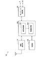
- FIG. 5 is a block diagram illustrating an example of a configuration of the small cell base station 20 according to the first embodiment.
- the small cell base station 20 includes a wireless communication unit 210, a network communication unit 220, a storage unit 230, and a control unit 240.
- the radio communication unit 210 provides the second radio communication service to the terminal device 30 located in the small cell 21 that is arranged so as to overlap the macro cell 11. For example, the radio communication unit 210 transmits a reference signal on the downlink channel. The reference signal is searched for by the terminal device 30 in the procedure of cell selection or cell reselection. Further, the terminal device 30 derives the communication quality for each cell, which is a basis for the handover determination, by executing measurement on the reference signal.
- the network communication unit 220 establishes a backhaul link with the macro cell base station 10 and mediates communication between the small cell base station 20 and the macro cell base station 10.
- the storage unit 230 stores a program and data for the operation of the small cell base station 20 using a storage medium such as a hard disk or a semiconductor memory.
- the control unit 240 controls the overall operation of the small cell base station 20 using a processor such as a CPU or DSP.
- the control unit 240 includes a communication control unit 242 and an operation mode setting unit 244.
- the communication control unit 242 controls the provision of the second wireless communication service. For example, the communication control unit 242 causes the uplink data traffic received by the wireless communication unit 210 to be transferred from the network communication unit 220 to the macro cell base station 10 depending on the destination. Further, the communication control unit 242 causes the wireless communication unit 210 to transmit downlink data traffic received from the other nodes by the network communication unit 220 to the destination terminal device 30. Further, the communication control unit 242 causes the wireless communication unit 210 to receive a report (for example, a measurement report or a CQI report) indicating downlink communication quality measured by the terminal device 30. Also, the communication control unit 242 causes the wireless communication unit 210 to measure uplink communication quality.
- a report for example, a measurement report or a CQI report
- the operation mode setting unit 244 sets the operation mode that can be selected from the operation mode set illustrated in FIGS. 4A to 4D in the small cell base station 20.
- the operation mode setting unit 244 sets the operation mode of the small cell base station 20 according to the control message. Transition.
- the communication control unit 242 When the operation mode setting unit 244 changes the operation mode of the wireless communication unit 210 from the first mode to the second mode with lower power consumption than the first mode, the communication control unit 242 The transmission power of the reference signal to be transmitted is lowered step by step.
- the reference signal here may be a reference signal of the component carrier to be deleted. Then, the communication control unit 242 waits for a predetermined time each time the transmission power of the reference signal is lowered by one step.
- the time length of the waiting time here may be, for example, a length corresponding to several transmission cycles of the reference signal.
- the terminal device 30 connected to the second wireless communication service executes handover, cell selection or cell reselection, and changes the connection destination from the small cell base station 20 to another base station ( Or switching from a component carrier to be deleted to another component carrier).
- the communication control unit 242 confirms the number of terminal devices 30 using the second wireless communication service while gradually reducing the transmission power of the reference signal, and after the number of the terminal devices 30 becomes zero
- the operation mode of the wireless communication unit 210 is switched to the second mode. Through such a procedure, the small cell base station 20 can change the operation mode of the power consumption without causing the connected terminal to become incapable of communication without passively waiting until there is no active terminal connected. You can switch to a lower mode.
- the terminal it is possible to sense a situation as if the small cell base station 20 is moving far away (whether it is away from the small cell base station 20).
- Such a mechanism does not depend on whether handover, cell selection, or cell reselection is performed independently on the terminal side or controlled on the network side. Therefore, for example, the mechanism described above is useful even when compared with a method in which the small cell base station 20 issues a forced handover command to the terminal device 30.
- the one-step reduction width of the reference signal transmission power may be a fixed value such as 5 dB, for example.
- the reduction width is a value that varies depending on the absolute value of the transmission power (for example, 5 dB if the transmission power is within a range of -20 dBm to ⁇ 0 dBm, and a transmission power of ⁇ 60 dBm to -20 dBm). It may be 2 dB as long as it is within the range.
- the communication control unit 242 may dynamically set the reduction amount of one step of the transmission power depending on parameters such as the number of connected terminals or communication quality. Thereby, it is possible to achieve an optimum balance between the smooth transition of the operation mode and the time required to complete the mode transition.
- the communication control unit 242 switches the operation mode according to an instruction included in the control message received from the macro cell base station 10 that monitors the load of the first wireless communication service.
- the wireless communication unit 210 When the wireless communication unit 210 is operating in the first mode, if it is determined that the load of the first wireless communication service is low, the operation mode is switched to the second mode.
- the wireless communication unit 210 When the wireless communication unit 210 is operating in the second mode, when it is determined that the load of the first wireless communication service is high, the operation mode is switched to the first mode.
- the logic for determining the condition relating to the load of the first wireless communication service only needs to be installed in the macrocell base station 10, the above-described mechanism can be realized at a relatively low cost.
- the communication control unit 242 determines that there is room for reducing the communication quality measured for the second wireless communication service in the small cell 21 regardless of the load of the first wireless communication service.
- the transmission power of the reference signal transmitted from the wireless communication unit 210 may be lowered without changing the operation mode. For example, when the communication quality reported from the terminal device 30 connected to the small cell base station 20 is well above a desired quality level, it can be determined that there is room for reducing the communication quality. In such a case, the power consumed by the small cell base station 20 can also be reduced by lowering the transmission power of the reference signal. Also, interference between the small cell and neighboring cells can be reduced.
- the wireless communication unit of the terminal device 30 selects a connection destination cell by executing a cell selection procedure after the power is turned on or after the wireless communication unit itself returns from the idle mode or the sleep mode to the active mode. Typically, in the cell selection procedure, all frequency channels are searched, and cell identification and reception power measurement are performed for each detected reference signal.
- the terminal device 30 uses the first wireless communication service provided by the macrocell base station 10.
- the terminal device 30 uses the second signal provided by the small cell base station 20. A wireless communication service will be used.
- the terminal device 30 may periodically measure the communication quality of the connection destination cell and one or more neighboring cells, and perform cell reselection. Further, when the communication quality measured for the connection destination cell and one or more neighboring cells satisfies the predetermined handover condition while operating in the active mode, the terminal device 30 performs the handover procedure.
- the connection destination cell may be switched.
- the control unit of the terminal device 30 controls the execution of such cell selection, cell reselection, and handover.
- the terminal device 30 is currently connected to the small cell base station 20.
- the reference signal received by the terminal device 30 in the process in which the operation mode of the small cell base station 20 transitions from the first mode to the second mode that consumes less power than the first mode.
- the transmission power is gradually reduced.
- the terminal device 30 continuously measures the received power of the reference signal from the small cell base station 20 (and the communication quality depending on the received power). Then, at a certain timing, the terminal device 30 switches the connection destination of the wireless communication unit from the small cell base station 20 that is the current serving base station to another base station (or switches the primary CC to another CC). During such a procedure, the terminal device 30 does not lose a packet and does not fall into communication failure.
- the small cell base station 20 can operate in an active mode and an idle mode.
- the small cell base station 20 can operate in a high aggregation mode, a low aggregation mode, and an idle mode.
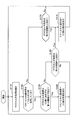
- FIG. 6A is a flowchart illustrating an example of a flow in a first scenario of communication control processing executed by the macrocell base station 10 according to the first embodiment.
- the communication control process shown in FIG. 6A is a process that can be periodically executed for one small cell base station 20. Actually, the communication control process described here may be executed for each of the one or more small cell base stations 20.
- the load monitoring unit 144 aggregates the latest load of the first wireless communication service provided in the macro cell 11 (step S110).
- the load of the first radio communication service may be aggregated from an arbitrary viewpoint such as the traffic volume, the number of radio bearers, the number of connected terminals, or communication quality.
- step S120 The subsequent processing branches depending on whether the small cell base station 20 is currently operating in the active mode or the idle mode.
- the load monitoring unit 144 compares the load of the macro cell 11 counted in step S110 with the first threshold (step S130).
- the small cell control unit 146 instructs the small cell base station 20 to change the operation mode to the idle mode (step S135).
- the load monitoring unit 144 compares the load of the macro cell 11 counted in Step S110 with a second threshold value that is larger than the first threshold value (Step S110). S140). When the load on the macro cell 11 exceeds the second threshold, the small cell control unit 146 instructs the small cell base station 20 to change the operation mode to the active mode (step S145).
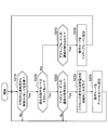
- FIG. 6B is a flowchart illustrating an example of a flow in a second scenario of communication control processing executed by the macro cell base station 10 according to the first embodiment.
- the communication control process shown in FIG. 6B is a process that can be periodically executed for one small cell base station 20. Actually, the communication control process described here may be executed for each of the one or more small cell base stations 20.
- the load monitoring unit 144 aggregates the latest load of the first wireless communication service provided in the macro cell 11 (step S110).
- the load of the first radio communication service may be aggregated from an arbitrary viewpoint such as the traffic volume, the number of radio bearers, the number of connected terminals, or communication quality.
- the subsequent processing branches depending on whether the small cell base station 20 is currently using one or more component carriers (step S150).
- the load monitoring unit 144 uses the first threshold corresponding to the number of CCs at that time to calculate the load of the macro cell 11 counted in step S110.
- the small cell control unit 146 instructs the small cell base station 20 to reduce the number of CCs (delete any CC) (step S160). ).
- the operation mode of the small cell base station 20 transitions from the high aggregation mode to the low aggregation mode, or from the low aggregation mode to the idle mode.
- the determination threshold for the former transition may be different from the determination threshold for the latter transition.
- the load monitoring unit 144 compares the load on the macro cell 11 with a second threshold that is greater than the first threshold (step S165).
- the small cell control unit 146 instructs the small cell base station 20 to increase the number of CCs (add a new CC) (step S175). .
- the operation mode of the small cell base station 20 transits from the low aggregation mode to the high aggregation mode. If the small cell base station 20 is already operating in the high aggregation mode, the determination in step S165 may be skipped.
- the load monitoring unit 144 compares the load of the macro cell 11 with the third threshold (Step S140).
- the small cell control unit 146 instructs the small cell base station 20 to increase the number of CCs (add a new CC) (step S175). .
- the operation mode of the small cell base station 20 transits from the idle mode to the low aggregation mode or the high aggregation mode.
- FIG. 7A is a flowchart illustrating an example of a flow in a first scenario of communication control processing executed by the small cell base station 20 according to the first embodiment.
- the operation mode setting unit 244 waits for reception of a control message from the macrocell base station 10 (step S210).
- the network communication unit 220 receives a control message instructing the operation mode transition from the macrocell base station 10, the process proceeds to step S220.
- step S220 The subsequent processing branches depending on whether the small cell base station 20 is currently operating in the active mode or the idle mode.
- the operation mode setting unit 244 determines whether or not the transition to the idle mode is instructed by the control message (step S225).
- the communication control unit 242 decreases the transmission power of the reference signal transmitted from the wireless communication unit 210 in a stepwise manner (Step S230). Then, the operation mode setting unit 244 sets the operation mode of the small cell base station 20 to the idle mode (step S235).
- the operation mode setting unit 244 determines whether the transition to the active mode is instructed by the control message (step S240). When the transition to the active mode is instructed, the operation mode setting unit 244 sets the operation mode of the small cell base station 20 to the active mode (step S245).
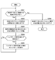
- FIG. 8A is a flowchart showing an example of a detailed flow of processing corresponding to step S230 of FIG. 7A.
- the communication control unit 242 determines whether there is a terminal device 30 using the second wireless communication service in the small cell 21 (step S231). Here, when there is no terminal device 30 using the second wireless communication service, the communication control unit 242 reduces the transmission power of the reference signal transmitted from the wireless communication unit 210 to zero (step S236).
- the communication control unit 242 reduces the transmission power of the reference signal transmitted from the wireless communication unit 210 by one level (step S232). Then, the communication control unit 242 waits for a predetermined time in order to switch the connection destination of the terminal device 30 (step S233). During this time, cell selection or cell reselection by the terminal device 30 can be executed.
- the communication control unit 242 executes a handover to the target base station in cooperation with the terminal device 30. (Step S235).
- the handover procedure may include, for example, reception of a measurement report from the terminal device 30, handover determination, transmission of an RRC connection reconfiguration message (RRCConnectionReconfigurationComplete), and reception of an RRC connection reconfiguration complete message (RRCConnectionReconfigurationComplete).
- step S231 the processing returns to step S231, and the above-described processing is repeated until there is no terminal device 30 using the second wireless communication service.
- FIG. 7B is a flowchart illustrating an example of a flow in a second scenario of communication control processing executed by the small cell base station 20 according to the first embodiment.
- the operation mode setting unit 244 waits for reception of a control message from the macrocell base station 10 (step S250).
- the network communication unit 220 receives a control message instructing change of the number of CCs from the macrocell base station 10, the process proceeds to step S255.
- the communication control unit 242 gradually reduces the transmission power of the reference signal transmitted in the CC to be deleted (step S260).
- the operation mode setting unit 244 changes the operation mode of the small cell base station 20 from the high aggregation mode to the low aggregation mode, or from the low aggregation mode to the idle mode by deleting the CC (step S265).
- the operation mode setting unit 244 adds a new CC to change the operation mode of the small cell base station 20 from the low aggregation mode to the high aggregation mode or from the idle mode to the low aggregation mode.
- the mode is changed (step S270).
- step S265 and step S270 is signaled, for example, by transmission of an RRC connection reconfiguration message from the communication control unit 242 to the terminal device 30.
- the RRC connection reconfiguration message may include system information regarding the component carrier to be deleted or added.
- FIG. 8B is a flowchart showing an example of a detailed flow of processing corresponding to step S260 of FIG. 7B.
- the communication control unit 242 determines whether there is a terminal device 30 connected to the CC to be deleted in the small cell 21 (step S261). Here, when there is no terminal device 30 connected to the CC to be deleted, the communication control unit 242 reduces the transmission power of the reference signal transmitted in the CC to zero (step S266).
- the communication control unit 242 lowers the transmission power of the reference signal transmitted in the CC by one step (step S262). Then, the communication control unit 242 waits for a predetermined time to switch the connection destination of the terminal device 30 (step S263). During this time, cell selection or cell reselection by the terminal device 30 can be executed.
- the communication control unit 242 cooperates with the terminal device 30 to perform handover between CCs or target base station. A handover to is executed (step S265).
- step S261 the processing returns to step S261, and the above-described processing is repeated until there is no terminal device 30 connected to the CC to be deleted.
- the macro cell base station 10 provides an index relating to the load of the first wireless communication service to the small cell base station 20, and the small cell base station 20 determines the necessity of changing the operation mode. judge.
- FIG. 9 is a block diagram illustrating an example of a configuration of the macro cell base station 10 according to the second embodiment.
- the macro cell base station 10 includes a radio communication unit 110, a network communication unit 120, a storage unit 130, and a control unit 160.
- the control unit 160 controls the overall operation of the macrocell base station 10 using a processor such as a CPU or a DSP.
- the control unit 160 includes a communication control unit 162 and an information management unit 166.
- the communication control unit 162 controls the provision of the first wireless communication service. For example, the communication control unit 162 determines the uplink data traffic received by the wireless communication unit 110 from the network communication unit 120 to the core network 5 or another macro cell base station or small cell base station depending on the destination. 20 is transferred. In addition, the communication control unit 162 causes downlink data traffic received from the other node by the network communication unit 120 to be transmitted from the wireless communication unit 110 to the destination terminal device 30. Further, the communication control unit 162 causes the wireless communication unit 110 to receive a report (for example, a measurement report or a CQI report) indicating downlink communication quality measured by the terminal device 30. Also, the communication control unit 162 causes the wireless communication unit 110 to measure the uplink communication quality.
- a report for example, a measurement report or a CQI report
- the information management unit 166 manages information supplied from the macro cell base station 10 to one or more small cell base stations 20. For example, the information management unit 166 generates information on the load of the first wireless communication service provided by the macrocell base station 10, and sends a control message indicating the generated information to the small via the network communication unit 120 and the backhaul link. Transmit to the cell base station 20.
- three methods for generating information related to the load of the first wireless communication service will be described with reference to FIGS. 10A to 10C.
- FIG. 10A is a block diagram illustrating a first example of a detailed configuration of the information management unit 166 illustrated in FIG.
- the information management unit 166 includes a traffic information generation unit 171 and a signaling unit 172.
- the traffic information generation unit 171 adds up the amount of uplink traffic and downlink traffic processed by the wireless communication unit 110 for each time window.
- the length of the time window may be defined in advance, for example, in units of slots, subframes, or radio frames.
- the aggregated traffic volume may be a total traffic volume, a time average, a moving average, or a maximum value in each time window.
- the traffic information generation unit 171 typically normalizes the latest aggregated traffic amount with the maximum value corresponding to the capacity of the macro cell 11 and outputs an index indicating the normalized traffic amount to the signaling unit 172. .
- the signaling unit 172 performs signaling with the small cell base station 20. For example, when an index indicating the traffic volume is input from the traffic information generation unit 171, the signaling unit 172 generates a control message indicating the index and transmits the generated control message to the small cell base station 20. The transmission of the control message may be performed in response to a request from the small cell base station 20.
- FIG. 10B is a block diagram showing a second example of a detailed configuration of the information management unit 166 shown in FIG.
- the information management unit 166 includes a bearer information generation unit 174 and a signaling unit 175.
- the bearer information generation unit 174 counts the number of active radio bearers established by the radio communication unit 110 for each time window.
- the length of the time window may be defined in advance, for example, in units of slots, subframes, or radio frames.
- the number of bearers to be aggregated may be a time average, a moving average, or a maximum value in each time window.
- the bearer information generation unit 174 typically normalizes the latest aggregation result of the number of radio bearers with the maximum value corresponding to the capacity of the macro cell 11, and sends an indicator indicating the normalized number of bearers to the signaling unit 175. Output. Note that the number of connected terminals may be used instead of the number of radio bearers.
- the signaling unit 175 performs signaling with the small cell base station 20. For example, when an index indicating the number of radio bearers is input from the bearer information generation unit 174, the signaling unit 175 generates a control message indicating the index, and transmits the generated control message to the small cell base station 20. The transmission of the control message may be performed in response to a request from the small cell base station 20.
- FIG. 10C is a block diagram illustrating a third example of a detailed configuration of the information management unit 166 illustrated in FIG.
- the information management unit 166 includes a quality information generation unit 177 and a signaling unit 178.
- the quality information generation unit 177 obtains the measurement result of the communication quality measured in the first wireless communication service from the wireless communication unit 110.
- the measurement result of communication quality acquired by the quality information generation unit 177 may be CQI.
- the quality information generation unit 177 aggregates the communication quality indicated by the CQI reported from the terminal for each time window.
- the length of the time window may be defined in advance, for example, in units of slots, subframes, or radio frames.
- the aggregated communication quality may be an average value in each time window. Then, the quality information generation unit 177 outputs the index indicating the aggregated communication quality or the acquired CQI itself to the signaling unit 178.
- the signaling unit 178 performs signaling with the small cell base station 20. For example, when an index indicating communication quality is input from the quality information generating unit 177, the signaling unit 178 generates a control message indicating the index and transmits the generated control message to the small cell base station 20. The transmission of the control message may be performed in response to a request from the small cell base station 20.
- the index relating to the load of the first wireless communication service supplied to the small cell base station 20 is used by the small cell base station 20 to control the operation mode of its own device. Is done. Also in this embodiment, the small cell base station 20 may be operable in the operation mode described with reference to FIGS. 4A to 4D or any other operation mode.
- FIG. 11 is a block diagram illustrating an example of a configuration of the small cell base station 20 according to the second embodiment.
- the small cell base station 20 includes a wireless communication unit 210, a network communication unit 220, a storage unit 235, and a control unit 260.
- the storage unit 235 stores a program and data for the operation of the small cell base station 20 using a storage medium such as a hard disk or a semiconductor memory.
- the data stored by the storage unit 235 may include, for example, a load indicator for the first wireless communication service received from the macrocell base station 10 and a set of threshold values to be compared with the load.
- the control unit 260 controls the overall operation of the small cell base station 20 using a processor such as a CPU or DSP.
- the control unit 260 includes a communication control unit 262 and an operation mode setting unit 264.
- the communication control unit 262 controls the provision of the second wireless communication service. For example, the communication control unit 262 causes the uplink data traffic received by the wireless communication unit 210 to be transferred from the network communication unit 220 to the macro cell base station 10 depending on the destination. Further, the communication control unit 262 causes the wireless communication unit 210 to transmit downlink data traffic received from the other nodes by the network communication unit 220 to the destination terminal device 30. Further, the communication control unit 262 causes the wireless communication unit 210 to receive a report (for example, a measurement report or a CQI report) indicating downlink communication quality measured by the terminal device 30. Further, the communication control unit 262 causes the wireless communication unit 210 to measure the uplink communication quality.
- a report for example, a measurement report or a CQI report
- the operation mode setting unit 264 sets, in the small cell base station 20, an operation mode that can be selected from the operation mode set illustrated in FIGS. 4A to 4D.
- the operation mode setting unit 264 transitions the operation mode of the small cell base station 20 based on the index related to the load of the first radio communication service indicated by the control message received from the macro cell base station 10.
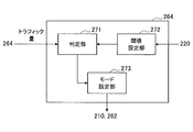
- FIG. 12A is a block diagram showing a first example of a detailed configuration of the operation mode setting unit 264 shown in FIG.
- the operation mode setting unit 264 includes a determination unit 271, a threshold setting unit 272, and a mode setting unit 273.
- the load of the first wireless communication service is determined based on the traffic amount of the first wireless communication service.
- the determination unit 271 acquires an index indicating the traffic amount included in the control message received from the macrocell base station 10. Then, the determination unit 271 satisfies the determination condition for changing the operation mode of the small cell base station 20 by comparing the traffic amount indicated by the acquired index with the threshold set by the threshold setting unit 272. Judge whether it is. For example, when the small cell base station 20 is operating in the first mode, the determination unit 271 determines whether to change the operation mode of the small cell base station 20 to the second mode with lower power consumption. In order to do so, it may be determined whether the latest traffic volume of the macro cell 11 is below the first threshold. When the latest traffic volume is lower than the first threshold, the load of the first wireless communication service is sufficiently low.
- the determination unit 271 determines whether to change the operation mode of the small cell base station 20 to the first mode. It may be determined whether the 11 latest traffic volumes are above the second threshold. When the latest traffic volume exceeds the second threshold, the load of the first wireless communication service is considerably high. Therefore, the load is distributed by shifting the operation mode of the small cell base station 20 to the first mode. be able to. If the determination unit 271 determines that the determination condition is satisfied, the determination unit 271 outputs the determination result to the mode setting unit 273.
- the threshold setting unit 272 sets a threshold that constitutes a determination condition for determining the load of the first wireless communication service in the determination unit 271.
- the threshold setting unit 272 may set a fixed threshold. Instead, the threshold setting unit 272 sets a threshold specified by a control message received from another node (for example, the control node in the macro cell base station 10 or the core network 5) via the network communication unit 220, for example.
- the determination unit 271 may be set. As described above, when the traffic volume is normalized, the threshold value compared with the normalized traffic volume takes a value within a range from zero to one.
- the first threshold value compared with the traffic amount of the first wireless communication service for switching from the first mode (for example, active mode) to the second mode (for example, idle mode) is the second threshold value.
- the value may be lower than a second threshold value for switching from the mode to the first mode.
- the mode setting unit 273 changes the operation mode of the small cell base station 20 according to the determination result about the operation mode transition input from the determination unit 271.
- the communication control unit 262 transmits from the wireless communication unit 210.
- the transmission power of the reference signal to be transmitted is lowered step by step.
- the reference signal here may be a reference signal of the component carrier to be deleted.
- the communication control unit 262 waits for a predetermined time each time the transmission power of the reference signal is lowered by one step.
- the time length of the waiting time here may be, for example, a length corresponding to several transmission cycles of the reference signal.
- the terminal device 30 connected to the second wireless communication service executes handover, cell selection or cell reselection, and changes the connection destination from the small cell base station 20 to another base station ( Or switching from a component carrier to be deleted to another component carrier).
- the communication control unit 262 confirms the number of terminal devices 30 using the second wireless communication service while gradually reducing the transmission power of the reference signal, and after the number of the terminal devices 30 becomes zero
- the operation mode of the wireless communication unit 210 is switched to the second mode.
- FIG. 12B is a block diagram showing a second example of a detailed configuration of the operation mode setting unit 264 shown in FIG.
- the operation mode setting unit 264 includes a determination unit 274, a threshold setting unit 275, and a mode setting unit 273.
- the load of the first radio communication service is determined based on the number of radio bearers in the first radio communication service. Note that the number of connected terminals may be used instead of the number of radio bearers.
- the determination unit 274 acquires an index indicating the number of radio bearers included in the control message received from the macro cell base station 10. And the determination part 274 compares the number of the radio bearers shown by the acquired parameter
- the determination unit 274 determines whether to change the operation mode of the small cell base station 20 to the first mode. It may be determined whether the number of eleven latest radio bearers exceeds a second threshold. When the number of the latest radio bearers exceeds the second threshold, the load of the first radio communication service is considerably high. Therefore, the load is reduced by shifting the operation mode of the small cell base station 20 to the first mode. Can be dispersed. If the determination unit 274 determines that the determination condition is satisfied, the determination unit 274 outputs the determination result to the mode setting unit 273.
- the threshold setting unit 275 sets a threshold that constitutes a determination condition for determining the load of the first wireless communication service in the determination unit 274.
- the threshold setting unit 275 may set a fixed threshold. Instead, the threshold setting unit 275 may set, for example, a threshold specified by a control message received from another node via the network communication unit 220 in the determination unit 274. As described above, when the number of radio bearers is normalized, a threshold value compared with the number of radio bearers after the normalization takes a value within a range from zero to one.
- the first threshold compared with the number of radio bearers of the first radio communication service for switching from the first mode (eg, active mode) to the second mode (eg, idle mode) is It may be a value lower than a second threshold value for switching from the second mode to the first mode.
- FIG. 12C is a block diagram showing a third example of a detailed configuration of the operation mode setting unit 264 shown in FIG.
- the operation mode setting unit 264 includes a determination unit 277, a threshold setting unit 278, and a mode setting unit 273.
- the load of the first wireless communication service is determined based on the communication quality measured in the first wireless communication service.
- the determination unit 277 acquires an index indicating the communication quality included in the control message received from the macrocell base station 10. Then, the determination unit 277 compares the communication quality indicated by the acquired index with the threshold set by the threshold setting unit 278, thereby satisfying the determination condition for changing the operation mode of the small cell base station 20. Judge whether it is. For example, when the small cell base station 20 is operating in the first mode, the determination unit 277 determines whether to change the operation mode of the small cell base station 20 to the second mode with lower power consumption. In order to do so, it may be determined whether the communication quality of the first wireless communication service exceeds a predetermined threshold. The determination unit 277 may compare the number of terminals experiencing poor communication quality or the ratio of the terminals with a threshold value.
- the determination unit 277 may determine that the operation mode of the small cell base station 20 should be changed to the second mode.
- the determination unit 277 experiences poor communication quality when the communication quality of the first wireless communication service falls below a predetermined threshold.
- the determination unit 277 determines that the determination condition is satisfied, the determination unit 277 outputs the determination result to the mode setting unit 273.
- the threshold setting unit 278 sets a threshold that constitutes a determination condition for determining the load of the first wireless communication service in the determination unit 277.
- the threshold setting unit 278 may set a fixed threshold. Instead, the threshold setting unit 278 may set, for example, a threshold specified by a control message received from another node via the network communication unit 220 in the determination unit 277.
- the small cell base station 20 mainly determines whether the operation mode should be changed as in the present embodiment
- flexible operation mode control in accordance with the requirements of the individual small cell base stations 20 is possible. It becomes possible. Further, since the logic for determining the condition regarding the transition of the operation mode does not need to be installed in the macro cell base station 10, the mechanism described above is included in the wireless communication system 1 while minimizing the impact on the existing system. Can be introduced.
- the communication control unit 262 has room to reduce the communication quality measured for the second wireless communication service in the small cell 21 regardless of the load of the first wireless communication service.
- the transmission power of the reference signal transmitted from the wireless communication unit 210 may be lowered without changing the operation mode.
- the configuration of the terminal device 30 in the present embodiment may be the same as the configuration of the terminal device 30 described in relation to the first embodiment. That is, also in the present embodiment, the signal is received by the terminal device 30 in the process in which the operation mode of the small cell base station 20 transitions from the first mode to the second mode that consumes less power than the first mode. The transmission power of the reference signal is lowered step by step. The terminal device 30 switches the connection destination of the wireless communication unit from the small cell base station 20 that is the current serving base station to another base station (or switches the primary CC to another CC) at a certain timing therebetween. During such a procedure, the terminal device 30 does not lose a packet and does not fall into communication failure.
- FIG. 13 is a flowchart showing an example of the flow of communication control processing executed by the macro cell base station according to the second embodiment.
- the information management unit 166 aggregates the latest load of the first wireless communication service provided in the macro cell 11 (step S310).
- the load of the first radio communication service may be aggregated from an arbitrary viewpoint such as the traffic volume, the number of radio bearers, the number of connected terminals, or communication quality.
- the information management unit 166 generates a control message including an index related to the load of the first wireless communication service (step S320).
- the information management part 166 transmits the produced
- step S310 the processing returns to step S310, and the above-described processing can be repeated at a constant cycle.
- the process illustrated in FIG. 13 may be executed at least partially in response to a request received from the small cell base station 20.
- the small cell base station 20 can operate in an active mode and an idle mode.
- the small cell base station 20 can operate in a high aggregation mode, a low aggregation mode, and an idle mode.
- FIG. 14A is a flowchart illustrating an example of a flow in a first scenario of communication control processing executed by the small cell base station 20 according to the second embodiment.
- the operation mode setting unit 264 acquires an index related to the latest load of the first wireless communication service provided in the macro cell 11 from the control message received from the macro cell base station 10 (step S410).
- the load of the first wireless communication service may be determined based on an arbitrary viewpoint such as the traffic volume, the number of radio bearers, the number of connected terminals, or communication quality.
- the subsequent processing branches depending on whether the small cell base station 20 is currently operating in the active mode or the idle mode (step S420).
- the operation mode setting unit 264 compares the load of the macro cell 11 indicated by the index acquired in Step S410 with the first threshold (Step S430).
- the communication control unit 262 gradually decreases the transmission power of the reference signal transmitted from the wireless communication unit 210 (step S435).
- the stepwise reduction in transmission power here may be performed as described with reference to FIG. 8A.
- the operation mode setting unit 264 sets the operation mode of the small cell base station 20 to the idle mode (step S437).
- the operation mode setting unit 264 compares the load of the macro cell 11 counted in step S410 with a second threshold value that is larger than the first threshold value (Ste S440). If the load on the macro cell 11 exceeds the second threshold, the operation mode setting unit 264 sets the operation mode of the small cell base station 20 to the active mode (step S445).
- FIG. 14B is a flowchart illustrating an example of a flow in a second scenario of communication control processing executed by the small cell base station 20 according to the second embodiment.
- the operation mode setting unit 264 acquires an index related to the latest load of the first wireless communication service provided in the macro cell 11 from the control message received from the macro cell base station 10 (step S410).
- the load of the first wireless communication service may be determined based on an arbitrary viewpoint such as the traffic volume, the number of radio bearers, the number of connected terminals, or communication quality.
- step S450 The subsequent processing branches depending on whether the small cell base station 20 is currently using one or more component carriers.
- the operation mode setting unit 264 corresponds the load of the macro cell 11 indicated by the index acquired in step S410 to the number of CCs at that time. Compare with the first threshold value (step S455).
- the communication control unit 262 gradually decreases the transmission power of the reference signal transmitted in the CC to be deleted (step S460).
- the stepwise reduction in transmission power here may be performed as described with reference to FIG. 8B.
- the operation mode setting unit 264 transitions the operation mode of the small cell base station 20 from the high aggregation mode to the low aggregation mode, or from the low aggregation mode to the idle mode by deleting the CC (step S462). .
- the determination threshold for the former transition may be different from the determination threshold for the latter transition.
- the operation mode setting unit 264 compares the load on the macro cell 11 with a second threshold value that is greater than the first threshold value (step S465). When the load on the macro cell 11 exceeds the second threshold, the operation mode setting unit 264 transitions the operation mode of the small cell base station 20 from the low aggregation mode to the high aggregation mode by adding a new CC. (Step S475). If the small cell base station 20 is already operating in the high aggregation mode, the determination in step S465 may be skipped.
- the operation mode setting unit 264 compares the load of the macro cell 11 with the third threshold value (step S470). When the load on the macro cell 11 exceeds the third threshold value, the operation mode setting unit 264 adds a new CC to change the operation mode of the small cell base station 20 from the idle mode to the low aggregation mode or the high aggregation mode. (Step S475).
- the macro cell base station 10 and the small cell base station 20 may be realized as an eNB (evolved Node B) of the LTE scheme or the LTE-A scheme.
- the macro cell base station 10 and the small cell base station 20 may be realized as other types of base stations such as a Node B or a BTS (Base Transceiver Station).
- the macrocell base station 10 may include a main body (also referred to as a base station apparatus) that controls radio communication and one or more RRHs (Remote Radio Heads) that are arranged at locations different from the main body.
- the small cell base station 20 may be realized as a smaller base station, a wireless access point, or a mobile router.
- the terminal device 30 is a smartphone, a tablet PC (Personal Computer), a notebook PC, a portable game terminal, a mobile terminal such as a portable / dongle type mobile router or a digital camera, or an in-vehicle terminal such as a car navigation device. It may be realized as.
- the terminal device 30 may be realized as a terminal (also referred to as an MTC (Machine Type Communication) terminal) that performs M2M (Machine To Machine) communication.
- the terminal device 30 may be a wireless communication module (for example, an integrated circuit module configured by one die) mounted on these terminals.
- FIG. 15 is a block diagram illustrating a first example of a schematic configuration of an eNB to which the technology according to the present disclosure may be applied.
- the eNB 800 includes one or more antennas 810 and a base station device 820. Each antenna 810 and the base station apparatus 820 can be connected to each other via an RF cable.
- Each of the antennas 810 has a single or a plurality of antenna elements (for example, a plurality of antenna elements constituting a MIMO antenna), and is used for transmission and reception of radio signals by the base station apparatus 820.
- the eNB 800 includes a plurality of antennas 810 as illustrated in FIG. 15, and the plurality of antennas 810 may respectively correspond to a plurality of frequency bands used by the eNB 800, for example.
- FIG. 15 illustrates an example in which the eNB 800 includes a plurality of antennas 810, the eNB 800 may include a single antenna 810.
- the base station apparatus 820 includes a controller 821, a memory 822, a network interface 823, and a wireless communication interface 825.
- the controller 821 may be a CPU or a DSP, for example, and operates various functions of the upper layer of the base station apparatus 820. For example, the controller 821 generates a data packet from the data in the signal processed by the wireless communication interface 825, and transfers the generated packet via the network interface 823. The controller 821 may generate a bundled packet by bundling data from a plurality of baseband processors, and may transfer the generated bundled packet. In addition, the controller 821 is a logic that executes control such as radio resource control, radio bearer control, mobility management, inflow control, or scheduling. May have a typical function. Moreover, the said control may be performed in cooperation with a surrounding eNB or a core network node.
- the memory 822 includes RAM and ROM, and stores programs executed by the controller 821 and various control data (for example, terminal list, transmission power data, scheduling data, and the like).
- the network interface 823 is a communication interface for connecting the base station device 820 to the core network 824.
- the controller 821 may communicate with the core network node or other eNB via the network interface 823.
- the eNB 800 and the core network node or another eNB may be connected to each other by a logical interface (for example, an S1 interface or an X2 interface).
- the network interface 823 may be a wired communication interface or a wireless communication interface for wireless backhaul.
- the network interface 823 may use a frequency band higher than the frequency band used by the wireless communication interface 825 for wireless communication.
- the radio communication interface 825 supports any cellular communication scheme such as LTE or LTE-A, and provides a radio connection to a terminal located in the cell of the eNB 800 via the antenna 810.
- the wireless communication interface 825 may typically include a baseband (BB) processor 826, an RF circuit 827, and the like.
- the BB processor 826 may perform, for example, encoding / decoding, modulation / demodulation, and multiplexing / demultiplexing, and each layer (for example, L1, MAC (Medium Access Control), RLC (Radio Link Control), and PDCP).
- Various signal processing of Packet Data Convergence Protocol
- the BB processor 826 may have some or all of the logical functions described above instead of the controller 821.
- the BB processor 826 may be a module that includes a memory that stores a communication control program, a processor that executes the program, and related circuits. The function of the BB processor 826 may be changed by updating the program. Good. Further, the module may be a card or a blade inserted into a slot of the base station apparatus 820, or a chip mounted on the card or the blade.
- the RF circuit 827 may include a mixer, a filter, an amplifier, and the like, and transmits and receives a radio signal via the antenna 810.
- the wireless communication interface 825 includes a plurality of BB processors 826 as illustrated in FIG. 15, and the plurality of BB processors 826 may respectively correspond to a plurality of frequency bands used by the eNB 800, for example. Further, the wireless communication interface 825 includes a plurality of RF circuits 827 as illustrated in FIG. 15, and the plurality of RF circuits 827 may respectively correspond to a plurality of antenna elements, for example. 15 illustrates an example in which the wireless communication interface 825 includes a plurality of BB processors 826 and a plurality of RF circuits 827, the wireless communication interface 825 includes a single BB processor 826 or a single RF circuit 827. But you can.
- FIG. 16 is a block diagram illustrating a second example of a schematic configuration of an eNB to which the technology according to the present disclosure may be applied.
- the eNB 830 includes one or more antennas 840, a base station apparatus 850, and an RRH 860. Each antenna 840 and RRH 860 may be connected to each other via an RF cable. Base station apparatus 850 and RRH 860 can be connected to each other via a high-speed line such as an optical fiber cable.
- Each of the antennas 840 has a single or a plurality of antenna elements (for example, a plurality of antenna elements constituting a MIMO antenna), and is used for transmission / reception of radio signals by the RRH 860.
- the eNB 830 includes a plurality of antennas 840 as illustrated in FIG. 16, and the plurality of antennas 840 may respectively correspond to a plurality of frequency bands used by the eNB 830, for example. 16 shows an example in which the eNB 830 includes a plurality of antennas 840, but the eNB 830 may include a single antenna 840.
- the base station device 850 includes a controller 851, a memory 852, a network interface 853, a wireless communication interface 855, and a connection interface 857.
- the controller 851, the memory 852, and the network interface 853 are the same as the controller 821, the memory 822, and the network interface 823 described with reference to FIG.
- the wireless communication interface 855 supports a cellular communication method such as LTE or LTE-A, and provides a wireless connection to a terminal located in a sector corresponding to the RRH 860 via the RRH 860 and the antenna 840.
- the wireless communication interface 855 may typically include a BB processor 856 and the like.
- the BB processor 856 is the same as the BB processor 826 described with reference to FIG. 15 except that the BB processor 856 is connected to the RF circuit 864 of the RRH 860 via the connection interface 857.
- the wireless communication interface 855 includes a plurality of BB processors 856 as illustrated in FIG. 16, and the plurality of BB processors 856 may respectively correspond to a plurality of frequency bands used by the eNB 830, for example. 16 shows an example in which the wireless communication interface 855 includes a plurality of BB processors 856, the wireless communication interface 855 may include a single BB processor 856.
- connection interface 857 is an interface for connecting the base station device 850 (wireless communication interface 855) to the RRH 860.
- the connection interface 857 may be a communication module for communication on the high-speed line that connects the base station apparatus 850 (wireless communication interface 855) and the RRH 860.
- the RRH 860 includes a connection interface 861 and a wireless communication interface 863.
- connection interface 861 is an interface for connecting the RRH 860 (wireless communication interface 863) to the base station device 850.
- the connection interface 861 may be a communication module for communication on the high-speed line.
- the wireless communication interface 863 transmits and receives wireless signals via the antenna 840.
- the wireless communication interface 863 may typically include an RF circuit 864 and the like.
- the RF circuit 864 may include a mixer, a filter, an amplifier, and the like, and transmits and receives wireless signals via the antenna 840.
- the wireless communication interface 863 includes a plurality of RF circuits 864 as shown in FIG. 16, and the plurality of RF circuits 864 may correspond to, for example, a plurality of antenna elements, respectively. 16 illustrates an example in which the wireless communication interface 863 includes a plurality of RF circuits 864, the wireless communication interface 863 may include a single RF circuit 864.
- the functions related to the small cell control of the macro cell base station 10 described with reference to FIGS. 2 and 9 may be implemented in the radio communication interface 825, the radio communication interface 855, or the radio communication interface 863. Further, the function related to the small cell control of the macro cell base station 10 may be implemented in the controller 821 or the controller 851. For example, when the operation mode of the small cell arranged in the cell of the eNB 800 is shifted to the idle mode, the controller 821 may lower the transmission power of the reference signal from the small cell in a stepwise manner. Thereby, it is possible to actively reduce the power consumption of the small cell without causing a terminal existing in the vicinity of the small cell to be unable to communicate.
- the function related to the operation mode control of the small cell base station 20 described with reference to FIGS. 5 and 11 may be implemented in the radio communication interface 825 or may be implemented in the controller 821.
- the controller 821 may transition the operation mode of the radio communication interface 825 to the idle mode after gradually reducing the transmission power of the reference signal from the eNB 800. Thereby, it is possible to actively reduce the power consumption of the eNB 800 without causing a terminal existing in the vicinity of the eNB 800 to be unable to communicate.
- FIG. 17 is a block diagram illustrating an example of a schematic configuration of a smartphone 900 to which the technology according to the present disclosure can be applied.
- the smartphone 900 includes a processor 901, a memory 902, a storage 903, an external connection interface 904, a camera 906, a sensor 907, a microphone 908, an input device 909, a display device 910, a speaker 911, a wireless communication interface 912, one or more antenna switches 915.
- One or more antennas 916, a bus 917, a battery 918 and an auxiliary controller 919 are provided.
- the processor 901 may be, for example, a CPU or a SoC (System on Chip), and controls the functions of the application layer and other layers of the smartphone 900.
- the memory 902 includes a RAM and a ROM, and stores programs executed by the processor 901 and data.
- the storage 903 can include a storage medium such as a semiconductor memory or a hard disk.
- the external connection interface 904 is an interface for connecting an external device such as a memory card or a USB (Universal Serial Bus) device to the smartphone 900.
- the camera 906 includes, for example, an image sensor such as a CCD (Charge Coupled Device) or a CMOS (Complementary Metal Oxide Semiconductor), and generates a captured image.
- the sensor 907 may include a sensor group such as a positioning sensor, a gyro sensor, a geomagnetic sensor, and an acceleration sensor.
- the microphone 908 converts sound input to the smartphone 900 into an audio signal.
- the input device 909 includes, for example, a touch sensor that detects a touch on the screen of the display device 910, a keypad, a keyboard, a button, or a switch, and receives an operation or information input from a user.
- the display device 910 has a screen such as a liquid crystal display (LCD) or an organic light emitting diode (OLED) display, and displays an output image of the smartphone 900.
- the speaker 911 converts an audio signal output from the smartphone 900 into audio.
- the wireless communication interface 912 supports any cellular communication method such as LTE or LTE-A and performs wireless communication.
- the wireless communication interface 912 may typically include a BB processor 913, an RF circuit 914, and the like.
- the BB processor 913 may perform, for example, encoding / decoding, modulation / demodulation, and multiplexing / demultiplexing, and performs various signal processing for wireless communication.
- the RF circuit 914 may include a mixer, a filter, an amplifier, and the like, and transmits and receives radio signals via the antenna 916.
- the wireless communication interface 912 may be a one-chip module in which the BB processor 913 and the RF circuit 914 are integrated.
- the wireless communication interface 912 may include a plurality of BB processors 913 and a plurality of RF circuits 914 as illustrated in FIG.
- FIG. 17 shows an example in which the wireless communication interface 912 includes a plurality of BB processors 913 and a plurality of RF circuits 914.
- the wireless communication interface 912 includes a single BB processor 913 or a single RF circuit 914. But you can.
- the wireless communication interface 912 may support other types of wireless communication methods such as a short-range wireless communication method, a proximity wireless communication method, or a wireless LAN (Local Area Network) method in addition to the cellular communication method.
- a BB processor 913 and an RF circuit 914 for each wireless communication method may be included.
- Each of the antenna switches 915 switches the connection destination of the antenna 916 among a plurality of circuits (for example, circuits for different wireless communication systems) included in the wireless communication interface 912.
- Each of the antennas 916 includes a single or a plurality of antenna elements (for example, a plurality of antenna elements constituting a MIMO antenna), and is used for transmission / reception of a radio signal by the radio communication interface 912.
- the smartphone 900 may include a plurality of antennas 916 as illustrated in FIG. Note that although FIG. 17 illustrates an example in which the smartphone 900 includes a plurality of antennas 916, the smartphone 900 may include a single antenna 916.
- the smartphone 900 may include an antenna 916 for each wireless communication method.
- the antenna switch 915 may be omitted from the configuration of the smartphone 900.
- the bus 917 connects the processor 901, the memory 902, the storage 903, the external connection interface 904, the camera 906, the sensor 907, the microphone 908, the input device 909, the display device 910, the speaker 911, the wireless communication interface 912, and the auxiliary controller 919 to each other.
- the battery 918 supplies electric power to each block of the smartphone 900 shown in FIG. 17 through a power supply line partially shown by a broken line in the drawing.
- the auxiliary controller 919 operates the minimum necessary functions of the smartphone 900 in the sleep mode.
- the wireless communication interface 912 of the smartphone 900 illustrated in FIG. 17 may have a function of executing cell selection, cell reselection, and handover of the terminal device 30 described above.
- at least a part of these functions may be implemented in the processor 901 or the auxiliary controller 919.
- the smartphone 900 performs handover to another base station, thereby smoothly transitioning the small cell base station to the idle mode. be able to.
- the smartphone 900 may operate as a small cell base station when the processor 901 executes the access point function. Further, the wireless communication interface 913 may have a function as a small cell base station.
- FIG. 18 is a block diagram illustrating an example of a schematic configuration of a car navigation device 920 to which the technology according to the present disclosure can be applied.
- the car navigation device 920 includes a processor 921, a memory 922, a GPS (Global Positioning System) module 924, a sensor 925, a data interface 926, a content player 927, a storage medium interface 928, an input device 929, a display device 930, a speaker 931, and wireless communication.
- the interface 933 includes one or more antenna switches 936, one or more antennas 937, and a battery 938.
- the processor 921 may be a CPU or SoC, for example, and controls the navigation function and other functions of the car navigation device 920.
- the memory 922 includes RAM and ROM, and stores programs and data executed by the processor 921.
- the GPS module 924 measures the position (for example, latitude, longitude, and altitude) of the car navigation device 920 using GPS signals received from GPS satellites.
- the sensor 925 may include a sensor group such as a gyro sensor, a geomagnetic sensor, and an atmospheric pressure sensor.
- the data interface 926 is connected to the in-vehicle network 941 through a terminal (not shown), for example, and acquires data generated on the vehicle side such as vehicle speed data.
- the content player 927 reproduces content stored in a storage medium (for example, CD or DVD) inserted into the storage medium interface 928.
- the input device 929 includes, for example, a touch sensor, a button, or a switch that detects a touch on the screen of the display device 930, and receives an operation or information input from the user.
- the display device 930 has a screen such as an LCD or an OLED display, and displays a navigation function or an image of content to be reproduced.
- the speaker 931 outputs the navigation function or the audio of the content to be played back.
- the wireless communication interface 933 supports any cellular communication method such as LTE or LTE-A, and performs wireless communication.
- the wireless communication interface 933 may typically include a BB processor 934, an RF circuit 935, and the like.
- the BB processor 934 may perform, for example, encoding / decoding, modulation / demodulation, and multiplexing / demultiplexing, and performs various signal processing for wireless communication.
- the RF circuit 935 may include a mixer, a filter, an amplifier, and the like, and transmits and receives a radio signal via the antenna 937.
- the wireless communication interface 933 may be a one-chip module in which the BB processor 934 and the RF circuit 935 are integrated.
- the wireless communication interface 933 may include a plurality of BB processors 934 and a plurality of RF circuits 935 as shown in FIG. 18 shows an example in which the wireless communication interface 933 includes a plurality of BB processors 934 and a plurality of RF circuits 935, the wireless communication interface 933 includes a single BB processor 934 or a single RF circuit 935. But you can.
- the wireless communication interface 933 may support other types of wireless communication methods such as a short-range wireless communication method, a proximity wireless communication method, or a wireless LAN method in addition to the cellular communication method.
- a BB processor 934 and an RF circuit 935 may be included for each communication method.
- Each of the antenna switches 936 switches the connection destination of the antenna 937 among a plurality of circuits included in the wireless communication interface 933 (for example, circuits for different wireless communication systems).
- Each of the antennas 937 has a single or a plurality of antenna elements (for example, a plurality of antenna elements constituting a MIMO antenna), and is used for transmission / reception of a radio signal by the radio communication interface 933.
- the car navigation device 920 may include a plurality of antennas 937 as shown in FIG. 18 illustrates an example in which the car navigation apparatus 920 includes a plurality of antennas 937, the car navigation apparatus 920 may include a single antenna 937.
- the car navigation device 920 may include an antenna 937 for each wireless communication method.
- the antenna switch 936 may be omitted from the configuration of the car navigation device 920.
- the battery 938 supplies power to each block of the car navigation apparatus 920 shown in FIG. 18 through a power supply line partially shown by a broken line in the figure. Further, the battery 938 stores electric power supplied from the vehicle side.
- the radio communication interface 933 of the car navigation device 940 illustrated in FIG. 18 may have a function of executing cell selection, cell reselection, and handover of the terminal device 30 described above. Further, at least a part of these functions may be implemented in the processor 921. For example, when the car navigation device 940 is handed over to another base station while the transmission power of the reference signal from the small cell base station is gradually reduced, the transition to the idle mode of the small cell base station is smoothly performed. Can be done.
- the technology according to the present disclosure may be realized as an in-vehicle system (or vehicle) 940 including one or more blocks of the car navigation device 920 described above, an in-vehicle network 941, and a vehicle side module 942.
- vehicle-side module 942 generates vehicle-side data such as vehicle speed, engine speed, or failure information, and outputs the generated data to the in-vehicle network 941.
- the second base station provides the second wireless communication service in the cell in which the first base station provides the first wireless communication service
- the second base station When the operation mode is changed from the first mode to the second mode that consumes less power than the first mode, the operation mode is set after stepwise reducing the transmission power of the reference signal transmitted to the terminal device. To the second mode. Therefore, the second base station can smoothly switch the operation mode to a mode with low power consumption without passively waiting until there is no active terminal connected to its own device. That is, further power saving in the heterogeneous network can be realized.
- the second base station waits for a time for the terminal device connected to the second wireless communication service to switch the connection destination each time the transmission power is reduced by one step. That is, the terminal apparatus is given a time delay for executing handover, cell selection, or cell reselection by evaluating the received power of the lowered reference signal. Thereby, it is possible to prevent the terminal device connected to the second base station from becoming incapable of communication due to the transition of the operation mode of the second base station.
- the second base station when it is determined that the load of the first wireless communication service is low, the second base station The operation mode is switched to the second mode. Therefore, a system in which the second base station (for example, small cell base station) is operated in the first mode with high power consumption while the load on the first base station (for example, macro cell base station) is not so high. A situation that is not efficient in terms of overall power consumption can be avoided.
- the second base station for example, small cell base station
- the load on the first base station for example, macro cell base station
- the first mode is an active mode in which the wireless communication unit operates continuously
- the second mode is an idle mode or a sleep mode in which the wireless communication unit operates at least intermittently.
- power saving of the second base station or the entire system is realized as a result of shortening the time during which power is supplied to the radio communication unit of the second base station.
- the first mode is a mode in which a plurality of component carriers are used for the second wireless communication service, and the second mode uses a smaller number of component carriers than the first mode. Mode. In this case, as a result of reducing the amount of power consumed in the radio communication unit of the second base station, power saving of the second base station or the entire system is realized.
- a series of control processing by each device described in this specification may be realized using any of software, hardware, and a combination of software and hardware.
- the program constituting the software is stored in advance in a storage medium (non-transitory medium) provided inside or outside each device.
- Each program is read into a RAM (Random Access Memory) at the time of execution and executed by a processor such as a CPU.
- processing described using the flowchart in this specification does not necessarily have to be executed in the order shown in the flowchart. Some processing steps may be performed in parallel. Further, additional processing steps may be employed, and some processing steps may be omitted.
- a wireless communication unit that provides a second wireless communication service in a cell in which the first base station provides the first wireless communication service;
- the transmission power of the reference signal transmitted from the wireless communication unit is stepwise
- a control unit that switches the operation mode to the second mode after being pulled down to
- a communication control device comprising: (2) When the control unit transitions the operation mode from the first mode to the second mode, a terminal device connected to the second wireless communication service every time the transmission power is reduced by one step.
- the control unit switches the operation mode to the second mode when the index acquired from the first base station indicates that the load of the first wireless communication service is low, (4) The communication control device according to 1.
- the control unit changes the operation mode to the first mode when it is determined that the load of the first wireless communication service is high when the wireless communication unit is operating in the second mode.
- the communication control device according to any one of (1) to (9), wherein the communication control device is switched to (1).
- the first threshold compared with the load of the first wireless communication service for switching from the first mode to the second mode is from the second mode to the first mode.
- the communication control device according to (10) which is lower than a second threshold value compared with the load of the first wireless communication service for switching.
- the first mode is a mode in which the wireless communication unit operates continuously
- the second mode is a mode in which the wireless communication unit operates intermittently.
- the communication control device according to any one of (1) to (11).
- the communication control apparatus wherein the control unit also intermittently operates in the second mode.
- the first mode is a mode in which a plurality of component carriers are used for the second wireless communication service
- the second mode is a mode in which a smaller number of component carriers are used for the second wireless communication service than in the first mode.
- the communication control apparatus according to any one of (1) to (13).
- the control unit lowers the transmission power of the reference signal of the component carrier to be deleted in a stepwise manner when the operation mode is changed from the first mode to the second mode.
- the control unit reduces the transmission power of the reference signal when it is determined that there is room to reduce the communication quality measured in the second wireless communication service.
- the communication control apparatus according to claim 1.
- a first base station that provides a first wireless communication service
- a wireless communication unit for providing a second wireless communication service within the cell of the first wireless communication service
- the transmission power of the reference signal transmitted from the wireless communication unit is stepwise
- a control unit that switches the operation mode to the second mode after being pulled down to
- a second base station comprising: A wireless communication system including: (19) A wireless communication unit that uses the second wireless communication service provided by the second base station in a cell in which the first base station provides the first wireless communication service; The transmission power of the reference signal received by the wireless communication unit in the process in which the operation mode of the second base station transitions from the first mode to the second mode that consumes less power than the first mode.
- a control unit that switches the connection destination of the wireless communication unit from the second base station to another base station A terminal device comprising: (20) A wireless communication unit for providing a first wireless communication service in a cell; When the operation mode of the second base station that provides the second wireless communication service in the cell is changed from the first mode to the second mode that consumes less power than the first mode, A control unit that causes the second base station to switch the operation mode to the second mode after gradually reducing the transmission power of the reference signal transmitted from the second base station;
- a communication control device comprising:
- first base station (macrocell base station) 110 wireless communication unit 140, 160 control unit 20 second base station (small cell base station) 210 wireless communication unit 240, 260 control unit 30 terminal device
Landscapes
- Engineering & Computer Science (AREA)
- Computer Networks & Wireless Communication (AREA)
- Signal Processing (AREA)
- Mobile Radio Communication Systems (AREA)
Abstract
Description
なお、上記の効果は必ずしも限定的なものではなく、上記の効果と共に、又は上記の効果に代えて、本明細書に示されたいずれかの効果、又は本明細書から把握され得る他の効果が奏されてもよい。
1.システムの概要
2.第1の実施形態
2-1.マクロセル基地局の構成例
2-2.スモールセル基地局の構成例
2-3.端末装置の構成例
2-4.処理の流れ(マクロセル基地局)
2-5.処理の流れ(スモールセル基地局)
3.第2の実施形態
3-1.マクロセル基地局の構成例
3-2.スモールセル基地局の構成例
3-3.端末装置の構成例
3-4.処理の流れ(マクロセル基地局)
3-5.処理の流れ(スモールセル基地局)
4.応用例
5.まとめ
図1A~図1Cは、本開示に係る技術が適用される無線通信システム1の概要について説明するための説明図である。図1Aを参照すると、無線通信システム1は、マクロセル基地局10、スモールセル基地局20b及び20c、並びに端末装置30a、30b及び30cを含む。なお、無線通信システム1に含まれるマクロセル基地局の数、スモールセル基地局の数及び端末装置の数は、図1Aの例には限定されない。例えば、無線通信システム1は、2つ以上のマクロセル基地局を含んでもよい。
本節で説明する第1の実施形態では、マクロセル基地局10が第1の無線通信サービスの負荷を監視し、動作モードの変更の必要性を判定する。スモールセル基地局20は、マクロセル基地局10からの指示に応じて、自装置の動作モードを複数のモードの間で遷移させる。
図2は、第1の実施形態に係るマクロセル基地局10の構成の一例を示すブロック図である。図2を参照すると、マクロセル基地局10は、無線通信部110、ネットワーク通信部120、記憶部130及び制御部140を含む。
無線通信部110は、マクロセル11内に位置する端末装置30へ、第1の無線通信サービスを提供する。例えば、無線通信部110は、ダウンリンクチャネル上でリファレンス信号(ビーコン信号、パイロット信号又は同期信号ともいう)を送信する。当該リファレンス信号は、セル選択又はセル再選択の手続の中で端末装置30によって探索される。また、端末装置30は、ハンドオーバ判定の基礎となるセルごとの通信品質を、当該リファレンス信号についてメジャメントを実行することにより導出する。無線通信部110は、マクロセル基地局10に接続する端末装置30ごとに、無線ベアラ(又は無線アクセスベアラ)を確立する。無線ベアラは、アップリンクチャネル上で端末装置30からアップリンクトラフィックを受信し、及びダウンリンクチャネル上で端末装置30へダウリンクトラフィックを送信する。
ネットワーク通信部120は、マクロセル基地局10と、コアネットワーク5内の制御ノード、他のマクロセル基地局及びスモールセル基地局20との間の通信を仲介する。一例として、マクロセル基地局10がLTE方式又はLTE-A方式で動作する場合、ネットワーク通信部120は、コアネットワーク5内のS-GW(Serving-Gateway)及びMME(Mobility Management Entity)との間で、それぞれS1-Uインタフェース及びS1-MMEインタフェースと呼ばれる通信リンクを確立する。また、ネットワーク通信部120は、他のマクロセル基地局との間でX2インタフェースと呼ばれる通信リンクを確立する。さらに、ネットワーク通信部120は、マクロセル11内で動作するスモールセル基地局20との間で、上述したバックホールリンクを確立する。
記憶部130は、ハードディスク又は半導体メモリなどの記憶媒体を用いて、マクロセル基地局10の動作のためのプログラム及びデータを記憶する。記憶部130により記憶されるデータは、例えば、後述する第1の無線通信サービスについての負荷の指標、及び当該負荷と比較される閾値のセットを含み得る。
制御部140は、CPU(Central Processing Unit)又はDSP(Digital Signal Processor)などのプロセッサを用いて、マクロセル基地局10の動作全般を制御する。本実施形態において、制御部140は、通信制御部142、負荷監視部144及びスモールセル制御部146を含む。
通信制御部142は、第1の無線通信サービスの提供を制御する。例えば、通信制御部142は、無線通信部110により受信されるアップリンクのデータトラフィックを、その宛て先に依存して、ネットワーク通信部120からコアネットワーク5又は他のマクロセル基地局若しくはスモールセル基地局20へ転送させる。また、通信制御部142は、ネットワーク通信部120により他のノードから受信されるダウンリンクのデータトラフィックを、無線通信部110から宛て先の端末装置30へ送信させる。また、通信制御部142は、端末装置30により測定されるダウンリンクの通信品質を示すレポート(例えば、メジャメントレポート又はCQI(Channel Quality Indicator)レポート)を、無線通信部110に受信させる。また、通信制御部142は、アップリンクの通信品質を、無線通信部110に測定させる。
負荷監視部144は、マクロセル基地局10により提供される第1の無線通信サービスの負荷を監視する。そして、負荷監視部144は、第1の無線通信サービスの負荷がスモールセル基地局20の動作モードを遷移させるための予め定義される条件を満たすかを判定する。条件判定は、典型的には、周期的に実行される。マクロセル11に含まれる部分領域ごとに別々に、条件判定が実行されてもよい。ここでは、図3A~図3Cを用いて、第1の無線通信サービスの負荷を監視するための3つの手法について説明する。
図3Aは、図2に示した負荷監視部144の詳細な構成の第1の例を示すブロック図である。図3Aを参照すると、負荷監視部144は、トラフィック量集計部151、閾値設定部152及び判定部153を有する。
図3Bは、図2に示した負荷監視部144の詳細な構成の第2の例を示すブロック図である。図3Bを参照すると、負荷監視部144は、ベアラ数集計部154、閾値設定部155及び判定部156を有する。
図3Cは、図2に示した負荷監視部144の詳細な構成の第3の例を示すブロック図である。図3Cを参照すると、負荷監視部144は、CQI取得部157及び判定部158を有する。
スモールセル制御部146は、マクロセル11内に配置される1つ以上のスモールセル基地局20の動作を制御する。例えば、スモールセル制御部146は、負荷監視部144により監視される第1の無線通信サービスの負荷に基づいて、スモールセル基地局20の各々の動作モードを制御する。スモールセル制御部146は、例えば、スロット、サブフレーム又は無線フレームなどの任意の時間単位で、スモールセル基地局20の各々の動作モードを動的に制御してよい。また、スモールセル制御部146は、スモールセル基地局20の各々の送信電力をも制御し得る。例えば、スモールセル制御部146は、スモールセル基地局20の動作モードを第1のモードから当該第1のモードよりも消費電力の少ない第2のモードへ遷移させる際に、スモールセル基地局20から送信されるリファレンス信号の送信電力を段階的に引き下げさせ得る。
図5は、第1の実施形態に係るスモールセル基地局20の構成の一例を示すブロック図である。図5を参照すると、スモールセル基地局20は、無線通信部210、ネットワーク通信部220、記憶部230及び制御部240を含む。
無線通信部210は、マクロセル11に重複するように配置されるスモールセル21内に位置する端末装置30へ、第2の無線通信サービスを提供する。例えば、無線通信部210は、ダウンリンクチャネル上でリファレンス信号を送信する。当該リファレンス信号は、セル選択又はセル再選択の手続の中で端末装置30によって探索される。また、端末装置30は、ハンドオーバ判定の基礎となるセルごとの通信品質を、当該リファレンス信号についてメジャメントを実行することにより導出する。
ネットワーク通信部220は、マクロセル基地局10との間でバックホールリンクを確立し、スモールセル基地局20とマクロセル基地局10との間の通信を仲介する。
記憶部230は、ハードディスク又は半導体メモリなどの記憶媒体を用いて、スモールセル基地局20の動作のためのプログラム及びデータを記憶する。
制御部240は、CPU又はDSPなどのプロセッサを用いて、スモールセル基地局20の動作全般を制御する。本実施形態において、制御部240は、通信制御部242及び動作モード設定部244を含む。
本実施形態では、通信制御部242は、第1の無線通信サービスの負荷を監視するマクロセル基地局10から受信される制御メッセージに含まれる指示に応じて、動作モードを切り替える。無線通信部210が第1のモードで動作している場合において、第1の無線通信サービスの負荷が低いと判定されたときは、動作モードは、第2のモードに切り替えられる。無線通信部210が第2のモードで動作している場合において、第1の無線通信サービスの負荷が高いと判定されたときは、動作モードは第1のモードに切り替えられる。かかる構成によれば、第1の無線通信サービスの負荷に関する指標をマクロセル基地局10からスモールセル基地局20へ送信しなくてよいため、動作モードの制御に要するシグナリングのオーバヘッドを低減することができる。また、第1の無線通信サービスの負荷に関する条件判定のためのロジックをマクロセル基地局10のみに実装すればよいため、比較的少ないコストで上述した仕組みを実現することができる。
端末装置30の無線通信部は、電源が投入された後、又は自身がアイドルモード若しくはスリープモードからアクティブモードへ復帰した後、セル選択手続を実行することにより、接続先のセルを選択する。典型的には、セル選択手続において、全ての周波数チャネルが探索され、検出されるリファレンス信号ごとにセルの識別と受信電力の測定とが行われる。マクロセル基地局10から受信されるリファレンス信号の受信電力が最も大きい場合、端末装置30は、マクロセル基地局10により提供される第1の無線通信サービスを利用することとなる。マクロセル基地局10からのリファレンス信号の受信電力よりも大きい受信電力をスモールセル基地局20からのリファレンス信号が示している場合、端末装置30は、当該スモールセル基地局20により提供される第2の無線通信サービスを利用することとなる。端末装置30は、接続先のセル及び1つ以上の近傍のセルについて通信品質を周期的に測定し、セル再選択を実行してもよい。また、端末装置30は、アクティブモードで動作している間に接続先のセル及び1つ以上の近傍のセルについて測定される通信品質が所定のハンドオーバ条件を満たす場合、ハンドオーバ手続を実行することにより、接続先のセルを切り替えてもよい。端末装置30の制御部は、こうしたセル選択、セル再選択及びハンドオーバの実行を制御する。
本項では、第1の実施形態においてマクロセル基地局10により実行される処理の流れの例を説明する。第1のシナリオでは、スモールセル基地局20は、アクティブモード及びアイドルモードで動作可能である。第2のシナリオでは、スモールセル基地局20は、高アグリゲーションモード、低アグリゲーションモード及びアイドルモードで動作可能である。
図6Aは、第1の実施形態に係るマクロセル基地局10により実行される通信制御処理の第1のシナリオにおける流れの一例を示すフローチャートである。図6Aに示した通信制御処理は、ある1つのスモールセル基地局20について周期的に実行され得る処理である。実際には、1つ以上のスモールセル基地局20の各々について、ここで説明される通信制御処理が実行されてよい。
図6Bは、第1の実施形態に係るマクロセル基地局10により実行される通信制御処理の第2のシナリオにおける流れの一例を示すフローチャートである。図6Bに示した通信制御処理は、ある1つのスモールセル基地局20について周期的に実行され得る処理である。実際には、1つ以上のスモールセル基地局20の各々について、ここで説明される通信制御処理が実行されてよい。
本項では、第1の実施形態においてスモールセル基地局20により実行される処理の流れの例を説明する。本項における第1のシナリオ及び第2のシナリオは、前項における第1のシナリオ及び第2のシナリオにそれぞれ対応する。
図7Aは、第1の実施形態に係るスモールセル基地局20により実行される通信制御処理の第1のシナリオにおける流れの一例を示すフローチャートである。
図7Bは、第1の実施形態に係るスモールセル基地局20により実行される通信制御処理の第2のシナリオにおける流れの一例を示すフローチャートである。
本節で説明する第2の実施形態では、マクロセル基地局10が第1の無線通信サービスの負荷に関する指標をスモールセル基地局20へ提供し、スモールセル基地局20が動作モードの変更の必要性を判定する。
図9は、第2の実施形態に係るマクロセル基地局10の構成の一例を示すブロック図である。図9を参照すると、マクロセル基地局10は、無線通信部110、ネットワーク通信部120、記憶部130及び制御部160を含む。
通信制御部162は、第1の無線通信サービスの提供を制御する。例えば、通信制御部162は、無線通信部110により受信されるアップリンクのデータトラフィックを、その宛て先に依存して、ネットワーク通信部120からコアネットワーク5又は他のマクロセル基地局若しくはスモールセル基地局20へ転送させる。また、通信制御部162は、ネットワーク通信部120により他のノードから受信されるダウンリンクのデータトラフィックを、無線通信部110から宛て先の端末装置30へ送信させる。また、通信制御部162は、端末装置30により測定されるダウンリンクの通信品質を示すレポート(例えば、メジャメントレポート又はCQIレポート)を、無線通信部110に受信させる。また、通信制御部162は、アップリンクの通信品質を、無線通信部110に測定させる。
情報管理部166は、マクロセル基地局10から1つ以上のスモールセル基地局20へ供給される情報を管理する。例えば、情報管理部166は、マクロセル基地局10により提供される第1の無線通信サービスの負荷に関する情報を生成し、生成した情報を示す制御メッセージをネットワーク通信部120及びバックホールリンクを介してスモールセル基地局20へ送信する。ここでは、図10A~図10Cを用いて、第1の無線通信サービスの負荷に関する情報を生成するための3つの手法について説明する。
図10Aは、図9に示した情報管理部166の詳細な構成の第1の例を示すブロック図である。図10Aを参照すると、情報管理部166は、トラフィック情報生成部171及びシグナリング部172を有する。
図10Bは、図9に示した情報管理部166の詳細な構成の第2の例を示すブロック図である。図10Bを参照すると、情報管理部166は、ベアラ情報生成部174及びシグナリング部175を有する。
図10Cは、図9に示した情報管理部166の詳細な構成の第3の例を示すブロック図である。図10Cを参照すると、情報管理部166は、品質情報生成部177及びシグナリング部178を有する。
図11は、第2の実施形態に係るスモールセル基地局20の構成の一例を示すブロック図である。図11を参照すると、スモールセル基地局20は、無線通信部210、ネットワーク通信部220、記憶部235及び制御部260を含む。
記憶部235は、ハードディスク又は半導体メモリなどの記憶媒体を用いて、スモールセル基地局20の動作のためのプログラム及びデータを記憶する。記憶部235により記憶されるデータは、例えば、マクロセル基地局10から受信される第1の無線通信サービスについての負荷の指標、及び当該負荷と比較される閾値のセットを含み得る。
制御部260は、CPU又はDSPなどのプロセッサを用いて、スモールセル基地局20の動作全般を制御する。本実施形態において、制御部260は、通信制御部262及び動作モード設定部264を含む。
通信制御部262は、第2の無線通信サービスの提供を制御する。例えば、通信制御部262は、無線通信部210により受信されるアップリンクのデータトラフィックを、その宛て先に依存して、ネットワーク通信部220からマクロセル基地局10へ転送させる。また、通信制御部262は、ネットワーク通信部220により他のノードから受信されるダウンリンクのデータトラフィックを、無線通信部210から宛て先の端末装置30へ送信させる。また、通信制御部262は、端末装置30により測定されるダウンリンクの通信品質を示すレポート(例えば、メジャメントレポート又はCQIレポート)を、無線通信部210に受信させる。また、通信制御部262は、アップリンクの通信品質を、無線通信部210に測定させる。
動作モード設定部264は、図4A~図4Dに例示した動作モードのセットから選択され得る動作モードを、スモールセル基地局20に設定する。本実施形態において、動作モード設定部264は、マクロセル基地局10から受信される制御メッセージにより示される、第1の無線通信サービスの負荷に関する指標に基づいて、スモールセル基地局20の動作モードを遷移させる。ここでは、図12A~図12Cを用いて、第1の無線通信サービスの負荷に関する指標に基づいて動作モードを遷移させるための3つの手法について説明する。
図12Aは、図11に示した動作モード設定部264の詳細な構成の第1の例を示すブロック図である。図12Aを参照すると、動作モード設定部264は、判定部271、閾値設定部272及びモード設定部273を有する。第1の例において、第1の無線通信サービスの負荷は、第1の無線通信サービスのトラフィック量に基づいて判定される。
図12Bは、図11に示した動作モード設定部264の詳細な構成の第2の例を示すブロック図である。図12Bを参照すると、動作モード設定部264は、判定部274、閾値設定部275及びモード設定部273を有する。第2の例において、第1の無線通信サービスの負荷は、第1の無線通信サービスにおける無線ベアラの数に基づいて判定される。なお、無線ベアラの数の代わりに、接続中の端末の数が使用されてもよい。
図12Cは、図11に示した動作モード設定部264の詳細な構成の第3の例を示すブロック図である。図12Cを参照すると、動作モード設定部264は、判定部277、閾値設定部278及びモード設定部273を有する。第3の例において、第1の無線通信サービスの負荷は、第1の無線通信サービスにおいて測定される通信品質に基づいて判定される。
本実施形態における端末装置30の構成は、第1の実施形態に関連して説明した端末装置30の構成と同様であってよい。即ち、本実施形態においても、スモールセル基地局20の動作モードが第1のモードから当該第1のモードよりも消費電力の少ない第2のモードへ遷移する過程において、端末装置30により受信されるリファレンス信号の送信電力は、段階的に引き下げられる。端末装置30は、その間のあるタイミングで、無線通信部の接続先を現在のサービング基地局であるスモールセル基地局20から他の基地局へ切り替える(又はプライマリCCを他のCCへ切り替える)。こうした手続の間、端末装置30は、パケットをロスせず、通信不能に陥ることがない。
本項では、第2の実施形態においてマクロセル基地局10により実行される処理の流れの例を説明する。マクロセル基地局10により実行される処理は、どのような種類の動作モードでスモールセル基地局20が動作可能であるかに依存しない。
本項では、第2の実施形態においてスモールセル基地局20により実行される処理の流れの例を説明する。第1のシナリオでは、スモールセル基地局20は、アクティブモード及びアイドルモードで動作可能である。第2のシナリオでは、スモールセル基地局20は、高アグリゲーションモード、低アグリゲーションモード及びアイドルモードで動作可能である。
図14Aは、第2の実施形態に係るスモールセル基地局20により実行される通信制御処理の第1のシナリオにおける流れの一例を示すフローチャートである。
図14Bは、第2の実施形態に係るスモールセル基地局20により実行される通信制御処理の第2のシナリオにおける流れの一例を示すフローチャートである。
本開示に係る技術は、様々な製品へ応用可能である。例えば、マクロセル基地局10及びスモールセル基地局20は、LTE方式又はLTE-A方式のeNB(evolved Node B)として実現されてもよい。その代わりに、マクロセル基地局10及びスモールセル基地局20は、NodeB又はBTS(Base Transceiver Station)などの他の種類の基地局として実現されてもよい。マクロセル基地局10は、無線通信を制御する本体(基地局装置ともいう)と、本体とは別の場所に配置される1つ以上のRRH(Remote Radio Head)とを含んでもよい。スモールセル基地局20は、より小規模な基地局、無線アクセスポイント又はモバイルルータとして実現されてもよい。
(第1の応用例)
図15は、本開示に係る技術が適用され得るeNBの概略的な構成の第1の例を示すブロック図である。eNB800は、1つ以上のアンテナ810、及び基地局装置820を有する。各アンテナ810及び基地局装置820は、RFケーブルを介して互いに接続され得る。
図16は、本開示に係る技術が適用され得るeNBの概略的な構成の第2の例を示すブロック図である。eNB830は、1つ以上のアンテナ840、基地局装置850、及びRRH860を有する。各アンテナ840及びRRH860は、RFケーブルを介して互いに接続され得る。また、基地局装置850及びRRH860は、光ファイバケーブルなどの高速回線で互いに接続され得る。
(第1の応用例)
図17は、本開示に係る技術が適用され得るスマートフォン900の概略的な構成の一例を示すブロック図である。スマートフォン900は、プロセッサ901、メモリ902、ストレージ903、外部接続インタフェース904、カメラ906、センサ907、マイクロフォン908、入力デバイス909、表示デバイス910、スピーカ911、無線通信インタフェース912、1つ以上のアンテナスイッチ915、1つ以上のアンテナ916、バス917、バッテリー918及び補助コントローラ919を備える。
図18は、本開示に係る技術が適用され得るカーナビゲーション装置920の概略的な構成の一例を示すブロック図である。カーナビゲーション装置920は、プロセッサ921、メモリ922、GPS(Global Positioning System)モジュール924、センサ925、データインタフェース926、コンテンツプレーヤ927、記憶媒体インタフェース928、入力デバイス929、表示デバイス930、スピーカ931、無線通信インタフェース933、1つ以上のアンテナスイッチ936、1つ以上のアンテナ937及びバッテリー938を備える。
ここまで、図1~図18を用いて、本開示に係る技術のいくつかの実施形態について詳細に説明した。上述した実施形態によれば、第1の基地局が第1の無線通信サービスを提供するセル内で第2の基地局が第2の無線通信サービスを提供する状況において、第2の基地局は、動作モードを第1のモードから当該第1のモードよりも消費電力の少ない第2のモードへ遷移させる際に、端末装置へ送信されるリファレンス信号の送信電力を段階的に引き下げた後に動作モードを第2のモードに切り替える。従って、第2の基地局は、自装置に接続中のアクティブな端末が存在しなくなるまで受動的に待たずとも、動作モードを消費電力の低いモードへ円滑に切り替えることができる。即ち、ヘテロジーニアスネットワークにおけるさらなる省電力化を実現することができる。
(1)
第1の基地局が第1の無線通信サービスを提供するセル内で第2の無線通信サービスを提供する無線通信部と、
前記無線通信部の動作モードを第1のモードから当該第1のモードよりも消費電力の少ない第2のモードへ遷移させる際に、前記無線通信部から送信されるリファレンス信号の送信電力を段階的に引き下げた後に、前記動作モードを前記第2のモードに切り替える制御部と、
を備える通信制御装置。
(2)
前記制御部は、前記動作モードを前記第1のモードから前記第2のモードへ遷移させる際、前記送信電力を1段階引き下げる度に、前記第2の無線通信サービスに接続している端末装置が接続先を切り替えるための時間待機する、前記(1)に記載の通信制御装置。
(3)
前記制御部は、前記第2の無線通信サービスを利用している端末装置の数がゼロになった後に、前記動作モードを前記第2のモードに切り替える、前記(2)に記載の通信制御装置。
(4)
前記制御部は、前記無線通信部が前記第1のモードで動作している場合において、前記第1の無線通信サービスの負荷が低いと判定されるときに、前記動作モードを前記第2のモードに切り替える、前記(1)~(3)のいずれか1項に記載の通信制御装置。
(5)
前記制御部は、前記第1の無線通信サービスの負荷が低いと判定した前記第1の基地局からの指示に応じて、前記動作モードを前記第2のモードに切り替える、前記(4)に記載の通信制御装置。
(6)
前記制御部は、前記第1の基地局から取得される指標が前記第1の無線通信サービスの負荷が低いことを示す場合に、前記動作モードを前記第2のモードに切り替える、前記(4)に記載の通信制御装置。
(7)
前記第1の無線通信サービスの負荷は、前記第1の無線通信サービスのトラフィック量に基づいて判定される、前記(5)又は前記(6)に記載の通信制御装置。
(8)
前記第1の無線通信サービスの負荷は、前記第1の無線通信サービスにおける無線ベアラ数又は接続中の端末数に基づいて判定される、前記(5)又は前記(6)に記載の通信制御装置。
(9)
前記第1の無線通信サービスの負荷は、前記第1の無線通信サービスにおいて測定される通信品質に基づいて判定される、前記(5)又は前記(6)に記載の通信制御装置。
(10)
前記制御部は、前記無線通信部が前記第2のモードで動作している場合において、前記第1の無線通信サービスの負荷が高いと判定されるときに、前記動作モードを前記第1のモードに切り替える、前記(1)~(9)のいずれか1項に記載の通信制御装置。
(11)
前記第1のモードから前記第2のモードへの切り替えのために前記第1の無線通信サービスの前記負荷と比較される第1の閾値は、前記第2のモードから前記第1のモードへの切り替えのために前記第1の無線通信サービスの前記負荷と比較される第2の閾値よりも低い、前記(10)に記載の通信制御装置。
(12)
前記第1のモードは、前記無線通信部が連続的に動作するモードであり、
前記第2のモードは、前記無線通信部が間欠的に動作するモードである、
前記(1)~(11)のいずれか1項に記載の通信制御装置。
(13)
前記第2のモードにおいて、前記制御部もまた間欠的に動作する、前記(12)に記載の通信制御装置。
(14)
前記第1のモードは、前記第2の無線通信サービスのために複数のコンポーネントキャリアが使用されるモードであり、
前記第2のモードは、前記第2の無線通信サービスのために前記第1のモードよりも少ない数のコンポーネントキャリアが使用されるモードである、
前記(1)~(13)のいずれか1項に記載の通信制御装置。
(15)
前記制御部は、前記動作モードを前記第1のモードから前記第2のモードへ遷移させる際に、削除されるコンポーネントキャリアの前記リファレンス信号の前記送信電力を段階的に引き下げる、前記(14)に記載の通信制御装置。
(16)
前記制御部は、前記第2の無線通信サービスにおいて測定される通信品質を低減する余地があると判定される場合に、前記リファレンス信号の送信電力を引き下げる、前記(1)~(15)のいずれか1項に記載の通信制御装置。
(17)
第1の基地局が第1の無線通信サービスを提供するセル内で、第2の基地局により第2の無線通信サービスを提供することと、
前記第2の基地局の動作モードを第1のモードから当該第1のモードよりも消費電力の少ない第2のモードへ遷移させる際に、前記第2の基地局から送信されるリファレンス信号の送信電力を段階的に引き下げた後に、前記動作モードを前記第2のモードに切り替えることと、
を含む通信制御方法。
(18)
第1の無線通信サービスを提供する第1の基地局と、
前記第1の無線通信サービスのセル内で第2の無線通信サービスを提供する無線通信部、及び、
前記無線通信部の動作モードを第1のモードから当該第1のモードよりも消費電力の少ない第2のモードへ遷移させる際に、前記無線通信部から送信されるリファレンス信号の送信電力を段階的に引き下げた後に、前記動作モードを前記第2のモードに切り替える制御部、
を備える第2の基地局と、
を含む無線通信システム。
(19)
第1の基地局が第1の無線通信サービスを提供するセル内で、第2の基地局により提供される第2の無線通信サービスを利用する無線通信部と、
前記第2の基地局の動作モードが第1のモードから当該第1のモードよりも消費電力の少ない第2のモードへ遷移する過程において前記無線通信部により受信されるリファレンス信号の送信電力が段階的に引き下げられる間に、前記無線通信部の接続先を前記第2の基地局から他の基地局へ切り替える制御部と、
を備える端末装置。
(20)
セル内で第1の無線通信サービスを提供する無線通信部と、
前記セル内で第2の無線通信サービスを提供する第2の基地局の動作モードを第1のモードから当該第1のモードよりも消費電力の少ない第2のモードへ遷移させる際に、前記第2の基地局から送信されるリファレンス信号の送信電力を段階的に引き下げた後に、前記第2の基地局に前記動作モードを前記第2のモードに切り替えさせる制御部と、
を備える通信制御装置。
10 第1の基地局(マクロセル基地局)
110 無線通信部
140,160 制御部
20 第2の基地局(スモールセル基地局)
210 無線通信部
240,260 制御部
30 端末装置
Claims (20)
- 第1の基地局が第1の無線通信サービスを提供するセル内で第2の無線通信サービスを提供する無線通信部と、
前記無線通信部の動作モードを第1のモードから当該第1のモードよりも消費電力の少ない第2のモードへ遷移させる際に、前記無線通信部から送信されるリファレンス信号の送信電力を段階的に引き下げた後に、前記動作モードを前記第2のモードに切り替える制御部と、
を備える通信制御装置。 - 前記制御部は、前記動作モードを前記第1のモードから前記第2のモードへ遷移させる際、前記送信電力を1段階引き下げる度に、前記第2の無線通信サービスに接続している端末装置が接続先を切り替えるための時間待機する、請求項1に記載の通信制御装置。
- 前記制御部は、前記第2の無線通信サービスを利用している端末装置の数がゼロになった後に、前記動作モードを前記第2のモードに切り替える、請求項2に記載の通信制御装置。
- 前記制御部は、前記無線通信部が前記第1のモードで動作している場合において、前記第1の無線通信サービスの負荷が低いと判定されるときに、前記動作モードを前記第2のモードに切り替える、請求項1に記載の通信制御装置。
- 前記制御部は、前記第1の無線通信サービスの負荷が低いと判定した前記第1の基地局からの指示に応じて、前記動作モードを前記第2のモードに切り替える、請求項4に記載の通信制御装置。
- 前記制御部は、前記第1の基地局から取得される指標が前記第1の無線通信サービスの負荷が低いことを示す場合に、前記動作モードを前記第2のモードに切り替える、請求項4に記載の通信制御装置。
- 前記第1の無線通信サービスの負荷は、前記第1の無線通信サービスのトラフィック量に基づいて判定される、請求項5に記載の通信制御装置。
- 前記第1の無線通信サービスの負荷は、前記第1の無線通信サービスにおける無線ベアラ数又は接続中の端末数に基づいて判定される、請求項5に記載の通信制御装置。
- 前記第1の無線通信サービスの負荷は、前記第1の無線通信サービスにおいて測定される通信品質に基づいて判定される、請求項5に記載の通信制御装置。
- 前記制御部は、前記無線通信部が前記第2のモードで動作している場合において、前記第1の無線通信サービスの負荷が高いと判定されるときに、前記動作モードを前記第1のモードに切り替える、請求項1に記載の通信制御装置。
- 前記第1のモードから前記第2のモードへの切り替えのために前記第1の無線通信サービスの前記負荷と比較される第1の閾値は、前記第2のモードから前記第1のモードへの切り替えのために前記第1の無線通信サービスの前記負荷と比較される第2の閾値よりも低い、請求項10に記載の通信制御装置。
- 前記第1のモードは、前記無線通信部が連続的に動作するモードであり、
前記第2のモードは、前記無線通信部が間欠的に動作するモードである、
請求項1に記載の通信制御装置。 - 前記第2のモードにおいて、前記制御部もまた間欠的に動作する、請求項12に記載の通信制御装置。
- 前記第1のモードは、前記第2の無線通信サービスのために複数のコンポーネントキャリアが使用されるモードであり、
前記第2のモードは、前記第2の無線通信サービスのために前記第1のモードよりも少ない数のコンポーネントキャリアが使用されるモードである、
請求項1に記載の通信制御装置。 - 前記制御部は、前記動作モードを前記第1のモードから前記第2のモードへ遷移させる際に、削除されるコンポーネントキャリアの前記リファレンス信号の前記送信電力を段階的に引き下げる、請求項14に記載の通信制御装置。
- 前記制御部は、前記第2の無線通信サービスにおいて測定される通信品質を低減する余地があると判定される場合に、前記リファレンス信号の送信電力を引き下げる、請求項1に記載の通信制御装置。
- 第1の基地局が第1の無線通信サービスを提供するセル内で、第2の基地局により第2の無線通信サービスを提供することと、
前記第2の基地局の動作モードを第1のモードから当該第1のモードよりも消費電力の少ない第2のモードへ遷移させる際に、前記第2の基地局から送信されるリファレンス信号の送信電力を段階的に引き下げた後に、前記動作モードを前記第2のモードに切り替えることと、
を含む通信制御方法。 - 第1の無線通信サービスを提供する第1の基地局と、
前記第1の無線通信サービスのセル内で第2の無線通信サービスを提供する無線通信部、及び、
前記無線通信部の動作モードを第1のモードから当該第1のモードよりも消費電力の少ない第2のモードへ遷移させる際に、前記無線通信部から送信されるリファレンス信号の送信電力を段階的に引き下げた後に、前記動作モードを前記第2のモードに切り替える制御部、
を備える第2の基地局と、
を含む無線通信システム。 - 第1の基地局が第1の無線通信サービスを提供するセル内で、第2の基地局により提供される第2の無線通信サービスを利用する無線通信部と、
前記第2の基地局の動作モードが第1のモードから当該第1のモードよりも消費電力の少ない第2のモードへ遷移する過程において前記無線通信部により受信されるリファレンス信号の送信電力が段階的に引き下げられる間に、前記無線通信部の接続先を前記第2の基地局から他の基地局へ切り替える制御部と、
を備える端末装置。 - セル内で第1の無線通信サービスを提供する無線通信部と、
前記セル内で第2の無線通信サービスを提供する第2の基地局の動作モードを第1のモードから当該第1のモードよりも消費電力の少ない第2のモードへ遷移させる際に、前記第2の基地局から送信されるリファレンス信号の送信電力を段階的に引き下げた後に、前記第2の基地局に前記動作モードを前記第2のモードに切り替えさせる制御部と、
を備える通信制御装置。
Priority Applications (9)
| Application Number | Priority Date | Filing Date | Title |
|---|---|---|---|
| US14/907,134 US10187831B2 (en) | 2013-08-12 | 2014-06-24 | Communication control apparatus, communication control method, radio communication system and terminal apparatus |
| CA2919984A CA2919984A1 (en) | 2013-08-12 | 2014-06-24 | Communication control apparatus, communication control method, radio communication system and terminal apparatus |
| CN201480044487.1A CN105453623B (zh) | 2013-08-12 | 2014-06-24 | 通信控制设备、通信控制方法、无线电通信系统和终端设备 |
| KR1020167001457A KR20160041900A (ko) | 2013-08-12 | 2014-06-24 | 통신 제어 장치, 통신 제어 방법, 무선 통신 시스템 및 단말 장치 |
| EP19168027.1A EP3528525A1 (en) | 2013-08-12 | 2014-06-24 | Communication control apparatus, communication control method, radio communication system and terminal apparatus |
| JP2015531742A JP6428620B2 (ja) | 2013-08-12 | 2014-06-24 | 通信制御装置、通信制御方法、無線通信システム及び端末装置 |
| EP14836205.6A EP3035726B1 (en) | 2013-08-12 | 2014-06-24 | Communication control apparatus, communication control method and radio communication system |
| PH12016500262A PH12016500262A1 (en) | 2013-08-12 | 2016-02-05 | Communication control apparatus, communication control method, radio communication system and terminal apparatus |
| US16/223,312 US10813020B2 (en) | 2013-08-12 | 2018-12-18 | Communication control apparatus, communication control method, radio communication system and terminal |
Applications Claiming Priority (4)
| Application Number | Priority Date | Filing Date | Title |
|---|---|---|---|
| JP2013-167755 | 2013-08-12 | ||
| JP2013167755 | 2013-08-12 | ||
| JP2014-075987 | 2014-04-02 | ||
| JP2014075987 | 2014-04-02 |
Related Child Applications (2)
| Application Number | Title | Priority Date | Filing Date |
|---|---|---|---|
| US14/907,134 A-371-Of-International US10187831B2 (en) | 2013-08-12 | 2014-06-24 | Communication control apparatus, communication control method, radio communication system and terminal apparatus |
| US16/223,312 Continuation US10813020B2 (en) | 2013-08-12 | 2018-12-18 | Communication control apparatus, communication control method, radio communication system and terminal |
Publications (1)
| Publication Number | Publication Date |
|---|---|
| WO2015022814A1 true WO2015022814A1 (ja) | 2015-02-19 |
Family
ID=52468204
Family Applications (1)
| Application Number | Title | Priority Date | Filing Date |
|---|---|---|---|
| PCT/JP2014/066746 Ceased WO2015022814A1 (ja) | 2013-08-12 | 2014-06-24 | 通信制御装置、通信制御方法、無線通信システム及び端末装置 |
Country Status (8)
| Country | Link |
|---|---|
| US (2) | US10187831B2 (ja) |
| EP (2) | EP3035726B1 (ja) |
| JP (1) | JP6428620B2 (ja) |
| KR (1) | KR20160041900A (ja) |
| CN (1) | CN105453623B (ja) |
| CA (1) | CA2919984A1 (ja) |
| PH (1) | PH12016500262A1 (ja) |
| WO (1) | WO2015022814A1 (ja) |
Cited By (1)
| Publication number | Priority date | Publication date | Assignee | Title |
|---|---|---|---|---|
| WO2019065054A1 (ja) * | 2017-09-27 | 2019-04-04 | 株式会社村田製作所 | 無線通信装置及び通信制御方法 |
Families Citing this family (9)
| Publication number | Priority date | Publication date | Assignee | Title |
|---|---|---|---|---|
| US10523484B2 (en) * | 2015-01-22 | 2019-12-31 | Sony Corporation | Wireless communication device, communication system, and information processing method |
| KR102616419B1 (ko) * | 2016-10-12 | 2023-12-21 | 삼성전자주식회사 | 무선 통신 시스템에서 안테나 구성에 기반한 빔 탐색 장치 및 방법 |
| US10320519B1 (en) * | 2017-01-23 | 2019-06-11 | Sprint Spectrum L.P. | Selective discontinuation of carrier aggregation service to facilitate service of other device |
| WO2019166686A1 (en) * | 2018-03-02 | 2019-09-06 | Nokia Technologies Oy | Radio link setup signaling in cellular system |
| US11129224B2 (en) * | 2018-09-11 | 2021-09-21 | Qualcomm Incorporated | Integrated access backhaul link management during loss of uplink synchronization |
| EP3986677A1 (en) * | 2019-06-24 | 2022-04-27 | Telefonaktiebolaget LM Ericsson (publ) | Technique for selecting a transmission mode for wirelessly transmitting a message comprising control information for robotic device control |
| FR3114470B1 (fr) | 2020-09-22 | 2022-12-16 | Sagemcom Broadband Sas | Procede de basculement d’une station mobile entre deux points d’acces sans fil d’un reseau de communication et dispositif gestionnaire de connexions associe. |
| GB2636336A (en) * | 2023-07-10 | 2025-06-18 | Nokia Technologies Oy | Method, apparatus and computer program |
| WO2025016540A1 (en) * | 2023-07-19 | 2025-01-23 | Telefonaktiebolaget Lm Ericsson (Publ) | Interference plus noise (ipn) measurement configurations |
Citations (4)
| Publication number | Priority date | Publication date | Assignee | Title |
|---|---|---|---|---|
| WO2010050321A1 (ja) * | 2008-10-27 | 2010-05-06 | 日本電気株式会社 | 基地局、無線通信システム、基地局の制御方法、無線通信方法、および制御プログラム |
| JP2011091748A (ja) | 2009-10-26 | 2011-05-06 | Fujitsu Ltd | 基地局の電力供給制御方法および基地局装置 |
| JP2011523272A (ja) * | 2008-05-16 | 2011-08-04 | クゥアルコム・インコーポレイテッド | マルチキャリア通信システムにおける動的なカバレージ調整 |
| WO2012000551A1 (en) * | 2010-06-30 | 2012-01-05 | Fujitsu Limited | Transition mechanism for energy efficient mobile overlay network |
Family Cites Families (23)
| Publication number | Priority date | Publication date | Assignee | Title |
|---|---|---|---|---|
| US7353030B2 (en) * | 2005-07-29 | 2008-04-01 | Nextel Communications Inc. | Systems and methods for handovers between base radios |
| JP2010516208A (ja) * | 2007-01-11 | 2010-05-13 | クゥアルコム・インコーポレイテッド | 無線通信システムにおいてdtxおよびdrxを使用すること |
| JP5228119B2 (ja) * | 2009-03-13 | 2013-07-03 | テレフオンアクチーボラゲット エル エム エリクソン(パブル) | 基地局のエネルギー消費管理 |
| EP2468027B1 (en) * | 2009-08-18 | 2013-07-10 | Telefonaktiebolaget LM Ericsson (publ) | Energy-saving mechanisms in a heterogeneous radio communication network |
| EP2296394B1 (en) * | 2009-09-10 | 2016-08-10 | Alcatel Lucent | Base station, method and computer program product for load balancing in a group of base stations |
| CN101674600B (zh) * | 2009-10-13 | 2013-06-12 | 中兴通讯股份有限公司 | 一种Femto Cell导频功率自适应调整方法和装置 |
| ES2363671B1 (es) * | 2009-11-11 | 2012-06-13 | Vodafone España, S.A.U | Metodo y elmento de red para reducir el consumo de energia en celdas wcdma de una red movil |
| KR101676033B1 (ko) * | 2010-01-08 | 2016-11-29 | 삼성전자주식회사 | 무선 통신 시스템에서 기지국의 전력 소모 감소 방법 및 장치 |
| KR20110083455A (ko) * | 2010-01-13 | 2011-07-20 | 주식회사 팬택 | 무선 통신 시스템에서의 선호 요소 반송파 결정 방법 및 장치와, 그를 이용하는 요소 반송파 구성방법 및 수신장치 |
| JP5352513B2 (ja) * | 2010-03-31 | 2013-11-27 | 株式会社日立製作所 | 無線通信システム及びハンドオーバー制御方法 |
| WO2011136704A1 (en) * | 2010-04-26 | 2011-11-03 | Telefonaktiebolaget L M Ericsson (Publ) | Gradual output power density reduction for a frequency carrier |
| US9204450B2 (en) * | 2010-11-30 | 2015-12-01 | Nokia Solutions And Networks Oy | Dynamic spectrum refarming with multiple carriers |
| EP3451730B1 (en) * | 2011-04-01 | 2024-03-27 | Mitsubishi Electric Corporation | User equipment performing radio communication and base station used in a communication system |
| KR101503042B1 (ko) * | 2011-04-22 | 2015-03-16 | 주식회사 케이티 | 부하 분산 방법, 이를 수행하는 펨토 기지국 및 펨토 기지국 관리 시스템 |
| ES2404979B1 (es) * | 2011-04-29 | 2014-05-05 | Telefónica, S.A. | Método y sistema para ahorrar energía y minimizar el nivel de interferencia en un despliegue de red de nodos de acceso de radio |
| WO2013110213A1 (en) | 2012-01-27 | 2013-08-01 | Telefonaktiebolaget L M Ericsson(Publ) | Method and apparatus for dynamic and adjustable energy savings in a communication network |
| GB2501718A (en) * | 2012-05-02 | 2013-11-06 | Fujitsu Ltd | Managing power consumption in a heterogeneous network by deactivating micro cells |
| EP2912890B1 (en) * | 2012-10-29 | 2020-01-08 | Zte Usa, Inc. | Supporting a base station to enter and leave sleep mode in a wireless communication system |
| US9253699B2 (en) * | 2013-01-29 | 2016-02-02 | Lg Electronics Inc. | Method and apparatus for controlling and supporting a dynamic cell on/off in wireless access system |
| US9408167B2 (en) * | 2013-05-03 | 2016-08-02 | Blackberry Limited | Transmitting a synchronization indication |
| US9338704B2 (en) * | 2013-05-28 | 2016-05-10 | Rivada Networks, Llc | Methods and systems for intelligent selection of devices for handins |
| US9497682B2 (en) * | 2013-06-07 | 2016-11-15 | Intel Corporation | Central processing unit and methods for supporting coordinated multipoint transmission in an LTE network |
| WO2015007304A1 (en) * | 2013-07-15 | 2015-01-22 | Huawei Technologies Co., Ltd. | Method for transmitting communication signals in a wireless communication system |
-
2014
- 2014-06-24 CA CA2919984A patent/CA2919984A1/en not_active Abandoned
- 2014-06-24 WO PCT/JP2014/066746 patent/WO2015022814A1/ja not_active Ceased
- 2014-06-24 US US14/907,134 patent/US10187831B2/en not_active Expired - Fee Related
- 2014-06-24 CN CN201480044487.1A patent/CN105453623B/zh not_active Expired - Fee Related
- 2014-06-24 EP EP14836205.6A patent/EP3035726B1/en active Active
- 2014-06-24 JP JP2015531742A patent/JP6428620B2/ja not_active Expired - Fee Related
- 2014-06-24 KR KR1020167001457A patent/KR20160041900A/ko not_active Abandoned
- 2014-06-24 EP EP19168027.1A patent/EP3528525A1/en not_active Withdrawn
-
2016
- 2016-02-05 PH PH12016500262A patent/PH12016500262A1/en unknown
-
2018
- 2018-12-18 US US16/223,312 patent/US10813020B2/en not_active Expired - Fee Related
Patent Citations (4)
| Publication number | Priority date | Publication date | Assignee | Title |
|---|---|---|---|---|
| JP2011523272A (ja) * | 2008-05-16 | 2011-08-04 | クゥアルコム・インコーポレイテッド | マルチキャリア通信システムにおける動的なカバレージ調整 |
| WO2010050321A1 (ja) * | 2008-10-27 | 2010-05-06 | 日本電気株式会社 | 基地局、無線通信システム、基地局の制御方法、無線通信方法、および制御プログラム |
| JP2011091748A (ja) | 2009-10-26 | 2011-05-06 | Fujitsu Ltd | 基地局の電力供給制御方法および基地局装置 |
| WO2012000551A1 (en) * | 2010-06-30 | 2012-01-05 | Fujitsu Limited | Transition mechanism for energy efficient mobile overlay network |
Non-Patent Citations (1)
| Title |
|---|
| See also references of EP3035726A4 |
Cited By (1)
| Publication number | Priority date | Publication date | Assignee | Title |
|---|---|---|---|---|
| WO2019065054A1 (ja) * | 2017-09-27 | 2019-04-04 | 株式会社村田製作所 | 無線通信装置及び通信制御方法 |
Also Published As
| Publication number | Publication date |
|---|---|
| US10813020B2 (en) | 2020-10-20 |
| US10187831B2 (en) | 2019-01-22 |
| US20190124570A1 (en) | 2019-04-25 |
| EP3035726B1 (en) | 2019-08-07 |
| US20160192255A1 (en) | 2016-06-30 |
| PH12016500262A1 (en) | 2016-05-02 |
| CA2919984A1 (en) | 2015-02-19 |
| EP3035726A1 (en) | 2016-06-22 |
| CN105453623A (zh) | 2016-03-30 |
| EP3035726A4 (en) | 2017-03-22 |
| JP6428620B2 (ja) | 2018-11-28 |
| EP3528525A1 (en) | 2019-08-21 |
| JPWO2015022814A1 (ja) | 2017-03-02 |
| CN105453623B (zh) | 2020-01-21 |
| KR20160041900A (ko) | 2016-04-18 |
Similar Documents
| Publication | Publication Date | Title |
|---|---|---|
| JP6428620B2 (ja) | 通信制御装置、通信制御方法、無線通信システム及び端末装置 | |
| EP3422776B1 (en) | Efficient scan and service discovery | |
| US10080174B2 (en) | Communication control device and communication control method | |
| US9832701B2 (en) | Radio communication apparatus, radio communication method, communication control apparatus, and communication control method to switch operation mode based on failure of handover | |
| JP6492328B2 (ja) | 通信制御装置、通信制御方法、無線通信装置、無線通信方法及び無線通信システム | |
| WO2018171580A1 (zh) | 用于无线通信的电子装置以及无线通信方法 | |
| US12538197B2 (en) | Electronic device, method and storage medium for radio link measurement | |
| US20230328643A1 (en) | Electronic device, method and storage medium for sleep and wake-up of base station | |
| US20180206235A1 (en) | Apparatus and method in wireless communications system | |
| CN113630855B (zh) | 唤醒无线电链路适配 | |
| JP6484868B2 (ja) | 装置 | |
| EP3528556B1 (en) | Wake-up-radio discovery frame | |
| US10880893B2 (en) | Transmission of discovery signal in small cells while in off state | |
| WO2015129300A1 (ja) | 装置 | |
| CN113316234B (zh) | Srs的发送方法及终端设备 | |
| CN113411861A (zh) | 用于无线通信的电子设备和方法、计算机可读存储介质 |
Legal Events
| Date | Code | Title | Description |
|---|---|---|---|
| WWE | Wipo information: entry into national phase |
Ref document number: 201480044487.1 Country of ref document: CN |
|
| 121 | Ep: the epo has been informed by wipo that ep was designated in this application |
Ref document number: 14836205 Country of ref document: EP Kind code of ref document: A1 |
|
| ENP | Entry into the national phase |
Ref document number: 2015531742 Country of ref document: JP Kind code of ref document: A |
|
| ENP | Entry into the national phase |
Ref document number: 20167001457 Country of ref document: KR Kind code of ref document: A |
|
| WWE | Wipo information: entry into national phase |
Ref document number: 14907134 Country of ref document: US |
|
| ENP | Entry into the national phase |
Ref document number: 2919984 Country of ref document: CA |
|
| WWE | Wipo information: entry into national phase |
Ref document number: 12016500262 Country of ref document: PH Ref document number: 2014836205 Country of ref document: EP |
|
| NENP | Non-entry into the national phase |
Ref country code: DE |