WO2015025424A1 - マイクロ化学チップ及び反応装置 - Google Patents
マイクロ化学チップ及び反応装置 Download PDFInfo
- Publication number
- WO2015025424A1 WO2015025424A1 PCT/JP2013/072590 JP2013072590W WO2015025424A1 WO 2015025424 A1 WO2015025424 A1 WO 2015025424A1 JP 2013072590 W JP2013072590 W JP 2013072590W WO 2015025424 A1 WO2015025424 A1 WO 2015025424A1
- Authority
- WO
- WIPO (PCT)
- Prior art keywords
- sheet
- rubber
- microchemical chip
- rubber sheet
- flow path
- Prior art date
- Legal status (The legal status is an assumption and is not a legal conclusion. Google has not performed a legal analysis and makes no representation as to the accuracy of the status listed.)
- Ceased
Links
Images


Classifications
-
- B—PERFORMING OPERATIONS; TRANSPORTING
- B01—PHYSICAL OR CHEMICAL PROCESSES OR APPARATUS IN GENERAL
- B01J—CHEMICAL OR PHYSICAL PROCESSES, e.g. CATALYSIS OR COLLOID CHEMISTRY; THEIR RELEVANT APPARATUS
- B01J19/00—Chemical, physical or physico-chemical processes in general; Their relevant apparatus
- B01J19/0093—Microreactors, e.g. miniaturised or microfabricated reactors
-
- B—PERFORMING OPERATIONS; TRANSPORTING
- B01—PHYSICAL OR CHEMICAL PROCESSES OR APPARATUS IN GENERAL
- B01L—CHEMICAL OR PHYSICAL LABORATORY APPARATUS FOR GENERAL USE
- B01L3/00—Containers or dishes for laboratory use, e.g. laboratory glassware; Droppers
- B01L3/50—Containers for the purpose of retaining a material to be analysed, e.g. test tubes
- B01L3/502—Containers for the purpose of retaining a material to be analysed, e.g. test tubes with fluid transport, e.g. in multi-compartment structures
- B01L3/5027—Containers for the purpose of retaining a material to be analysed, e.g. test tubes with fluid transport, e.g. in multi-compartment structures by integrated microfluidic structures, i.e. dimensions of channels and chambers are such that surface tension forces are important, e.g. lab-on-a-chip
- B01L3/502707—Containers for the purpose of retaining a material to be analysed, e.g. test tubes with fluid transport, e.g. in multi-compartment structures by integrated microfluidic structures, i.e. dimensions of channels and chambers are such that surface tension forces are important, e.g. lab-on-a-chip characterised by the manufacture of the container or its components
-
- G—PHYSICS
- G01—MEASURING; TESTING
- G01N—INVESTIGATING OR ANALYSING MATERIALS BY DETERMINING THEIR CHEMICAL OR PHYSICAL PROPERTIES
- G01N33/00—Investigating or analysing materials by specific methods not covered by groups G01N1/00 - G01N31/00
- G01N33/48—Biological material, e.g. blood, urine; Haemocytometers
- G01N33/50—Chemical analysis of biological material, e.g. blood, urine; Testing involving biospecific ligand binding methods; Immunological testing
- G01N33/53—Immunoassay; Biospecific binding assay; Materials therefor
- G01N33/543—Immunoassay; Biospecific binding assay; Materials therefor with an insoluble carrier for immobilising immunochemicals
- G01N33/54366—Apparatus specially adapted for solid-phase testing
-
- B—PERFORMING OPERATIONS; TRANSPORTING
- B01—PHYSICAL OR CHEMICAL PROCESSES OR APPARATUS IN GENERAL
- B01J—CHEMICAL OR PHYSICAL PROCESSES, e.g. CATALYSIS OR COLLOID CHEMISTRY; THEIR RELEVANT APPARATUS
- B01J2219/00—Chemical, physical or physico-chemical processes in general; Their relevant apparatus
- B01J2219/00781—Aspects relating to microreactors
- B01J2219/00783—Laminate assemblies, i.e. the reactor comprising a stack of plates
-
- B—PERFORMING OPERATIONS; TRANSPORTING
- B01—PHYSICAL OR CHEMICAL PROCESSES OR APPARATUS IN GENERAL
- B01J—CHEMICAL OR PHYSICAL PROCESSES, e.g. CATALYSIS OR COLLOID CHEMISTRY; THEIR RELEVANT APPARATUS
- B01J2219/00—Chemical, physical or physico-chemical processes in general; Their relevant apparatus
- B01J2219/00781—Aspects relating to microreactors
- B01J2219/00801—Means to assemble
- B01J2219/00804—Plurality of plates
-
- B—PERFORMING OPERATIONS; TRANSPORTING
- B01—PHYSICAL OR CHEMICAL PROCESSES OR APPARATUS IN GENERAL
- B01J—CHEMICAL OR PHYSICAL PROCESSES, e.g. CATALYSIS OR COLLOID CHEMISTRY; THEIR RELEVANT APPARATUS
- B01J2219/00—Chemical, physical or physico-chemical processes in general; Their relevant apparatus
- B01J2219/00781—Aspects relating to microreactors
- B01J2219/00819—Materials of construction
- B01J2219/00822—Metal
-
- B—PERFORMING OPERATIONS; TRANSPORTING
- B01—PHYSICAL OR CHEMICAL PROCESSES OR APPARATUS IN GENERAL
- B01J—CHEMICAL OR PHYSICAL PROCESSES, e.g. CATALYSIS OR COLLOID CHEMISTRY; THEIR RELEVANT APPARATUS
- B01J2219/00—Chemical, physical or physico-chemical processes in general; Their relevant apparatus
- B01J2219/00781—Aspects relating to microreactors
- B01J2219/00819—Materials of construction
- B01J2219/00824—Ceramic
-
- B—PERFORMING OPERATIONS; TRANSPORTING
- B01—PHYSICAL OR CHEMICAL PROCESSES OR APPARATUS IN GENERAL
- B01J—CHEMICAL OR PHYSICAL PROCESSES, e.g. CATALYSIS OR COLLOID CHEMISTRY; THEIR RELEVANT APPARATUS
- B01J2219/00—Chemical, physical or physico-chemical processes in general; Their relevant apparatus
- B01J2219/00781—Aspects relating to microreactors
- B01J2219/00819—Materials of construction
- B01J2219/00831—Glass
-
- B—PERFORMING OPERATIONS; TRANSPORTING
- B01—PHYSICAL OR CHEMICAL PROCESSES OR APPARATUS IN GENERAL
- B01J—CHEMICAL OR PHYSICAL PROCESSES, e.g. CATALYSIS OR COLLOID CHEMISTRY; THEIR RELEVANT APPARATUS
- B01J2219/00—Chemical, physical or physico-chemical processes in general; Their relevant apparatus
- B01J2219/00781—Aspects relating to microreactors
- B01J2219/00819—Materials of construction
- B01J2219/00833—Plastic
-
- B—PERFORMING OPERATIONS; TRANSPORTING
- B01—PHYSICAL OR CHEMICAL PROCESSES OR APPARATUS IN GENERAL
- B01J—CHEMICAL OR PHYSICAL PROCESSES, e.g. CATALYSIS OR COLLOID CHEMISTRY; THEIR RELEVANT APPARATUS
- B01J2219/00—Chemical, physical or physico-chemical processes in general; Their relevant apparatus
- B01J2219/00781—Aspects relating to microreactors
- B01J2219/00819—Materials of construction
- B01J2219/00837—Materials of construction comprising coatings other than catalytically active coatings
- B01J2219/0084—For changing surface tension
-
- B—PERFORMING OPERATIONS; TRANSPORTING
- B01—PHYSICAL OR CHEMICAL PROCESSES OR APPARATUS IN GENERAL
- B01J—CHEMICAL OR PHYSICAL PROCESSES, e.g. CATALYSIS OR COLLOID CHEMISTRY; THEIR RELEVANT APPARATUS
- B01J2219/00—Chemical, physical or physico-chemical processes in general; Their relevant apparatus
- B01J2219/00781—Aspects relating to microreactors
- B01J2219/00851—Additional features
- B01J2219/00858—Aspects relating to the size of the reactor
- B01J2219/0086—Dimensions of the flow channels
-
- B—PERFORMING OPERATIONS; TRANSPORTING
- B01—PHYSICAL OR CHEMICAL PROCESSES OR APPARATUS IN GENERAL
- B01J—CHEMICAL OR PHYSICAL PROCESSES, e.g. CATALYSIS OR COLLOID CHEMISTRY; THEIR RELEVANT APPARATUS
- B01J2219/00—Chemical, physical or physico-chemical processes in general; Their relevant apparatus
- B01J2219/00781—Aspects relating to microreactors
- B01J2219/00873—Heat exchange
-
- B—PERFORMING OPERATIONS; TRANSPORTING
- B01—PHYSICAL OR CHEMICAL PROCESSES OR APPARATUS IN GENERAL
- B01J—CHEMICAL OR PHYSICAL PROCESSES, e.g. CATALYSIS OR COLLOID CHEMISTRY; THEIR RELEVANT APPARATUS
- B01J2219/00—Chemical, physical or physico-chemical processes in general; Their relevant apparatus
- B01J2219/00781—Aspects relating to microreactors
- B01J2219/00889—Mixing
-
- B—PERFORMING OPERATIONS; TRANSPORTING
- B01—PHYSICAL OR CHEMICAL PROCESSES OR APPARATUS IN GENERAL
- B01J—CHEMICAL OR PHYSICAL PROCESSES, e.g. CATALYSIS OR COLLOID CHEMISTRY; THEIR RELEVANT APPARATUS
- B01J2219/00—Chemical, physical or physico-chemical processes in general; Their relevant apparatus
- B01J2219/00781—Aspects relating to microreactors
- B01J2219/00891—Feeding or evacuation
-
- B—PERFORMING OPERATIONS; TRANSPORTING
- B01—PHYSICAL OR CHEMICAL PROCESSES OR APPARATUS IN GENERAL
- B01J—CHEMICAL OR PHYSICAL PROCESSES, e.g. CATALYSIS OR COLLOID CHEMISTRY; THEIR RELEVANT APPARATUS
- B01J2219/00—Chemical, physical or physico-chemical processes in general; Their relevant apparatus
- B01J2219/00781—Aspects relating to microreactors
- B01J2219/00891—Feeding or evacuation
- B01J2219/00894—More than two inlets
-
- B—PERFORMING OPERATIONS; TRANSPORTING
- B01—PHYSICAL OR CHEMICAL PROCESSES OR APPARATUS IN GENERAL
- B01J—CHEMICAL OR PHYSICAL PROCESSES, e.g. CATALYSIS OR COLLOID CHEMISTRY; THEIR RELEVANT APPARATUS
- B01J2219/00—Chemical, physical or physico-chemical processes in general; Their relevant apparatus
- B01J2219/00781—Aspects relating to microreactors
- B01J2219/0095—Control aspects
- B01J2219/00988—Leakage
-
- B—PERFORMING OPERATIONS; TRANSPORTING
- B01—PHYSICAL OR CHEMICAL PROCESSES OR APPARATUS IN GENERAL
- B01L—CHEMICAL OR PHYSICAL LABORATORY APPARATUS FOR GENERAL USE
- B01L2200/00—Solutions for specific problems relating to chemical or physical laboratory apparatus
- B01L2200/06—Fluid handling related problems
- B01L2200/0689—Sealing
-
- B—PERFORMING OPERATIONS; TRANSPORTING
- B01—PHYSICAL OR CHEMICAL PROCESSES OR APPARATUS IN GENERAL
- B01L—CHEMICAL OR PHYSICAL LABORATORY APPARATUS FOR GENERAL USE
- B01L2300/00—Additional constructional details
- B01L2300/08—Geometry, shape and general structure
- B01L2300/0809—Geometry, shape and general structure rectangular shaped
- B01L2300/0816—Cards, e.g. flat sample carriers usually with flow in two horizontal directions
-
- B—PERFORMING OPERATIONS; TRANSPORTING
- B01—PHYSICAL OR CHEMICAL PROCESSES OR APPARATUS IN GENERAL
- B01L—CHEMICAL OR PHYSICAL LABORATORY APPARATUS FOR GENERAL USE
- B01L2300/00—Additional constructional details
- B01L2300/08—Geometry, shape and general structure
- B01L2300/0861—Configuration of multiple channels and/or chambers in a single devices
- B01L2300/0883—Serpentine channels
-
- B—PERFORMING OPERATIONS; TRANSPORTING
- B01—PHYSICAL OR CHEMICAL PROCESSES OR APPARATUS IN GENERAL
- B01L—CHEMICAL OR PHYSICAL LABORATORY APPARATUS FOR GENERAL USE
- B01L2300/00—Additional constructional details
- B01L2300/08—Geometry, shape and general structure
- B01L2300/0887—Laminated structure
-
- B—PERFORMING OPERATIONS; TRANSPORTING
- B01—PHYSICAL OR CHEMICAL PROCESSES OR APPARATUS IN GENERAL
- B01L—CHEMICAL OR PHYSICAL LABORATORY APPARATUS FOR GENERAL USE
- B01L2300/00—Additional constructional details
- B01L2300/12—Specific details about materials
- B01L2300/123—Flexible; Elastomeric
-
- B—PERFORMING OPERATIONS; TRANSPORTING
- B01—PHYSICAL OR CHEMICAL PROCESSES OR APPARATUS IN GENERAL
- B01L—CHEMICAL OR PHYSICAL LABORATORY APPARATUS FOR GENERAL USE
- B01L2300/00—Additional constructional details
- B01L2300/18—Means for temperature control
- B01L2300/1805—Conductive heating, heat from thermostatted solids is conducted to receptacles, e.g. heating plates, blocks
-
- G—PHYSICS
- G01—MEASURING; TESTING
- G01N—INVESTIGATING OR ANALYSING MATERIALS BY DETERMINING THEIR CHEMICAL OR PHYSICAL PROPERTIES
- G01N35/00—Automatic analysis not limited to methods or materials provided for in any single one of groups G01N1/00 - G01N33/00; Handling materials therefor
- G01N35/00029—Automatic analysis not limited to methods or materials provided for in any single one of groups G01N1/00 - G01N33/00; Handling materials therefor provided with flat sample substrates, e.g. slides
- G01N2035/00099—Characterised by type of test elements
- G01N2035/00158—Elements containing microarrays, i.e. "biochip"
Definitions
- the present invention relates to an analytical apparatus for analyzing a biological component in a trace amount using a biological specimen as a test object, and a reaction apparatus such as a microreactor for chemically synthesizing a useful substance such as a biological component exhibiting a pharmacological action.
- the present invention relates to a microchemical chip that is used by being attached to a device.
- the amount of the enzyme reaction that acts on the substrate in the specimen and its base mass are determined as the enzyme or substrate.
- a microbiochip is used for quantification based on the degree of coloring by a reagent that develops color.
- an enzyme-containing membrane is used to convert the amount of enzyme reaction into an electrical signal with an electrode to quantify the substrate mass, DNA extraction and its polymerase chain reaction (PCR) amplification, ion concentration measurement, nucleic acid, sugar
- PCR polymerase chain reaction
- microchemical chips such as microbiochips and microreactor chips have groove-shaped micro-channels as reaction channels for pressurizing and flowing samples and reagents to mix, react, separate, and detect them. Yes.
- Conventional microchemical chips have a fineness of several tens to several hundreds of micrometers on an organic base material such as a stainless steel base material, a silicon base material, a quartz base material, an inorganic base material that is a glass base material, or a resin base material or a rubber base material.
- the flow path is formed by cutting or etching.
- Micro chemical chips formed of stainless steel base, silicon base or quartz base are hard to be deformed even when the bases are joined together. It cannot be mass-produced, is expensive and lacks versatility.
- a microchemical chip formed of a glass substrate is coated with a metal such as chrome and a photoresist sequentially on the surface of the glass substrate, and after exposing the photoresist to a microchannel pattern, It has to go through troublesome processes such as resist development, chemical etching with hydrofluoric acid, and removal of photoresist, and it is difficult to precisely form a fine channel, which is complicated and unsuitable for mass production.
- a microchemical chip formed of an organic base material is formed of a highly transparent plastic resin as disclosed in Patent Document 1. Since a resin base material and a rubber base material are easy to mold and cut, a microchemical chip formed by sticking them with an adhesive or heat-sealing them is suitable for mass production. In particular, when it is formed of a transparent resin substrate, it is convenient for optical system analysis.
- a microchemical chip formed with an organic substrate is resistant to chemical degradation when using a water-soluble specimen or a reagent such as a strong acid such as hydrofluoric acid that dissolves metals or a water-soluble drug. Stable.
- the bonding strength is low because the resin sheet or rubber sheet in which the channel is formed is affixed or heat-sealed with an adhesive, and when the specimen or reagent flows through the channel at a high pressure, The substrate is unable to withstand pressure, peels off and is easily damaged, and is physically weak. Even if a sample or reagent is fed into a finely branched flow path with a complicated pattern shape at a low pressure that does not damage the microchip, it is difficult to reliably reach the end of the flow path.
- a microchemical chip made by pasting or heat-sealing a transparent resin sheet with a flow path attached with an adhesive the adhesive protrudes into the flow path or has a refractive index due to the presence of adhesive or overheating. It is difficult to ensure uniform transparency on the flow path, which is important for precise optical system analysis by causing fluctuations, thermal deformation and distortion.
- the present invention has been made to solve the above-mentioned problems, and a fine flow path for flowing a precious sample such as a small amount of a biological sample or a thin and small amount of a reagent is reliably formed. Even if pressurized and flowed at low or high temperature, it does not break and can be accurately and reliably sent to the flow path as desired. Analyzing useful substances such as biocomponents in the sample accurately and simply in a short period of time It is an object of the present invention to provide a simple and small microchemical chip that can be manufactured and reacted, can be manufactured in a large amount and uniformly with a high yield, and a reaction apparatus using the chip.
- the microchemical chip according to claim 1 which has been made to achieve the above object, has a flow path through which a fluid sample selected from a specimen and a reagent is pressurized and poured to penetrate a rubber sheet.
- the rubber sheet is sandwiched between base sheets selected from metal, ceramics, glass, and resin, and bonded to the base sheet directly or chemically through a silane coupling agent on the front and back surfaces.
- a hole for injecting the flow sample into the flow path and a hole for discharging the flowed sample poured into the flow path are open in the base sheet.
- a microchemical chip according to a second aspect is the microchemical chip according to the first aspect, wherein the rubber sheet and the base sheet are bonded by the chemical bond under reduced pressure and / or pressure. It is characterized by that.
- microchemical chip according to claim 3 is the one described in any one of claims 1 to 2, wherein the rubber sheet and the base sheet are subjected to reduced pressure and subsequent pressure and / or heating. It is characterized by being joined by the chemical bond at
- a microchemical chip according to a fourth aspect is the one according to any one of the first to third aspects, wherein the rubber sheet and / or the base material sheet is activated at the bonding surface thereof. It is characterized by that.
- a microchemical chip according to a fifth aspect is the one according to any one of the first to fourth aspects, wherein a plurality of the rubber sheets sandwiched between the base material sheets are laminated.
- microchemical chip according to claim 6 is the microchemical chip according to any one of claims 1 to 5, wherein the outermost base sheet is sandwiched between plate-shaped holders to make the fluid sample non-leaky. The rubber sheet is fixed together.
- a microchemical chip according to a seventh aspect is the microchemical chip according to any one of the first to sixth aspects, wherein the rubber sheet is formed of silicone rubber.
- the microchemical chip according to claim 8 is the microchemical chip according to any one of claims 1 to 7, wherein the rubber sheet formed of silicone rubber and the base sheet are at least of their joint surfaces. In any case, it is activated by corona discharge treatment, plasma treatment and / or ultraviolet irradiation treatment, and is directly bonded by the chemical bond.
- a microchemical chip according to a ninth aspect is the microchemical chip according to any one of the first to seventh aspects, wherein the rubber sheet formed of silicone rubber or non-silicone rubber, and the base sheet are made of At least one of the bonding surfaces is activated by corona discharge treatment, plasma treatment and / or ultraviolet irradiation treatment, and bonded by the chemical bond via the silane coupling agent having an amino group and / or an alkoxy group. It is characterized by that.
- the microchemical chip according to claim 10 is the microchemical chip according to claim 9, wherein the base sheet is at least one selected from polycarbonate resin, cycloolefin resin, polyethylene terephthalate resin, acrylic resin, and epoxy resin.
- the silane coupling agent has the amino group and the alkoxy group.
- a microchemical chip according to an eleventh aspect is the one according to any one of the first to tenth aspects, wherein the rubber sheet is coated at least on the wall surface of the flow path.
- a method for producing a microchemical chip according to a thirteenth aspect is the one according to the twelfth aspect, wherein the rubber sheet is bonded to the base sheet by the chemical bonding under reduced pressure.
- a flow path for pressurizing and flowing a fluid sample selected from a specimen and a reagent through the rubber sheet penetrates the rubber sheet, and a substrate selected from metal, ceramics, glass, and resin. While the rubber sheet is sandwiched between the sheets, it is joined to the base sheet directly on the front and back surfaces or by chemical bonding via a silane coupling agent, and is poured into a hole for injecting the fluid sample into the flow path.
- a microchemical chip having a hole for discharging the fluid sample opened in the base sheet and a hole for injecting the fluid sample to inject the fluid sample, pressurize and flow into the channel
- a pressurizer and an apparatus main body on which the microchemical chip is mounted are provided.
- the microchemical chip of the present invention has a strong adhesion by direct or indirect chemical intermolecular bonding through one molecule of a silane coupling agent, and the rubber sheet and the base sheet are outside the flow path region of the rubber sheet. It is firmly joined at the joint surface. For this reason, a minute flow path that allows a precious sample such as a small amount of biological sample or a dilute and small amount of reagent to flow under pressure without leaking is reliably formed.
- This microchemical chip has a fine flow path with a width of 0.5 ⁇ m to 5 mm in a linear shape combining a rubber sheet with a straight line or a curved line or a complicated pattern shape that is enlarged or converged or branched at the end or halfway. Precisely formed. Even if such a fine flow path is provided, the fluid sheet, which is a specimen or reagent, is pressurized and sent, and the rubber sheet and the base sheet are not peeled off when flowing through the flow path. The microchemical chip is not damaged.
- specimens and reagents can be reliably and accurately fed into a desired flow path.
- useful substances such as biocomponents in the specimen can be analyzed and reacted in a short period of time accurately and simply.
- This microchemical chip can make the flow path of the rubber sheet fine, suppress the contact between the specimen or reagent and the rubber sheet as much as possible, and prevent contamination or adsorption of the specimen or reagent.
- This microchemical chip has an outer shape of several millimeters to several tens of centimeters square and is extremely small and has a simple structure.
- This microchemical chip has a large number of serial, parallel, or branched flow paths even in a small size, and can be provided with a large number of inlets and outlets so as to be multi-functional through a plurality of reaction processes in series or in parallel. Therefore, a plurality of types of qualitative / quantitative analyzes can be quickly performed not only indoors but also outdoors using a portable analyzer without using a large analyzer. Furthermore, the amount of analysis reagents and reaction reagents used in the microchemical chip is extremely small, and the amount of waste liquid is significantly reduced compared to analysis and reaction in flasks and test tubes, contributing to environmental conservation.
- a fine channel can be formed on a rubber sheet by a simple method such as laser processing without developing or etching using a photoresist.
- the rubber sheet and the base material sheet directly form a chemical intermolecular bond that is an ether bond by contact outside the flow path region, or through one molecule by application, spraying, or immersion of a silane coupling agent. It forms a chemical intermolecular bond that is an interaction by indirect covalent bond, hydrogen bond and / or electrostatic attraction, and it is simply and much stronger than an adhesive.
- Such molecular adhesion does not require heating at such a high temperature as to cause the thermoplastic resin to be thermally fused, and is sufficiently induced if heated for a short time at a temperature lower than the thermal fusion temperature. Therefore, there is no refractive index variation or thermal deformation / distortion that hinders the accuracy of optical analysis.
- This manufacturing method is extremely simple and can manufacture a high-quality and homogeneous microchemical chip in a short process and in a large quantity at a low yield.
- the reaction apparatus accurately and easily transfers valuable substances such as bio-components contained in a small amount of a biological reagent or a valuable sample such as a small amount of a biological sample by a microchemical chip attached to the apparatus body. Trace analysis and synthesis can be performed in a short period of time.
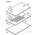
- An example of a microchemical chip 1 to which the present invention is applied is a rubber sheet between a metal substrate sheet 10 for a cover and a metal substrate sheet 30 for supporting a bottom surface as shown in FIG. 20 is the flexible one superimposed.
- a groove-like flow path 26 is formed through the front and back surfaces of the rubber sheet 20 to pressurize and flow a fluid sample, which is a liquid or gaseous specimen or reagent, to cause a chemical reaction.
- the flow path 26 extends from the flow sample injection sites 21a and 21b, which are the start point ends, and merges downstream, and branches into a tributary extending from there to the flow sample discharge site 22a and a main flow extending to the flow sample discharge sites 22b and 22c. Then, the main stream extends and branches to the flow sample discharge portions 22b and 22c which are the end points at the downstream end.
- the surfaces of the upper surface 24 and the lower surface 25 of the rubber sheet 20 are activated outside the region of the flow path 26.
- the fluid sample injection holes 11a and 11b are respectively provided at positions corresponding to the fluid sample injection sites 21a and 21b and the fluid sample discharge sites 22a, 22b, and 22c. And the fluid sample discharge holes 12a, 12b, and 12c are open.
- the lower surface 15 of the cover base sheet 10 facing the rubber sheet 20 has its surface activated outside the region of the flow sample injection holes 11a and 11b and the flow sample discharge holes 12a, 12b and 12c.
- the entire upper surface 34 of the base sheet 30 for supporting the bottom surface facing the rubber sheet 20 is activated.
- activated groups such as hydroxyl groups that are activated or inherently dehydrated to form ether bonds, which are strong covalent bonds, or silane A new covalent bond is generated through a plurality of functional groups in the molecule of the coupling agent, and both sheets are directly bonded chemically.
- the rubber sheet 20 may be made of any silicone rubber or non-silicone rubber.
- the rubber sheet 20 is mainly composed of peroxide-crosslinked silicone rubber, addition-crosslinked silicone rubber, silicone rubber exemplified by condensation-crosslinked silicone rubber, and a co-blend of these silicone rubber and olefin rubber. It is a silicone rubber elastic sheet produced by putting the illustrated three-dimensional silicone rubber or non-silicone rubber into a molding die or the like and then cross-linking as necessary. These rubber materials have an average molecular weight of 10,000 to 1,000,000.
- the peroxide-crosslinked silicone rubber as the material of the rubber sheet 20 is not particularly limited as long as it is synthesized using a silicone raw material compound that can be crosslinked with a peroxide-based crosslinking agent.
- a silicone raw material compound that can be crosslinked with a peroxide-based crosslinking agent.
- peroxide-based crosslinking agent examples include ketone peroxides, diacyl peroxides, hydroperoxides, dialkyl peroxides, peroxyketals, alkyl peresters, and percarbonates.
- ketone peroxide, peroxyketal, hydroperoxide, dialkyl peroxide, peroxycarbonate, peroxy ester benzoyl peroxide, dicumyl peroxide, dibenzoyl peroxide, t-butyl hydroperoxide, di-t-butyl Hydroperoxide, di (dicyclobenzoyl) peroxide, 2,5-dimethyl-2,5bis (t-butylperoxy) hexane, 2,5-dimethyl-2,5bis (t-butylperoxy) Hexyne, benzophenone, Mihiraaketon, dimethylaminobenzoic acid ethyl ester, benzoin ethyl ether.
- the amount of the peroxide-based crosslinking agent used is appropriately selected according to the type of silicone rubber obtained, the properties of the rubber sheet 20 molded with the silicone rubber, and the properties of the silane coupling agent used as necessary. However, 0.01 to 10 parts by mass, preferably 0.1 to 2 parts by mass is used with respect to 100 parts by mass of the silicone rubber. If it is less than this range, the crosslinking degree is too low to be used as silicone rubber. On the other hand, if the amount is larger than this range, the degree of crosslinking is too high and the elasticity of the silicone rubber is reduced.
- the addition-type silicone rubber as the material of the rubber sheet 20 includes vinylmethylsiloxane / polydimethylsiloxane copolymer, vinyl-terminated polydimethylsiloxane, vinyl-terminated diphenylsiloxane / polydimethylsiloxane copolymer, vinyl-terminated diethylsiloxane / polysiloxane synthesized in the presence of Pt catalyst.
- the processing conditions for producing the rubber sheet 20 from these compositions vary depending on the type and characteristics of the addition reaction, and therefore cannot be uniquely determined.
- the rubber sheet 20 is heated at 0 to 200 ° C. for 1 minute to 24 hours. It is. Thereby, an addition-type silicone rubber is obtained as the rubber sheet 20.
- the reaction time becomes longer.
- productivity faster than physical properties is required, the processing is performed at a high temperature for a short time.
- the machining temperature is set to a relatively high temperature within the above range in accordance with the desired machining time.
- Condensation type silicone rubber as the material of the rubber sheet 20 is made of silanol-terminated polydimethylsiloxane, silanol-terminated polydiphenylsiloxane, silanol-terminated polytrifluoromethylsiloxane, silanol-terminated diphenylsiloxane / dimethylsiloxane copolymer synthesized in the presence of a tin-based catalyst.
- the processing conditions for preparing the condensation-type silicone rubber from these compositions vary depending on the type and characteristics of the condensation reaction, and therefore cannot be uniquely determined. In general, heating is performed at 0 to 100 ° C. for 10 minutes to 24 hours. Is. Thereby, a condensation type silicone rubber is obtained as the rubber sheet 20. When the physical properties of the silicone rubber are better under low temperature processing conditions, the reaction time becomes longer. When productivity faster than physical properties is required, the processing is performed at a high temperature for a short time. When machining must be performed within a certain period of time depending on the production process and work environment, the machining temperature is set to a relatively high temperature within the above range in accordance with the desired machining time.
- the olefin rubber used in the co-blend of silicone rubber and olefin rubber of the rubber sheet 20 is 1,4-cis butadiene rubber, isoprene rubber, styrene / butadiene copolymer rubber, polybutene rubber, polyisobutylene rubber, Examples include ethylene / propylene rubber, ethylene-propylene-diene rubber, chlorinated ethylene propylene rubber, and chlorinated butyl rubber.
- Non-silicone rubber as the material of the rubber sheet 20 is natural rubber, 1,4-cis butadiene rubber, isoprene rubber, polychloroprene, styrene / butadiene copolymer rubber, hydrogenated styrene / butadiene copolymer rubber, acrylonitrile / butadiene copolymer.
- Rubber hydrogenated acrylonitrile / butadiene copolymer rubber, polybutene rubber, polyisobutylene rubber, ethylene / propylene rubber, ethylene-propylene-diene rubber, ethylene oxide-epichlorohydrin copolymer rubber, chlorinated polyethylene rubber, chlorosulfonated Polyethylene rubber, alkylated chlorosulfonated polyethylene rubber, chloroprene rubber, chlorinated acrylic rubber, brominated acrylic rubber, fluoro rubber, epichlorohydrin and its copolymer rubber, chlorinated ethylene propylene , Chlorinated butyl rubber, brominated butyl rubber, homopolymer rubbers such as tetrafluoroethylene, hexafluoropropylene, vinylidene fluoride and tetrafluoroethylene, and their binary and terpolymer rubbers, ethylene / tetrafluoroethylene
- a raw material rubber-like material composition exemplified by
- the material of the rubber sheet 20 is preferably silicone rubber.
- the flow path 26 of the rubber sheet 20 has a width of 0.5 ⁇ m to 5 mm, preferably 10 to 1000 ⁇ m, and its shape is not particularly limited, and may be a continuous line and / or a branched line, either a straight line or a curved line. A single or a plurality of them may be provided in parallel.
- the thickness of the rubber sheet 20 is preferably 5 to 100 ⁇ m. Since the flow path 26 is narrow and the thickness of the rubber sheet 20 is thin, the contact area between the specimen and reagent and the rubber sheet can be minimized, and the specimen and reagent due to leakage of the rubber component from the rubber sheet. Contamination and adsorption to rubber components can be prevented.
- the rubber sheet 20 has a non-reactive resin, for example, a fluororesin such as polytetrafluoroethylene resin, 2-methacryloyloxyethyl, so that at least the wall surface 27 of the flow path 26 does not contaminate or adsorb the specimen or reagent.
- a fluororesin such as polytetrafluoroethylene resin, 2-methacryloyloxyethyl
- a non-reactive resin for example, a fluororesin such as polytetrafluoroethylene resin, 2-methacryloyloxyethyl
- a phosphoric resin such as phosphorylcholine (MPC) polymer
- paraxylylene resin such as parylene
- a non-reactive inorganic substance such as titanium dioxide or silicon dioxide
- the base sheet 10/30 is made of ceramic, glass, or resin in addition to metal, and may be formed in a single plate or thin layer, or may be laminated.
- the substrate sheets 10 and 30 are relatively stable with respect to the specimen and the reagent, but it is preferable that the portion in contact with the specimen and the reagent is formed of resin, coated, or laminated.
- Metals constituting the base sheet 10/30 are gold, silver, copper, iron, cobalt, silicone, lead, manganese, tungsten, tantalum, platinum, cadmium, tin, palladium, nickel, chromium, titanium, zinc, aluminum, magnesium And the metals exemplified by (2), binary, ternary and multicomponent alloys of these metals.
- Ceramics constituting the base sheet 10/30 are silver, copper, iron, cobalt, silicone, lead, manganese, tungsten, tantalum, platinum, cadmium, tin, palladium, nickel, chromium, indium, titanium, zinc, calcium, barium. And oxides, nitrides, and carbides of metals such as aluminum, magnesium, sodium, and potassium, and simple substances or composites thereof.
- Examples of the glass forming the base sheet 10.30 include quartz, borosilicate glass, and alkali-free glass.
- the resin forming the base sheet 10/30 is polycarbonate resin, cycloolefin resin, acrylic resin, epoxy resin, polyethylene terephthalate resin, polybutene terephthalate resin, cellulose and its derivatives, hydroxyethyl cellulose, starch, cellulose diacetate, surface ken Vinyl acetate resin, low density polyethylene, high density polyethylene, i-polypropylene, petroleum resin, polystyrene, s-polystyrene, chroman indene resin, terpene resin, styrene divinylbenzene copolymer, ABS resin, polymethyl acrylate, Polyethyl acrylate, polyacrylonitrile, polymethyl methacrylate, polyethyl methacrylate, polycyanoacrylate, polyvinyl acetate, polyvinyl alcohol, polyvinyl formal, Livinyl acetal, polyvinyl chloride, vinyl chloride / vinyl acetate copolymer, vinyl chlor
- the activation is performed by performing activation treatment of corona discharge treatment, plasma treatment, and ultraviolet irradiation treatment.
- the metal, ceramic or glass base sheet 10/30 and the silicone rubber rubber sheet 20 are firmly joined by an ether bond formed by dehydration of active groups such as hydroxyl groups generated by activation treatment. is doing.
- active groups such as hydroxyl groups generated by activation treatment. is doing.
- the active group such as a hydroxyl group is sufficiently exposed in advance so that an ether bond can be formed only by laminating the two, the activation treatment may not be performed.
- a rubber sheet 20 made of silicone rubber or non-silicone rubber and a base sheet 10/30 made of metal, ceramics, glass, or resin may be corona discharge treatment, plasma treatment, ultraviolet ray at at least one of the joining surfaces thereof.
- Silane which has been activated by irradiation treatment and has an amino group and / or a hydrolyzable alkoxy group equivalent group capable of reacting with an alkoxy group having 1 to 4 carbon atoms or a hydroxyl group in the same manner to form an ether group It joins by this chemical bond through a coupling agent.
- amino group-free silane coupling agent having an alkoxy group examples include commercially available silane coupling agents, specifically vinyltrimethoxysilane (KBM-1003) and vinyltriethoxysilane (KBE-1003). Vinyl group and alkoxy group-containing silane coupling agent; 2- (3,4-epoxycyclohexyl) ethyltrimethoxysilane (KBM-303), 3-glycidoxypropylmethyldimethoxysilane (KBM-402), 3-glycid Epoxy groups and alkoxy groups exemplified by xylpropyltrimethoxysilane (KBM-403), 3-glycidoxypropylmethyldiethoxysilane (KBE-402), 3-glycidoxypropyltriethoxysilane (KBE-403) Containing silane coupling agent; p-s A styryl group and alkoxy group-containing silane coupling agent exemplified by riltrimethoxysi
- the amino group-free silane coupling agent having an alkoxy group is a hydrosilyl group (SiH group) -containing alkoxysilyl compound, for example, (CH 3 O) 3 SiCH 2 CH 2 CH 2 Si (CH 3 ) 2 OSi (CH 3 ) 2 H, (C 2 H 5 O) 3 SiCH 2 CH 2 CH 2 Si (CH 3 ) 2 OSi (CH 3 ) 2 H, (CH 3 O) 3 SiCH 2 CH 2 CH 2 Si (OCH 3 ) 2 OSi (OCH 3 ) 3 , (C 2 H 5 O) 3 SiCH 2 CH 2 CH 2 Si (OCH 3 ) 2 OSi (OCH 3 ) 3 , (C 2 H 5 O) 3 SiCH 2 CH 2 CH 2 Si (CH 3 ) 2 H, (CH 3 O) 3 SiCH 2 CH 2 CH 2 Si (CH 3 ) 2 H, (iC 3 H 7 O) 3 SiCH 2 CH 2 CH 2 Si (CH 3 ) H 2 , (nC 3 H 7 O) 3 Si
- vinyl groups and SiH groups may be promoted with a metal catalyst such as a platinum-containing compound to join the base sheet and the rubber sheet.
- silane coupling agent having an alkoxy group a commercially available silane coupling agent, specifically N-2- (aminoethyl) -3-aminopropylmethyldimethoxysilane (KBM-602), N- 2- (aminoethyl) -3-aminopropyltrimethoxysilane (KBM-603), N-2- (aminoethyl) -3-aminopropyltriethoxysilane (KBE-603), 3-aminopropyltrimethoxysilane ( KBM-903), 3-aminopropyltriethoxysilane (KBE-903), 3-triethoxysilyl-N- (1,3-dimethyl-butylidene) propylamine (KBE-9103), N-phenyl-3-amino Propyltrimethoxysilane (KBM-573), N- (vinylbenzyl) -2-amino An amino group
- the base sheets 10 and 30 are made of metal, ceramics, or glass and the rubber sheet 20 is made of silicone rubber, it is preferable that the two are directly joined by an ether bond.
- the base sheet 10/30 and the rubber sheet 20 are subjected to corona discharge treatment to generate an active group such as a hydroxyl group on the surface, and the base sheet 10/30 and the rubber are pressed by pressure bonding or pressure reduction.
- the sheet 20 is dehydrated to form an ether bond.
- both of them are via an amino group-free silane coupling agent having an alkoxy group. Bonding is preferably performed by a covalent bond of an oxygen-carbon bond, a carbon-carbon bond, and an oxygen-silicon bond.
- the base sheet 10/30 and the rubber sheet 20 are subjected to corona discharge treatment to generate an active group such as a hydroxyl group on the surface thereof, an alkoxy group or an alkoxy group equivalent group, and an unsaturated group if necessary,
- an active group such as a hydroxyl group on the surface thereof, an alkoxy group or an alkoxy group equivalent group, and an unsaturated group if necessary
- a silane coupling agent containing an epoxy group, a ureido group, a sulfide group, an isocyanate group and not containing an amino group at the time of pressure bonding under normal pressure, pressure or reduced pressure at normal temperature or by heating. These covalent bonds are formed.
- both are oxygen-containing via an amino group-containing silane coupling agent having an alkoxy group.
- Bonding is preferably performed by a chemical bond between a covalent bond of a silicon bond and a hydrogen bond of a hydroxyl group-amino group, or a covalent bond such as an amide bond or an imino bond with a newly formed carboxyl group or carbonyl group.
- the base sheet 10/30 and the rubber sheet 20 are subjected to corona discharge treatment to produce an active group such as a hydroxyl group on the surface thereof, and a silane cup containing an alkoxy group or an alkoxy group equivalent group and an amino group
- an active group such as a hydroxyl group on the surface thereof
- the amino group of the silane coupling agent is easily adsorbed to the resin, and when the resin is a polycarbonate resin, a cycloolefin resin, a polyethylene terephthalate resin, an acrylic resin, or an epoxy resin, the reaction proceeds particularly quickly and quickly. Easy to join firmly.
- polycarbonate resins and cycloolefin resins are particularly excellent in water resistance.
- This is facilitated by removing the gaseous medium at the contact interface or by heating the contact interface by applying stress (load), for example 10-200 kgf, to the contact interface.
- stress for example 10-200 kgf
- pressure is uniformly applied to the entire bonding surface between the hydroxyl group of the base sheet 10 or 30 and the rubber sheet 20 under reduced pressure or pressurized conditions. If it is out of the above range, the pressure may not be applied uniformly.
- such a microchemical chip 1 is manufactured as follows.
- the silicone rubber sheet 20 is cut into a rectangular parallelepiped.
- the rubber sheet 20 is cut out and penetrated by laser processing, and the fine flow path 26 is attached to the rubber sheet 20.
- the flow path 26 is formed by laser processing, extending from the flow sample injection sites 21a and 21b at the start end, joining downstream, and extending from there to the flow sample discharge site 22a, and a main flow extending to the flow sample discharge sites 22b and 22c.
- the main stream is formed in a shape that extends downstream and branches to the end-end flow sample discharge sites 22b and 22c.
- the cover metal base sheet 10 having the same size as the rubber sheet 20 is cut out.
- the flow sample injection holes 11a and 11b and the flow sample discharge holes 12a, 12b, and 12c are respectively provided at positions corresponding to the flow sample injection portions 21a and 21b and the flow sample discharge portions 22a, 22b, and 22c. Are drilled or punched with a drill.
- the metal base sheet 30 for supporting the bottom surface is cut out to the same size as the rubber sheet 20.
- the base sheet 10.30 and the rubber sheet 20 are washed with alcohol and water.
- the lower surface 15 of the base material sheet 10 the upper surface 34 of the base material sheet 30, and the upper and lower surfaces 24 and 25 of the rubber sheet 20 are subjected to corona discharge treatment, new hydroxyl groups are generated on the surfaces.
- the rubber sheet 20 is sandwiched between the base material sheets 10 and 30, and the pressure is reduced, for example, 10 torr or less.
- the pressure is reduced, for example, 10 torr or less.
- the hydroxyl groups of the base sheets 10 and 30 and the hydroxyl groups of the rubber sheet 20 are dehydrated to form an ether bond.
- a microchemical chip 1 is obtained.
- an active group that is a hydroxyl group is generated on the surface of the organic or inorganic base sheet 10 or 30 or the rubber sheet 20, or a carboxyl group is further formed on the surface of the organic base sheet 10 or 30 or the rubber sheet 20.
- An active group exemplified by a group or a carbonyl group may be formed.
- the base sheet 10/30 and the rubber sheet 20 may or may not have a hydroxyl group from the beginning, but a corona discharge, an atmospheric pressure plasma treatment, or an ultraviolet irradiation treatment may be applied even if these surfaces do not have a hydroxyl group. Thus, hydroxyl groups are efficiently generated there.
- the optimum processing conditions vary depending on the material type and history of the base material surface of the base material sheet 10/30 or the rubber sheet 20, but the processing may be continued until a surface tension of 55 kJ / m or more is obtained on the surface. is important. Thereby, sufficient adhesive strength is obtained.
- the corona discharge treatment of the base sheet 10.30 or the rubber sheet 20 is performed using, for example, a power source: AC100V, output using a corona surface reformer (for example, Corona Master manufactured by Shinko Electric Instrumentation Co., Ltd.). Voltage: 0 to 20 kV, oscillation frequency: 0 to 40 kHz, 0.1 second to 60 seconds, temperature 0 to 60 ° C.
- a power source AC100V
- a corona surface reformer for example, Corona Master manufactured by Shinko Electric Instrumentation Co., Ltd.
- the atmospheric pressure plasma treatment of the base sheet 10 or 30 or the rubber sheet 20 is performed using an atmospheric pressure plasma generator (for example, Matsushita Electric Works Co., Ltd .: trade name Aiplasma), for example, with a plasma treatment speed of 10 to 100 mm / s, Power source: 200 or 220 V AC (30 A), compressed air: 0.5 MPa (1 NL / min), 10 kHz / 300 W to 5 GHz, power: 100 W to 400 W, irradiation time: 0.1 second to 60 seconds.
- an atmospheric pressure plasma generator for example, Matsushita Electric Works Co., Ltd .: trade name Aiplasma
- UV-LED ultraviolet-light emitting diode
- UV-LED irradiation device for example, UV-LED irradiation device manufactured by OMRON Corporation: trade name ZUV-C30H.
- UV-LED ultraviolet-light emitting diode
- it is performed under the conditions of wavelength: 200 to 400 nm, power source: 100 V AC, light source peak illuminance: 400 to 3000 mW / cm 2 , irradiation time: 1 to 60 seconds.
- the surfaces 15 and 34 to be joined of the base sheet 10 and 30 are immersed or sprayed with a silane coupling agent solution that is a molecular adhesive, and then the base sheet 10 and 30
- the rubber sheet 20 may be contacted.
- a silane coupling agent solution that is a molecular adhesive
- the base sheet 10.30 with the silane coupling agent is dried while heating by placing it in an oven, blowing warm air with a dryer, or irradiating high frequency. Heating and drying are performed at a temperature range of 50 to 250 ° C. for 1 to 60 minutes. If it is less than 50 degreeC, the reaction time of the hydroxyl group produced
- the immersion and drying may be repeated about 1 to 5 times. As a result, it is possible to sufficiently advance the reaction by shortening the time of dipping and drying per time and increasing the number of reactions.
- the microchemical chip 1 is used as follows, for example, with reference to FIG.
- the microchemical chip 1 is mounted on the main body of a microreactor (not shown) as a reaction device.
- a pressurizer that is connected to a hole for injecting a fluid sample, injects the fluid sample, pressurizes it, and then flows it into the flow path, a syringe (non-injection) is provided in each of the fluid sample injection holes 11a and 11b of the base sheet 10 for cover.
- the fluid sample which is a liquid specimen and a liquid reagent, is separately fed from each syringe through the fluid sample injection sites 21a and 21b while being pressurized to 3 MPa or less.
- the reaction apparatus of the present invention comprises at least a microchemical chip 1, an apparatus main body on which the microchemical chip 1 is mounted, and a pressurizer that pressurizes after injecting a fluid sample into the microchemical chip 1.
- the pressurizer includes an injector such as a syringe connected to a hole for injecting a fluid sample, and a fluid machine such as a pump for feeding the fluid sample. With this pressurizer, a fluid sample can be injected and poured into the channel 26.
- the flow rate is preferably 0.1 to 500 ⁇ l / min.
- the reaction apparatus may have a heating mechanism such as a heater or a cooling mechanism in contact or non-contact with the top and bottom of the microchemical chip 1.
- the microchemical chip 1 includes a metal substrate sheet 10 for a cover, a first rubber sheet 20, a metal substrate sheet 30 for an insole, a second rubber sheet 40, and a metal substrate sheet 50 for supporting the bottom surface in this order. It is a superposition.
- the rubber sheets 20 and 40 are formed with flow paths 26 and 46 penetrating the front and back.
- the flow path 26 extends from the flow sample injection sites 21a and 21b, which are the starting end of the rubber sheet 20, and merges downstream, and then flows into a tributary that extends to the flow sample discharge site 22a and a main flow that extends to the flow sample transfer site 23.
- the insole metal base sheet 30 has a fluid sample transport hole 33 at a position corresponding to the fluid sample transport site 23.
- a check valve may be provided in the flow sample transfer hole 33.
- the second rubber sheet 40 is provided with a flow sample transfer portion 43 at a position corresponding to the flow sample transfer hole 33, and extends from the flow sample injection portion 41 a, which is another starting point end, and joins it downstream.
- a flow sample injection hole 51a and flow sample discharge holes 52a and 52b are formed in the metal substrate sheet 50 for supporting the bottom surface at positions corresponding to the flow sample injection portion 41a and the flow sample discharge portions 42a and 42b.
- the base material sheets 10, 20, and 30 and the rubber sheets 20, 40 are directly bonded via an ether bond as in FIG.
- the base material sheets 10, 20, 30 and the rubber sheets 20, 40 may have the above-described materials and shapes, and may be joined via a silane coupling agent.
- the microchemical chip 1 is used by feeding a fluid sample under pressure as in the case of FIG.
- the microchemical chip 1 can prevent unintentional mixing when injecting fluid samples having different molecular weights, composition components, and composition properties in the flow paths 26 and 46 of the plurality of rubber sheets 20 and 40, respectively.
- the sample may be appropriately separated when the fluid sample reacts in the channels 26 and 46 and the molecular weight of the target substance in the fluid sample changes or the specific gravity of the fluid sample changes.
- the microchemical chip 1 is composed of the base material sheets 10 and 30 and the rubber sheet 20 shown in FIG. 1, and the outermost base material sheets 10 and 30 together with the rubber sheet 20 are bent by two resin plates or metal plates. It is sandwiched between rigid holders 60a and 60b. These are screwed and fixed. At the positions corresponding to the flow sample injection holes 11a, 11b and the flow sample discharge holes 12a, 12b, 12c of the base sheet 10, 30 to the holders 60a, 60b, the injection guide holes 61a, 61b and the discharge guide holes 62a, 62b, 62c is open.
- the microchemical chip 1 is used by applying a fluid sample to the flow channel 26 under pressure as in the case of FIG.
- the holders 60a and 60b are tightened to such a degree that the fluid sample flows through the flow path 26 while correcting the flexible base sheets 10 and 30 and the rubber sheet 20 so as not to bend.
- the microchemical chip 1 may have a base sheet 10, 30, 50 and a rubber sheet 20, 40 shown in FIG.
- the microchemical chip 1 in FIGS. 1 and 2 may be joined by inserting a heater between the base sheet 10/30 and the rubber sheet 20, and the heater is arranged on the holder in FIG. (Not shown).
- the microchemical chip 1 has a specimen / reagent / reaction product in any one of the fluid sample injection sites 21a and 21b, the fluid sample discharge sites 22a, 22b, and 22c, the fluid sample injection site, and the fluid sample discharge sites 41a, 42a, and 42b.
- a sensor such as an electrode for detecting the above may be wired.
- Example 1 The microchemical chip 1 shown in FIG. 1 was produced with the cycloolefin resin substrate sheet 10/30 and the silicone rubber sheet 20.
- the cycloolefin resin base sheet 10.30 is formed of ZEONOR (registered trademark, manufactured by Nippon Zeon Co., Ltd.), which is a cycloolefin resin, and has a thickness of 2 mm and a size of 30 ⁇ 40 mm.
- the silicone rubber sheet 20 is formed of SH-851-U (trade name, manufactured by Toray Dow Corning Co., Ltd.), which is the same shape as the cycloolefin resin substrate sheet 10/30, and is polydimethylsiloxane, and has a thickness of 50 ⁇ m. . As shown in FIG.
- the fluid sample injection holes 11a and 11b and the fluid sample discharge holes 12a and 12c were drilled in the cover base sheet 10 with a drill.
- cover base sheet 10 and the bottom support base sheet 30 are washed with ethanol and water, the surface is activated by corona discharge three times at a gap length of 1 mm, a voltage of 13.5 kv, and 70 mm / sec. Processed.
- Substrate sheets 10 and 30 are immersed in an ethanol solution of 0.1% by weight of 3- (2-aminoethylamino) propyltrimethoxysilane, which is a silane coupling agent, washed with ion-exchanged water, and air gun It was air-dried, heated at 80 ° C.
- Example 2 A microchemical chip 1 shown in FIG. 1 was produced with stainless base sheets 10 and 30 having a thickness of 30 mm in length and width of 2 mm, and a silicone rubber sheet 20 having the same shape and thickness of 50 ⁇ m.
- a flow path 26 having fluid sample injection sites 21a, 21b, and 21b and fluid sample discharge sites 22a, 22b, and 22c was formed in the silicone rubber sheet 20 with a laser processing machine.
- the fluid sample injection holes 11a and 11b and the fluid sample discharge holes 12a, 12b, and 12c were drilled in the base sheet 10 with a drill.
- the base sheet 10.30 was washed with ethanol and water.
- Example 3 Production of microchemical chip
- the microchemical chip 1 shown in FIG. 4 was produced with the cycloolefin resin substrate sheets 10 and 30 and the silicone rubber sheet 20.
- the cycloolefin resin substrate sheet 10/30 is formed of ZEONOR (Nippon Zeon Co., Ltd., registered trademark), which is a cycloolefin resin, and the cycloolefin resin substrate sheet 10 has a thickness of 2 mm. The thickness is 188 ⁇ m and the size is 30 ⁇ 40 mm.
- the silicone rubber sheet 20 is formed of SH-851-U (trade name, manufactured by Toray Dow Corning Co., Ltd.), which is the same shape as the cycloolefin resin base sheet 10, 30 and is polydimethylsiloxane, and has a thickness of 500 ⁇ m. .
- SH-851-U trade name, manufactured by Toray Dow Corning Co., Ltd.
- a flow path 26 branched in a groove shape having a width of 500 ⁇ m having flow sample injection portions 21a, 21b, 21c and a flow sample discharge portion 22a having a diameter of 1 mm as shown in FIG. It was formed with a model Laserpro SPIRIT (manufactured by Comnet Co., Ltd., processing conditions speed10, power30, PPI400).
- the fluid sample injection holes 11a, 11b, and 11c and the fluid sample discharge holes 12a were drilled in the cover base sheet 10 with a drill.
- the surface is activated by corona discharge three times at a gap length of 1 mm, a voltage of 13.5 kv, and 70 mm / sec. Processed.
- Substrate sheets 10 and 30 were immersed in an ethanol solution of 0.1% by weight of 3- (2-aminoethylamino) propyltrimethoxysilane (AEAPS) as a silane coupling agent, and then air-dried with an air gun at 80 ° C.
- AEAPS 2-aminoethylamino propyltrimethoxysilane
- Liquid C Formaldehyde liquid (Wako Pure Chemical Industries, Ltd.) 35.0-38.0% (3) Reaction in microchemical chip After the prepared microchemical chip was preheated on a metal plate heated to 90 ° C. for 5 minutes, liquid A and liquid B prepared from fluid sample injection holes 11a, 11b, and 11c by a pressurizer. C liquid was introduced at a flow rate of 3 ⁇ l / min, 3 ⁇ l / min, and 1 ⁇ l / min, respectively. After standing for a certain period of time and visually checking the discharged liquid discharged from the fluid sample discharge hole 12a, the color change to reddish brown was confirmed, and mixing and reaction of the liquid in the microchemical chip were confirmed.
- the microchemical chip of the present invention analyzes the biological components of patients in emergency medical settings where it is necessary to quickly know the analysis results, and extracts DNA from remains such as traces of blood stains, body fluids, hair, and biological tissue cells in crime scenes. DNA analysis to extract and increase the DNA, DNA analysis by electrophoresis, physical properties and efficacy evaluation of various drug candidates for new drug search, diagnosis for tailor-made medicine, peptides, DNA and functions It is used for the synthesis of low-molecular-weight small molecules.
- the microchemical chip can easily form a freely shaped flow path, it can be used for custom-made medical care and identification of DNA analysis of various animals and plants.
- the microchemical chip obtained by the method for producing the microchemical chip of the present invention is attached to the analysis device or microreactor to perform a medical examination or treatment, or a criminal investigation field using a biological sample. It can be used for various analyzes in Japan, microorganism search using an underwater robot in remote areas such as the ocean and lakes, and various synthesis in drug development.
- the reaction apparatus of the present invention is an apparatus for performing an analysis reaction or a synthesis reaction of a very small amount of specimen and / or reagent, and can be specifically used as an analysis apparatus or a microreactor.
- 1 is a microchemical chip
- 10 is a base sheet
- 11a and 11b are fluid sample injection holes
- 12a, 12b and 12c are fluid sample discharge holes
- 15 is a bottom surface
- 20 is a rubber sheet
- 21a and 21b are fluid sample injection sites
- 22a, 22b and 22c are fluid sample discharge sites
- 23 is a fluid sample transport site
- 24 is a top surface
- 25 is a bottom surface
- 26 is a flow path
- 27 is a wall surface
- 30 is a base sheet
- 33 is a fluid sample transport hole
- 34 is Upper surface
- 40 is a rubber sheet
- 41a is a flow sample injection site
- 42a and 42b are flow sample discharge sites
- 43 is a flow sample transfer site
- 50 is a base sheet
- 51a is a flow sample injection hole
- 52a and 52b are flow sample discharges
- Holes 60a and 60b are holders
- 61a and 61b are injection guide holes
Landscapes
- Health & Medical Sciences (AREA)
- Chemical & Material Sciences (AREA)
- Immunology (AREA)
- Life Sciences & Earth Sciences (AREA)
- Hematology (AREA)
- Engineering & Computer Science (AREA)
- Chemical Kinetics & Catalysis (AREA)
- Analytical Chemistry (AREA)
- General Health & Medical Sciences (AREA)
- Biomedical Technology (AREA)
- Molecular Biology (AREA)
- Urology & Nephrology (AREA)
- Dispersion Chemistry (AREA)
- Organic Chemistry (AREA)
- Clinical Laboratory Science (AREA)
- Pathology (AREA)
- Biochemistry (AREA)
- Biotechnology (AREA)
- General Physics & Mathematics (AREA)
- Medicinal Chemistry (AREA)
- Food Science & Technology (AREA)
- Microbiology (AREA)
- Cell Biology (AREA)
- Physics & Mathematics (AREA)
- Physical Or Chemical Processes And Apparatus (AREA)
- Automatic Analysis And Handling Materials Therefor (AREA)
- Micromachines (AREA)
- Laminated Bodies (AREA)
Abstract
Description
アミノプロピル末端ポリジメチルシロキサン、アミノプロピルメチルシロキサン/ジメチルシロキサンコポリマー、アミノエチルアミノイソブチルメチルシロキサン/ジメチルシロキサンコポリマー、アミノエチルアミノプロピルメトキシシロキサン/ジメチルシロキサンコポリマー、ジメチルアミノ末端ポリジメチルシロキサンで例示されるアミノ基含有ポリシロキサンと、エポキシプロピル末端ポリジメチルシロキサン、(エポキシシクロヘキシルエチル)メチルシロキサン/ジメチルシロキサンコポリマーで例示されるエポキシ基含有ポリシロキサン、琥珀酸無水物末端ポリジメチルシロキサンで例示される酸無水物基含有ポリシロキサン及びトルイルジイソシアナート、1,6-ヘキサメチレンジイソシアナートなどのイソシアナート基含有化合物との組成物から得られるものである。
これらのシラノール基末端ポリシロキサンと、テトラアセトキシシラン、トリアセトキシメチルシラン、ジt-ブトキシジアセトキシシラン、ビニルトリアセトキシシラン、テトラエトキシシラン、トリエノキシメチルシラン、ビス(トリエトキシシリル)エタン、テトラ-n-プロポキシシラン、ビニルトリメトキシシラン、メチルトリス(メチルエチルケトキシム)シラン、ビニルトリス(メチルエチルケトキシイミノ)シラン、ビニルトリイソプロペノイキシシラン、トリアセトキシメチルシラン、トリ(エチルメチル)オキシムメチルシラン、ビス(N-メチルベンゾアミド)エトキシメチルシラン、トリス(シクロヘキシルアミノ)メチルシラン、トリアセトアミドメチルシラン、トリジメチルアミノメチルシランで例示される架橋剤との組成物、
これらのシラノール基末端ポリシロキサンと、クロル末端ポリジメチルシロキサン、ジアセトキシメチル末端ポリジメチルシロキサン、末端ポリシロキサンで例示される末端ブロックポリシロキサンの組成物から得られるものである。
(CH3O)3SiCH2CH2CH2Si(CH3)2OSi(CH3)2H、
(C2H5O)3SiCH2CH2CH2Si(CH3)2OSi(CH3)2H、
(CH3O)3SiCH2CH2CH2Si(OCH3)2OSi(OCH3)3、
(C2H5O)3SiCH2CH2CH2Si(OCH3)2OSi(OCH3)3、
(C2H5O)3SiCH2CH2CH2Si(CH3)2H、
(CH3O)3SiCH2CH2CH2Si(CH3)2H、
(i-C3H7O)3SiCH2CH2CH2Si(CH3)H2、
(n-C3H7O)3SiCH2CH2CH2Si(CH3)2OSi(CH3)2CH2CH2Si(CH3)2Si(CH3)2H、
(n-C4H9O)3SiCH2CH2CH2Si(CH3)2OSi(CH3)2H、
(t-C4H9O)3SiCH2CH2CH2Si(CH3)2OSi(CH3)2H、
(C2H5O)2CH3SiCH2CH2CH2Si(CH3)2OSi(CH3)2H、
(CH3O)2CH3SiCH2CH2CH2Si(CH3)2OSi(CH3)2CH2CH2Si(CH3)2Si(CH3)2H、
CH3O(CH3)2SiCH2CH2CH2Si(CH3)2OSi(CH3)2H、
(C2H5O)3SiCH2CH2CH2Si(CH3)2OSi(CH3)2H、
(n-C3H7)3SiCH2CH2CH2Si(CH3)2OSi(CH3)2H、
(i-C3H7O)3SiCH2CH2CH2Si(CH3)2OSi(CH3)2H、
(n-C4H9)3SiCH2CH2CH2Si(CH3)2OSi(CH3)2H、
(t-C4H9O)3SiCH2CH2CH2Si(CH3)2OSi(CH3)2H、
(C2H5O)3SiCH2CH2Si(CH3)2OSi(CH3)2H、
(C2H5O)3SiCH2CH2CH2CH2Si(CH3)2OSi(CH3)2H、
(C2H5O)3SiCH2CH2CH2CH2CH2CH2Si(CH3)2OSi(CH3)2H、
(C2H5O)3SiCH2CH2CH2CH2CH2CH2CH2CH2CH2CH2Si(CH3)2OSi(CH3)2H、
(CH3O)3SiCH2C6H4CH2CH2Si(CH3)2C6H4Si(CH3)2H、
(CH3O)2CH3SiCH2C6H4CH2CH2Si(CH3)2C6H4Si(CH3)2H、
CH3O(CH3)2SiCH2C6H4CH2CH2Si(CH3)2C6H4Si(CH3)2H、
(C2H5O)3SiCH2C6H4CH2CH2Si(CH3)2C6H4Si(CH3)2H、
(C2H5O)3SiCH2CH2CH2Si(CH3)2C6H4OC6H4Si(CH3)2H、
(C2H5O)3SiCH2CH2CH2Si(CH3)2C2H4Si(CH3)2H、
(C2H5O)3SiCH2CH2CH2Si(CH3)2O[Si(CH3)2O]p1Si(CH3)2H、
C2H5O(CH3)2SiCH2CH2CH2Si(CH3)2O[Si(CH3)2O]p2Si(C2H5)2H、
(C2H5O)2CH3SiCH2CH2CH2Si(CH3)2O[Si(CH3)2O]p3Si(CH3)2H、
(CH3)3SiOSiH(CH3)O[SiH(CH3)O]p4Si(CH3)3、
(CH3)3SiO[(C2H5OSi(CH3)CH2CH2CH2)SiCH3]O[SiH(CH3)O]p5Si(CH3)3、
(CH3)3SiO[(C2H5OSiOCH3CH2CH2CH2)SiCH3]O[SiH(CH3)O]p6Si(CH3)3、
(CH3)3SiO[(C2H5OSi(CH3)CH2CH2CH2)SiCH3]O[SiH(CH3)O]p7Si(CH3)3、
(CH3)3SiO[(Si(OC2H5)2CH2CH2CH2)SiCH3]O[SiH(CH3)O]p8Si(CH3)3、
(CH3)3SiOSi(OC2H5)2O[SiH(CH3)O]p9[Si(CH3)2O]q1Si(CH3)3、
(CH3)3SiO[(C2H5Osi(CH3)CH2CH2CH2CH2CH2CH2)Si(CH3)O][SiH(CH3)O]p10[Si(CH3)2O]q2Si(CH3)3、
(CH3)3SiO[(Si(OCH3)3CH2CH2CH2CH2CH2CH2)Si(CH3)O][SiH(CH3)O]p11[Si(CH3)2O]q3Si(CH3)3、
(CH3)3SiOSi(OC2H5)2O[SiH(C2H5)O]p12Si(CH3)3、
(CH3)3SiO[(Si(OC2H5)2CH2CH2CH2CH2CH2CH2)Si(C2H5)]O[SiH(C2H5)O]p13Si(CH3)3、
(CH3)3SiO[(C2H5OSi(CH3)CH2CH2CH2CH2CH2CH2)Si(C2H5)]O[SiH(C2H5)O]p14Si(CH3)3、
C2H5OSi(CH3)2CH2CH2CH2CH2CH2CH2(CH3)2SiO[HSi(CH3)2OSiC6H5O]p15Si(CH3)2H、
Si(OCH3)3CH2CH2CH2CH2CH2CH2(CH3)2SiO[HSi(CH3)2OSiC6H5O]p16Si(CH3)2H、
H(CH3)2SiO[(C2H5OSi(CH3)2CH2CH2CH2)Si(CH3)O][HSiCH3O]p17Si(CH3)2H、
H(CH3)2SiO[(C2H5OSi(CH3)2CH2CH2CH2CH2)Si(CH3)O][HSiCH3O]p18Si(CH3)2H、
H(CH3)2SiO[(C2H5OSi(CH3)2CH2CH2CH2CH2CH2CH2)Si(CH3)O][HSiCH3O]p19Si(CH3)2H、
H(CH3)2SiO[(C2H5OSi(CH3)2CH2CH2CH2CH2CH2CH2CH2CH2)Si(CH3)O][HSiCH3O]p20Si(CH3)2H、
H(CH3)2SiO[(C2H5OSi(CH3)2CH2CH2CH2CH2CH2CH2CH2CH2CH2CH2)Si(CH3)O][HSiCH3O]p21Si(CH3)2H、
H(CH3)2SiO[(Si(OCH3)3CH2CH2C6H4CH2CH2)Si(CH3)O][HSiCH3O]p22Si(CH3)2H、
H(CH3)2SiO[(Si(OCH3)3CH2C6H4CH2CH2CH2)Si(CH3)O][HSiCH3O]p23Si(CH3)2H、
H(CH3)2SiO[(Si(OCH3)3CH2C6H4CH2CH2)Si(CH3)O][HSiCH3O]p24Si(CH3)2H、
H(CH3)2SiO[(Si(OCH3)3C6H4CH2CH2)Si(CH3)O][HSiCH3O]p25Si(CH3)2H、
H(CH3)2SiO[(Si(OCH3)3CH2CH2CH2)Si(CH3)O][HSiCH3O]p26Si(CH3)2H、
H(CH3)2SiO[(Si(OCH3)3CH2CH2CH2CH2)Si(CH3)O][HSiCH3O]p27Si(CH3)2H、
H(CH3)2SiO[(Si(OCH3)3CH2CH2CH2CH2CH2CH2)Si(CH3)O][HSiCH3O]p28Si(CH3)2H、
H(CH3)2SiO[(Si(OCH3)3CH2CH2CH2CH2CH2CH2CH2CH2)Si(CH3)O][HSiCH3O]p29Si(CH3)2H、
H(CH3)2SiO[(Si(OCH3)3CH2CH2CH2CH2CH2CH2CH2CH2CH2CH2)Si(CH3)O][HSiCH3O]p30Si(CH3)2H、
H(CH3)2SiO[(Si(OCH3)3CH2CH2C6H4CH2CH2)Si(CH3)O][HSiCH3O]p31Si(CH3)2H、
H(CH3)2SiO[(Si(OCH3)3CH2C6H4CH2CH2CH2)Si(CH3)O][HSiCH3O]p32Si(CH3)2H、
H(CH3)2SiO[(Si(OCH3)3CH2C6H4CH2CH2)Si(CH3)O][HSiCH3O]p33Si(CH3)2H、
H(CH3)2SiO[(Si(OCH3)3C6H4CH2CH2)Si(CH3)O][HSiCH3O]p34Si(CH3)2H、
H(CH3)2SiO[(Si(OCH3)3CH2CH2C6H4CH2CH2)Si(CH3)O][HSiCH3O]p35Si(CH3)2H、
H(CH3)2SiO[(CH3O)Si(CH3)CH2CH2CH2CH2CH2CH2Si(CH3)2OSiC6H5O]p36[HSi(CH3)2OSiC6H5O]q4Si(CH3)2H、
H(CH3)2SiO[Si(OCH3)2CH2CH2CH2CH2CH2CH2Si(CH3)2OSiC6H5O]p37[HSi(CH3)2OSiC6H5O]q5Si(CH3)2H、
C2H5O(CH3)2SiO[SiH(CH3)O]p38[SiCH3(C6H5)O]q6Si(CH3)2H、
Si(OC2H5)3CH2CH2CH2CH2CH2CH2(CH3)2SiO[SiH(CH3)O]p39[SiCH3(C6H5)O]q7Si(CH3)2H、
C2H5OSi(CH3)2CH2CH2CH2CH2CH2CH2(CH3)2SiO[SiH(CH3)O]p40[SiCH3(C6H5)O]q8Si(CH3)2H、
H(CH3)2SiO(C2H5O)Si(CH3)O[SiH(CH3)O]p41[SiCH3(C6H5)O]q9Si(CH3)2H、
H(CH3)2SiO[Si(OC2H5)3CH2CH2CH2Si(CH3)]O[SiH(CH3)O]p42[SiCH3(C6H5)O]q10Si(CH3)2H
であってもよい。これらの基中、p1~p42及びq1~q10は1~100までの数である。一つの分子に、ヒドロシリル基を、1~99個有していることが好ましい。
(C2H5O)3SiCH2CH=CH2、
(CH3O)3SiCH2CH2CH=CH2、
(C2H5O)3SiCH2CH2CH=CH2、
(CH3O)3SiCH2CH2CH2CH2CH=CH2、
(C2H5O)3SiCH2CH2CH2CH2CH=CH2、
(C2H5O)3SiCH2CH2CH2CH2CH2CH2CH=CH2、
(CH3O)3SiCH2(CH2)7CH=CH2、
(C2H5O)2Si(CH=CH2)OSi(OC2H5)CH=CH2、
(CH3O)3SiCH2CH2C6H4CH=CH2、
(CH3O)2Si(CH=CH2)O[SiOCH3(CH=CH2)O]t1Si(OCH3)2CH=CH2、
(C2H5O)2Si(CH=CH2)O[SiOC2H5(CH=CH2)O]t2Si(OC2H5)3、
(C2H5O)3SiCH2CH2CH2Si(CH3)2OSi(CH3)2CH2CH2[Si(CH3)2O]t3CH=CH2、
(CH3O)3SiCH2CH2CH2Si(CH3)2OSi(CH3)2CH2CH2[Si(CH3)2O]t4CH=CH2、
CH3O(CH3)2SiCH2CH2CH2Si(CH3)2OSi(CH3)2CH2CH2[Si(CH3)2O]t5CH=CH2、
(C2H5O)2CH3SiCH2CH2CH2Si(CH3)2OSi(CH3)2CH2CH2[Si(CH3)2O]t6CH=CH、
(C2H5O)3SiCH2CH2CH2Si(CH3)2OSi(CH3)2CH2CH2[Si(CH3)2O]t7CH=CH、
(C2H5O)3SiCH2CH2CH2Si(CH3)2OSi(CH3)2CH2CH2(Si(CH3)3O)Si(CH3)O[SiCH3(-)O]u1Si(CH3)3CH=CH2、
(C2H5O)3SiCH2CH2CH2Si(CH3)2OSi(CH3)2CH2CH2(Si(CH3)3O)Si(CH3)O[SiCH3(-)O]u2[Si(CH3)2O]t8Si(CH3)3CH=CH2、
(C2H5O)2Si(CH=CH2)O[SiCH3(OC2H5)O]u3Si(OC2H5)2CH=CH2、
(C2H5O)2Si(CH=CH2)O[Si(OC2H5)2O]u4Si(OC2H5)2CH=CH2、
(C2H5O)2Si(CH=CH2)O[Si(OC2H5)2O]u5Si(OC2H5)2CH=CH2
が挙げられる。これらの基中、t1~t8及びu1~u5は1~30までの数である。一つの分子に、ビニル基を、1~30個有していることが好ましい。
(C2H5O)3SiCH2CH2Si(OC2H5)3、
(C2H5O)2CH3SiCH2CH2Si(OC2H5)3、
(C2H5O)3SiCH=CHSi(OC2H5)3、
(CH3O)3SiCH2CH2Si(OCH3)3(CH3O)3SiCH2CH2C6H4CH2CH2Si(OCH3)3、
(CH3O)3Si[CH2CH2]3Si(OCH3)3、
(CH3O)2Si[CH2CH2]4Si(OCH3)3、
(C2H5O)2Si(OC2H5)2、
(CH3O)2CH3SiCH2CH2Si(OCH3)2CH3、
(C2H5O)2CH3SiOSi(OC2H5)2CH3、
(CH3O)3SiO[Si(OCH3)2O]v1Si(OCH3)3、
(C2H5O)3SiO[Si(OC2H5)2O]v2Si(OC2H5)3、
(C3H7O)3SiO[Si(OC3H7)2O]v3Si(OC3H7)3
であってもよい。これらの基中、v1~v3は0~30までの数である。
CH3Si(OCOCH3)3、(CH3)2Si(OCOCH3)2、n-C3H7Si(OCOCH3)3、CH2=CHCH2Si(OCOCH3)3、C6H5Si(OCOCH3)3、CF3CF2CH2CH2Si(OCOCH3)3、CH2=CHCH2Si(OCOCH3)3、CH3OSi(OCOCH3)3、C2H5OSi(OCOCH3)3、CH3Si(OCOC3H7)3、CH3Si[OC(CH3)=CH2]3、(CH3)2Si[OC(CH3)=CH2]3、n-C3H7Si[OC(CH3)=CH2]3、CH2=CHCH2Si[OC(CH3)=CH2]3、C6H5Si[OC(CH3)=CH2]3、CF3CF2CH2CH2Si[OC(CH3)=CH2]3、CH2=CHCH2Si[OC(CH3)=CH2]3、CH3OSi[OC(CH3)=CH2]3、C2H5OSi[OC(CH3)=CH2]3、CH3Si[ON=C(CH3)C2H5]3、(CH3)2Si[ON=C(CH3)C2H5]2、n-C3H7Si[ON=C(CH3)C2H5]3、CH2=CHCH2Si[ON=C(CH3)C2H5]3、C6H5Si[ON=C(CH3)C2H5]3、CF3CF2CH2CH2Si[ON=C(CH3)C2H5]3、CH2=CHCH2Si[ON=C(CH3)C2H5]3、CH3OSi[ON=C(CH3)C2H5]3、C2H5OSi[ON=C(CH3)C2H5]]3、CH3Si[ON=C(CH3)C2H5]3、CH3Si[N(CH3)]3、(CH3)2Si[N(CH3)]2、n-C3H7Si[N(CH3)]3、CH2=CHCH2Si[N(CH3)]3、C6H5Si[N(CH3)]3、CF3CF2CH2CH2Si[N(CH3)]3、CH2=CHCH2Si[N(CH3)]3、CH3OSi[N(CH3)]3、C2H5OSi[N(CH3)]3、CH3Si[N(CH3)]3などの昜加水分解性オルガノシランであってもよい。
基材シート10・30とゴムシート20とを、アルコール、水で洗浄する。基材シート10の下面15と、基材シート30の上面34と、ゴムシート20の上下両面24・25とを、コロナ放電処理すると、それら表面に、新たに水酸基が生じる。基材シート10・30の間に、ゴムシート20を挟み込み、例えば10torr以下減圧する。次いで例えば10~200kgfでプレスしながら例えば80~120℃で加熱して熱圧着させると、基材シート10・30の水酸基とゴムシート20の水酸基とが脱水してエーテル結合を生じる結果、接合し、マイクロ化学チップ1が得られる。
図1に示すマイクロ化学チップ1を、シクロオレフィン樹脂基材シート10・30とシリコーンゴムシート20とで、作製した。シクロオレフィン樹脂基材シート10・30は、シクロオレフィン樹脂であるゼオノア(日本ゼオン株式会社製、登録商標)で形成され厚さ2mmで30×40mmの大きさのものである。シリコーンゴムシート20は、シクロオレフィン樹脂基材シート10・30と同形であってポリジメチルシロキサンであるSH-851-U(東レ・ダウコーニング株式会社製、商品名)で形成され厚さ50μmである。シリコーンゴムシート20に、図1の通りに直径1mmの流動試料注入部位21a・21b及び流動試料排出部位22a・22b・22cを有する幅500μmの溝状で分岐している流路26を、レーザー加工機(機種LaserPro SPIRIT(コムネット株式会社製)、加工条件:speed10, power30, PPI400)で形成した。カバー用の基材シート10に、流動試料注入穴11a・11bと流動試料排出穴12a・12cとを、ドリルで穿孔した。カバー用の基材シート10と底面支持用の基材シート30とをエタノールと水とで洗浄した後、ギャップ長1mm、電圧13.5kv、70mm/秒で3回コロナ放電処理し、表面を活性化処理した。基材シート10・30を、シランカップリング剤である0.1重量%の3‐(2‐アミノエチルアミノ)プロピルトリメトキシシランのエタノール溶液に浸漬した後、イオン交換水で洗浄し、エアーガンで風乾し80℃で10分間加熱して、再度エタノール洗浄、3‐(2‐アミノエチルアミノ)プロピルトリメトキシシラン処理及び乾燥を行ってから、同条件でコロナ放電処理した。流動試料注入部位21a・21b及び流動試料排出部位22a・22b・22cと流動試料注入穴11a・11bと流動試料排出穴12a・12b・12cとを位置合わせしつつ、基材シート10・30の間に、ゴムシート20を挟み込んだ。それを15秒間、10torrの減圧条件に曝した後、80℃で15分間、70kgfでプレスし、熱圧着して、マイクロ化学チップ1を、得た。
流動試料注入穴11bと流動試料排出穴12a・12b・12cを塞ぎ、流動試料注入穴11aを経て流動試料注入部位21aから、加圧エアーを導入した際、1.5MPaまで耐圧性を示した。
図1に示すマイクロ化学チップ1を、縦横30mmで厚さ2mmのステンレス基材シート10・30、及びそれと同形で厚さ50μmのシリコーンゴムシート20とで作製した。シリコーンゴムシート20に、図1の通りに流動試料注入部位21a・21b・21b及び流動試料排出部位22a・22b・22cを有する流路26を、レーザー加工機で形成した。基材シート10に、流動試料注入穴11a・11bと流動試料排出穴12a・12b・12cとを、ドリルで穿孔した。基材シート10・30をエタノールと水とで洗浄した。基材シート10・30とゴムシート20とをエタノールと水とで洗浄した後、実施例1と同条件でコロナ放電処理し、表面を活性化処理した。流動試料注入部位21a・21b及び流動試料排出部位22a・22b・22cと流動試料注入穴11a・11bと流動試料排出穴12a・12b・12cとを位置合わせしつつ、基材シート10・30の間に、ゴムシート20を挟み込んだ。それを15秒間、10torrの減圧条件に曝した後、80℃で15分間、70kgfでプレスし、熱圧着して、マイクロ化学チップ1を、得た。
実施例1のマイクロ化学チップと同等な耐圧性を示した。
(1)マイクロ化学チップの作製
図4に示すマイクロ化学チップ1を、シクロオレフィン樹脂基材シート10・30とシリコーンゴムシート20とで、作製した。シクロオレフィン樹脂基材シート10・30は、シクロオレフィン樹脂であるゼオノア(日本ゼオン株式会社、登録商標)で形成され、シクロオレフィン樹脂基材シート10の厚さ2mm、シクロオレフィン樹脂基材シート30の厚さ188μmとし、30×40mmの大きさのものである。シリコーンゴムシート20は、シクロオレフィン樹脂基材シート10・30と同形であってポリジメチルシロキサンであるSH-851-U(東レ・ダウコーニング株式会社製、商品名)で形成され厚さ500μmである。シリコーンゴムシート20に、図4の通りに直径1mmの流動試料注入部位21a・21b・21c及び流動試料排出部位22aを有する幅500μmの溝状で分岐している流路26を、レーザー加工機(機種Laserpro SPIRIT(コムネット株式会社製)、加工条件speed10,power30,PPI400)で形成した。カバー用の基材シート10に、流動試料注入穴11a・11b・11cと流動試料排出穴12aとを、ドリルで穿孔した。カバー用の基材シート10と底面支持用の基材シート30とをエタノールと水とで洗浄した後、ギャップ長1mm、電圧13.5kv、70mm/秒で3回コロナ放電処理し、表面を活性化処理した。基材シート10・30を、シランカップリング剤である0.1重量%の3-(2-アミノエチルアミノ)プロピルトリメトキシシラン(AEAPS)のエタノール溶液に浸漬した後、エアーガンで風乾し80℃で10分間加熱して、再度エタノール洗浄、3-(2-アミノエチルアミノ)プロピルトリメトキシシラン処理及び乾燥を行ってから、同条件でコロナ放電処理した。流動試料注入部位21a・21b・21c及び流動試料排出部位22aと流動試料注入穴11a・11b・11cと流動試料排出穴12aとを位置合わせしつつ、基材シート10・30の間に、ゴムシート20を挟み込んだ。それを15秒間、10torrの減圧条件に曝した後、80℃で15分間、70kgfでプレスし、熱圧着して、マイクロ化学チップ1を得た。
(2)各試料の調製
A液:硫酸銅(II)五水和物(和光純薬工業株式会社製)7gをイオン交換水100mLに溶解した。
B液:酒石酸カリウムナトリウム(和光純薬工業株式会社製)35gと、水酸化ナトリウム(和光純薬工業株式会社製)10gとをイオン交換水100mLに溶解した。
C液:ホルムアルデヒド液(和光純薬工業株式会社製)35.0~38.0%
(3)マイクロ化学チップでの反応
作製したマイクロ化学チップを90℃に熱した金属プレート上で5分間プレヒートした後、加圧器によって流動試料注入穴11a・11b・11cから調製したA液、B液、C液をそれぞれ3μl/min、3μl/min、1μl/minの流速で導入した。一定時間放置し、流動試料排出穴12aから排出された排出液を目視確認したところ、赤茶色への変色が確認でき、マイクロ化学チップ内での液の混合と反応が確認できた。
Claims (14)
- 検体及び試薬から選ばれる流動試料を加圧して流し込み化学反応させる流路がゴムシートを貫通しており、金属、セラミックス、ガラス、及び樹脂から選ばれる基材シートの間に該ゴムシートが挟まれつつ表裏面で直接又はシランカップリング剤を介した化学結合により該基材シートと接合しており、該流路に該流動試料を注入する穴と流し込まれた該流動試料を排出する穴とが該基材シートに開いていることを特徴とするマイクロ化学チップ。
- 該ゴムシートと該基材シートとが、減圧下及び/又は加圧下での該化学結合によって、接合していることを特徴とする請求項1に記載のマイクロ化学チップ。
- 該ゴムシートと該基材シートとが、減圧下とそれに引き続く加圧下及び/又は加熱下とでの該化学結合によって、接合していることを特徴とする請求項1~2の何れかに記載のマイクロ化学チップ。
- 該ゴムシート及び/又は該基材シートが、それらの接合面で、活性化処理されていることを特徴とする請求項1~3の何れかに記載のマイクロ化学チップ。
- 該基材シートに挟まれた該ゴムシートが、複数積層していることを特徴とする請求項1~4の何れかに記載のマイクロ化学チップ。
- 最外の該基材シートが板状のホルダーで挟まれ該流動試料を遺漏不能にして該ゴムシートごと固定していることを特徴とする請求項1~5の何れかに記載のマイクロ化学チップ。
- 該ゴムシートが、シリコーンゴムで形成されていることを特徴とする請求項1~6の何れかに記載のマイクロ化学チップ。
- シリコーンゴムで形成された該ゴムシートと、該基材シートとが、それらの接合面の少なくとも何れかで、コロナ放電処理、プラズマ処理及び/又は紫外線照射処理によって活性化されており、該化学結合により、直接、接合していることを特徴とする請求項1~7の何れかに記載のマイクロ化学チップ。
- シリコーンゴム又は非シリコーンゴムで形成された該ゴムシートと、該基材シートとが、それらの接合面の少なくとも何れかで、コロナ放電処理、プラズマ処理及び/又は紫外線照射処理によって活性化されており、アミノ基及び/又はアルコキシ基を有する該シランカップリング剤を介した該化学結合により、接合していることを特徴とする請求項1~7の何れかに記載のマイクロ化学チップ。
- 該基材シートが、ポリカーボネート樹脂、シクロオレフィン樹脂、ポリエチレンテレフタレート樹脂、アクリル樹脂、及びエポキシ樹脂から選ばれる少なくとも1種類の該樹脂で形成され、該シランカップリング剤が該アミノ基及び該アルコキシ基を有することを特徴とする請求項9に記載のマイクロ化学チップ。
- 該ゴムシートが、少なくとも該流路の壁面でコーティングされていることを特徴とする請求項1~10の何れかに記載のマイクロ化学チップ。
- 検体及び試薬から選ばれる流動試料を加圧して流し込み化学反応させる流路を、ゴムシートに貫通させて形成する流路形成工程、
金属、セラミックス、ガラス、及び樹脂から選ばれる基材シートに、該流路に該流動試料を導入する穴と、流し込まれた該流動試料を排出する穴とを形成する開口工程、
該ゴムシートを、該基材シートの間に挟みつつ、その表裏面で直接又はシランカップリング剤介在の化学結合により、該基材シートに接合させる接合工程を、
有することにより、マイクロ化学チップを製造する方法。 - 減圧下の該化学結合により、該ゴムシートを該基材シートに接合することを特徴とする請求項12に記載のマイクロ化学チップを製造する方法。
- 検体及び試薬から選ばれる流動試料を加圧して流し込み化学反応させる流路がゴムシートを貫通しており、金属、セラミックス、ガラス、及び樹脂から選ばれる基材シートの間に該ゴムシートが挟まれつつ表裏面で直接又はシランカップリング剤を介した化学結合により該基材シートと接合しており、該流路に該流動試料を注入する穴と流し込まれた該流動試料を排出する穴とが該基材シートに開いているマイクロ化学チップと、
該流動試料を注入する穴に接続されて該流動試料を注入してから加圧して該流路に流し込む加圧器と、
該マイクロ化学チップを装着する装置本体とを、
備えていることを特徴とする反応装置。
Priority Applications (5)
| Application Number | Priority Date | Filing Date | Title |
|---|---|---|---|
| CN201380079055.XA CN105474018B (zh) | 2013-08-23 | 2013-08-23 | 微量化学芯片和反应装置 |
| JP2015532671A JP6353451B2 (ja) | 2013-08-23 | 2013-08-23 | マイクロ化学チップ及び反応装置 |
| PCT/JP2013/072590 WO2015025424A1 (ja) | 2013-08-23 | 2013-08-23 | マイクロ化学チップ及び反応装置 |
| US14/910,778 US20160184789A1 (en) | 2013-08-23 | 2013-08-23 | Microchemical chip and reaction device |
| EP13891817.2A EP3037826A4 (en) | 2013-08-23 | 2013-08-23 | Microchemical chip and reaction device |
Applications Claiming Priority (1)
| Application Number | Priority Date | Filing Date | Title |
|---|---|---|---|
| PCT/JP2013/072590 WO2015025424A1 (ja) | 2013-08-23 | 2013-08-23 | マイクロ化学チップ及び反応装置 |
Publications (1)
| Publication Number | Publication Date |
|---|---|
| WO2015025424A1 true WO2015025424A1 (ja) | 2015-02-26 |
Family
ID=52483227
Family Applications (1)
| Application Number | Title | Priority Date | Filing Date |
|---|---|---|---|
| PCT/JP2013/072590 Ceased WO2015025424A1 (ja) | 2013-08-23 | 2013-08-23 | マイクロ化学チップ及び反応装置 |
Country Status (5)
| Country | Link |
|---|---|
| US (1) | US20160184789A1 (ja) |
| EP (1) | EP3037826A4 (ja) |
| JP (1) | JP6353451B2 (ja) |
| CN (1) | CN105474018B (ja) |
| WO (1) | WO2015025424A1 (ja) |
Cited By (5)
| Publication number | Priority date | Publication date | Assignee | Title |
|---|---|---|---|---|
| CN104793384A (zh) * | 2015-04-03 | 2015-07-22 | 京东方科技集团股份有限公司 | 一种超薄液晶显示器及其制作方法 |
| JP2016209809A (ja) * | 2015-05-08 | 2016-12-15 | 株式会社フコク | マイクロ流体デバイスの製造方法 |
| JP2017013287A (ja) * | 2015-06-29 | 2017-01-19 | 株式会社朝日Fr研究所 | 弾性基材接着体 |
| CN107532737A (zh) * | 2015-05-01 | 2018-01-02 | 株式会社朝日精细橡胶研究所 | 止回阀和使用该止回阀的微量化学芯片 |
| JP2024534820A (ja) * | 2021-08-27 | 2024-09-26 | クレガナ・アンリミテッド・カンパニー | ハイブリッドフォイル膜によりマイクロ流体構造を封止するための方法 |
Families Citing this family (14)
| Publication number | Priority date | Publication date | Assignee | Title |
|---|---|---|---|---|
| WO2015089621A1 (en) * | 2013-12-18 | 2015-06-25 | Handyem Inc. | Chip assembly, flow cell and flow cytometer for characterizing particles |
| EP3088076A4 (en) * | 2013-12-27 | 2017-08-30 | ASAHI FR R&D Co., Ltd. | Three-dimensional microchemical chip |
| WO2015125158A2 (en) * | 2014-02-21 | 2015-08-27 | Shilps Sciences Private Limited | A micro-droplet array for multiple screening of a sample |
| EP3431867A1 (en) | 2017-07-18 | 2019-01-23 | Koninklijke Philips N.V. | Light guides with coating for use in water |
| JPWO2019092989A1 (ja) * | 2017-11-10 | 2020-10-01 | Nok株式会社 | マイクロ流体チップおよびマイクロ流体デバイス |
| DE102018110211A1 (de) | 2018-04-27 | 2019-10-31 | Schott Ag | Verfahren zum Erzeugen feiner Strukturen im Volumen eines Substrates aus sprödharten Material |
| CN110961167B (zh) * | 2018-09-29 | 2022-04-01 | 中国科学院微电子研究所 | 一种微流道网络芯片 |
| JP7228468B2 (ja) | 2019-05-28 | 2023-02-24 | 上村工業株式会社 | プリント配線基板の製造方法 |
| US12582984B1 (en) | 2020-07-02 | 2026-03-24 | Argonaut Manufacturing Services, Inc. | Method for lyophilization and device thereof |
| EP4011846A1 (en) | 2020-12-09 | 2022-06-15 | Schott Ag | Method of structuring a glass element and structured glass element produced thereby |
| CN113074846B (zh) * | 2021-03-12 | 2022-07-29 | 电子科技大学 | 一种基于结构超材料的微流道应力传感器及其制备方法 |
| WO2023059569A1 (en) * | 2021-10-04 | 2023-04-13 | Alloy Enterprises, Inc. | Support structures with fluid channels |
| CN116943561A (zh) * | 2023-07-31 | 2023-10-27 | 南京工业大学 | 一种微反应器及其在制备纳米磁流体中的应用 |
| WO2025054265A1 (en) * | 2023-09-06 | 2025-03-13 | Argonaut Manufacturing Services, Inc. | Methods for anchoring lyophilized reagents to a substrate and complexes formed therefrom |
Citations (11)
| Publication number | Priority date | Publication date | Assignee | Title |
|---|---|---|---|---|
| JP2005111567A (ja) * | 2003-10-02 | 2005-04-28 | Kobe Steel Ltd | 接合基板とその接合方法 |
| JP2005186033A (ja) * | 2003-12-26 | 2005-07-14 | Fuji Xerox Co Ltd | マイクロリアクターチップの作製方法 |
| JP2005199394A (ja) * | 2004-01-16 | 2005-07-28 | Aida Eng Ltd | Pdms基板と他の合成樹脂基板との接着方法及びマイクロチップの製造方法 |
| JP2006187730A (ja) * | 2005-01-06 | 2006-07-20 | Nippon Filcon Co Ltd | 樹脂製微小流路化学デバイスの製造方法並びに該製法により製造された樹脂製微小流路化学デバイス構造体 |
| JP2006218611A (ja) | 2005-02-14 | 2006-08-24 | Sumitomo Bakelite Co Ltd | 微細流路を有するプラスチック製品 |
| JP2009115692A (ja) * | 2007-11-08 | 2009-05-28 | Fuji Xerox Co Ltd | マイクロ流体装置及びマイクロ流体装置の製造方法 |
| JP2010014407A (ja) * | 2008-06-30 | 2010-01-21 | Asahi Rubber Inc | バイオチップ基板 |
| JP2010082540A (ja) * | 2008-09-30 | 2010-04-15 | Starlite Co Ltd | マイクロ化学デバイス及びその製造方法 |
| JP2011133402A (ja) * | 2009-12-25 | 2011-07-07 | Asahi Rubber Inc | バイオチップ基板の製造方法 |
| JP2012194015A (ja) * | 2011-03-16 | 2012-10-11 | Graduate School For The Creation Of New Photonics Industries | 電気泳動チップ及び分析方法 |
| JP2013188677A (ja) * | 2012-03-13 | 2013-09-26 | Asahi Fr R&D Co Ltd | マイクロ化学チップ |
Family Cites Families (9)
| Publication number | Priority date | Publication date | Assignee | Title |
|---|---|---|---|---|
| US20060199260A1 (en) * | 2002-05-01 | 2006-09-07 | Zhiyu Zhang | Microbioreactor for continuous cell culture |
| JP2004325153A (ja) * | 2003-04-23 | 2004-11-18 | Aida Eng Ltd | マイクロチップ及びその製造方法 |
| CN1275040C (zh) * | 2003-12-11 | 2006-09-13 | 中国科学院大连化学物理研究所 | 一种硅橡胶微流控芯片及其表面修饰方法 |
| JP2006178730A (ja) * | 2004-12-22 | 2006-07-06 | Yaskawa Electric Corp | 安全信号i/f装置およびその二重化信号入力処理方法 |
| JP2006187685A (ja) * | 2004-12-28 | 2006-07-20 | Fuji Xerox Co Ltd | 微小構造体、マイクロリアクタ、熱交換器、および微小構造体の製造方法 |
| JP4919474B2 (ja) * | 2006-07-13 | 2012-04-18 | 国立大学法人京都大学 | 光照射による樹脂の接着方法および樹脂物品の製造方法 |
| GR1006447B (el) * | 2006-09-15 | 2009-06-19 | Εθνικο Κεντρο Ερευνας Φυσικων Επιστημων (Εκεφε) "Δημοκριτος" | Μεθοδος συγκολλησης |
| EP2327544B1 (en) * | 2008-09-16 | 2018-07-04 | Asahi Rubber Inc. | Bonded object of three-dimensional silicone rubber |
| US8961759B2 (en) * | 2011-03-10 | 2015-02-24 | The Regents Of The University Of California | Device and method for mitochondrial membrane potential assessment |
-
2013
- 2013-08-23 JP JP2015532671A patent/JP6353451B2/ja not_active Expired - Fee Related
- 2013-08-23 CN CN201380079055.XA patent/CN105474018B/zh not_active Expired - Fee Related
- 2013-08-23 EP EP13891817.2A patent/EP3037826A4/en not_active Withdrawn
- 2013-08-23 WO PCT/JP2013/072590 patent/WO2015025424A1/ja not_active Ceased
- 2013-08-23 US US14/910,778 patent/US20160184789A1/en not_active Abandoned
Patent Citations (11)
| Publication number | Priority date | Publication date | Assignee | Title |
|---|---|---|---|---|
| JP2005111567A (ja) * | 2003-10-02 | 2005-04-28 | Kobe Steel Ltd | 接合基板とその接合方法 |
| JP2005186033A (ja) * | 2003-12-26 | 2005-07-14 | Fuji Xerox Co Ltd | マイクロリアクターチップの作製方法 |
| JP2005199394A (ja) * | 2004-01-16 | 2005-07-28 | Aida Eng Ltd | Pdms基板と他の合成樹脂基板との接着方法及びマイクロチップの製造方法 |
| JP2006187730A (ja) * | 2005-01-06 | 2006-07-20 | Nippon Filcon Co Ltd | 樹脂製微小流路化学デバイスの製造方法並びに該製法により製造された樹脂製微小流路化学デバイス構造体 |
| JP2006218611A (ja) | 2005-02-14 | 2006-08-24 | Sumitomo Bakelite Co Ltd | 微細流路を有するプラスチック製品 |
| JP2009115692A (ja) * | 2007-11-08 | 2009-05-28 | Fuji Xerox Co Ltd | マイクロ流体装置及びマイクロ流体装置の製造方法 |
| JP2010014407A (ja) * | 2008-06-30 | 2010-01-21 | Asahi Rubber Inc | バイオチップ基板 |
| JP2010082540A (ja) * | 2008-09-30 | 2010-04-15 | Starlite Co Ltd | マイクロ化学デバイス及びその製造方法 |
| JP2011133402A (ja) * | 2009-12-25 | 2011-07-07 | Asahi Rubber Inc | バイオチップ基板の製造方法 |
| JP2012194015A (ja) * | 2011-03-16 | 2012-10-11 | Graduate School For The Creation Of New Photonics Industries | 電気泳動チップ及び分析方法 |
| JP2013188677A (ja) * | 2012-03-13 | 2013-09-26 | Asahi Fr R&D Co Ltd | マイクロ化学チップ |
Non-Patent Citations (1)
| Title |
|---|
| See also references of EP3037826A4 |
Cited By (7)
| Publication number | Priority date | Publication date | Assignee | Title |
|---|---|---|---|---|
| CN104793384A (zh) * | 2015-04-03 | 2015-07-22 | 京东方科技集团股份有限公司 | 一种超薄液晶显示器及其制作方法 |
| CN104793384B (zh) * | 2015-04-03 | 2017-07-28 | 京东方科技集团股份有限公司 | 一种超薄液晶显示器及其制作方法 |
| CN107532737A (zh) * | 2015-05-01 | 2018-01-02 | 株式会社朝日精细橡胶研究所 | 止回阀和使用该止回阀的微量化学芯片 |
| CN107532737B (zh) * | 2015-05-01 | 2019-06-28 | 株式会社朝日精细橡胶研究所 | 止回阀和使用该止回阀的微量化学芯片 |
| JP2016209809A (ja) * | 2015-05-08 | 2016-12-15 | 株式会社フコク | マイクロ流体デバイスの製造方法 |
| JP2017013287A (ja) * | 2015-06-29 | 2017-01-19 | 株式会社朝日Fr研究所 | 弾性基材接着体 |
| JP2024534820A (ja) * | 2021-08-27 | 2024-09-26 | クレガナ・アンリミテッド・カンパニー | ハイブリッドフォイル膜によりマイクロ流体構造を封止するための方法 |
Also Published As
| Publication number | Publication date |
|---|---|
| JPWO2015025424A1 (ja) | 2017-03-02 |
| JP6353451B2 (ja) | 2018-07-04 |
| EP3037826A4 (en) | 2017-05-10 |
| CN105474018B (zh) | 2018-01-23 |
| EP3037826A1 (en) | 2016-06-29 |
| US20160184789A1 (en) | 2016-06-30 |
| CN105474018A (zh) | 2016-04-06 |
Similar Documents
| Publication | Publication Date | Title |
|---|---|---|
| JP6353451B2 (ja) | マイクロ化学チップ及び反応装置 | |
| JP6422197B2 (ja) | マイクロ化学チップを製造する方法 | |
| JP6131338B2 (ja) | 三次元マイクロ化学チップ | |
| JP6131337B2 (ja) | 熱伝導性マイクロ化学チップ | |
| Borók et al. | PDMS bonding technologies for microfluidic applications: A review | |
| JP5866470B1 (ja) | チェックバルブ及びこれを用いたマイクロ化学チップ | |
| KR20120120241A (ko) | 경질 실리콘 수지의 접착 방법, 미세 구조를 갖는 기판의 접합 방법 및 해당 접합 방법을 이용한 마이크로 유체 디바이스의 제조 방법 | |
| JP6627921B2 (ja) | マイクロチップ | |
| JPWO2008087800A1 (ja) | マイクロチップの製造方法、及びマイクロチップ | |
| JP5525146B2 (ja) | バイオチップ基板 | |
| JP6764222B2 (ja) | マイクロ化学チップ及びその製造方法 | |
| JP2017001119A (ja) | マイクロ化学チップ及びその製造方法 | |
| JP6749683B1 (ja) | シリコーンゴム製親水性強化成形体、及びそれを用いた親水性強化接合体 | |
| JP7629545B2 (ja) | 積層体およびその製造方法 | |
| Ahn et al. | Solvent-free thermoplastic-poly (dimethylsiloxane) bonding mediated by UV irradiation followed by gas-phase chemical deposition of an adhesion linker | |
| EP4737116A1 (en) | Laminate and production method therefor | |
| KR101588514B1 (ko) | 접합 플라스틱 및 그 제조 방법 | |
| JP2017067496A (ja) | マイクロ化学チップ | |
| WO2007055151A1 (ja) | マイクロリアクタおよびマイクロ分析システム | |
| Ali et al. | Leakage-free nucleic acid biochip featuring bioinert photocurable inhibitor | |
| Yang et al. | Microfluidic biosensors: exploring various applications through diverse bonding methods |
Legal Events
| Date | Code | Title | Description |
|---|---|---|---|
| WWE | Wipo information: entry into national phase |
Ref document number: 201380079055.X Country of ref document: CN |
|
| 121 | Ep: the epo has been informed by wipo that ep was designated in this application |
Ref document number: 13891817 Country of ref document: EP Kind code of ref document: A1 |
|
| ENP | Entry into the national phase |
Ref document number: 2015532671 Country of ref document: JP Kind code of ref document: A |
|
| WWE | Wipo information: entry into national phase |
Ref document number: 2013891817 Country of ref document: EP |
|
| WWE | Wipo information: entry into national phase |
Ref document number: 14910778 Country of ref document: US |
|
| NENP | Non-entry into the national phase |
Ref country code: DE |