WO2015025458A1 - 情報処理装置および情報処理方法 - Google Patents
情報処理装置および情報処理方法 Download PDFInfo
- Publication number
- WO2015025458A1 WO2015025458A1 PCT/JP2014/003641 JP2014003641W WO2015025458A1 WO 2015025458 A1 WO2015025458 A1 WO 2015025458A1 JP 2014003641 W JP2014003641 W JP 2014003641W WO 2015025458 A1 WO2015025458 A1 WO 2015025458A1
- Authority
- WO
- WIPO (PCT)
- Prior art keywords
- information processing
- area
- processing apparatus
- region
- input
- Prior art date
- Legal status (The legal status is an assumption and is not a legal conclusion. Google has not performed a legal analysis and makes no representation as to the accuracy of the status listed.)
- Ceased
Links
Images














Classifications
-
- G—PHYSICS
- G06—COMPUTING OR CALCULATING; COUNTING
- G06F—ELECTRIC DIGITAL DATA PROCESSING
- G06F3/00—Input arrangements for transferring data to be processed into a form capable of being handled by the computer; Output arrangements for transferring data from processing unit to output unit, e.g. interface arrangements
- G06F3/01—Input arrangements or combined input and output arrangements for interaction between user and computer
- G06F3/048—Interaction techniques based on graphical user interfaces [GUI]
- G06F3/0487—Interaction techniques based on graphical user interfaces [GUI] using specific features provided by the input device, e.g. functions controlled by the rotation of a mouse with dual sensing arrangements, or of the nature of the input device, e.g. tap gestures based on pressure sensed by a digitiser
- G06F3/0488—Interaction techniques based on graphical user interfaces [GUI] using specific features provided by the input device, e.g. functions controlled by the rotation of a mouse with dual sensing arrangements, or of the nature of the input device, e.g. tap gestures based on pressure sensed by a digitiser using a touch-screen or digitiser, e.g. input of commands through traced gestures
-
- G—PHYSICS
- G06—COMPUTING OR CALCULATING; COUNTING
- G06F—ELECTRIC DIGITAL DATA PROCESSING
- G06F3/00—Input arrangements for transferring data to be processed into a form capable of being handled by the computer; Output arrangements for transferring data from processing unit to output unit, e.g. interface arrangements
- G06F3/01—Input arrangements or combined input and output arrangements for interaction between user and computer
- G06F3/03—Arrangements for converting the position or the displacement of a member into a coded form
- G06F3/033—Pointing devices displaced or positioned by the user, e.g. mice, trackballs, pens or joysticks; Accessories therefor
- G06F3/0346—Pointing devices displaced or positioned by the user, e.g. mice, trackballs, pens or joysticks; Accessories therefor with detection of the device orientation or free movement in a three-dimensional [3D] space, e.g. 3D mice, 6-DOF [six degrees of freedom] pointers using gyroscopes, accelerometers or tilt-sensors
-
- G—PHYSICS
- G06—COMPUTING OR CALCULATING; COUNTING
- G06F—ELECTRIC DIGITAL DATA PROCESSING
- G06F3/00—Input arrangements for transferring data to be processed into a form capable of being handled by the computer; Output arrangements for transferring data from processing unit to output unit, e.g. interface arrangements
- G06F3/01—Input arrangements or combined input and output arrangements for interaction between user and computer
- G06F3/03—Arrangements for converting the position or the displacement of a member into a coded form
- G06F3/041—Digitisers, e.g. for touch screens or touch pads, characterised by the transducing means
- G06F3/0412—Digitisers structurally integrated in a display
-
- G—PHYSICS
- G06—COMPUTING OR CALCULATING; COUNTING
- G06F—ELECTRIC DIGITAL DATA PROCESSING
- G06F3/00—Input arrangements for transferring data to be processed into a form capable of being handled by the computer; Output arrangements for transferring data from processing unit to output unit, e.g. interface arrangements
- G06F3/01—Input arrangements or combined input and output arrangements for interaction between user and computer
- G06F3/03—Arrangements for converting the position or the displacement of a member into a coded form
- G06F3/041—Digitisers, e.g. for touch screens or touch pads, characterised by the transducing means
- G06F3/0416—Control or interface arrangements specially adapted for digitisers
- G06F3/0418—Control or interface arrangements specially adapted for digitisers for error correction or compensation, e.g. based on parallax, calibration or alignment
- G06F3/04186—Touch location disambiguation
-
- G—PHYSICS
- G06—COMPUTING OR CALCULATING; COUNTING
- G06F—ELECTRIC DIGITAL DATA PROCESSING
- G06F3/00—Input arrangements for transferring data to be processed into a form capable of being handled by the computer; Output arrangements for transferring data from processing unit to output unit, e.g. interface arrangements
- G06F3/01—Input arrangements or combined input and output arrangements for interaction between user and computer
- G06F3/048—Interaction techniques based on graphical user interfaces [GUI]
- G06F3/0481—Interaction techniques based on graphical user interfaces [GUI] based on specific properties of the displayed interaction object or a metaphor-based environment, e.g. interaction with desktop elements like windows or icons, or assisted by a cursor's changing behaviour or appearance
- G06F3/04817—Interaction techniques based on graphical user interfaces [GUI] based on specific properties of the displayed interaction object or a metaphor-based environment, e.g. interaction with desktop elements like windows or icons, or assisted by a cursor's changing behaviour or appearance using icons
-
- G—PHYSICS
- G06—COMPUTING OR CALCULATING; COUNTING
- G06F—ELECTRIC DIGITAL DATA PROCESSING
- G06F3/00—Input arrangements for transferring data to be processed into a form capable of being handled by the computer; Output arrangements for transferring data from processing unit to output unit, e.g. interface arrangements
- G06F3/01—Input arrangements or combined input and output arrangements for interaction between user and computer
- G06F3/048—Interaction techniques based on graphical user interfaces [GUI]
- G06F3/0487—Interaction techniques based on graphical user interfaces [GUI] using specific features provided by the input device, e.g. functions controlled by the rotation of a mouse with dual sensing arrangements, or of the nature of the input device, e.g. tap gestures based on pressure sensed by a digitiser
- G06F3/0488—Interaction techniques based on graphical user interfaces [GUI] using specific features provided by the input device, e.g. functions controlled by the rotation of a mouse with dual sensing arrangements, or of the nature of the input device, e.g. tap gestures based on pressure sensed by a digitiser using a touch-screen or digitiser, e.g. input of commands through traced gestures
- G06F3/04886—Interaction techniques based on graphical user interfaces [GUI] using specific features provided by the input device, e.g. functions controlled by the rotation of a mouse with dual sensing arrangements, or of the nature of the input device, e.g. tap gestures based on pressure sensed by a digitiser using a touch-screen or digitiser, e.g. input of commands through traced gestures by partitioning the display area of the touch-screen or the surface of the digitising tablet into independently controllable areas, e.g. virtual keyboards or menus
Definitions
- the present technology relates to an information processing apparatus and an information processing method including a touch panel used for operation input.
- handheld information processing apparatuses such as tablet PCs and smartphones which are slate type personal computers (PCs) have become widespread.
- These devices usually do not include a mouse or keyboard like a PC, and accept an operation input from a user using a touch screen provided on a display screen.
- the input operation corresponds to the operation explanation on the display screen, so that the user can intuitively understand what operation should be performed, and the operation is easy. .
- an object of the present technology is to provide an information processing apparatus and an information processing method that improve the operability of a user interface in an information processing apparatus including a touch panel.
- an information processing apparatus includes a display panel, a sensor panel that is arranged on the display panel and detects coordinates instructed by a user, and the sensor panel.
- a control unit that sets a detectable region as a first region, sets a second region in at least a part of the first region, and invalidates the coordinates detected in the second region. .
- the control unit analyzes information on a screen displayed on the display panel, and when the analysis result satisfies a predetermined condition, A second area may be set.
- control unit may provide the second area on an outer peripheral part of the first area.
- the information processing apparatus further includes a first sensor that detects an attitude in which the information processing apparatus is held, and the control unit detects the detected attitude Based on the above, the second area may be set.
- the display panel has different vertical and horizontal lengths
- the control unit is configured to hold the display panel in a vertically long posture.
- the second region is set on both sides in a direction orthogonal to the longitudinal direction of the first region and the display panel is held in a horizontally long posture
- the second region is the longitudinal direction of the first region. And both sides of the first region and the lower side in this posture of the first region.
- control unit is configured to display information on the screen on the inner side of the second area when the second area is set. It may be displayed in the area.
- the information processing apparatus further includes a second sensor that detects a finger position of a user holding the information processing apparatus, and the control unit detects the detected The second area may be set based on the finger position.
- the sensor panel holds an area corresponding to the display panel that detects coordinates instructed by a user, and the information processing apparatus. You may comprise from the area
- control unit is displayed in at least a part of the first area, is assigned a predetermined process, and is selectable by a user. 3 areas may be discriminated, and among the first areas, areas other than the third area may be set as the second areas.
- the third area may be an icon.
- the third area may be an input unit of a graphical user interface.
- an area that is arranged on the display panel and that can be detected by a sensor panel that detects coordinates instructed by the user is set as the first area.
- the control unit sets a second area in at least a part of the first area, and invalidates the coordinates detected in the second area.
- the operability of the user interface can be improved in the information processing apparatus including the touch panel.
- the effects described here are not necessarily limited, and may be any of the effects described in the present disclosure.
- FIG. 1 It is a lineblock diagram of an information processor provided with a touch panel concerning this art. It is a flowchart showing the outline
- FIG. 6 is a diagram illustrating a state in which an image displayed on the screen of the display unit 30 is reduced so as to fit in an inputable area C when an area on the screen is divided into an area B and an area C.
- FIG. It is a figure which shows another specific example which sets the specific range which ignores a detection coordinate.
- 4 is a diagram illustrating an example in which an input enabled area E and an input ignoring area F are provided on the screen of the display unit 30 of the information processing apparatus 1.
- FIG. 1 is a configuration diagram of an information processing apparatus including a touch panel according to the present technology.
- the information processing apparatus 1 includes a touch screen (sensor panel) 2, a processor 3, a display panel 4, a drive driver 5, a CPU (Central Processing Unit) (control unit) 6 that performs arithmetic control, a ROM (Read Only Memory) 7, and a CPU 6.
- a RAM (Random Access Memory) 8 serving as a work memory (work area), a backup memory 9, an attitude sensor 10 (first sensor), and a bus 11 for connecting them together.
- the input unit 20 is configured by the touch screen 2 and the processor 3, the display unit 30 is configured by the display panel 4 and the drive driver 5, and the microcomputer is configured by the CPU 6, the ROM 7, and the RAM 8.
- the touch screen (sensor panel) 2 detects the touch input by the user as coordinates.
- Examples of the detection method include a capacitance type, a pressure sensitive type, and an optical type. In the present technology, any type of touch screen may be used.
- the area (first area) where the user input can be detected on the touch screen 2 is usually set based on the size of the screen of the display panel 4.
- the display panel 4 is driven and controlled by the drive driver 5 and displays figures and characters on the display screen.
- Any display panel may be used as the display panel, such as a liquid crystal panel, an organic EL (Electro-Luminescence) panel, and electronic paper, as long as the display panel can be used in an overlapping manner with the touch screen 2.
- the drive driver 5 processes characters, figures, images, and the like generated by the CPU 6 based on an input operation instructed by the user via the touch screen 2 and displays them on the display screen of the display panel 4.
- the ROM 7 stores programs for executing various processes.
- the attitude sensor 10 is an acceleration sensor, an inclination sensor, a gyro sensor, or the like, and detects the attitude of the information processing apparatus 1 when the user holds the information processing apparatus 1 or carries the information processing apparatus 1. To detect things.
- a magnetic disk such as a HDD (Hard Disk Disk Drive), a semiconductor memory such as a flash memory, or the like is applied to the backup memory 9.
- the CPU 6 develops a program corresponding to an instruction given from the touch screen 2 among a plurality of programs stored in the ROM 7 and the backup memory 9 in the RAM 7, and appropriately controls the drive driver 5 according to the developed program. To do.
- This specific program may be realized as firmware of the information processing apparatus 1, may be realized as part of an OS (Operating System), or is realized as middleware positioned between the OS and each application software. Alternatively, it may be realized as specific application software, or a combination thereof.
- the CPU 6 that executes this specific program will be described as ignoring the detection coordinates in a specific range. More specifically, the ignorance of the detection coordinates in a specific range here is more specifically an input-enabled area (GUI) that is used for input (GUI) displayed on the display unit 30 by the OS or application software (Graphical User Interface).
- GUI input-enabled area
- the CPU 6 discriminates the third area), and the CPU 6 excludes the coordinates detected by the touch screen 2 in the area (second area) other than the input enabled area from the touch position detection algorithm.
- the information processing apparatus 1 of the present technology includes a display panel 4, a touch screen 2 that is arranged on the display panel 4 and detects coordinates instructed by a user, and the touch screen 2.
- the CPU 6 sets the second region as at least a part of the first region, and invalidates the coordinates detected in the second region, with the detectable region as the first region.
- the information processing apparatus 1 can be broadly divided into three layers, a lower layer, an intermediate layer, and an upper layer.
- the lower layer is a hardware layer including the touch screen 2 and the processor 3.
- the upper layer is a software layer that performs specific processing using coordinates touch-input by the user.
- the intermediate layer is a software layer that transmits or does not transmit the coordinates input from the lower layer, which are touch-input by the user, to the upper layer depending on the situation of the information processing apparatus 1.
- the intermediate layer and the upper layer may be configured by hardware.
- the status of the information processing apparatus 1 here refers to, for example, the type of software activated on the information processing apparatus 1 and the state of the GUI displayed on the display unit 30 by the software (which area is touched). A possible button or the like is drawn), and the user is holding the information processing apparatus 1 (holding with both hands, holding with one hand, carrying, etc.).
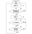
- FIG. 2 is a flowchart showing an outline of the flow of processing for ignoring detected coordinates in a specific range in the information processing apparatus 1 using the present technology.
- Step S1 When the information processing apparatus 1 is activated, the CPU 6 first sets the information processing apparatus 1 to the normal mode. (Step S1)
- the coordinate position is the software that requires the input regardless of where the touch position is in all the areas (first area) of the touch screen 2. Be notified. That is, no non-detection area (second area) is provided on the touch screen 2. In other words, the touch screen 2 is active on the entire surface, and input can be made in the entire area of the display panel 4 (touch detection is possible).
- examples that require touch input reception in the normal mode include a swipe from the outer periphery of the display unit 30 and a full screen display state of an image.
- Step S2 the CPU 6 determines whether or not a GUI that requires a touch operation in all areas of the touch screen 2 is displayed.
- step S2 If the GUI requires a touch operation in the entire area (YES in step S2), the CPU 6 returns to step S1 and continues the process in the normal mode.
- Step S3 If the GUI does not require a touch operation in the entire area (NO in step S2), the CPU 6 sets the information processing apparatus 1 to the restriction mode. (Step S3)
- the CPU 6 detects the situation of the information processing apparatus 1 described above, and based on the situation, the CPU 6 sets a specific range (second area) in which the detected coordinates are ignored. That is, in the restriction mode, the intermediate layer analyzes the range in which the upper layer requires coordinates by touch input as described above. Then, only when coordinates included in a range (third region) requiring coordinates by touch input are input, the coordinates are transmitted to the upper layer. When coordinates that are not included in the range that requires coordinates by touch input are input, the input is ignored (invalidated) and is not transmitted to the upper layer. In addition, what kind of specific range is set in the situation of the information processing apparatus 1 will be described later.
- Step S4 the CPU 6 determines whether or not the user has performed a touch operation in a range where the upper layer requires coordinates by touch input.
- step S4 the CPU 6 continues the process of step S4 (waits for touch input).
- Step S5 the CPU 6 next determines whether or not a change has occurred in the screen display of the display unit 30.
- step S5 If there is no change in the screen display (NO in step S5), the CPU 6 returns the process to step S4.
- step S5 If there is a change in the screen display (YES in step S5), the CPU 6 returns to step S1 and continues the process.
- the reason why the process is returned to step S1 is that the screen displayed next due to the change in the screen display may be a screen that needs to accept any coordinate of the entire screen as an input.
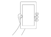
- FIG. 3 is an example in which a smartphone is used as the information processing apparatus 99, and is a diagram illustrating a state in which the user is holding with the right hand.
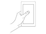
- FIG. 4 is a diagram illustrating a state in which the user performs touch input with respect to the information processing apparatus 99 using the thumb of the right hand.
- FIG. 5 shows that false detection occurs when the fingertip of the index finger, middle finger, ring finger, and little finger used to hold the information processing apparatus 99 or the base of the thumb performing touch input touches the touch screen. It is a figure which shows the area
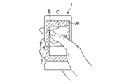
- FIG. 6 is a diagram illustrating one specific example in which a specific range in which the detected coordinates are ignored is set in the information processing apparatus 1 using the present technology.
- a smartphone is used as an example of the information processing apparatus 1, and it is assumed that the user holds the start phone with the right hand and operates with the thumb of the right hand.
- the outer peripheral portion of the screen of the display unit 30 including the region A in which erroneous detection may occur is set as the input ignoring region B (second region).
- an area inside the input ignoring area B set on the screen of the display unit 30 is set as the input possible area C.
- the width of the input ignoring area B may be a default value, may be set by the user, or may be changed depending on the size of the information processing apparatus 1 to which the present technology is applied. For example, when a smartphone of a size that can be grasped with one hand is used as the information processing apparatus 1, the user's hand is relatively large and the number of places touching the touch screen 2 increases. It can be considered large.
- a first restriction mode the type of restriction mode in which the input ignoring region B is provided on the outer periphery of the screen of the display unit 30 described here is referred to as a first restriction mode.
- Modification 1 a modification of the specific example in the first restriction mode will be described.
- the area on the screen is divided into area B and area C, but the size of the image displayed on the screen of the display unit 30 is not changed. For this reason, for example, when a GUI button displayed on the screen enters the input ignoring region B, a touch operation cannot be performed on the button.
- FIG. 7 is a diagram illustrating a state in which an image displayed on the screen of the display unit 30 is reduced to fit in the input-capable region C when the region on the screen is divided into the region B and the region C.
- FIG. 8 is a diagram illustrating another specific example of setting a specific range in which detected coordinates are ignored.
- three selection targets D specifically, three buttons (input unit) using icons and GUI are shown on the screen of the display unit 30.
- an input possible area E (third area) is provided around the selection target D and its surroundings, and among the areas where touch detection by the touch screen 2 is possible, the area excluding the input possible area E is ignored.
- area F (second area).
- the coordinate position of the selection target D must be recognized appropriately, but a generally used method may be applied as the recognition method.
- the source code of the software that displays the selection target D on the screen may be analyzed in advance, the binary code that is an execution file of the software may be analyzed in real time, or the selection target may be selected as a part of the GUI.
- the recognition may be performed at the timing when the GUI API for displaying D is called.
- the selection target D for example, there is a method of investigating a range in which the selection target D may be displayed when executing the software for each application software. For example, in the application software of the calculator, there is no change in the position where the selection target D is displayed from when the software starts up to when it ends. Therefore, the position of each button of the calculator that is the selection target D is checked, and when the calculator application is executed, an area including these buttons can be set as an inputable area.
- FIG. 9 is a diagram illustrating an example in which an input enabled area E and an input ignoring area F are provided on the screen of the display unit 30 of the information processing apparatus 1.
- restriction mode of the type in which only the selection target D and its surroundings are inputable area E described here will be referred to as a second restriction mode.
- the screen of the display unit 30 of the information processing apparatus 1 is expanded to the margin of the outer frame of the information processing apparatus 1, that is, the frame of the information processing apparatus The portion can be narrowed.
- the malfunction of the information processing apparatus 1 due to erroneous detection is reduced, it is possible to reduce the necessity for the user to perform a recovery process that had to be performed in order to recover the malfunction result when the malfunction occurred. Therefore, the time required for the recovery process can be saved, and the power required for the recovery process can be reduced to save power.
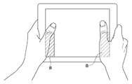
- FIG. 10 is a diagram illustrating a state in which the large tablet PC is held with both hands.
- the status of the information processing apparatus 99 is a situation where the user holds the information processing apparatus 99 or performs a screen operation.
- the touch operation to be detected in this situation is selection of the selection target D by the fingertip of the thumb or scrolling of the screen.
- the false detection occurs when the base of the thumb touches the touch screen.
- the information processing apparatus 1 can reduce false detection by adopting the first restriction mode and the second restriction mode.
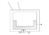
- the CPU 6 considers the signal from the attitude sensor 10 (detects that the information processing apparatus is held horizontally) and sets the input ignoring region B when the first restriction mode is adopted. This is an example in which only the lower half of the outer peripheral portion is provided, not the entire outer peripheral portion of the touch screen 2.
- FIG. 12 is a diagram illustrating a state in which the large tablet PC is held with one hand.
- the status of the information processing apparatus 99 is a situation where the user holds the information processing apparatus 99 or performs a screen operation.
- the touch operation to be detected in this situation is selection of the selection target D by the fingertip of the thumb or scrolling of the screen.
- the false detection occurs when the base of the thumb touches the touch screen.
- FIG. 13 shows the input ignoring region B when the CPU 6 takes the first restriction mode in consideration of the signal from the attitude sensor 10 (detects that the information processing apparatus is held horizontally). This is an example in which only the lower half of the outer peripheral portion is provided, not the entire outer peripheral portion of the touch screen 2.
- FIG. 14 is a diagram illustrating a state in which a large tablet PC is carried.
- the situation of the information processing apparatus 99 is a situation in which the user holds the information processing apparatus 99 with one hand from below. There is no touch operation to be detected in this situation.
- the erroneous detection occurs when the fingertip holding the information processing apparatus 99 touches the touch screen.
- FIG. 15 shows that the input ignoring area B is set when the CPU 6 takes the first restriction mode in consideration of the signal from the attitude sensor 10 (detects that the information processing apparatus is held horizontally). This is an example in which only the lower half of the outer peripheral portion is provided, not the entire outer peripheral portion of the touch screen 2.
- the range in which the input ignoring area B is provided is defined as the touch screen 2. That is, it can be limited to only the lower half of the outer peripheral portion, not the entire outer peripheral portion.
- FIG. 16 is a diagram illustrating a state in which the small tablet PC is held with both hands.
- the status of the information processing apparatus 99 is a situation where the user holds the information processing apparatus 99 or performs a screen operation.
- the touch operation to be detected in this situation is selection of the selection target D by the fingertip of the thumb or scrolling of the screen.
- the false detection occurs when the base of the thumb touches the touch screen.
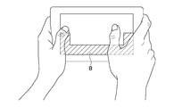
- FIG. 17 shows the input ignoring area B when the CPU 6 takes the first restriction mode in consideration of the signal from the attitude sensor 10 (detects that the information processing apparatus is held horizontally). This is an example in which only the lower half of the outer peripheral portion is provided, not the entire outer peripheral portion of the touch screen 2.
- FIG. 18 is a diagram illustrating a state in which the small tablet PC is held with one hand. In this case, the user holds the small tablet PC from the back side.
- the status of the information processing device 99 is a status in which the user holds the information processing device 99, performs a screen operation, or is carrying it.
- the touch operation to be detected in this situation is selection of the selection target D by the fingertip of the thumb or scrolling of the screen in the case of screen operation or scrolling, and is not particularly in the case of carrying.
- the erroneous detection occurs when the fingertip of the finger holding the information processing apparatus 99 touches the touch screen.
- the information processing apparatus 1 can reduce false detection by adopting the first restriction mode and the second restriction mode.
- the CPU 6 considers the signal from the attitude sensor 10 (detects that the information processing apparatus is held vertically) and sets the input ignoring region B when the first restriction mode is adopted.
- the touch screen 2 is provided only on the left and right sides of the outer peripheral portion, not the entire outer peripheral portion.
- FIG. 20 is a diagram illustrating a state in which the small tablet PC is held with one hand. In this case, the user holds the left side of the small tablet PC.
- the status of the information processing device 99 is a status in which the user holds the information processing device 99, performs a screen operation, or is carrying it.
- the touch operation desired to be detected in this situation is selection of the selection target D by the fingertip of the thumb in the case of screen operation or scrolling, and there is no particular case in the case of carrying.
- the erroneous detection occurs when the base of the thumb holding the information processing apparatus 99 touches the touch screen.
- the information processing apparatus 1 can reduce false detection by adopting the first restriction mode.
- the CPU 6 considers the signal from the attitude sensor 10 (detects that the information processing apparatus is held vertically) and sets the input ignoring region B when the first restriction mode is adopted.
- the touch screen 2 is provided only on the left and right sides of the outer peripheral portion, not the entire outer peripheral portion.
- the countermeasure patterns for various false detections when a user holds a small tablet we summarized the countermeasure patterns for various false detections when a user holds a small tablet. What can be said from these is that when it is found that the tablet is held horizontally by using the signal from the posture sensor 10, when the first restriction mode is adopted, the range in which the input ignoring area B is provided is defined as a touch screen. It can be limited to only the lower half of the outer peripheral portion, not the entire outer peripheral portion. Further, when the tablet is held vertically, the range in which the input ignoring area B is provided can be limited to only the left and right sides of the outer peripheral portion of the touch screen 2 when the first restriction mode is adopted.
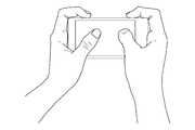
- FIG. 22 is a diagram illustrating a state in which the smartphone is held with both hands.
- the status of the information processing apparatus 99 is a situation where the user holds the information processing apparatus 99 or performs a screen operation.
- the touch operation to be detected in this situation is selection of the selection target D by the fingertip of the thumb.
- the false detection occurs when the base of the thumb touches the touch screen.
- FIG. 23 shows an example in which the input ignoring region B is provided on the entire outer periphery of the touch screen 2 when the CPU 6 adopts the first restriction mode.
- the input ignoring region B is provided on the entire outer peripheral portion of the touch screen 2. Is preferred.
- FIG. 24 is a diagram illustrating a state in which the smartphone is held with one hand.
- the status of the information processing device 99 is a status in which the user holds the information processing device 99, performs a screen operation, or is carrying it.
- the touch operation to be detected in this situation is the selection of the selection target D by the fingertip of the thumb in the case of the screen operation, and is not particularly in the case of holding or carrying.
- the erroneous detection occurs when the base of the thumb or the fingertip from the index finger to the little finger touches the touch screen.
- FIG. 25 is an example in which the input ignoring region B is provided on the entire outer peripheral portion of the touch screen 2 when the CPU 6 adopts the first restriction mode.
- FIG. 26 is a diagram illustrating a state in which the smartphone is held with one hand.
- the holding method shown in this figure is different from the holding method shown in the previous figure in that the degree of freedom of the thumb used for screen operation is increased, and in this state, the fingertip from the index finger to the little finger is used. Is not in a position to touch the touch screen.
- the situation of the information processing apparatus 99 is a situation where the user holds the information processing apparatus 99 or performs a screen operation.
- the touch operation to be detected in this situation is the selection of the selection target D by the fingertip of the thumb in the case of a screen operation, and is not particularly in the case of holding.
- the false detection occurs when the base of the thumb touches the touch screen.
- FIG. 27 shows an example in which the input ignoring region B is provided on the entire outer peripheral portion of the touch screen 2 when the CPU 6 adopts the first restriction mode.
- FIG. 28 is a diagram illustrating a state in which the smartphone is held with one hand.
- the holding method shown in this figure is different from the holding method shown in the previous figure in that an index finger is used in addition to the thumb as a finger used for screen operation.
- the situation of the information processing apparatus 99 is a situation where the user holds the information processing apparatus 99 or performs a screen operation.
- the touch operation to be detected in this situation is a pinch-in or pinch-out by the fingertip of the thumb and forefinger in the case of a screen operation, and is not particularly in the case of holding.
- the false detection occurs when the base of the thumb or index finger touches the touch screen.
- the information processing apparatus 1 can reduce false detection by adopting the first restriction mode or the second restriction mode.
- FIG. 29 shows an example in which the input ignoring region B is provided on the entire outer periphery of the touch screen 2 when the CPU 6 adopts the first restriction mode.
- FIG. 30 is a diagram illustrating a state in which the smartphone is held with one hand.
- the way of holding shown in this figure is different from the way of holding shown in the previous figure in that all the fingers are entangled and held on the smartphone in order to hold the smartphone firmly so as not to fall.
- the situation of the information processing apparatus 99 is a situation where the user carries the information processing apparatus 99. There is no touch operation to be detected in this situation. And false detection occurs when the fingertips of all fingers touch the touch screen.
- FIG. 31 shows an example in which the input ignoring region B is provided on the entire outer peripheral portion of the touch screen 2 when the CPU 6 adopts the first restriction mode.
- the pattern of countermeasures for various false detections when a user holds a smartphone is summarized. What can be said from these is that since smartphones are small, they are held by users in various ways. Therefore, it is difficult to further narrow the range of the input ignoring region B from the outer peripheral portion of the touch screen 2 depending on the posture in which the smartphone is held. Therefore, in the above example, when the smartphone is held, the input ignoring region B is provided on the outer peripheral portion of the touch screen 2 regardless of the holding state.
- the first restriction mode is effective in any situation in which the information processing apparatus 1 is used, and in some cases, the second restriction mode is also effective. I understand that.
- the CPU 6 detects that the information processing apparatus 1 is in an appropriate state to apply the second restriction mode using the attitude sensor 10, and the second restriction mode is added to the first restriction mode. By applying, false detection can be further reduced.
- the screen mode is changed to the restriction mode from the normal mode.
- the present invention is not limited to this, and it is appropriate that the CPU 6 sets the information processing apparatus 1 to the restriction mode from the output of the attitude sensor 10. It may be configured to detect that the current state is present and to transition from the normal mode to the restricted mode.
- the touch screen 2 covers the outer periphery of the housing of the information processing apparatus 1 . That is, the touch screen 2 includes a region corresponding to the display panel 4 for detecting coordinates designated by the user and an extended region for detecting a position where the user holds the information processing apparatus 1. The detection area of the touch screen 2 is extended beyond the range of the display panel 4 to the outer periphery of the information processing apparatus 1, thereby detecting the position of the user's finger holding the information processing apparatus 1 using the touch screen 2. I can do it.
- the input ignoring area B can be set to a more limited range by determining in detail the position of the finger holding the information processing apparatus 1. More restricting the input ignoring area B means that the range that the user can use for the input operation is increased, and that the user can perform the input operation more smoothly and without a sense of incongruity.
- a configuration using the output of the posture sensor 10 may also be used.
- the holding state of the information processing apparatus 1 can be determined more accurately.
- the configuration in which the touch screen 2 is extended to the outer peripheral portion of the information processing device 1 has been described.
- a configuration in which a sensor (second sensor, such as a pressure sensor or a thermal sensor) for detection is separately provided may be used.
- FIG. 32 is a diagram illustrating a setting example of the input ignoring region B when the large tablet is held with both hands using the configuration of the modified example. Compared to the case where only the output of the attitude sensor 10 is used, the input neglect area B in the lower center is eliminated.
- FIG. 33 is a diagram illustrating a setting example of the input ignoring region B when the large tablet is held with the right hand using the configuration of the modified example. Compared with the case of holding with both hands, the left input neglect area B is eliminated.
- FIG. 34 is a diagram illustrating a setting example of the input ignoring region B when the large tablet is carried with the left hand using the configuration of the modified example. Compared to the case where only the output of the attitude sensor 10 is used, the input ignoring region B is limited to the lower central portion.
- FIG. 35 is a diagram illustrating a setting example of the input ignoring region B when the small tablet is held with both hands using the configuration of the modified example. Compared to the case where only the output of the attitude sensor 10 is used, the input neglect area B in the lower center is eliminated.
- FIG. 36 is a diagram illustrating a setting example of the input ignoring region B when the small tablet is held from behind with the left hand using the configuration of the modified example. Compared with the case where only the output of the attitude sensor 10 is used, the left and right input ignoring regions B are further limited.
- FIG. 37 is a diagram illustrating a setting example of the input ignoring region B when the small tablet is held from the left side with the left hand using the configuration of the modified example. Compared to the case of holding from behind with the left hand, the input neglect area B on the right side is eliminated.
- FIG. 38 is a diagram illustrating a setting example of the input ignoring region B when the smartphone is held with both hands using the configuration of the modified example. Compared to the case where only the output of the attitude sensor 10 is used, the input ignoring region B at the center of both the upper and lower sides is eliminated.
- FIG. 39 is a diagram illustrating a setting example of the input ignoring region B when the smartphone is held with the left hand using the configuration of the modified example. Compared to the case where only the output of the attitude sensor 10 is used, the input ignoring area B at the center on both the upper and lower sides is eliminated, and the input ignoring area B on both the left and right sides is also limited.
- FIG. 40 is a diagram illustrating a setting example of the input ignoring region B when the smartphone is pinched with the left hand using the configuration of the modified example. Compared to the case where only the output of the attitude sensor 10 is used, the input ignoring region B is limited to a very small range.
- FIG. 41 is a diagram illustrating a setting example of the input ignoring region B when the smartphone is carried with the left hand using the configuration of the modified example. Compared to the case where only the output of the attitude sensor 10 is used, the input ignoring region B is limited.
- this technique can also take the following structures.
- a display panel A sensor panel that is arranged over the display panel and detects coordinates instructed by a user; The area that can be detected by the sensor panel as the first area, Setting a second region in at least a portion of the first region; A control unit that invalidates the coordinates detected in the second region.
- the controller is Analyzing the screen information displayed on the display panel, The information processing apparatus sets the second region when the analysis result satisfies a predetermined condition.
- the information processing apparatus according to (1) or (2), The controller is The information processing apparatus, wherein the second area is provided on an outer peripheral portion of the first area.
- the information processing apparatus according to any one of (1) to (3), A first sensor that detects a posture in which the information processing apparatus is held; The control unit sets the second region based on the detected posture. Information processing apparatus.
- the display panel has different vertical and horizontal lengths, The controller is When the display panel is held in a vertically long posture, the second area is set on both sides in a direction orthogonal to the longitudinal direction of the first area, When the display panel is held in a horizontally long posture, the second area is set on both sides in the longitudinal direction of the first area and on the lower side of the first area in this posture.
- the information processing apparatus is When the second area is set, the information on the screen is displayed in an area inside the second area.
- the information processing apparatus includes an area corresponding to the display panel that detects coordinates instructed by a user, and an area that functions as a second sensor that detects a finger position of the user holding the information processing apparatus. Information processing device.
- the information processing apparatus is A third region that is displayed in at least a portion of the first region, is assigned a predetermined process, and is selectable by the user; An information processing apparatus that sets an area other than the third area in the first area as the second area.
- the information processing apparatus according to (9), The third area is an icon.
- the information processing apparatus according to (9), The third area is an input unit of a graphical user interface.
- An area that is arranged on the display panel and that can be detected by a sensor panel that detects coordinates instructed by the user is defined as a first area.
- the control unit Setting a second region in at least a portion of the first region; An information processing method for invalidating the coordinates detected in the second region.
Landscapes
- Engineering & Computer Science (AREA)
- General Engineering & Computer Science (AREA)
- Theoretical Computer Science (AREA)
- Human Computer Interaction (AREA)
- Physics & Mathematics (AREA)
- General Physics & Mathematics (AREA)
- User Interface Of Digital Computer (AREA)
- Position Input By Displaying (AREA)
Abstract
この情報処理装置は、表示パネルと、前記表示パネル上に重ねて配置され、ユーザにより指示された座標を検出するセンサパネルと、前記センサパネルにより検出可能な領域を第1の領域として、前記第1の領域の少なくとも一部に第2の領域を設定し、前記第2の領域において検出された前記座標を無効とする制御部とを具備する。
Description
本技術は、操作入力に用いるタッチパネルを備えた情報処理装置および情報処理方法に関する。
最近、スレート型パーソナルコンピュータ(PC)であるタブレットPCやスマートフォンなど、ハンドヘルド型の情報処理装置が普及してきた。これらの機器は、通常、PCのようにマウスやキーボードを備えておらず、表示画面上に設けられたタッチスクリーンを用いてユーザからの操作入力を受け付ける。
タッチスクリーンを用いて柔軟な入力操作を行うために、ユーザがタッチスクリーン上で複数箇所同時にタッチした場合でも、各タッチ位置を検出可能なタッチパネルが開発されている(例えば、特許文献1参照)。
このようなタッチパネルを用いた入力系では、表示画面上の操作説明に入力動作が対応するため、ユーザはどのような操作をすべきか直感的に分かりやすくなり、操作が簡単になるという長所がある。
上述したように、入力操作を直感的に分かりやすく行えるタッチパネルを備えたハンドヘルド型の情報処理装置の普及が進んでいる。しかし、ユーザが意図せずタッチパネルに触れた場合に誤検出が生じるなど、タッチパネルを備えた情報処理装置のユーザインタフェースには、改善すべき点があった。
以上のような事情に鑑み、本技術の目的は、タッチパネルを備えた情報処理装置において、ユーザインタフェースの操作性を向上させた情報処理装置および情報処理方法を提供することにある。
上記目的を達成するため、本技術の一形態に係る情報処理装置は、表示パネルと、前記表示パネル上に重ねて配置され、ユーザにより指示された座標を検出するセンサパネルと、前記センサパネルにより検出可能な領域を第1の領域として、前記第1の領域の少なくとも一部に第2の領域を設定し、前記第2の領域において検出された前記座標を無効とする制御部とを具備する。
上記目的を達成するため、本技術の一形態に係る情報処理装置では、前記制御部は、前記表示パネルに表示される画面の情報を解析し、前記解析結果が所定の条件を満たすとき、前記第2の領域を設定してもよい。
上記目的を達成するため、本技術の一形態に係る情報処理装置では、前記制御部は、前記第2の領域を、前記第1の領域の外周部に設けてもよい。
上記目的を達成するため、本技術の一形態に係る情報処理装置では、当該情報処理装置が保持される姿勢を検出する第1のセンサをさらに具備し、前記制御部は、検出された前記姿勢に基づいて、前記第2の領域を設定してもよい。
上記目的を達成するため、本技術の一形態に係る情報処理装置では、前記表示パネルは、縦横の長さが異なり、前記制御部は、前記表示パネルが縦長の姿勢で保持されるとき、前記第2の領域を前記第1の領域の長手方向に直交する方向の両側に設定し、前記表示パネルが横長の姿勢で保持されるとき、前記第2の領域を前記第1の領域の長手方向の両側と前記第1の領域のこの姿勢における下側に設定してもよい。
上記目的を達成するため、本技術の一形態に係る情報処理装置では、前記制御部は、前記第2の領域が設定されている時、前記画面の情報を、前記第2の領域より内側の領域に表示してもよい。
上記目的を達成するため、本技術の一形態に係る情報処理装置では、当該情報処理装置を保持するユーザの指位置を検出する第2のセンサをさらに備え、前記制御部は、検出された前記指位置に基づいて、前記第2の領域を設定してもよい。
上記目的を達成するため、本技術の一形態に係る情報処理装置では、前記センサパネルは、ユーザにより指示された座標を検出する、前記表示パネルに対応した領域と、当該情報処理装置を保持するユーザの指位置を検出する第2のセンサとして機能する領域とから構成されてもよい。
上記目的を達成するため、本技術の一形態に係る情報処理装置では、前記制御部は、前記第1の領域の少なくとも一部に表示され、所定の処理が割り当てられ、ユーザにより選択可能な第3の領域を判別し、前記第1の領域のうち、前記第3の領域以外の領域を、前記第2の領域として設定してもよい。
上記目的を達成するため、本技術の一形態に係る情報処理装置では、前記第3の領域は、アイコンであってもよい。
上記目的を達成するため、本技術の一形態に係る情報処理装置では、前記第3の領域は、グラフィカル・ユーザ・インタフェースの入力部であってもよい。
上記目的を達成するため、本技術の一形態に係る情報処理方法では、表示パネル上に重ねて配置され、ユーザにより指示された座標を検出するセンサパネルにより検出可能な領域を第1の領域として、制御部が、前記第1の領域の少なくとも一部に第2の領域を設定し、前記第2の領域において検出された前記座標を無効とする。
以上のように、本技術によれば、タッチパネルを備えた情報処理装置において、ユーザインタフェースの操作性を向上させることが出来る。なお、ここに記載された効果は必ずしも限定されるものではなく、本開示中に記載されたいずれかの効果であってもよい。
以下、本技術に係る実施形態を、図面を参照しながら説明する。なお、以下では、タッチスクリーンに指でタッチした場合を想定して説明を行う。手袋をした指を用いる場合やスタイラスペンを用いる場合も、タッチスクリーンでの検出感度が多少異なるだけであるので、基本的には同じように扱うことが出来る。
[情報処理装置の構成]
最初に、本技術に係る、タッチパネルを備えた情報処理装置の構成の例について説明する。図1は、本技術に係る、タッチパネルを備えた情報処理装置の構成図である。
最初に、本技術に係る、タッチパネルを備えた情報処理装置の構成の例について説明する。図1は、本技術に係る、タッチパネルを備えた情報処理装置の構成図である。
情報処理装置1は、タッチスクリーン(センサパネル)2、プロセッサ3、表示パネル4、駆動ドライバ5、演算制御を行うCPU(Central Processing Unit)(制御部)6、ROM(Read Only Memory)7、CPU6のワークメモリ(作業領域)となるRAM(Random Access Memory)8、バックアップメモリ9、姿勢センサ10(第1のセンサ)、およびこれらを互いに接続するバス11を備えている。
タッチスクリーン2およびプロセッサ3により入力部20が構成され、表示パネル4および駆動ドライバ5により表示部30が構成され、CPU6、ROM7、およびRAM8によりマイクロコンピュータが構成される。
タッチスクリーン(センサパネル)2は、ユーザによるタッチ入力を座標として検出する。検出方法には、静電容量式、感圧式、光学式などがある。本技術では、どの方式のタッチスクリーンを用いてもよい。タッチスクリーン2の、ユーザの入力を検知出来る領域(第1の領域)は、通常、表示パネル4の画面の大きさに基づいて設定される。
表示パネル4は、駆動ドライバ5により駆動・制御され、表示画面上に図形や文字を表示する。表示パネルには、液晶パネル、有機EL(Electro Luminescence)パネル、電子ペーパーなど、タッチスクリーン2と重ねて用いることが可能なものであれば、どのような表示パネルを用いてもよい。駆動ドライバ5は、ユーザがタッチスクリーン2を介して指示した入力操作等に基づいてCPU6が生成した文字や図形、画像などを処理して表示パネル4の表示画面上に表示する。
ROM7には、各種の処理を実行するためのプログラムが格納される。姿勢センサ10は、加速度センサや傾きセンサ、ジャイロセンサなどであり、ユーザが情報処理装置1を保持する際の情報処理装置1の姿勢を検出したり、情報処理装置1の持ち運びが行われている事を検出したりする。バックアップメモリ9には、ユーザデータやプログラムデータを長期保存するために、HDD(Hard Disk Drive)などの磁気ディスク、フラッシュメモリなどの半導体メモリ等が適用される。
CPU6は、ROM7およびバックアップメモリ9等に格納される複数のプログラムのうち、タッチスクリーン2から与えられる命令等に対応するプログラムをRAM7に展開し、該展開したプログラムにしたがって、駆動ドライバ5を適宜制御する。
本技術は、タッチスクリーン2によりユーザがタッチした位置として検出した座標のうち、特定の範囲の座標を無視する(不検知とする)ものであり、どの範囲の座標を無視するかは、特定のプログラムをCPU6が実行することにより判断される。この特定のプログラムは、情報処理装置1のファームウェアとして実現されてもよいし、OS(Operating System)の一部として実現されてもよいし、OSと各アプリケーションソフトウェアの中間に位置するミドルウェアとして実現されてもよいし、特定のアプリケーションソフトウェアとして実現されてもよいし、これらの組み合わせにより実現されてもよい。
なお、以下の説明では、便宜上、この特定のプログラムを実行するCPU6が、特定の範囲の検知座標を無視するものとして説明を行う。なお、ここでいう特定の範囲の検知座標の無視とは、より具体的には、OSやアプリケーションソフトウェアにより表示部30に表示されるGUI(Graphical User Interface)のうち、入力に用いる入力可能領域(第3の領域)をCPU6が判別し、この入力可能領域以外の領域(第2の領域)においてタッチスクリーン2で検知された座標を、CPU6がタッチ位置検知アルゴリズムから排除するということである。
別の言い方をするならば、本技術の情報処理装置1は、表示パネル4と、表示パネル4上に重ねて配置され、ユーザにより指示された座標を検出するタッチスクリーン2と、タッチスクリーン2により検出可能な領域を第1の領域として、第1の領域の少なくとも一部に第2の領域を設定し、第2の領域において検出された前記座標を無効とするCPU6とを具備している。
さらに別の言い方をするならば、本技術に係る情報処理装置1は、大きく分けて、3つのレイヤ、下位レイヤ、中間レイヤ、上位レイヤから構成されていると考えられる。下位レイヤは、タッチスクリーン2およびプロセッサ3などから構成されるハードウェアレイヤである。上位レイヤは、ユーザによりタッチ入力された座標を用いて特定の処理を行うソフトウェアレイヤである。中間レイヤは、下位レイヤから伝達された、ユーザによりタッチ入力された座標を、情報処理装置1の状況に応じて、上位レイヤに伝達したり、伝達しなかったりするソフトウェアレイヤである。なお、中間レイヤおよび上位レイヤがハードウェアにより構成されていても構わない。
なお、ここでいう情報処理装置1の状況とは、例えば、情報処理装置1上で起動されているソフトウェアの種類や、それらソフトウェアにより表示部30に表示されているGUIの状態(どの領域にタッチ可能なボタン等が描画されているか等)、ユーザによる情報処理装置1の保持状態(両手で保持、片手で保持、持ち運び中など)である。
以上、本技術に係る、タッチパネルを備えた情報処理装置の構成の例について説明した。
[本技術における処理の流れ(概要)]
次に、本技術を用いた情報処理装置1において、特定範囲の検知座標を無視する処理の流れの概要について説明する。図2は、本技術を用いた情報処理装置1において、特定範囲の検知座標を無視する処理の流れの概要を表すフローチャートである。
次に、本技術を用いた情報処理装置1において、特定範囲の検知座標を無視する処理の流れの概要について説明する。図2は、本技術を用いた情報処理装置1において、特定範囲の検知座標を無視する処理の流れの概要を表すフローチャートである。
情報処理装置1が起動されると、CPU6は、まず、情報処理装置1を通常モードに設定する。(ステップS1)
通常モードでは、ユーザのタッチ入力があった際に、そのタッチ位置がタッチスクリーン2の全ての領域(第1の領域)のどこであっても、その座標位置が、その入力を必要とするソフトウェアに通知される。すなわち、タッチスクリーン2上には、不検知領域(第2の領域)は設けられない。別の言い方をするならば、タッチスクリーン2が全面アクティブであり、表示パネル4の全領域において入力が可能(タッチ検出可能)ということである。
なお、通常モードでのタッチ入力受け付けが必要な例として、表示部30の外周部からのスワイプや画像の全画面表示状態などがある。
次に、CPU6は、タッチスクリーン2の全ての領域におけるタッチ操作が必要なGUIが表示されているか否かを判断する。(ステップS2)
全領域でのタッチ操作が必要なGUIである場合(ステップS2のYES)、CPU6は、ステップS1に戻って通常モードでの処理を継続する。
全領域でのタッチ操作が必要なGUIではない場合(ステップS2のNO)、CPU6は、情報処理装置1を制限モードに設定する。(ステップS3)
制限モードでは、上述した情報処理装置1の状況をCPU6が検知して、その状況に基づいてCPU6が検知座標を無視する特定の範囲(第2の領域)を設定する。すなわち、制限モードでは、中間レイヤは、上述したとおり、タッチ入力による座標を上位レイヤが必要とする範囲を解析する。そして、タッチ入力による座標を必要とする範囲(第3の領域)に含まれる座標が入力された場合に限り、その座標を上位レイヤに伝達する。タッチ入力による座標を必要とする範囲に含まれない座標が入力された場合は、その入力を無視し(無効とし)、上位レイヤへの伝達は行われない。なお、どのような情報処理装置1の状況の場合に、どのような特定の範囲を設定するかは、後述する。
次に、CPU6は、上位レイヤがタッチ入力による座標を必要とする範囲において、ユーザによるタッチ操作が行われたか否かを判断する。(ステップS4)
タッチ操作が行われなかった場合(ステップS4のNO)、CPU6は、ステップS4の処理を継続する(タッチ入力を待機する)。
タッチ操作が行われた場合(ステップS4のYES)、CPU6は、次に、表示部30の画面表示に変化が起こったか否かを判断する。(ステップS5)
画面表示に変化が無かった場合(ステップS5のNO)、CPU6は、ステップS4に処理を戻す。
画面表示に変化が有った場合(ステップS5のYES)、CPU6は、ステップS1に戻り処理を継続する。ステップS1に処理を戻すのは、画面表示の変化により次に表示された画面が、全画面のいずれかの座標を入力として受け付ける必要がある画面である可能性があるからである。
以上、本技術を用いた情報処理装置1において、特定範囲の検知座標を無視する処理の流れの概要について説明した。
[検知座標を無視する特定範囲の設定例について]
次に、CPU6により設定される、検知座標を無視する特定範囲の設定例について説明する。
次に、CPU6により設定される、検知座標を無視する特定範囲の設定例について説明する。
(本技術を用いない例)
最初に、本技術を用いない情報処理装置99での誤検出の例を説明する。図3は、情報処理装置99としてスマートフォンを用いた例であり、ユーザが右手で保持している状態を示す図である。
最初に、本技術を用いない情報処理装置99での誤検出の例を説明する。図3は、情報処理装置99としてスマートフォンを用いた例であり、ユーザが右手で保持している状態を示す図である。
この図に示す状態から、ユーザは、例えば右手の親指を動かしてタッチ入力を行う。図4は、情報処理装置99に対してユーザが右手の親指を用いてタッチ入力を行っている様子を示す図である。
ユーザがこのようなタッチ入力を行う際、親指の指先以外、すなわち、情報処理装置99を保持するために用いている、人差し指、中指、薬指、および小指の指先や、タッチ入力を行っている親指の付け根がタッチスクリーンに触れることにより誤検出が発生する可能性がある。図5は、情報処理装置99を保持するために用いている、人差し指、中指、薬指、および小指の指先や、タッチ入力を行っている親指の付け根がタッチスクリーンに触れることにより誤検出が発生する可能性がある領域Aを示す図である。
以上、本技術を用いない情報処理装置99での誤検出の例について説明した。
(第1の制限モード)
次に、この誤検出を低減するために、本技術を用いた情報処理装置1において、検知座標を無視する特定範囲を設定した具体例の1つを説明する。図6は、本技術を用いた情報処理装置1において、検知座標を無視する特定範囲を設定した具体例の1つを示す図である。なお、この図でも情報処理装置1としてスマートフォンを例に挙げており、ユーザがスタートフォンを右手で保持し、右手の親指で操作する状態を想定している。
次に、この誤検出を低減するために、本技術を用いた情報処理装置1において、検知座標を無視する特定範囲を設定した具体例の1つを説明する。図6は、本技術を用いた情報処理装置1において、検知座標を無視する特定範囲を設定した具体例の1つを示す図である。なお、この図でも情報処理装置1としてスマートフォンを例に挙げており、ユーザがスタートフォンを右手で保持し、右手の親指で操作する状態を想定している。
本技術では、この図にあるように、誤検出が発生する可能性がある領域Aを含む表示部30の画面の外周部を、入力無視領域B(第2の領域)として設定する。同時に、表示部30の画面に設定する入力無視領域Bよりも内側の領域を、入力可能領域Cとして設定する。
入力無視領域Bの幅は、既定値を用いてもよいし、ユーザにより設定されてもよいし、本技術を適用する情報処理装置1の大きさにより変更してもよい。例えば、情報処理装置1として片手で握ることが出来るサイズのスマートフォンを用いる場合、ユーザの手は相対的に大きくなりタッチスクリーン2に触れる箇所が増えるので、入力無視領域Bを設ける外周部の幅を大きく取ることが考えられる。
逆に、例えば、情報処理装置1として画面サイズが10インチ程度の大型のタブレットPCを用いる場合、ユーザの手は相対的に小さくなりタッチスクリーン2に触れる箇所は減少するので、入力無視領域Bの幅を細くすることが考えられる。
入力無視領域Bを設定することにより、この領域Bにユーザが意図するタッチ入力に用いる指以外が触れても、その接触を誤検出する可能性を低減することが出来る。
なお、以下の説明では、ここで説明した、表示部30の画面の外周部に入力無視領域Bを設けるタイプの制限モードを第1の制限モードと呼ぶ。
以上、本技術を用いた情報処理装置1において、検知座標を無視する特定範囲を設定した具体例の1つを説明した。
(変形例1)
ここでは、第1の制限モードでの具体例の変形例を説明する。図6に示す具体例では、画面上の領域を領域Bと領域Cに分けたが、表示部30の画面に表示される画像のサイズに対しては変更を行わなかった。そのため、例えば、画面上に表示されるGUIのボタンが入力無視領域Bに入った場合、そのボタンに対するタッチ操作を行うことは出来なかった。
ここでは、第1の制限モードでの具体例の変形例を説明する。図6に示す具体例では、画面上の領域を領域Bと領域Cに分けたが、表示部30の画面に表示される画像のサイズに対しては変更を行わなかった。そのため、例えば、画面上に表示されるGUIのボタンが入力無視領域Bに入った場合、そのボタンに対するタッチ操作を行うことは出来なかった。
それに対し、この変形例では、画面上の領域を領域Bと領域Cに分ける際、表示部30の画面に表示される画像を、入力可能領域Cに収まるように縮小する。図7は、画面上の領域を領域Bと領域Cに分ける際、表示部30の画面に表示される画像を、入力可能領域Cに収まるように縮小した様子を示す図である。この構成とすることにより、例えば、画面上に表示されるGUIのボタンなどは、縮小される分小さくはなるものの、全て入力可能領域Cに含まれるので、タッチ操作が出来なくなることを防止することが出来る。
以上、第1の制限モードでの変形例について説明した。
(第2の制限モード)
次に、上述した例と同様に、検知座標を無視する特定範囲を設定する別の具体例を説明する。図8は、検知座標を無視する特定範囲を設定する別の具体例を示す図である。図にあるように、この例では、表示部30の画面上に、3つの選択対象D、具体的には、アイコンやGUIによる3つのボタン(入力部)が示されている。
次に、上述した例と同様に、検知座標を無視する特定範囲を設定する別の具体例を説明する。図8は、検知座標を無視する特定範囲を設定する別の具体例を示す図である。図にあるように、この例では、表示部30の画面上に、3つの選択対象D、具体的には、アイコンやGUIによる3つのボタン(入力部)が示されている。
本技術では、これら選択対象Dおよびその周囲に入力可能領域E(第3の領域)を設け、タッチスクリーン2によるタッチ検出が可能な領域のうち、入力可能領域Eを除いた領域を、入力無視領域F(第2の領域)として設定する。
入力可能領域Eを設けるためには、適切に選択対象Dの座標位置を認識しなければならないが、認識方法は一般的に用いられる方法を適用すればよい。
例えば、選択対象Dを画面上に表示するソフトウェアのソースコードを予め解析してもよいし、そのソフトウェアの実行ファイルであるバイナリコードをリアルタイムで解析してもよいし、GUIの一部として選択対象Dを表示するためのGUI用APIが呼び出されるタイミングで認識を行ってもよい。
選択対象Dを認識する別の方法としては、例えば、アプリケーションソフトウェアごとに、そのソフトウェア実行時に選択対象Dを表示する可能性がある範囲を調査しておくという方法がある。例えば、電卓のアプリケーションソフトウェアでは、ソフトウェアの起動時から終了時まで、選択対象Dが表示される位置に変化はない。そこで、選択対象Dである電卓の各ボタンの位置を調べておき、電卓アプリの実行時には、それらのボタンを含む領域を入力可能領域とすることも出来る。
図9は、情報処理装置1の表示部30の画面上に、入力可能領域Eおよび入力無視領域Fを設けた例を示す図である。
入力無視領域Fを設定することにより、この領域Fにユーザが意図するタッチ入力に用いる指以外が触れても、その接触を誤検出する可能性を低減することが出来る。
なお、以下の説明では、ここで説明した、選択対象Dおよびその周囲のみを入力可能領域Eとするタイプの制限モードを第2の制限モードと呼ぶ。
なお、上記では、第1の制限モードと第2の制限モードとを独立して説明したが、これらの制限モードは、同時に併用することも可能である。
以上、本技術を用いた情報処理装置1において、検知座標を無視する特定範囲を設定する別の具体例について説明した。
[その他の効果について]
本技術を用いることにより、上述した効果に加え、以下の様な効果を得ることも可能である。
本技術を用いることにより、上述した効果に加え、以下の様な効果を得ることも可能である。
例えば、情報処理装置1の表示部30の画面の周辺部における誤検出を低減出来ることから、表示部30の画面を情報処理装置1の外枠ぎりぎりの所まで広げる、すなわち、情報処理装置の額縁部分の狭小化を行うことが出来る。
また、誤検出が低減できるので、本来検出すべきタッチ入力の検出精度を向上させることが出来る。
また、誤検出による情報処理装置1の誤動作が減るので、誤動作が発生した場合に、ユーザが誤動作の結果をリカバリするために行わなければならなかったリカバリ処理を行う必要が削減出来る。そのため、リカバリ処理に要していた時間を節約したり、リカバリ処理に必要であった電力を削減し省電力化を図ったりすることが出来る。
以上、本技術を用いた場合の、その他の効果について説明した。
[情報処理装置1の状況ごとの特定範囲の設定例について]
次に、本技術を適用していない情報処理装置99において誤検出が発生する状況と、本技術を用いた情報処理装置1における、当該状況ごとの特定範囲の設定例について個別に説明する。なお、ここでは、情報処理装置1の例として、画面サイズが10インチ前後の大型タブレットPC、画面サイズが7インチ前後の小型タブレットPC、およびスマートフォンを用いる。また、これらの機器をユーザが両手で保持した場合と片手で保持した場合とに分けて説明する。
次に、本技術を適用していない情報処理装置99において誤検出が発生する状況と、本技術を用いた情報処理装置1における、当該状況ごとの特定範囲の設定例について個別に説明する。なお、ここでは、情報処理装置1の例として、画面サイズが10インチ前後の大型タブレットPC、画面サイズが7インチ前後の小型タブレットPC、およびスマートフォンを用いる。また、これらの機器をユーザが両手で保持した場合と片手で保持した場合とに分けて説明する。
(大型タブレットを両手で保持する場合)
まず、大型タブレットPCを両手で保持する場合に発生する状況がどのようなものであるかを考える。図10は、大型タブレットPCを両手で保持する様子を示す図である。
まず、大型タブレットPCを両手で保持する場合に発生する状況がどのようなものであるかを考える。図10は、大型タブレットPCを両手で保持する様子を示す図である。
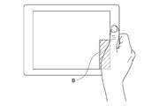
この図の場合、情報処理装置99の状況は、ユーザが情報処理装置99を保持しているか、または画面操作を行っている状況である。この状況で検出したいタッチ操作は、親指の指先による選択対象Dの選択、または画面のスクロールである。そして、誤検出は、親指の付け根がタッチスクリーンに触れることにより発生する。
このような場合、情報処理装置1では、第1の制限モードや第2の制限モードを採ることにより、誤検出を低減することが出来る。図11は、CPU6が、姿勢センサ10からの信号を考慮して(情報処理装置が横長に保持されていることを検知して)、第1の制限モードを採る際に、入力無視領域Bをタッチスクリーン2の外周部全体ではなく、外周部の下半分のみに設けた例である。
(大型タブレットを片手で保持する場合)
次に、大型タブレットPCを片手で保持する場合に発生する状況がどのようなものであるかを考える。図12は、大型タブレットPCを片手で保持する様子を示す図である。
次に、大型タブレットPCを片手で保持する場合に発生する状況がどのようなものであるかを考える。図12は、大型タブレットPCを片手で保持する様子を示す図である。
この図の場合、情報処理装置99の状況は、ユーザが情報処理装置99を保持しているか、または画面操作を行っている状況である。この状況で検出したいタッチ操作は、親指の指先による選択対象Dの選択、または画面のスクロールである。そして、誤検出は、親指の付け根がタッチスクリーンに触れることにより発生する。
このような場合、情報処理装置1では、第1の制限モードや第2の制限モードを採ることにより、誤検出を低減することが出来る。図13は、CPU6が、姿勢センサ10からの信号を考慮して(情報処理装置が横長に保持されていることを検知して)、第1の制限モードを採る際に、入力無視領域Bをタッチスクリーン2の外周部全体ではなく、外周部の下半分のみに設けた例である。
(大型タブレットを持ち運ぶ場合)
次に、大型タブレットPCを持ち運ぶ場合に発生する状況がどのようなものであるかを考える。図14は、大型タブレットPCを持ち運ぶ様子を示す図である。
次に、大型タブレットPCを持ち運ぶ場合に発生する状況がどのようなものであるかを考える。図14は、大型タブレットPCを持ち運ぶ様子を示す図である。
この図の場合、情報処理装置99の状況は、ユーザが情報処理装置99を下側から片手で保持している状況である。この状況で検出したいタッチ操作は、無い。そして、誤検出は、情報処理装置99を保持する指先がタッチスクリーンに触れることにより発生する。
このような場合、情報処理装置1では、第1の制限モードを採ることにより、誤検出を低減することが出来る。図15は、CPU6が、姿勢センサ10からの信号を考慮して(情報処理装置が横長に保持されていることを検知して)、第1の制限モードを採る際に、入力無視領域Bをタッチスクリーン2の外周部全体ではなく、外周部の下半分のみに設けた例である。
以上、大型タブレットをユーザが保持する際の様々な誤検出をその対策のパターンをまとめた。これらから言える事は、姿勢センサ10からの信号を用いることにより、タブレットが横長に保持されていることが分かるので、第1の制限モードを採る際、入力無視領域Bを設ける範囲をタッチスクリーン2の外周部全体ではなく、外周部の下半分のみに限定することが出来るという事である。
(小型タブレットを両手で保持する場合)
次に、小型タブレットPCを両手で保持する場合に発生する状況がどのようなものであるかを考える。図16は、小型タブレットPCを両手で保持する様子を示す図である。
次に、小型タブレットPCを両手で保持する場合に発生する状況がどのようなものであるかを考える。図16は、小型タブレットPCを両手で保持する様子を示す図である。
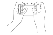
この図の場合、情報処理装置99の状況は、ユーザが情報処理装置99を保持しているか、または画面操作を行っている状況である。この状況で検出したいタッチ操作は、親指の指先による選択対象Dの選択、または画面のスクロールである。そして、誤検出は、親指の付け根がタッチスクリーンに触れることにより発生する。
このような場合、情報処理装置1では、第1の制限モードを採ることにより、誤検出を低減することが出来る。図17は、CPU6が、姿勢センサ10からの信号を考慮して(情報処理装置が横長に保持されていることを検知して)、第1の制限モードを採る際に、入力無視領域Bをタッチスクリーン2の外周部全体ではなく、外周部の下半分のみに設けた例である。
(小型タブレットを片手で保持する場合(その1))
次に、小型タブレットPCを片手で保持する場合(その1)に発生する状況がどのようなものであるかを考える。図18は、小型タブレットPCを片手で保持する様子を示す図である。なお、この場合、ユーザは小型タブレットPCをその後ろ側から保持する形となっている。
次に、小型タブレットPCを片手で保持する場合(その1)に発生する状況がどのようなものであるかを考える。図18は、小型タブレットPCを片手で保持する様子を示す図である。なお、この場合、ユーザは小型タブレットPCをその後ろ側から保持する形となっている。
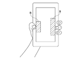
この図の場合、情報処理装置99の状況は、ユーザが情報処理装置99を保持しているか、画面操作を行っているか、または持ち運んでいる状況である。この状況で検出したいタッチ操作は、画面操作またはスクロールの場合は親指の指先による選択対象Dの選択、または画面のスクロールであり、持ち運びの場合は、特に無い。そして、誤検出は、情報処理装置99を保持している指の指先がタッチスクリーンに触れることにより発生する。
このような場合、情報処理装置1では、第1の制限モードや第2の制限モードを採ることにより、誤検出を低減することが出来る。図19は、CPU6が、姿勢センサ10からの信号を考慮して(情報処理装置が縦長に保持されていることを検知して)、第1の制限モードを採る際に、入力無視領域Bをタッチスクリーン2の外周部全体ではなく、外周部の左右のみに設けた例である。
(小型タブレットを片手で保持する場合(その2))
次に、小型タブレットPCを片手で保持する場合(その2)に発生する状況がどのようなものであるかを考える。図20は、小型タブレットPCを片手で保持する様子を示す図である。なお、この場合、ユーザは小型タブレットPCの、向かって左側を保持する形となっている。
次に、小型タブレットPCを片手で保持する場合(その2)に発生する状況がどのようなものであるかを考える。図20は、小型タブレットPCを片手で保持する様子を示す図である。なお、この場合、ユーザは小型タブレットPCの、向かって左側を保持する形となっている。
この図の場合、情報処理装置99の状況は、ユーザが情報処理装置99を保持しているか、画面操作を行っているか、または持ち運んでいる状況である。この状況で検出したいタッチ操作は、画面操作またはスクロールの場合は親指の指先による選択対象Dの選択であり、持ち運びの場合は、特に無い。そして、誤検出は、情報処理装置99を保持している親指の付け根がタッチスクリーンに触れることにより発生する。
このような場合、情報処理装置1では、第1の制限モードを採ることにより、誤検出を低減することが出来る。図21は、CPU6が、姿勢センサ10からの信号を考慮して(情報処理装置が縦長に保持されていることを検知して)、第1の制限モードを採る際に、入力無視領域Bをタッチスクリーン2の外周部全体ではなく、外周部の左右のみに設けた例である。
以上、小型タブレットをユーザが保持する際の様々な誤検出をその対策のパターンをまとめた。これらから言える事は、姿勢センサ10からの信号を用いることにより、タブレットが横長に保持されていることが分かった時、第1の制限モードを採る際、入力無視領域Bを設ける範囲をタッチスクリーン2の外周部全体ではなく、外周部の下半分のみに限定することが出来るという事である。また、タブレットが縦長に保持されている場合、第1の制限モードを採る際、入力無視領域Bを設ける範囲をタッチスクリーン2の外周部の左右のみに限定することが出来るという事である。
(スマートフォンを両手で保持する場合)
次に、スマートフォンを両手で保持する場合に発生する状況がどのようなものであるかを考える。図22は、スマートフォンを両手で保持する様子を示す図である。
次に、スマートフォンを両手で保持する場合に発生する状況がどのようなものであるかを考える。図22は、スマートフォンを両手で保持する様子を示す図である。
この図の場合、情報処理装置99の状況は、ユーザが情報処理装置99を保持しているか、または画面操作を行っている状況である。この状況で検出したいタッチ操作は、親指の指先による選択対象Dの選択である。そして、誤検出は、親指の付け根がタッチスクリーンに触れることにより発生する。
このような場合、情報処理装置1では、第1の制限モードを採ることにより、誤検出を低減することが出来る。図23は、CPU6が、第1の制限モードを採る際に、入力無視領域Bをタッチスクリーン2の外周部全体に設けた例である。なお、スマートフォンをユーザが保持する場合、保持が両手で行われるか片手で行われるかに関わらず、またスマートフォンの保持姿勢に関わらず、入力無視領域Bはタッチスクリーン2の外周部全体に設けることが好ましい。
(スマートフォンを片手で保持する場合(その1))
次に、スマートフォンを片手で保持する場合(その1)に発生する状況がどのようなものであるかを考える。図24は、スマートフォンを片手で保持する様子を示す図である。
次に、スマートフォンを片手で保持する場合(その1)に発生する状況がどのようなものであるかを考える。図24は、スマートフォンを片手で保持する様子を示す図である。
この図の場合、情報処理装置99の状況は、ユーザが情報処理装置99を保持しているか、画面操作を行っているか、または持ち運んでいる状況である。この状況で検出したいタッチ操作は、画面操作の場合は親指の指先による選択対象Dの選択であり、保持や持ち運びの場合は特に無い。そして、誤検出は、親指の付け根や人差し指から小指までの指先がタッチスクリーンに触れることにより発生する。
このような場合、情報処理装置1では、第1の制限モードを採ることにより、誤検出を低減することが出来る。図25は、CPU6が、第1の制限モードを採る際に、入力無視領域Bをタッチスクリーン2の外周部全体に設けた例である。
(スマートフォンを片手で保持する場合(その2))
次に、スマートフォンを片手で保持する場合(その2)に発生する状況がどのようなものであるかを考える。図26は、スマートフォンを片手で保持する様子を示す図である。この図に示す持ち方が前図に示す持ち方と異なる点は、画面操作に用いる親指の自由度がより大きくなるように保持していることであり、この状態では、人差し指から小指までの指先は、タッチスクリーンに触れる位置には無い。
次に、スマートフォンを片手で保持する場合(その2)に発生する状況がどのようなものであるかを考える。図26は、スマートフォンを片手で保持する様子を示す図である。この図に示す持ち方が前図に示す持ち方と異なる点は、画面操作に用いる親指の自由度がより大きくなるように保持していることであり、この状態では、人差し指から小指までの指先は、タッチスクリーンに触れる位置には無い。
この図の場合、情報処理装置99の状況は、ユーザが情報処理装置99を保持しているか、画面操作を行っている状況である。この状況で検出したいタッチ操作は、画面操作の場合は親指の指先による選択対象Dの選択であり、保持の場合は特に無い。そして、誤検出は、親指の付け根がタッチスクリーンに触れることにより発生する。
このような場合、情報処理装置1では、第1の制限モードや第2の制限モードを採ることにより、誤検出を低減することが出来る。図27は、CPU6が、第1の制限モードを採る際に、入力無視領域Bをタッチスクリーン2の外周部全体に設けた例である。
(スマートフォンを片手で保持する場合(その3))
次に、スマートフォンを片手で保持する場合(その3)に発生する状況がどのようなものであるかを考える。図28は、スマートフォンを片手で保持する様子を示す図である。この図に示す持ち方が前図に示す持ち方と異なる点は、画面操作に用いる指として親指に加えて人差し指が用いられる点である。
次に、スマートフォンを片手で保持する場合(その3)に発生する状況がどのようなものであるかを考える。図28は、スマートフォンを片手で保持する様子を示す図である。この図に示す持ち方が前図に示す持ち方と異なる点は、画面操作に用いる指として親指に加えて人差し指が用いられる点である。
この図の場合、情報処理装置99の状況は、ユーザが情報処理装置99を保持しているか、画面操作を行っている状況である。この状況で検出したいタッチ操作は、画面操作の場合は親指と人差し指の指先によるピンチインやピンチアウトであり、保持の場合は特に無い。そして、誤検出は、親指や人差し指の付け根がタッチスクリーンに触れることにより発生する。
このような場合、情報処理装置1では、第1の制限モードや第2の制限モードを採ることにより、誤検出を低減することが出来る。図29は、CPU6が、第1の制限モードを採る際に、入力無視領域Bをタッチスクリーン2の外周部全体に設けた例である。
このような場合、情報処理装置1では、第1の制限モードや第2の制限モードを採ることにより、誤検出を低減することが出来る。図29は、CPU6が、第1の制限モードを採る際に、入力無視領域Bをタッチスクリーン2の外周部全体に設けた例である。
(スマートフォンを片手で保持する場合(その4))
次に、スマートフォンを片手で保持する場合(その4)に発生する状況がどのようなものであるかを考える。図30は、スマートフォンを片手で保持する様子を示す図である。この図に示す持ち方が前図に示す持ち方と異なる点は、スマートフォンを落下させないようにしっかり保持するために、全ての指をスマートフォンに絡めて握りしめている点である。
次に、スマートフォンを片手で保持する場合(その4)に発生する状況がどのようなものであるかを考える。図30は、スマートフォンを片手で保持する様子を示す図である。この図に示す持ち方が前図に示す持ち方と異なる点は、スマートフォンを落下させないようにしっかり保持するために、全ての指をスマートフォンに絡めて握りしめている点である。
この図の場合、情報処理装置99の状況は、ユーザが情報処理装置99を持ち運ぶ状況である。この状況で検出したいタッチ操作は無い。そして、誤検出は、全ての指の指先がタッチスクリーンに触れることにより発生する。
このような場合、情報処理装置1では、第1の制限モードを採ることにより、誤検出を低減することが出来る。図31は、CPU6が、第1の制限モードを採る際に、入力無視領域Bをタッチスクリーン2の外周部全体に設けた例である。
以上、スマートフォンをユーザが保持する際の様々な誤検出をその対策のパターンをまとめた。これらから言える事は、スマートフォンは小型であるが故に、様々な方法でユーザに保持されるものである。そのため、スマートフォンが保持される姿勢により、入力無視領域Bの範囲を、タッチスクリーン2の外周部からさらに狭めることは難しいと言うことである。そのため、上記の例では、スマートフォンを保持する場合、その保持状況に関わらず、入力無視領域Bは、タッチスクリーン2の外周部に設けている。
以上、情報処理装置1の大きさ(大型タブレット、小型タブレット、スマートフォン)や使用される状況(両手保持、片手保持、持ち運び)ごとに、どのような対策が誤検出の低減のために有効であるかを見てきた。これらの状況ごとの分析からは、情報処理装置1を使用するどのような状況でも第1の制限モードが有効である事、そして、幾つかの場合には、第2の制限モードも有効である事が分かる。
すなわち、情報処理装置1のGUIが全画面を用いるものではないと解析した時点で、第1の制限モードを適用することにより、本技術における上記の効果を得ることが出来る。
そして、情報処理装置1が第2の制限モードを適用することが妥当な状態にあることを、CPU6が姿勢センサ10を用いて検知し、第1の制限モードに加えて第2の制限モードも適用することにより、さらに誤検出を低減することが出来る。
なお、上記の実施形態では、画面の解析により、通常モードから制限モードに移行したが、これに限らず、CPU6が、姿勢センサ10の出力から、情報処理装置1を制限モードにすることが妥当な状況にあることを検知し、通常モードから制限モードへ遷移する構成であってもよい。
(変形例2)
次に、本技術を用いる情報処理装置1の変形例を説明する。ここでは、タッチスクリーン2が情報処理装置1の筐体の外周部まで覆っている構成を考える。すなわち、タッチスクリーン2が、表示パネル4に対応して、ユーザの指示する座標を検知する領域と、情報処理装置1をユーザが保持している位置を検知する拡張領域とで構成される。タッチスクリーン2の検出領域を、表示パネル4の範囲を越えて情報処理装置1の外周部まで拡張することにより、タッチスクリーン2を用いて、情報処理装置1を保持するユーザの指の位置を検出することが出来る。
次に、本技術を用いる情報処理装置1の変形例を説明する。ここでは、タッチスクリーン2が情報処理装置1の筐体の外周部まで覆っている構成を考える。すなわち、タッチスクリーン2が、表示パネル4に対応して、ユーザの指示する座標を検知する領域と、情報処理装置1をユーザが保持している位置を検知する拡張領域とで構成される。タッチスクリーン2の検出領域を、表示パネル4の範囲を越えて情報処理装置1の外周部まで拡張することにより、タッチスクリーン2を用いて、情報処理装置1を保持するユーザの指の位置を検出することが出来る。
情報処理装置1を保持するユーザの指の位置を検出することにより、姿勢センサ10を用いる場合よりも詳細に、情報処理装置1がどのように保持されているか、表示パネル4上のどの位置に指が当たって誤検出が発生しやすいかを判別することが出来る。
情報処理装置1を保持する指の位置を詳細に判別することにより、入力無視領域Bをより限定された範囲に設定することが出来る。入力無視領域Bをより限定することは、ユーザが入力操作に使える範囲が増えることを意味し、ユーザがよりスムーズに違和感なく入力操作が行えることを意味する。
なお、情報処理装置1の外周部での指検出に加えて、姿勢センサ10の出力も利用する構成でもよい。姿勢センサ10の出力も利用する構成では、より正確に、情報処理装置1の保持状態を判定することが出来る。
また、ここでは、タッチスクリーン2を情報処理装置1の外周部まで拡張する構成を示したが、これに限らず、情報処理装置1の外周部に、情報処理装置1を保持する指の位置を検出するためのセンサ(第2のセンサ、例えば圧力センサ、感熱センサなど)を別途設ける構成でもよい。
また、ここでは、タッチスクリーン2を情報処理装置1の外周部まで拡張する構成を示したが、これに限らず、情報処理装置1の外周部に、情報処理装置1を保持する指の位置を検出するためのセンサ(第2のセンサ、例えば圧力センサ、感熱センサなど)を別途設ける構成でもよい。
図32は、変形例の構成を用いて大型タブレットを両手で保持する場合の入力無視領域Bの設定例を示す図である。姿勢センサ10の出力のみを用いる場合に比べて、下側中央の入力無視領域Bが無くなっている。
図33は、変形例の構成を用いて大型タブレットを右手で保持する場合の入力無視領域Bの設定例を示す図である。両手で保持する場合に比べて、左側の入力無視領域Bが無くなっている。
図34は、変形例の構成を用いて大型タブレットを左手で持ち運んでいる場合の入力無視領域Bの設定例を示す図である。姿勢センサ10の出力のみを用いる場合に比べて、入力無視領域Bが下側中央部に限定されている
図35は、変形例の構成を用いて小型タブレットを両手で保持する場合の入力無視領域Bの設定例を示す図である。姿勢センサ10の出力のみを用いる場合に比べて、下側中央の入力無視領域Bが無くなっている。
図36は、変形例の構成を用いて小型タブレットを左手で背後から保持する場合の入力無視領域Bの設定例を示す図である。姿勢センサ10の出力のみを用いる場合に比べて、左右両側の入力無視領域Bがさらに限定されている。
図37は、変形例の構成を用いて小型タブレットを左手で左側から保持する場合の入力無視領域Bの設定例を示す図である。左手で背後から保持する場合に比べて、右側の入力無視領域Bが無くなっている。
図38は、変形例の構成を用いてスマートフォンを両手で保持する場合の入力無視領域Bの設定例を示す図である。姿勢センサ10の出力のみを用いる場合に比べて、上下両側中央の入力無視領域Bが無くなっている。
図39は、変形例の構成を用いてスマートフォンを左手で保持する場合の入力無視領域Bの設定例を示す図である。姿勢センサ10の出力のみを用いる場合に比べて、上下両側中央の入力無視領域Bが無くなり、左右両側の入力無視領域Bも限定されている。
図40は、変形例の構成を用いてスマートフォンを左手でピンチ操作する場合の入力無視領域Bの設定例を示す図である。姿勢センサ10の出力のみを用いる場合に比べて、入力無視領域Bが非常に僅かな範囲に限定されている。
図41は、変形例の構成を用いてスマートフォンを左手で持ち運ぶ場合の入力無視領域Bの設定例を示す図である。姿勢センサ10の出力のみを用いる場合に比べて、入力無視領域Bが限定されている。
[補足事項]
その他、本技術は、上述の実施形態にのみ限定されるものではなく、本技術の要旨を逸脱しない範囲内において種々変更を加え得ることは勿論である。
その他、本技術は、上述の実施形態にのみ限定されるものではなく、本技術の要旨を逸脱しない範囲内において種々変更を加え得ることは勿論である。
[本技術の別の構成]
なお、本技術は以下のような構成も採ることができる。
(1)
表示パネルと、
前記表示パネル上に重ねて配置され、ユーザにより指示された座標を検出するセンサパネルと、
前記センサパネルにより検出可能な領域を第1の領域として、
前記第1の領域の少なくとも一部に第2の領域を設定し、
前記第2の領域において検出された前記座標を無効とする制御部と
を具備する
情報処理装置。
(2)
前記(1)に記載の情報処理装置であって、
前記制御部は、
前記表示パネルに表示される画面の情報を解析し、
前記解析結果が所定の条件を満たすとき、前記第2の領域を設定する
情報処理装置。
(3)
前記(1)または(2)に記載の情報処理装置であって、
前記制御部は、
前記第2の領域を、前記第1の領域の外周部に設ける
情報処理装置。
(4)
前記(1)から(3)のうちいずれか一つに記載の情報処理装置であって、
当該情報処理装置が保持される姿勢を検出する第1のセンサをさらに具備し、
前記制御部は、検出された前記姿勢に基づいて、前記第2の領域を設定する
情報処理装置。
(5)
前記(4)に記載の情報処理装置であって、
前記表示パネルは、縦横の長さが異なり、
前記制御部は、
前記表示パネルが縦長の姿勢で保持されるとき、前記第2の領域を前記第1の領域の長手方向に直交する方向の両側に設定し、
前記表示パネルが横長の姿勢で保持されるとき、前記第2の領域を前記第1の領域の長手方向の両側と前記第1の領域のこの姿勢における下側に設定する
情報処理装置。
(6)
前記(1)から(5)のうちいずれか一つに記載の情報処理装置であって、
前記制御部は、
前記第2の領域が設定されている時、前記画面の情報を、前記第2の領域より内側の領域に表示する
情報処理装置。
(7)
前記(1)から(6)のうちいずれか一つに記載の情報処理装置であって、
前記ユーザが当該情報処理装置を保持する保持位置を検出する第2のセンサをさらに備え、
前記制御部は、検出された前記保持位置に基づいて、前記第2の領域を設定する
情報処理装置。
(8)
前記(7)に記載の情報処理装置であって、
前記センサパネルは、ユーザにより指示された座標を検出する、前記表示パネルに対応した領域と、当該情報処理装置を保持するユーザの指位置を検出する第2のセンサとして機能する領域とから構成される
情報処理装置。
(9)
前記(1)または(2)に記載の情報処理装置であって、
前記制御部は、
前記第1の領域の少なくとも一部に表示され、所定の処理が割り当てられ、ユーザにより選択可能な第3の領域を判別し、
前記第1の領域のうち、前記第3の領域以外の領域を、前記第2の領域として設定する
情報処理装置。
(10)
前記(9)に記載の情報処理装置であって、
前記第3の領域は、アイコンである
情報処理装置。
(11)
前記(9)に記載の情報処理装置であって、
前記第3の領域は、グラフィカル・ユーザ・インタフェースの入力部である
情報処理装置。
(12)
表示パネル上に重ねて配置され、ユーザにより指示された座標を検出するセンサパネルにより検出可能な領域を第1の領域として、
制御部が、
前記第1の領域の少なくとも一部に第2の領域を設定し、
前記第2の領域において検出された前記座標を無効とする
情報処理方法。
なお、本技術は以下のような構成も採ることができる。
(1)
表示パネルと、
前記表示パネル上に重ねて配置され、ユーザにより指示された座標を検出するセンサパネルと、
前記センサパネルにより検出可能な領域を第1の領域として、
前記第1の領域の少なくとも一部に第2の領域を設定し、
前記第2の領域において検出された前記座標を無効とする制御部と
を具備する
情報処理装置。
(2)
前記(1)に記載の情報処理装置であって、
前記制御部は、
前記表示パネルに表示される画面の情報を解析し、
前記解析結果が所定の条件を満たすとき、前記第2の領域を設定する
情報処理装置。
(3)
前記(1)または(2)に記載の情報処理装置であって、
前記制御部は、
前記第2の領域を、前記第1の領域の外周部に設ける
情報処理装置。
(4)
前記(1)から(3)のうちいずれか一つに記載の情報処理装置であって、
当該情報処理装置が保持される姿勢を検出する第1のセンサをさらに具備し、
前記制御部は、検出された前記姿勢に基づいて、前記第2の領域を設定する
情報処理装置。
(5)
前記(4)に記載の情報処理装置であって、
前記表示パネルは、縦横の長さが異なり、
前記制御部は、
前記表示パネルが縦長の姿勢で保持されるとき、前記第2の領域を前記第1の領域の長手方向に直交する方向の両側に設定し、
前記表示パネルが横長の姿勢で保持されるとき、前記第2の領域を前記第1の領域の長手方向の両側と前記第1の領域のこの姿勢における下側に設定する
情報処理装置。
(6)
前記(1)から(5)のうちいずれか一つに記載の情報処理装置であって、
前記制御部は、
前記第2の領域が設定されている時、前記画面の情報を、前記第2の領域より内側の領域に表示する
情報処理装置。
(7)
前記(1)から(6)のうちいずれか一つに記載の情報処理装置であって、
前記ユーザが当該情報処理装置を保持する保持位置を検出する第2のセンサをさらに備え、
前記制御部は、検出された前記保持位置に基づいて、前記第2の領域を設定する
情報処理装置。
(8)
前記(7)に記載の情報処理装置であって、
前記センサパネルは、ユーザにより指示された座標を検出する、前記表示パネルに対応した領域と、当該情報処理装置を保持するユーザの指位置を検出する第2のセンサとして機能する領域とから構成される
情報処理装置。
(9)
前記(1)または(2)に記載の情報処理装置であって、
前記制御部は、
前記第1の領域の少なくとも一部に表示され、所定の処理が割り当てられ、ユーザにより選択可能な第3の領域を判別し、
前記第1の領域のうち、前記第3の領域以外の領域を、前記第2の領域として設定する
情報処理装置。
(10)
前記(9)に記載の情報処理装置であって、
前記第3の領域は、アイコンである
情報処理装置。
(11)
前記(9)に記載の情報処理装置であって、
前記第3の領域は、グラフィカル・ユーザ・インタフェースの入力部である
情報処理装置。
(12)
表示パネル上に重ねて配置され、ユーザにより指示された座標を検出するセンサパネルにより検出可能な領域を第1の領域として、
制御部が、
前記第1の領域の少なくとも一部に第2の領域を設定し、
前記第2の領域において検出された前記座標を無効とする
情報処理方法。
1 … 情報処理装置
2 … タッチスクリーン
3 … プロセッサ
4 … 表示パネル
5 … 駆動ドライバ
6 … CPU
7 … ROM
8 … RAM
9 … バックアップメモリ
10 … 姿勢センサ
11 … バス
20 … 入力部
30 … 表示部
99 … 情報処理装置
A … 誤検出が発生する可能性がある領域
B … 入力無視領域
C … 入力可能領域
D … 選択対象
E … 入力可能領域
F … 入力無視領域
2 … タッチスクリーン
3 … プロセッサ
4 … 表示パネル
5 … 駆動ドライバ
6 … CPU
7 … ROM
8 … RAM
9 … バックアップメモリ
10 … 姿勢センサ
11 … バス
20 … 入力部
30 … 表示部
99 … 情報処理装置
A … 誤検出が発生する可能性がある領域
B … 入力無視領域
C … 入力可能領域
D … 選択対象
E … 入力可能領域
F … 入力無視領域
Claims (12)
- 表示パネルと、
前記表示パネル上に重ねて配置され、ユーザにより指示された座標を検出するセンサパネルと、
前記センサパネルにより検出可能な領域を第1の領域として、
前記第1の領域の少なくとも一部に第2の領域を設定し、
前記第2の領域において検出された前記座標を無効とする制御部と
を具備する
情報処理装置。 - 請求項1に記載の情報処理装置であって、
前記制御部は、
前記表示パネルに表示される画面の情報を解析し、
前記解析結果が所定の条件を満たすとき、前記第2の領域を設定する
情報処理装置。 - 請求項2に記載の情報処理装置であって、
前記制御部は、
前記第2の領域を、前記第1の領域の外周部に設ける
情報処理装置。 - 請求項3に記載の情報処理装置であって、
当該情報処理装置が保持される姿勢を検出する第1のセンサをさらに具備し、
前記制御部は、検出された前記姿勢に基づいて、前記第2の領域を設定する
情報処理装置。 - 請求項4に記載の情報処理装置であって、
前記表示パネルは、縦横の長さが異なり、
前記制御部は、
前記表示パネルが縦長の姿勢で保持されるとき、前記第2の領域を前記第1の領域の長手方向に直交する方向の両側に設定し、
前記表示パネルが横長の姿勢で保持されるとき、前記第2の領域を前記第1の領域の長手方向の両側と前記第1の領域のこの姿勢における下側に設定する
情報処理装置。 - 請求項3に記載の情報処理装置であって、
前記制御部は、
前記第2の領域が設定されている時、前記画面の情報を、前記第2の領域より内側の領域に表示する
情報処理装置。 - 請求項3に記載の情報処理装置であって、
前記ユーザが当該情報処理装置を保持する保持位置を検出する第2のセンサをさらに備え、
前記制御部は、検出された前記保持位置に基づいて、前記第2の領域を設定する
情報処理装置。 - 請求項7に記載の情報処理装置であって、
前記センサパネルは、ユーザにより指示された座標を検出する、前記表示パネルに対応した領域と、当該情報処理装置を保持するユーザの指位置を検出する第2のセンサとして機能する領域とから構成される
情報処理装置。 - 請求項2に記載の情報処理装置であって、
前記制御部は、
前記第1の領域の少なくとも一部に表示され、所定の処理が割り当てられ、ユーザにより選択可能な第3の領域を判別し、
前記第1の領域のうち、前記第3の領域以外の領域を、前記第2の領域として設定する
情報処理装置。 - 請求項9に記載の情報処理装置であって、
前記第3の領域は、アイコンである
情報処理装置。 - 請求項9に記載の情報処理装置であって、
前記第3の領域は、グラフィカル・ユーザ・インタフェースの入力部である
情報処理装置。 - 表示パネル上に重ねて配置され、ユーザにより指示された座標を検出するセンサパネルにより検出可能な領域を第1の領域として、
制御部が、
前記第1の領域の少なくとも一部に第2の領域を設定し、
前記第2の領域において検出された前記座標を無効とする
情報処理方法。
Priority Applications (3)
| Application Number | Priority Date | Filing Date | Title |
|---|---|---|---|
| US14/911,200 US10007382B2 (en) | 2013-08-19 | 2014-07-09 | Information processing apparatus and information processing method |
| EP14837232.9A EP3037927B1 (en) | 2013-08-19 | 2014-07-09 | Information processing apparatus and information processing method |
| CN201480044928.8A CN105474141A (zh) | 2013-08-19 | 2014-07-09 | 信息处理设备和信息处理方法 |
Applications Claiming Priority (2)
| Application Number | Priority Date | Filing Date | Title |
|---|---|---|---|
| JP2013169664A JP2015038695A (ja) | 2013-08-19 | 2013-08-19 | 情報処理装置および情報処理方法 |
| JP2013-169664 | 2013-08-19 |
Publications (1)
| Publication Number | Publication Date |
|---|---|
| WO2015025458A1 true WO2015025458A1 (ja) | 2015-02-26 |
Family
ID=52483257
Family Applications (1)
| Application Number | Title | Priority Date | Filing Date |
|---|---|---|---|
| PCT/JP2014/003641 Ceased WO2015025458A1 (ja) | 2013-08-19 | 2014-07-09 | 情報処理装置および情報処理方法 |
Country Status (5)
| Country | Link |
|---|---|
| US (1) | US10007382B2 (ja) |
| EP (1) | EP3037927B1 (ja) |
| JP (1) | JP2015038695A (ja) |
| CN (1) | CN105474141A (ja) |
| WO (1) | WO2015025458A1 (ja) |
Cited By (1)
| Publication number | Priority date | Publication date | Assignee | Title |
|---|---|---|---|---|
| JP2020135881A (ja) * | 2019-02-12 | 2020-08-31 | アルプスアルパイン株式会社 | 位置出力装置 |
Families Citing this family (14)
| Publication number | Priority date | Publication date | Assignee | Title |
|---|---|---|---|---|
| US9785278B2 (en) * | 2013-08-22 | 2017-10-10 | Sharp Kabushiki Kaisha | Display device and touch-operation processing method |
| JP6432409B2 (ja) * | 2015-03-24 | 2018-12-05 | 富士通株式会社 | タッチパネルの制御装置およびタッチパネルの制御プログラム |
| US10747362B2 (en) * | 2015-10-05 | 2020-08-18 | Microsoft Technology Licensing, Llc | Touch device with suppression band |
| JP6700775B2 (ja) * | 2015-12-22 | 2020-05-27 | キヤノン株式会社 | 電子機器及びその制御方法 |
| CN106095322B (zh) * | 2016-06-27 | 2023-03-24 | 联想(北京)有限公司 | 一种控制方法及电子设备 |
| CN106325678A (zh) * | 2016-08-25 | 2017-01-11 | Tcl移动通信科技(宁波)有限公司 | 一种基于触摸屏的移动终端图标识别方法及系统 |
| CN106445238B (zh) * | 2016-10-17 | 2019-08-13 | 北京小米移动软件有限公司 | 边缘触控抑制方法和装置 |
| US10372260B2 (en) * | 2016-12-12 | 2019-08-06 | Microsoft Technology Licensing, Llc | Apparatus and method of adjusting power mode of a display of a device |
| JP6627795B2 (ja) * | 2017-02-08 | 2020-01-08 | 京セラドキュメントソリューションズ株式会社 | 操作入力装置及び操作入力方法 |
| CN107390929A (zh) * | 2017-07-24 | 2017-11-24 | 北京小米移动软件有限公司 | 触控系统的控制方法、装置及存储介质 |
| WO2019109232A1 (zh) * | 2017-12-04 | 2019-06-13 | 深圳市柔宇科技有限公司 | 触控方法、移动终端及计算机可读存储介质 |
| CN108345775B (zh) * | 2018-01-31 | 2022-03-25 | 维沃移动通信有限公司 | 一种应用访问方法及移动终端 |
| WO2021107225A1 (ko) * | 2019-11-29 | 2021-06-03 | 엘지전자 주식회사 | 디스플레이의 크기를 제어하는 전자 장치 및 그 제어 방법 |
| CN113031802B (zh) * | 2019-12-09 | 2024-07-19 | 华为终端有限公司 | 一种触控区域调整方法及装置 |
Citations (4)
| Publication number | Priority date | Publication date | Assignee | Title |
|---|---|---|---|---|
| JP2009217814A (ja) * | 2008-01-04 | 2009-09-24 | Apple Inc | タッチ表面の端部領域におけるタッチ接触の選択的拒否 |
| JP2012014648A (ja) * | 2010-07-05 | 2012-01-19 | Lenovo Singapore Pte Ltd | 情報入力装置、その画面配置方法、およびコンピュータが実行可能なプログラム |
| JP2012178093A (ja) | 2011-02-28 | 2012-09-13 | Japan Display East Co Ltd | タッチパネル装置 |
| JP2013003841A (ja) * | 2011-06-16 | 2013-01-07 | Sony Corp | 情報処理装置と情報処理方法ならびにプログラム |
Family Cites Families (9)
| Publication number | Priority date | Publication date | Assignee | Title |
|---|---|---|---|---|
| TWI445384B (zh) * | 2010-04-26 | 2014-07-11 | Htc Corp | 通訊控制方法、通訊裝置及電腦程式產品 |
| US9411459B2 (en) * | 2010-05-19 | 2016-08-09 | Lg Electronics Inc. | Mobile terminal and control method thereof |
| US20120038571A1 (en) * | 2010-08-11 | 2012-02-16 | Marco Susani | System and Method for Dynamically Resizing an Active Screen of a Handheld Device |
| US9898122B2 (en) * | 2011-05-12 | 2018-02-20 | Google Technology Holdings LLC | Touch-screen device and method for detecting and ignoring false touch inputs near an edge of the touch-screen device |
| US20130009915A1 (en) * | 2011-07-08 | 2013-01-10 | Nokia Corporation | Controlling responsiveness to user inputs on a touch-sensitive display |
| JP5189197B1 (ja) * | 2011-10-27 | 2013-04-24 | シャープ株式会社 | 携帯情報端末 |
| CN102707888B (zh) * | 2012-05-15 | 2014-07-02 | 中兴通讯股份有限公司 | 一种终端控制方法及终端 |
| JP6135203B2 (ja) * | 2013-03-11 | 2017-05-31 | 株式会社リコー | 表示システムとその制御方法及び表示装置と画面制御サーバ並びにプログラム |
| JP5965339B2 (ja) * | 2013-03-11 | 2016-08-03 | シャープ株式会社 | 携帯型装置 |
-
2013
- 2013-08-19 JP JP2013169664A patent/JP2015038695A/ja active Pending
-
2014
- 2014-07-09 EP EP14837232.9A patent/EP3037927B1/en not_active Not-in-force
- 2014-07-09 US US14/911,200 patent/US10007382B2/en active Active
- 2014-07-09 CN CN201480044928.8A patent/CN105474141A/zh active Pending
- 2014-07-09 WO PCT/JP2014/003641 patent/WO2015025458A1/ja not_active Ceased
Patent Citations (4)
| Publication number | Priority date | Publication date | Assignee | Title |
|---|---|---|---|---|
| JP2009217814A (ja) * | 2008-01-04 | 2009-09-24 | Apple Inc | タッチ表面の端部領域におけるタッチ接触の選択的拒否 |
| JP2012014648A (ja) * | 2010-07-05 | 2012-01-19 | Lenovo Singapore Pte Ltd | 情報入力装置、その画面配置方法、およびコンピュータが実行可能なプログラム |
| JP2012178093A (ja) | 2011-02-28 | 2012-09-13 | Japan Display East Co Ltd | タッチパネル装置 |
| JP2013003841A (ja) * | 2011-06-16 | 2013-01-07 | Sony Corp | 情報処理装置と情報処理方法ならびにプログラム |
Cited By (4)
| Publication number | Priority date | Publication date | Assignee | Title |
|---|---|---|---|---|
| JP2020135881A (ja) * | 2019-02-12 | 2020-08-31 | アルプスアルパイン株式会社 | 位置出力装置 |
| US10838555B2 (en) | 2019-02-12 | 2020-11-17 | Alps Alpine Co., Ltd. | Position outputting device |
| JP7407610B2 (ja) | 2019-02-12 | 2024-01-04 | アルプスアルパイン株式会社 | 位置出力装置 |
| JP7551982B2 (ja) | 2019-02-12 | 2024-09-18 | アルプスアルパイン株式会社 | 位置出力装置 |
Also Published As
| Publication number | Publication date |
|---|---|
| US20160179288A1 (en) | 2016-06-23 |
| CN105474141A (zh) | 2016-04-06 |
| EP3037927A1 (en) | 2016-06-29 |
| US10007382B2 (en) | 2018-06-26 |
| EP3037927A4 (en) | 2017-04-12 |
| JP2015038695A (ja) | 2015-02-26 |
| EP3037927B1 (en) | 2019-06-12 |
Similar Documents
| Publication | Publication Date | Title |
|---|---|---|
| WO2015025458A1 (ja) | 情報処理装置および情報処理方法 | |
| JP6009454B2 (ja) | コンピューティング装置の動きを利用するコンピューティング装置と相互作用するときに発生する入力イベントの解釈の強化 | |
| JP5129140B2 (ja) | タッチスクリーン型インターフェースを用いるコンピュータの作動 | |
| CN104054043B (zh) | 可更换皮肤的触摸设备抓握模式 | |
| JP4734435B2 (ja) | タッチパネル式ディスプレイを持った携帯型ゲーム装置 | |
| JP5507494B2 (ja) | タッチ・スクリーンを備える携帯式電子機器および制御方法 | |
| US8581869B2 (en) | Information processing apparatus, information processing method, and computer program | |
| US20120262386A1 (en) | Touch based user interface device and method | |
| JP5951886B2 (ja) | 電子機器および入力方法 | |
| US20110234491A1 (en) | Apparatus and method for proximity based input | |
| JP5780438B2 (ja) | 電子機器、位置指定方法及びプログラム | |
| US20120056831A1 (en) | Information processing apparatus, information processing method, and program | |
| KR20100039194A (ko) | 사용자 접촉 패턴에 따른 GUI(Graphic User Interface) 표시 방법 및 이를 구비하는 장치 | |
| JP2012247936A (ja) | 情報処理装置、表示制御方法及びプログラム | |
| KR20120019268A (ko) | 터치스크린의 베젤을 이용한 제스처 명령 방법 및 그 단말 | |
| TW201741814A (zh) | 視窗控制方法及行動終端 | |
| JP5845585B2 (ja) | 情報処理装置 | |
| US20140152586A1 (en) | Electronic apparatus, display control method and storage medium | |
| US20100271300A1 (en) | Multi-Touch Pad Control Method | |
| US20180059806A1 (en) | Information processing device, input control method for controlling input to information processing device, and computer-readable storage medium storing program for causing information processing device to perform input control method | |
| JP2006085218A (ja) | タッチパネル操作装置 | |
| JP5477108B2 (ja) | 情報処理装置及びその制御方法並びにプログラム | |
| JP5132821B2 (ja) | 情報処理装置および入力方法 | |
| EP3433713B1 (en) | Selecting first digital input behavior based on presence of a second, concurrent, input | |
| JP2011204092A (ja) | 入力装置 |
Legal Events
| Date | Code | Title | Description |
|---|---|---|---|
| WWE | Wipo information: entry into national phase |
Ref document number: 201480044928.8 Country of ref document: CN |
|
| 121 | Ep: the epo has been informed by wipo that ep was designated in this application |
Ref document number: 14837232 Country of ref document: EP Kind code of ref document: A1 |
|
| WWE | Wipo information: entry into national phase |
Ref document number: 2014837232 Country of ref document: EP |
|
| WWE | Wipo information: entry into national phase |
Ref document number: 14911200 Country of ref document: US |
|
| NENP | Non-entry into the national phase |
Ref country code: DE |