WO2015025524A1 - インクジェット染色方法 - Google Patents
インクジェット染色方法 Download PDFInfo
- Publication number
- WO2015025524A1 WO2015025524A1 PCT/JP2014/004333 JP2014004333W WO2015025524A1 WO 2015025524 A1 WO2015025524 A1 WO 2015025524A1 JP 2014004333 W JP2014004333 W JP 2014004333W WO 2015025524 A1 WO2015025524 A1 WO 2015025524A1
- Authority
- WO
- WIPO (PCT)
- Prior art keywords
- drive
- ink
- pressure
- channel
- inkjet
- Prior art date
- Legal status (The legal status is an assumption and is not a legal conclusion. Google has not performed a legal analysis and makes no representation as to the accuracy of the status listed.)
- Ceased
Links
Images


Classifications
-
- B—PERFORMING OPERATIONS; TRANSPORTING
- B41—PRINTING; LINING MACHINES; TYPEWRITERS; STAMPS
- B41J—TYPEWRITERS; SELECTIVE PRINTING MECHANISMS, i.e. MECHANISMS PRINTING OTHERWISE THAN FROM A FORME; CORRECTION OF TYPOGRAPHICAL ERRORS
- B41J2/00—Typewriters or selective printing mechanisms characterised by the printing or marking process for which they are designed
- B41J2/005—Typewriters or selective printing mechanisms characterised by the printing or marking process for which they are designed characterised by bringing liquid or particles selectively into contact with a printing material
- B41J2/01—Ink jet
- B41J2/015—Ink jet characterised by the jet generation process
- B41J2/04—Ink jet characterised by the jet generation process generating single droplets or particles on demand
- B41J2/045—Ink jet characterised by the jet generation process generating single droplets or particles on demand by pressure, e.g. electromechanical transducers
- B41J2/04501—Control methods or devices therefor, e.g. driver circuits, control circuits
- B41J2/04581—Control methods or devices therefor, e.g. driver circuits, control circuits controlling heads based on piezoelectric elements
-
- B—PERFORMING OPERATIONS; TRANSPORTING
- B41—PRINTING; LINING MACHINES; TYPEWRITERS; STAMPS
- B41J—TYPEWRITERS; SELECTIVE PRINTING MECHANISMS, i.e. MECHANISMS PRINTING OTHERWISE THAN FROM A FORME; CORRECTION OF TYPOGRAPHICAL ERRORS
- B41J2/00—Typewriters or selective printing mechanisms characterised by the printing or marking process for which they are designed
- B41J2/005—Typewriters or selective printing mechanisms characterised by the printing or marking process for which they are designed characterised by bringing liquid or particles selectively into contact with a printing material
- B41J2/01—Ink jet
- B41J2/015—Ink jet characterised by the jet generation process
- B41J2/04—Ink jet characterised by the jet generation process generating single droplets or particles on demand
- B41J2/045—Ink jet characterised by the jet generation process generating single droplets or particles on demand by pressure, e.g. electromechanical transducers
- B41J2/04501—Control methods or devices therefor, e.g. driver circuits, control circuits
- B41J2/04588—Control methods or devices therefor, e.g. driver circuits, control circuits using a specific waveform
-
- B—PERFORMING OPERATIONS; TRANSPORTING
- B41—PRINTING; LINING MACHINES; TYPEWRITERS; STAMPS
- B41J—TYPEWRITERS; SELECTIVE PRINTING MECHANISMS, i.e. MECHANISMS PRINTING OTHERWISE THAN FROM A FORME; CORRECTION OF TYPOGRAPHICAL ERRORS
- B41J2/00—Typewriters or selective printing mechanisms characterised by the printing or marking process for which they are designed
- B41J2/005—Typewriters or selective printing mechanisms characterised by the printing or marking process for which they are designed characterised by bringing liquid or particles selectively into contact with a printing material
- B41J2/01—Ink jet
- B41J2/135—Nozzles
- B41J2/14—Structure thereof only for on-demand ink jet heads
- B41J2/14201—Structure of print heads with piezoelectric elements
- B41J2/14209—Structure of print heads with piezoelectric elements of finger type, chamber walls consisting integrally of piezoelectric material
-
- D—TEXTILES; PAPER
- D06—TREATMENT OF TEXTILES OR THE LIKE; LAUNDERING; FLEXIBLE MATERIALS NOT OTHERWISE PROVIDED FOR
- D06P—DYEING OR PRINTING TEXTILES; DYEING LEATHER, FURS OR SOLID MACROMOLECULAR SUBSTANCES IN ANY FORM
- D06P5/00—Other features in dyeing or printing textiles, or dyeing leather, furs, or solid macromolecular substances in any form
- D06P5/30—Ink jet printing
Definitions
- the present invention relates to an inkjet dyeing method.
- Ink jet heads that generate pressure in the pressure chamber by the operation of the pressure applying means and eject ink from the pressure chamber from the nozzles are required to record at higher speed and with higher precision, and the number of nozzles and nozzle rows is increasing. It tends to increase. Along with this, there is a problem of an increase in crosstalk that makes a droplet velocity (amount of droplets) unstable because a pressure wave generated in a pressure chamber during ejection propagates to another pressure chamber.
- the instability of the droplet velocity due to crosstalk is caused by the pressure wave generated in the pressure chamber during ejection propagating from the inlet side of the pressure chamber to the common ink chamber and affecting other pressure chambers via the common ink chamber. It is generated by exerting.
- the pressure wave is transmitted to the other pressure chambers via the common ink chamber. Since it also propagates to each pressure chamber in the row, it is important to suppress crosstalk between the rows of pressure chambers.
- Patent Document 1 discloses that a common ink chamber is divided into two along a row of pressure chambers by a separation wall, and a pressure wave propagates from one pressure chamber row to the other pressure chamber row. It is described to prevent. Further, in Patent Document 2, the wall surface of the common ink chamber facing the inlet of the pressure chamber is defined to have a predetermined volume modulus or less, thereby attenuating the pressure wave propagated into the common ink chamber and causing crosstalk. It is described to reduce.
- satellites are easily generated when the ink applied by the ink jet head is an ink containing a disperse dye with many coarse particles or an ink having a high thixotropic index.
- the generation mechanism of the satellite is not particularly limited, but the coarse particles inhibit the formation of a predetermined droplet, and if the thixotropic index is high, the satellite may be separated from an appropriate applied voltage during high-speed continuous driving and low-speed intermittent driving. This is likely to occur.
- the present invention provides means for improving the ejection stability from an inkjet head in a method of inkjet dyeing with an ink containing a disperse dye. More specifically, the frequency of nozzle missing is reduced in inkjet dyeing with high ejection frequency.
- the present invention relates to the following inkjet dyeing method.
- An inkjet dyeing method in which an ink containing at least a disperse dye, a dispersant, water, and a water-soluble organic solvent is ejected from an inkjet head and recorded on a fiber, The number ratio of disperse dye particles having a particle diameter of 5 ⁇ m or more to the total number of disperse dye particles contained in the ink is 5% or less,
- the inkjet head has two or more rows in which pressure chambers for generating pressure for ejecting ink from the nozzles by pressure applying means that operates by applying a driving signal are arranged, and the pressure chambers are common to each other Communicated by the ink chamber,
- the row in which the pressure chambers are arranged is divided into N drive groups (N is an integer of 2 or more), and for each drive group, the drive signal to be applied to the pressure applying unit of the pressure chamber is expressed as nAL + t ( However, n is an integer of 1 or
- An ink jet dyeing method that gives a phase difference in the pressure wave transmission time.
- the ink jet dyeing method of the present invention the occurrence of satellites and the occurrence of missing nozzles (a phenomenon in which droplets are not ejected from the nozzles) are suppressed, and the injection stability is improved. Therefore, it is possible to improve the quality of an image with a high injection frequency (such as a solid image).
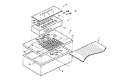
- FIG. shows schematic structure of an inkjet recording device Exploded perspective view showing schematic configuration of inkjet head Partial rear view of the head chip shown in FIG. Partial sectional view of the head chip
- an inkjet ink containing at least a disperse dye, a dispersant, water, and a water-soluble organic solvent is ejected from an inkjet head to dye a fiber.
- the ink used in the inkjet dyeing method of the present invention contains at least a disperse dye, a dispersant, water, and a water-soluble organic solvent.
- Disperse dye The ink used in the inkjet dyeing method of the present invention contains a disperse dye as a coloring material.
- the disperse dye is a nonionic dye having no ionic water-soluble group such as sulfonic acid or carboxy group, and has low solubility in water. Therefore, it is finely powdered, and is usually dispersed in water by a dispersant and blended in the ink.
- disperse dyes are soluble in organic solvents such as acetone and dimethylformamide. Moreover, it is possible to diffuse and color in a synthetic fiber in a molecular form. Inks containing disperse dyes are used for dyeing synthetic fibers, for example.
- preferable disperse dyes are shown below. However, it is not limited to the compound illustrated to these.
- the dyeing process when the dye is colored by high-temperature treatment, it is preferable to select a disperse dye having good sublimation fastness because the dye does not cause contamination by sublimation on a white background of a machine or fabric.
- the content of the disperse dye in the ink is preferably 0.1 to 20% by mass, and more preferably 0.2 to 13% by mass.
- the disperse dye may be used as a commercial product, but it is preferable to carry out a purification treatment.
- a purification method a known recrystallization method, washing or the like can be used.
- the organic solvent used in the purification method and purification treatment is preferably selected as appropriate according to the type of dye.
- the particle diameter of the disperse dye is preferably 300 nm or less as a volume average particle diameter and 900 nm or less as a maximum particle diameter.
- the volume average particle size can be determined by a commercially available particle size measuring device using a light scattering method, an electrophoresis method, a laser Doppler method, or the like. Examples include sizer 1000.
- the ratio of the number of disperse dye particles having a particle diameter of 5 ⁇ m or more to the total number of disperse dye particles contained in the ink is preferably 5% or less, and more preferably 1% or less. Furthermore, the ratio of the number of disperse dye particles having a particle diameter of 2 ⁇ m or more to the total number of disperse dye particles contained in the ink is preferably 5% or less, and more preferably 1% or less.
- the number ratio of disperse dye particles having a particle diameter of 5 ⁇ m or more was measured by measuring the total number of disperse dye particles and the number of disperse dye particles having a particle diameter of 5 ⁇ m or more using an in-liquid particle counter (for example, HIAC-8000A manufactured by Hach Company). Then, it can be obtained from the ratio.
- an in-liquid particle counter for example, HIAC-8000A manufactured by Hach Company.
- the dispersant contained in the ink used in the ink jet dyeing method of the present invention is preferably a polymer dispersant, a low molecular surfactant or the like.
- polymer dispersants include natural rubbers such as gum arabic and tragacanth, glucosides such as saponin, cellulose derivatives such as methylcellulose, carboxycellulose and hydroxymethylcellulose, natural polymers such as lignin sulfonate and shellac, poly Anionic polymers such as acrylates, styrene-acrylic acid copolymer salts, vinyl naphthalene-maleic acid copolymer salts, sodium salts of ⁇ -naphthalene sulfonic acid formalin condensate, phosphates, and polyvinyl alcohol And nonionic polymers such as polyvinylpyrrolidone and polyethylene glycol.
- the dispersant is preferably a dispersant having a carboxyl group, and these dispersants are available as commercial products, such as lignin sulfonate (for example, Vanillex RN, manufactured by Nippon Paper Industries Co., Ltd.), ⁇ - Examples thereof include polymer dispersants such as copolymers of olefin and maleic anhydride (for example, Florene G-700, manufactured by Kyoeisha Chemical Co., Ltd.) and Sanquis (manufactured by Nippon Paper Industries Co., Ltd.).
- lignin sulfonate for example, Vanillex RN, manufactured by Nippon Paper Industries Co., Ltd.
- polymer dispersants such as copolymers of olefin and maleic anhydride (for example, Florene G-700, manufactured by Kyoeisha Chemical Co., Ltd.) and Sanquis (manufactured by Nippon Paper Industries Co., Ltd.).
- the content of the dispersant including the polymer dispersant is preferably 20 to 200% by mass with respect to the disperse dye. If the amount of the dispersing agent is small, the ability to make the dispersed dyes into fine particles and the dispersion stability become insufficient. Conversely, if the content of the dispersing agent is large, the formation of fine particles and the dispersion stability are inferior, and the ink viscosity is undesirably increased. These dispersants may be used alone or in combination.
- the dispersant is preferably a dispersant in which the ratio of the number of moles of carboxyl groups is 50 mol% or more with respect to the total number of acidic dissociable groups in the dispersant, and more preferably the ratio of moles of carboxyl groups is 80 mol% or more. More preferably, the ratio of the number of moles of carboxyl groups is 80 mol% or more and 100 mol% or less.
- the acidic dissociable group possessed by the dispersant in the present invention is also called a proton dissociable group, and examples thereof include a carboxyl group, a sulfo group, a sulfato group, a phosphono group, an alkylsulfonylcarbamoyl group, an acylcarbamoyl group, and an acylsulfamoyl group. Groups, alkylsulfonylsulfamoyl groups, and the like.
- Low molecular surfactants as dispersants include, for example, anionic surfactants such as fatty acid salts, higher alcohol sulfates, liquid fatty acid sulfates, alkylallyl sulfonates, polyoxyethylene alkyl ethers, sorbitan alkyls.
- Nonionic surfactants such as esters and polyoxyethylene sorbitan alkyl esters are exemplified. Each of these compounds can be used by selecting one or two or more appropriately.
- the content of the low molecular surfactant as a dispersant is preferably in the range of 1 to 20% by mass with respect to the total mass of the ink.
- Water-soluble organic solvent examples of the water-soluble organic solvent contained in the ink used in the inkjet dyeing method of the present invention include polyhydric alcohols (for example, ethylene glycol, glycerin, 2-ethyl-2- (hydroxymethyl) -1 , 3-propanediol, tetraethylene glycol, triethylene glycol, tripropylene glycol, 1,2,4-butanetriol, diethylene glycol, propylene glycol, dipropylene glycol, butylene glycol, 1,6-hexanediol, 1,2- Hexanediol, 1,5-pentanediol, 1,2-pentanediol, 2,2-dimethyl-1,3-propanediol, 2-methyl-2,4-pentanediol, 3-methyl-1,5-pentane Diol, 3-methyl-1,3-butanediol, 2-methyl-1,3-propanediol, etc.), (
- Water contained in the ink used in the inkjet dyeing method of the present invention may be ion exchange water.
- the amount of water relative to the total ink mass is usually 20% by mass or more and less than 60% by mass, but is not particularly limited.
- the ink used in the inkjet dyeing method of the present invention may contain other optional components such as surfactants, inorganic salts, preservatives, antifungal agents, and dyeing aids.
- any of cationic, anionic, amphoteric and nonionic can be used.
- the cationic surfactant include aliphatic amine salts, aliphatic quaternary ammonium salts, benzalkonium salts, benzethonium chloride, pyridinium salts, imidazolinium salts, and the like.
- Anionic surfactants include fatty acid soap, N-acyl-N-methylglycine salt, N-acyl-N-methyl- ⁇ -alanine salt, N-acyl glutamate, alkyl ether carboxylate, acylated peptide , Alkyl sulfonate, alkyl benzene sulfonate, alkyl naphthalene sulfonate, dialkyl sulfosuccinate, alkyl sulfoacetate, ⁇ -olefin sulfonate, N-acylmethyl taurine, sulfated oil, higher alcohol sulfate Salts, secondary higher alcohol sulfates, alkyl ether sulfates, secondary higher alcohol ethoxy sulfates, polyoxyethylene alkylphenyl ether sulfates, monoglyculates, fatty acid alkylolamide sulfates, alkyl ether phosphates Salt, alkyl
- amphoteric surfactants include carboxybetaine type, sulfobetaine type, aminocarboxylate, imidazolinium betaine and the like.
- Nonionic surfactants include polyoxyethylene alkyl ether, polyoxyethylene secondary alcohol ether, polyoxyethylene alkylphenyl ether (eg, Emulgen 911), polyoxyethylene sterol ether, polyoxyethylene lanolin derivative, polyoxy Ethylene polyoxypropylene alkyl ether (for example, Newpol PE-62), polyoxyethylene glycerin fatty acid ester, polyoxyethylene castor oil, hydrogenated castor oil, polyoxyethylene sorbitan fatty acid ester, polyoxyethylene sorbitol fatty acid ester, polyethylene glycol fatty acid Esters, fatty acid monoglycerides, polyglycerol fatty acid esters, sorbitan fatty acid esters, propylene glycol fatty acid esters , Sucrose fatty acid esters, fatty acid alkanolamides,
- these surfactants When used, they can be used alone or in combination of two or more, and are added in the range of 0.001 to 3.0% by mass with respect to the total amount of the ink.
- a nonionic surfactant or an anionic surfactant is preferred, and particularly preferred is sodium dodecylbenzenesulfonate, sodium 2-ethylhexylsulfosuccinate, sodium alkylnaphthalenesulfonate, and ethylene oxide addition of phenol.
- the product is an ethylene oxide adduct of acetylenediol.
- an inorganic salt may be added to the ink.
- inorganic salts include sodium chloride, sodium sulfate, magnesium chloride, magnesium sulfide and the like. When implementing this invention, it is not limited to these.
- an antiseptic and an antifungal agent may be added to the ink.
- antiseptics and antifungal agents include aromatic halogen compounds (eg, Preventol CMK), methylene dithiocyanate, halogen-containing nitrogen sulfur compounds, 1,2-benzisothiazolin-3-one (eg, PROXEL GXL), and the like. .
- aromatic halogen compounds eg, Preventol CMK
- methylene dithiocyanate eg, methylene dithiocyanate
- halogen-containing nitrogen sulfur compounds eg, 1,2-benzisothiazolin-3-one (eg, PROXEL GXL), and the like.
- PROXEL GXL 1,2-benzisothiazolin-3-one
- the thixotropic index of the ink used in the inkjet dyeing method of the present invention is preferably 1.2 or less, and more preferably 1.1 or less.
- the thixotropic index means a ratio “viscosity value A / viscosity value B” between the viscosity value A at a shear rate of 100 / sec and the viscosity value B at a shear rate of 1000 / sec.
- the viscosity value A and the viscosity value B can each be measured at a measurement temperature of 25 ° C. using a rotary rheometer (for example, MCR-300 manufactured by Anton Paar).
- FIG. 1 is a schematic configuration diagram illustrating an example of an inkjet recording apparatus including an inkjet head.
- the inkjet recording apparatus 100 includes a conveyance roller pair 201 of a conveyance mechanism 200 that sandwiches the recording medium P. Further, the ink jet recording apparatus 100 includes a transport roller 203 that is rotationally driven by a transport motor 202. The recording medium P is transported in the Y direction (sub-scanning direction) by a pair of transport rollers 201 and a transport roller 203.
- the ink jet recording apparatus 100 includes an ink jet head H disposed between the transport roller 203 and the transport roller pair 201 so as to face the recording surface PS of the recording medium P.
- the inkjet head H is mounted and mounted on the carriage 400 so that the nozzle surface side faces the recording surface PS of the recording medium P.
- the carriage 400 is illustrated along the guide rail 300 spanned across the width direction of the recording medium P by a driving unit (not illustrated) that is substantially orthogonal to the conveyance direction (sub-scanning direction) of the recording medium P. It is provided so that it can reciprocate in the 'direction (main scanning direction).
- the inkjet head H is electrically connected to the drive device 500 via an FPC (flexible printed circuit board) 4.
- the inkjet head H scans and moves the recording surface PS of the recording medium P in the X-X ′ direction in the drawing as the carriage 400 moves in the main scanning direction.
- a desired image is recorded by ejecting droplets from the nozzles during the scanning movement.
- FIG. 2 to 4 show examples of the inkjet head H that is preferably used.
- 2 is an exploded perspective view of the inkjet head
- FIG. 3 is a partial rear view of the head chip
- FIG. 4 is a partial cross-sectional view of the head chip.
- 2 to 4 include a so-called harmonica type head chip 1, a nozzle plate 2, a wiring board 3, an FPC 4, and an ink manifold 5.
- the head chip 1 has a hexahedral shape and has two channel rows (rows A and B) in which a plurality of channels are arranged.
- the channel row of the head chip 1 drive channels 11 that discharge ink as pressure chambers and dummy channels 12 that do not discharge ink are alternately arranged.
- the head chip 1 is an independent drive type head chip that performs recording by ejecting ink only from the drive channel 11.
- the driving channel arranged in the A column of the two channel columns is 11A
- the dummy channel arranged in the A column is 12A
- the drive channel arranged in the B column of the two channel columns is referred to as 11B
- the dummy channel arranged in the B column is referred to as 12B.
- each channel row (A row or B row)
- drive channels (11A, 11B) and dummy channels (12A, 12B) are alternately arranged.
- the partition wall 13 between the drive channel (11A, 11B) and the dummy channel (12A, 12B) adjacent to each other serves as a pressure applying unit made of a piezoelectric element such as PZT.
- the A-row partition walls may be referred to as 13A
- the B-row partition walls may be referred to as 13B.
- Each drive channel (11A, 11B) and each dummy channel (12A, 12B) are opened to the front end face 1a and the rear end face 1b of the head chip 1, respectively.
- the end surface of the head chip 1 on the ink ejection side is referred to as “front end surface 1 a”, and the opposite end surface is referred to as “rear end surface 1 b”.
- the drive electrode 14 is formed in close contact with the inner surface of each channel (11A, 11B, 12A, 12B).
- the outlet of each channel is provided on the front end face 1 a of the head chip 1, and the inlet is provided on the rear end face 1 b of the head chip 1.
- Each channel is formed in a straight shape from the inlet to the outlet.
- connection electrodes (15A, 15B) are formed on the rear end surface 1b of the head chip 1.
- One end of the connection electrode (15A, 15B) is electrically connected to the drive electrode in the corresponding drive channel 11A, 11B or dummy channel 12A, 12B.
- the connection electrode 15A extends from the inside of each channel 11A, 12A to one end edge 1c of the head chip 1.
- the connection electrode 15B extends from the inside of each channel 11B, 12B toward the A column side, and extends to the front of the channel column of the A column.
- both of the connection electrodes 15A and 15B extend in the same direction from the respective channels (11A, 11B, 12A, and 12B).
- the nozzle plate 2 is bonded to the front end surface 1a of the head chip 1 with an adhesive.
- nozzles 21 are opened only at positions corresponding to the respective drive channels 11A and 11B.
- the wiring substrate 3 is a flat substrate larger than the rear end surface 1 b of the head chip 1.
- Through holes 32 ⁇ / b> A and 32 ⁇ / b> B are individually provided in a bonding region (region indicated by a one-dot chain line in FIG. 2) 31 of the wiring substrate 3 that is bonded to the rear end surface 1 b of the head chip 1.
- the positions of the through holes 32A and 32B correspond to the drive channels 11A and 11B opened on the rear end surface 1b of the head chip 1.
- Ink is supplied into the drive channels (11A, 11B) from the common ink chamber 51 of the ink manifold 5 through the through holes 32A, 32B.
- the common ink chamber 51 is configured by an internal space of a box-type ink manifold 5 that is bonded to the back side of the wiring board 3 (the side opposite to the head chip 1).
- the ink in the common ink chamber 51 is supplied to the drive channels 11A and 11B through the through holes 32A and 32B. Accordingly, the drive channels 11A and 11B communicate with each other via the common ink chamber 51. Further, the dummy channels 12 ⁇ / b> A and 12 ⁇ / b> B are blocked by the wiring substrate 3 and do not communicate with the common ink chamber 51.
- wiring electrodes 33A and 33B are formed which are electrically connected to the connection electrodes 15A and 15B arranged on the rear end surface 1b of the head chip 1.
- the wiring electrodes 33 ⁇ / b> A and 33 ⁇ / b> B extend in a direction orthogonal to the channel columns (A column and B column) of the head chip 1 on the surface of the wiring substrate 3.
- the wiring electrodes 33A and 33B are arranged alternately.
- the wiring electrodes 33A and 33B are formed by vapor deposition or sputtering.
- One end of the wiring electrode 33A corresponding to the connection electrode 15A drawn from the channels 11A and 12A arranged in the A row is located in the vicinity corresponding to each channel 11A, 12A in the A row in the bonding region 31.
- the wiring electrode 33 ⁇ / b> A extends from the bonding region 31 in a direction orthogonal to the channel row of the head chip 1 and extends to the end 3 a of the wiring substrate 3.
- one end of the wiring electrode 33B corresponding to the connection electrode 15B drawn from the channels 11B and 12B arranged in the B row is located in the vicinity corresponding to the channels 11B and 12B in the B row in the bonding region 31. Further, the wiring electrode 33B extends in the same direction as the wiring electrode 33A, and extends to the end portion 3a of the wiring substrate 3 through between the adjacent through holes 32A in the A row.
- the wiring board 3 is bonded to the rear end surface 1b of the head chip 1, and the connection electrodes (15A, 15B) of the head chip 1 and the wiring electrodes (33A, 33B) of the wiring board 3 are electrically connected correspondingly. .
- the wiring board 3 and the head chip 1 are bonded with a predetermined pressing force (for example, 1 MPa or more) by an adhesive.
- the adhesive used may be an anisotropic conductive adhesive containing conductive particles, but is preferably an adhesive containing no conductive particles in order to increase the reliability of prevention of short circuit.
- the inkjet head H is mounted on the carriage 400 of the inkjet recording apparatus 100 such that the column direction of the channel rows (A row and B row) is along the Y direction in FIG.
- the inkjet head H is electrically connected to the driving device 500 via the FPC 4 (see FIG. 1).
- a drive signal corresponding to the image data transmitted from the drive circuit in the drive device 500 is applied to the drive electrode 14 of each drive channel 11 via the FPC 4, the partition wall 13 is sheared and deformed. The volume is changed, and pressure for ejection is applied to the ink in the drive channel 11.
- FIG. 5 shows an example of a drive signal given to the inkjet head H in order to eject ink from the nozzles 21 of the inkjet head H.
- This drive signal is a rectangular wave composed of a positive voltage (+ V) having a pulse width PW, and generates a negative pressure in the channel.
- FIG. 6 shows one drive channel 11, two dummy channels 12 arranged on both sides thereof, and two partition walls 13 between them in one channel row of the inkjet head H.
- the pulse width PW which is the duration of the positive voltage of the drive signal, is set to the timing at which the pressure in the drive channel 11 changes from “negative to positive” and “from positive to negative. It is preferable to approximate the time difference (1AL) from the turning timing, and specifically, it is preferable to be in the range of 0.8 AL to 1.2 AL.
- the AL indicating the duration of the drive signal refers to 1 ⁇ 2 of the acoustic resonance period of the pressure wave in the dummy channel 12.
- AL measures the velocity of a droplet discharged when a rectangular wave driving signal is applied to the driving electrode 14 and changes the rectangular wave pulse width PW while keeping the rectangular wave voltage value constant. It is determined as the pulse width that maximizes the droplet flight speed.
- a pulse is a rectangular wave with a constant voltage peak value.
- the pulse width PW is the time difference between the timing when the voltage rises from 0V to 10% and the timing when the voltage rises from the peak value voltage to 10% when 0V is 0% and the peak value voltage is 100%. Define.
- both the time until the voltage rises from 10% to 90% and the time until the voltage falls from 90% to 10% are within 1/2 of AL, preferably 1/4.
- the driving device 500 divides all the channel rows of the inkjet head H into N (N is an integer of 2 or more) driving groups and drives each independently.
- a drive signal from the drive device 500 is applied to the drive channels of the channel row belonging to one drive group within the drive cycle T of the inkjet head H at the same timing.
- Multiple drive trains may belong to one drive group.
- Each drive channel 11 and each dummy channel 12 included in one channel row are necessarily included in the same drive group.
- the inkjet head H shown in FIG. 2 has two channel rows.
- N 2
- the channel column of the A column is the drive group A
- the channel column of the B column is the drive group B. That is, all the channel rows of the inkjet head H are divided into two drive groups.
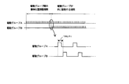
- nAL + t a phase difference “nAL + t” is given.
- a drive signal is applied in the drive cycle T of the drive group A, and the drive group A is driven before the drive group B.
- n is an integer of 1 or more
- AL is 1 ⁇ 2 of the acoustic resonance period of the pressure wave in the drive channel 11 as described above.
- t is the pressure wave transmission time obtained by “the distance between nozzles between drive groups” / “the speed at which sound is transmitted through ink”.
- the “inter-nozzle distance between drive groups” between drive groups means between two drive groups to be driven with a phase difference.
- the “distance between nozzles between drive groups” is the distance indicated by D in FIG.
- the speed C at which sound is transmitted through the ink can be calculated by the following formula. This speed C is a value unique to ink.
- K is the volume modulus of the ink
- ⁇ is the density of the ink
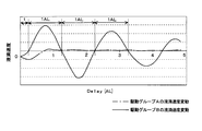
- the drive channel 11 A of the drive group A and the drive channel 11 B of the drive group B communicate with each other via the common ink chamber 51. Therefore, when a drive signal is applied to the drive electrode 14 of the drive channel 11A of the drive group A and the drive electrode 14 of the drive channel 11B of the drive group B to discharge the droplets, the droplets are affected by the influence of crosstalk. The speed may vary greatly. However, according to an experiment by the present inventor, for example, an inkjet head is configured such that droplets are ejected from the drive channel 11A of the drive group A and then ejected from the drive channel 11B of the drive group B after a predetermined delay time has elapsed. When H is driven, the droplet velocity ejected from the drive channel 11B of the drive group B periodically fluctuates according to the delay time with respect to the droplet velocity ejected from the drive channel 11A of the drive group A. Was found.
- the droplet velocity discharged from the drive channel 11B repeatedly reverses positively or negatively every 1 AL after the “time lag” from the droplet discharge time of the drive group A.
- the droplet velocity from the drive channel 11B of the drive group B becomes substantially the same as the droplet velocity from the drive channel 11A of the drive group A.
- the “time lag” from the time of droplet discharge of the drive group A corresponds to the above “time t”.
- the droplet velocity from the drive channel 11B of the drive group B after the lapse of nAL + t from the time of droplet discharge from the drive channel 11A of the drive group A is substantially equal to the droplet velocity from the drive channel 11A of the drive group A. It turns out that it becomes the same speed.
- phase difference nAL + t is given between the drive signal applied to the drive group A and the drive signal applied to the drive group B, so that the head structure of the inkjet head H is not changed at all.
- the influence of crosstalk between the drive group A and the drive group B sharing the ink chamber 51 can be substantially ignored. That is, it is possible to suppress fluctuations in the droplet velocity between the channel rows.
- a phase difference is given between the drive signal of the drive group A and the drive signal of the drive group B, the drive load is also suppressed.
- n may be an integer of 1 or more.
- an inkjet head having a plurality of channel rows discharges droplets from the nozzles in advance at different timings in order to adjust the displacement of the landing position due to the difference in physical nozzle positions between adjacent channel rows.
- the first row for example, the drive group A
- the second row drive group B
- the second row starts to discharge.
- each drive channel 11 normally discharges at the same drive timing, and only the start time and end time differ for each channel row.
- the phase difference nAL + t between the drive groups in the present invention is the difference between the start time and the end time (the landing position adjustment period between the drive groups) due to the landing position adjustment due to the difference in physical nozzle position between the drive groups.
- Delay time not included. That is, as shown in FIG. 10, the delay time provided in the period in which the two drive groups to which the phase difference is applied is driven together is shown. That is, the phase difference nAL + t is given to the application timing of the drive signal between the different drive groups A and B during the period in which the two drive groups are driven together. Thereby, the timing itself at which the droplets are ejected is different.
- the channel row of the inkjet head may be a plurality of rows.
- the plurality of channel rows can be divided into N drive groups (N is an integer of 2 or more) and driven in the same manner as described above.
- FIG. 11 shows the case where the inkjet head has four channel rows; the four channel rows are divided into two drive groups (drive group B with drive group A). Drive groups A and drive groups B are alternately arranged so that adjacent channel columns belong to different drive groups.
- D ′ is equal to D or large enough that the pressure wave is sufficiently attenuated.
- inter-nozzle distance between drive groups is defined as D.
- FIG. 13 shows the case where the inkjet head has six channel rows; all six channel rows are divided into three drive groups (drive group A, drive group B, and drive group C). Yes. Adjacent channel columns are arranged in the order of drive groups A, B, C, A, B, and C so as to belong to different drive groups.
- D ' is preferably equal to D or large enough to sufficiently attenuate the pressure wave.
- inter-nozzle distance between drive groups is defined as D.
- the channel row is divided into three or more drive groups, it is preferable from the viewpoint of avoiding a decrease in print speed that all of the n in the phase difference nAL + t between the drive groups have the same value.
- the drive groups of adjacent channel columns are different from each other. If at least one channel row belonging to a different drive group is arranged between channel rows belonging to the same drive group, the separation distance of the same drive group becomes large, so that the influence of crosstalk between the same drive groups is increased. Reduce.
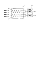
- the driving device 500 may include two or more driving circuits, and the channel strings of the respective driving groups may be driven by the two or more driving circuits. In this case, it is preferable that the channel columns driven by one drive circuit belong to different drive groups.
- FIG. 15 shows an example in which four channel rows of the inkjet head H are driven by two drive circuits (a drive circuit 501 and a drive circuit 502) in the drive device 500, two by two.
- the two channel columns driven by the drive circuit 501 belong to different drive groups (A and B).
- the two channel columns driven by the drive circuit 502 belong to different drive groups (A and B).
- the drive signal in order to generate a negative pressure in the dummy channel 12, is a rectangular wave composed of a positive voltage (+ V) with a pulse width PW, but the drive signal is not limited to this. Any drive signal may be used as long as it is a drive signal for discharging droplets.
- the head chip 1 of the inkjet head H is a so-called “harmonic type head chip” having a hexagonal shape arranged on the end faces where the inlet and outlet of the channel are opposite to each other.
- the entrances of the drive channels 11 of all the channel rows are arranged on the rear end face 1 b, and the common ink chamber 51 is arranged on the entrance side of the drive channels 11.
- the configuration of the present invention is a preferable aspect because a remarkable effect can be easily obtained.
- the head chip structure in the present invention is not necessarily limited to such a structure, and any pressure chamber may be used as long as the pressure chambers between the plurality of pressure chambers communicate with each other through a common ink chamber.
- the ink jet recording apparatus is not limited to one that performs recording by discharging droplets in the process of scanning and moving the ink jet head H in the width direction (main scanning direction) of the recording medium P (see FIG. 1).
- the inkjet head H is constituted by a line-shaped inkjet head fixed across the width direction of the recording medium P, and in the process of moving the recording medium P along the Y direction in FIG. The recording may be performed by discharging.
- the channel rows of the inkjet head H are arranged along the X-X ′ direction in FIG.
- the fiber dyed by the dyeing method of the present invention is not particularly limited as long as it is a fiber that can be dyed with a disperse dye, but among these, fibers such as polyester, acetate, and triacetate are preferable. Among these, polyester fiber is particularly preferable.
- the fiber to be dyed may be a fabric.
- the fabric may have any form such as a woven fabric, a knitted fabric, or a non-woven fabric.
- the fabric has 100% of fibers that can be dyed with disperse dyes.
- blended woven fabrics or blended nonwoven fabrics of rayon, cotton, polyurethane, acrylic, nylon, wool, silk, etc. are also used for printing. It can be used as a fabric.
- the thickness of the yarn constituting the fabric as described above is preferably in the range of 10 to 100d.
- stained by a high temperature steaming method contains the dyeing adjuvant.
- the dyeing aid forms an eutectic mixture with the water condensed in the form of cloth when the printing cloth is steamed, and has the effect of reducing the amount of moisture that re-evaporates and shortening the heating time. Further, this eutectic mixture has the effect of dissolving the dye on the fiber and promoting the diffusion rate of the dye into the fiber.
- An example of the dyeing aid is urea.
- the inkjet dyeing method of the present invention may be printing (inkjet printing).
- natural impurities oil, fat, wax, pectin, natural pigment, etc.
- water-soluble polymers such as glue
- cleaning agents used for cleaning alkalis such as sodium hydroxide and sodium carbonate, surfactants such as anionic surfactants and nonionic surfactants, enzymes and the like are used.
- the inkjet dyeing method of the present invention it is preferable to apply a pretreatment agent by a pad method, a coating method, a spray method or the like for the effect of preventing bleeding (pretreatment step). Thereafter, an image is formed on the fiber that can be dyed with a disperse dye by the ink jet recording method using the ink described above (ink application process), and then the fabric to which the ink is applied is heat-treated (coloring process). ) Further, by washing the heat-treated fabric (washing step), the printing on the fabric is completed, and a dyed product (printed product) is obtained.
- a method suitable for the fiber material or ink may be appropriately selected from known methods such as treating the water-soluble polymer into fibers, and is not particularly limited.
- a fiber provided with 0.2 to 50% by mass of at least one substance selected from the group consisting of a water-soluble metal salt, a polycation compound, a water-soluble polymer, a surfactant and a water repellent, A high degree of blur prevention is possible, and a high-definition image can be printed on a fabric, which is preferable.
- Examples of specific water-soluble polymers used for pretreatment include starches such as corn and wheat, cellulose derivatives such as carboxymethylcellulose, methylcellulose, and hydroxyethylcellulose, sodium alginate, guar gum, tamarind gum, locust bean gum And polysaccharides such as gum arabic, protein substances such as gelatin, casein and keratin, polyvinyl alcohol, polyvinyl pyrrolidone as synthetic water-soluble polymers, and acrylic acid polymers.
- Examples of the surfactant used for the pretreatment include anionic, cationic, amphoteric and nonionic ones.
- higher alcohol sulfates as anionic surfactants, sulfonates of naphthalene derivatives, etc .; quaternary ammonium salts as cationic surfactants, etc .; imidazoline derivatives as amphoteric surfactants And the like; and polyoxyethylene alkyl ethers, polyoxyethylene propylene block polymers, sorbitan fatty acid esters, polyoxyethylene sorbitan fatty acid esters, ethylene oxide adducts of acetylene alcohol, and the like as nonionic surfactants.
- examples of the water repellent include silicon, fluorine-based and wax-based ones.
- These water-soluble polymers and surfactants previously imparted to the fabric do not cause dirt due to tarring when ink-jet printing and color development at high temperatures, and are therefore stable to high-temperature environments. preferable. Further, these water-soluble polymers and surfactants that are previously imparted to the fabric are preferably those that can be easily removed from the fabric by a washing treatment after ink-jet printing and color development at a high temperature.
- ink jet textile printing method for printing on a fabric it is desirable to wind up the fabric printed after ink ejection, to develop color by heating, and to wash and dry the fabric.
- ink-jet textile printing ink is not satisfactorily dyed simply by leaving the ink printed on the fabric.
- the fabric comes out endlessly, so that the fabric printed on the floor is not only unoccupied but also unsafe, and unexpectedly dirty. May end up. Therefore, it is necessary to perform a winding operation after printing. During this operation, a medium not related to printing, such as paper, cloth, or vinyl, may be sandwiched between the cloth and the cloth. However, it is not always necessary to wind up when cutting in the middle or for a short fabric.
- the color development step is a step of developing the original hue of ink by adhering and adhering to the fabric the dye in the ink that has only adhered to the fabric surface after printing and is not sufficiently adsorbed and fixed to the fabric.
- the coloring method steaming by steam, baking by dry heat, thermosol, HT steamer by superheated steam, HP steamer by pressurized steam, etc. are used. They are appropriately selected depending on the material to be printed, ink, and the like. Further, the printed fabric may be immediately heat-treated or may be heat-treated after a while and may be dried and colored according to the intended use, and any method may be used in the present invention.
- the compound used as a carrier is preferably a compound having characteristics such as large dyeing acceleration, simple use, stable, low burden on human body and environment, easy removal from the fiber, and no influence on dye fastness.
- the carrier include o-phenylphenol, p-phenylphenol, methylnaphthalene, alkyl benzoate, alkyl salicylate, chlorobenzene, diphenyl such as diphenyl, ethers, organic acids, hydrocarbons and the like. These promote the swelling and plasticization of difficult-to-dye fibers that are difficult to dye at temperatures around 100 ° C. like polyester, and make it easier for disperse dyes to enter the fibers.
- the carrier may be preliminarily adsorbed on the fibers of the fabric used for inkjet printing, or may be included in the inkjet printing ink.
- the method is selected depending on the material and ink to be printed. For example, in the case of polyester, the treatment is generally performed with a mixed solution of caustic soda, a surfactant, and hydrosulfite. The method is usually carried out in a continuous type such as an open soaper or a batch type using a liquid dyeing machine, and any method may be used in the present invention.
- washed fabric is squeezed or dehydrated, it is dried or dried using a dryer, heat roll, iron or the like.
- Example 1 ⁇ Preparation of ink> (Preparation of dye dispersions A1-A4, B1-B4, C1, D1, E1-E4, F1, G1)
- a mixed liquid obtained by sequentially mixing the following additives was dispersed using a sand grinder to prepare a dye dispersion.
- the amount of coarse particles in a liquid particle counter HIAC-8000A manufactured by Hach Company
- the dispersion treatment was terminated when a predetermined ratio was reached.
- Dye (types listed in Table 1) 25 parts 30 parts glycerin dispersant (types and amounts listed in Table 1) Amount required to make the total amount of ion-exchanged water 100 parts
- Dye dispersion 40 parts Ethylene glycol 15 parts Glycerine appropriate amount Sodium diethylhexyl sulfosuccinate Appropriate amount Proxel GXL (manufactured by AVECIA) 0.1 part Ion-exchanged water Amount required to finish the total amount to 100 parts
- the amount of glycerin was adjusted so that the viscosity of the ink was 5.7 mPa ⁇ s.
- An appropriate amount of sodium diethylhexylsulfosuccinate was added to adjust the surface tension of the ink to 41 mN / m.
- each ink prepared in a gas permeable hollow fiber membrane (Mitsubishi Rayon Co., Ltd.) is passed through, and the outer surface of the hollow fiber membrane is decompressed with a water aspirator to remove dissolved gases in the ink. did.
- the vacuum pack was filled to prevent air from entering.
- the four channel rows of this inkjet head are driven by two drive circuits as shown in FIG.
- the inks A1-A4, B1-B4, C1, D1, E1-E4, F1, and G1 have a viscosity of 5.7 mPa ⁇ s, a surface tension of 41 mN / m, and are transmitted through the ink.
- the speed of sound was 1600 m / s.
- the drive signal applied to each drive channel from the drive device was a rectangular wave consisting only of the positive voltage (+ V) shown in FIG.
- the inkjet head was mounted on the carriage of the inkjet recording apparatus shown in FIG.
- ⁇ Crosstalk> The droplets ejected from each nozzle of each drive group A and B were imaged using a camera. The droplet velocity was calculated by image processing the resulting droplet image. From the result, the average speed of each nozzle for each channel row was obtained. From the obtained average speed,
- is calculated, and the fluctuation ratio with respect to the average speed of drive group A is calculated from the calculated value ( calculated value / average speed of drive group A). ⁇ 100: unit%). The influence of crosstalk was evaluated according to the following criteria. The results are shown in Table 2. ⁇ : Less than 5% ⁇ : 5% or more and less than 10% ⁇ : 10% or more and less than 15% ⁇ : 15% or more
- inks A1 and B1 in which the ratio of coarse particles of 5 ⁇ m or more was 6%, and stable ejection was not possible.
- inks in which the ratio of coarse particles of 5 ⁇ m or more is 3% or less no nozzle missing occurred.
- inks A2 and B2 in which the ratio of coarse particles of 5 ⁇ m or more is 3% and ink C1 or C2 in which the ratio of coarse particles of 2 ⁇ m or more is 6% or 3% do not cause nozzle missing, but are not formed on the nozzle surface. A droplet adhered.
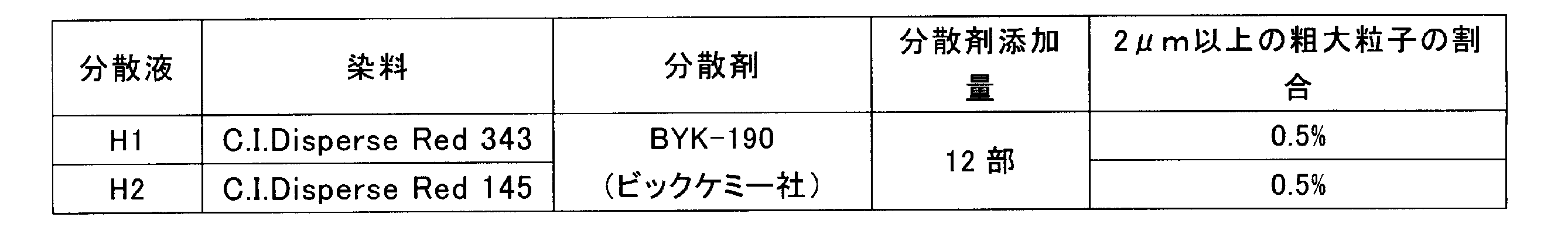
- Example 2 [Preparation of dye dispersions H1 to H2] After sequentially mixing the following additives, this mixed solution was dispersed using a sand grinder to prepare a disperse dye dispersion. At this time, during the dispersion process, the amount of coarse particles was measured using a submerged particle counter in the same manner as in Example 1, and the dispersion process was terminated when a predetermined ratio was reached.
- Disperse dye (types listed in Table 3) 25 parts 30 parts glycerin dispersant (types and amounts listed in Table 1) Amount required to make the total amount of ion-exchanged water 100 parts
- Ink H1-H2 was prepared according to the following formulation using the dye dispersion H1-H2 prepared above.
- Disperse dye dispersion 40 parts Ethylene glycol 20 parts Glycerin appropriate amount Sodium diethylhexyl sulfosuccinate Appropriate amount Proxel GXL (manufactured by AVECIA) 0.1 part Amount required to make the total amount of ion-exchanged water 100 parts
- the amount of glycerin was adjusted so that the viscosity of the ink was 10.0 mPa ⁇ s.
- An appropriate amount of sodium diethylhexylsulfosuccinate was added so that the surface tension of the ink was 32 mN / m.
- each ink prepared in a gas permeable hollow fiber membrane (Mitsubishi Rayon Co., Ltd.) is passed through, and the outer surface of the hollow fiber membrane is decompressed with a water aspirator to remove dissolved gases in the ink. did.
- the vacuum pack was filled to prevent air from entering.
- An inkjet head having two channel rows having the same structure as the inkjet head shown in FIG. 2 was prepared.
- One channel row was designated as drive group A, and the other channel row was designated as drive group B.
- the two channel rows of this inkjet head are driven by the same drive circuit.
- the viscosity of the ink H1-H2 was 10 mPa ⁇ s
- the surface tension was 32 mN / m
- the speed of sound transmitted through the ink was 1300 m / s.
- the drive signal applied from the drive device to each drive channel was a rectangular wave consisting only of the positive voltage (+ V) shown in FIG.
- the ink jet dyeing method of the present invention can improve the ink ejection stability from the ink jet head. Therefore, a high quality inkjet dyeing thing is obtained.
- H Inkjet head 1: Head chip 1a: Front end surface 1b: Rear end surface 1c: Edge 11, 11, A, 11B: Drive channel (pressure chamber) 12, 12A, 12B: Dummy channel 13, 13A, 13B: Partition wall (pressure applying means) 14: Drive electrode 15A, 15B: Connection electrode 2: Nozzle plate 21: Nozzle 3: Wiring substrate 3a: End 31: Joining region 32A, 32B: Through hole 33A, 33B: Wiring electrode 4: FPC 5: Ink manifold 51: Common ink chamber 100: Inkjet recording apparatus 200: Conveying mechanism 201: Conveying roller pair 202: Conveying motor 203: Conveying roller 300: Guide rail 400: Carriage 500: Driving device 501, 502: Driving circuit
Landscapes
- Particle Formation And Scattering Control In Inkjet Printers (AREA)
- Ink Jet (AREA)
- Ink Jet Recording Methods And Recording Media Thereof (AREA)
- Inks, Pencil-Leads, Or Crayons (AREA)
Abstract
Description
[1]少なくとも分散染料、分散剤、水および水溶性有機溶媒を含有するインクを、インクジェットヘッドから射出して繊維に記録するインクジェット染色方法であって、
前記インクに含まれる分散染料粒子の総個数に対する、粒径5μm以上の分散染料粒子の個数比率が5%以下であり、
前記インクジェットヘッドは、駆動信号の印加により動作する圧力付与手段によって内部のインクをノズルから吐出させるための圧力を発生する圧力室が配列された列を2列以上有し、前記圧力室同士は共通インク室によって連通しており、
前記圧力室が配列された列をN個(Nは2以上の整数)の駆動グループに分割し、前記駆動グループ毎に、前記圧力室の前記圧力付与手段に印加する前記駆動信号に、nAL+t(但し、nは1以上の整数、ALは圧力室における圧力波の音響的共振周期の1/2、tは「駆動グループ間のノズル間距離」/「前記インク中を音が伝わる速度」で求められる圧力波伝達時間)の位相差を与える、インクジェット染色方法。
[2]隣接する前記圧力室の列を、互いに異なる駆動グループとすることを特徴とする[1]に記載のインクジェット染色方法。
[3]前記インクのチクソトロピック指数が1.2以下である、[1]または[2]に記載のインクジェット染色方法。
本発明のインクジェット染色方法で用いられるインクは、少なくとも分散染料、分散剤、水および水溶性有機溶媒を含有する。
本発明のインクジェット染色方法で用いられるインクは、色材として分散染料を含有する。分散染料は、スルホン酸,カルボキシ基などのイオン性の水溶性基をもたない非イオン性染料で、水への溶解度が小さい。そのため微粉状とされ、通常分散剤によって水に分散されて、インク中に配合される。顔料と異なり、分散染料はアセトンやジメチルホルムアミドなどの有機溶媒に可溶である。また、合成繊維中に分子状で拡散し着色することが可能である。分散染料を含有するインクは、例えば合成繊維の染色に用いられる。
本発明のインクジェット染色方法で用いられるインクに含まれる分散剤は、高分子分散剤、低分子界面活性剤などであることが好ましい。高分子分散剤の例には、アラビアゴム、トラガントゴムなどの天然ゴム類、サポニンなどのグルコシド類、メチルセルロース、カルボキシセルロース、ヒドロキシメチルセルロースなどのセルロース誘導体、リグニンスルホン酸塩、セラックなどの天然高分子、ポリアクリル酸塩、スチレン-アクリル酸共重合物の塩、ビニルナフタレン-マレイン酸共重合物の塩、β-ナフタレンスルホン酸ホルマリン縮合物のナトリウム塩、リン酸塩などの陰イオン性高分子やポリビニルアルコール、ポリビニルピロリドン、ポリエチレングリコールなどの非イオン性高分子などが挙げられる。
本発明のインクジェット染色方法で用いられるインクに含まれる水溶性有機溶媒の例には、多価アルコール類(例えば、エチレングリコール、グリセリン、2-エチル-2-(ヒドロキシメチル)-1,3-プロパンジオール、テトラエチレングリコール、トリエチレングリコール、トリプロピレングリコール、1,2,4-ブタントリオール、ジエチレングリコール、プロピレングリコール、ジプロピレングリコール、ブチレングリコール、1,6-ヘキサンジオール、1,2-ヘキサンジオール、1,5-ペンタンジオール、1,2-ペンタンジオール、2,2-ジメチル-1,3-プロパンジオール、2-メチル-2,4-ペンタンジオール、3-メチル-1,5-ペンタンジオール、3-メチル-1,3-ブタンジオール、2-メチル-1,3-プロパンジオール等)、アミン類(例えば、エタノールアミン、2-(ジメチルアミノ)エタノール等)、一価アルコール類(例えば、メタノール、エタノール、ブタノール等)、多価アルコールのアルキルエーテル類(例えば、ジエチレングリコールモノメチルエーテル、ジエチレングリコールモノブチルエーテル、トリエチレングリコールモノメチルエーテル、トリエチレングリコールモノブチルエーテル、エチレングリコールモノメチルエーテル、エチレングリコールモノブチルエーテル、プロピレングリコールモノメチルエーテル、プロピレングリコールモノブチルエーテル、ジプロピレングリコールモノメチルエーテル等)、2,2'-チオジエタノール、アミド類(例えば、N,N-ジメチルホルムアミド等)、複素環類(2-ピロリドン等)、アセトニトリルなどが含まれる。全インク質量に対する水溶性有機溶媒量は、10~60質量%が好ましい。
本発明のインクジェット染色方法で用いられるインクに含まれる水は、イオン交換水であってもよい。全インク質量に対する水の量は、通常は20質量%以上60質量%未満であるが、特に限定されない。
本発明のインクジェット染色方法で用いられるインクには、他の任意成分、例えば界面活性剤、無機塩、防腐剤、防黴剤、染着助剤などが含まれていてもよい。
本発明のインクジェット染色方法で用いられるインクのチクソトロピック指数は、1.2以下であることが好ましく、1.1以下であることが好ましい。チクソトロピック指数とは、せん断速度100/secでの粘度値Aと、せん断速度1000/secでの粘度値Bとしたときに、両者の比「粘度値A/粘度値B」を意味する。粘度値Aおよび粘度値Bは、それぞれ測定温度25℃とし、回転式レオメータ(例えば、アントンパール社製MCR-300)を用いて測定することができる。
本発明のインクジェット染色方法は、通常、インクジェットヘッドを具備するインクジェット記録装置を用いて行われる。図1は、インクジェットヘッドを具備するインクジェット記録装置の一例を示す概略構成図である。
図5は、インクジェットヘッドHのノズル21からインクを吐出するために、インクジェットヘッドHに与えられる駆動信号の一例を示している。この駆動信号は、パルス幅PWの正電圧(+V)からなる矩形波であり、チャネル内に負の圧力を発生させる。
本発明の染色方法によって染色される繊維は、分散染料で染色可能な繊維であれば特に制限はないが、中でもポリエステル、アセテート、トリアセテート等の繊維が好ましい。その中でも、ポリエステル繊維が特に好ましい。
《インクの調製》
〔染料分散液A1-A4, B1-B4, C1, D1, E1-E4, F1, G1の調製〕
下記各添加剤を順次混合して得られた混合液を、サンドグラインダーを用いて分散処理して、染料分散液を調製した。このとき、分散処理中に、液中パーティクルカウンター(Hach Company社製 HIAC-8000A)における粗大粒子の量を測定し、所定の割合となったところで、分散処理を終了した。
グリセリン 30部
分散剤(表1に記載の種類、量)
イオン交換水 総量を100部とするのに要する量

上記調製した各染料分散液を用いて、下記の処方に準じてインクA1-A4, B1-B4, C1, D1, E1-E4, F1, G1を調製した。
エチレングリコール 15部
グリセリン 適量
ジエチルヘキシルスルホコハク酸ナトリウム 適量
プロキセルGXL(AVECIA社製) 0.1部
イオン交換水 総量を100部に仕上げるのに要する量
調製したインクA1-A4, B1-B4, C1, D1, E1-E4, F1, G1を用いて、インクジェット装置で連続射出試験を行った。
用いたヘッドの全ノズルから、インクをフルデューティにて、30分間または60分間連続射出を行い、その際にノズル欠の発生、ノズル面に付着した液滴の数を観察することで連続射出試験評価を行った。その結果を表2に示す。
◎:ノズル欠の発生無く、液滴の付着なし
○:ノズル欠の発生無く、液滴の付着5個以内
△:ノズル欠の発生無く、液滴の付着20個以内
×:ノズル欠の発生あり
各駆動グループA、Bの各ノズルからそれぞれ吐出される液滴を、カメラを用いて撮像した。得られた液滴像を画像処理することによって液滴速度を計算した。その結果からチャネル列毎の各ノズルの平均速度を求めた。得られた平均速度から、|駆動グループAの平均速度-駆動グループBの平均速度|を計算し、その計算値から駆動グループAの平均速度に対する変動比率(=計算値/駆動グループAの平均速度×100:単位%)を求めた。以下の基準に従ってクロストークの影響を評価した。その結果を表2に示す。
◎:5%未満
○:5%以上10%未満
△:10%以上15%未満
×:15%以上
インクジェットヘッドを駆動する際の駆動負荷について、nAL+t=0として全チャネル列に位相差を設けずに全駆動チャネルを駆動した際の電流値を100とし、それに対する比率(%)を求めた。駆動負荷の値は小さいほど好ましい。その結果を表2に示す。

〔染料分散液H1~H2の調製〕
下記各添加剤を順次混合した後、この混合液を、サンドグラインダーを用いて分散処理して分散染料分散液を調製した。このとき、分散処理中に実施例1と同様に、液中パーティクルカウンターを用いて粗大粒子量を測定し、所定の割合になったところで分散処理を終了した。
グリセリン 30部
分散剤(表1に記載の種類、量)
イオン交換水 総量を100部とするのに要する量
上記調製した染料分散液H1-H2を用いて、下記の処方に準じてインクH1-H2を調製した。
エチレングリコール 20部
グリセリン 適量
ジエチルヘキシルスルホコハク酸ナトリウム 適量
プロキセルGXL(AVECIA社製) 0.1部
イオン交換水 総量を100部とするのに要する量
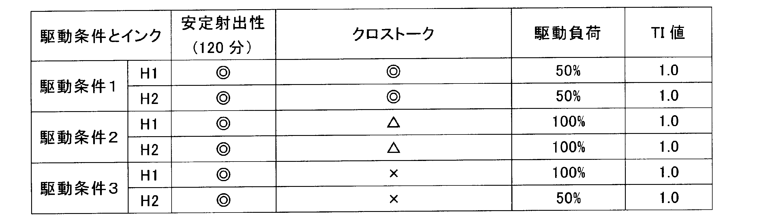
調製したインクH1-H2を用いて、インクジェット装置で連続射出試験を行った。
このインクジェットヘッドを、図1に示すインクジェット記録装置のキャリッジ上に搭載し、駆動グループA、B間の位相差(nAL+t)を、n=1とし、1×5.0+0.9=5.9μsとして、駆動グループAに先に駆動信号を印加するようにインクジェットヘッドを駆動した。
駆動条件1と同一のインクジェットヘッドにおいて、駆動グループA、B間の位相差を全く設けず、nAL+t=0として、同様に、安定射出性と、クロストークと、駆動負荷とを評価した。その結果を表4に示す。
駆動条件1と同一のインクジェットヘッドにおいて、位相差(nAL+t)をn=0.5、t=0として、0.5×5.0=2.5μsとした以外は、実施例1と同一にし、安定射出性と、クロストークと、駆動負荷とを評価した。その結果を表4に示す。
1:ヘッドチップ
1a:前端面
1b:後端面
1c:端縁
11、11A、11B:駆動チャネル(圧力室)
12、12A、12B:ダミーチャネル
13、13A、13B:隔壁(圧力付与手段)
14:駆動電極
15A、15B:接続電極
2:ノズルプレート
21:ノズル
3:配線基板
3a:端部
31:接合領域
32A、32B:貫通穴
33A、33B:配線電極
4:FPC
5:インクマニホールド
51:共通インク室
100:インクジェット記録装置
200:搬送機構
201:搬送ローラー対
202:搬送モーター
203:搬送ローラー
300:ガイドレール
400:キャリッジ
500:駆動装置
501、502:駆動回路
Claims (3)
- 少なくとも分散染料、分散剤、水および水溶性有機溶媒を含有するインクを、インクジェットヘッドから射出して繊維に記録するインクジェット染色方法であって、
前記インクに含まれる分散染料粒子の総個数に対する、粒径5μm以上の分散染料粒子の個数比率が5%以下であり、
前記インクジェットヘッドは、駆動信号の印加により動作する圧力付与手段によって内部のインクをノズルから吐出させるための圧力を発生する圧力室が配列された列を2列以上有し、前記圧力室同士は共通インク室によって連通しており、
前記圧力室が配列された列をN個(Nは2以上の整数)の駆動グループに分割し、前記駆動グループ毎に、前記圧力室の前記圧力付与手段に印加する前記駆動信号に、nAL+t(但し、nは1以上の整数、ALは圧力室における圧力波の音響的共振周期の1/2、tは「駆動グループ間のノズル間距離」/「前記インク中を音が伝わる速度」で求められる圧力波伝達時間)の位相差を与える、インクジェット染色方法。 - 隣接する前記圧力室の列を、互いに異なる駆動グループとすることを特徴とする請求項1に記載のインクジェット染色方法。
- 前記インクのチクソトロピック指数が1.2以下である、請求項1または2に記載のインクジェット染色方法。
Priority Applications (3)
| Application Number | Priority Date | Filing Date | Title |
|---|---|---|---|
| JP2015532714A JP6341206B2 (ja) | 2013-08-22 | 2014-08-22 | インクジェット染色方法 |
| CN201480046177.3A CN105473339B (zh) | 2013-08-22 | 2014-08-22 | 喷墨染色方法 |
| EP14837343.4A EP3037265B1 (en) | 2013-08-22 | 2014-08-22 | Inkjet dyeing method |
Applications Claiming Priority (2)
| Application Number | Priority Date | Filing Date | Title |
|---|---|---|---|
| JP2013-172330 | 2013-08-22 | ||
| JP2013172330 | 2013-08-22 |
Publications (1)
| Publication Number | Publication Date |
|---|---|
| WO2015025524A1 true WO2015025524A1 (ja) | 2015-02-26 |
Family
ID=52483318
Family Applications (1)
| Application Number | Title | Priority Date | Filing Date |
|---|---|---|---|
| PCT/JP2014/004333 Ceased WO2015025524A1 (ja) | 2013-08-22 | 2014-08-22 | インクジェット染色方法 |
Country Status (4)
| Country | Link |
|---|---|
| EP (1) | EP3037265B1 (ja) |
| JP (1) | JP6341206B2 (ja) |
| CN (1) | CN105473339B (ja) |
| WO (1) | WO2015025524A1 (ja) |
Cited By (4)
| Publication number | Priority date | Publication date | Assignee | Title |
|---|---|---|---|---|
| JP2016169289A (ja) * | 2015-03-12 | 2016-09-23 | コニカミノルタ株式会社 | 水系インクおよびインクジェット捺染方法 |
| JP2017056697A (ja) * | 2015-09-18 | 2017-03-23 | コニカミノルタ株式会社 | 圧電アクチュエータユニット、インクジェットヘッド、インクジェット記録装置、ヘッドチップ及び配線基板 |
| JP2020025916A (ja) * | 2018-08-10 | 2020-02-20 | 東芝テック株式会社 | 薬液吐出装置 |
| CN113215841A (zh) * | 2021-06-07 | 2021-08-06 | 广东立彩数码科技有限公司 | 一种替代传统纺织印染的数码喷墨工艺 |
Families Citing this family (4)
| Publication number | Priority date | Publication date | Assignee | Title |
|---|---|---|---|---|
| PT3118000T (pt) * | 2014-03-14 | 2019-02-06 | Konica Minolta Inc | Método de gravação por jato de tinta |
| JP6593622B2 (ja) * | 2015-03-20 | 2019-10-23 | セイコーエプソン株式会社 | 記録装置 |
| US12195633B2 (en) | 2020-02-28 | 2025-01-14 | Konica Minolta, Inc. | Ink-jet ink and method for forming image |
| JP7545643B2 (ja) * | 2021-01-20 | 2024-09-05 | 理想テクノロジーズ株式会社 | 液体吐出ヘッド |
Citations (6)
| Publication number | Priority date | Publication date | Assignee | Title |
|---|---|---|---|---|
| JP2003011368A (ja) | 2001-07-04 | 2003-01-15 | Ricoh Co Ltd | インクジェットヘッド及びインクジェット記録装置 |
| JP2007084623A (ja) * | 2005-09-20 | 2007-04-05 | Nihon Network Support:Kk | インクジェットプリンタ用インク |
| JP2007168185A (ja) | 2005-12-20 | 2007-07-05 | Konica Minolta Holdings Inc | インクジェットヘッド |
| JP2010076276A (ja) * | 2008-09-26 | 2010-04-08 | Kyocera Corp | 印刷装置および印刷方法 |
| JP2011213060A (ja) * | 2010-04-01 | 2011-10-27 | Seiko Epson Corp | インクジェット記録方法 |
| WO2014054655A1 (ja) * | 2012-10-02 | 2014-04-10 | コニカミノルタ株式会社 | インクジェットヘッドの駆動方法、インクジェットヘッドの駆動装置及びインクジェット記録装置 |
Family Cites Families (6)
| Publication number | Priority date | Publication date | Assignee | Title |
|---|---|---|---|---|
| JP2000326511A (ja) * | 1999-05-18 | 2000-11-28 | Nec Corp | インクジェット記録ヘッドの駆動方法及びその回路 |
| JP2002137388A (ja) * | 2000-11-01 | 2002-05-14 | Konica Corp | インクジェットヘッド |
| JP4247043B2 (ja) * | 2002-06-28 | 2009-04-02 | 東芝テック株式会社 | インクジェットヘッドの駆動装置 |
| JP2005255707A (ja) * | 2004-03-09 | 2005-09-22 | Konica Minolta Holdings Inc | インクジェットインク及びその製造方法並びにインクジェット記録方法 |
| JP4543847B2 (ja) * | 2004-09-14 | 2010-09-15 | ブラザー工業株式会社 | ライン式インクジェットプリンタ |
| WO2013027715A1 (ja) * | 2011-08-24 | 2013-02-28 | コニカミノルタIj株式会社 | インクジェット記録装置及びインクジェット記録方法 |
-
2014
- 2014-08-22 WO PCT/JP2014/004333 patent/WO2015025524A1/ja not_active Ceased
- 2014-08-22 JP JP2015532714A patent/JP6341206B2/ja not_active Expired - Fee Related
- 2014-08-22 CN CN201480046177.3A patent/CN105473339B/zh active Active
- 2014-08-22 EP EP14837343.4A patent/EP3037265B1/en active Active
Patent Citations (6)
| Publication number | Priority date | Publication date | Assignee | Title |
|---|---|---|---|---|
| JP2003011368A (ja) | 2001-07-04 | 2003-01-15 | Ricoh Co Ltd | インクジェットヘッド及びインクジェット記録装置 |
| JP2007084623A (ja) * | 2005-09-20 | 2007-04-05 | Nihon Network Support:Kk | インクジェットプリンタ用インク |
| JP2007168185A (ja) | 2005-12-20 | 2007-07-05 | Konica Minolta Holdings Inc | インクジェットヘッド |
| JP2010076276A (ja) * | 2008-09-26 | 2010-04-08 | Kyocera Corp | 印刷装置および印刷方法 |
| JP2011213060A (ja) * | 2010-04-01 | 2011-10-27 | Seiko Epson Corp | インクジェット記録方法 |
| WO2014054655A1 (ja) * | 2012-10-02 | 2014-04-10 | コニカミノルタ株式会社 | インクジェットヘッドの駆動方法、インクジェットヘッドの駆動装置及びインクジェット記録装置 |
Cited By (5)
| Publication number | Priority date | Publication date | Assignee | Title |
|---|---|---|---|---|
| JP2016169289A (ja) * | 2015-03-12 | 2016-09-23 | コニカミノルタ株式会社 | 水系インクおよびインクジェット捺染方法 |
| JP2017056697A (ja) * | 2015-09-18 | 2017-03-23 | コニカミノルタ株式会社 | 圧電アクチュエータユニット、インクジェットヘッド、インクジェット記録装置、ヘッドチップ及び配線基板 |
| JP2020025916A (ja) * | 2018-08-10 | 2020-02-20 | 東芝テック株式会社 | 薬液吐出装置 |
| JP7149765B2 (ja) | 2018-08-10 | 2022-10-07 | 東芝テック株式会社 | 薬液吐出装置 |
| CN113215841A (zh) * | 2021-06-07 | 2021-08-06 | 广东立彩数码科技有限公司 | 一种替代传统纺织印染的数码喷墨工艺 |
Also Published As
| Publication number | Publication date |
|---|---|
| EP3037265A4 (en) | 2018-01-10 |
| JPWO2015025524A1 (ja) | 2017-03-02 |
| EP3037265A1 (en) | 2016-06-29 |
| EP3037265B1 (en) | 2019-06-19 |
| JP6341206B2 (ja) | 2018-06-13 |
| CN105473339B (zh) | 2017-05-10 |
| CN105473339A (zh) | 2016-04-06 |
Similar Documents
| Publication | Publication Date | Title |
|---|---|---|
| JP6341206B2 (ja) | インクジェット染色方法 | |
| JP7218571B2 (ja) | 液体吐出装置、インクジェット記録方法及び顔料捺染インク組成物 | |
| JP4655585B2 (ja) | インクジェット捺染方法 | |
| US8709103B2 (en) | Sublimation transfer ink, method for producing a dyed article, and dyed article | |
| JPH09279489A (ja) | インクジェット捺染用布帛、インクジェット捺染方法および捺染物 | |
| JP6406346B2 (ja) | インクジェット記録方法 | |
| JP2005281523A (ja) | インクジェットインクの製造方法及びインクジェット記録方法 | |
| JP2020157709A (ja) | インクジェット記録装置及びインクジェット捺染方法 | |
| WO2011078068A1 (ja) | インクジェット捺染用布帛前処理剤、布帛の前処理方法及びテキスタイルプリント方法 | |
| JP2017214668A (ja) | インクジェット捺染方法 | |
| JP2004018544A (ja) | インクジェット捺染用インクとそれを用いたインクジェット捺染方法 | |
| JP4706207B2 (ja) | インクジェット捺染インクセットとその製造方法、及び該インクジェット捺染インクセットを用いたインクジェット記録方法 | |
| JP2005264021A (ja) | インクジェット用インク及びインクジェット記録方法 | |
| EP3141656B1 (en) | Inkjet printing method and inkjet printing apparatus | |
| JPH10331078A (ja) | インクジェット染色用布帛、それを用いたインクジェット染色方法およびインクジェット染色物 | |
| JPH0742428B2 (ja) | インクジェット捺染方法 | |
| JP2005263835A (ja) | インクジェット捺染インクセット及びインクジェット捺染方法 | |
| JP2005248106A (ja) | インクジェット捺染インク、インクジェット捺染インクセット及びインクジェット記録方法 | |
| JP2005263836A (ja) | インクジェット捺染インクセット、インクジェット捺染用ブラックインク及びそれを用いたインクジェット捺染方法 | |
| JP2005248105A (ja) | インクジェット捺染インク、インクジェット捺染インクセット及びインクジェット記録方法 | |
| JPS61179269A (ja) | インクジエツト記録用インク組成物 | |
| JP2014177714A (ja) | インクジェット捺染物の製造方法 | |
| JP2006008738A (ja) | インクジェット捺染インクセットとその製造法、およびそれを用いたインクジェット記録方法 | |
| JP2005263880A (ja) | インクジェットインク用水性分散液および分散系インクジェットインクの製造方法、インクジェット記録方法 | |
| JP2005263837A (ja) | インクジェット捺染インクセット、インクジェット捺染用ブラックインク及びそれを用いたインクジェット捺染方法 |
Legal Events
| Date | Code | Title | Description |
|---|---|---|---|
| WWE | Wipo information: entry into national phase |
Ref document number: 201480046177.3 Country of ref document: CN |
|
| 121 | Ep: the epo has been informed by wipo that ep was designated in this application |
Ref document number: 14837343 Country of ref document: EP Kind code of ref document: A1 |
|
| ENP | Entry into the national phase |
Ref document number: 2015532714 Country of ref document: JP Kind code of ref document: A |
|
| WWE | Wipo information: entry into national phase |
Ref document number: 2014837343 Country of ref document: EP |
|
| NENP | Non-entry into the national phase |
Ref country code: DE |