WO2015025895A1 - ステアリング装置 - Google Patents
ステアリング装置 Download PDFInfo
- Publication number
- WO2015025895A1 WO2015025895A1 PCT/JP2014/071793 JP2014071793W WO2015025895A1 WO 2015025895 A1 WO2015025895 A1 WO 2015025895A1 JP 2014071793 W JP2014071793 W JP 2014071793W WO 2015025895 A1 WO2015025895 A1 WO 2015025895A1
- Authority
- WO
- WIPO (PCT)
- Prior art keywords
- plate
- bracket
- movable bracket
- slide member
- steering
- Prior art date
- Legal status (The legal status is an assumption and is not a legal conclusion. Google has not performed a legal analysis and makes no representation as to the accuracy of the status listed.)
- Ceased
Links
Images





Classifications
-
- B—PERFORMING OPERATIONS; TRANSPORTING
- B62—LAND VEHICLES FOR TRAVELLING OTHERWISE THAN ON RAILS
- B62D—MOTOR VEHICLES; TRAILERS
- B62D1/00—Steering controls, i.e. means for initiating a change of direction of the vehicle
- B62D1/02—Steering controls, i.e. means for initiating a change of direction of the vehicle vehicle-mounted
- B62D1/16—Steering columns
- B62D1/18—Steering columns yieldable or adjustable, e.g. tiltable
- B62D1/19—Steering columns yieldable or adjustable, e.g. tiltable incorporating energy-absorbing arrangements, e.g. by being yieldable or collapsible
- B62D1/195—Yieldable supports for the steering column
Definitions
- This invention relates to a steering device.
- a secondary collision in which the driver hits the steering wheel (steering member) may occur following the primary collision at that time.
- various structures have been proposed in which a part of the steering column is detached from the vehicle body and moved in the column axial direction (front of the vehicle body) in order to absorb the impact at the time of the secondary collision.
- a notch that extends parallel to the column axis direction is provided on a vehicle body side bracket that is fixed to the vehicle body.
- a locking capsule is fitted into the locking notch, and the locking capsule is positioned with respect to the vehicle body side bracket by a plurality of locking pins.
- the column side bracket holding a steering wheel is connected with the latching capsule with the volt
- the locking capsule rubs against the peripheral edge of the locking notch in the vehicle body side bracket at the time of a secondary collision.
- this configuration can be easily used in the steering column support device. It is preferable that it can be assembled.
- the impact absorption load at the time of the secondary collision also referred to as the EA load, the impact load at the secondary collision absorbed according to the movement of the locking capsule
- the impact load at the secondary collision absorbed according to the movement of the locking capsule can be stabilized, It is preferable for promoting the impact absorption during the secondary collision.
- the present invention has been made under such a background, and improves the assembly property of a configuration that reduces friction between a pair of members that move relative to each other for absorbing a shock at the time of a secondary collision, and uses the configuration.
- An object of the present invention is to provide a steering device capable of achieving both the stabilization of the shock absorbing load at the time of the secondary collision in the case.
- a fixed bracket (23) fixed to the vehicle body (13) and an opposing surface (32A) facing the fixed bracket, and is connected to the steering member (2).
- a movable bracket (24) configured to move relative to the fixed bracket toward the downstream side in a predetermined movement direction (Z1) with a steering member, and assembled to the movable bracket
- a slide member (89) configured to move integrally with the movable bracket in a state of being interposed between the facing surface and the fixed bracket at the time of a secondary collision, It is provided across the entire area in the moving direction on the facing surface, and is inserted between the facing surface and the fixed bracket.
- a main body portion (90) configured to slidably rub, and a fastening portion which is bent from the downstream end portion (90A) in the moving direction in the main body portion and hooks on the movable bracket from the downstream side in the moving direction.
- a steering device (1) is provided.
- the movable bracket includes a plate-like portion (32) having the facing surface, and a pair of bent portions (41) bent in the same direction from both sides in the plate-like portion in a direction orthogonal to the moving direction (Y1). May be included.
- the maximum dimension (M) of the main body in the orthogonal direction may be larger than the maximum distance (N) between the pair of bent portions.
- the fastening portion is formed by bending a distal end portion of the fastening portion opposite to the body portion side toward the upstream side in the moving direction, and is disposed between the pair of bending portions, while the body portion is disposed.
- a sandwiching portion (95) that sandwiches the plate-like portion between the two may be included.
- the distance (K) between the one end edge (95A) and the other end edge (95B) of the clamping part in the orthogonal direction is the distance between the pair of bent parts (L) at the boundary between the pair of bent parts and the plate-like part. ) May be the same.
- a convex portion (100) may be provided on one of the slide member and the movable bracket.
- a concave portion (101) into which the convex portion is fitted may be provided.
- a suspension member (25) that extends from the fixed bracket and suspends the movable bracket may be included.
- the slide member may be formed with a notch (93) through which the suspension member is passed.
- a conductive friction reducing material (200) may be provided on a portion of the slide member that rubs against the fixed bracket.
- the numbers in parentheses represent reference numerals of corresponding components in the embodiments described later, but the scope of the claims is not limited by these reference numerals.
- the movable bracket moves relative to the fixed bracket toward the downstream side in the moving direction, so that the impact at the time of the secondary collision can be absorbed.
- the slide member assembled to the movable bracket moves integrally with the movable bracket while being interposed between the opposed surface of the movable bracket and the fixed bracket, the friction between the movable bracket and the fixed bracket is reduced. Can be made.
- Such a slide member includes a main body portion inserted between the opposing surface of the movable bracket and the fixed bracket, and a fastening portion bent from the downstream end portion in the movement direction in the main body portion.
- the main body is provided over the entire area in the movement direction on the facing surface of the movable bracket.
- the clasp is caught on the movable bracket from the downstream side in the moving direction. Therefore, not only can the slide member be positioned in the movement direction with respect to the movable bracket, but also at the time of a secondary collision, the slide member can always be moved integrally with the movable bracket toward the downstream side in the movement direction. And a slide member can be easily assembled
- the configuration that reduces the friction between a pair of members (between the movable bracket and the fixed bracket) that move relative to each other for absorbing a shock in a secondary collision. It is possible to achieve both the improvement of the assembly property and the stabilization of the shock absorbing load at the time of the secondary collision in the case of using the configuration.
- the slide member since the maximum dimension of the main body portion in the orthogonal direction is larger than the maximum distance between the pair of bent portions in the movable bracket, it is physically impossible to mistakenly incorporate the slide member between the pair of bent portions. It is. Therefore, the slide member can be correctly assembled to the movable bracket so that the main body portion rests on the opposing surface of the plate-like portion of the movable bracket. Therefore, the assembling property of the slide member can be improved.
- the fastening portion can be reliably hooked to the movable bracket by sandwiching the plate-like portion of the movable bracket between the holding portion formed at the distal end portion of the fastening portion and the main body portion.
- the interval between the one end edge and the other end edge of the sandwiching portion in the orthogonal direction (when the plurality of sandwiching portions are arranged in the orthogonal direction, the outer ends of the pair of sandwiching portions located at both ends in the orthogonal direction The distance between the edges is the same as the distance between the pair of bent portions at the boundary between the pair of bent portions and the plate-like portion.
- the slide member can be positioned in the orthogonal direction with respect to the movable bracket as long as the clamping portion is disposed between the pair of bent portions in the movable bracket, and the subsequent fine adjustment of the slide member (position in the orthogonal direction) is also possible. It becomes unnecessary. Therefore, the assembling property of the slide member can be improved.
- the slide member and the movable bracket can be positioned relative to each other by fitting the convex portion into the concave portion. According to the present invention, by passing the suspension member through the notch of the slide member, the slide member can be assembled to the movable bracket while avoiding interference with the suspension member.
- the sliding member provided with the conductive friction reducing material ensures the electrical conductivity between the fixed bracket and the movable bracket, and smoothly moves the movable bracket relative to the fixed bracket at the time of a secondary collision. Can be achieved.
- FIG. 1 is a schematic side view of a steering device 1 according to an embodiment of the present invention, and shows a schematic configuration of the steering device 1.
- FIG. 2 is a schematic cross-sectional view of the steering device 1 of FIG. 1, and shows a cross section taken along line II-II of FIG.
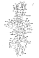
- FIG. 3 is an exploded perspective view of the steering device 1 of FIG.
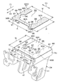
- FIG. 4 is an exploded perspective view for explaining the assembly of the movable bracket 24 and the slide member 89.
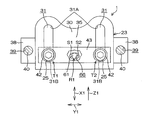
- FIG. 5 is a partially broken schematic plan view of the fixing bracket 23, the pair of suspension mechanisms T1 and T2, and the connection / release mechanism R1.
- FIG. 6 is a cross-sectional view in a state where the first plate 30 of the fixed bracket 23 and the second plate 32 of the movable bracket 24 are connected, and shows a cross-section in the front-rear direction including the axis of the pin 61.
- FIG. 7 is a cross-sectional view of the first plate 30 and the second plate 32 at the time of the secondary collision, and the second plate 32 is detached from the state of FIG. 6 to the downstream side in the predetermined movement direction Z1 due to the shearing of the pin 61. Shows the state.
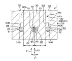
- FIG. 8 is a cross-sectional view taken along line VIII-VIII in FIG. 2 and shows a cross section of the first plate 30 and the connecting / disconnecting mechanism R1.
- FIG. 9 is a cross-sectional view taken along the line IX-IX in FIG. 2 and shows a cross section of the second plate 32 and the connecting / disconnecting mechanism R1.
- FIG. 10 is a diagram in which a modified example is applied in FIG.
- FIG. 1 is a schematic side view of a steering device 1 according to an embodiment of the present invention, and shows a schematic configuration of the steering device 1.
- the left side in FIG. 1 is the steering device 1 and the front side of the vehicle body (to which the steering device 1 is attached), and the right side in FIG. 1 is the steering device 1 and the rear side of the vehicle body.
- 1 is the upper side of the steering device 1 and the vehicle body, and the lower side in FIG. 1 is the lower side of the steering device 1 and the vehicle body.
- a steering device 1 includes a steering shaft 3 that is connected to a steering member 2 such as a steering wheel and extends in the front-rear direction, an intermediate shaft 5 that is connected to the steering shaft 3 via a universal joint 4, A pinion shaft 7 connected to the intermediate shaft 5 through a universal joint 6, a rack shaft 8, and a steering column 15 are mainly provided.
- a pinion 7A is provided near the end (lower end) of the pinion shaft 7 and meshes with the rack 8A of the rack shaft 8.
- a steering mechanism A1 is configured by a rack and pinion mechanism including the pinion shaft 7 and the rack shaft 8.
- the rack shaft 8 is supported by a housing 10 fixed to a vehicle body side member (a vehicle body itself or a member fixed to the vehicle body, the same applies hereinafter) 9.
- the rack shaft 8 is movable in the vehicle width direction that is the width direction of the vehicle (the direction orthogonal to the paper surface).
- Each end of the rack shaft 8 is connected to steered wheels (wheels) via tie rods and knuckle arms (not shown).
- the steering shaft 3 includes, for example, an upper shaft 11 and a lower shaft 12 that are connected so as to be able to rotate together and to be relatively movable in the axial direction X1, using spline coupling, for example.
- the steering shaft 3 is rotatably supported by a steering column 15 fixed to the vehicle body side members 13 and 14 via bearings (upper bearing 75 and lower bearing 76).
- the steering column 15 includes a cylindrical upper jacket 16 and a lower jacket 17 that are fitted so as to be relatively movable in the axial direction X1 of the steering shaft 3, and a housing 18 that is connected to one end (lower end) of the lower jacket 17 in the axial direction X1. And.
- a midway portion between a front end portion (also a lower end portion) and a rear end portion (also an upper end portion) is accommodated in the steering column 15.
- the housing 18 is connected to the lower shaft 12 via a lower bearing 76.
- the upper jacket 16 is connected to the upper shaft 11 via an upper bearing 75 and can move in the axial direction X1 along with the upper shaft 11.
- the upper jacket 16 is moved in the axial direction X1 with respect to the lower jacket 17.
- the housing 18 houses a speed reduction mechanism 20 that decelerates the power of the steering assisting electric motor 19 and transmits it to the lower shaft 12.
- the speed reduction mechanism 20 includes a drive gear 21 that is connected to a rotating shaft (not shown) of the electric motor 19 so as to be able to rotate along with the driven shaft 22 and a driven gear 22 that meshes with the drive gear 21 and rotates along with the lower shaft 12. Yes.
- the rotation of the steering member 2 is transmitted in this order to the steering shaft 3, the universal joint 4, the intermediate shaft 5, the universal joint 6, and the pinion shaft 7. It is converted into linear movement in the vehicle width direction. Thereby, the turning of a steered wheel is achieved.
- the electric motor 19 is driven to assist the rotation of the steering shaft 3, so that the steering of the steering member 2 is assisted.
- the steering apparatus 1 is described based on an example in which the steering apparatus 1 is applied to an electric power steering apparatus.
- the present invention is not limited to manual steering with the electric motor 19. You may apply to an apparatus.
- the lower bracket 59 fixed to the vehicle body side member 14 supports the tilt center shaft 36 that is a pivot shaft.
- the tilt center shaft 36 supports the entire steering column 15 through the housing 18 of the steering column 15 so as to be swingable around the tilt center shaft 36. Tilt adjustment is possible by swinging the steering column 15.
- the present invention is applicable not only to a steering apparatus having both a telescopic adjustment function and a tilt adjustment function, but also to a steering apparatus having only one of the adjustment functions.
- the steering device 1 includes a fixed bracket 23 fixed to the vehicle body side member 13, a movable bracket 24 connected to the upper jacket 16, and a pair of suspension mechanisms T1, T2. And further.
- the fixed bracket 23 suspends the movable bracket 24 via the suspension mechanisms T1 and T2. In other words, the fixed bracket 23 suspends the upper jacket 16 connected to the movable bracket 24.
- FIG. 3 is an exploded perspective view of the steering device 1.
- the upper left side is the front side of the steering device 1
- the lower right side is the rear side of the steering device 1.
- the fixed bracket 23 is also referred to as an upper bracket, and is formed of, for example, a sheet metal.
- the fixed bracket 23 extends downward from a flat plate-like first plate 30 extending along both the axial direction X1 and the left-right direction Y1, and a pair of side edges (outer edges in the left-right direction Y1) of the first plate 30.
- a pair of side plates 37 and a pair of attachment plates 38 respectively extending outward (in the left-right direction Y1) from the pair of side plates 37 are provided.
- the upper surface 30A and the lower surface 30B of the first plate 30 are flat along both the axial direction X1 and the left-right direction Y1.
- Each mounting plate 38 is fixed to the vehicle body side member 13 by a metal fixing bolt 40 (see FIG. 5) inserted from below into a screw insertion hole 39 formed in each mounting plate 38 (see FIG. 5). 2). Thereby, the fixing bracket 23 is fixed to the vehicle body side member 13.
- the movable bracket 24 is also referred to as a tilt bracket, and is formed of sheet metal or the like, similar to the fixed bracket 23.
- the movable bracket 24 extends downward from a flat plate-like second plate 32 (plate-like portion) extending in parallel with the first plate 30 and a pair of side edges (outer edges in the left-right direction Y1) of the second plate 32.
- the pair of side plates 41 is a pair of bent portions bent in the same direction from both sides (strictly, both end portions) in the left-right direction Y1 in the second plate 32.
- the second plate 32 has a substantially rectangular shape (substantially square shape in FIG.
- the upper surface 32A of the second plate 32 has a substantially rectangular shape that matches the second plate 32 in plan view, and the entire upper surface 32A is flat along both the axial direction X1 and the left-right direction Y1.
- the movable bracket 24 is located directly below the fixed bracket 23, and the upper surface 32 ⁇ / b> A of the second plate 32 of the movable bracket 24 is disposed to face the first plate 30 of the fixed bracket 23 from below. That is, the upper surface 32 ⁇ / b> A of the second plate 32 is a facing surface that faces the fixed bracket 23 in the movable bracket 24.
- the connecting portion 70 between the second plate 32 and each side plate 41 may be formed in a curved shape projecting outward in the left-right direction Y1 as shown in FIG.
- the steering device 1 includes a lock mechanism 29.
- the lock mechanism 29 locks the position of the column jacket 26 via the movable bracket 24 by a tightening shaft 28 that moves in the left-right direction Y1 according to the operation of the operation lever 27 by the driver or the like. , Release the lock.
- the lock mechanism 29 locks the positions of the upper jacket 16 and the steering member 2 and releases the lock.
- the above-described column jacket 26 is fixed to the upper jacket 16 of the steering column 15.
- the column jacket 26 has a U-shape including a pair of side plates 71 that face the side plates 41 inside the pair of side plates 41 in the movable bracket 24 and a connecting plate 72 that connects the lower ends of the pair of side plates 71. ing.
- the aforementioned fastening shaft 28 is constituted by a bolt that penetrates the movable bracket 24 and the side plates 41 and 71 of the column jacket 26 in the left-right direction Y1. Therefore, the column jacket 26 fixed to the upper jacket 16 and the movable bracket 24 are connected via the fastening shaft 28. Further, as described above, since the steering member 2 is connected to the upper shaft 11 and the upper jacket 16 is connected to the upper shaft 11 (see FIG. 1), the steering member 2 and the upper jacket 16 are connected. Yes. The upper jacket 16 is connected to the upper shaft 11 via an upper bearing 75. Therefore, it can be seen that the movable bracket 24 is connected to the steering member 2.
- a long groove 31 extending linearly along the axial direction X1 (front-rear direction) is formed in the first plate 30 of the fixed bracket 23 by stamping or cutting in press working.
- an insertion hole 33 is formed in the second plate 32 of the movable bracket 24.
- Each of the long groove 31 and the insertion hole 33 is provided in a pair corresponding to the pair of suspension mechanisms T1 and T2.
- the pair of long grooves 31 penetrates the first plate 30 in the plate thickness direction, and are arranged in parallel with each other at an interval in the left-right direction Y1.
- both end portions (both the front end portion 31A and the rear end portion 31B) of each long groove 31 in the axial direction X1 are rounded in an arc shape.
- the first plate 30 is integrally provided with a boundary portion 35 that partitions the pair of long grooves 31.
- the boundary portion 35 extends as a part of the fixing bracket 23 between the pair of long grooves 31 in a belt shape along the axial direction X1.
- a first through hole 66 that penetrates the boundary portion 35 (first plate 30) in the thickness direction is formed at one end portion (rear end portion) of the boundary portion 35 in the axial direction X1.
- interval in the left-right direction Y1 of the 1st through-hole 66 and each long groove 31 is equal.
- the pair of insertion holes 33 are round holes that penetrate the second plate 32 in the plate thickness direction, and are arranged at intervals in the left-right direction Y1, and are formed in a part of the long groove 31 at the same position in the left-right direction Y1. On the other hand, it is facing from below. That is, one pair of insertion holes 33 is opposed to each of the pair of long grooves 31.
- a second through hole 67 that penetrates the second plate 32 in the plate thickness direction is formed between the pair of insertion holes 33 in the left-right direction Y1. The distance between the second through hole 67 and each insertion hole 33 in the left-right direction Y1 is equal.
- the 1st through-hole 66 and the 2nd through-hole 67 are holes in which the pin 61 mentioned later is penetrated, and it mentions later in detail.
- each of the suspension mechanisms T1 and T2 includes a suspension member 25, a plate spring 42 such as a disc spring, a nut 34, and a slide plate 43.
- Each of the suspension member 25, the leaf spring 42, and the nut 34 is provided in pairs (two) according to the suspension mechanisms T1, T2, and is arranged side by side in the left-right direction Y1.
- the suspension member 25 is a bolt that extends vertically and has a head 52 at the upper end.
- Each suspension member 25 is inserted one by one from above into the rear end portion 31B of the long groove 31 (of the first plate 30) and the insertion hole 33 (of the second plate 32) which are in an opposing state. Then, the lower end portion of each suspension member 25 is screwed into the nut 34.
- each suspension member 25 is connected to the first plate 30 and the second plate 32 in cooperation with the nut 34, and extends from the fixed bracket 23 to suspend the movable bracket 24 (see FIG. 2). .
- each suspension member 25 suspends the column jacket 26 and the upper jacket 16.
- each suspension member 25 is moved along the long groove 31 along with the movable bracket 24, the column jacket 26, the upper jacket 16, the upper shaft 11, and the steering member 2 in the axial direction X ⁇ b> 1 during the secondary collision. It can move to the front side.
- the movable bracket 24, the column jacket 26, the upper jacket 16, the upper shaft 11 and the steering member 2 are collectively referred to as “movable member”.
- the long groove 31 guides the movement of the suspension member 25 at the time of the secondary collision.
- the movable bracket 24 moves relative to the fixed bracket 23 toward the front side along the axial direction X1 along with the steering member 2.
- the axial direction X1 and the moving direction Z1 are parallel to each other, and the front side in the axial direction X1 is a predetermined value. This is the downstream side in the moving direction Z1.
- the housing 18 of the steering column 15 may be detached from the lower bracket 59 on the vehicle body side as necessary so that the suspension member 25 and the movable member can move smoothly.
- the above-described slide plate 43 is a thin plate that is long in the left-right direction Y1, and as shown in FIG. 2, the plate spring 42 and the first plate 30 are in a state where the plate thickness direction coincides with the first plate 30. It is interposed between the upper surface 30A.
- a friction reducing material 81 such as a fluororesin or a tetrafluoroethylene resin is provided over at least the entire surface of the slide plate 43 on the first plate 30 side (see also FIGS. 6 and 7 described later). At least the surface on the first plate 30 side of the slide plate 43 is a lower surface, which is a sliding surface 43A.
- the entire slide plate 43 may be formed of the friction reducing material 81, or only the sliding surface 43A of the slide plate 43 may be covered with the friction reducing material 81.
- one second insertion hole 44 that penetrates the slide plate 43 in the thickness direction is formed at a position facing each of the pair of insertion holes 33 in the movable bracket 24.
- These second insertion holes 44 are arranged in the left-right direction Y1. That is, the pair of second insertion holes 44 are formed at the same position in the left-right direction Y1.
- Each suspension member 25 has an annular leaf spring 42, a corresponding second insertion hole 44 in the slide plate 43, a corresponding long groove 31 in the first plate 30, and a corresponding insertion hole 33 in the second plate 32. In this order, it is inserted from above and screwed into the nut 34 below the second plate 32. Thereby, each suspension member 25 suspends the movable bracket 24.
- the suspension member 25 moves together with the movable bracket 24 along the long groove 31 of the fixed bracket 23.
- the slide plate 43 slides forward (downstream in the movement direction Z1) with respect to the fixed bracket 23. It can move together with the pair of suspension members 25 by moving.
- the aforementioned sliding surface 43 ⁇ / b> A slides with respect to the upper surface 30 ⁇ / b> A of the first plate 30 of the fixed bracket 23.
- the steering device 1 further includes a slide member 89 for reducing friction (sliding resistance) between the first plate 30 of the fixed bracket 23 and the second plate 32 of the movable bracket 24 at the time of the secondary collision.
- a slide member 89 for reducing friction (sliding resistance) between the first plate 30 of the fixed bracket 23 and the second plate 32 of the movable bracket 24 at the time of the secondary collision.
- the slide member 89 integrally includes a main body 90 and a bent portion 91 (fastening portion).
- FIG. 4 the lower left side in the drawing is the front side of the steering device 1, and the upper right side is the rear side of the steering device 1.
- the slide member 89 is assembled to the movable bracket 24 as will be described later.
- FIG. 4 for convenience of explanation, the slide member 89 before assembly is shown by a solid line, and the slide member 89 after assembly is illustrated. Shown with dotted lines.
- the main body 90 has a thin plate shape arranged in parallel with each of the first plate 30 and the second plate 32.
- the shape of the main body 90 when viewed from the thickness direction has a U-shape that borders the contour excluding the rear end portion when the second plate 32 is viewed from the thickness direction.
- This U-shape is a U-shape that is open toward the rear side. 3
- the left end edge and the right end edge of the main body 90 extend in parallel along the axial direction X1
- the contour of the main body 90 when viewed from the plate thickness direction is based on the posture of the slide member 89 in FIG. It forms a pair of left and right sides.
- the front end edge and the rear end edge extend substantially in parallel in the left-right direction Y1, and form a pair of front and rear sides in the outline of the main body 90.
- the rear edge is interrupted at the center in the left-right direction Y1.
- a reference numeral “90A” is attached to the front end portion
- a reference sign “90B” is attached to the left end portion
- a reference sign “90C” is attached to the right end portion.
- the front end portion 90A is a downstream end portion in the movement direction Z1 described above in the main body portion 90, and has a strip shape extending along the left-right direction Y1.
- the left end portion 90B is one end portion in the left-right direction Y1 (a direction orthogonal to the moving direction Z1) in the main body portion 90, and has a strip shape extending from the front end portion 90A to the rear side along the axial direction X1.
- the right end portion 90C is the other end portion in the left-right direction Y1 of the main body portion 90, and has a strip shape extending from the front end portion 90A to the rear side along the axial direction X1. In the axial direction X1, the left end portion 90B and the right end portion 90C have the same dimensions.
- the main body 90 has the U-shape described above by the front end 90A, the left end 90B, and the right end 90C.
- the main body 90 is formed with a notch 93.
- the cutout portion 93 forms the aforementioned U-shaped inner portion of the main body 90, and is a space surrounded by the front end 90A, the left end 90B, and the right end 90C.
- the cutout portion 93 is cut out from the center of the rear end edge of the main body portion 90 in the left-right direction Y1 (the portion interrupted as described above) from the front side to the front end portion 90A. ing.
- a recess 94 that is recessed in an arc shape toward the outside in the left-right direction Y1 is formed in a portion that borders the notch portion 93.
- One recess 94 is provided at the same position in the axial direction X1 in each of the left end 90B and the right end 90C, and is a part of the notch 93.
- one bent portion 91 is provided at each end of the front end portion 90A in the left-right direction Y1 (two in total).
- the bent portion 91 is provided slightly inward in the left-right direction Y1 with respect to both end edges.
- Each bent portion 91 extends slightly forward from the front end portion 90 ⁇ / b> A and then bends downward from the front end portion 90 ⁇ / b> A so as to be substantially perpendicular to the main body portion 90.
- the part extended in the front side from 90 A of front-end parts in each bending part 91 is a part of main-body part 90 (front-end part 90A).
- Each bent portion 91 has a hook-shaped hook shape.
- the thickness of the bent portion 91 is the same as the thickness of the main body 90. Moreover, in each bending part 91, the front-end
- the slide member 89 as described above has a symmetrical shape with respect to the center in the left-right direction Y1.
- a plurality of (here, two on the left and right) sandwiching portions 95 are regarded as one sandwiching portion 95, and one end edge 95A and the other end edge 95B of the one sandwiching portion 95 in the left-right direction Y1 are defined.
- one end edge 95A is the left end edge of the left side (right side in FIG. 4) of the two holding parts 95
- the other end edge 95B is the right side (left side in FIG. 4). It is the right end edge of the clamping part 95.
- the one end edge 95 ⁇ / b> A may be the right end edge of the right holding part 95
- the other end edge 95 ⁇ / b> B may be the left end edge of the left holding part 95.
- the distance K between the one end edge 95A and the other end edge 95B of the clamping portion 95 in the left-right direction Y1 is the same as the distance L between the pair of side plates 41 at the boundary between the pair of side plates 41 and the second plate 32 in the movable bracket 24.
- the interval K may be slightly smaller than the interval L.
- the maximum dimension M of the main body 90 in the left-right direction Y ⁇ b> 1 is larger than the maximum distance N between the pair of side plates 41.
- the maximum interval N is the interval at the connecting portion 70 described above, and has a size equal to or greater than the interval L.
- the dimension P in the axial direction X1 of the main body 90 is the dimension in the axial direction X1 of the group of the front end 90A and the left end 90B, and the dimension in the axial direction X1 of the group of the front end 90A and the right end 90C.
- the front end portion 90A includes a portion of the bent portion 91 that extends forward from the front end portion 90A.
- the dimension P is equal to or larger than the dimension Q in the axial direction X1 of the upper surface 32A of the second plate 32 of the movable bracket 24 described above.
- Such a slide member 89 is formed by forming a cutout portion 93 in one thin plate and then bending the thin plate to form a bent portion 91 (including the clamping portion 95). It is manufactured as a part having a piece structure (a structure not separated into a plurality of parts). Note that an R chamfered portion 96 is naturally formed in the bent portion of each bent portion 91. The R chamfered portion 96 has an arc shape that rounds the corners of the bent portion.
- the edge of the slide member 89 is rounded so as not to be sharp.
- the front end edge of the upper surface 90 ⁇ / b> D of the main body 90 and the edge of the notch 93 are rounded so as not to be sharpened.
- the slide member 89 is assembled
- the main body 90 is placed on the second plate 32 from above so as to substantially overlap the outline of the second plate 32 in a plan view, and the upper surface 32A of the second plate 32. It is along.
- the dimension P in the axial direction X1 of the main body 90 of the slide member 89 is equal to or larger than the dimension Q in the axial direction X1 of the upper surface 32A of the second plate 32, so the main body 90 of the slide member 89 in this state. Is provided over the entire area in the axial direction X1 (movement direction Z1) on the upper surface 32A.
- the main body 90 is placed on both ends of the upper surface 32A in the left-right direction Y1 at the left end 90B and the right end 90C.
- the second through hole 67 of the second plate 32 and both the insertion holes 33 are completely exposed from the notch 93.
- Each insertion hole 33 is fitted from the inner side in the left-right direction Y1 into the recess 94 in the cutout portion 93 (at the same position in the left-right direction Y1).
- the left and right bent portions 91 are hooked on the movable bracket 24 (the front end portion 321 of the second plate 32) from the front side (downstream side in the movement direction Z1 described above).
- the front end portion 321 of the second plate 32 is connected to the front end portion 90 ⁇ / b> A of the main body portion 90 while the sandwiching portion 95 at the front end of each bent portion 91 is disposed between the pair of side plates 41 in the movable bracket 24. (See also FIGS. 6 and 7 to be described later).
- the above-described friction reducing material 81 is provided at least over the entire upper surface 90D of the main body 90.
- the friction reducing material 81 is provided over the entire upper surface 90 ⁇ / b> D including the upper surface of the portion extending from the main body 90 to the front side in each bent portion 91.
- the entire slide member 89 may be composed of the friction reducing material 81.
- the main body 90 is The movable bracket 24 is inserted between the upper surface 32 ⁇ / b> A of the second plate 32 and the first plate 30 of the fixed bracket 23.
- the upper surface 90 ⁇ / b> D is in surface contact with the lower surface 30 ⁇ / b> B of the first plate 30 from below via the friction reducing material 81. Therefore, the slide member 89 is always interposed between the upper surface 32A of the second plate 32 (movable bracket 24) and the lower surface 30B of the first plate 30 (fixed bracket 23). And the fixing bracket 23 are not in direct contact.
- Each suspension member 25 includes the above-described flange-shaped head 52, a large-diameter portion 53 that is continuous with the head 52, and has a smaller diameter than the head 52.
- a small-diameter portion 54 connected to the large-diameter portion 53 and having a smaller diameter than the large-diameter portion 53, a step portion 55 formed between the large-diameter portion 53 and the small-diameter portion 54, and a screw portion 56 provided in the small-diameter portion 54 Integrated.
- the head 52 is provided with a tool engaging portion 57 having a hexagonal hole shape, for example.
- the head 52 is engaged with the leaf spring 42 from above in each suspension member 25.
- the large-diameter portion 53 is inserted from above into the hollow portion of the leaf spring 42, the second insertion hole 44 of the slide plate 43, and the rear end portion 31 ⁇ / b> B of the long groove 31. .
- the slide plate 43 is in a state of being interposed between the head 52 of each suspension member 25 and the fixing bracket 23 (the edge of the long groove 31).
- the step portion 55 passes through the cutout portion 93 of the slide member 89, contacts the upper surface 32 ⁇ / b> A of the second plate 32, and is received by the upper surface 32 ⁇ / b> A.
- the second plate 32 is sandwiched between the step portion 55 and the nut 34, and the suspension member 25 and the second plate 32 are fixed.
- An interval H1 between the head portion 52 and the step portion 55 is the thickness of the main body portion 90 of the slide member 89 interposed between the first plate 30 and the second plate 32.
- the plate thickness of the first plate 30, the plate thickness of the slide plate 43 along the upper surface 30 ⁇ / b> A of the first plate 30, and the plate thickness of the leaf spring 42 at the time of maximum compression are slightly larger.
- the leaf spring 42 elastically biases the first plate 30 toward the second plate 32 via the slide plate 43.
- each suspension member 25 is located at the rear end 31B of the long groove 31 (see FIG. 5).
- the position of the movable bracket 24 (second plate 32) in the axial direction X1 (movement direction Z1) at this time is referred to as an initial position (see also FIGS. 1, 2 and 6).
- the steering device 1 includes a connecting / disconnecting mechanism R1.
- the connecting / disconnecting mechanism R1 connects the fixed bracket 23 and the movable bracket 24, and when the secondary collision occurs, the movable bracket 24 is moved from the initial position to the front side in the axial direction X1 as shown in FIG. 7 (downstream side in the moving direction Z1).
- the first plate 30 is separated (relatively moved) toward the front.
- connection / disengagement mechanism R1 is disposed between the pair of suspension mechanisms T1, T2 in the left-right direction Y1. That is, the connecting / disconnecting mechanism R ⁇ b> 1 is disposed between the pair of long grooves 31 of the first plate 30 of the fixing bracket 23. Specifically, the connecting / disconnecting mechanism R1 is disposed at the center position between the pair of long grooves 31 (that is, between the pair of suspension members 25) in the left-right direction Y1.
- the connecting / disconnecting mechanism R1 includes a resin-made pin 61 that shears (breaks) at the time of a secondary collision, and a cylindrical metal collar 62 fitted to a part of the pin 61 in the axial direction (FIG. 3). reference).
- a color such as high hardness resin or ceramic may be used.
- the pin 61 of the coupling / detaching mechanism R ⁇ b> 1 includes, for example, a head 63 having a circular cross section and a columnar shaft 64 having a smaller diameter than the head 63.
- the cylindrical metal collar 62 is fitted on the outer periphery of the shaft portion 64.
- the outer diameter of the metal collar 62 is equal to the outer diameter of the head 63 of the pin 61.
- the slide plate 43 is disposed so as to cover the top of the head portion 63 of the pin 61, so that the pin 61 is prevented from falling off.
- a peep hole 65 smaller than the outer diameter of the head 63 is formed in the slide plate 43 so as to face the head 63 of the pin 61.
- the first through hole 66 of the first plate 30 is located at the center position between the long grooves 31 for the suspension mechanisms T1, T2 in the left-right direction Y1.
- One is arranged in each. That is, the pin 61 is disposed at the center position between the pair of suspension members 25 in the left-right direction Y1.
- the first through hole 66 of the first plate 30 is formed as a horizontally long hole that is long in the left-right direction Y1. Thereby, gaps S1 and S2 are provided between the outer periphery of the metal collar 62 and the inner periphery of the first through hole 66 in the left-right direction Y1.
- the second through hole 67 of the second plate 32 of the movable bracket 24 is located at the center position between the pair of insertion holes 33 in the left-right direction Y1.
- the second through hole 67 is formed by a circular hole having an inner diameter that is the same as or slightly larger than the outer diameter of the shaft portion 64 of the pin 61.
- the shaft 64 of the pin 61 is positioned at a position between the first through hole 66 and the second through hole 67 due to the displacement of the mating surface between the second end 622 of the metal collar 62 and the second plate 32. Sheared (broken).
- the shear blade constituted by the inner peripheral edge of the second end 622 of the metal collar 62 has an arc shape (see FIG. 8), and the shear blade constituted by the edge of the second through hole 67 of the second plate 32 is also used.
- the arc shape see FIG. 9).
- the movable bracket 24 is released from the fixed bracket 23 due to the breakage of the pin 61 and, as described above, from the initial position (see FIG. 6) to the front side in the axial direction X1 (moving direction) as shown in FIG. Leave to the downstream side in Z1. That is, at the time of a secondary collision, the pin 61 breaks between the first through hole 66 and the second through hole 67 that are displaced from each other, thereby permitting relative movement of the movable bracket 24 with respect to the fixed bracket 23 in the axial direction X1. . Thereby, the impact in the secondary collision is absorbed.
- the slide member 89 assembled to the movable bracket 24 is interposed between the movable bracket 24 (the upper surface 32A of the second plate 32) and the fixed bracket 23 (the lower surface 30B of the first plate 30). In this state, it moves integrally with the movable bracket 24 toward the downstream side in the movement direction Z1, and at that time, it slides on the lower surface 30B of the first plate 30 of the fixed bracket 23. Specifically, in the slide member 89, the surface (upper surface 90 ⁇ / b> D) on the first plate 30 side in the main body 90 rubs against the fixed bracket 23 via the friction reducing material 81.
- the movable bracket 24 moves relative to the fixed bracket 23 toward the downstream side (front side) in the movement direction Z ⁇ b> 1, thereby causing an impact during the secondary collision. Can be absorbed.
- the slide member 89 assembled to the movable bracket 24 moves integrally with the movable bracket 24 while being interposed between the upper surface 32A of the movable bracket 24 and the fixed bracket 23, the movable bracket 24 and the fixed bracket 23 are moved. The friction between the two can be reduced.
- the main body 90 inserted between the upper surface 32A of the movable bracket 24 and the fixed bracket 23 is provided over the entire area in the movement direction Z1 on the upper surface 32A of the movable bracket 24.
- the distance W between the upper surface 32A of the second plate 32 of the movable bracket 24 and the lower surface 30B of the first plate 30 of the fixed bracket 23 is maintained in a state that is constant over the entire region in the movement direction Z1 ( (See FIG. 6). Therefore, at the time of a secondary collision, the interval W is always constant, and the movable bracket 24 can stably move relative to the fixed bracket 23 without suddenly changing its posture. In this case, it is possible to stabilize the shock absorbing load after the movable bracket 24 is detached from the initial position.
- the bent portion 91 is hooked on the movable bracket 24 from the downstream side in the movement direction Z1.
- the slide member 89 cannot be moved integrally with the movable bracket 24 toward the downstream side in the movement direction Z1. Can do.
- the slide member 89 can be easily assembled to the movable bracket 24 simply by placing the main body 90 on the upper surface 32 ⁇ / b> A of the movable bracket 24 so that the bent portion 91 is hooked on the movable bracket 24. Furthermore, positioning of the slide member 89 can be achieved.
- attachment of the slide member 89 and the simplification of the adjustment of an assembly position are achieved. Therefore, the assembling property of the slide member 89 can be improved.
- the operator hooks the bent portion 91 on the movable bracket 24 so that the slide member 89 is turned upside down (up and down) so that the upper surface 90D on which the friction reducing material 81 is provided in the main body portion 90 faces upward. (Direction) can be assembled without making a mistake.
- the friction (slide) between the pair of members (between the movable bracket 24 and the fixed bracket 23) that moves relative to each other for absorbing a shock at the time of a secondary collision is reduced.
- the improvement of the assembling property of the member 89) and the stabilization of the shock absorbing load at the time of the secondary collision in the case of using the configuration can be achieved.
- the slide member 89 has a one-piece structure as described above.
- a front part and a rear part a configuration in which each of the front part and the rear part is assembled to the movable bracket 24 is conceivable.
- the front portion is assembled to the movable bracket 24 and the rear portion is assembled to the fixed bracket 23 .
- the one-piece slide member 89 can be assembled simply by placing it on the movable bracket 24, so that the assemblability can be greatly improved.
- the rear portion is moved to the movable bracket 24 (when the movable bracket 24 is detached from the initial position at the time of a secondary collision.
- the slide member 89 is mistakenly incorporated between the pair of side plates 41. This is physically impossible except by tilting the posture of the slide member 89. Therefore, the slide member 89 can be correctly assembled to the movable bracket 24 so that the main body 90 is placed on the upper surface 32A of the second plate 32 of the movable bracket 24. Therefore, the assembling property of the slide member 89 can be improved.
- the bent portion 91 can be reliably hooked on the movable bracket 24. it can.
- the distance K between the one end edge 95A and the other end edge 95B of the clamping part 95 in the left-right direction Y1 is the same as the distance L between the pair of side plates 41 at the boundary between the pair of side plates 41 and the second plate 32 (see FIG. 4).
- interval K is a space
- the slide member 89 can be assembled to the movable bracket 24 while avoiding interference with the suspension member 25 (the installation area of the suspension member 25) ( 2 and 3).
- the present invention is not limited to the embodiment described above, and various modifications can be made within the scope of the claims.
- the size (in particular, the dimension in the left-right direction Y1) and the number of the bent portions 91 can be arbitrarily changed within a range where the above-described interval K (see FIG. 4) is satisfied.
- the two left and right bent portions 91 in FIG. 4 may be connected to form one bent portion 91 as shown in FIG.
- the same members as those described so far are designated by the same reference numerals, and the description thereof is omitted.
- the above-described interval K is the width of one bent portion 91 (clamping portion 95), and is set smaller than the interval K in FIG.
- the clamping part 95 since the clamping part 95 is arrange
- a portion where the convex portion 100 is to be formed on the upper surface 90D of the main body 90 is recessed downward by embossing or the like, a portion corresponding to the portion on the lower surface 90E rises downward in a substantially hemispherical shape.
- This substantially hemispherical portion is the convex portion 100.
- a concave portion 101 that is recessed downward is provided on the upper surface 32A of the second plate 32 on which the slide member 89 is set (placed) in the movable bracket 24.
- the recess 101 is a long hole that is long in the axial direction X ⁇ b> 1, and is provided at the approximate center of the front end 321 of the second plate 32 in the left-right direction Y ⁇ b> 1.
- the recess 101 may penetrate the second plate 32 in the thickness direction or may not penetrate.
- the slide member 89 and the movable bracket 24 are positioned in the left-right direction Y1.
- the convex portion 100 may be provided on the movable bracket 24 and the concave portion 101 may be provided on the slide member 89.
- the convex portion 100 is provided on one side, and the concave portion 101 into which the convex portion 100 is fitted is provided on the other side.
- the number, size, and shape of the convex portions 100 and the concave portions 101 can be arbitrarily changed.
- the convex part 100 and the concave part 101 can be applied not only to the modified example of FIG. 10 but also to the above-described embodiment (FIG. 4 and the like).
- the size and shape of the notch 93 of the slide member 89 can be arbitrarily changed.
- the peripheral portion of the slide member 89 in the notch portion 93 is a component on the side of the fixing bracket 23 (for example, the pin 61 remaining in the first through hole 66 of the fixing bracket 23 as shown in FIG.
- the cutout portion 93 may be configured so as not to be caught by the broken piece 61A or the like.
- the main body 90 of the slide member 89 since the dimension P in the axial direction X1 of the main body 90 of the slide member 89 is equal to or larger than the dimension Q in the axial direction X1 of the upper surface 32A of the second plate 32, the main body 90 is movable.
- the upper surface 32A of the bracket 24 is provided over the entire area in the movement direction Z1 (see FIG. 4).
- the distance W (see FIGS. 6 and 7) between the upper surface 32A of the movable bracket 24 and the fixed bracket 23 can always be maintained in a state where it is constant over the entire area in the moving direction Z1, the dimension P is It may be slightly smaller than the dimension Q.
- the main body 90 may be provided over substantially the entire region in the movement direction Z1 on the upper surface 32A of the movable bracket 24.
- the shape of the main body 90 of the slide member 89 when viewed from the thickness direction is a U-shape that is open toward the rear side (see FIG. 4). There may be.
- the horizontal line portion in the H shape is constituted by the front end portion 90A of the main body portion 90, and the two vertical line portions extending in parallel are constituted by the left end portion 90B and the right end portion 90C of the main body portion 90. Is done.
- a friction reducing material 200 (hereinafter referred to as a conductive friction reducing material) having electrical conductivity may be provided in place of the friction reducing material 81 described above at least in a portion of the sliding member 89 that slides on the fixed bracket 23.
- the portion of the slide member 89 that rubs against the fixed bracket 23 is the entire area of the upper surface 90D of the main body 90 (including the upper surface of the bent portion 91 extending from the main body 90 to the front side). This is a hatched area in FIG.
- a conductive type resin coating metal called Techmet (registered trademark) manufactured by Oiles Kogyo Co., Ltd. or other conductive resins can be used. It is preferable that the entire area of the sliding member 89 that is rubbed against the fixed bracket 23 is coated with the conductive friction reducing material 200.
- the electrical conductivity between the fixed bracket 23 and the movable bracket 24 can be ensured by the slide member 89 provided with the conductive friction reducing material 200.
- the steering member 2 (see FIG. 1) may be provided with a switch for an electrical component such as a horn. If the electrical conductivity between the fixed bracket 23 and the movable bracket 24 can be secured, this switch can be grounded via the fixed bracket 23, the movable bracket 24 and the vehicle body (vehicle body side member 13).
- the conductive friction reducing material 200 may be provided on a portion of the slide member 89 that contacts the movable bracket 24, or the slide. The entire member 89 may be formed of the conductive friction reducing material 200.
- the present invention it is possible to improve the assemblability of the structure that reduces the friction between a pair of members that move relative to each other to absorb the shock at the time of the secondary collision, and the shock absorbing load at the time of the secondary collision when the structure is used. It is possible to provide a steering device that can achieve both stability.
Landscapes
- Engineering & Computer Science (AREA)
- Chemical & Material Sciences (AREA)
- Combustion & Propulsion (AREA)
- Transportation (AREA)
- Mechanical Engineering (AREA)
- Steering Controls (AREA)
Abstract
Description
例えば、特許文献1のステアリングコラム用支持装置では、車体に固定された車体側ブラケットに、コラム軸方向に平行に延びる係止切欠きが設けられている。係止切欠きには、係止カプセルが嵌め込まれていて、係止カプセルは、複数の係止ピンによって車体側ブラケットに対して位置決めされている。そして、ステアリングホイールを保持するコラム側ブラケットが、ボルトによって係止カプセルに連結されている。
前記直交方向における前記挟持部の一端縁(95A)および他端縁(95B)の間隔(K)は、前記一対の屈曲部と前記板状部との境界における前記一対の屈曲部の間隔(L)と同じであってもよい。
前記固定ブラケットから延びて前記可動ブラケットを吊る吊り部材(25)を含んでもよい。前記スライド部材には、前記吊り部材を通す切り欠き部(93)が形成されていてもよい。
なお、上記において、括弧内の数字等は、後述する実施形態における対応構成要素の参照符号を表すものであるが、これらの参照符号により特許請求の範囲を限定する趣旨ではない。
ここで、可動ブラケットに組み付けられたスライド部材が、可動ブラケットの対向面と固定ブラケットとの間に介在された状態で可動ブラケットと一体移動するので、可動ブラケットと固定ブラケットとの間の摩擦を低減させることができる。
本体部は、可動ブラケットの対向面において移動方向における全域に亘って設けられている。これにより、可動ブラケットの対向面と固定ブラケットとの間隔が移動方向における全域に亘って一定となった状態で維持されている。よって、二次衝突時には、当該間隔が常に一定の状態で、可動ブラケットが、固定ブラケットに対して急に姿勢を崩すことなく、安定して相対移動できるので、二次衝突時の衝撃吸収荷重の安定化を図ることができる。
本発明によれば、直交方向における本体部の最大寸法が可動ブラケットにおける一対の屈曲部の最大間隔よりも大きいので、スライド部材を間違って一対の屈曲部の間に組み込むことは物理的に不可能である。そのため、本体部が可動ブラケットの板状部の対向面に載るように、可動ブラケットにスライド部材を正しく組み付けることができる。よって、スライド部材の組み付け性の向上を図ることができる。
本発明によれば、直交方向における挟持部の一端縁と他端縁との間隔(複数の挟持部が直交方向に並んでいる場合は、直交方向両端に位置する1対の挟持部の外側端縁同士の間隔)は、一対の屈曲部と板状部との境界における一対の屈曲部の間隔と同じである。そのため、挟持部を可動ブラケットにおける一対の屈曲部の間に配置しさえすれば、スライド部材を可動ブラケットに対して直交方向に位置決めでき、その後のスライド部材の(直交方向における位置の)微調整も不要となる。よって、スライド部材の組み付け性の向上を図ることができる。
本発明によれば、スライド部材の切り欠き部に吊り部材を通すことによって、スライド部材を、吊り部材との干渉を避けて可動ブラケットに組み付けることができる。
図1は、本発明の一実施形態におけるステアリング装置1の模式的側面図であり、ステアリング装置1の概略構成を示している。なお、図1における左側が、ステアリング装置1および(ステアリング装置1が取り付けられる)車体の前側であり、図1における右側が、ステアリング装置1および車体の後側である。また、図1における上側が、ステアリング装置1および車体の上側であり、図1における下側が、ステアリング装置1および車体の下側である。
ピニオン軸7の端部(下端部)の近傍には、ピニオン7Aが設けられていて、ラック軸8のラック8Aと噛み合っている。ピニオン軸7およびラック軸8を含むラックアンドピニオン機構によって、操舵機構A1が構成されている。ラック軸8は、車体側部材(車体そのもの、または車体に固定された部材をいい、以下同じ)9に固定されたハウジング10によって支持されている。ラック軸8は、車両の幅方向である車幅方向(紙面とは直交する方向)に移動可能である。ラック軸8の各端部は、図示しないタイロッドおよびナックルアームを介して、転舵輪(車輪)に連結されている。
操舵部材2を回転させることによって操舵すると、操舵部材2の回転は、ステアリングシャフト3、自在継手4、中間軸5、自在継手6およびピニオン軸7に対してこの順番で伝達され、ラック軸8の車幅方向における直線移動へと変換される。これにより、転舵輪の転舵が達成される。また、必要に応じて、電動モータ19が駆動されて、ステアリングシャフト3の回転が補助されるので、操舵部材2の操舵が補助される。
そして、車体側部材14に固定されたロアーブラケット59が、ピボット軸であるチルト中心軸36を支持している。チルト中心軸36は、ステアリングコラム15のハウジング18を介して、ステアリングコラム15全体を、当該チルト中心軸36の回りに揺動可能に支持している。ステアリングコラム15を揺動させることによって、チルト調整が可能となる。なお、本発明は、テレスコピック調整機能およびチルト調整機能の両方を有するステアリング装置だけでなく、どちらかの調整機能だけを有するステアリング装置にも適用可能である。
概略断面図である図2に示すように、ステアリング装置1は、車体側部材13に固定された固定ブラケット23と、アッパージャケット16に連結された可動ブラケット24と、一対の吊り下げ機構T1,T2とをさらに含んでいる。固定ブラケット23は、吊り下げ機構T1,T2を介して可動ブラケット24を吊り下げている。換言すれば、固定ブラケット23は、可動ブラケット24に連結されたアッパージャケット16を吊り下げている。
固定ブラケット23は、アッパーブラケットともいい、例えば板金等により形成されている。固定ブラケット23は、軸方向X1および左右方向Y1の両方に沿って延びる平板状の第1板30と、第1板30の一対の側縁(左右方向Y1における外側縁)からそれぞれ下向きに延設された一対の側板37と、一対の側板37からそれぞれ(左右方向Y1における)外側方へ延設された一対の取付板38とを備えている。第1板30の上面30Aおよび下面30Bは、軸方向X1および左右方向Y1の両方に沿って平坦である。各取付板38に形成されたねじ挿通孔39に対して下から挿通された金属製の固定ボルト40(図5参照)によって、各取付板38が、車体側部材13に固定されている(図2参照)。これにより、固定ブラケット23が車体側部材13に固定されている。
また、第1板30には、1対の長溝31を仕切る境界部分35が一体的に設けられている。境界部分35は、固定ブラケット23の一部として1対の長溝31の間で軸方向X1に沿って帯状に延びている。軸方向X1における境界部分35の一端部(後端部)には、境界部分35(第1板30)を板厚方向に貫通する第1貫通孔66が形成されている。第1貫通孔66と各長溝31との左右方向Y1における間隔は等しい。
各吊り下げ機構T1,T2は、吊り部材25と、皿ばね等の板ばね42と、ナット34と、スライドプレート43とによって構成されている。吊り部材25、板ばね42およびナット34のそれぞれは、吊り下げ機構T1,T2に応じて1対(2つ)ずつ設けられていて、左右方向Y1に並んで配置されている。
前端部90Aは、本体部90において、前述した移動方向Z1における下流側端部であり、左右方向Y1に沿って延びる帯状をなしている。左端部90Bは、本体部90において、左右方向Y1(移動方向Z1に対する直交方向)における一端部であり、軸方向X1に沿って前端部90Aから後側へ延びる帯状をなしている。右端部90Cは、本体部90において、左右方向Y1における他端部であり、軸方向X1に沿って前端部90Aから後側へ延びる帯状をなしている。軸方向X1において、左端部90Bと右端部90Cとは互いに等しい寸法を有している。そして、前端部90A、左端部90Bおよび右端部90Cによって、本体部90が、前述したU字状をなしている。
ここで、複数(ここでは左右2つ)の挟持部95を1つの挟持部95とみなし、左右方向Y1における当該1つの挟持部95の一端縁95Aおよび他端縁95Bを定義する。この実施形態において、一端縁95Aは、実際は2つ存在する挟持部95における左側(図4では右側)の挟持部95の左端縁であり、他端縁95Bは、右側(図4では左側)の挟持部95の右端縁である。または、一端縁95Aを、右側の挟持部95の右端縁とし、他端縁95Bを、左側の挟持部95の左端縁としてもよい。いずれにせよ、左右方向Y1における挟持部95の一端縁95Aおよび他端縁95Bの間隔Kは、可動ブラケット24における一対の側板41と第2板32との境界における一対の側板41の間隔Lと同じである。厳密には、間隔Kは、間隔Lより若干小さくてもよい。一方で、左右方向Y1における本体部90の最大寸法Mは、一対の側板41の最大間隔Nよりも大きい。最大間隔Nは、前述した連結部70における間隔であり、間隔L以上の大きさを有する。
図2を参照して、前述したように各吊り部材25が固定ブラケット23から延びて可動ブラケット24を吊り下げている状態において、可動ブラケット24に組み付けられたスライド部材89では、本体部90が、可動ブラケット24の第2板32の上面32Aと固定ブラケット23の第1板30との間に差し込まれている。本体部90では、上面90Dが、摩擦低減材81を介して第1板30の下面30Bに対して下から面接触している。そのため、第2板32(可動ブラケット24)の上面32Aと第1板30(固定ブラケット23)の下面30Bとの間には、スライド部材89が常に介在された状態となっていて、可動ブラケット24と固定ブラケット23とは直接接触していない。
そして、ステアリング装置1は、連結・離脱機構R1を備えている。連結・離脱機構R1は、固定ブラケット23と可動ブラケット24とを連結し、二次衝突時に、可動ブラケット24を初期位置から図7に示すように軸方向X1における前側(移動方向Z1における下流側)へ向けて第1板30から離脱(相対移動)させる。
前述した通常状態では、固定ブラケット23の第1板30の第1貫通孔66と、可動ブラケット24の第2板32の第2貫通孔67とが、軸方向X1(移動方向Z1)および左右方向Y1において同じ位置(スライド部材89の切り欠き部93の内側領域)にあって、上下に対向している。このとき、ピン61の頭部63と金属カラー62の大部分とは、固定ブラケット23の第1板30の第1貫通孔66に挿通されている。金属カラー62の一部は、第1貫通孔66から下方へ突出している。ピン61の軸部64のうち、金属カラー62から突出した部分が、可動ブラケット24の第2板32の第2貫通孔67に挿通されている。つまり、ピン61は、対向状態にある第1貫通孔66および第2貫通孔67に対して跨って挿通されている。これによって、ピン61は、固定ブラケット23に対して可動ブラケット24を位置決めしている。
一方、スライドプレート43が、ピン61の頭部63の上方を覆うように配置されることで、ピン61の上方への脱落が防止されている。また、スライドプレート43には、ピン61の頭部63に対向して、頭部63の外径よりも小さい覗き孔65が形成されている。連結・離脱機構R1の組立後に、スライドプレート43の覗き孔65を通してピン61の頭部63を視認することにより、ピン61の組み付け忘れ等の作業不良を容易に判断することができる。
また、第1板30の第1貫通孔66は、左右方向Y1に長い横長孔に形成されている。これにより、左右方向Y1に関して、金属カラー62の外周と第1貫通孔66の内周との間に隙間S1,S2が設けられている。
二次衝突時には、図7に示すように、第1貫通孔66と第2貫通孔67とがずれる。これに伴う金属カラー62の第2端部622と第2板32との合わせ面のずれによって、ピン61の軸部64が、第1貫通孔66と第2貫通孔67との間の位置で剪断(破断)される。金属カラー62の第2端部622の内周縁で構成される剪断刃は、円弧状であり(図8参照)、第2板32の第2貫通孔67の縁部で構成される剪断刃も、円弧状である(図9参照)。
ここで、可動ブラケット24に組み付けられたスライド部材89が、可動ブラケット24の上面32Aと固定ブラケット23との間に介在された状態で可動ブラケット24と一体移動するので、可動ブラケット24と固定ブラケット23との間の摩擦を低減させることができる。
特に、スライド部材89は、前述したように1ピース構造である。一方、たとえば、前側部分と後側部分という2部品に分離できる2ピース構造のスライド部材では、前側部分および後側部分のそれぞれを可動ブラケット24に組み付ける構成が考えられる。または、前側部分を可動ブラケット24に組み付けて後側部分を固定ブラケット23に組み付ける構成が考えられる。これらの構成に比べて、1ピース構造のスライド部材89は、可動ブラケット24に載せるだけで組み付けが済むので、組み付け性を格段に向上できる。また、前側部分を可動ブラケット24に組み付けて後側部分を固定ブラケット23に組み付ける構成の場合、二次衝突時に可動ブラケット24が初期位置から離脱することに伴って、後側部分が可動ブラケット24(固定ブラケット23と可動ブラケット24との間)から外れると、可動ブラケット24が、固定ブラケット23に対して急に姿勢を崩すので、そのときに衝撃吸収荷重が急上昇する虞がある。しかし、本実施形態のスライド部材89であれば、そのような心配はない。
また、左右方向Y1における挟持部95の一端縁95Aと他端縁95Bとの間隔Kは、一対の側板41と第2板32との境界における一対の側板41の間隔Lと同じである(図4参照)。間隔Kは、複数の挟持部95が左右方向Y1に並んでいる場合は、左右方向Y1の両端に位置する1対の挟持部95の外側端縁同士の間隔である。そのため、挟持部95を可動ブラケット24における一対の側板41の間に配置しさえすれば、スライド部材89を可動ブラケット24に対して左右方向Y1に位置決めでき、その後のスライド部材89の(左右方向Y1における位置の)微調整も不要となる。よって、左右方向Y1における組み付け位置の調整の簡素化によって、スライド部材89の組み付け性の向上を図ることができる。
この発明は、以上に説明した実施形態に限定されるものではなく、請求項記載の範囲内において種々の変更が可能である。
また、図4における左右2つの折曲部91がつながっていて、図10に示すように、1つの折曲部91となっていてもよい。図10では、今まで説明した部材と同様の部材には、同一の参照符号を付し、その説明を省略する。図10の場合、前述した間隔Kは、1つの折曲部91(挟持部95)の幅であり、図4での間隔Kより小さく設定されている。これにより、挟持部95は、可動ブラケット24における一対の側板41の間に遊びを持って配置されるため、左右方向Y1におけるスライド部材89と可動ブラケット24との位置決めにあまり寄与しない。そこで、スライド部材89の本体部90(たとえば、左右方向Y1における前端部90Aの略中央)の下面90Eには、下側へ突出する凸部100が1つ形成されている。本体部90の上面90Dにおいて凸部100が形成される予定の部分を、エンボス加工等によって下向きに凹ませると、下面90Eにおいて当該部分と一致する部分が下方へ略半球状に盛り上がる。この略半球状部分が、凸部100である。また、可動ブラケット24においてスライド部材89がセット(載置)される第2板32の上面32Aには、下側へ窪む凹部101が設けられている。凹部101は、軸方向X1に長い長孔であり、第2板32の前端部321における左右方向Y1の略中央に設けられている。凹部101は、第2板32を板厚方向に貫通していてもよいし、貫通していなくてもよい。スライド部材89が可動ブラケット24にセットされたとき、スライド部材89の凸部100が可動ブラケット24の凹部101に嵌め込まれる。これによって、スライド部材89と可動ブラケット24とが互いに左右方向Y1において位置決めされる。なお、凸部100を可動ブラケット24に設けて、凹部101をスライド部材89に設けてもよい。要は、スライド部材89および可動ブラケット24において、一方に凸部100が設けられ、他方に、凸部100が嵌め込まれる凹部101が設けられていればよい。また、凸部100および凹部101の数、大きさおよび形状は、任意に変更可能である。凸部100および凹部101は、図10の変形例に限らず、前述した実施形態(図4等)にも適用できる。
2…操舵部材
13…車体側部材
23…固定ブラケット
24…可動ブラケット
25…吊り部材
32…第2板
32A…上面
41…側板
89…スライド部材
90…本体部
90A…前端部
91…折曲部(留め部)
93…切り欠き部
95…挟持部
95A…一端縁
95B…他端縁
100…凸部
101…凹部101
200…導電性摩擦低減材
K…間隔
L…間隔
M…最大寸法
N…最大間隔
Y1…左右方向
Z1…移動方向
Claims (7)
- 車体に固定される固定ブラケットと、
前記固定ブラケットに対向する対向面を有し、操舵部材に連結されており、二次衝突時には、操舵部材を伴って、所定の移動方向における下流側へ向けて前記固定ブラケットに対して相対移動するよう構成された可動ブラケットと、
前記可動ブラケットに組み付けられ、二次衝突時には、前記対向面と前記固定ブラケットとの間に介在された状態で前記可動ブラケットと一体移動するよう構成されたスライド部材と、を含み、
前記スライド部材は、
前記対向面において前記移動方向における全域に亘って設けられ、前記対向面と前記固定ブラケットとの間に差し込まれていて、二次衝突時には前記固定ブラケットに摺擦するよう構成された本体部と、
前記本体部において前記移動方向における下流側端部から折れ曲がっていて、前記移動方向における下流側から前記可動ブラケットに引っ掛かる留め部と、を含む、ステアリング装置。 - 前記可動ブラケットは、前記対向面を有する板状部と、前記板状部において前記移動方向に対する直交方向における両側から同じ方向に屈曲した一対の屈曲部と、を含み、
前記直交方向における前記本体部の最大寸法は、前記一対の屈曲部の最大間隔よりも大きい、請求項1記載のステアリング装置。 - 前記留め部は、前記留め部の前記本体部側とは反対側の先端部を、前記移動方向における上流側へ折り曲げることによって形成され、前記一対の屈曲部の間に配置されつつ、前記本体部との間で前記板状部を挟む挟持部を含む、請求項2記載のステアリング装置。
- 前記直交方向における前記挟持部の一端縁および他端縁の間隔は、前記一対の屈曲部と前記板状部との境界における前記一対の屈曲部の間隔と同じである、請求項3記載のステアリング装置。
- 前記スライド部材および前記可動ブラケットのうち一方に凸部が設けられ、他方に、前記凸部が嵌め込まれる凹部が設けられている、請求項1~4のいずれかに記載のステアリング装置。
- 前記固定ブラケットから延びて前記可動ブラケットを吊る吊り部材を含み、
前記スライド部材には、前記吊り部材を通す切り欠き部が形成されている、請求項1~5のいずれかに記載のステアリング装置。 - 前記スライド部材において前記固定ブラケットに摺擦する部分には、導電性摩擦低減材が設けられている、請求項1~6のいずれかに記載のステアリング装置。
Priority Applications (3)
| Application Number | Priority Date | Filing Date | Title |
|---|---|---|---|
| CN201480044344.0A CN105452087B (zh) | 2013-08-21 | 2014-08-20 | 转向装置 |
| US14/905,064 US10220871B2 (en) | 2013-08-21 | 2014-08-20 | Steering device |
| EP14838413.4A EP3037321B1 (en) | 2013-08-21 | 2014-08-20 | Steering device |
Applications Claiming Priority (4)
| Application Number | Priority Date | Filing Date | Title |
|---|---|---|---|
| JP2013-171377 | 2013-08-21 | ||
| JP2013171377 | 2013-08-21 | ||
| JP2013213004A JP6241652B2 (ja) | 2013-08-21 | 2013-10-10 | ステアリング装置 |
| JP2013-213004 | 2013-10-10 |
Publications (1)
| Publication Number | Publication Date |
|---|---|
| WO2015025895A1 true WO2015025895A1 (ja) | 2015-02-26 |
Family
ID=52483666
Family Applications (1)
| Application Number | Title | Priority Date | Filing Date |
|---|---|---|---|
| PCT/JP2014/071793 Ceased WO2015025895A1 (ja) | 2013-08-21 | 2014-08-20 | ステアリング装置 |
Country Status (5)
| Country | Link |
|---|---|
| US (1) | US10220871B2 (ja) |
| EP (1) | EP3037321B1 (ja) |
| JP (1) | JP6241652B2 (ja) |
| CN (1) | CN105452087B (ja) |
| WO (1) | WO2015025895A1 (ja) |
Cited By (1)
| Publication number | Priority date | Publication date | Assignee | Title |
|---|---|---|---|---|
| EP3037321B1 (en) * | 2013-08-21 | 2020-03-11 | Jtekt Corporation | Steering device |
Families Citing this family (6)
| Publication number | Priority date | Publication date | Assignee | Title |
|---|---|---|---|---|
| CN106715240B (zh) * | 2014-09-16 | 2018-08-28 | 日本精工株式会社 | 转向装置 |
| JP6403334B2 (ja) * | 2015-03-09 | 2018-10-10 | 株式会社ジェイテクト | ステアリング装置 |
| CN107428360B (zh) * | 2016-03-15 | 2018-10-26 | 日本精工株式会社 | 转向装置 |
| GB201705272D0 (en) * | 2016-07-07 | 2017-05-17 | Trw Steering Systems Poland Sp Z O O | A steering column assembly |
| FR3101054B1 (fr) * | 2019-09-19 | 2022-02-18 | Robert Bosch Automotive Steering Vendome | Butée pour reprise d'effort latéral |
| CN117302336A (zh) * | 2023-11-30 | 2023-12-29 | 北方重工(沈阳)汽车转向系统有限公司 | 一种带减摩片新型溃缩结构 |
Citations (4)
| Publication number | Priority date | Publication date | Assignee | Title |
|---|---|---|---|---|
| JPS6418775A (en) * | 1987-06-19 | 1989-01-23 | Porsche Ag | Steering column fixing device for automobile having deformation element |
| JP2012121538A (ja) | 2010-11-16 | 2012-06-28 | Nsk Ltd | ステアリングコラム用支持装置 |
| JP2012131302A (ja) * | 2010-12-21 | 2012-07-12 | Nsk Ltd | ステアリングコラム用支持装置及びその組立方法 |
| JP2012236471A (ja) * | 2011-05-11 | 2012-12-06 | Nsk Ltd | ステアリングコラムの支持装置及びその製造方法 |
Family Cites Families (12)
| Publication number | Priority date | Publication date | Assignee | Title |
|---|---|---|---|---|
| JPS60196688A (ja) | 1984-03-19 | 1985-10-05 | Hitachi Medical Corp | 走査形超音波装置 |
| DE3616246A1 (de) | 1986-05-14 | 1987-11-19 | Porsche Ag | Lenksaeulenbefestigung fuer ein kraftfahrzeug |
| JP2009227181A (ja) * | 2008-03-25 | 2009-10-08 | Nsk Ltd | ステアリング装置 |
| EP2105369A2 (en) | 2008-03-25 | 2009-09-30 | NSK Ltd. | Steering apparatus |
| CN102625761B (zh) * | 2010-11-12 | 2014-10-01 | 日本精工株式会社 | 转向柱用支承装置 |
| CN102030029B (zh) | 2010-11-26 | 2013-06-12 | 奇瑞汽车股份有限公司 | 一种吸能式转向管柱 |
| CN102656078B (zh) | 2010-12-21 | 2014-10-29 | 日本精工株式会社 | 转向柱用支承装置 |
| US9566997B2 (en) | 2011-04-22 | 2017-02-14 | Nsk, Ltd. | Support apparatus for steering column and manufacturing method thereof |
| JP5626164B2 (ja) | 2011-07-26 | 2014-11-19 | 日本精工株式会社 | ステアリングコラム用支持装置 |
| JP5789500B2 (ja) | 2011-11-29 | 2015-10-07 | 富士機工株式会社 | ステアリングコラム装置 |
| JP6239875B2 (ja) | 2013-06-28 | 2017-11-29 | 株式会社ジェイテクト | ステアリング装置 |
| JP6241652B2 (ja) * | 2013-08-21 | 2017-12-06 | 株式会社ジェイテクト | ステアリング装置 |
-
2013
- 2013-10-10 JP JP2013213004A patent/JP6241652B2/ja not_active Expired - Fee Related
-
2014
- 2014-08-20 US US14/905,064 patent/US10220871B2/en not_active Expired - Fee Related
- 2014-08-20 CN CN201480044344.0A patent/CN105452087B/zh not_active Expired - Fee Related
- 2014-08-20 EP EP14838413.4A patent/EP3037321B1/en active Active
- 2014-08-20 WO PCT/JP2014/071793 patent/WO2015025895A1/ja not_active Ceased
Patent Citations (4)
| Publication number | Priority date | Publication date | Assignee | Title |
|---|---|---|---|---|
| JPS6418775A (en) * | 1987-06-19 | 1989-01-23 | Porsche Ag | Steering column fixing device for automobile having deformation element |
| JP2012121538A (ja) | 2010-11-16 | 2012-06-28 | Nsk Ltd | ステアリングコラム用支持装置 |
| JP2012131302A (ja) * | 2010-12-21 | 2012-07-12 | Nsk Ltd | ステアリングコラム用支持装置及びその組立方法 |
| JP2012236471A (ja) * | 2011-05-11 | 2012-12-06 | Nsk Ltd | ステアリングコラムの支持装置及びその製造方法 |
Non-Patent Citations (1)
| Title |
|---|
| See also references of EP3037321A4 * |
Cited By (1)
| Publication number | Priority date | Publication date | Assignee | Title |
|---|---|---|---|---|
| EP3037321B1 (en) * | 2013-08-21 | 2020-03-11 | Jtekt Corporation | Steering device |
Also Published As
| Publication number | Publication date |
|---|---|
| EP3037321A1 (en) | 2016-06-29 |
| EP3037321B1 (en) | 2020-03-11 |
| US10220871B2 (en) | 2019-03-05 |
| JP2015061771A (ja) | 2015-04-02 |
| CN105452087B (zh) | 2017-12-08 |
| EP3037321A4 (en) | 2016-08-24 |
| US20160167696A1 (en) | 2016-06-16 |
| CN105452087A (zh) | 2016-03-30 |
| JP6241652B2 (ja) | 2017-12-06 |
Similar Documents
| Publication | Publication Date | Title |
|---|---|---|
| JP6241652B2 (ja) | ステアリング装置 | |
| JP5528868B2 (ja) | ステアリング装置 | |
| US20120318092A1 (en) | Steering apparatus | |
| US10202139B2 (en) | Steering system | |
| US10081384B2 (en) | Steering system | |
| JP5595807B2 (ja) | ステアリングコラム装置 | |
| EP3048031A2 (en) | Steering system | |
| JP6115769B2 (ja) | ステアリング装置 | |
| JP4085702B2 (ja) | 衝撃吸収ステアリング装置 | |
| US9751554B2 (en) | Steering system | |
| JP6150335B2 (ja) | ステアリング装置 | |
| JP6164470B2 (ja) | ステアリング装置 | |
| JP6210277B2 (ja) | ステアリング装置 | |
| JP6198042B2 (ja) | ステアリング装置 | |
| JP4158635B2 (ja) | ステアリング装置 | |
| JP6115770B2 (ja) | ステアリング装置 | |
| JP6515673B2 (ja) | ステアリングコラム装置 | |
| JP2010228469A (ja) | 衝撃吸収式ステアリング装置 | |
| JP5360045B2 (ja) | ステアリングコラム用支持装置及びその組立方法 | |
| WO2015008772A1 (ja) | ステアリング装置 | |
| JP5693997B2 (ja) | 車両用ステアリング装置 | |
| JP7347139B2 (ja) | ステアリング装置 | |
| JP6667106B2 (ja) | ステアリング装置 | |
| JP6103290B2 (ja) | ステアリングコラム支持構造 | |
| JP2021075210A (ja) | ステアリング装置 |
Legal Events
| Date | Code | Title | Description |
|---|---|---|---|
| WWE | Wipo information: entry into national phase |
Ref document number: 201480044344.0 Country of ref document: CN |
|
| 121 | Ep: the epo has been informed by wipo that ep was designated in this application |
Ref document number: 14838413 Country of ref document: EP Kind code of ref document: A1 |
|
| WWE | Wipo information: entry into national phase |
Ref document number: 14905064 Country of ref document: US |
|
| WWE | Wipo information: entry into national phase |
Ref document number: 2014838413 Country of ref document: EP |
|
| WWE | Wipo information: entry into national phase |
Ref document number: IDP00201600828 Country of ref document: ID |
|
| NENP | Non-entry into the national phase |
Ref country code: DE |