WO2015029174A1 - 紙葉類取引装置 - Google Patents
紙葉類取引装置 Download PDFInfo
- Publication number
- WO2015029174A1 WO2015029174A1 PCT/JP2013/073068 JP2013073068W WO2015029174A1 WO 2015029174 A1 WO2015029174 A1 WO 2015029174A1 JP 2013073068 W JP2013073068 W JP 2013073068W WO 2015029174 A1 WO2015029174 A1 WO 2015029174A1
- Authority
- WO
- WIPO (PCT)
- Prior art keywords
- storage unit
- unit
- paper
- paper sheet
- banknotes
- Prior art date
- Legal status (The legal status is an assumption and is not a legal conclusion. Google has not performed a legal analysis and makes no representation as to the accuracy of the status listed.)
- Ceased
Links
Images










Classifications
-
- G—PHYSICS
- G07—CHECKING-DEVICES
- G07D—HANDLING OF COINS OR VALUABLE PAPERS, e.g. TESTING, SORTING BY DENOMINATIONS, COUNTING, DISPENSING, CHANGING OR DEPOSITING
- G07D11/00—Devices accepting coins; Devices accepting, dispensing, sorting or counting valuable papers
- G07D11/10—Mechanical details
- G07D11/16—Handling of valuable papers
- G07D11/18—Diverting into different paths or containers
-
- B—PERFORMING OPERATIONS; TRANSPORTING
- B65—CONVEYING; PACKING; STORING; HANDLING THIN OR FILAMENTARY MATERIAL
- B65H—HANDLING THIN OR FILAMENTARY MATERIAL, e.g. SHEETS, WEBS, CABLES
- B65H29/00—Delivering or advancing articles from machines; Advancing articles to or into piles
- B65H29/006—Winding articles into rolls
-
- G—PHYSICS
- G07—CHECKING-DEVICES
- G07D—HANDLING OF COINS OR VALUABLE PAPERS, e.g. TESTING, SORTING BY DENOMINATIONS, COUNTING, DISPENSING, CHANGING OR DEPOSITING
- G07D11/00—Devices accepting coins; Devices accepting, dispensing, sorting or counting valuable papers
- G07D11/10—Mechanical details
- G07D11/12—Containers for valuable papers
-
- G—PHYSICS
- G07—CHECKING-DEVICES
- G07D—HANDLING OF COINS OR VALUABLE PAPERS, e.g. TESTING, SORTING BY DENOMINATIONS, COUNTING, DISPENSING, CHANGING OR DEPOSITING
- G07D11/00—Devices accepting coins; Devices accepting, dispensing, sorting or counting valuable papers
- G07D11/20—Controlling or monitoring the operation of devices; Data handling
- G07D11/22—Means for sensing or detection
- G07D11/23—Means for sensing or detection for sensing the quantity of valuable papers in containers
-
- G—PHYSICS
- G07—CHECKING-DEVICES
- G07D—HANDLING OF COINS OR VALUABLE PAPERS, e.g. TESTING, SORTING BY DENOMINATIONS, COUNTING, DISPENSING, CHANGING OR DEPOSITING
- G07D11/00—Devices accepting coins; Devices accepting, dispensing, sorting or counting valuable papers
- G07D11/20—Controlling or monitoring the operation of devices; Data handling
- G07D11/24—Managing the inventory of valuable papers
- G07D11/245—Replenishment
-
- G—PHYSICS
- G07—CHECKING-DEVICES
- G07D—HANDLING OF COINS OR VALUABLE PAPERS, e.g. TESTING, SORTING BY DENOMINATIONS, COUNTING, DISPENSING, CHANGING OR DEPOSITING
- G07D11/00—Devices accepting coins; Devices accepting, dispensing, sorting or counting valuable papers
- G07D11/20—Controlling or monitoring the operation of devices; Data handling
- G07D11/24—Managing the inventory of valuable papers
- G07D11/25—Relocation of valuable papers within devices
-
- G—PHYSICS
- G07—CHECKING-DEVICES
- G07D—HANDLING OF COINS OR VALUABLE PAPERS, e.g. TESTING, SORTING BY DENOMINATIONS, COUNTING, DISPENSING, CHANGING OR DEPOSITING
- G07D11/00—Devices accepting coins; Devices accepting, dispensing, sorting or counting valuable papers
- G07D11/40—Device architecture, e.g. modular construction
-
- B—PERFORMING OPERATIONS; TRANSPORTING
- B65—CONVEYING; PACKING; STORING; HANDLING THIN OR FILAMENTARY MATERIAL
- B65H—HANDLING THIN OR FILAMENTARY MATERIAL, e.g. SHEETS, WEBS, CABLES
- B65H2301/00—Handling processes for sheets or webs
- B65H2301/40—Type of handling process
- B65H2301/41—Winding, unwinding
- B65H2301/419—Winding, unwinding from or to storage, i.e. the storage integrating winding or unwinding means
- B65H2301/4191—Winding, unwinding from or to storage, i.e. the storage integrating winding or unwinding means for handling articles of limited length, e.g. AO format, arranged at intervals from each other
- B65H2301/41912—Winding, unwinding from or to storage, i.e. the storage integrating winding or unwinding means for handling articles of limited length, e.g. AO format, arranged at intervals from each other between two belt like members
Definitions
- the present invention relates to a control process for a temporary storage unit of a paper sheet transaction apparatus.
- the cash transaction apparatus is provided with ATMs (Automatic Machines Machines) operated by customers themselves and teller machines (also called tellers machines or teller machines) exclusively handled by employees.
- ATMs Automatic Machines Machines
- teller machines also called tellers machines or teller machines
- the teller machine is installed under the teller's teller counter, and withdrawals / deposits, passbook printing, etc. are performed using ATMs and teller machines.
- a storage also called a cassette
- cash such as banknotes and coins
- the cash transaction apparatus has a safe structure in a part thereof, and these storages are provided inside the safe structure, and the storage is protected by the safe structure. The door of the safe is naturally locked.
- Patent document 1 is shown as an example of the safe of an automatic transaction apparatus.
- the person in charge of the store cannot unlock the safe, and only the person in charge of the management company (security company) that manages and transports cash in cooperation with financial institutions is unlocked. In some cases, it can be operated.
- the management company security company
- Replenishment / collection of cash (banknotes and coins) to the cash transaction device is carried out regularly by the person in charge at the management company.
- the cash transaction device automatically notifies the affiliated management company. I will come to the store for such reasons.
- bank employees cannot replenish banknotes. It becomes impossible.
- the long downtime of cash transaction equipment is a major problem for financial institutions.
- the present invention has an object to provide a paper sheet transaction apparatus that can collect or replenish paper sheets (banknotes) without unlocking the safe of the paper sheet (cash) transaction apparatus. To do.
- a paper input unit and a paper sheet input into the input unit are stored.
- a storage unit that temporarily stores a predetermined number of paper sheets, and a control unit that controls conveyance of the paper sheets between the input unit and the storage unit according to processing contents.
- the temporary holding unit is detachably provided in the paper sheet transaction apparatus, and the control unit has inserted the temporary holding unit into the input unit in the processing of the paper sheet transaction by the user.
- the temporary storage unit is controlled to be a place where the paper sheets are temporarily stored before being stored in the storage unit.
- the storage unit is controlled so that at least a part of the leaves is collected.
- replenishing the paper sheet performs processing for controlling so as to convey the paper sheet which has previously been stored in the escrow unit to the storage unit.
- FIG. 2 is a block diagram showing the main components inside an ATM 100 and a teller machine 200.
- FIG. It is a figure inside ATM100, and is a figure for demonstrating a conveyance route. It is a figure which shows typically the temporary reservation part 140 and the connection part vicinity of the temporary reservation part 140 and ATM100.
- ATM100 it is a figure which shows the route by which the inserted banknote is conveyed to the temporary storage part 140.
- ATM100 it is a figure which shows the route
- ATM100 it is a figure which shows the route by which a banknote is conveyed from the temporary storage part 140 to the rejection part 154.
- FIG. In ATM100 it is a figure which shows the route in which a banknote is conveyed from the accommodating part 152 to the insertion discharge part 132.
- FIG. In ATM100 it is a figure explaining the processing route which replenishes a banknote from the temporary storage part 140 to the accommodating part 152.
- FIG. In Teller machine 200 it is a figure which shows the route by which the inserted banknote is conveyed to the accommodating part 252 via the temporary storage part 140.
- FIG. In the teller machine 200 it is a figure explaining the process route which replenishes a banknote from the temporary storage part 140 to the accommodating part 252.
- FIG. In the teller machine 200 it is a figure explaining the process route which collect
- ATM Automatic
- a teller machine it is also called a Teller's machine or a teller machine
- Both the ATM and the teller machine are connected to a host computer and have a function of automatically performing various transactions such as cash (paper sheets) deposit and withdrawal, printing to a passbook, or transfer.
- cash paper sheets
- teller machines are substantially the same except that users are exclusively customers and ATMs are exclusively passengers.
- banknotes but the present invention is not limited to this. Securities are the same as banknotes and are included in paper sheets.
- FIG. 1 is a diagram showing an overall system in which an ATM 100 and a teller machine 200 installed in a financial institution store are connected.
- the ATM 100 and the teller machine 200 are connected together with a host computer 310 via a network 300 to a management company 320 that carries and manages cash.
- FIG. 2 is a block diagram showing the main components inside the ATM 100 and the teller machine 200. Since the ATM 100 and the teller machine 200 have the same basic functions and the same internal configuration, they are the same block diagram. The block diagram will be described for the ATM 100, but the same applies to the teller machine 200 unless otherwise specified. Elements of the ATM 100 are indicated by reference numerals in the 100s, and elements of the teller machine 200 are indicated by reference numerals in the 200s. Note that the expression “customer” in the description of the ATM 100 corresponds to the “passenger” in the teller machine 200.
- the ATM 100 (Teller machine 200; the parenthesis in the parenthesis is the number of the Teller machine 200 series) includes a CPU 110 (210), a memory 112 (212), a communication I / F 114 (214), a display panel 116 (216), and a card unit 118 (218). ), A bankbook unit 120 (220), a coin unit 122 (222), and a banknote unit 130 (230).
- the CPU 110 reads a program and controls the entire ATM 100 in an integrated manner.
- a control function executed by the CPU 110 is shown as a control unit 110a (210a).
- the memory 112 includes a temporary storage memory and a storage memory.
- the temporary storage memory is, for example, a RAM and is a working area in which data and programs are temporarily stored.
- the memory for storage is a flash memory or a hard disk drive, and stores, for example, a processing program read by the CPU 110 and storage data. Further, the number of banknotes of each denomination stored in the ATM 100 is stored in the storage memory as banknote number data.
- the communication I / F 114 communicates various data with the ATM 100, the host computer 310, the management company 320, and the like via the network 300.
- the host computer 310 is installed in the bank host center.
- a withdrawal request message or the like corresponding to the customer's input is transmitted from the ATM 100 to the host computer 310, and a withdrawal permission message or the like is transmitted from the host computer 310 to the ATM 100.
- the operating status of the ATM 100 and the quantity and status of coins and banknotes stored therein are transmitted to the computer of the management company 320.
- the display panel 116 has a display unit and an operation unit.
- the display unit is, for example, an LCD, and displays operation guidance to a customer, a transaction menu, an input numeric keypad, and the like based on an instruction from the control unit 110a.
- the operation unit is a touch panel provided integrally with the display unit, and detects an input from a customer. The operation unit notifies the detected input data to the control unit 110a.
- the operation unit may be a keyboard instead of a touch panel.
- the card unit 118 transports the bank card inserted into the ATM 100 by the customer, writes and reads information on the magnetic stripe, etc., discharges it to the outside after processing, and returns it.
- the bank card is an IC card, reading and writing are performed on the IC chip.
- Passbook unit 120 transports the bank passbook inserted into ATM 100 by the customer, writes and reads information on the magnetic stripe, etc. affixed to the cover of the passbook, discharges it to the outside after processing, and returns it To do.
- the passbook unit 120 prints transaction history information on the passbook.
- the coin unit 122 includes a coin cassette (not shown) for storing coins, takes out a predetermined number of coins from the coin cassette in accordance with a transaction payment instruction, and discharges it to a coin discharge port (not shown).
- the banknote unit 130 is for taking out and discharging a predetermined number of banknotes from the storage section or storing the deposited banknotes in the storage section.
- the banknote unit 130 includes an input / output unit 132 (232), a temporary storage unit 140, a discrimination unit 150 (250), a storage unit 152 (252), a reject unit 154 (254), and a transport unit 160 (260).
- the temporary holding unit 140 is the same in the ATM 100 and the teller machine 200 and is therefore denoted by the same reference numeral. Details will be described later.
- the input / discharge unit 132 is an input port through which a customer inputs a banknote, and is an output port through which the banknote conveyed from the inside to the customer is passed.
- the throwing-out / discharging unit 132 is protected by a door except when bills are thrown in / out.
- the bill discharge unit 132 is provided with a bill detection sensor (not shown) for detecting the presence or absence of bills, and the detection result is notified to the control unit 110a.
- the temporary storage unit 140 is a place for temporarily storing banknotes that have been input from the customer to the input / output unit 132. Also called Escrow. This is because the inserted money counted on the display panel 116 is displayed immediately after the banknote is inserted, and the banknote inserted by the customer needs to be stored until there is an approval instruction from the customer for the displayed money. This is to prevent troubles with customers.
- the temporary storage unit 140 can store, for example, about 200 banknotes together.
- the temporary holding unit 140 is detachably attached to the ATM 100, and can be attached to and detached from either the ATM 100 or the teller machine 200. This will be described in detail with reference to FIGS. The inside of the temporary holding unit 140 will be described in detail with reference to FIG.
- the temporary storage unit 140 stores banknotes that are transported and collected from the storage unit 152 when the storage unit 152 becomes full (full) or immediately before full (near full) using the banknote storage function. It is also used to store banknotes to be replenished in the storage unit 152 (banknote replenishment process) when banknotes run short in the storage unit 152.
- the discrimination unit 150 discriminates whether the bill is authentic or not and whether the bill can be recycled (reused).
- the bills inserted from the input / output unit 132 are identified by the identification unit 150 before entering the temporary storage unit 140.
- the discrimination result of the discrimination unit 150 is notified to the control unit 110a.
- banknotes discharged from the storage unit 152 to the customer are also identified by the identification unit 150 and then discharged. Damaged banknotes are identified as unrecyclable by the discrimination unit 150 and conveyed to the reject unit 154.
- the storage unit 152 stores inserted banknotes and banknotes for discharge (withdrawal) according to type.
- the storage unit 152 is composed of a plurality of banknote cassettes divided according to the types of banknotes.
- Each banknote cassette of the storage unit 152 is provided with a full detection sensor (not shown) for detecting full (full load) of banknotes and a near full detection sensor (not shown) for detecting immediately before full.
- the number of banknotes stored in the storage unit 152 for each type is managed as banknote number data in the memory 112 by the control unit 110a.
- the reject unit 154 stores damaged banknotes that cannot be recycled (reused).
- the reject unit 154 has a reject cassette for each denomination, and stores banknotes determined by the discrimination unit 150 that they cannot be recycled (reused).
- the transport unit 160 transports banknotes between the input / output unit 132, the storage unit 152, the reject unit 154, and the like through a route according to the processing content.
- the transport unit 160 includes a transport path for transporting banknotes, a drive roller that transports the banknotes between them, a drive motor that rotates the drive rollers, and the like.
- the control unit 110a controls the selection of the conveyance path and the rotation of the drive motor according to the contents of the customer operation and the discrimination result of the discrimination unit 150.
- sensors (not shown) that detect passage of banknotes and notify the control unit 110a are also provided at various locations on the transport path.
- the management company 320 periodically dispatches a person in charge to the store so that the cash transaction apparatus (ATM 100 or Teller machine 200) does not run out of bills or the cassette becomes full. Further, when the ATM 100 or the teller machine 200 detects the shortage or full of bills, the control unit 110a transmits necessary information through the communication I / F 114. The transmitted information is notified to the management company 320 via the network 300.
- ATM 100 or Teller machine 200 the cash transaction apparatus
- the management company 320 also dispatches a person in charge on the spot when it receives a notice such as a shortage of banknotes from the ATM 100 or the teller machine 200.
- the person in charge opens a safe part, which will be described later, of the cash transaction apparatus, and replenishes banknotes 152 and collects banknotes.
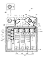
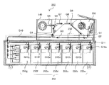
- FIG. 3 is a diagram inside the ATM 100 for explaining the entire transport route.
- 4 to 9 are diagrams for explaining a banknote transport route during a transaction by a user (customer) at the ATM 100.
- FIG. 3 is a diagram inside the ATM 100 for explaining the entire transport route.
- 4 to 9 are diagrams for explaining a banknote transport route during a transaction by a user (customer) at the ATM 100.
- FIG. 3 is a diagram inside the ATM 100 for explaining the entire transport route.
- 4 to 9 are diagrams for explaining a banknote transport route during a transaction by a user (customer) at the ATM 100.
- the right side is the side operated by the customer.
- An input / output unit 132 is provided on the right side of the upper part of the ATM 100, and a temporary storage unit 140 is provided on the left side.
- the temporary holding unit 140 is fixed to the ATM 100 with a screw, a lock lever, a latch, or the like so that it can be attached to and detached from the ATM 100.
- a discrimination unit 150 is provided at the center of the ATM 100.
- the temporary holding unit 140a in the upper left of FIG. 3 shows a removed state.
- a storage unit 152 is provided at the bottom of the ATM 100.
- four vertically long banknote cassettes (152a, 152b, 152c, 152d) are arranged in parallel from the right for each denomination.
- a banknote 400 is stacked on each banknote cassette of the storage unit 152.
- a reject part 154 is provided on the lower left side of the ATM 100. In the reject unit 154, four reject cassettes (154a, 154b, 154c, 154d) are arranged in order from the top.
- a safe unit 170 is provided in the lower part of the ATM 100.
- the storage unit 152 and the reject unit 154 are provided inside the safe unit 170.
- the safe unit 170 is locked by a door with a key (not shown), and protects the internal storage unit 152 and the reject unit 154. That is, only a person who has the key of the safe unit 170 can supply banknotes directly to the storage unit 152 or collect banknotes directly from the storage unit 152.
- the temporary storage unit 140 since the temporary storage unit 140 is installed outside the safe unit 170, the temporary storage unit 140 can be attached and detached without having the key of the safe unit 170.
- a conveyance path P1 that descends obliquely to the lower left and a conveyance path P2 that proceeds to the left are provided so that the bills inserted into the insertion / ejection unit 132 are conveyed inside.
- a conveyance path P3 that travels to the left while passing through the discrimination unit 150 is provided, and is divided into two at the front end of the conveyance path P3, and a conveyance path P4 that proceeds diagonally to the right and a conveyance path P10 that proceeds to the left as it is.
- the conveyance path P4 is divided into two at the front end of the conveyance path P4, and a conveyance path P5 that goes straight up and a conveyance path P14 that goes diagonally to the upper right are provided.
- the conveyance path P5 is divided into two at the front end, and a conveyance path P6 that proceeds to the left and right and a conveyance path P7 that proceeds to the right are provided.
- a conveyance path P6 that proceeds to the left and right and a conveyance path P7 that proceeds to the right are provided.
- the temporary holding section 140 is entered.
- a conveyance path P8 that proceeds to the right is provided so as to be continuous with the conveyance path P7.
- a conveyance path P9 that is divided into two at the front end of the conveyance path P8 and proceeds obliquely to the right and a conveyance path P15 that proceeds obliquely to the right is provided.
- the conveyance path P10 proceeding to the left is divided into two by entering the safe unit 170, and a conveyance path P11 proceeding to the right and a conveyance path P16 traveling right below are provided.
- the conveyance path P11 passes through the upper part of each banknote cassette of the storage unit 152 and is provided to the right side.
- a conveyance path P12d corresponding to the bill cassette 152d is provided so as to proceed downward from the middle of the conveyance path P11.
- a conveyance path P12c corresponding to the banknote cassette 152c, a conveyance path P12b corresponding to the banknote cassette 152b, and a conveyance path P12a corresponding to the banknote cassette 152a are provided in the middle of the conveyance path P11.
- a conveyance path P13 is provided at the front end of the conveyance path P11.
- the conveyance path P13 turns right and then turns to the left. It goes out of the safe part 170 by the conveyance path P13.
- the leading end of the transport path P13 is connected to the rear end of the transport path P2.
- the downward conveying path P16 is provided along the right side of the four reject cassettes of the reject unit 154.
- a conveyance path P17a corresponding to the reject cassette 154a is provided from the conveyance path P16.
- a transport path P12b corresponding to the reject cassette 154b, a transport path P17c corresponding to the reject cassette 154c, and a transport path P17d corresponding to the reject cassette 154d are provided from the transport path P16.
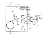
- FIG. 4 is a diagram schematically showing the transport structure in the vicinity of the temporary storage unit 140 and the connection between the temporary storage unit 140 and the ATM 100.
- a roller 162 for transporting banknotes and a sensor 163 for detecting passage of banknotes are appropriately arranged.
- the temporary storage unit 140 includes a sensor 141, a roller 142a, a winding film roller 142b, a banknote winding roller 143, and a film 144.
- the sensor 141 detects passage of banknotes.
- the film 144 is wound up with a banknote in between. Both ends of the film 144 are attached to the take-up film roller 142b.
- the banknote conveyed from the roller 162 is sandwiched between two films 144 and wound around the banknote winding roller 143.
- the temporary storage unit 140 includes a drive circuit 145 for driving the take-up film roller 142b and the like, and a storage unit memory 146 for storing the number of banknotes stored in the temporary storage unit 140.
- the number of banknotes stored in the temporary storage unit 140 is recorded in the storage unit memory 146 from the control unit 110a.
- the number of banknotes stored in the temporary storage unit 140 for example, when the ATM 100 is changed to the teller machine 200, the number data in the storage unit memory 146 is temporarily read by the teller machine 200 side.
- the number of banknotes stored in the holding unit 140 can be immediately grasped. Further, an ID number may be assigned to a plurality of temporary holding units 140 and the ID number of the corresponding temporary holding unit 140 may be stored in the holding unit memory 146.
- the sensor 141, the drive circuit 145, and the storage unit memory 146 of the temporary storage unit 140 are electrically connected to the control unit 110a of the ATM 100 main body through, for example, a connector (not shown). Attachment / detachment of the temporary holding unit 140 is detected by the control unit 110a, and the number of banknotes stored in the temporary holding unit 140 is managed by the control unit 110a. When the ID number is assigned to the temporary holding unit 140, the control unit 110a stores and manages the ID number and the mounting date / time of the mounted temporary holding unit 140.
- FIG. 5 is a diagram illustrating a route in which the inserted banknote is transported to the temporary storage unit 140 in the ATM 100.
- the banknotes inserted into the input / output unit 132 by the customer enter the discrimination unit 150 through the transport path P1, the transport path P2, and the transport path P3.
- the banknotes permitted by the discrimination result in the discrimination unit 150 are stored in the temporary storage unit 140 in the conveyance path P3 ⁇ the conveyance path P4 ⁇ the conveyance path P5 ⁇ the conveyance path P6.
- the deposit amount is displayed on the display panel 116 by the control unit 110a and waits for the customer's approval operation.
- FIG. 6 is a diagram illustrating a route in which banknotes are conveyed from the temporary storage unit 140 to the storage unit 152 in the ATM 100.
- the control unit 110 a conveys the banknote stored in the temporary storage unit 140 to the storage unit 152.
- the banknote is transported from the temporary holding unit 140 to the transport path P6 ⁇ the transport path P7 ⁇ the transport path P8 ⁇ the transport path P9 ⁇ the transport path P3 ⁇ the transport path P10 ⁇ the transport path P11, and the transport path according to the denomination (the transport path P12a).
- FIG. 7 is a diagram showing a route in which inserted banknotes are removed in the ATM 100.
- the inserted banknote is not a regular banknote (for example, foreign banknote)
- the banknotes inserted into the input / output unit 132 by the customer enter the discrimination unit 150 through the transport path P1, the transport path P2, and the transport path P3.
- the control unit 110a does not store the banknote in the temporary storage unit 140, but the transport path P3 ⁇ the transport path P4.
- the transport path P14 ⁇ the transport path P8 ⁇ the transport path P15 is returned to the loading / unloading unit 132.
- FIG. 8 is a diagram illustrating a route in which banknotes are conveyed from the temporary storage unit 140 to the reject unit 154 in the ATM 100.
- the banknotes identified by the discrimination unit 150 as being unsuitable for recycling (reuse) are stored in the reject unit 154.
- the bill enters the discrimination unit 150 from the temporary holding unit 140 in the conveyance path P6 ⁇ the conveyance path P7 ⁇ the conveyance path P8 ⁇ the conveyance path P9 ⁇ the conveyance path P3.
- the control unit 110a conveys the banknote from the transport path P10 to the transport path P16, and any one corresponding to the denomination
- the transfer path (transfer path P17a, transfer path P17b, transfer path P17c, or transfer path P17d) is stored in one of the four reject cassettes of the reject unit 154.
- FIG. 9 is a diagram illustrating a route through which banknotes are conveyed from the storage unit 152 to the insertion / extraction unit 132 in the ATM 100.
- a banknote is discharged by a customer's withdrawal operation.
- a banknote is taken out from the banknote cassette (152a, 152b, 152c or 152d) of the storage unit 152 through a transport path (transport path P12a, transport path P12b, transport path P12c or transport path P12d) according to the denomination.
- a banknote is conveyed to conveyance path P11-> conveyance path P13-> conveyance path P2-> conveyance path P3-> conveyance path P4.
- the process proceeds from the transport path P5 to the transport path P6.
- the banknotes transported to the temporary storage unit 140 are transported to the input / output unit 132 through the transport path P6 ⁇ the transport path P7 ⁇ the transport path P8 ⁇ the transport path P15.
- the banknotes are directly conveyed from the conveyance path P4 to the input / discharge unit 132, the bills are conveyed to the input / output unit 132 through the conveyance path P14 ⁇ the conveyance path P8 ⁇ the conveyance path P15.
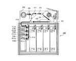
- FIG. 10 is a diagram illustrating a processing route for replenishing banknotes from the temporary storage unit 140 to the storage unit 152 in the ATM 100.
- the storage unit 152 does not need to unlock the door of the safe unit 170 when the storage unit 152 runs short of any denomination of banknotes. You can replenish banknotes.
- a clerk attaches an empty temporary storage unit 140 to the teller machine 200, for example, and moves a predetermined number of banknotes from the teller machine 200 to the empty temporary storage unit 140. After the predetermined number of banknotes 401 are stored, the temporary storage unit 140 of the teller machine 200 is removed from the teller machine 200. Then, the removed temporary holding unit 140 is attached to the ATM 100.
- the control unit 110a starts the replenishment process.
- the bills 401 stored in advance in the temporary storage unit 140 are transported by the control unit 110 a to the corresponding denomination bill cassette in the storage unit 152.
- the bill advances through the transport path P6 ⁇ the transport path P7 ⁇ the transport path P8 ⁇ the transport path P9 ⁇ the transport path P3 ⁇ the transport path P10 ⁇ the transport path P11 ⁇ the transport path P12b, and the bill is replenished to the bill cassette 152b.
- a predetermined number of banknotes 402 are replenished to the banknote cassette 152b of the storage unit 152.
- the predetermined number of sheets is, for example, 200 sheets depending on the size of the temporary storage unit 140.
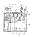
- FIG. 11 is a diagram illustrating a processing route for collecting the banknotes in the storage unit 152 to the temporary storage unit 140 in the ATM 100.
- the temporary storage unit 140 performs a process of collecting a part of the banknotes in the storage unit 152. Thereby, even if it does not unlock the door of the safe part 170, some banknotes of the storage part 152 can be collect
- the banknote 403 advances in the transport path P12b ⁇ the transport path P11 ⁇ the transport path P13 ⁇ the transport path P2 ⁇ the transport path P3 ⁇ the transport path P4 ⁇ the transport path P5 ⁇ the transport path P6 and is stored in the temporary storage unit 140.
- a predetermined number of banknotes 404 are collected in the temporary storage unit 140, and a space for the banknote 403 is created in the banknote cassette 152b of the storage unit 152.
- the predetermined number of sheets is, for example, 200 sheets depending on the size of the temporary storage unit 140.
- the bank may exchange the temporary holding unit 140 containing the collected banknote 404 and the empty temporary holding unit 140, or the temporary holding unit containing the collected banknote 404. 140 may be attached to the teller machine 200 and the bill 404 may be transferred to the teller machine 200.
- the collection process may be started by the control unit 210a of the teller machine 200 after receiving an instruction from the clerk.
- FIG. 12 is a diagram of the inside of the teller machine 200 and is a diagram for explaining a transport route.
- a loading / discharging unit 232 is provided on the right side of the upper portion of the teller machine 200, and a temporary storage unit 140 is provided on the opposite side.
- the temporary holding unit 140 is fixed to the teller machine 200 with a screw, a lock lever, a latch, or the like so that it can be attached to and detached from the teller machine 200 in the same manner as the ATM 100.
- Temporary holding unit 140a shows a removed state.
- a discrimination unit 250 is provided in the center of the teller machine 200.
- the storage unit 252 is provided in the lower stage of the teller machine 200.
- seven vertically long banknote cassettes (252a, 252b, 252c, 252d, 252e, 252f, and 252g) are arranged in parallel from the right for each denomination.
- the banknotes 400 are stacked in the vertical direction on each banknote cassette of the storage unit 252.
- a reject unit 254 is provided on the lower left side of the teller machine 200.
- the reject unit 254 also has four reject cassettes (254a, 254b, 254c, and 254d) arranged in order from the top.
- a safe unit 270 is provided at the lower part of the teller machine 200.
- the storage unit 252 and the reject unit 254 are disposed inside the safe unit 270.
- the safe unit 270 is locked by a door with a key (not shown) and protects the internal storage unit 252 and the reject unit 254. In other words, only a person who has the key of the safe unit 270 can supply banknotes directly to the storage unit 252 or collect banknotes directly from the storage unit 252.
- the temporary storage unit 140 is installed outside the safe unit 270, the temporary storage unit 140 can be attached and detached without having the key of the safe unit 270.
- a caster 272 is provided at the bottom of the teller machine 200.
- a conveyance path Q1 that descends obliquely to the lower left and a conveyance path Q2 that proceeds to the left are provided so that the bills inserted into the insertion / ejection unit 232 are conveyed inside.
- a conveyance path Q3 that travels to the left while passing through the discrimination section 250 is provided, and is divided into two at the front end of the conveyance path Q3, and a conveyance path Q4 that travels diagonally to the right and a conveyance path Q10 that travels to the left as it is.
- the conveyance path Q4 is divided into two at the front end of the conveyance path Q4, and a conveyance path Q5 that goes straight up and a conveyance path Q14 that goes diagonally to the upper right are provided.
- a conveyance path Q6 that is divided into two at the front end of the conveyance path Q5 and proceeds to the left and right and a conveyance path Q7 that proceeds to the right is provided. Proceeding to the left in the conveyance path Q6, the temporary holding section 140 is entered. A conveyance path Q8 that proceeds to the right is provided so as to be continuous with the conveyance path Q7. The conveyance path Q8 is divided into two at the tip of the conveyance path Q8, and a conveyance path Q9 that proceeds obliquely to the right and a conveyance path Q15 that proceeds obliquely to the right are provided.
- the conveyance path Q10 proceeding to the left is divided into two by entering the safe 270, and a conveyance path Q11 proceeding to the right and a conveyance path Q16 proceeding directly below are provided.
- the conveyance path Q11 passes through the upper part of each bill cassette in the storage unit 252 and is provided to the right side.
- a conveyance path Q12g corresponding to the banknote cassette 252g is provided so as to proceed downward from the middle of the conveyance path Q11.
- a conveyance path Q12b corresponding to the banknote cassette 252b and a conveyance path Q12a corresponding to the banknote cassette 252a are provided.
- a conveyance path Q13 is provided at the front end of the conveyance path Q11. Go out of safe 270 on transport path Q13. The leading end of the transport path Q13 is connected to the rear end of the transport path Q2.
- the downward conveying path Q16 is provided along the left side of the four reject cassettes of the reject unit 254.
- a transport path Q17a corresponding to the reject cassette 254a is provided so as to proceed to the right from the middle of the transport path Q16.
- a transport path Q17b corresponding to the reject cassette 254b, a transport path Q17c corresponding to the reject cassette 254c, and a transport path Q17d corresponding to the reject cassette 254d are provided in the middle of the transport path Q16.
- FIG. 13 is a diagram illustrating a route in which the inserted banknote is conveyed to the storage unit 252 via the temporary storage unit 140 in a normal transaction of the teller machine 200.
- the bill inserted by the customer into the input / discharge unit 232 enters the discrimination unit 250 through the transport path Q1 ⁇ the transport path Q2 ⁇ the transport path Q3.
- the banknotes permitted by the discrimination result in the discrimination unit 250 are stored in the temporary storage unit 140 in the conveyance path Q3 ⁇ the conveyance path Q4 ⁇ the conveyance path Q5 ⁇ the conveyance path Q6.
- the banknotes stored in the temporary storage unit 140 are transported from the temporary storage unit 140 to the transport path Q6 ⁇ the transport path Q7 ⁇ the transport path Q8 ⁇ the transport path Q9 ⁇ the transport path Q3 ⁇ the transport path Q10 ⁇ the transport path Q11 to be denominated.
- the corresponding transport path (transport path Q12a to transport path Q12g) is selected and stored in one of the banknote cassettes (252a to 252g) of the storage unit 252.
- FIG. 14 is a diagram illustrating a processing route for replenishing banknotes from the temporary storage unit 140 to the storage unit 252 in the teller machine 200.
- the storage unit 252 does not need to unlock the door of the safe unit 270 when any banknote of any denomination is insufficient in the storage unit 252. You can replenish banknotes. This process is equivalent to the replenishment process in the ATM 100 described with reference to FIG.
- banknotes are insufficient for the denomination of the banknote cassette 252a of the storage unit 252.
- a predetermined number of banknotes 405 stored in advance in the temporary storage unit 140 are conveyed to the banknote cassette 252a of the storage unit 252 by the control unit 210a.
- the banknote advances in the transport path Q6 ⁇ the transport path Q7 ⁇ the transport path Q8 ⁇ the transport path Q9 ⁇ the transport path Q3 ⁇ the transport path Q10 ⁇ the transport path Q11 ⁇ the transport path Q12a and enters the banknote cassette 252a of the storage unit 252. To be replenished.
- the control unit 210a performs a replenishment process in response to an instruction from a clerk.
- FIG. 15 is a diagram illustrating a processing route for collecting bills in the storage unit 252 to the temporary storage unit 140 in the teller machine 200.
- the temporary storage unit 140 performs a process of collecting a part of the banknote in the storage unit 252.
- a part of the banknote 400 of the storage unit 252 can be collected without unlocking the door of the safe unit 170. This process is equivalent to the collection process in the ATM 100 described with reference to FIG.
- a banknote 407 that is a part of the banknote 400 stored in the banknote cassette 252c of the storage section 252 is conveyed to the temporary storage section 140 by the control section 210a. Specifically, the banknote 407 advances through the transport path Q12c ⁇ the transport path Q11 ⁇ the transport path Q13 ⁇ the transport path Q2 ⁇ the transport path Q3 ⁇ the transport path Q4 ⁇ the transport path Q5 ⁇ the transport path Q6 and is stored in the temporary storage unit 140.
- a predetermined number of banknotes 408 are collected in the temporary storage unit 140, and a space for the banknote 407 is created in the banknote cassette 252c of the storage unit 252.
- the predetermined number is 200, for example, although it varies depending on the size of the temporary holding unit 140.
- the emptying method is the same as that described with reference to FIG.
- the collection process may be started by the control unit 210a after receiving an instruction from a bank clerk.
- the transaction processing of banknotes in the ATM 100 and the teller machine 200 is substantially the same. Therefore, the description is given only for the ATM 100 in order to avoid duplication, but the same applies to the teller machine 200.
- the following processing is mainly performed by the control unit 110a in the ATM 100, and is mainly performed by the control unit 210a in the teller machine 200.
- FIG. 16 is a flowchart for explaining a procedure of a process of suspending the cash transaction apparatus until a management company comes and replenishes banknotes when banknotes are insufficient in the ATM 100. Conventional operation.
- step S10 It is determined whether the withdrawal amount has been input.
- the withdrawal amount is input by the customer at the ATM 100 and by the clerk at the teller machine 200. Step S10 is repeated until the withdrawal amount is input (NO in step S10). If it is determined that the withdrawal amount has been input (YES in step S10), it is checked whether there is a withdrawal amount banknote (step S12). Based on the banknote number data stored in the memory 112, it is checked whether or not the corresponding banknote is in the storage unit 152.
- step S14 it is determined whether it can be pulled out. If it is determined that the corresponding banknote is in the storage unit 152 and can be withdrawn (YES in step S14), the withdrawal process is continued (step S16).
- step S14 If the corresponding banknote is not in the storage unit 152, it is determined that the banknote cannot be pulled out (NO in step S14), information on the insufficient banknote is stored in the memory 112 (step S18), and information indicating that the banknote is insufficient is stored in the management company 320. (Step S20). And the process which pauses ATM100 is performed (step S22). As the suspension process, for example, a message such as “Currently not available” is displayed on the display panel 116, and the ATM 100 is shifted to a mode in which an operation from the customer is not accepted. Thereafter, a person in charge is dispatched from the management company that has received the notification to the store, and after the banknotes are replenished in the storage unit 152, the transaction at the ATM 100 can be resumed.
- FIG. 17 is a flowchart for explaining processing in a case where the cash transaction apparatus is suspended until the management company comes and collects the banknote when the banknote is full in the ATM 100. Conventional operation.
- step S30 It is determined whether the bill has been deposited by the customer (step S30).
- the deposit of the banknote is determined based on the output of the sensor provided in the insertion / ejection unit 132. Step S30 is repeated until it is determined that the banknote has been deposited (step S30 NO). If it is determined that the banknote has been deposited (step S30 YES), the type and number of banknotes deposited are checked (step S32). The deposited banknotes are checked by the discrimination unit 150 for the type and number of banknotes.
- step S34 It is determined whether the deposited banknote can be stored in the storage unit 152 (step S34). Whether it can be stored is determined based on the bill number data stored in each current bill cassette stored in the memory 112 and a full / near full detection sensor provided in the corresponding bill cassette.
- step S34 If it is determined that the deposited banknote can be stored in the storage unit 152 (YES in step S34), the depositing process is continued (step S36), and the deposited banknote is stored in the corresponding banknote cassette in the storage unit 152.
- step S34 If it is determined that the deposited banknote cannot be stored in the storage unit 152 (NO in step S34), that is, if it is determined that the corresponding banknote cassette in the storage unit 152 is full (full), the full / near full information is stored in the memory 112. (Step S38) and the management company 320 is notified of full / near full information (step S40). Then, the ATM 100 is suspended (step S42). The pause process is the same as step S22 in FIG. Then, after the person in charge is dispatched from the management company that has received the notification to the store and the banknotes are collected from the storage unit 152, the transaction at the ATM 100 can be resumed.
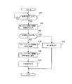
- FIG. 18 is a flowchart illustrating a procedure of processing for replenishing banknotes from the temporary storage unit 140 to the storage unit 152 when banknotes are insufficient in the ATM 100. 10 and 14, banknotes can be replenished into the storage unit 152 without unlocking the door of the safe unit 170.
- step S50 Prepare another temporary storage section filled with banknotes (step S50).
- the clerk prepares another temporary storage unit filled with banknotes.
- the filling method is as described in FIG.
- step S52 the clerk replaces the temporary storage unit 140 filled with banknotes (step S52). It is determined whether the temporary holding unit 140 is attached to the ATM 100 (step S54). It is determined whether the temporary holding unit 140 is attached to the ATM 100 based on whether the CPU 110 can normally communicate with the temporary holding unit 140. If the temporary holding unit 140 determines that it is not normally attached to the ATM 100 (NO in Step S54), Step S54 is repeated until a warning or the like is displayed and the ATM 100 is normally attached.
- step S56 it is determined whether or not there are a predetermined number of banknotes in the temporary storage unit 140 (step S56). Whether there are more than a predetermined number of banknotes is determined from the banknote number data stored in the holding unit memory 146. If it is determined that there are not more than a predetermined number of banknotes in the temporary holding unit 140 (NO in step S56), the replenishment process is stopped and the process ends.
- step S58 If it is determined that there are more than a predetermined number of banknotes in the temporary holding unit 140 (YES in step S56), the replenishment process is started (step S58).
- a banknote is conveyed from the temporary storage part 140 to the discrimination part 150 (step S60).
- the discrimination part 150 Based on the discrimination result of the discrimination unit 150, it is determined whether the conveyed banknote is recyclable (step S62). If it is determined that the conveyed banknote is not recyclable (NO in step S62), the banknote identified as not recyclable is stored in the reject unit 154 (step S64).
- Step S62 If it is determined that the banknote can be recycled (YES in step S62), the banknote is stored in the corresponding banknote cassette of the storage unit 152 (step S66). Subsequent to Step S64 and Step S66, it is determined whether or not there is a bill remaining in the temporary storage unit 140 (Step S68). If it is determined that there is a remaining bill in the temporary holding unit 140 (YES in step S68), the process returns to step S58, and the next banknote is repeatedly conveyed from the temporary holding unit 140. If it is determined that there is no banknote remaining in the temporary storage unit 140 (NO in step S68), it is determined that the conveyance of the banknotes filled in the temporary storage unit 140 to the storage unit 152 is completed, and this process ends.
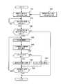
- FIG. 19 is a flowchart for explaining a processing procedure for collecting banknotes from the storage unit 152 to the temporary storage unit 140 when the banknotes are full or near full in the ATM 100. 11 and 15, the banknotes can be collected from the storage unit 152 without unlocking the door of the safe unit 170.
- Whether the banknote is full or near full is determined in the storage unit 152 (step S80). Whether the bill cassette corresponding to one of the denominations in the storage unit 152 is full or near full is determined by the output of the full detection sensor or the near full detection sensor.
- step S82 If the storage unit 152 determines that the banknote is not full or near-full (NO in step S80), it is determined whether an instruction to collect the banknote is received from the storage unit 152 (step S82). In this example, the recovery process is started when full or near full is detected with any denomination, and even if there is no detection of full or near full, the recovery process is performed if there is an instruction from a bank clerk.
- step S82 If it is determined that there is no instruction for collecting banknotes from the storage unit 152 (NO in step S82), the process returns to step S80.
- step S82 When it is determined that an instruction to collect banknotes is received from the storage unit 152 (YES in step S82), or when it is determined that the banknotes are full or near full (YES in step S80), the process proceeds to step S84.
- step S84 It is determined whether or not the number of banknotes in the temporary storage unit 140 is equal to or less than a predetermined number.
- the banknote in the temporary storage unit 140 is normally zero. This is because if a large number of banknotes remain in the temporary storage unit 140, the collection from the storage unit 152 will be hindered. If it is determined that the number of banknotes in the temporary holding unit 140 is not less than the predetermined number (step S84 NO), the collection process is stopped and the process ends.
- step S86 a process of collecting banknotes from the storage unit 152 is started (step S86).
- the banknote cassette from which the banknotes are collected is a banknote cassette that has been fully or near-full detected, or a banknote cassette that has been instructed to be collected in step S82.
- the bill is conveyed from the storage unit 152 to the discrimination unit 150 (step S88). Based on the discrimination result of the discrimination unit 150, it is determined whether the conveyed banknote is recyclable (step S90). If it is determined that the conveyed banknote is not recyclable (step S90 NO), the banknote identified as not recyclable is stored in the reject unit 154 (step S94).
- step S92 If it is determined that the banknote can be recycled (step S90 YES), the banknote is stored in the temporary storage unit 140 (step S92). Subsequent to step S92 and step S94, it is determined whether the number of sheets stored in the temporary storage unit 140 is full (step S96). If it is determined that the number of sheets stored in the temporary storage unit 140 is not full (NO in step S96), the process returns to step S86, and the next banknote is repeatedly conveyed from the storage unit 152 to the temporary storage unit 140.
- step S96 When it is determined that the number of stored sheets in the temporary holding unit 140 is full or the number of collected banknotes is equal to or greater than the predetermined number (YES in step S96), the collection from the storage unit 152 is terminated. In addition, the type and number of banknotes stored are recorded in the holding unit memory 146.
- step S98 it is determined whether or not it has been replaced with an empty temporary holding unit 140 (step S98). This is because the ATM 100 cannot be used for normal transactions with the temporary holding unit 140 in a state where the collected banknotes are stored. Step S98 is repeated until the empty temporary holding unit 140 is replaced (NO in Step S98). If it is determined that it has been replaced with an empty temporary holding unit 140 (YES in step S98), the collection process is terminated because the collection is completed.
- the temporary holding unit 140 has a structure that can be attached to and detached from the cash transaction apparatus, the temporary holding unit 140 can be used by replacing the temporary holding unit 140 prepared in advance. Thereby, the down time of a cash transaction apparatus can be shortened more. Furthermore, since the temporary storage part of ATM100 and the teller machine 200 has compatibility, it becomes possible to perform replenishment and collection
- the controller 110a may determine the presence / absence of banknotes using the sensor 141. -Moreover, the lid
Landscapes
- Physics & Mathematics (AREA)
- General Physics & Mathematics (AREA)
- Engineering & Computer Science (AREA)
- Mechanical Engineering (AREA)
- Financial Or Insurance-Related Operations Such As Payment And Settlement (AREA)
- Pile Receivers (AREA)
Abstract
Description
図3は、ATM100内部の図で、搬送ルートの全体を説明するための図である。図4から図9は、ATM100で利用者(顧客)による取引中での、紙幣の搬送ルートを説明するための図である。
図12は、テラー機200内部の図で、搬送ルートを説明するための図である。図12で向かって右側が行員の操作側になる。テラー機200の上部の右側面に投入排出部232が設けられ、反対側に一時保留部140が設けられる。一時保留部140は、ATM100と同様にテラー機200にも着脱できるように、テラー機200にネジ、ロックレバーあるいはラッチ等で固定される。一時保留部140aは、外された状態を示す。テラー機200の中央に鑑別部250が設けられる。
次に、図16~図19を用いて、現金取引装置(ATM100及びテラー機200)の紙幣の回収及び補充処理の手順につき、従来の運用と本実施形態による処理を対比して説明する。
・紙葉類(紙幣)が不足した場合には一時保留部から紙葉類(紙幣)を補充し、紙葉類(紙幣)が一杯になった場合には一時保留部140に紙葉類(紙幣)を回収することで、行員が金庫の開閉を行うことができない店舗においても、管理会社の担当者の到着を待たずに、暫定的に紙葉類(現金)取引装置をほぼ継続的に運用することができる。また、一時保留部を利用して補充や回収処理を行うので、紙葉類(現金)取引装置のダウンタイムも短時間で済む。
・紙幣の補充や回収用に一時保留部を利用することで、専用の補充回収装置を設ける必要がなく、現金取引装置のサイズの大型化やコストアップを防止することができる。
・一時保留部140を現金取引装置から着脱できる構造にしたことで、予め用意した一時保留部140と入替えて運用することができる。これにより、現金取引装置のダウンタイムをより短時間化できる。さらに、ATM100とテラー機200の一時保留部が互換性を有することで、ATM100とテラー機200間で紙幣の補充や回収が容易にできるようになる。
・ATM100とテラー機200の両方で着脱可能な一時保留部を備えていることを説明したが、いずれか一方だけでもよい。ATM100とテラー機200のいずれか一方だけで着脱可能な一時保留部を備えていても、補充処理や回収処理は可能である。
・また、補充処理と回収処理は、いずれか一方だけ備えるようにしてもよい。
・上述した説明では、ATM100とテラー機200で一時保留部は、同一であると説明したが、接続部での互換性があればよく、ATM100用の一時保留部とテラー機200の一時保留部の外観や機能が、異なっていてもよい。
・一時保留部に保留部メモリを設けなくてもよい。制御部110aが、センサ141により紙幣有無を判断してもよい。
・また、一時保留部140に開閉可能な蓋を設け、内部に格納された紙幣を取出したり、逆に内部に紙幣を格納できるようにしてもよい。紙幣の回収・補充処理を行う際により便利になる。
110,210 CPU
110a,201a 制御部
112,211 メモリ
114,214 通信I/F
116,216 表示パネル
118,218 カードユニット
120,220 通帳ユニット
122,222 硬貨ユニット
130,230 紙幣ユニット
132,232 投入排出部
140 一時保留部
141 センサ
143 紙幣巻取ローラ
144 フィルム
145 駆動回路
146 保留部メモリ
150,250 鑑別部
152,252 収納部
154,254 リジェクト部
160,260 搬送部
162 ローラ
163 センサ
170,270 金庫部
200 テラー機
300 ネットワーク
310 ホストコンピュータ
320 管理会社
400 紙幣
Claims (8)
- 利用者による紙葉類の取引に使用される紙葉類取引装置において、
紙葉類が投入される投入部と、
前記投入部に投入された紙葉類を収納する収納部と、
所定枚数の紙葉類を一時的に格納する一時保留部と、
処理内容に応じて前記投入部と前記収納部間で前記紙葉類の搬送を制御する制御部と、を備え
前記一時保留部は、前記紙葉類取引装置に着脱可能に設けられ、
前記制御部は、前記利用者による紙葉類取引の処理においては、前記一時保留部を前記投入部に投入された紙葉類が前記収納部に収納される前に一時的に保留する場所となるよう制御し、前記収納部から前記紙葉類を回収する処理においては、前記一時保留部を前記収納部の紙葉類の少なくとも一部を回収させる場所となるよう制御し、前記収納部へ前記紙葉類を補充する処理においては、前記一時保留部に予め格納されている紙葉類を前記収納部に搬送するよう制御する処理を行う
ことを特徴とする紙葉類取引装置。 - 前記収納部を内部に収納し施錠可能な金庫を備え、
前記一時保留部は、前記金庫の外部に設置される
ことを特徴とする請求項1に記載の紙葉類取引装置。 - 前記収納部は、複数のカセットに区分けされ、
前記複数のカセットには、それぞれ前記紙葉類のフルまたはニアフルを検知する検知部が設けられ、
前記制御部は、前記検知部による検知に応じて、前記紙葉類を回収する処理を行う
ことを特徴とする請求項1に記載の紙葉類取引装置。 - 前記紙葉類取引装置は、前記紙葉類を回収する処理において、前記収納部から所定枚数分の紙葉類を回収する
ことを特徴とする請求項1に記載の紙葉類取引装置。 - 前記紙葉類取引装置は、主に顧客との取引に用いられるATMまたは主に行員が取り扱うテラー機での少なくともいずれかである
ことを特徴とする請求項1に記載の紙葉類取引装置。 - 前記一時保留部は、前記紙葉類取引装置に着脱可能に設けられ、
前記紙葉類取引装置は、主に顧客との取引に用いられるATM及び主に行員が取り扱うテラー機の両方に適用され、前記ATM及び前記テラー機にそれぞれ着脱可能に設けられる前記一時保留部は、互換性がある
ことを特徴とする請求項1に記載の紙葉類取引装置。 - 請求項6に記載の紙葉類取引装置の運用方法であって、
前記ATM及び前記テラー機の紙葉類取引装置でいずれか一方の収納部で紙葉類がフルまたはニアフルになった場合に、前記フルまたはニアフルの前記紙葉類取引装置をフルの紙葉類取引装置とし、前記フルの紙葉類取引装置で前記紙葉類の回収処理を行い、前記回収された紙葉類が格納された一時保留部を外し、フルではない前記紙葉類取引装置に装着して、前記一時保留部に格納された紙葉類を前記フルではない紙葉類取引装置の収納部に移動させる処理を行い、
前記ATM及び前記テラー機の紙葉類取引装置でいずれか一方の収納部で紙葉類が不足した場合に、紙葉類不足ではない前記紙葉類取引装置で前記紙葉類の回収処理を行い、前記回収された紙葉類が格納された一時保留部を外し、紙葉類不足の前記紙葉類取引装置に装着して、前記一時保留部で格納された紙葉類を前記紙葉類不足の紙葉類取引装置の収納部に補充する処理を行う
ことを特徴とする紙葉類取引装置の運用方法。 - 利用者による紙葉類の取引に使用される紙葉類取引装置に設けられ、前記利用者から前記紙葉類取引装置に入金された紙葉類を収納部に収納する前に一時的に保留する一時保留装置において、
前記紙葉類取引装置には前記収納部を内部に保護する金庫が設けられ、前記一時保留装置は前記金庫外に設置され、かつ前記紙葉類取引装置に対して着脱可能に設けられ、
前記一時保留装置は、前記収納部で紙葉類がフルまたはニアフルになった場合に、前記収納部から搬送され回収される前記紙葉類を格納し、前記収納部で紙葉類が不足する場合には、前記収納部へ補充する紙葉類を格納する
ことを特徴とする一時保留装置。
Priority Applications (5)
| Application Number | Priority Date | Filing Date | Title |
|---|---|---|---|
| CN201380078940.6A CN105474278A (zh) | 2013-08-28 | 2013-08-28 | 纸页类交易装置 |
| EP13892716.5A EP3040951A4 (en) | 2013-08-28 | 2013-08-28 | BANKNOTE TRANSACTION DEVICE |
| PCT/JP2013/073068 WO2015029174A1 (ja) | 2013-08-28 | 2013-08-28 | 紙葉類取引装置 |
| JP2015533856A JPWO2015029174A1 (ja) | 2013-08-28 | 2013-08-28 | 紙葉類取引装置 |
| US15/046,719 US20160163145A1 (en) | 2013-08-28 | 2016-02-18 | Paper sheet transaction device |
Applications Claiming Priority (1)
| Application Number | Priority Date | Filing Date | Title |
|---|---|---|---|
| PCT/JP2013/073068 WO2015029174A1 (ja) | 2013-08-28 | 2013-08-28 | 紙葉類取引装置 |
Related Child Applications (1)
| Application Number | Title | Priority Date | Filing Date |
|---|---|---|---|
| US15/046,719 Continuation US20160163145A1 (en) | 2013-08-28 | 2016-02-18 | Paper sheet transaction device |
Publications (1)
| Publication Number | Publication Date |
|---|---|
| WO2015029174A1 true WO2015029174A1 (ja) | 2015-03-05 |
Family
ID=52585792
Family Applications (1)
| Application Number | Title | Priority Date | Filing Date |
|---|---|---|---|
| PCT/JP2013/073068 Ceased WO2015029174A1 (ja) | 2013-08-28 | 2013-08-28 | 紙葉類取引装置 |
Country Status (5)
| Country | Link |
|---|---|
| US (1) | US20160163145A1 (ja) |
| EP (1) | EP3040951A4 (ja) |
| JP (1) | JPWO2015029174A1 (ja) |
| CN (1) | CN105474278A (ja) |
| WO (1) | WO2015029174A1 (ja) |
Cited By (1)
| Publication number | Priority date | Publication date | Assignee | Title |
|---|---|---|---|---|
| JP2021068235A (ja) * | 2019-10-24 | 2021-04-30 | 富士通フロンテック株式会社 | 取引システム、取引装置、及び取引方法 |
Families Citing this family (9)
| Publication number | Priority date | Publication date | Assignee | Title |
|---|---|---|---|---|
| EP3480795B1 (en) * | 2016-07-29 | 2023-10-11 | Glory Ltd. | Money processing apparatus |
| WO2019150516A1 (ja) * | 2018-01-31 | 2019-08-08 | 富士通フロンテック株式会社 | 紙葉類取扱装置および紙葉類取扱装置におけるpldのコンフィギュレーション方法 |
| US11145152B2 (en) * | 2018-03-09 | 2021-10-12 | Global Payments Gaming Services Inc. | Bill-loading machine |
| WO2019180958A1 (ja) * | 2018-03-23 | 2019-09-26 | 富士通フロンテック株式会社 | 紙葉類取扱装置 |
| ES2985975T3 (es) | 2018-07-19 | 2024-11-08 | Crane Payment Innovations Inc | Nivel de bolsa de efectivo multipropósito y presencia de billetes en el detector de depósito |
| JP7368183B2 (ja) * | 2019-10-30 | 2023-10-24 | グローリー株式会社 | 貨幣入出金装置、貨幣処理システム及び貨幣処理方法 |
| US11804093B2 (en) | 2022-02-18 | 2023-10-31 | Hyosung TNS Inc. | Medium storage device and method of controlling the medium storage device |
| US11987463B2 (en) | 2022-02-22 | 2024-05-21 | Hyosung TNS Inc. | Medium storage device and method of controlling the medium storage device |
| KR20230135718A (ko) * | 2022-03-16 | 2023-09-26 | 효성티앤에스 주식회사 | 금융 자동화 기기 및 이를 제어하는 방법 |
Citations (3)
| Publication number | Priority date | Publication date | Assignee | Title |
|---|---|---|---|---|
| JP2004295909A (ja) * | 1994-05-20 | 2004-10-21 | Fujitsu Ltd | 紙葉取扱装置 |
| JP2005196607A (ja) | 2004-01-09 | 2005-07-21 | Oki Electric Ind Co Ltd | 自動取引装置 |
| JP2008171451A (ja) * | 2008-03-26 | 2008-07-24 | Hitachi Omron Terminal Solutions Corp | 紙幣入出金機 |
Family Cites Families (15)
| Publication number | Priority date | Publication date | Assignee | Title |
|---|---|---|---|---|
| JPS5680792A (en) * | 1979-12-05 | 1981-07-02 | Omron Tateisi Electronics Co | Circulationntype money receiving and paying device |
| JP2728337B2 (ja) * | 1992-04-17 | 1998-03-18 | ローレルバンクマシン株式会社 | 貨幣補充回収システム |
| JPH1027274A (ja) * | 1996-07-09 | 1998-01-27 | Oki Electric Ind Co Ltd | 紙幣自動入出金装置 |
| JP2001357456A (ja) * | 2000-06-09 | 2001-12-26 | Sogo Keibi Hosho Co Ltd | 有価媒体自動預け払いシステム、有価媒体自動預け払い機、カセットおよび有価媒体の補充管理方法 |
| JP4292012B2 (ja) * | 2003-02-10 | 2009-07-08 | 日立オムロンターミナルソリューションズ株式会社 | 紙幣入出金装置 |
| JP2004318415A (ja) * | 2003-04-15 | 2004-11-11 | Oki Electric Ind Co Ltd | 現金取扱システム |
| JP5119335B2 (ja) * | 2008-09-22 | 2013-01-16 | 富士通フロンテック株式会社 | 紙幣入金処理ユニット、および紙幣入金処理ユニットに脱着可能な投入・返却ユニット |
| JP4895231B2 (ja) * | 2009-01-07 | 2012-03-14 | Necフィールディング株式会社 | 紙類繰り出し装置の寿命管理システム、寿命管理方法、寿命管理端末、及び紙類繰り出し装置 |
| JP5267345B2 (ja) * | 2009-06-17 | 2013-08-21 | 沖電気工業株式会社 | 媒体処理装置 |
| JP5500267B2 (ja) * | 2010-12-01 | 2014-05-21 | 沖電気工業株式会社 | 自動取引装置 |
| JP5633451B2 (ja) * | 2011-03-29 | 2014-12-03 | 沖電気工業株式会社 | 紙幣取扱装置、及び、当該紙幣取扱装置に用いる受渡ユニット |
| JP5815301B2 (ja) * | 2011-06-24 | 2015-11-17 | グローリー株式会社 | 現金処理システム、現金処理方法、管理部および現金出納装置 |
| JP5783005B2 (ja) * | 2011-11-18 | 2015-09-24 | 沖電気工業株式会社 | 媒体処理装置 |
| JP5821588B2 (ja) * | 2011-12-06 | 2015-11-24 | 沖電気工業株式会社 | 紙幣処理装置 |
| JP5974624B2 (ja) * | 2012-05-17 | 2016-08-23 | 沖電気工業株式会社 | 紙葉類搬送装置及び紙葉類取扱装置 |
-
2013
- 2013-08-28 JP JP2015533856A patent/JPWO2015029174A1/ja active Pending
- 2013-08-28 WO PCT/JP2013/073068 patent/WO2015029174A1/ja not_active Ceased
- 2013-08-28 CN CN201380078940.6A patent/CN105474278A/zh active Pending
- 2013-08-28 EP EP13892716.5A patent/EP3040951A4/en not_active Withdrawn
-
2016
- 2016-02-18 US US15/046,719 patent/US20160163145A1/en not_active Abandoned
Patent Citations (3)
| Publication number | Priority date | Publication date | Assignee | Title |
|---|---|---|---|---|
| JP2004295909A (ja) * | 1994-05-20 | 2004-10-21 | Fujitsu Ltd | 紙葉取扱装置 |
| JP2005196607A (ja) | 2004-01-09 | 2005-07-21 | Oki Electric Ind Co Ltd | 自動取引装置 |
| JP2008171451A (ja) * | 2008-03-26 | 2008-07-24 | Hitachi Omron Terminal Solutions Corp | 紙幣入出金機 |
Non-Patent Citations (1)
| Title |
|---|
| See also references of EP3040951A4 |
Cited By (2)
| Publication number | Priority date | Publication date | Assignee | Title |
|---|---|---|---|---|
| JP2021068235A (ja) * | 2019-10-24 | 2021-04-30 | 富士通フロンテック株式会社 | 取引システム、取引装置、及び取引方法 |
| JP7320899B2 (ja) | 2019-10-24 | 2023-08-04 | 富士通フロンテック株式会社 | 取引システム、取引装置、及び取引方法 |
Also Published As
| Publication number | Publication date |
|---|---|
| JPWO2015029174A1 (ja) | 2017-03-02 |
| EP3040951A4 (en) | 2016-09-14 |
| EP3040951A1 (en) | 2016-07-06 |
| US20160163145A1 (en) | 2016-06-09 |
| CN105474278A (zh) | 2016-04-06 |
Similar Documents
| Publication | Publication Date | Title |
|---|---|---|
| JP5156439B2 (ja) | 紙幣取扱装置及び現金自動取引装置 | |
| JPWO2015029174A1 (ja) | 紙葉類取引装置 | |
| CN103946901B (zh) | 纸币处理装置 | |
| CN104246836B (zh) | 货币处理装置 | |
| JP2010108197A (ja) | 自動取引装置 | |
| CN102483870A (zh) | 货币处理装置 | |
| JPH0922476A (ja) | 自動取引装置および自動取引装置におけるリジェクト貨幣の取扱い方法 | |
| JP2010272024A (ja) | 自動取引装置 | |
| WO2015049733A1 (ja) | 紙幣取扱装置 | |
| JP2726308B2 (ja) | 紙弊入出金装置 | |
| JP2001331843A (ja) | 紙幣入出金装置 | |
| JP3190884B2 (ja) | 自動取引システム | |
| JP2007034522A (ja) | 自動釣銭機および自動補充回収機 | |
| CN106981142B (zh) | 自助设备、自动交易系统及货币收纳方法 | |
| JP2002367011A (ja) | 紙幣取扱装置 | |
| JP2503081B2 (ja) | 現金入出金装置 | |
| JP2761567B2 (ja) | 紙幣入出金装置 | |
| JP6932061B2 (ja) | 有価媒体処理装置、有価媒体処理システム、プログラムおよび有価媒体処理方法 | |
| JPH056479A (ja) | 現金自動取引装置 | |
| JP4330701B2 (ja) | 紙幣入出金自動取引機 | |
| JPH07129819A (ja) | 紙幣入出金装置 | |
| JP2902764B2 (ja) | 現金入出金装置 | |
| JPH06259642A (ja) | 自動取引装置 | |
| JPH0544073B2 (ja) | ||
| JP2002329230A (ja) | 自動取引装置 |
Legal Events
| Date | Code | Title | Description |
|---|---|---|---|
| WWE | Wipo information: entry into national phase |
Ref document number: 201380078940.6 Country of ref document: CN |
|
| 121 | Ep: the epo has been informed by wipo that ep was designated in this application |
Ref document number: 13892716 Country of ref document: EP Kind code of ref document: A1 |
|
| ENP | Entry into the national phase |
Ref document number: 2015533856 Country of ref document: JP Kind code of ref document: A |
|
| REEP | Request for entry into the european phase |
Ref document number: 2013892716 Country of ref document: EP |
|
| WWE | Wipo information: entry into national phase |
Ref document number: 2013892716 Country of ref document: EP |
|
| NENP | Non-entry into the national phase |
Ref country code: DE |