WO2015029267A1 - 配線モジュール - Google Patents
配線モジュール Download PDFInfo
- Publication number
- WO2015029267A1 WO2015029267A1 PCT/JP2013/081116 JP2013081116W WO2015029267A1 WO 2015029267 A1 WO2015029267 A1 WO 2015029267A1 JP 2013081116 W JP2013081116 W JP 2013081116W WO 2015029267 A1 WO2015029267 A1 WO 2015029267A1
- Authority
- WO
- WIPO (PCT)
- Prior art keywords
- detection terminal
- terminal
- connection
- connection member
- positioning
- Prior art date
- Legal status (The legal status is an assumption and is not a legal conclusion. Google has not performed a legal analysis and makes no representation as to the accuracy of the status listed.)
- Ceased
Links
Images


Classifications
-
- H—ELECTRICITY
- H01—ELECTRIC ELEMENTS
- H01R—ELECTRICALLY-CONDUCTIVE CONNECTIONS; STRUCTURAL ASSOCIATIONS OF A PLURALITY OF MUTUALLY-INSULATED ELECTRICAL CONNECTING ELEMENTS; COUPLING DEVICES; CURRENT COLLECTORS
- H01R11/00—Individual connecting elements providing two or more spaced connecting locations for conductive members which are, or may be, thereby interconnected, e.g. end pieces for wires or cables supported by the wire or cable and having means for facilitating electrical connection to some other wire, terminal, or conductive member, blocks of binding posts
- H01R11/11—End pieces or tapping pieces for wires, supported by the wire and for facilitating electrical connection to some other wire, terminal or conductive member
-
- H—ELECTRICITY
- H01—ELECTRIC ELEMENTS
- H01G—CAPACITORS; CAPACITORS, RECTIFIERS, DETECTORS, SWITCHING DEVICES, LIGHT-SENSITIVE OR TEMPERATURE-SENSITIVE DEVICES OF THE ELECTROLYTIC TYPE
- H01G2/00—Details of capacitors not covered by a single one of groups H01G4/00-H01G11/00
- H01G2/02—Mountings
- H01G2/04—Mountings specially adapted for mounting on a chassis
-
- H—ELECTRICITY
- H01—ELECTRIC ELEMENTS
- H01G—CAPACITORS; CAPACITORS, RECTIFIERS, DETECTORS, SWITCHING DEVICES, LIGHT-SENSITIVE OR TEMPERATURE-SENSITIVE DEVICES OF THE ELECTROLYTIC TYPE
- H01G4/00—Fixed capacitors; Processes of their manufacture
- H01G4/38—Multiple capacitors, i.e. structural combinations of fixed capacitors
-
- H—ELECTRICITY
- H01—ELECTRIC ELEMENTS
- H01M—PROCESSES OR MEANS, e.g. BATTERIES, FOR THE DIRECT CONVERSION OF CHEMICAL ENERGY INTO ELECTRICAL ENERGY
- H01M10/00—Secondary cells; Manufacture thereof
- H01M10/42—Methods or arrangements for servicing or maintenance of secondary cells or secondary half-cells
- H01M10/48—Accumulators combined with arrangements for measuring, testing or indicating the condition of cells, e.g. the level or density of the electrolyte
- H01M10/482—Accumulators combined with arrangements for measuring, testing or indicating the condition of cells, e.g. the level or density of the electrolyte for several batteries or cells simultaneously or sequentially
-
- H—ELECTRICITY
- H01—ELECTRIC ELEMENTS
- H01M—PROCESSES OR MEANS, e.g. BATTERIES, FOR THE DIRECT CONVERSION OF CHEMICAL ENERGY INTO ELECTRICAL ENERGY
- H01M2220/00—Batteries for particular applications
- H01M2220/20—Batteries in motive systems, e.g. vehicle, ship, plane
-
- H—ELECTRICITY
- H01—ELECTRIC ELEMENTS
- H01M—PROCESSES OR MEANS, e.g. BATTERIES, FOR THE DIRECT CONVERSION OF CHEMICAL ENERGY INTO ELECTRICAL ENERGY
- H01M50/00—Constructional details or processes of manufacture of the non-active parts of electrochemical cells other than fuel cells, e.g. hybrid cells
- H01M50/50—Current conducting connections for cells or batteries
- H01M50/502—Interconnectors for connecting terminals of adjacent batteries; Interconnectors for connecting cells outside a battery casing
- H01M50/514—Methods for interconnecting adjacent batteries or cells
- H01M50/517—Methods for interconnecting adjacent batteries or cells by fixing means, e.g. screws, rivets or bolts
-
- H—ELECTRICITY
- H01—ELECTRIC ELEMENTS
- H01M—PROCESSES OR MEANS, e.g. BATTERIES, FOR THE DIRECT CONVERSION OF CHEMICAL ENERGY INTO ELECTRICAL ENERGY
- H01M50/00—Constructional details or processes of manufacture of the non-active parts of electrochemical cells other than fuel cells, e.g. hybrid cells
- H01M50/50—Current conducting connections for cells or batteries
- H01M50/502—Interconnectors for connecting terminals of adjacent batteries; Interconnectors for connecting cells outside a battery casing
- H01M50/521—Interconnectors for connecting terminals of adjacent batteries; Interconnectors for connecting cells outside a battery casing characterised by the material
- H01M50/522—Inorganic material
-
- Y—GENERAL TAGGING OF NEW TECHNOLOGICAL DEVELOPMENTS; GENERAL TAGGING OF CROSS-SECTIONAL TECHNOLOGIES SPANNING OVER SEVERAL SECTIONS OF THE IPC; TECHNICAL SUBJECTS COVERED BY FORMER USPC CROSS-REFERENCE ART COLLECTIONS [XRACs] AND DIGESTS
- Y02—TECHNOLOGIES OR APPLICATIONS FOR MITIGATION OR ADAPTATION AGAINST CLIMATE CHANGE
- Y02E—REDUCTION OF GREENHOUSE GAS [GHG] EMISSIONS, RELATED TO ENERGY GENERATION, TRANSMISSION OR DISTRIBUTION
- Y02E60/00—Enabling technologies; Technologies with a potential or indirect contribution to GHG emissions mitigation
- Y02E60/10—Energy storage using batteries
-
- Y—GENERAL TAGGING OF NEW TECHNOLOGICAL DEVELOPMENTS; GENERAL TAGGING OF CROSS-SECTIONAL TECHNOLOGIES SPANNING OVER SEVERAL SECTIONS OF THE IPC; TECHNICAL SUBJECTS COVERED BY FORMER USPC CROSS-REFERENCE ART COLLECTIONS [XRACs] AND DIGESTS
- Y02—TECHNOLOGIES OR APPLICATIONS FOR MITIGATION OR ADAPTATION AGAINST CLIMATE CHANGE
- Y02T—CLIMATE CHANGE MITIGATION TECHNOLOGIES RELATED TO TRANSPORTATION
- Y02T10/00—Road transport of goods or passengers
- Y02T10/60—Other road transportation technologies with climate change mitigation effect
- Y02T10/70—Energy storage systems for electromobility, e.g. batteries
Definitions
- the present invention relates to a wiring module.
- a plurality of storage elements having positive and negative electrode terminals are arranged side by side, and the electrode terminals of adjacent storage elements are connected by a metal connection member.
- a plurality of storage elements are connected in series or in parallel (see Patent Document 1).
- a voltage detection terminal for detecting the voltage of the storage element is generally superimposed on the connection member, and a wire connected to the voltage detection terminal is led to the battery ECU.
- a connection member for connecting electrode terminals is accommodated in a housing member made of synthetic resin, and the connection member is surrounded by a partition wall provided in the housing member.
- the voltage detection terminal crimped to the end portion of the wire is overlapped on the connection member, and the extension direction of the wire in the crimped portion is a direction inclined with respect to the connection direction of the connection member. Further, the corner of the voltage detection terminal is passed through a through hole penetrating the partition wall like a slit, and the position of the corner is fixed.
- the present invention is completed based on the above circumstances, and it is an object of the present invention to provide a wiring module capable of positioning a detection terminal while suppressing a decrease in insulation with a simple configuration. .
- the wiring module according to the present invention includes a connecting member for connecting between adjacent electrode terminals of a plurality of storage elements having positive and negative electrode terminals, and a partition surrounding the connecting member, wherein the insulating member accommodates the connecting member.
- a protector and a detection terminal connected to a terminal portion of an electric wire and superimposed on the connection member, the detection terminal being a fastened portion superimposed on the connection member and fastened by a fastening member, and the connection member And a terminal lead-out portion which is led out to a region not overlapping the two, and the insulation protector is provided with a positioning portion for inserting and positioning the terminal lead-out portion.
- the terminal lead-out portion of the detection terminal is fitted in and positioned in the positioning portion of the insulation protector, it is possible to position the detection terminal as a whole through the terminal lead-out portion. Since positioning by this positioning part is possible without fixing through the corner of the detection terminal to the through hole which penetrates the partition, for example, the structure can be simplified and the insulation property is lowered by forming the through hole in the partition Can be suppressed. Therefore, it becomes possible to position a detection terminal, suppressing an insulation fall with simple composition.
- the terminal lead-out portion includes a wire connection portion connected to the end portion of the wire, and the positioning portion is formed between the to-be-fastened portion and the wire connection portion. In this way, the force at the time of fastening of the to-be-fastened portion can be prevented from reaching the wire connection portion.
- the positioning portion is provided with a locking portion which locks the detection terminal and restricts the detachment of the detection terminal. In this way, it is possible to reliably regulate the detachment of the detection terminal.
- the side edge portion of the terminal lead-out portion includes an engaged portion formed of a recess or a convex portion, and engages the engaged portion at a position corresponding to the engaged portion in the positioning portion.
- An engaging portion composed of a protrusion or a groove extends along the fitting direction of the detection terminal. According to this configuration, the detection terminal can be easily fitted into the positioning portion, and the detection terminal can be reliably positioned by the engagement of the engaged portion and the engagement portion.
- the said terminal lead-out part is plate shape, Comprising: It has a reinforcement protrusion extended along the connection direction of the said electric wire. In this way, the strength of the terminal lead-out portion can be increased with a simple configuration. In addition, since the strength of the terminal lead-out portion is increased, it is possible to reliably perform positioning when the terminal lead-out portion is fitted into the positioning portion.
- the said insulation protector has a connection member holding part holding the said connection member, and the said positioning part is provided so that the connection direction of the said connection member may be continued with respect to the said connection member holding part.
- the present invention it is possible to position the detection terminal while suppressing the decrease in the insulation property with a simple configuration.
- the wiring module 15 of the present embodiment is attached to a plurality of storage elements 11 to constitute the storage module 10.
- the storage module 10 is used, for example, as a drive source of a vehicle such as an electric vehicle or a hybrid vehicle.
- a vehicle such as an electric vehicle or a hybrid vehicle.
- the lower side of FIG. 1 is referred to as the front and the upper side as the rear
- the left-right direction is based on the direction of FIG. 1
- the up-down direction is described based on the direction of FIG.
- the storage module 10 is configured to include a plurality of (ten in the present embodiment) storage elements 11 and a wiring module 15 attached to the plurality of storage elements 11.
- the plurality of storage elements 11 are configured to be arranged in two rows in the left-right direction (longer diameter direction of the top surface of the storage element 11) in five stages in the front-rear direction (short diameter direction of the upper surface of the storage element 11) There is.
- a pair of left and right electrode terminals 13A and 13B (the positive electrode is illustrated as 13A and the negative electrode is illustrated as 13B) vertically project from the upper surface of the flat rectangular parallelepiped main body 12 in which the storage element (not shown) is accommodated.
- the directions of the respective storage elements 11 are arranged such that the polarities of the adjacent electrode terminals 13A and 13B are opposite to each other.
- a bolt 14B having a screw groove formed on the outer periphery protrudes upward from a pedestal portion 14A which protrudes from the main body portion 12.
- the connecting members 16A and 16B placed on the pedestal portion 14A are connected to the bolt 14B.
- a nut 46 as a fastening member is screwed into and fastened to the bolt 14B.
- the wiring module 15 includes a plurality of (nine in the present embodiment) connecting members 16A and 16B connecting the electrode terminals 13A and 13B of the adjacent storage elements 11 and the connecting members 16A and 16B.
- a voltage detection terminal 18 (an example of a “detection terminal”) to be overlapped, and an insulation protector 27 made of synthetic resin accommodating the plurality of connection members 16A and 16B and the voltage detection terminal 18 are provided.
- connection members 16A, 16B are a plurality of elongated connection members 16A that connect between the electrode terminals 13A and 13B of different storage elements 11 adjacent in the left-right direction, and the electrode terminals 13A of different storage elements 11 adjacent in the front-rear direction , 13B, and has a short connecting member 16B whose length in the connecting direction is shorter than that of the long connecting member 16A.
- the connecting members 16A and 16B are both made of metal such as copper, copper alloy, stainless steel (SUS), or aluminum, and have a plate shape having a length corresponding to the dimension between the adjacent electrode terminals 13A and 13B.
- a pair of through holes 17A and 17B through which the through holes are inserted are formed.
- the shape of the through hole 17A of the long connecting member 16A is a perfect circle, and the shape of the through hole 17B of the short connecting member 16B is an elongated circular shape in the connecting direction.
- the voltage detection terminal 18 is made of a metal such as copper, copper alloy, stainless steel (SUS), or aluminum, and is formed by punching and bending a thin metal plate material with a press, as shown in FIG.
- the lead-out portion 19 is connected to the end portion of the electric wire W by being led to the to-be-fastened portion 19 overlapped with the connection member 16A (16B) and fastened with the nut 46 and the region not connected to the connection members 16A and 16B. And a terminal lead-out portion 21.
- the to-be-fastened portion 19 has a flat plate shape, and a circular through hole 20 through which the bolt 14B is inserted penetrates to the central portion, and the outer periphery thereof is formed at a position corresponding to the outer periphery of the nut 46 .
- the terminal lead-out portion 21 is formed with a substantially constant width dimension (dimension in the vertical direction in FIG. 4) reduced in a step-like manner from the end (left end portion in FIG. 4) of the fastened portion 19 on the electric wire W side
- the wire connection portion 24 to which the wire W is connected is provided at the end of the wire W side.
- the engaged portion 22 formed by reducing the width dimension of the terminal lead-out portion 21 in a step-like shape by notching the side edge portion and forming a recessed portion A pair is formed at a symmetrical position centering on (the axial direction of the wire W at the position of the wire connection portion 24; the middle of the terminal lead-out portion 21).
- a reinforcing protrusion 23 extending in the axis X direction is formed. The reinforcing protrusion 23 is protruded from one surface side of the terminal lead-out portion 21 to the other surface side by a press machine or the like.
- the wire connection portion 24 has a wire barrel portion 25 for crimping the conductor portion exposed from the insulation coating of the electric wire W, and an insulation barrel portion 26 for crimping and holding the electric wire W from above the insulation coating.
- the electric wire W is a covered electric wire which covered the circumference
- Electric wire W is connected to a battery ECU (not shown).
- the battery ECU is a microcomputer on which a microcomputer, elements and the like are mounted, and has a function for detecting the voltage, current, temperature, etc. of the storage element 11, and performing charge / discharge control of each storage element 11. It is a thing of composition.
- the insulation protector 27 is made of insulating synthetic resin and, as shown in FIG. 3, is connected to a plurality of connection member holding portions 28A and 28B for holding the respective connection members 16A and 16B, and the connection member holding portion 28A. And a connecting portion 35 for connecting the member holding portion 28B.
- connection member holders 28A and 28B have a connection member holder 28A for holding the long connection member 16A and a connection member holder 28B for holding the short connection member 16B, and both of the connection members 16A and 16B are placed.
- a partition 31 which is erected on the bottom plate 29 along the peripheral edge of the connecting members 16A and 16B and separates the connecting members 16A and 16B from the outside in an insulating state.
- a cylindrical portion 30 in which the pedestal portion 14A is accommodated is formed on the back surface of the bottom plate 29, a cylindrical portion 30 in which the pedestal portion 14A is accommodated is formed.
- the partition wall 31 is formed with a plurality of pressing pieces 32 that project inward of the partition wall 31 and prevent the connection members 16A and 16B from being pulled upward.
- the connecting portion 35 includes extending portions 36A and 36B extending so as to be continuous with the left and right of the connecting member holding portions 28A and 28B, and a recessed wire passing groove 45 connecting the extending portions 36A and 36B.
- the extension portions 36A and 36B are provided with a plurality of positioning portions 37 in which the terminal lead-out portion 21 of the voltage detection terminal 18 is fitted and positioned.
- the positioning part 37 is provided so as to be continuous with each of the connection member holding part 28A holding the long connection member 16A and the connection member holding part 28B holding the short connection member 16B.
- a positioning portion 37 is provided in the connecting portion 35 which is continuous with the connecting member holding portion 28A in the connecting direction of the long connecting member 16A, and the positioning portion 37 is a connecting member holding portion adjacent to the front and rear. It is alternately provided on the left side and the right side of 28A.
- a continuous positioning portion 37 is provided in the connecting member holding portion 28B in the direction intersecting the connecting direction of the short connecting member 16B with respect to the connecting member holding portion 28B in the connecting portion 35 (in the embodiment, the direction orthogonal to the connecting direction of the short connecting member 16B).
- the positioning portion 37 is formed between the fastened portion 19 of the voltage detection terminal 18 and the wire connection portion 24 as shown in FIG. 4 (the positioning portion 37 is the fastened portion 19 and the wire connection portion 24 in the axis X direction). , And is formed at a position to receive the terminal lead-out portion 21 of the voltage detection terminal 18 so as not to contact the wire connection portion 24), a pair of L-shaped members fitted in the corner of the terminal lead-out portion 21
- the engagement of the voltage detection terminal 18 is achieved by engaging with the engagement portions 38, 38, a pair of engagement portions 41 consisting of protrusions projecting inwardly from the inner walls of the engagement portions 38, 38, and the voltage detection terminal 18. It has a pair of locking parts 43 which control.
- the pair of fitting portions 38 and 38 extend in the direction along the rear edge of the terminal lead-out portion 21 and the thin portion 39 extending in the direction along the side edge of the terminal lead-out portion 21. And a meat portion 40.
- Each engaging portion 41 is formed to have a length from the upper end to the lower end of the inner wall of the thin portion 39, as shown in FIG.
- the upper end portion of the engaging portion 41 is a tapered portion 41A whose upper end is tapered, and the fitted portion 22 of the voltage detection terminal 18 is easily fitted by the tapered portion 41A.
- the front end portion of the engagement portion 41 is formed with a tapered portion 41B in which the front and rear end portions are notched in a tapered shape and the front end side is tapered.
- Each locking portion 43 is provided at the front end of each thick portion 40, and has a base end integrally formed with the upper end of each thick portion 40. Is formed.
- the bending piece 42 is shaped such that its thickness (dimension in the left and right direction in FIG. 5) increases toward the tip end side, and its lower end is formed slightly above the terminal lead-out portion 21.
- the wire connection portion 24 is passed between the pair of fitting portions 38, 38. Between the fitting portions 38 and 38 and the wire passage groove 45, a guide portion 44A for guiding the wire W to the wire passage groove 45 is formed.
- the guide portion 44A includes a pair of opposed walls, and the electric wire W is passed between the pair of opposed walls.
- the end on the wire passing groove 45 side of each opposing wall is continuous with the groove wall 45 B of the wire passing groove 45.
- a pair of electric wire holding pieces 44B for holding the electric wire W inside the guide portion 44A protrudes inward.
- 4 and 5 show the positioning portions 37 provided on one side in the left-right direction of the long connection member 16A, but the positioning portions 37 provided on the left and right sides of the short connection member 16B have the same configuration. There is no description for this.
- the positioning portion 37 on the short connection member 16B side is continued in the direction orthogonal to the connection direction of the short connection member 16B, the positioning portion 37 and the voltage detection terminal 18 in the direction orthogonal to the connection direction of the short connection member 16B are Although the space for arranging is required, the positioning portion 37 on the long connection member 16A side is for arranging the positioning portion 37 and the voltage detection terminal 18 in the direction orthogonal to the connection direction of the long connection member 16A. It takes less space.
- the voltage detection terminal 18 When the voltage detection terminal 18 is fitted into the positioning portion 37 so that the engaging portion 41 is inserted into the engaged portion 22 of the terminal lead-out portion 21, the voltage detection terminal 18 is bent.
- the piece 42 abuts on the rear end portion of the terminal lead-out portion 21 to be elastically deformed.
- the bending piece 42 When the voltage detection terminal 18 reaches the lower end portion of the positioning portion 37, the bending piece 42 is restored and deformed, and the detachment of the voltage detection terminal 18 is restricted. Thereby, the to-be-fastened part 19 of the voltage detection terminal 18 is superimposed on the connection members 16A and 16B, and the terminal lead-out part 21 is fitted in the positioning part 37 and positioned.
- the wire through groove 45 linearly extends in the front-rear direction, and has a groove bottom 45A and a pair of groove walls 45B rising from the groove bottom 45A.
- the wire through groove 45 is also provided at the front end of the insulation protector 27 (see FIG. 3), and extends along the connecting direction of the long connecting member 16A.
- the wire W connected to the end of the voltage detection terminal 18 is routed so as to pass above the groove bottom 45A of the wire passage groove 45 and is led to an external battery ECU or the like.
- the voltage detection terminal 18 since the terminal lead-out portion 21 of the voltage detection terminal 18 (detection terminal) is fitted into the positioning portion 37 of the insulation protector 27 and positioned, for example, when the voltage detection terminal 18 is misaligned Unlike the configuration in which the displacement of the voltage detection terminal 18 is kept within a predetermined range, the voltage detection terminal 18 can be positioned as a whole via the terminal lead-out portion 21.
- the positioning by the positioning portion 37 can be performed without fixing through, for example, the corner of the voltage detection terminal 18 in the through hole passing through the partition 31, so that the configuration can be simplified and the through hole is formed in the partition 31. It is possible to suppress the decrease in the insulation property. Therefore, it is possible to position the voltage detection terminal 18 with a simple configuration while suppressing the decrease in insulation.
- the terminal lead-out portion 21 includes a wire connection portion 24 connected to the end portion of the wire W, and the positioning portion 37 is formed between the to-be-fastened portion 19 and the wire connection portion 24. In this way, the force at the time of fastening of the to-be-fastened portion 19 can be prevented from reaching the wire connection portion 24.
- the positioning portion 37 is provided with a locking portion 43 which locks to the voltage detection terminal 18 and restricts the detachment of the voltage detection terminal 18. In this way, it is possible to reliably regulate the detachment of the voltage detection terminal 18.
- the side edge portion of the terminal lead-out portion 21 includes an engaged portion 22 formed of a recess, and a protrusion engaged with the engaged portion 22 at a position corresponding to the engaged portion 22 in the positioning portion 37.
- An engagement portion 41 formed of a strip extends along the fitting direction of the voltage detection terminal 18. According to this configuration, the voltage detection terminal 18 can be easily fitted into the positioning portion 37, and the voltage detection terminal 18 can be reliably positioned by the engagement between the engaged portion 22 and the engagement portion 41. It becomes possible.
- the terminal lead-out portion 21 is in a plate shape, and has a reinforcing protrusion 23 extending in the connection direction of the electric wire W. In this way, the strength of the terminal lead-out portion 21 can be enhanced with a simple configuration. Further, the strength of the terminal lead-out portion 21 is increased, whereby the positioning when the terminal lead-out portion 21 is fitted into the positioning portion 37 can be performed reliably.
- the insulation protector 27 has a connecting member holding portion 28A for holding the long connecting member 16A, and the positioning portion 37 is provided to be continuous with the connecting member holding portion 28A in the connecting direction of the long connecting member 16A. It is done.
- the voltage detection terminal 18 derived in the direction intersecting with the connecting direction of the elongated connecting members 16A is positioned in comparison with the configuration for positioning Since the pitch between the adjacent long connecting members 16A arranged in the above can be narrowed, it becomes easy to miniaturize the wiring module.
- the engaged portion 22 of the voltage detection terminal 18 is a recessed portion and engaged with the engaging portion 41 which is a protrusion provided on the positioning portion 37, but the invention is not limited thereto.
- the engaged portion may be a convex portion, the engaging portion may be a groove extending in the insertion direction of the voltage detection terminal 18, and the convex portion may be engaged with the groove.
- the position detection unit 37 may be configured to position a detection terminal that detects a state (for example, current or the like) other than the voltage of the storage element 11.
- the electrode terminals 13A and 13B are bolt-shaped and are fastened by the fastening member consisting of the nut 46.
- the present invention is not limited to this. It is good also as composition of using as a member and fastening.
- the storage element 11 is a battery
- the storage element may be a capacitor or the like.
- the number of storage elements 11 is not limited to the number in the above embodiment, and can be changed as appropriate. Further, the shape of the wiring module can be appropriately changed in accordance with the number of the storage elements 11.
Landscapes
- Engineering & Computer Science (AREA)
- Power Engineering (AREA)
- Manufacturing & Machinery (AREA)
- Microelectronics & Electronic Packaging (AREA)
- Chemical & Material Sciences (AREA)
- Chemical Kinetics & Catalysis (AREA)
- Electrochemistry (AREA)
- General Chemical & Material Sciences (AREA)
- Connection Of Batteries Or Terminals (AREA)
- Fixed Capacitors And Capacitor Manufacturing Machines (AREA)
- Battery Mounting, Suspending (AREA)
- Secondary Cells (AREA)
Abstract
Description
・前記端子導出部は、前記電線の端末部に接続される電線接続部を備え、前記位置決め部は、前記被締結部と前記電線接続部との間に形成されている。
このようにすれば、被締結部の締結の際の力が電線接続部に及ばないようにすることができる。
・前記位置決め部は、前記検知端子に係止して当該検知端子の離脱を規制する係止部を備えている。
このようにすれば、確実に検知端子の離脱を規制することが可能になる。
このようにすれば、検知端子の位置決め部への嵌め入れを容易に行うことができるとともに、被係合部と係合部の係合によって検知端子を確実に位置決めすることが可能になる。
このようにすれば、簡素な構成で端子導出部の強度を高めることができる。また、端子導出部の強度が高まることで、端子導出部を位置決め部に嵌め入れた際の位置決めを確実に行うことができる。
このようにすれば、複数の接続部材を並列に配置する場合に、接続部材の接続方向と交差する方向に導出された検知端子を位置決めする構成と比較して並列に配置された接続部材間のピッチを狭くすることができるため、配線モジュールを小型化することが容易になる。
実施形態を図1~図5を参照しつつ説明する。
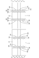
本実施形態の配線モジュール15は、複数の蓄電素子11に取り付けられて蓄電モジュール10を構成するものである。蓄電モジュール10は、例えば、電気自動車またはハイブリッド自動車等の車両の駆動源として使用される。以下では、前後方向については、図1の下方を前方、上方を後方とし、左右方向については、図1の方向を基準とし、上下方向については、図5の方向を基準として説明する。
蓄電モジュール10は、図1に示すように、複数(本実施形態では10個)の蓄電素子11と、複数の蓄電素子11に取付けられた配線モジュール15とを備えて構成されている。
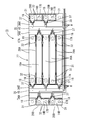
配線モジュール15は、図3に示すように、隣り合う蓄電素子11の電極端子13A,13B間を接続する複数(本実施形態では9個)の接続部材16A,16Bと、接続部材16A,16Bに重ねられる電圧検知端子18(「検知端子」の一例)と、複数の接続部材16A,16B及び電圧検知端子18を収容する合成樹脂製の絶縁プロテクタ27とを備える。
複数の接続部材16A,16Bは、左右方向に隣り合う異なる蓄電素子11の電極端子13A,13B間を接続する複数の長尺接続部材16Aと、前後方向に隣り合う異なる蓄電素子11の電極端子13A,13B間を接続し、長尺接続部材16Aよりも接続方向の長さが短い短尺接続部材16Bとを備える。
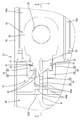
電圧検知端子18は、銅、銅合金、ステンレス鋼(SUS)、アルミニウム等の金属からなり、肉薄の金属板材にプレス機により打ち抜き加工及び曲げ加工を施して形成されており、図4に示すように、接続部材16A(16B)に重ねられてナット46で締結される被締結部19と、被締結部19に連なり接続部材16A,16Bに重ならない領域に導出されて電線Wの端末部に接続される端子導出部21とを備えている。
絶縁プロテクタ27は、絶縁性の合成樹脂製であって、図3に示すように、各接続部材16A,16Bをそれぞれ保持する複数の接続部材保持部28A,28Bと、接続部材保持部28Aと接続部材保持部28Bとの間を連結する連結部35とを備える。
具体的には、連結部35のうち接続部材保持部28Aに対して長尺接続部材16Aの接続方向に連なる位置決め部37が設けられるとともに、この位置決め部37は、前後に隣り合う接続部材保持部28Aの左方側と右方側とに交互に設けられている。また、連結部35のうち接続部材保持部28Bに対して短尺接続部材16Bの接続方向と交差する方向(本実施形態では短尺接続部材16Bの接続方向と直交する方向)に接続部材保持部28Bに連なる位置決め部37が設けられている。
なお、図4,図5は、長尺接続部材16Aの左右方向の一方に設けられた位置決め部37であるが、短尺接続部材16B側の左右に設けられた位置決め部37についても同様の構成であるため説明は省略する。ここで、短尺接続部材16B側の位置決め部37は、短尺接続部材16Bの接続方向と直交する方向に連なるため、短尺接続部材16Bの接続方向と直交する方向について位置決め部37及び電圧検知端子18を配置するためのスペースが必要とされるが、長尺接続部材16A側の位置決め部37は、長尺接続部材16Aの接続方向と直交する方向について位置決め部37及び電圧検知端子18を配置するためのスペースが少なくて済む。
本実施形態によれば、電圧検知端子18(検知端子)の端子導出部21が絶縁プロテクタ27の位置決め部37に嵌め入れられて位置決めされるため、例えば電圧検知端子18が位置ずれした際に当接して電圧検知端子18の位置ずれを所定の範囲に留める構成と異なり、端子導出部21を介して電圧検知端子18を全体として位置決めすることが可能になる。この位置決め部37による位置決めは、例えば隔壁31を貫通する通し孔に電圧検知端子18の角部を通して固定しなくても可能であるため、構成を簡素化できるとともに、隔壁31に通し孔を形成することによる絶縁性の低下を抑制することができる。よって、簡素な構成で絶縁性の低下を抑制しつつ電圧検知端子18を位置決めすることが可能となる。
このようにすれば、被締結部19の締結の際の力が電線接続部24に及ばないようにすることができる。
このようにすれば、確実に電圧検知端子18の離脱を規制することが可能になる。
このようにすれば、電圧検知端子18の位置決め部37への嵌め入れを容易に行うことができるとともに、被係合部22と係合部41の係合によって電圧検知端子18を確実に位置決めすることが可能になる。
このようにすれば、簡素な構成で端子導出部21の強度を高めることができる。また、端子導出部21の強度が高まることで、端子導出部21を位置決め部37に嵌め入れた際の位置決めを確実に行うことができる。
このようにすれば、複数の長尺接続部材16Aを並列に配置する場合に、長尺接続部材16Aの接続方向と交差する方向に導出された電圧検知端子18を位置決めする構成と比較して並列に配置された隣り合う長尺接続部材16A間のピッチを狭くすることができるため、配線モジュールを小型化することが容易になる。
本発明は上記記述及び図面によって説明した実施形態に限定されるものではなく、例えば次のような実施形態も本発明の技術的範囲に含まれる。
(1)上記実施形態では、電圧検知端子18の被係合部22を凹部とし、位置決め部37に設けられた突条である係合部41に係合させる構成としたが、これに限られず、被係合部を凸部とし、係合部を電圧検知端子18の嵌め入れ方向に延びる溝部とし、凸部を溝部に係合させるようにしてもよい。
(6)蓄電素子11の個数は、上記実施形態の個数に限られず、適宜変更することができる。また、蓄電素子11の個数に応じて配線モジュールの形状も適宜変更することができる。
11: 蓄電素子
13A,13B: 電極端子
14B: ボルト
15: 配線モジュール
16A,16B: 接続部材
18: 電圧検知端子(検知端子)
19: 被締結部
21: 端子導出部
22: 被係合部
23: 補強突部
24: 電線接続部
27: 絶縁プロテクタ
28A,28B: 接続部材保持部
31: 隔壁
35: 連結部
37: 位置決め部
39: 薄肉部
40: 厚肉部
41: 係合部
42: 撓み片
43: 係止部
45: 電線通し溝
46: ナット(締結部材)
W: 電線
Claims (6)
- 正極及び負極の電極端子を有する複数の蓄電素子の隣り合う電極端子間を接続する接続部材と、
前記接続部材を包囲する隔壁を有し、前記接続部材を収容する絶縁プロテクタと、
電線の端末部に接続され、前記接続部材に重ねられる検知端子と、を備え、
前記検知端子は、前記接続部材に重ねられて締結部材で締結される被締結部と、前記接続部材に重ならない領域に導出される端子導出部とを備え、
前記絶縁プロテクタは、前記端子導出部を嵌め入れて位置決めする位置決め部を備えている配線モジュール。 - 前記端子導出部は、前記電線の端末部に接続される電線接続部を備え、
前記位置決め部は、前記被締結部と前記電線接続部との間に形成されている請求項1に記載の配線モジュール。 - 前記位置決め部は、前記検知端子に係止して当該検知端子の離脱を規制する係止部を備えている請求項1又は請求項2に記載の配線モジュール。
- 前記端子導出部の側縁部は、凹部又は凸部からなる被係合部を備えるとともに、
前記位置決め部における前記被係合部と対応する位置には、前記被係合部に係合する突条又は溝部からなる係合部が前記検知端子の嵌め入れ方向に沿って延びている請求項1ないし請求項3のいずれか一項に記載の配線モジュール。 - 前記端子導出部は、板状であって、前記電線の接続方向に沿って延びる補強突部を有する請求項1ないし請求項4のいずれか一項に記載の配線モジュール。
- 前記絶縁プロテクタは、前記接続部材を保持する接続部材保持部を有し、前記位置決め部は、前記接続部材保持部に対して前記接続部材の接続方向に連なるように設けられている請求項1ないし請求項5のいずれか一項に記載の配線モジュール。
Priority Applications (3)
| Application Number | Priority Date | Filing Date | Title |
|---|---|---|---|
| EP13892421.2A EP2908361B1 (en) | 2013-08-28 | 2013-11-19 | Wiring module |
| US14/649,080 US9397417B2 (en) | 2013-08-28 | 2013-11-19 | Wiring module having a voltage detection terminal |
| CN201380079169.4A CN105493311B (zh) | 2013-08-28 | 2013-11-19 | 配线模块 |
Applications Claiming Priority (4)
| Application Number | Priority Date | Filing Date | Title |
|---|---|---|---|
| JP2013176644 | 2013-08-28 | ||
| JP2013-176644 | 2013-08-28 | ||
| JP2013-190658 | 2013-09-13 | ||
| JP2013190658A JP5672348B1 (ja) | 2013-08-28 | 2013-09-13 | 配線モジュール |
Publications (1)
| Publication Number | Publication Date |
|---|---|
| WO2015029267A1 true WO2015029267A1 (ja) | 2015-03-05 |
Family
ID=52573885
Family Applications (1)
| Application Number | Title | Priority Date | Filing Date |
|---|---|---|---|
| PCT/JP2013/081116 Ceased WO2015029267A1 (ja) | 2013-08-28 | 2013-11-19 | 配線モジュール |
Country Status (5)
| Country | Link |
|---|---|
| US (1) | US9397417B2 (ja) |
| EP (2) | EP3098878B1 (ja) |
| JP (1) | JP5672348B1 (ja) |
| CN (1) | CN105493311B (ja) |
| WO (1) | WO2015029267A1 (ja) |
Families Citing this family (8)
| Publication number | Priority date | Publication date | Assignee | Title |
|---|---|---|---|---|
| JP6186922B2 (ja) * | 2013-06-18 | 2017-08-30 | 住友電装株式会社 | 配線モジュール |
| JP6427136B2 (ja) | 2016-04-27 | 2018-11-21 | 矢崎総業株式会社 | 印刷回路体 |
| JP6490650B2 (ja) | 2016-10-17 | 2019-03-27 | 矢崎総業株式会社 | 電圧検出端子の固定構造 |
| WO2018230523A1 (ja) * | 2017-06-16 | 2018-12-20 | 株式会社Gsユアサ | 蓄電装置 |
| JP2019032960A (ja) * | 2017-08-07 | 2019-02-28 | 矢崎エナジーシステム株式会社 | 電池パック |
| JP6414361B1 (ja) * | 2018-03-30 | 2018-10-31 | 株式会社オートネットワーク技術研究所 | 接続モジュール |
| KR102750490B1 (ko) * | 2019-03-15 | 2025-01-03 | 주식회사 엘지에너지솔루션 | 전지 모듈 및 그 제조 방법 |
| CN112447407A (zh) * | 2019-08-30 | 2021-03-05 | 厦门万明电子有限公司 | 一种陶瓷电容器 |
Citations (8)
| Publication number | Priority date | Publication date | Assignee | Title |
|---|---|---|---|---|
| WO2012127962A1 (ja) * | 2011-03-18 | 2012-09-27 | 株式会社オートネットワーク技術研究所 | 配線モジュール |
| JP2013016381A (ja) * | 2011-07-05 | 2013-01-24 | Auto Network Gijutsu Kenkyusho:Kk | 電池配線モジュール |
| JP2013016382A (ja) | 2011-07-05 | 2013-01-24 | Auto Network Gijutsu Kenkyusho:Kk | 電池配線モジュール |
| WO2013069525A1 (ja) * | 2011-11-11 | 2013-05-16 | 株式会社オートネットワーク技術研究所 | 電池配線モジュール |
| JP2013105571A (ja) * | 2011-11-11 | 2013-05-30 | Auto Network Gijutsu Kenkyusho:Kk | 電池配線モジュール |
| WO2013111526A1 (en) * | 2012-01-27 | 2013-08-01 | Yazaki Corporation | Terminal fixation structure and power supply device using the same |
| JP2013161749A (ja) * | 2012-02-08 | 2013-08-19 | Auto Network Gijutsu Kenkyusho:Kk | 配線モジュール |
| JP2013162569A (ja) * | 2012-02-02 | 2013-08-19 | Auto Network Gijutsu Kenkyusho:Kk | 電池配線モジュール |
Family Cites Families (12)
| Publication number | Priority date | Publication date | Assignee | Title |
|---|---|---|---|---|
| JP5536382B2 (ja) * | 2009-07-08 | 2014-07-02 | 矢崎総業株式会社 | 電源装置 |
| JP5813302B2 (ja) * | 2009-09-07 | 2015-11-17 | 矢崎総業株式会社 | バスバモジュール、及び、このバスバモジュールを備えた電源装置 |
| JP5550290B2 (ja) * | 2009-09-17 | 2014-07-16 | 矢崎総業株式会社 | 電線配索体、バスバモジュール、及び、電源装置 |
| JP5450640B2 (ja) * | 2009-10-06 | 2014-03-26 | 矢崎総業株式会社 | 電池接続体 |
| JP5733613B2 (ja) | 2011-03-11 | 2015-06-10 | 株式会社リコー | 現像装置および画像形成装置 |
| JP5737046B2 (ja) * | 2011-08-10 | 2015-06-17 | 株式会社オートネットワーク技術研究所 | 電池配線モジュール |
| JP5673465B2 (ja) * | 2011-09-15 | 2015-02-18 | 株式会社オートネットワーク技術研究所 | 電池配線モジュール |
| JP5834769B2 (ja) | 2011-10-26 | 2015-12-24 | 株式会社オートネットワーク技術研究所 | 電池用配線モジュール |
| JP5875107B2 (ja) * | 2011-12-07 | 2016-03-02 | 矢崎総業株式会社 | 電池接続体 |
| JP5881207B2 (ja) * | 2012-02-09 | 2016-03-09 | 矢崎総業株式会社 | 電池接続体 |
| JP6068059B2 (ja) | 2012-08-30 | 2017-01-25 | 矢崎総業株式会社 | バスバモジュール |
| JP6103305B2 (ja) | 2013-09-13 | 2017-03-29 | 株式会社オートネットワーク技術研究所 | 配線モジュール |
-
2013
- 2013-09-13 JP JP2013190658A patent/JP5672348B1/ja not_active Expired - Fee Related
- 2013-11-19 WO PCT/JP2013/081116 patent/WO2015029267A1/ja not_active Ceased
- 2013-11-19 CN CN201380079169.4A patent/CN105493311B/zh not_active Expired - Fee Related
- 2013-11-19 EP EP16177739.6A patent/EP3098878B1/en not_active Not-in-force
- 2013-11-19 US US14/649,080 patent/US9397417B2/en not_active Expired - Fee Related
- 2013-11-19 EP EP13892421.2A patent/EP2908361B1/en not_active Not-in-force
Patent Citations (8)
| Publication number | Priority date | Publication date | Assignee | Title |
|---|---|---|---|---|
| WO2012127962A1 (ja) * | 2011-03-18 | 2012-09-27 | 株式会社オートネットワーク技術研究所 | 配線モジュール |
| JP2013016381A (ja) * | 2011-07-05 | 2013-01-24 | Auto Network Gijutsu Kenkyusho:Kk | 電池配線モジュール |
| JP2013016382A (ja) | 2011-07-05 | 2013-01-24 | Auto Network Gijutsu Kenkyusho:Kk | 電池配線モジュール |
| WO2013069525A1 (ja) * | 2011-11-11 | 2013-05-16 | 株式会社オートネットワーク技術研究所 | 電池配線モジュール |
| JP2013105571A (ja) * | 2011-11-11 | 2013-05-30 | Auto Network Gijutsu Kenkyusho:Kk | 電池配線モジュール |
| WO2013111526A1 (en) * | 2012-01-27 | 2013-08-01 | Yazaki Corporation | Terminal fixation structure and power supply device using the same |
| JP2013162569A (ja) * | 2012-02-02 | 2013-08-19 | Auto Network Gijutsu Kenkyusho:Kk | 電池配線モジュール |
| JP2013161749A (ja) * | 2012-02-08 | 2013-08-19 | Auto Network Gijutsu Kenkyusho:Kk | 配線モジュール |
Non-Patent Citations (1)
| Title |
|---|
| See also references of EP2908361A4 |
Also Published As
| Publication number | Publication date |
|---|---|
| JP5672348B1 (ja) | 2015-02-18 |
| US20150318626A1 (en) | 2015-11-05 |
| EP2908361B1 (en) | 2017-03-22 |
| US9397417B2 (en) | 2016-07-19 |
| EP3098878A1 (en) | 2016-11-30 |
| EP3098878B1 (en) | 2017-12-27 |
| CN105493311B (zh) | 2018-04-17 |
| CN105493311A (zh) | 2016-04-13 |
| EP2908361A1 (en) | 2015-08-19 |
| JP2015064927A (ja) | 2015-04-09 |
| EP2908361A4 (en) | 2016-03-16 |
Similar Documents
| Publication | Publication Date | Title |
|---|---|---|
| WO2015029267A1 (ja) | 配線モジュール | |
| US9209550B2 (en) | Battery wiring module | |
| US8981239B2 (en) | Capacitor module | |
| JP5494748B2 (ja) | 電池用配線モジュール | |
| JP5817535B2 (ja) | 配線モジュール | |
| JP6075150B2 (ja) | 配線モジュール | |
| WO2011021614A1 (ja) | 電源装置及び電池接続体 | |
| JP5779513B2 (ja) | 電池配線モジュール | |
| WO2014156580A1 (ja) | 配線モジュール | |
| WO2012108514A1 (ja) | バスバモジュール | |
| WO2016098607A1 (ja) | 電池配線モジュール | |
| CN101997106A (zh) | 电源设备 | |
| US10559803B2 (en) | Bus bar holding structure | |
| JP2012059500A (ja) | 電池モジュール | |
| WO2014192644A1 (ja) | バスバーモジュール及び電源装置 | |
| EP2892087B1 (en) | Structure for holding voltage detecting terminal | |
| WO2015163126A1 (ja) | 配線モジュール、配線モジュール中間体、及び配線モジュールの製造方法 | |
| WO2013008558A1 (ja) | 電池配線モジュール | |
| WO2015015667A1 (ja) | 配線モジュール | |
| CN109478629B (zh) | 布线模块 | |
| US10464510B2 (en) | Power supply device and method for producing the same | |
| WO2015163113A1 (ja) | 配線モジュール | |
| JP2015035323A (ja) | バスバモジュール | |
| JP2016096674A (ja) | 電気接続箱 | |
| US9608251B2 (en) | Battery module with electrode identifier |
Legal Events
| Date | Code | Title | Description |
|---|---|---|---|
| WWE | Wipo information: entry into national phase |
Ref document number: 201380079169.4 Country of ref document: CN |
|
| REEP | Request for entry into the european phase |
Ref document number: 2013892421 Country of ref document: EP |
|
| WWE | Wipo information: entry into national phase |
Ref document number: 2013892421 Country of ref document: EP |
|
| 121 | Ep: the epo has been informed by wipo that ep was designated in this application |
Ref document number: 13892421 Country of ref document: EP Kind code of ref document: A1 |
|
| WWE | Wipo information: entry into national phase |
Ref document number: 14649080 Country of ref document: US |
|
| NENP | Non-entry into the national phase |
Ref country code: DE |