WO2015029585A1 - 内視鏡用光コネクタ - Google Patents
内視鏡用光コネクタ Download PDFInfo
- Publication number
- WO2015029585A1 WO2015029585A1 PCT/JP2014/067578 JP2014067578W WO2015029585A1 WO 2015029585 A1 WO2015029585 A1 WO 2015029585A1 JP 2014067578 W JP2014067578 W JP 2014067578W WO 2015029585 A1 WO2015029585 A1 WO 2015029585A1
- Authority
- WO
- WIPO (PCT)
- Prior art keywords
- waveguide
- exchange
- insertion port
- holding
- replacement
- Prior art date
- Legal status (The legal status is an assumption and is not a legal conclusion. Google has not performed a legal analysis and makes no representation as to the accuracy of the status listed.)
- Ceased
Links
Images


Classifications
-
- G—PHYSICS
- G02—OPTICS
- G02B—OPTICAL ELEMENTS, SYSTEMS OR APPARATUS
- G02B6/00—Light guides; Structural details of arrangements comprising light guides and other optical elements, e.g. couplings
- G02B6/24—Coupling light guides
- G02B6/42—Coupling light guides with opto-electronic elements
- G02B6/4201—Packages, e.g. shape, construction, internal or external details
- G02B6/4219—Mechanical fixtures for holding or positioning the elements relative to each other in the couplings; Alignment methods for the elements, e.g. measuring or observing methods especially used therefor
- G02B6/4228—Passive alignment, i.e. without a detection of the degree of coupling or the position of the elements
- G02B6/423—Passive alignment, i.e. without a detection of the degree of coupling or the position of the elements using guiding surfaces for the alignment
-
- A—HUMAN NECESSITIES
- A61—MEDICAL OR VETERINARY SCIENCE; HYGIENE
- A61B—DIAGNOSIS; SURGERY; IDENTIFICATION
- A61B1/00—Instruments for performing medical examinations of the interior of cavities or tubes of the body by visual or photographical inspection, e.g. endoscopes; Illuminating arrangements therefor
- A61B1/00112—Connection or coupling means
- A61B1/00121—Connectors, fasteners and adapters, e.g. on the endoscope handle
- A61B1/00126—Connectors, fasteners and adapters, e.g. on the endoscope handle optical, e.g. for light supply cables
-
- G—PHYSICS
- G02—OPTICS
- G02B—OPTICAL ELEMENTS, SYSTEMS OR APPARATUS
- G02B23/00—Telescopes, e.g. binoculars; Periscopes; Instruments for viewing the inside of hollow bodies; Viewfinders; Optical aiming or sighting devices
- G02B23/24—Instruments or systems for viewing the inside of hollow bodies, e.g. fibrescopes
- G02B23/26—Instruments or systems for viewing the inside of hollow bodies, e.g. fibrescopes using light guides
-
- G—PHYSICS
- G02—OPTICS
- G02B—OPTICAL ELEMENTS, SYSTEMS OR APPARATUS
- G02B6/00—Light guides; Structural details of arrangements comprising light guides and other optical elements, e.g. couplings
- G02B6/24—Coupling light guides
- G02B6/36—Mechanical coupling means
- G02B6/3616—Holders, macro size fixtures for mechanically holding or positioning fibres, e.g. on an optical bench
-
- G—PHYSICS
- G02—OPTICS
- G02B—OPTICAL ELEMENTS, SYSTEMS OR APPARATUS
- G02B6/00—Light guides; Structural details of arrangements comprising light guides and other optical elements, e.g. couplings
- G02B6/24—Coupling light guides
- G02B6/36—Mechanical coupling means
- G02B6/38—Mechanical coupling means having fibre to fibre mating means
- G02B6/3807—Dismountable connectors, i.e. comprising plugs
- G02B6/381—Dismountable connectors, i.e. comprising plugs of the ferrule type, e.g. fibre ends embedded in ferrules, connecting a pair of fibres
- G02B6/3825—Dismountable connectors, i.e. comprising plugs of the ferrule type, e.g. fibre ends embedded in ferrules, connecting a pair of fibres with an intermediate part, e.g. adapter, receptacle, linking two plugs
-
- G—PHYSICS
- G02—OPTICS
- G02B—OPTICAL ELEMENTS, SYSTEMS OR APPARATUS
- G02B6/00—Light guides; Structural details of arrangements comprising light guides and other optical elements, e.g. couplings
- G02B6/24—Coupling light guides
- G02B6/36—Mechanical coupling means
- G02B6/38—Mechanical coupling means having fibre to fibre mating means
- G02B6/3807—Dismountable connectors, i.e. comprising plugs
- G02B6/3833—Details of mounting fibres in ferrules; Assembly methods; Manufacture
- G02B6/3846—Details of mounting fibres in ferrules; Assembly methods; Manufacture with fibre stubs
-
- G—PHYSICS
- G02—OPTICS
- G02B—OPTICAL ELEMENTS, SYSTEMS OR APPARATUS
- G02B6/00—Light guides; Structural details of arrangements comprising light guides and other optical elements, e.g. couplings
- G02B6/24—Coupling light guides
- G02B6/36—Mechanical coupling means
- G02B6/38—Mechanical coupling means having fibre to fibre mating means
- G02B6/3807—Dismountable connectors, i.e. comprising plugs
- G02B6/3873—Connectors using guide surfaces for aligning ferrule ends, e.g. tubes, sleeves, V-grooves, rods, pins, balls
- G02B6/3885—Multicore or multichannel optical connectors, i.e. one single ferrule containing more than one fibre, e.g. ribbon type
-
- G—PHYSICS
- G02—OPTICS
- G02B—OPTICAL ELEMENTS, SYSTEMS OR APPARATUS
- G02B6/00—Light guides; Structural details of arrangements comprising light guides and other optical elements, e.g. couplings
- G02B6/24—Coupling light guides
- G02B6/36—Mechanical coupling means
- G02B6/38—Mechanical coupling means having fibre to fibre mating means
- G02B6/3807—Dismountable connectors, i.e. comprising plugs
- G02B6/3833—Details of mounting fibres in ferrules; Assembly methods; Manufacture
- G02B6/3853—Lens inside the ferrule
-
- G—PHYSICS
- G02—OPTICS
- G02B—OPTICAL ELEMENTS, SYSTEMS OR APPARATUS
- G02B6/00—Light guides; Structural details of arrangements comprising light guides and other optical elements, e.g. couplings
- G02B6/24—Coupling light guides
- G02B6/36—Mechanical coupling means
- G02B6/38—Mechanical coupling means having fibre to fibre mating means
- G02B6/3807—Dismountable connectors, i.e. comprising plugs
- G02B6/3873—Connectors using guide surfaces for aligning ferrule ends, e.g. tubes, sleeves, V-grooves, rods, pins, balls
- G02B6/3882—Connectors using guide surfaces for aligning ferrule ends, e.g. tubes, sleeves, V-grooves, rods, pins, balls using rods, pins or balls to align a pair of ferrule ends
Definitions
- the first waveguide disposed in the connection connector of the endoscope and the second waveguide disposed in the insertion port of the light source device to which the connection connector is connected are made optical.
- the present invention relates to an endoscope optical connector to be coupled.
- Patent Document 1 An optical connector that optically couples optical fibers is disclosed in Patent Document 1, for example.
- This optical connector is a single-core connector type.
- the end portion of the optical fiber is exposed in a normal state, and the end portion can be replaced when the end portion is damaged.
- Each optical connector has an original ferrule of a main body holding one optical fiber and an exchange ferrule holding the other optical fiber.
- the main body has a spring that presses the original ferrule.
- the optical connectors are optically connected to each other by an adapter that holds the sleeve inside.
- the flange of the replacement ferrule hits the exterior of the optical connector, and the original ferrule is pressed against the replacement ferrule by the spring.
- a pressing force that presses each other is applied to the original ferrule and the exchange ferrule
- a pressing force that presses each other is applied to the end face of one optical fiber and the end face of the other optical fiber.
- the replacement ferrule of one optical connector abuts against the replacement ferrule of the other optical connector inside the sleeve.
- the original ferrule is disposed coaxially with the exchange ferrule.
- the original ferrule is pressed against the replacement ferrule by a spring.
- a pressing force that presses each other is applied to the original ferrule and the exchange ferrule
- a pressing force that presses each other is applied to the end face of one optical fiber and the end face of the other optical fiber.
- the exchange ferrules press each other with a spring through the original ferrule. Therefore, the optical fiber in one exchange ferrule and the optical fiber in the other exchange ferrule are optically coupled directly to each other.
- Patent Document 1 when one optical connector is pulled out from the sleeve, there is a possibility that the pressing force is not always maintained between the replacement ferrule and the original ferrule. Specifically, it is assumed that one optical connector is pulled out of the sleeve from a state in which one optical connector is connected to the other optical connector. In this case, the pressing of the replacement ferrule in one optical connector and the replacement ferrule in the other optical connector is released with the spring contracted. When one of the optical connectors is further pulled out from this state, the replacement ferrule is pulled out from the sleeve. As a result, a force acts on the exchange ferrule and the original ferrule in one of the optical connectors in the direction of detachment from each other.
- the sealed state is temporarily released. Enters between the end face of one optical fiber and the end face of the other optical fiber. As a result, the optical coupling efficiency is lowered. Moreover, the foreign matter that has entered damages the optical coupling portion indicating the end face of one optical fiber and the end face of the other optical fiber, resulting in a decrease in optical coupling efficiency.
- the entry of foreign matter into the optical coupling part due to the temporary release of the sealed state is a direct factor of reducing the optical coupling efficiency, and the optical coupling efficiency is reduced by damaging the optical coupling part. It becomes an indirect factor.
- the optical coupling part when the optical coupling part is damaged by a foreign object, the optical coupling part can be easily replaced, and when it is not connected, when connected, when switching from a disconnected state to a connected state, and from a connected state to a disconnected state There is a need for a high sealing property that prevents foreign matter from entering the optical coupling portion at the time of switching.
- the present invention has been made in view of these circumstances, and when the optical coupling portion is damaged by a foreign object, the optical coupling portion can be easily replaced, and can be connected from a disconnected state, a connected state, and a disconnected state. It is an object of the present invention to provide an optical connector for an endoscope having high sealing performance that prevents foreign matter from entering the optical coupling portion at the time of switching to a state and at the time of switching from a connected state to a non-connected state. .
- One aspect of the optical connector for an endoscope of the present invention includes a first holding member that holds the first waveguide inside, a second holding member that holds the second waveguide inside, and the first holding member.
- the first maintaining is such that a waveguide is optically coupled to the first waveguide and the second waveguide.
- FIG. 1 is a perspective view of an endoscope apparatus on which an optical connector according to a first embodiment of the present invention is mounted.
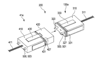
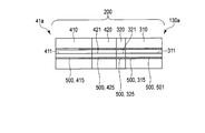
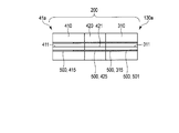
- FIG. 2A is a perspective view of the optical connector.
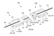
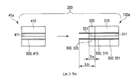
- 2B is an exploded cross-sectional perspective view of the optical connector shown in FIG. 2A.
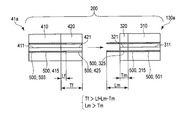
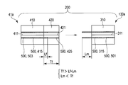
- FIG. 2C is a diagram illustrating the relationship between the lengths Tm, Lm, Tf, and Lf, and the first exchange waveguide in a state where the first waveguide is optically coupled to the first exchange waveguide.
- FIG. 4 is a diagram showing a state where the optical fiber is optically uncoupled from the second exchange waveguide.
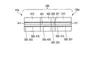
- FIG. 2D is a diagram illustrating a state in which the first exchange waveguide is optically coupled to the second exchange waveguide from the state illustrated in FIG. 2C.
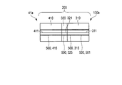
- FIG. 3A is a diagram illustrating a first modification of the optical connector and illustrating the relationship between the lengths Tm, Lm, and Tf, and the first waveguide is optically coupled to the first exchange waveguide. It is a figure which shows the state which the 1st exchange waveguide is optically uncoupled with the 2nd exchange waveguide in a state.
- FIG. 3B is a diagram illustrating a state in which the first exchange waveguide is optically coupled to the second exchange waveguide from the state illustrated in FIG. 3A.
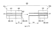
- FIG. 4A is a diagram showing a second modification of the optical connector and showing the relationship between the lengths Tm and Lm, in a state where the first waveguide is optically coupled to the first exchange waveguide.
- FIG. 3A is a diagram illustrating a first modification of the optical connector and illustrating the relationship between the lengths Tm, Lm, in a state where the first waveguide is optically coupled to the first exchange waveguide.
- FIG. 5 is a diagram showing a state where the first exchange waveguide is optically uncoupled from the second waveguide.
- FIG. 4B is a diagram illustrating a state in which the first exchange waveguide is optically coupled to the second waveguide from the state illustrated in FIG. 4A.
- FIG. 5A is a diagram showing a third modification of the optical connector and showing the relationship between the lengths Lm and Tf, in which the first waveguide is optically uncoupled from the second exchanged waveguide.
- FIG. FIG. 5B is a diagram illustrating a state in which the first waveguide is optically coupled to the second exchange waveguide from the state illustrated in FIG. 5A.
- FIG. 6A is a diagram showing a fourth modification of the optical connector and showing the relationship between the lengths Lm, Tf, and Lf.
- the first waveguide is optically uncoupled from the second exchange waveguide.
- FIG. 6B is a diagram illustrating a state in which the first waveguide is optically coupled to the second exchange waveguide from the state illustrated in FIG. 6A.
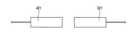
- FIG. 7A is a diagram illustrating a fifth modification of the optical connector and illustrating that the exchange waveguide includes a tapered fiber.
- FIG. 7B is a diagram illustrating a fifth modification of the optical connector, in which the exchange waveguide includes a lens.
- FIG. 8 is a diagram illustrating a sixth modification of the optical connector, in which the hook portion has a protrusion.
- An endoscope apparatus 100 as shown in FIG. 1 is disposed in, for example, an examination room or an operating room. As shown in FIG. 1, an endoscope apparatus 100 images an endoscope 10 that images a body cavity (lumen) of a patient and the like, and an image of the body cavity of a patient and the like imaged by the endoscope 10.
- An image processing apparatus 110 for example, a video processor for processing is included.
- the endoscope apparatus 100 is connected to the image processing apparatus 110, and includes a display unit 120 that displays an image in a body cavity of a patient or the like imaged by the endoscope 10 and image-processed by the image processing apparatus 110, and an endoscope And a light source device 130 that emits light for illumination light emitted from the mirror 10.
- the endoscope 10 is connected to a hollow elongated insertion portion 20 that is inserted into a lumen such as a body cavity, for example, an operation portion 30 that operates the endoscope 10, and an operation portion 30. And a universal cord 41 extending from the side surface of the operation unit 30.
- the universal cord 41 has a connection connector 41 a that can be attached to and detached from the image processing device 110 and the light source device 130.
- the connection connector 41a connects the endoscope 10 and various devices (the image processing device 110 and the light source device 130), and is arranged to transmit and receive data between them.
- the connection connector 41a includes an electrical connection unit (not shown) provided for controlling the imaging unit provided at the distal end of the insertion unit 20, and an air supply (not shown) provided for air supply / water supply. It has a connection part for water supply, and a part of optical connector for endoscopes arranged for light emitted from light source device 130.
- the image processing device 110 functions as a control device that controls the entire endoscope device 100 including the endoscope 10, the display unit 120, and the light source device 130.
- the image processing device 110 and the light source device 130 are electrically connected to each other.
- the image processing device 110 and the light source device 130 are detachably connected to the endoscope 10 via a connection connector 41a.
- optical connector 200 Optical connector for endoscope (hereinafter, optical connector 200)]
- the optical connector 200 shown in FIG. 2A is built in the insertion port 130a (see FIG. 1) of the light source device 130 into which the connection connector 41a is inserted, and inside the connection connector 41a.
- the optical connector 200 is replaceable with the first holding member 310 that holds the first waveguide 311 inside and the first holding member 310. And a first replacement member 320.
- the optical connector 200 further includes a first attachment member 330 that attaches the first exchange member 320 to the first holding member 310 by, for example, pressing the first exchange member 320 against the first holding member 310. ing.
- the optical connector 200 can be exchanged for the second holding member 410 that holds the second waveguide 411 and the second holding member 410.
- the optical connector 200 further includes a second mounting member 430 that presses the second replacement member 420 against the second holding member 410, for example, and attaches the second replacement member 420 to the second holding member 410. ing.
- the first waveguide 311 is optically coupled to the first exchange waveguide 321 of the first exchange member 320.
- the second waveguide 411 is optically coupled to the second exchange waveguide 421 of the second exchange member 420, and the first exchange waveguide 321 is optically coupled to the second exchange waveguide 421.
- it further includes a positioning mechanism 500 that positions the first holding member 310, the second holding member 410, the first exchange member 320, and the second exchange member 420 relative to each other.
- the first holding member 310 side including the first replacement member 320 and the first attachment member 330 is, for example, a convex shape and is built in the insertion port 130a of the light source device 130 into which the connection connector 41a is inserted.
- the second holding member 410 side including the second replacement member 420 and the second mounting member 430 is, for example, a concave shape and is built in the connection connector 41a inserted into the insertion port 130a.
- the first waveguide 311, the second waveguide 411, the first exchange waveguide 321, and the second exchange waveguide 421 may be the same number.
- the first waveguide 311 has, for example, at least one optical fiber. This is the same for the second waveguide 411, the first exchange waveguide 321, and the second exchange waveguide 421. A plurality of these waveguides may be provided.
- the optical fiber may be single-core or multi-core. May be.
- the first holding member 310 has a ferrule formed by, for example, resin molding. As shown in FIG. 2B, the first holding member 310 includes an insertion port portion 313 into which the first waveguide 311 is inserted and an insertion port portion into which a first positioning member 501 described later of the positioning mechanism 500 is inserted. 315.
- the insertion port 313 is disposed along the longitudinal axis direction of the first holding member 310 and penetrates the first holding member 310 in the longitudinal axis direction.
- the first holding member 310 holds the first waveguide 311 by the first waveguide 311 being inserted into the insertion port portion 313 and bonded and fixed to the insertion port portion 313, for example.
- the insertion port 313 is disposed at the center of the first holding member 310.
- the end surface of the first holding member 310 is disposed on the same plane as the end surface of the first waveguide 311, and the end surface of the first holding member 310 and the end surface of the first waveguide 311 are arranged.
- the end surface of the first holding member 310 can be polished together with the end surface of the first waveguide 311, for example. ing.
- This end face indicates, for example, a face on the side where the first replacement member 320 is attached.
- the insertion port portion 315 is disposed along the longitudinal axis direction of the first holding member 310 and penetrates the first holding member 310 in the longitudinal axis direction.
- the insertion port 315 is disposed on both sides of the insertion port 313.
- two insertion openings 315 may be disposed symmetrically with respect to the first waveguide 311.
- the insertion port 315 is formed simultaneously with the insertion port 313 so as to be positioned relative to the insertion port 313.
- First replacement member 320 As shown in FIGS. 2A and 2B, the configuration of the first replacement member 320 is substantially the same as the configuration of the first holding member 310, and thus detailed description thereof is omitted.
- a waveguide corresponding to the first waveguide 311 is referred to as a first exchange waveguide 321
- an insertion port corresponding to the insertion port 313 is referred to as a replacement insertion port 323, and an insertion port corresponding to the insertion port 315. This portion is referred to as an exchange insertion port portion 325.
- the first exchange member 320 holds the first exchange waveguide 321 that is optically coupled to the first waveguide 311 inside the first exchange member 320.
- first exchange waveguides 321 as the first waveguides 311 are arranged, the same number of exchange insertion openings 323 as the insertion openings 313, and the exchange insertion openings 325 are the insertion openings 315. The same number is arranged.
- the replacement insertion port portion 325 is formed simultaneously with the replacement insertion port portion 323 so as to be positioned relative to the replacement insertion port portion 323.
- the replacement insertion port portion 323 is formed so as to be positioned relative to the insertion port portion 313.
- the replacement insertion port portion 325 is formed so as to be positioned relative to the insertion port portion 315.
- the first replacement member 320 is preferably formed in a separate process from the first holding member 310 in consideration of the exchangeability of the first replacement member 320.
- the first replacement member 320 and the first holding member 310 may be formed as a single body, and may be divided after being formed.
- the cross-sectional area A1 of the first holding member 310 and the cross-sectional area A2 of the first replacement member 320 are the same as the cross-sectional area A2.
- the size of the cross-sectional area A1 is the same as the size of the cross-sectional area A2.
- the cross-sectional area A1 is a surface obtained by cutting the first holding member 310 perpendicularly to the longitudinal axis of the first holding member 310.
- the cross-sectional area A2 is a surface obtained by cutting the first replacement member 320 perpendicularly to the central axis of the first replacement member 320 disposed coaxially with the longitudinal axis of the first holding member 310.
- the end face of the first exchange member 320 is disposed on the same plane as the end face of the first exchange waveguide 321.
- the end face of the first exchange member 320 is the first exchange waveguide.
- polishing is possible. This polishing is possible on both end faces of the first replacement member 320 in the axial direction of the optical connector 200.
- the both end surfaces have an end surface in contact with the end surface of the first holding member 310 and an end surface in contact with the end surface of the second replacement member 420.
- the first replacement member 320 has the smooth end surface of the first replacement member 320 in contact with and in close contact with the smooth end surface of the first holding member 310.
- One waveguide 311 is arranged on the same straight line in the axial direction of the first exchange waveguide 321 and the optical connector 200, and the first waveguide 311 is optically coupled to the first exchange waveguide 321;
- the insertion port portion 315 is attached to the first holding member 310 so as to communicate with the replacement insertion port portion 325 in the axial direction of the optical connector 200.
- the first replacement member 320 is between the second replacement member 420 and the first holding member 310 in the axial direction of the optical connector 200. Intervene.
- the length of the first replacement member 320 is different from the length of the second replacement member 420.
- the length of the member 420 is shorter.
- the configuration of the first replacement member 320 is different from the configuration of the first holding member 310 as follows. As shown in FIGS. 2A and 2B, the first replacement member 320 is formed on the peripheral surface of the first replacement member 320, and the first hooking portion 327 to which the tip end portion of the first mounting member 330 is hooked is formed. Have. The first hooking portion 327 is disposed symmetrically with respect to the first exchange waveguide 321. The first hook portion 327 has, for example, a first groove portion formed over the entire side surface of the first replacement member 320. The first groove has, for example, a concave cross section. For example, the first groove is recessed perpendicularly to the side surface of the first replacement member 320.
- First mounting member 330 As shown in FIGS. 2A and 2B, the first attachment member 330 is centered on the first waveguide 311 disposed on the first holding member 310 on the side where the first replacement member 320 is attached. Are arranged on the first holding member 310 on the side to be attached. The first attachment member 330 only needs to be arranged point-symmetrically around the first waveguide 311. The first attachment member 330 may be disposed around the first waveguide 311 so as to surround the first waveguide 311 from four directions. The first attachment member 330 has a base end portion fixed to each peripheral surface of the first holding member 310 on the side to which the first replacement member 320 is attached, for example, by adhesion.
- the first attachment member 330 presses the first replacement member 320 toward the first holding member 310 that is the attachment side so that the first replacement member 320 is attached to the first holding member 310. To do. For this reason, as shown in FIGS. 2A and 2B, the first attachment member 330 is disposed at the tip of the first attachment member 330, and the first catching portion 327 of the first replacement member 320. It has the 1st nail
- the pressing force acts in the axial direction of the optical connector 200.
- the first claw portion 331 closely contacts the end surface of the first holding member 310 including the first waveguide 311 and the end surface of the first replacement member 320 including the first exchange waveguide 321 by pressing force. The sealed state is maintained at these end faces.
- the first claw portion 331 has, for example, a leaf spring portion.
- the first claw portion 331 has a part that is bent so as to be caught by the first catch portion 327. This part is formed so that it may protrude in the direction orthogonal to the axial direction of the 1st attachment member 330, for example.
- the configuration of the second holding member 410 is substantially the same as the configuration of the first holding member 310, and thus detailed description thereof is omitted.
- An insertion port portion corresponding to the insertion port portion 313 is referred to as an insertion port portion 413, and an insertion port portion corresponding to the insertion port portion 315 is referred to as an insertion port portion 415.
- the configuration of the second replacement member 420 is substantially the same as the configuration of the first replacement member 320, and thus detailed description thereof is omitted.
- An exchange waveguide corresponding to the first exchange waveguide 321 is referred to as a second exchange waveguide 421
- an exchange insertion port corresponding to the exchange insertion port 323 is referred to as an exchange insertion port 423
- an exchange insertion port 325 is referred to as an exchange insertion port 423
- the replacement insertion port portion corresponding to 1 is referred to as the replacement insertion port portion 425
- the hook portion corresponding to the first hook portion 327 is referred to as the second hook portion 427
- the groove portion corresponding to the first groove portion is the second groove portion. Called.
- the replacement insertion port portion 425 is formed simultaneously with the replacement insertion port portion 423 so as to be positioned relative to the replacement insertion port portion 423.
- the replacement insertion slot 423 is formed so as to be positioned relative to the insertion slot 413.
- the replacement insertion port 425 is formed so as to be positioned relative to the insertion port 415.
- the second exchange member 420 is preferably formed in a separate process from the second holding member 410 in consideration of the exchangeability of the second exchange member 420.
- the second replacement member 420 and the second holding member 410 may be formed as a single body, and may be divided after being formed.
- the cross-sectional area B1 of the second holding member 410 and the cross-sectional area B2 of the second replacement member 420 are the same as the cross-sectional area B2.
- the size of the cross-sectional area B1 is the same as the size of the cross-sectional area B2.
- the shape of the cross-sectional area B1 is the same as the shape of the cross-sectional area A1
- the size of the cross-sectional area B1 is the same as the size of the cross-sectional area A1.
- the cross-sectional area B1 is a surface obtained by cutting the second holding member 410 perpendicularly to the longitudinal axis of the second holding member 410.
- the cross-sectional area B2 is a surface obtained by cutting the second replacement member 420 perpendicularly to the central axis of the second replacement member 420 disposed coaxially with the longitudinal axis of the second holding member 410.
- the end face of the second exchange member 420 is disposed on the same plane as the end face of the second exchange waveguide 421, and the end face of the second exchange member 420 and the second face In the state where the second exchange member 420 holds the second exchange waveguide 421 so that the end face of the other exchange waveguide 421 is smoothed, the end face of the second exchange member 420 is the second exchange waveguide.
- polishing is possible together with the end face of 421. This polishing is possible on both end faces of the second replacement member 420 in the axial direction of the optical connector 200.
- the both end surfaces have an end surface that contacts the end surface of the second holding member 410 and an end surface that contacts the end surface of the first replacement member 320.
- the second replacement member 420 has a smooth end surface in contact with and in close contact with the smooth end surface of the second holding member 410.
- Two waveguides 411 are arranged on the same straight line in the axial direction of the second exchange waveguide 421 and the optical connector 200, and the second waveguide 411 is optically coupled to the second exchange waveguide 421;
- the insertion port portion 415 is attached to the second holding member 410 so as to communicate with the replacement insertion port portion 425 in the axial direction of the optical connector 200.
- the second replacement member 420 is between the first replacement member 320 and the second holding member 410 in the axial direction of the optical connector 200.
- the relative position between the second holding member 410 and the second replacement member 420 is substantially the same as the relative position between the first holding member 310 and the first replacement member 320.
- the configuration of the second mounting member 430 is substantially the same as the configuration of the first mounting member 330, and thus detailed description thereof is omitted.
- a claw portion corresponding to the first claw portion 331 is referred to as a second claw portion 431.
- the second mounting member 430 is disposed on the second holding member 410 in a state substantially the same as the state in which the first mounting member 330 is disposed on the first holding member 310.
- the second mounting member 430 causes the second holding member 410 to have substantially the same function as that of the first mounting member 330 in the same manner as the action of the first mounting member 330 with respect to the first holding member 310. .
- the positioning mechanism 500 includes an insertion port portion 315 that is a first holding side insertion port portion and an exchange insertion that is a first replacement side insertion port portion. And a mouth portion 325.
- the positioning mechanism 500 further includes an insertion port portion 415 that is a second holding side insertion port portion and an exchange insertion port portion 425 that is a second replacement side insertion port portion.
- the positioning mechanism 500 is engaged with the first positioning member 501 that engages with the insertion port portion 315, the replacement insertion port portion 325, and the replacement insertion port portion 425, and the insertion port portion 415 and the replacement insertion port portion 425.
- the first positioning member 501 has a pin, for example.
- the second positioning member 503 has a pin.
- the first exchange waveguide 321 is optically coupled to the second exchange waveguide 421 while the first waveguide 311 is optically coupled to the first exchange waveguide 321.
- the first positioning member 501 is inserted into the insertion port portion 315 so that the distal end portion of the first positioning member 501 functioning as a protruding portion penetrates the replacement insertion port portion 325 through the insertion port portion 315 when being uncoupled to the insertion port portion 315.
- the replacement insertion port 325 indicates a state where the optical non-bonding is not performed.
- the optical non-coupling indicates that, for example, the first exchange waveguide 321 is disposed away from the second exchange waveguide 421.
- the first exchange waveguide 321 is optically coupled to the second exchange waveguide 421 in a state where the first waveguide 311 is optically coupled to the first exchange waveguide 321.
- the first positioning member 501 is exchanged for the insertion port portion 315 and the replacement insertion port portion 325 so that the distal end portion penetrating the replacement insertion port portion 325 is inserted into the replacement insertion port portion 425 when the connection is performed. Engage with the insertion opening 425.
- the second positioning member 503 includes an insertion port portion 415 and an exchange insertion port so that the second waveguide 411 is optically coupled to the second exchange waveguide 421. Engage with part 425.
- the length of the exchange insertion port 325 is referred to as Tm
- the length of the distal end portion of the first positioning member 501 that functions as a protruding portion protruding from the insertion port portion 315 is referred to as Lm
- the length of the exchange insertion opening 425 is referred to as Tf
- the length of the protruding portion of the second positioning member 503 protruding from the insertion port 415 is referred to as Lf.
- the positioning mechanism 500 positions the first holding member 310, the second holding member 410, the first replacement member 320, and the second replacement member 420 with respect to each other.
- the following expressions (1), (2), (3), and (4) are established.
- the first positioning member 501 is inserted into and engaged with the insertion port portion 315 and the replacement insertion port portion 325. Accordingly, the first positioning member 501 connects the first holding member 310 and the first exchange member 320 to each other so that the first waveguide 311 is optically coupled to the first exchange waveguide 321.
- the distal end portion of the first positioning member 501 protrudes from the replacement insertion port portion 325 to the outside according to the above formula.
- the second positioning member 503 is inserted into and inserted into the insertion port portion 415 and the replacement insertion port portion 425.
- the second positioning member 503 causes the second holding member 410 and the second exchange member 420 to be connected to each other so that the second waveguide 411 is optically coupled to the second exchange waveguide 421.
- the distal end portion of the first positioning member 501 is inserted into the replacement insertion port portion 425 and engaged with the replacement insertion port portion 425.
- the first switching waveguide 321 that is optically coupled to the first waveguide 311 is optically coupled to the second waveguide 411 at the tip of the first positioning member 501.
- a first holding member 310 to which the first exchange member 320 is attached and a second holding to which the second exchange member 420 is attached so as to be optically coupled to the second exchange waveguide 421.
- the member 410 is positioned with respect to each other.
- the first waveguide 311 is inserted into the insertion port portion 313 and is bonded and fixed to the insertion port portion 313, for example.
- the first holding member 310 holds the first waveguide 311.
- the end surface of the first holding member 310 is polished together with the end surface of the first waveguide 311.
- This end surface shows the surface on the side where the first replacement member 320 is attached. Accordingly, the end surface of the first holding member 310 is disposed on the same plane as the end surface of the first waveguide 311, and the end surface of the first holding member 310 and the end surface of the first waveguide 311 are smoothed.
- the first exchange waveguide 321 is inserted into the exchange insertion port portion 323, and is bonded and fixed to the exchange insertion port portion 323, for example.
- the first exchange member 320 holds the first exchange waveguide 321.
- the end face of the first exchange member 320 is polished together with the end face of the first exchange waveguide 321.
- This end face shows both end faces of the first replacement member 320 in the axial direction of the optical connector 200, and the end face facing the polished end face of the first holding member 310 and the polished end face of the second holding member 410 are polished.
- An end face opposite to the end face is shown.
- the end surface of the first exchange member 320 is disposed on the same plane as the end surface of the first exchange waveguide 321, and the end surface of the first exchange member 320 and the end surface of the first exchange waveguide 321 are Smoothed.
- the first mounting member 330 has a smooth end surface of the first replacement member 320 in contact with and in close contact with the smooth end surface of the first holding member 310.
- the waveguide 311 is disposed on the same straight line in the axial direction of the first exchange waveguide 321 and the optical connector 200, and the first waveguide 311 is optically coupled to the first exchange waveguide 321, and the insertion port
- the first replacement member 320 is attached to the first holding member 310 so that the portion 315 communicates with the replacement insertion port 325 in the axial direction of the optical connector 200.
- the first claw portion 331 is hooked on the first hook portion 327 and presses the first replacement member 320 toward the first holding member 310.
- the end face of the first holding member 310 including the first waveguide 311 and the end face of the first exchange member 320 including the first exchange waveguide 321 are in close contact with each other. Maintained.
- the shape of the cross-sectional area A1 is the same as the shape of the cross-sectional area A2.
- the size of A1 is the same as the size of the cross-sectional area A2.
- the replacement insertion port portion 323 is formed so as to be positioned relative to the insertion port portion 313. Therefore, the first waveguide 311 can be arranged on the same straight line in the axial direction of the first exchange waveguide 321 and the optical connector 200. Further, the first waveguide 311 can be optically coupled to the first exchange waveguide 321.
- the first exchange member 320 is attached to the first holding member 310, and the first exchange waveguide 321 is optically coupled to the first waveguide 311.
- the first positioning member 501 is inserted from the insertion port portion 315 toward the replacement insertion port portion 325.
- the first positioning member 501 has an insertion port portion 315 and a replacement insertion port so that the distal end portion of the first positioning member 501 functioning as a protruding portion penetrates the replacement insertion port portion 325 via the insertion port portion 315. Engage with part 325. As a result, the distal end portion of the first positioning member 501 functioning as a protruding portion passes through the replacement insertion port portion 325 toward the second holding member 410 side and is exposed outward from the first replacement member 320. To do.
- the first exchange member 320 is attached to the first holding member 310, the first waveguide 311 is optically coupled to the first exchange waveguide 321, and the first exchange is performed.
- the member 320 is not attached to the second exchange member 420, and the first exchange waveguide 321 is optically uncoupled from the second exchange waveguide 421.
- the order of arrangement of the first mounting member 330 and the first positioning member 501 may be reversed.
- the first holding member 310 side is assembled.
- the assembled first holding member 310 side is built into the insertion port 130 a of the light source device 130.
- the second holding member 410 is substantially the same as the first holding member 310 described above.
- the second replacement member 420 is substantially the same as the first replacement member 320 described above.
- the second mounting member 430 is substantially the same as the first mounting member 330 described above.
- the second exchange member 420 is attached to the second holding member 410 by the second attachment member 430, and the second exchange waveguide 421 is optically coupled to the second waveguide 411.
- the second positioning member 503 is inserted from the insertion port portion 415 toward the replacement insertion port portion 425.
- the second positioning member 503 engages with the insertion port portion 415 and the replacement insertion port portion 425 so that the second exchange waveguide 421 is optically coupled to the second waveguide 411.
- the distal end portion of the second positioning member 503 does not penetrate the replacement insertion port portion 425 and is positioned inside the replacement insertion port portion 425.
- the second exchange member 420 is attached to the second holding member 410, the second waveguide 411 is optically coupled to the second exchange waveguide 421, and the first exchange is performed.
- the member 320 is not attached to the second exchange member 420, and the first exchange waveguide 321 is optically uncoupled from the second exchange waveguide 421.
- the order of arrangement of the second mounting member 430 and the second positioning member 503 may be reversed.
- the second holding member 410 side is assembled.
- the assembled second holding member 410 side is built into the connection connector 41a.
- the first switching waveguide 321 that is optically coupled to the first waveguide 311 is optically coupled to the second waveguide 411 at the tip of the first positioning member 501.
- a first holding member 310 to which the first exchange member 320 is attached and a second holding to which the second exchange member 420 is attached so as to be optically coupled to the second exchange waveguide 421.
- the member 410 is positioned with respect to each other.
- the first replacement member 320 is connected to the second replacement member 420, and the first holding member 310 side is connected to the second holding member 410 side.
- a pressing mechanism presses the first holding member 310 toward the second holding member 410 in the axial direction of the optical connector 200 and holds the second holding member 410 in the first holding direction. Press toward the member 310.
- connection connector 41a is removed from the insertion port 130a, and the optical connector 200 is disconnected. Further, when the endoscope 10 is used, as described above, the connection connector 41a is inserted into the insertion slot 130a, and the optical connector 200 is connected.
- the first exchange member 320 and the second exchange member 420 are not provided, and the first waveguide 311 is optically coupled to the second waveguide 411.
- the first holding member 310 is directly connected to the second holding member 410.
- the sealed state is temporarily released in, for example, the first waveguide 311 and the second waveguide 411, and foreign matters such as moisture and dirt are removed. Enters between the first waveguide 311 and the second waveguide 411. As a result, the optical coupling efficiency may be reduced.
- the foreign matter that has entered may damage the optical coupling portion indicated by the end face of the first waveguide 311 and the end face of the second waveguide 411, and the optical coupling efficiency may be reduced.
- the entry of foreign matter into the optical coupling part due to the temporary release of the sealed state is a direct factor of reducing the optical coupling efficiency, and the optical coupling efficiency is reduced by damaging the optical coupling part. It becomes an indirect factor.
- the end surface of the first waveguide 311 which is an optical coupling portion
- the end surface of the second waveguide 411 and the end surface of the second holding member 410 disposed on the same plane as the end surface of the second waveguide 411 may be damaged.
- a method of eliminating such a decrease in optical coupling efficiency for example, a method of cleaning the end face described above with a dedicated cleaner, a method of polishing the end face, and the like can be mentioned.
- the first holding member 310 side is built in the insertion port 130a and the second holding member 410 side is built in the connection connector 41a
- the light source device 130 having the insertion port 130a is disassembled, It takes time and effort to take out the first holding member 310 side. Further, for example, the first positioning member 501 becomes an obstacle, and the above-described method cannot be applied to the first holding member 310 side.
- the first replacement member 320 and the second replacement member 420 are provided.
- connection connector 41a When the connection connector 41a is removed from the insertion port 130a and the optical connector 200 is disconnected, or when the connection connector 41a is inserted into the insertion port 130a and the optical connector 200 is connected, or as described above. Are repeated, and when the optical connector 200 is switched from the non-connected state to the connected state or when the optical connector 200 is switched from the connected state to the non-connected state, the first replacement member 320 is always attached to the first holding member 310 It has been. Therefore, in the first waveguide 311 and the first exchange waveguide 321, the sealed state is not released and is always maintained. Therefore, foreign matter is prevented from entering between the first waveguide 311 and the first exchange waveguide 321. Therefore, a decrease in optical coupling efficiency is prevented.
- the optical coupling portion indicated by the end face of the first waveguide 311 and the end face of the first exchange waveguide 321 is not damaged by foreign substances, and a decrease in optical coupling efficiency is prevented. Further, even if the above-described removal and insertion are repeated, the optical connector 200 is switched from the non-connected state to the connected state, or the optical connector 200 is switched from the connected state to the non-connected state, the first optical coupling unit An end face of the waveguide 311, an end face of the first holding member 310 disposed on the same plane as this end face of the first waveguide 311, and an end face of the first exchange member 320 that is an optical coupling portion The end face of the first exchange waveguide 321 disposed on the same plane as the end face of the first exchange member 320 is not damaged.
- the connection connector 41a is removed from the insertion port 130a and the optical connector 200 is disconnected, the first replacement member 320 is disconnected from the second replacement member 420.
- the sealed state is temporarily released, and the foreign matter becomes the first exchange waveguide 321 and the second exchange waveguide 421. It will get in between. As a result, the optical coupling efficiency may be reduced. Further, the foreign matter that has entered may damage the optical coupling portion indicated by the end face of the first exchange waveguide 321 and the end face of the second exchange waveguide 421, thereby reducing the optical coupling efficiency.
- the entry of foreign matter into the optical coupling part due to the temporary release of the sealed state is a direct factor of reducing the optical coupling efficiency, and the optical coupling efficiency is reduced by damaging the optical coupling part. It becomes an indirect factor. Further, when the above-described removal and insertion are repeated and the optical connector 200 is switched from the non-connected state to the connected state, or the optical connector 200 is switched from the connected state to the non-connected state, the first exchange guide which is the optical coupling portion.
- the end surface of the second exchange member 420 disposed on the same plane as the end surface of the second exchange waveguide 421 may be damaged.
- the first replacement member 320 having an end face to which foreign matter is attached is removed from the first holding member 310.
- a special cleaner is used to clean the end face to which foreign matter is attached so that the foreign matter is removed.
- the end face is polished so that the end face becomes smooth.
- a new first replacement member 320 may be attached to the first holding member 310. This also applies to the second replacement member 420.
- the above content is, for example, the light source device 130 having the insertion port 130a, considering that the first holding member 310 side is built in the insertion port 130a and the second holding member 410 side is built in the connection connector 41a. This eliminates the need to disassemble the first holding member 310 and saves time and labor. Further, for example, the first positioning member 501 is not obstructed, and the above-described method can be applied.
- the optical coupling part can be easily exchanged.
- foreign matter is prevented from entering the optical coupling portion when disconnected, when connected, when switching from the disconnected state to the connected state, and when switching from the connected state to the disconnected state. High sealing performance is realized.
- the first exchange member 320 and the second exchange member 420 damage the end face of the first exchange waveguide 321 and the end face of the second exchange waveguide 421 that are optical coupling parts due to foreign matters.
- the optical coupling part can be easily replaced.
- the foreign matter to the optical coupling unit at the time of disconnection, at the time of connection, at the time of switching from the non-connection state to the connection state, and at the time of switching from the connection state to the non-connection state It is possible to provide high sealing performance that prevents entry.
- first waveguide 311 and the first exchange waveguide 321 that are optical coupling portions, and the second waveguide 411 and the second exchange waveguide 421 that are optical coupling portions are also described above. Can be implemented.
- the distal end portion of the first positioning member 501 that functions as a protruding portion is inserted into the replacement insertion port portion 425 of the second replacement member 420 and engaged with the replacement insertion port portion 425. Therefore, in this embodiment, the 1st holding member 310 side and the 2nd holding member 410 side can be connected easily.
- the first holding member 310 is not directly connected to the second holding member 410, but the first holding member 310 is interposed between the first replacement member 320 and the second replacement member 420. And connected to the second holding member 410. Therefore, when the first holding member 310 and the second holding member 410 are switched from the non-connected state to the connected state, and when the first holding member 310 and the second holding member 410 are switched from the connected state to the non-connected state, the first waveguide 311 is provided.
- the end face of the first holding member 310 including the end face and the end face of the first exchanging member 320 including the first exchange waveguide 321 are damaged, or foreign matter adheres to these end faces. This can be prevented by the second replacement member 420.
- the end surfaces of the members can be polished as described above. Therefore, in this embodiment, even if a foreign material adheres to an end surface, a foreign material can be removed by grinding
- Tf> Lf + Lm ⁇ Tm (Equation (1)) and Lm> Tm (Equation (2)) ensure that the tip of the first positioning member 501 is removed from the replacement insertion port 325. So that the distal end portion can be reliably inserted into and engaged with the replacement insertion port portion 425.
- the first replacement member 320 can be attached to the first holding member 310 by the first hooking portion 327 and the first attachment member 330 without being displaced.
- the first catching portion 327 and the first attachment member 330 are disposed symmetrically with respect to the first waveguide 311. Therefore, in the planar direction of the end surface of the first replacement member 320, forces facing each other can be reliably applied, and the first replacement member 320 can be prevented from shifting in the planar direction with respect to the first holding member 310.
- the first replacement member 320 can be attached to the first holding member 310 without being displaced with a simple configuration of the groove portion and the first claw portion 331. Further, the first replacement member 320 can be securely attached to the first holding member 310 by the first claw portion 331 having the pressing force.
- the above-described points are the same for the second hooking portion 427 and the second attachment member 430.
- the base end portion of the first mounting member 330 is fixed to the first holding member 310. For this reason, in this embodiment, position shift of the 1st attachment member 330 containing the 1st nail
- the state in which the second holding member 410 side is disposed in the connection connector 41a is referred to as state 1.
- state 2 the state in which the second holding member 410 side is disposed in the insertion port 130 a of the light source device 130 is referred to as state 2.
- the endoscope 10 including the connection connector 41a is sterilized, disinfected, and cleaned.
- state 1 can be easily cleaned as compared to state 2.
- the state 1 compared with the state 2, the old replacement member can be easily replaced with a new replacement member.
- the state 1 can easily perform, for example, ultrasonic cleaning for removing the contamination on the replacement insertion port portion 325 as compared with the state 2.
- the first holding member 310 side is built in, for example, the insertion slot 130a.
- the 2nd holding member 410 side is incorporated in the connection connector 41a, for example.
- the first holding member 310 side may be incorporated in the connection connector 41a.
- the 2nd holding member 410 side is incorporated in the insertion port 130a, for example.
- one of the first holding member 310 side and the second holding member 410 side is built in one of the insertion port 130a and the connection connector 41a, and the first holding member 310 side and the second holding member are provided.
- the other side of the 410 side only needs to be built in the other of the insertion port 130a and the connection connector 41a.
- the first replacement member 320 is attached to the first holding member 310 and the second replacement member 420 is attached to the second holding member 410, but it is not necessary to be limited to this. .
- the exchange member only needs to have an exchange waveguide optically coupled to the first waveguide 311 and the second waveguide 411. Further, the replacement member only needs to be arranged so as to be replaceable with respect to at least one of the first holding member 310 and the second holding member 410.
- the exchange member is arranged such that the exchange waveguide is interposed between the first waveguide 311 and the second waveguide 411 and is optically coupled to the first waveguide 311 and the second waveguide 411.
- the first holding member 310 and the second holding member 410 may be interposed.
- the replacement member only needs to be disposed at least in the optical coupling portion of the optical connector 200.
- the optical coupling unit includes at least an end surface of the first waveguide 311 and an end surface of the second waveguide 411 that is optically coupled to the end surface of the first waveguide 311.
- the exchange member has an optical waveguide so that the exchange waveguide of the exchange member is interposed between the end face of the first waveguide 311 and the end face of the second waveguide 411 in the longitudinal axis direction of the optical connector 200. It only has to be interposed between the end surface of the first holding member 310 and the end surface of the second holding member 410 facing the end surface of the first holding member 310 in the longitudinal axis direction of the connector 200.
- the attachment member is connected to the replacement member so that the replacement member is attached to at least one of the first holding member 310 and the second holding member 410. For example, it may be pressed toward the first holding member 310.
- the positioning mechanism 500 includes the first holding member 310 and the second holding member 310 so that the exchange waveguide is optically coupled to the first waveguide 311 and the second waveguide 411.
- the holding member 410 and the replacement member may be positioned with respect to each other.
- the positioning mechanism 500 is disposed on the first holding member 310 side, and has a protruding portion that protrudes from the first holding member 310 or protrudes from an exchange member attached to the first holding member 310. Yes.
- the protruding portion is connected to the second holding member 410 or the second replacement member 420 attached to the second holding member 410 so that the first holding member 310 side is inserted into the second holding member 410 side. Inserted.
- This protrusion has, for example, the tip of the first positioning member 501.
- the replacement member is attached to both the first holding member 310 and the second holding member 410.
- the 1st attachment member 330, the 2nd attachment member 430, the 1st catch part 327, and the 2nd catch part 427 are arrange
- the length of the first replacement member 320 attached to the first holding member 310 is shorter than the length of the second replacement member 420 attached to the second holding member 410.
- the first waveguide 311 is optically coupled to the first exchange waveguide 321 of the first exchange member 320
- the second waveguide 411 is the first waveguide.
- the first holding member 310 is optically coupled to the second exchange waveguide 421 of the second exchange member 420 and the first exchange waveguide 321 is optically coupled to the second exchange waveguide 421.
- the second holding member 410, the first replacement member 320, and the second replacement member 420 are positioned relative to each other.
- the positioning mechanism 500 includes an insertion port 315, an exchange insertion port 325, an insertion port 415, an exchange insertion port 425, an insertion port 315, and an exchange insertion port.
- a first positioning member 501 that engages with the portion 325, the insertion port portion 415, and the replacement insertion port portion 425.
- the first exchange waveguide 321 is optically coupled to the second exchange waveguide 421.
- the first positioning member 501 is inserted into the insertion port portion 315 so that the distal end portion of the first positioning member 501 functioning as a protruding portion penetrates the replacement insertion port portion 325 through the insertion port portion 315 when being uncoupled to the insertion port portion 315. And the replacement insertion port 325.
- the second positioning member 503 is not provided as in the first embodiment. Therefore, in the state shown in FIG. 3A, in this modification, the second mounting member 430 (not shown) makes the smooth end surface of the second replacement member 420 abut and adheres to the smooth end surface of the second holding member 410.
- the second waveguide 411 is disposed on the same straight line as the second exchange waveguide 421 in the axial direction of the optical connector 200, and the second waveguide 411 is optically coupled with the second exchange waveguide 421.
- the second replacement member 420 is attached to the second holding member 410 so that the insertion port portion 415 communicates with the replacement insertion port portion 425 in the axial direction of the optical connector 200.
- the first exchange waveguide 321 is optically coupled to the second exchange waveguide 421 in a state where the first waveguide 311 is optically coupled to the first exchange waveguide 321.
- the tip of the first positioning member 501 penetrating the exchange insertion port 325 is the exchange insertion port.
- the first positioning member 501 engages with the insertion port portion 315, the replacement insertion port portion 325, the insertion port portion 415, and the replacement insertion port portion 425 so as to be inserted into the insertion port portion 315 via the portion 425.
- the length of the exchange insertion port 325 is referred to as Tm
- the length of the distal end portion of the first positioning member 501 that functions as a protruding portion protruding from the insertion port portion 315 is referred to as Lm
- the length of the exchange insertion opening 425 is referred to as Tf.
- the first waveguide 311 is optically coupled to the first exchange waveguide 321 of the first exchange member 320
- the second waveguide 411 is the first waveguide.
- the first holding member 310, the second holding member 410, and the first exchange member 320 are positioned relative to each other so as to be optically coupled to the first exchange waveguide 321 of the one exchange member 320.
- the positioning mechanism 500 replaces the insertion port portion 315, the replacement insertion port portion 325, the insertion port portion 415, and the insertion port portion 315. It has a first positioning member 501 that engages with the insertion port 325 and the insertion port 415.
- the second waveguide 411 is optically coupled to the first exchange waveguide 321 in a state where the first waveguide 311 is optically coupled to the first exchange waveguide 321.
- the first positioning member 501 is connected to the insertion port portion 315 so that the distal end portion of the first positioning member 501 functioning as a protruding portion passes through the replacement insertion port portion 325 via the insertion port portion 315.
- the replacement insertion port 325 is engaged.
- the second waveguide 411 is optically coupled to the first exchange waveguide 321 while the first waveguide 311 is optically coupled to the first exchange waveguide 321.
- the first positioning member 501 is exchanged with the insertion port 315 so that the distal end of the first positioning member 501 penetrating the replacement insertion port 325 is inserted into the insertion port 415. Engage with the mouth part 325 and the insertion part 415.
- the length of the exchange insertion port 325 is referred to as Tm
- the length of the distal end portion of the first positioning member 501 that functions as a protruding portion protruding from the insertion port portion 315 is referred to as Lm.
- the replacement member is attached only to the second holding member 410.
- the 2nd attachment member 430 and the 2nd catch part 427 are arranged like a 1st embodiment.
- the configuration and the operation are the same as those in the first embodiment, and thus illustration and description in this modification are omitted.
- the first waveguide 311 is optically coupled to the second exchange waveguide 421 of the second exchange member 420, and the second waveguide 411 is the first waveguide.
- the first holding member 310, the second holding member 410, and the second exchange member 420 are positioned with respect to each other so as to be optically coupled to the second exchange waveguide 421 of the second exchange member 420.
- the positioning mechanism 500 is replaced with an insertion port portion 315, an insertion port portion 415, an exchange insertion port portion 425, and an insertion port portion 315. It has the 1st positioning member 501 engaged with the insertion port part 425 and the insertion port part 415.
- the distal end portion of the first positioning member 501 functioning as a protrusion portion inserts the insertion port portion 315.
- the first positioning member 501 is engaged with the insertion port 315 so as to penetrate.
- the second positioning member 503 is not provided as in the first embodiment.
- the second mounting member 430 (not shown) makes the smooth end surface of the second replacement member 420 abut and adheres to the smooth end surface of the second holding member 410.
- the second waveguide 411 is disposed on the same straight line as the second exchange waveguide 421 in the axial direction of the optical connector 200, and the second waveguide 411 is optically coupled with the second exchange waveguide 421.
- the second replacement member 420 is attached to the second holding member 410 so that the insertion port portion 415 communicates with the replacement insertion port portion 425 in the axial direction of the optical connector 200.
- the first positioning member 501 is inserted into the insertion port portion 315 so that the distal end portion of the first positioning member 501 passing through the insertion port portion 315 is inserted into the insertion port portion 415 via the replacement insertion port portion 425.
- the replacement insertion port 425 and the insertion port 415 are engaged.
- the length of the distal end portion of the first positioning member 501 that functions as a protruding portion protruding from the insertion port portion 315 is referred to as Lm
- the length of the exchange insertion opening 425 is referred to as Tf.
- the first waveguide 311 is optically coupled to the second exchange waveguide 421 of the second exchange member 420, and the second waveguide 411 is the first waveguide.
- the first holding member 310, the second holding member 410, and the second exchange member 420 are positioned with respect to each other so as to be optically coupled to the second exchange waveguide 421 of the second exchange member 420.
- the positioning mechanism 500 replaces the insertion port portion 315, the insertion port portion 415, the replacement insertion port portion 425, and the insertion port portion 315. It has the 1st positioning member 501 engaged with the insertion port part 425, and the 2nd positioning member 503 engaged with the insertion port part 415 and the replacement
- the distal end portion of the first positioning member 501 functioning as a protrusion portion inserts the insertion port portion 315.
- the first positioning member 501 is engaged with the insertion port 315 so as to penetrate.
- the first waveguide 311 is optically coupled to the second exchange waveguide 421 in a state where the second waveguide 411 is optically coupled to the second exchange waveguide 421.
- the first positioning member 501 is exchanged with the insertion port portion 315 so that the distal end portion of the first positioning member 501 penetrating the insertion port portion 315 is inserted into the replacement insertion port portion 425. Engage with the mouth 425.
- the second positioning member 503 includes an insertion port portion 415 and an exchange insertion port so that the second waveguide 411 is optically coupled to the second exchange waveguide 421. Engage with part 425.
- the length of the distal end portion of the first positioning member 501 that functions as a protruding portion protruding from the insertion port portion 315 is referred to as Lm
- the length of the exchange insertion opening 425 is referred to as Tf
- the length of the protruding portion of the second positioning member 503 protruding from the insertion port 415 is referred to as Lf.
- the exchange waveguides 321 and 421 may have any of an optical fiber, a tapered fiber as shown in FIG. 7A, and a lens as shown in FIG. 7B.
- the diameter of the taper fiber is gradually increased from the second exchange member 420 toward the first holding member 310, for example, as illustrated in FIG. 7A. It is getting smaller.
- the diameter of the taper fiber is gradually increased from the first exchange member 320 toward the second holding member 410 as shown in FIG. 7A, for example. It is getting smaller.
- the lens includes, for example, a GRIN lens in which the refractive index at the center of the lens is larger than the refractive index around the lens. In this way, the exchange waveguide only needs to have an optical element.
- the hook portions 327 and 427 may have a protrusion.
- the protrusions are integral with the side surfaces of the replacement members 320 and 420 and protrude vertically from the side surfaces toward the side of the optical connector 200.
- the catch portions 327 and 427 only need to have either a groove portion or a projection portion.
- the groove does not need to be recessed perpendicularly to the side surfaces of the replacement members 320 and 420, and may be inclined, for example.
- the present invention is not limited to the above-described embodiment as it is, and can be embodied by modifying the constituent elements without departing from the scope of the invention in the implementation stage. Further, various inventions can be formed by appropriately combining a plurality of constituent elements disclosed in the embodiment.
Landscapes
- Physics & Mathematics (AREA)
- Optics & Photonics (AREA)
- General Physics & Mathematics (AREA)
- Health & Medical Sciences (AREA)
- Life Sciences & Earth Sciences (AREA)
- Surgery (AREA)
- Biomedical Technology (AREA)
- Molecular Biology (AREA)
- Pathology (AREA)
- Radiology & Medical Imaging (AREA)
- Biophysics (AREA)
- Engineering & Computer Science (AREA)
- Astronomy & Astrophysics (AREA)
- Heart & Thoracic Surgery (AREA)
- Medical Informatics (AREA)
- Nuclear Medicine, Radiotherapy & Molecular Imaging (AREA)
- Animal Behavior & Ethology (AREA)
- General Health & Medical Sciences (AREA)
- Public Health (AREA)
- Veterinary Medicine (AREA)
- Mechanical Coupling Of Light Guides (AREA)
- Endoscopes (AREA)
- Instruments For Viewing The Inside Of Hollow Bodies (AREA)
- Optical Couplings Of Light Guides (AREA)
Abstract
内視鏡用光コネクタ200は、第1の導波路311を内部に保持する第1の保持部材310と、第2の導波路411を内部に保持する第2の保持部材410と、交換導波路321,421が導波路311,411との間に介在し導波路311,411と光学的に結合するように、第1の保持部材310と第2の保持部材410との間に介在し、交換可能な交換部材320,420とを有する。また内視鏡用光コネクタ200は、取付部材330,430と、保持部材310,410と交換部材320,420とを互いに位置決めする位置決め機構500とをさらに有する。
Description
本発明は、内視鏡の接続コネクタに配設されている第1の導波路と、接続コネクタが接続する光源装置の差し込み口に配設されている第2の導波路とを光学的にする結合する内視鏡用光コネクタに関する。
光ファイバ同士を光学的に結合する光コネクタは、例えば特許文献1に開示されている。この光コネクタは、単心のコネクタタイプである。光コネクタにおいて、光ファイバの端部は通常状態で露出しており、端部が傷ついた際に端部は交換可能となっている。
各光コネクタは、一方の光ファイバを保持している本体部の元フェルールと、他方の光ファイバを保持している交換フェルールとを有している。本体部は、元フェルールを押圧するばねを有している。なお光コネクタ同士は、スリーブを内部に保持しているアダプタにより、互いに光学的に接続する。
一方の光コネクタが他方の光コネクタと非接続する際、一方の光コネクタにおいて、交換フェルールのフランジが外装に突き当たり、且つ元フェルールはバネによって交換フェルールに押圧される。これにより元フェルールと交換フェルールとには互いを押圧する押圧力が印加され、一方の光ファイバの端面と他方の光ファイバの端面とに互いを押圧する押圧力が印加される。この点は、他方の光コネクタ側についても同様である。
また、一方の光コネクタが他方の光コネクタと接続する際、一方の光コネクタの交換フェルールは、スリーブの内部において、他方の光コネクタの交換フェルールに突き当たる。このとき一方の光コネクタにおいて、元フェルールは、交換フェルールと同軸上に配設されている。そして、元フェルールはバネによって交換フェルールに押圧される。これにより元フェルールと交換フェルールとには互いを押圧する押圧力が印加され、一方の光ファイバの端面と他方の光ファイバの端面とに互いを押圧する押圧力が印加される。この点は、他方の光コネクタ側についても同様である。また一方の光コネクタと他方の光コネクタとにおいて、交換フェルール同士は、元フェルールを介してバネによって互いを押圧する。よって、一方の交換フェルールにおける光ファイバと他方の交換フェルールにおける光ファイバとは、互いに直接的に光学的に結合する。
前記した構成によって、一方の光コネクタが他方の光コネクタと非接続状態から接続状態へと推移する際において、押圧力が元フェルールと交換フェルールとの間に常に維持されることとなる。
特許文献1において、例えば一方の光コネクタがスリーブから引き抜かれる際、押圧力が交換フェルールと元フェルールとの間に常に維持されない虞が生じる。具体的には、一方の光コネクタが他方の光コネクタと接続されている状態から、一方の光コネクタがスリーブから引き抜かれるとする。この場合、バネが縮んだ状態で一方の光コネクタにおける交換フェルールと他方の光コネクタにおける交換フェルールとの押圧が解除される。この状態から、一方の光コネクタがさらに引き抜かれると、交換フェルールがスリーブから引き抜かれることとなる。これにより、一方の光コネクタにおける交換フェルールと元フェルールとには、互いに脱離する方向に力が働いてしまう。このときバネの押圧力は交換フェルールと元フェルールとには印加されないため、交換フェルールと元フェルールとの間には隙間が生じる虞がある。
この点は、言い換えると、交換フェルールと元フェルールとにおける封止状態が一時的に解除されることを意味する。
この点は、言い換えると、交換フェルールと元フェルールとにおける封止状態が一時的に解除されることを意味する。
そして光コネクタが、例えば内視鏡のような、例えば水分や汚れといった異物が周囲に多く存在する環境にて使用される医療用装置に用いられる場合、封止状態の一時的な解除は、異物が一方の光ファイバの端面と他方の光ファイバの端面との間に入り込んでしまうこととなる。結果として、光結合効率が低下してしまう。また入り込んだ異物は、一方の光ファイバの端面と他方の光ファイバの端面とを示す光結合部を傷つけ、結果として光結合効率が低下してしまう。
つまり、封止状態の一時的な解除に伴う、異物の光結合部への入り込みは、光結合効率が低下する直接的な要因となるとともに、光結合部を傷つけることによって光結合効率が低下する間接的な要因となる。
つまり、封止状態の一時的な解除に伴う、異物の光結合部への入り込みは、光結合効率が低下する直接的な要因となるとともに、光結合部を傷つけることによって光結合効率が低下する間接的な要因となる。
よって、光結合部が異物によって傷ついた際に光結合部が容易に交換可能で、非接続時と、接続時と、非接続状態から接続状態への切り替え時と、接続状態から非接続状態への切り替え時とにおける光結合部への異物の入り込みを防止する高い封止性が求められている。
本発明は、これらの事情に鑑みてなされたものであり、光結合部が異物によって傷ついた際に光結合部が容易に交換可能で、非接続時と、接続時と、非接続状態から接続状態への切り替え時と、接続状態から非接続状態への切り替え時とにおける光結合部への異物の入り込みを防止した高い封止性を有する内視鏡用光コネクタを提供することを目的とする。
本発明の内視鏡用光コネクタの一態様は、第1の導波路を内部に保持する第1の保持部材と、第2の導波路を内部に保持する第2の保持部材と、前記第1の導波路と前記第2の導波路とに光学的に結合する交換導波路を有し、前記交換導波路が前記第1の導波路と前記第2の導波路との間に介在し前記第1の導波路と前記第2の導波路とに光学的に結合するように、前記第1の保持部材と前記第2の保持部材との間に介在し、交換可能な交換部材と、前記交換部材が前記第1の保持部材と前記第2の保持部材との少なくとも一方に取り付けられるように、前記交換部材を、前記交換部材が取り付けられる側に向かって押圧する取付部材と、前記交換導波路が前記第1の導波路と前記第2の導波路とに光学的に結合するように、前記第1の保持部材と前記第2の保持部材と前記交換部材とを互いに位置決めする位置決め機構と、を具備する。
以下、図面を参照して本発明の実施形態について詳細に説明する。
[一実施形態]
[構成]
図1と図2Aと図2Bと図2Cと図2Dとを参照して第1の実施形態について説明する。なお例えば図2Cにおいて第1の取付部材330の図示を省略するように、一部の図面では、図示の明瞭化のために、一部の部材の図示を省略している。
[一実施形態]
[構成]
図1と図2Aと図2Bと図2Cと図2Dとを参照して第1の実施形態について説明する。なお例えば図2Cにおいて第1の取付部材330の図示を省略するように、一部の図面では、図示の明瞭化のために、一部の部材の図示を省略している。
[内視鏡装置100]
図1に示すような内視鏡装置100は、例えば検査室や手術室等などに配設される。図1に示すように、内視鏡装置100は、患者等の体腔(管腔)内を撮像する内視鏡10と、この内視鏡10によって撮像された患者等の体腔内の画像を画像処理する画像処理装置110(例えばビデオプロセッサ)とを有している。また内視鏡装置100は、画像処理装置110と接続され、内視鏡10によって撮像され、画像処理装置110によって画像処理された患者等の体腔内の画像を表示する表示部120と、内視鏡10から出射される照明光のために光を出射する光源装置130とをさらに有している。
図1に示すような内視鏡装置100は、例えば検査室や手術室等などに配設される。図1に示すように、内視鏡装置100は、患者等の体腔(管腔)内を撮像する内視鏡10と、この内視鏡10によって撮像された患者等の体腔内の画像を画像処理する画像処理装置110(例えばビデオプロセッサ)とを有している。また内視鏡装置100は、画像処理装置110と接続され、内視鏡10によって撮像され、画像処理装置110によって画像処理された患者等の体腔内の画像を表示する表示部120と、内視鏡10から出射される照明光のために光を出射する光源装置130とをさらに有している。
内視鏡10は、例えば体腔等の管腔に挿入される中空の細長い挿入部20と、挿入部20の基端部と連結し、内視鏡10を操作する操作部30と、操作部30と接続し、操作部30の側面から延出されているユニバーサルコード41とを有している。
ユニバーサルコード41は、画像処理装置110と光源装置130とに着脱可能な接続コネクタ41aを有している。接続コネクタ41aは、内視鏡10と、各種装置(画像処理装置110、光源装置130)とを接続し、これらの間でデータが送受信されるために配設されている。
接続コネクタ41aは、挿入部20の先端部に配設される撮像ユニットを制御するために配設されている図示しない電気接続部と、送気送水のために配設されている図示しない送気送水用接続部と、光源装置130から出射される光のために配設されている内視鏡用光コネクタの一部とを有している。
接続コネクタ41aは、挿入部20の先端部に配設される撮像ユニットを制御するために配設されている図示しない電気接続部と、送気送水のために配設されている図示しない送気送水用接続部と、光源装置130から出射される光のために配設されている内視鏡用光コネクタの一部とを有している。
画像処理装置110は、内視鏡10と表示部120と光源装置130とを含む内視鏡装置100の全体を制御する制御装置として機能する。
画像処理装置110と光源装置130とは、互いに電気的に接続されている。これら画像処理装置110と光源装置130とは、接続コネクタ41aを介して内視鏡10に対して着脱自在に接続される。
画像処理装置110と光源装置130とは、互いに電気的に接続されている。これら画像処理装置110と光源装置130とは、接続コネクタ41aを介して内視鏡10に対して着脱自在に接続される。
[内視鏡用光コネクタ(以下、光コネクタ200)]
図2Aに示す光コネクタ200は、接続コネクタ41aが差し込まれる光源装置130の差し込み口130a(図1参照)と、接続コネクタ41aの内部とに内蔵されている。
図2Aに示す光コネクタ200は、接続コネクタ41aが差し込まれる光源装置130の差し込み口130a(図1参照)と、接続コネクタ41aの内部とに内蔵されている。
図2Aと図2Bと図2Cとに示すように、光コネクタ200は、第1の導波路311を内部に保持する第1の保持部材310と、第1の保持部材310に対して交換可能な第1の交換部材320とを有している。また光コネクタ200は、例えば第1の交換部材320を第1の保持部材310に押圧して、第1の交換部材320を第1の保持部材310に取り付ける第1の取付部材330をさらに有している。
また図2Aと図2Bと図2Cとに示すように、光コネクタ200は、第2の導波路411を内部に保持する第2の保持部材410と、第2の保持部材410に対して交換可能な第2の交換部材420とを有している。また光コネクタ200は、例えば第2の交換部材420を第2の保持部材410に押圧して、第2の交換部材420を第2の保持部材410に取り付ける第2の取付部材430をさらに有している。
また図2Aと図2Bと図2Cと図2Dとに示すように、光コネクタ200は、第1の導波路311が第1の交換部材320の第1の交換導波路321と光学的に結合し、第2の導波路411が第2の交換部材420の第2の交換導波路421と光学的に結合し、第1の交換導波路321が第2の交換導波路421と光学的に結合するように、第1の保持部材310と第2の保持部材410と第1の交換部材320と第2の交換部材420とを互いに位置決めする位置決め機構500をさらに有している。
第1の交換部材320と第1の取付部材330とを含む第1の保持部材310側は、例えば、凸型であり、接続コネクタ41aが差し込まれる光源装置130の差し込み口130aに内蔵されている。
第2の交換部材420と第2の取付部材430とを含む第2の保持部材410側は、例えば、凹型であり、差し込み口130aに差し込まれる接続コネクタ41aに内蔵されている。
第2の交換部材420と第2の取付部材430とを含む第2の保持部材410側は、例えば、凹型であり、差し込み口130aに差し込まれる接続コネクタ41aに内蔵されている。
第1の導波路311と第2の導波路411と第1の交換導波路321と第2の交換導波路421とは、互いに同数であればよい。第1の導波路311は、例えば少なくとも1本の光ファイバを有している。この点は、第2の導波路411と第1の交換導波路321と第2の交換導波路421とも同様である。これら導波路は、複数配設されていてもよい。第1の導波路311と第2の導波路411と第1の交換導波路321と第2の交換導波路421とが光ファイバを有する場合、光ファイバは単心であっても多心であってもよい。
[第1の保持部材310]
第1の保持部材310は、例えば樹脂成形によって形成されたフェルールを有している。
図2Bに示すように、第1の保持部材310は、第1の導波路311が挿入される挿入口部313と、位置決め機構500の後述する第1の位置決め部材501が挿入される挿入口部315とを有している。
第1の保持部材310は、例えば樹脂成形によって形成されたフェルールを有している。
図2Bに示すように、第1の保持部材310は、第1の導波路311が挿入される挿入口部313と、位置決め機構500の後述する第1の位置決め部材501が挿入される挿入口部315とを有している。
図2Bに示すように、挿入口部313は、第1の保持部材310の長手軸方向に沿って配設されており、長手軸方向において第1の保持部材310を貫通している。第1の導波路311がこの挿入口部313に挿入されて挿入口部313に例えば接着固定されることによって、第1の保持部材310は第1の導波路311を保持する。この挿入口部313は、例えば、第1の保持部材310の中央に配設されている。
図2Bに示すように、第1の保持部材310の端面が第1の導波路311の端面と同一平面上に配設され、第1の保持部材310の端面と第1の導波路311の端面とが平滑されるように、第1の保持部材310が第1の導波路311を保持した状態で、第1の保持部材310の端面は第1の導波路311の端面と共に例えば研磨可能となっている。この端面は、例えば、第1の交換部材320が取り付けられる側の面を示す。
図2Bに示すように、挿入口部315は、第1の保持部材310の長手軸方向に沿って配設されており、長手軸方向において第1の保持部材310を貫通している。この挿入口部315は、例えば、挿入口部313の両脇に配設されている。挿入口部315は、第1の導波路311を中心に点対称に例えば2つ配設されていればよい。樹脂成形によって第1の保持部材310が形成される際、挿入口部315は、挿入口部313に対して相対的に位置決めされるように、挿入口部313と同時に形成される。
[第1の交換部材320]
図2Aと図2Bとに示すように、第1の交換部材320の構成は、第1の保持部材310の構成と略同一であるため、詳細な説明は省略する。第1の導波路311に対応する導波路を第1の交換導波路321と称し、挿入口部313に対応する挿入口部を交換挿入口部323と称し、挿入口部315に対応する挿入口部を交換挿入口部325と称する。第1の交換部材320は、第1の導波路311と光学的に結合する第1の交換導波路321を第1の交換部材320の内部に保持することとなる。第1の交換導波路321は第1の導波路311と同数配設されており、交換挿入口部323は挿入口部313と同数配設されており、交換挿入口部325は挿入口部315と同数配設されている。
図2Aと図2Bとに示すように、第1の交換部材320の構成は、第1の保持部材310の構成と略同一であるため、詳細な説明は省略する。第1の導波路311に対応する導波路を第1の交換導波路321と称し、挿入口部313に対応する挿入口部を交換挿入口部323と称し、挿入口部315に対応する挿入口部を交換挿入口部325と称する。第1の交換部材320は、第1の導波路311と光学的に結合する第1の交換導波路321を第1の交換部材320の内部に保持することとなる。第1の交換導波路321は第1の導波路311と同数配設されており、交換挿入口部323は挿入口部313と同数配設されており、交換挿入口部325は挿入口部315と同数配設されている。
樹脂成形によって第1の交換部材320が形成される際、交換挿入口部325は、交換挿入口部323に対して相対的に位置決めされるように、交換挿入口部323と同時に形成される。
交換挿入口部323は、挿入口部313に対して相対的に位置決めされるように、形成される。また交換挿入口部325は、挿入口部315に対して相対的に位置決めされるように、形成される。
なお第1の交換部材320は、第1の交換部材320の交換性を考慮して、第1の保持部材310とは別工程で形成されることが好適である。もちろん、第1の交換部材320と第1の保持部材310とが一体物として形成され、形成された後、分断されてもよい。
交換挿入口部323は、挿入口部313に対して相対的に位置決めされるように、形成される。また交換挿入口部325は、挿入口部315に対して相対的に位置決めされるように、形成される。
なお第1の交換部材320は、第1の交換部材320の交換性を考慮して、第1の保持部材310とは別工程で形成されることが好適である。もちろん、第1の交換部材320と第1の保持部材310とが一体物として形成され、形成された後、分断されてもよい。
図2Aと図2Bとに示すように、第1の保持部材310の断面積A1と、第1の交換部材320の断面積A2とにおいて、断面積A1の形状は断面積A2の形状と同一であり、断面積A1の大きさは断面積A2の大きさと同一である。断面積A1は、第1の保持部材310の長手軸に対して垂直に第1の保持部材310を切断した面である。断面積A2は、第1の保持部材310の長手軸と同軸上に配設されている第1の交換部材320の中心軸に対して垂直に第1の交換部材320を切断した面である。
第1の保持部材310の端面と同様に、第1の交換部材320の端面が第1の交換導波路321の端面と同一平面上に配設され、第1の交換部材320の端面と第1の交換導波路321の端面とが平滑されるように、第1の交換部材320が第1の交換導波路321を保持した状態で、第1の交換部材320の端面は第1の交換導波路321の端面と共に例えば研磨可能となっている。なお、この研磨は、光コネクタ200の軸方向おける第1の交換部材320の両端面において可能である。この両端面は、第1の保持部材310の端面と当接する端面と、第2の交換部材420の端面と当接する端面とを有している。
そして、図2Aと図2Bとに示すように、第1の交換部材320は、第1の交換部材320の平滑な端面が第1の保持部材310の平滑な端面に当接及び密着し、第1の導波路311が第1の交換導波路321と光コネクタ200の軸方向において同一直線上に配設され、第1の導波路311が第1の交換導波路321と光学的に結合し、挿入口部315が光コネクタ200の軸方向において交換挿入口部325と連通するように、第1の保持部材310に取り付けられる。
第1の保持部材310に取り付けられた第1の交換部材320において、第1の交換部材320は、光コネクタ200の軸方向において第2の交換部材420と第1の保持部材310との間に介在する。
図2Aと図2Bと図2Cと図2Dとに示すように、第1の交換部材320の長さは、第2の交換部材420の長さとは異なっており、本実施形態では第2の交換部材420の長さよりも短い。
第1の交換部材320の構成が第1の保持部材310の構成とは異なる点は、以下の通りである。
図2Aと図2Bとに示すように、第1の交換部材320は、第1の交換部材320の周面に形成され、第1の取付部材330の先端部が引っかかる第1の引っ掛かり部327を有している。第1の引っ掛かり部327は、第1の交換導波路321を中心に、点対称に配設されている。第1の引っ掛かり部327は、例えば第1の交換部材320の側面全周に渡って形成されている第1の溝部を有している。第1の溝部は、例えば凹形状の断面を有している。第1の溝部は、例えば、第1の交換部材320の側面に対して垂直に凹んでいる。
図2Aと図2Bとに示すように、第1の交換部材320は、第1の交換部材320の周面に形成され、第1の取付部材330の先端部が引っかかる第1の引っ掛かり部327を有している。第1の引っ掛かり部327は、第1の交換導波路321を中心に、点対称に配設されている。第1の引っ掛かり部327は、例えば第1の交換部材320の側面全周に渡って形成されている第1の溝部を有している。第1の溝部は、例えば凹形状の断面を有している。第1の溝部は、例えば、第1の交換部材320の側面に対して垂直に凹んでいる。
[第1の取付部材330]
図2Aと図2Bとに示すように、第1の取付部材330は、第1の交換部材320が取り付けられる側である第1の保持部材310に配設される第1の導波路311を中心に点対称に配設されるように、取り付けられる側である第1の保持部材310に配設されている。第1の取付部材330は、第1の導波路311を中心に点対称に配設されていればよい。第1の取付部材330は、第1の導波路311を四方から囲うように、第1の導波路311を中心に配設されていてもよい。第1の取付部材330は、第1の交換部材320が取り付けられる側である第1の保持部材310の各周面に例えば接着などによって固定されている基端部を有している。
図2Aと図2Bとに示すように、第1の取付部材330は、第1の交換部材320が取り付けられる側である第1の保持部材310に配設される第1の導波路311を中心に点対称に配設されるように、取り付けられる側である第1の保持部材310に配設されている。第1の取付部材330は、第1の導波路311を中心に点対称に配設されていればよい。第1の取付部材330は、第1の導波路311を四方から囲うように、第1の導波路311を中心に配設されていてもよい。第1の取付部材330は、第1の交換部材320が取り付けられる側である第1の保持部材310の各周面に例えば接着などによって固定されている基端部を有している。
第1の取付部材330は、第1の交換部材320が第1の保持部材310に取り付けられるように、第1の交換部材320を、取り付けられる側である第1の保持部材310に向かって押圧する。このため図2Aと図2Bとに示すように、第1の取付部材330は、第1の取付部材330の先端部に配設されており、第1の交換部材320の第1の引っ掛かり部327に引っ掛かる第1の爪部331を有している。第1の爪部331は、前記したように第1の交換部材320が第1の保持部材310に取り付けられるように、第1の爪部331が第1の引っ掛かり部327に引っ掛かった際に、第1の交換部材320を、第1の交換部材320が取り付けられる側である第1の保持部材310に向かって押圧する押圧力を有している。押圧力は、光コネクタ200の軸方向に作用する。第1の爪部331は、押圧力によって、第1の導波路311を含む第1の保持部材310の端面と第1の交換導波路321を含む第1の交換部材320の端面とを互いに密着させ、これら端面において封止状態を維持する。
図2Aと図2Bとに示すように、第1の爪部331は、例えば、板バネ部を有している。第1の爪部331は、第1の引っ掛かり部327に引っ掛かるように、折り曲げられている一部を有している。この一部は、例えば、第1の取付部材330の軸方向に対して直交する方向に隆起するように形成されている。
[第2の保持部材410]
図2Aと図2Bとに示すように、第2の保持部材410の構成は、第1の保持部材310の構成と略同一であるため、詳細な説明は省略する。挿入口部313に対応する挿入口部を挿入口部413と称し、挿入口部315に対応する挿入口部を挿入口部415と称する。
図2Aと図2Bとに示すように、第2の保持部材410の構成は、第1の保持部材310の構成と略同一であるため、詳細な説明は省略する。挿入口部313に対応する挿入口部を挿入口部413と称し、挿入口部315に対応する挿入口部を挿入口部415と称する。
[第2の交換部材420]
図2Aと図2Bとに示すように、第2の交換部材420の構成は、第1の交換部材320の構成と略同一であるため、詳細な説明は省略する。第1の交換導波路321に対応する交換導波路を第2の交換導波路421と称し、交換挿入口部323に対応する交換挿入口部を交換挿入口部423と称し、交換挿入口部325に対応する交換挿入口部を交換挿入口部425と称し、第1の引っ掛かり部327に対応する引っ掛かり部を第2の引っ掛かり部427と称し、第1の溝部に対応する溝部を第2の溝部と称する。
図2Aと図2Bとに示すように、第2の交換部材420の構成は、第1の交換部材320の構成と略同一であるため、詳細な説明は省略する。第1の交換導波路321に対応する交換導波路を第2の交換導波路421と称し、交換挿入口部323に対応する交換挿入口部を交換挿入口部423と称し、交換挿入口部325に対応する交換挿入口部を交換挿入口部425と称し、第1の引っ掛かり部327に対応する引っ掛かり部を第2の引っ掛かり部427と称し、第1の溝部に対応する溝部を第2の溝部と称する。
樹脂成形によって第2の交換部材420が形成される際、交換挿入口部425は、交換挿入口部423に対して相対的に位置決めされるように、交換挿入口部423と同時に形成される。
交換挿入口部423は、挿入口部413に対して相対的に位置決めされるように、形成される。また交換挿入口部425は、挿入口部415に対して相対的に位置決めされるように、形成される。
なお第2の交換部材420は、第2の交換部材420の交換性を考慮して、第2の保持部材410とは別工程で形成されることが好適である。もちろん、第2の交換部材420と第2の保持部材410とが一体物として形成され、形成された後、分断されてもよい。
交換挿入口部423は、挿入口部413に対して相対的に位置決めされるように、形成される。また交換挿入口部425は、挿入口部415に対して相対的に位置決めされるように、形成される。
なお第2の交換部材420は、第2の交換部材420の交換性を考慮して、第2の保持部材410とは別工程で形成されることが好適である。もちろん、第2の交換部材420と第2の保持部材410とが一体物として形成され、形成された後、分断されてもよい。
図2Aと図2Bとに示すように、第2の保持部材410の断面積B1と、第2の交換部材420の断面積B2とにおいて、断面積B1の形状は断面積B2の形状と同一であり、断面積B1の大きさは断面積B2の大きさと同一である。また断面積B1の形状は断面積A1の形状と同一であり、断面積B1の大きさは断面積A1の大きさと同一である。断面積B1は、第2の保持部材410の長手軸に対して垂直に第2の保持部材410を切断した面である。断面積B2は、第2の保持部材410の長手軸と同軸上に配設されている第2の交換部材420の中心軸に対して垂直に第2の交換部材420を切断した面である。
第2の保持部材410の端面と同様に、第2の交換部材420の端面が第2の交換導波路421の端面と同一平面上に配設され、第2の交換部材420の端面と第2の交換導波路421の端面とが平滑されるように、第2の交換部材420が第2の交換導波路421を保持した状態で、第2の交換部材420の端面は第2の交換導波路421の端面と共に例えば研磨可能となっている。なお、この研磨は、光コネクタ200の軸方向おける第2の交換部材420の両端面において可能である。この両端面は、第2の保持部材410の端面と当接する端面と、第1の交換部材320の端面と当接する端面とを有している。
そして、図2Aと図2Bとに示すように、第2の交換部材420は、第2の交換部材420の平滑な端面が第2の保持部材410の平滑な端面に当接及び密着し、第2の導波路411が第2の交換導波路421と光コネクタ200の軸方向において同一直線上に配設され、第2の導波路411が第2の交換導波路421と光学的に結合し、挿入口部415が光コネクタ200の軸方向において交換挿入口部425と連通するように、第2の保持部材410に取り付けられる。
第2の保持部材410に取り付けられた第2の交換部材420において、第2の交換部材420は、光コネクタ200の軸方向において第1の交換部材320と第2の保持部材410との間に介在する。
第2の保持部材410と第2の交換部材420との相対位置は、第1の保持部材310と第1の交換部材320との相対位置と略同一である。
[第2の取付部材430]
図2Aと図2Bとに示すように、第2の取付部材430の構成は、第1の取付部材330の構成と略同一であるため、詳細な説明は省略する。第1の爪部331に対応する爪部を第2の爪部431と称する。第2の取付部材430は、第1の取付部材330が第1の保持部材310に配設されている状態と略同様の状態で第2の保持部材410に配設されている。第2の取付部材430は、第1の取付部材330と略同様の機能を、第1の保持部材310に対する第1の取付部材330の作用と略同様に、第2の保持部材410に作用させる。
図2Aと図2Bとに示すように、第2の取付部材430の構成は、第1の取付部材330の構成と略同一であるため、詳細な説明は省略する。第1の爪部331に対応する爪部を第2の爪部431と称する。第2の取付部材430は、第1の取付部材330が第1の保持部材310に配設されている状態と略同様の状態で第2の保持部材410に配設されている。第2の取付部材430は、第1の取付部材330と略同様の機能を、第1の保持部材310に対する第1の取付部材330の作用と略同様に、第2の保持部材410に作用させる。
[位置決め機構500]
図2Aと図2Bと図2Cと図2Dとに示すように、位置決め機構500は、第1の保持側挿入口部である挿入口部315と、第1の交換側挿入口部である交換挿入口部325とを有している。また位置決め機構500は、第2の保持側挿入口部である挿入口部415と、第2の交換側挿入口部である交換挿入口部425とをさらに有している。また位置決め機構500は、挿入口部315と交換挿入口部325と交換挿入口部425とに係合する第1の位置決め部材501と、挿入口部415と交換挿入口部425とに係合する第2の位置決め部材503とを有している。第1の位置決め部材501は、例えばピンを有している。第2の位置決め部材503は、ピンを有している。
図2Aと図2Bと図2Cと図2Dとに示すように、位置決め機構500は、第1の保持側挿入口部である挿入口部315と、第1の交換側挿入口部である交換挿入口部325とを有している。また位置決め機構500は、第2の保持側挿入口部である挿入口部415と、第2の交換側挿入口部である交換挿入口部425とをさらに有している。また位置決め機構500は、挿入口部315と交換挿入口部325と交換挿入口部425とに係合する第1の位置決め部材501と、挿入口部415と交換挿入口部425とに係合する第2の位置決め部材503とを有している。第1の位置決め部材501は、例えばピンを有している。第2の位置決め部材503は、ピンを有している。
図2Cに示すように、第1の導波路311が第1の交換導波路321と光学的に結合している状態で、第1の交換導波路321が第2の交換導波路421と光学的に非結合する際、突出部として機能する第1の位置決め部材501の先端部が挿入口部315を介して交換挿入口部325を貫通するように、第1の位置決め部材501は挿入口部315と交換挿入口部325とに係合する。前記した光学的な非結合とは、光学的に結合していない状態を示す。光学的な非結合とは、例えば、第1の交換導波路321が第2の交換導波路421から離れて配設されていることを示す。
また図2Dに示すように、第1の導波路311が第1の交換導波路321と光学的に結合している状態で、第1の交換導波路321が第2の交換導波路421と光学的に結合する際、交換挿入口部325を貫通している先端部が交換挿入口部425に挿入されるように、第1の位置決め部材501は挿入口部315と交換挿入口部325と交換挿入口部425とに係合する。
図2Cと図2Dとに示すように、第2の位置決め部材503は、第2の導波路411が第2の交換導波路421と光学的に結合するように、挿入口部415と交換挿入口部425とに係合する。
ここで、図2Cに示すように、
交換挿入口部325の長さをTmと称し、
挿入口部315から突出する突出部として機能する第1の位置決め部材501の先端部の長さをLmと称し、
交換挿入口部425の長さをTfと称し、
挿入口部415から突出する第2の位置決め部材503の突出部の長さをLfと称する。
交換挿入口部325の長さをTmと称し、
挿入口部315から突出する突出部として機能する第1の位置決め部材501の先端部の長さをLmと称し、
交換挿入口部425の長さをTfと称し、
挿入口部415から突出する第2の位置決め部材503の突出部の長さをLfと称する。
図2Cと図2Dとに示すように、位置決め機構500が第1の保持部材310と第2の保持部材410と第1の交換部材320と第2の交換部材420とを互いに位置決めする際、本実施形態では、以下の式(1),(2),(3),(4)が成り立つ。
Tf>Lf+Lm-Tm ・・・ 式(1)
Lm>Tm ・・・ 式(2)
Tf>Lf ・・・ 式(3)
Tf>Tm ・・・ 式(4)
図2Cに示すように、第1の位置決め部材501は、挿入口部315と交換挿入口部325とに挿入され、これらと係合する。これにより、第1の位置決め部材501は、第1の導波路311が第1の交換導波路321と光学的に結合するように、第1の保持部材310と第1の交換部材320とを互いに位置決めする。このとき第1の位置決め部材501の先端部は、前記した式によって、交換挿入口部325から外部に突出している。
Tf>Lf+Lm-Tm ・・・ 式(1)
Lm>Tm ・・・ 式(2)
Tf>Lf ・・・ 式(3)
Tf>Tm ・・・ 式(4)
図2Cに示すように、第1の位置決め部材501は、挿入口部315と交換挿入口部325とに挿入され、これらと係合する。これにより、第1の位置決め部材501は、第1の導波路311が第1の交換導波路321と光学的に結合するように、第1の保持部材310と第1の交換部材320とを互いに位置決めする。このとき第1の位置決め部材501の先端部は、前記した式によって、交換挿入口部325から外部に突出している。
また図2Cに示すように、第2の位置決め部材503は、挿入口部415と交換挿入口部425とに挿入され、これらと係合する。これにより、第2の位置決め部材503は、第2の導波路411が第2の交換導波路421と光学的に結合するように、第2の保持部材410と第2の交換部材420とを互いに位置決めする。
また図2Dに示すように、第1の位置決め部材501の先端部は、交換挿入口部425に挿入され、交換挿入口部425と係合する。これにより、第1の位置決め部材501の先端部は、第1の導波路311と光学的に結合している第1の交換導波路321が第2の導波路411と光学的に結合している第2の交換導波路421と光学的に結合するように、第1の交換部材320が取り付けられている第1の保持部材310と、第2の交換部材420が取り付けられている第2の保持部材410とを互いに位置決めする。
[作用]
[第1の保持部材310側の組み立て]
図2Bに示すように、第1の保持部材310において、第1の導波路311は、挿入口部313に挿入され、挿入口部313に例えば接着固定される。これにより第1の保持部材310は、第1の導波路311を保持することとなる。
前記した状態で、第1の保持部材310の端面は、第1の導波路311の端面と共に研磨される。この端面は、第1の交換部材320が取り付けられる側の面を示す。これにより、第1の保持部材310の端面は第1の導波路311の端面と同一平面上に配設され、第1の保持部材310の端面と第1の導波路311の端面とは平滑される。
[第1の保持部材310側の組み立て]
図2Bに示すように、第1の保持部材310において、第1の導波路311は、挿入口部313に挿入され、挿入口部313に例えば接着固定される。これにより第1の保持部材310は、第1の導波路311を保持することとなる。
前記した状態で、第1の保持部材310の端面は、第1の導波路311の端面と共に研磨される。この端面は、第1の交換部材320が取り付けられる側の面を示す。これにより、第1の保持部材310の端面は第1の導波路311の端面と同一平面上に配設され、第1の保持部材310の端面と第1の導波路311の端面とは平滑される。
図2Bに示すように、第1の交換部材320において、第1の交換導波路321は、交換挿入口部323に挿入され、交換挿入口部323に例えば接着固定される。これにより第1の交換部材320は、第1の交換導波路321を保持することとなる。
前記した状態で、第1の交換部材320の端面は、第1の交換導波路321の端面と共に研磨される。この端面は、光コネクタ200の軸方向おける第1の交換部材320の両端面を示し、第1の保持部材310の研磨された端面に対向する端面と、第2の保持部材410の研磨された端面に対向する端面とを示す。これにより、第1の交換部材320の端面が第1の交換導波路321の端面と同一平面上に配設され、第1の交換部材320の端面と第1の交換導波路321の端面とは平滑される。
前記した状態で、第1の交換部材320の端面は、第1の交換導波路321の端面と共に研磨される。この端面は、光コネクタ200の軸方向おける第1の交換部材320の両端面を示し、第1の保持部材310の研磨された端面に対向する端面と、第2の保持部材410の研磨された端面に対向する端面とを示す。これにより、第1の交換部材320の端面が第1の交換導波路321の端面と同一平面上に配設され、第1の交換部材320の端面と第1の交換導波路321の端面とは平滑される。
図2Aと図2Cとに示すように、第1の取付部材330は、第1の交換部材320の平滑な端面が第1の保持部材310の平滑な端面に当接及び密着し、第1の導波路311が第1の交換導波路321と光コネクタ200の軸方向において同一直線上に配設され、第1の導波路311が第1の交換導波路321と光学的に結合し、挿入口部315が光コネクタ200の軸方向において交換挿入口部325と連通するように、第1の交換部材320を第1の保持部材310に取り付ける。このとき第1の爪部331は、第1の引っ掛かり部327に引っ掛かり、第1の交換部材320を第1の保持部材310に向かって押圧する。これにより、第1の導波路311を含む第1の保持部材310の端面と、第1の交換導波路321を含む第1の交換部材320の端面とは、互いに密着するため、封止状態を維持される。
なお、前記したように、第1の保持部材310の断面積A1と、第1の交換部材320の断面積A2とにおいて、断面積A1の形状は断面積A2の形状と同一であり、断面積A1の大きさは断面積A2の大きさと同一である。また交換挿入口部323は、挿入口部313に対して相対的に位置決めされるように、形成される。このため、第1の導波路311は、第1の交換導波路321と光コネクタ200の軸方向において同一直線上に配設されることが可能となる。また第1の導波路311は、第1の交換導波路321と光学的に結合することが可能となる。
これにより第1の交換部材320は第1の保持部材310に取りつけられ、第1の交換導波路321は第1の導波路311と光学的に結合する。
図2Aと図2Bと図2Cとに示すように、第1の位置決め部材501は、挿入口部315から交換挿入口部325に向かって挿入される。そして第1の位置決め部材501は、突出部として機能する第1の位置決め部材501の先端部が挿入口部315を介して交換挿入口部325を貫通するように、挿入口部315と交換挿入口部325とに係合する。これにより、突出部として機能する第1の位置決め部材501の先端部は、第2の保持部材410側に向かって交換挿入口部325を貫通し、第1の交換部材320から外部に向かって露出する。
この場合、前記したように、第1の交換部材320は第1の保持部材310に取り付けられ、第1の導波路311は第1の交換導波路321と光学的に結合し、第1の交換部材320は第2の交換部材420に取り付けられておらず、第1の交換導波路321は第2の交換導波路421と光学的に非結合している。
第1の取付部材330と第1の位置決め部材501との配設の順序は、逆であってもよい。
このように第1の保持部材310側は、組み立てられる。そして組み立てられている第1の保持部材310側は、光源装置130の差し込み口130aに内蔵される。
[第2の保持部材410側の組み立て]
第2の保持部材410については、前記した第1の保持部材310と略同様である。
第2の交換部材420については、前記した第1の交換部材320と略同様である。
第2の取付部材430については、前記した第1の取付部材330と略同様である。
第2の取付部材430によって第2の交換部材420は第2の保持部材410に取りつけられ、第2の交換導波路421は第2の導波路411と光学的に結合する。
第2の保持部材410については、前記した第1の保持部材310と略同様である。
第2の交換部材420については、前記した第1の交換部材320と略同様である。
第2の取付部材430については、前記した第1の取付部材330と略同様である。
第2の取付部材430によって第2の交換部材420は第2の保持部材410に取りつけられ、第2の交換導波路421は第2の導波路411と光学的に結合する。
図2Aと図2Bと図2Cとに示すように、第2の位置決め部材503は、挿入口部415から交換挿入口部425に向かって挿入される。そして第2の位置決め部材503は、第2の交換導波路421が第2の導波路411と光学的に結合するように、挿入口部415と交換挿入口部425とに係合する。第2の位置決め部材503の先端部は、交換挿入口部425を貫通せず、交換挿入口部425の内部に位置する。この場合、前記したように、第2の交換部材420は第2の保持部材410に取り付けられ、第2の導波路411は第2の交換導波路421と光学的に結合し、第1の交換部材320は第2の交換部材420に取り付けられておらず、第1の交換導波路321は第2の交換導波路421と光学的に非結合している。
第2の取付部材430と第2の位置決め部材503との配設の順序は、逆であってもよい。
このように第2の保持部材410側は、組み立てられる。そして組み立てられている第2の保持部材410側は、接続コネクタ41aに内蔵される。
[第1の保持部材310側と第2の保持部材410側との接続作業]
本実施形態では、図2Cと図2Dとに示すように、以下の式(1),(2)が成り立つ。
Tf>Lf+Lm-Tm ・・・ 式(1)
Lm>Tm ・・・ 式(2)
よって図2Cと図2Dとに示すように、接続コネクタ41aが差し込み口130aに差し込まれることによって、交換挿入口部325を貫通して外部に露出している第1の位置決め部材501の先端部は、交換挿入口部425に挿入され、交換挿入口部425と係合する。これにより、第1の位置決め部材501の先端部は、第1の導波路311と光学的に結合している第1の交換導波路321が第2の導波路411と光学的に結合している第2の交換導波路421と光学的に結合するように、第1の交換部材320が取り付けられている第1の保持部材310と、第2の交換部材420が取り付けられている第2の保持部材410とを互いに位置決めする。そして、第1の交換部材320が第2の交換部材420と接続し、第1の保持部材310側は第2の保持部材410側と接続する。
そして、第1の交換導波路321の端面を含む第1の交換保持部材の端面が第2の交換導波路421を含む第2の交換部材420の端面と密着し、これら端面において封止状態が維持されるように、図示しない押圧機構は、光コネクタ200の軸方向において、第1の保持部材310を第2の保持部材410に向かって押圧し、第2の保持部材410を第1の保持部材310に向かって押圧する。
[交換作業]
内視鏡10が使用された後、内視鏡10は滅菌・消毒・洗浄される必要がある。このため、接続コネクタ41aは差し込み口130aから抜去され、光コネクタ200は非接続状態となる。また、内視鏡10が使用される際、前記したように、接続コネクタ41aが差し込み口130aに差し込まれ、光コネクタ200は接続状態となる。
内視鏡10が使用された後、内視鏡10は滅菌・消毒・洗浄される必要がある。このため、接続コネクタ41aは差し込み口130aから抜去され、光コネクタ200は非接続状態となる。また、内視鏡10が使用される際、前記したように、接続コネクタ41aが差し込み口130aに差し込まれ、光コネクタ200は接続状態となる。
本実施形態とは異なり、第1の交換部材320と第2の交換部材420とが配設されておらず、第1の導波路311が第2の導波路411と光学的に結合するように、第1の保持部材310が第2の保持部材410と直接接続するとする。この場合、抜去が実施され、光コネクタ200が非接続状態となると、例えば第1の導波路311と第2の導波路411とにおいて、封止状態が一時的に解除され、水分や汚れといった異物が第1の導波路311と第2の導波路411との間に入り込んでしまうこととなる。結果として、光結合効率が低下する虞が生じる。また入り込んだ異物は、第1の導波路311の端面と第2の導波路411の端面と示す光結合部を傷つけ、光結合効率が低下する虞が生じる。
つまり、封止状態の一時的な解除に伴う、異物の光結合部への入り込みは、光結合効率が低下する直接的な要因となるとともに、光結合部を傷つけることによって光結合効率が低下する間接的な要因となる。
また前記した抜去や差し込みが繰り返されると、光コネクタ200が非接続状態から接続状態へ切り替えられ、または光コネクタ200は接続状態から非接続状態へ切り替えられることとなる。この場合、光結合部である第1の導波路311の端面と、第1の導波路311のこの端面と同一平面上に配設されている第1の保持部材310の端面と、光結合部である第2の導波路411の端面と、第2の導波路411のこの端面と同一平面上に配設されている第2の保持部材410の端面とは、傷つく虞が生じる。また異物がこれら端面に付着する虞が生じる。これらは、光結合効率が低下する原因となりうる。
このような光結合効率の低下を解消する方法として、例えば、専用のクリーナーで前記した端面をクリーニングする方法、端面を研磨する方法などが挙げられる。しかしながら、第1の保持部材310側が差し込み口130aに内蔵され、第2の保持部材410側が接続コネクタ41aに内蔵されることを考慮すると、例えば、差し込み口130aを有する光源装置130を分解して、第1の保持部材310側を取り出すといった手間がかかる。また例えば第1の位置決め部材501が障害なり、前記した方法は第1の保持部材310側には適用できない。
しかしながら本実施形態では、第1の交換部材320と第2の交換部材420とが配設されている。
接続コネクタ41aが差し込み口130aから抜去され、光コネクタ200が非接続状態となる際、または接続コネクタ41aが差し込み口130aに差し込まれ、光コネクタ200が接続状態となる際、または前記した抜去や差し込みが繰り返され、光コネクタ200が非接続状態から接続状態へ切り替えられ、または光コネクタ200は接続状態から非接続状態へ切り替えられる際、第1の交換部材320は第1の保持部材310に常に取り付けられている。
このため第1の導波路311と第1の交換導波路321とにおいて、封止状態は、解除されず、常に維持される。よって、異物が第1の導波路311と第1の交換導波路321との間に入り込むことは防止される。よって、光結合効率の低下は防止される。また第1の導波路311の端面と第1の交換導波路321の端面と示す光結合部は異物によって傷つかず、光結合効率の低下は防止される。
また前記した抜去や差し込みが繰り返され、光コネクタ200が非接続状態から接続状態へ切り替えられ、または光コネクタ200は接続状態から非接続状態へ切り替えられたとしても、光結合部である第1の導波路311の端面と、第1の導波路311のこの端面と同一平面上に配設されている第1の保持部材310の端面と、光結合部である第1の交換部材320の端面と、第1の交換部材320のこの端面と同一平面上に配設されている第1の交換導波路321の端面とは、傷つかない。また水分や汚れといった異物がこれら端面に付着することも防止される。よって、第1の保持部材310と第1の交換部材320とにおいて、光結合効率の低下は防止される。
この点は、第2の保持部材410と第2の交換部材420とについても同様である。
また接続コネクタ41aが差し込み口130aから抜去され、光コネクタ200が非接続状態となると、第1の交換部材320は第2の交換部材420と非接続する。この場合、例えば第1の交換導波路321と第2の交換導波路421とにおいて、封止状態が一時的に解除され、異物が第1の交換導波路321が第2の交換導波路421との間に入り込んでしまうこととなる。結果として、光結合効率が低下する虞が生じる。また入り込んだ異物は、第1の交換導波路321の端面と第2の交換導波路421の端面と示す光結合部を傷つけ、光結合効率が低下する虞が生じる。
つまり、封止状態の一時的な解除に伴う、異物の光結合部への入り込みは、光結合効率が低下する直接的な要因となるとともに、光結合部を傷つけることによって光結合効率が低下する間接的な要因となる。
また前記した抜去や差し込みが繰り返され、光コネクタ200が非接続状態から接続状態へ切り替えられ、または光コネクタ200は接続状態から非接続状態へ切り替えられると、光結合部である第1の交換導波路321の端面と、第1の交換導波路321のこの端面と同一平面上に配設されている第1の交換部材320の端面と、光結合部である第2の交換導波路421の端面と、第2の交換導波路421のこの端面と同一平面上に配設されている第2の交換部材420の端面とは、傷つく虞が生じる。また異物がこれら端面に付着する虞が生じる。これらは、光結合効率が低下する原因となりうる。
本実施形態では、この場合、例えば専用の冶具などが用いられ、第1の爪部331が冶具によって第1の引っ掛かり部327との引っ掛かりを解除される。そして、例えば異物が付着している端面を有する第1の交換部材320は、第1の保持部材310から取り外される。異物が付着している端面は、異物が除去されるように、例えば、専用のクリーナーでクリーニングされる。また端面が傷ついた場合、端面が平滑となるように、端面は研磨される。なお、新しい第1の交換部材320が第1の保持部材310に取り付けられてもよい。
この点は、第2の交換部材420についても同様である。
前記の内容は、第1の保持部材310側が差し込み口130aに内蔵され、第2の保持部材410側が接続コネクタ41aに内蔵されることを考慮しても、例えば、差し込み口130aを有する光源装置130を分解する必要がなく、第1の保持部材310側を取り出すといった手間が省かれる。また例えば第1の位置決め部材501が障害ならず、前記した方法を適用できる。
この点は、第2の交換部材420についても同様である。
前記の内容は、第1の保持部材310側が差し込み口130aに内蔵され、第2の保持部材410側が接続コネクタ41aに内蔵されることを考慮しても、例えば、差し込み口130aを有する光源装置130を分解する必要がなく、第1の保持部材310側を取り出すといった手間が省かれる。また例えば第1の位置決め部材501が障害ならず、前記した方法を適用できる。
前記によって本実施形態では、光結合部である第1の交換導波路321の端面と第2の交換導波路421の端面とが異物によって傷ついた際に、光結合部が容易に交換可能となる。また本実施形態では、非接続時と、接続時と、非接続状態から接続状態への切り替え時と、接続状態から非接続状態への切り替え時とにおける光結合部への異物の入り込みを防止した高い封止性が実現される。
[効果]
本実施形態では、第1の交換部材320と第2の交換部材420とによって、光結合部である第1の交換導波路321の端面と第2の交換導波路421の端面とが異物によって傷ついた際に、光結合部を容易に交換可能にできる。また本実施形態では、前記に伴い、非接続時と、接続時と、非接続状態から接続状態への切り替え時と、接続状態から非接続状態への切り替え時とにおける光結合部への異物の入り込みを防止した高い封止性を提供できる。
本実施形態では、第1の交換部材320と第2の交換部材420とによって、光結合部である第1の交換導波路321の端面と第2の交換導波路421の端面とが異物によって傷ついた際に、光結合部を容易に交換可能にできる。また本実施形態では、前記に伴い、非接続時と、接続時と、非接続状態から接続状態への切り替え時と、接続状態から非接続状態への切り替え時とにおける光結合部への異物の入り込みを防止した高い封止性を提供できる。
また本実施形態では、光結合部である第1の導波路311と第1の交換導波路321と、光結合部である第2の導波路411と第2の交換導波路421とにおいても前記を実施できる。
また本実施形態では、突出部として機能する第1の位置決め部材501の先端部は、第2の交換部材420の交換挿入口部425に挿入され、交換挿入口部425と係合する。よって本実施形態では、第1の保持部材310側と第2の保持部材410側とを容易に接続できる。
また本実施形態では、第1の保持部材310が第2の保持部材410と直接接続するのではなく、第1の保持部材310は第1の交換部材320と第2の交換部材420とを介して第2の保持部材410と接続する。このため、第1の保持部材310と第2の保持部材410とにおける非接続状態から接続状態への切り替え時と、接続状態から非接続状態への切り替え時とにおいて、第1の導波路311を含む第1の保持部材310の端面と第1の交換導波路321を含む第1の交換部材320の端面とが傷つくことや、これら端面に異物が付着することを、第1の交換部材320と第2の交換部材420とによって防止できる。
また本実施形態では、第1の保持部材310と第1の交換部材320と第2の保持部材410と第2の交換部材420とにおいて、各部材の端面は前記したように研磨可能である。これにより、本実施形態では、端面に異物が付着しても、研磨によって異物を除去でき、これら部材を再利用できる。よって、本実施形態では、コストを削減できる。
また本実施形態では、Tf>Lf+Lm-Tm・・・式(1)と、Lm>Tm・・・式(2)とによって、第1の位置決め部材501の先端部を交換挿入口部325から確実に突出させることができ、先端部を確実に交換挿入口部425に挿入及び係合できる。
また本実施形態では、第1の引っ掛かり部327と第1の取付部材330とによって、第1の交換部材320を第1の保持部材310にずれることなく取り付けることができる。また第1の引っ掛かり部327と第1の取付部材330とが第1の導波路311を中心に点対称に配設されている。よって、第1の交換部材320の端面の平面方向において、互いに向かい合う力が確実に作用し、第1の交換部材320が第1の保持部材310に対して平面方向にずれることを防止できる。また溝部と第1の爪部331という簡単な構成で、第1の交換部材320を第1の保持部材310にずれることなく取り付けることができる。また押圧力を有する第1の爪部331によって、第1の交換部材320を第1の保持部材310に確実に取り付けることができる。前記した点は、第2の引っ掛かり部427と第2の取付部材430とについても同様である。
また本実施形態では、第1の取付部材330の基端部が第1の保持部材310に固定されている。このため本実施形態では、第1の爪部331を含む第1の取付部材330の位置ずれを防止でき、第1の交換部材320の端面の平面方向において互いに向かい合う力を確実に作用できる。この点は、第2の取付部材430に対しても略同様である。
また本実施形態のように、第2の保持部材410側が接続コネクタ41aに配設される状態を状態1とする。本実施形態とは逆に、第2の保持部材410側が光源装置130の差し込み口130aに配設されている状態を状態2とする。通常、接続コネクタ41aを含む内視鏡10は、滅菌・消毒・洗浄される。滅菌・消毒・洗浄が実施される際、状態1は、状態2に比べて、簡易にクリーニングできる。また状態1は、状態2に比べて、古い交換部材を新規の交換部材に簡単に交換できる。また交換挿入口部325に汚れが付いた場合、状態1は、状態2に比べて、汚れを除去する例えば超音波洗浄を交換挿入口部325に対して簡単に実施できる。
なお本実施形態では、第1の保持部材310側は、例えば、差し込み口130aに内蔵されている。また第2の保持部材410側は、例えば、接続コネクタ41aに内蔵されている。しかし、これに限定する必要はない。
第1の保持部材310側は、例えば、接続コネクタ41aに内蔵されていてもよい。この場合、第2の保持部材410側は、例えば、差し込み口130aに内蔵される。
このように、第1の保持部材310側と第2の保持部材410側との一方は差し込み口130aと接続コネクタ41aとの一方に内蔵され、第1の保持部材310側と第2の保持部材410側との他方は差し込み口130aと接続コネクタ41aとの他方に内蔵されていればよい。
第1の保持部材310側は、例えば、接続コネクタ41aに内蔵されていてもよい。この場合、第2の保持部材410側は、例えば、差し込み口130aに内蔵される。
このように、第1の保持部材310側と第2の保持部材410側との一方は差し込み口130aと接続コネクタ41aとの一方に内蔵され、第1の保持部材310側と第2の保持部材410側との他方は差し込み口130aと接続コネクタ41aとの他方に内蔵されていればよい。
[交換部材と取付部材と位置決め機構500との配置の変形例]
[交換部材]
本実施形態では、第1の交換部材320が第1の保持部材310に取り付けられ、第2の交換部材420が第2の保持部材410に取り付けられているが、これに限定される必要はない。
交換部材は、第1の導波路311と第2の導波路411とに光学的に結合する交換導波路を有していればよい。また交換部材は、第1の保持部材310と第2の保持部材410との少なくとも一方に対して交換可能となるように配設されていればよい。そして交換部材は、交換導波路が第1の導波路311と第2の導波路411との間に介在し第1の導波路311と第2の導波路411とに光学的に結合するように、第1の保持部材310と第2の保持部材410との間に介在していればよい。
より詳細には、交換部材は、光コネクタ200の光結合部に少なくとも配設されていればよい。この光結合部は、少なくとも、第1の導波路311の端面と、第1の導波路311の端面と光学的に結合する第2の導波路411の端面とを含む。このため、交換部材の交換導波路が、光コネクタ200の長手軸方向において第1の導波路311の端面と第2の導波路411の端面との間に介在するように、交換部材は、光コネクタ200の長手軸方向において第1の保持部材310の端面とこの第1の保持部材310の端面と対向する第2の保持部材410の端面との間に介在していればよい。
[取付部材]
前記した交換部材の配置に伴い、取付部材は、交換部材が第1の保持部材310と第2の保持部材410との少なくとも一方に取り付けられるように、交換部材を、交換部材が取り付けられる側、例えば第1の保持部材310に向かって押圧すればよい。
前記した交換部材の配置に伴い、取付部材は、交換部材が第1の保持部材310と第2の保持部材410との少なくとも一方に取り付けられるように、交換部材を、交換部材が取り付けられる側、例えば第1の保持部材310に向かって押圧すればよい。
[位置決め機構500]
前記した交換部材の配置に伴い、位置決め機構500は、交換導波路が第1の導波路311と第2の導波路411とに光学的に結合するように、第1の保持部材310と第2の保持部材410と交換部材とを互いに位置決めすればよい。
前記した交換部材の配置に伴い、位置決め機構500は、交換導波路が第1の導波路311と第2の導波路411とに光学的に結合するように、第1の保持部材310と第2の保持部材410と交換部材とを互いに位置決めすればよい。
位置決め機構500は、第1の保持部材310側に配設され、第1の保持部材310から突出する、または第1の保持部材310に取り付けられている交換部材から突出する突出部を有している。第1の保持部材310側が第2の保持部材410側に差し込まれるように、突出部は、第2の保持部材410、または第2の保持部材410に取り付けられている第2の交換部材420に挿入される。この突出部は、例えば第1の位置決め部材501の先端部を有する。
[交換部材と取付部材と位置決め機構500との配置の具体的な例]
交換部材と取付部材と位置決め機構500との配置の具体的な例を下記に第1乃至第4の変形例として説明する。
交換部材と取付部材と位置決め機構500との配置の具体的な例を下記に第1乃至第4の変形例として説明する。
[第1の変形例・図3Aと図3Bとを参照]
[構成]
第1の実施形態と同様に、交換部材は、第1の保持部材310と第2の保持部材410との両方に取り付けられる。このため第1の取付部材330と第2の取付部材430と第1の引っ掛かり部327と第2の引っ掛かり部427とが第1の実施形態と同様に配設される。なお第1の取付部材330と第2の取付部材430と第1の引っ掛かり部327と第2の引っ掛かり部427とにおいて、これらの構成と作用とは第1の実施形態と同様であるため、本変形例における図示と説明とは省略する。
[構成]
第1の実施形態と同様に、交換部材は、第1の保持部材310と第2の保持部材410との両方に取り付けられる。このため第1の取付部材330と第2の取付部材430と第1の引っ掛かり部327と第2の引っ掛かり部427とが第1の実施形態と同様に配設される。なお第1の取付部材330と第2の取付部材430と第1の引っ掛かり部327と第2の引っ掛かり部427とにおいて、これらの構成と作用とは第1の実施形態と同様であるため、本変形例における図示と説明とは省略する。
第1の実施形態と同様に、第1の保持部材310に取り付けられる第1の交換部材320の長さは、第2の保持部材410に取り付けられる第2の交換部材420の長さよりも短い。
第1の実施形態と同様に、位置決め機構500は、第1の導波路311が第1の交換部材320の第1の交換導波路321と光学的に結合し、第2の導波路411が第2の交換部材420の第2の交換導波路421と光学的に結合し、第1の交換導波路321が第2の交換導波路421と光学的に結合するように、第1の保持部材310と第2の保持部材410と第1の交換部材320と第2の交換部材420とを互いに位置決めする。
図3Aと図3Bとに示すように、位置決め機構500は、挿入口部315と、交換挿入口部325と、挿入口部415と、交換挿入口部425と、挿入口部315と交換挿入口部325と挿入口部415と交換挿入口部425とに係合する第1の位置決め部材501とを有している。
図3Aに示すように、第1の導波路311が第1の交換導波路321と光学的に結合している状態で、第1の交換導波路321が第2の交換導波路421と光学的に非結合する際、突出部として機能する第1の位置決め部材501の先端部が挿入口部315を介して交換挿入口部325を貫通するように、第1の位置決め部材501は挿入口部315と交換挿入口部325とに係合している。
なお本変形例では第1の実施形態のように第2の位置決め部材503は、配設されていない。このため図3Aに示す状態において、本変形例では、図示しない第2の取付部材430が、第2の交換部材420の平滑な端面が第2の保持部材410の平滑な端面に当接及び密着し、第2の導波路411が第2の交換導波路421と光コネクタ200の軸方向において同一直線上に配設され、第2の導波路411が第2の交換導波路421と光学的に結合し、挿入口部415が光コネクタ200の軸方向において交換挿入口部425と連通するように、第2の交換部材420を第2の保持部材410に取り付ける。
また図3Bに示すように、第1の導波路311が第1の交換導波路321と光学的に結合している状態で、第1の交換導波路321が第2の交換導波路421と光学的に結合し、第2の交換導波路421が第2の導波路411と光学的に結合する際、交換挿入口部325を貫通している第1の位置決め部材501の先端部が交換挿入口部425を介して挿入口部315に挿入されるように、第1の位置決め部材501は挿入口部315と交換挿入口部325と挿入口部415と交換挿入口部425とに係合する。
ここで、
交換挿入口部325の長さをTmと称し、
挿入口部315から突出する突出部として機能する第1の位置決め部材501の先端部の長さをLmと称し、
交換挿入口部425の長さをTfと称する。
位置決め機構500が第1の保持部材310と第2の保持部材410と第1の交換部材320と第2の交換部材420とを互いに位置決めする際、本実施形態では、以下の式(11),(12),(13)が成り立つ。
Lm>Tf+Tm ・・・ 式(11)
Lm>Tm ・・・ 式(12)
Tf>Tm ・・・ 式(13)
[効果]
本変形例では、第2の位置決め部材503を省略できるため、構成と光コネクタ200の組み立てとを簡素にできる。また本変形例では、第2の位置決め部材503を省略できるため、第2の交換部材420を素早く交換できる。
[第2の変形例・図4Aと図4Bとを参照]
第1の実施形態とは異なり、交換部材は、第1の保持部材310のみに取り付けられる。このため第1の取付部材330と第1の引っ掛かり部327とが第1の実施形態と同様に配設される。なお第1の取付部材330と第1の引っ掛かり部327とにおいて、これらの構成と作用とは第1の実施形態と同様であるため、本変形例における図示と説明とは省略する。
第1の実施形態とは異なり、交換部材は、第1の保持部材310のみに取り付けられる。このため第1の取付部材330と第1の引っ掛かり部327とが第1の実施形態と同様に配設される。なお第1の取付部材330と第1の引っ掛かり部327とにおいて、これらの構成と作用とは第1の実施形態と同様であるため、本変形例における図示と説明とは省略する。
第1の実施形態とは異なり、位置決め機構500は、第1の導波路311が第1の交換部材320の第1の交換導波路321と光学的に結合し、第2の導波路411が第1の交換部材320の第1の交換導波路321と光学的に結合するように、第1の保持部材310と第2の保持部材410と第1の交換部材320とを互いに位置決めする。
図4Aと図4Bとに示すように、第1の実施形態とは異なり、位置決め機構500は、挿入口部315と、交換挿入口部325と、挿入口部415と、挿入口部315と交換挿入口部325と挿入口部415とに係合する第1の位置決め部材501とを有している。
図4Aに示すように、第1の導波路311が第1の交換導波路321と光学的に結合している状態で、第2の導波路411が第1の交換導波路321と光学的に非結合する際、突出部として機能する第1の位置決め部材501の先端部が挿入口部315を介して交換挿入口部325を貫通するように、第1の位置決め部材501は挿入口部315と交換挿入口部325とに係合している。
また図4Bに示すように、第1の導波路311が第1の交換導波路321と光学的に結合している状態で、第2の導波路411が第1の交換導波路321と光学的に結合する際、交換挿入口部325を貫通している第1の位置決め部材501の先端部が挿入口部415に挿入されるように、第1の位置決め部材501は挿入口部315と交換挿入口部325と挿入口部415とに係合する。
ここで、
交換挿入口部325の長さをTmと称し、
挿入口部315から突出する突出部として機能する第1の位置決め部材501の先端部の長さをLmと称する。
位置決め機構500が第1の保持部材310と第2の保持部材410と第1の交換部材320とを互いに位置決めする際、本実施形態では、以下の式(21)が成り立つ。
Lm>Tm ・・・ 式(21)
[効果]
本変形例では、第2の交換部材420と第2の位置決め部材503とを省略できるため、構成と光コネクタ200の組み立てとを簡素にできる。
交換挿入口部325の長さをTmと称し、
挿入口部315から突出する突出部として機能する第1の位置決め部材501の先端部の長さをLmと称する。
位置決め機構500が第1の保持部材310と第2の保持部材410と第1の交換部材320とを互いに位置決めする際、本実施形態では、以下の式(21)が成り立つ。
Lm>Tm ・・・ 式(21)
[効果]
本変形例では、第2の交換部材420と第2の位置決め部材503とを省略できるため、構成と光コネクタ200の組み立てとを簡素にできる。
[第3の変形例・図5Aと図5Bとを参照]
第1の実施形態とは異なり、交換部材は、第2の保持部材410のみに取り付けられる。このため第2の取付部材430と第2の引っ掛かり部427とが第1の実施形態と同様に配設される。なお第2の取付部材430と第2の引っ掛かり部427とにおいて、これらの構成と作用とは第1の実施形態と同様であるため、本変形例における図示と説明とは省略する。
第1の実施形態とは異なり、交換部材は、第2の保持部材410のみに取り付けられる。このため第2の取付部材430と第2の引っ掛かり部427とが第1の実施形態と同様に配設される。なお第2の取付部材430と第2の引っ掛かり部427とにおいて、これらの構成と作用とは第1の実施形態と同様であるため、本変形例における図示と説明とは省略する。
第1の実施形態とは異なり、位置決め機構500は、第1の導波路311が第2の交換部材420の第2の交換導波路421と光学的に結合し、第2の導波路411が第2の交換部材420の第2の交換導波路421と光学的に結合するように、第1の保持部材310と第2の保持部材410と第2の交換部材420とを互いに位置決めする。
図5Aと図5Bとに示すように、第1の実施形態とは異なり、位置決め機構500は、挿入口部315と、挿入口部415と、交換挿入口部425と、挿入口部315と交換挿入口部425と挿入口部415とに係合する第1の位置決め部材501とを有している。
図5Aに示すように、第1の導波路311が第2の交換導波路421と光学的に非結合する際、突出部として機能する第1の位置決め部材501の先端部が挿入口部315を貫通するように、第1の位置決め部材501は挿入口部315に係合している。
なお本変形例では第1の実施形態のように第2の位置決め部材503は、配設されていない。このため図5Aに示す状態において、本変形例では、図示しない第2の取付部材430が、第2の交換部材420の平滑な端面が第2の保持部材410の平滑な端面に当接及び密着し、第2の導波路411が第2の交換導波路421と光コネクタ200の軸方向において同一直線上に配設され、第2の導波路411が第2の交換導波路421と光学的に結合し、挿入口部415が光コネクタ200の軸方向において交換挿入口部425と連通するように、第2の交換部材420を第2の保持部材410に取り付ける。
また図5Bに示すように、第1の導波路311が第2の交換導波路421と光学的に結合し、第2の交換導波路421が第2の導波路411と光学的に結合する際、挿入口部315を貫通している第1の位置決め部材501の先端部が交換挿入口部425を介して挿入口部415に挿入されるように、第1の位置決め部材501は挿入口部315と交換挿入口部425と挿入口部415とに係合する。
ここで、
挿入口部315から突出する突出部として機能する第1の位置決め部材501の先端部の長さをLmと称し、
交換挿入口部425の長さをTfと称する。
位置決め機構500が第1の保持部材310と第2の保持部材410と第2の交換部材420とを互いに位置決めする際、本変形例では、以下の式(31)が成り立つ。
Lm>Tf ・・・ 式(31)
[効果]
本変形例では、第1の交換部材320と第2の位置決め部材503とを省略できるため、構成と光コネクタ200の組み立てとを簡素にできる。また本変形例では、第2の位置決め部材503を省略できるため、第2の交換部材420を素早く交換できる。
挿入口部315から突出する突出部として機能する第1の位置決め部材501の先端部の長さをLmと称し、
交換挿入口部425の長さをTfと称する。
位置決め機構500が第1の保持部材310と第2の保持部材410と第2の交換部材420とを互いに位置決めする際、本変形例では、以下の式(31)が成り立つ。
Lm>Tf ・・・ 式(31)
[効果]
本変形例では、第1の交換部材320と第2の位置決め部材503とを省略できるため、構成と光コネクタ200の組み立てとを簡素にできる。また本変形例では、第2の位置決め部材503を省略できるため、第2の交換部材420を素早く交換できる。
[第4の変形例・図6Aと図6Bとを参照]
第1の実施形態とは異なり、交換部材は、第2の保持部材410のみに取り付けられる。このため第2の取付部材430と第2の引っ掛かり部427とが第1の実施形態と同様に配設される。なお第2の取付部材430と第2の引っ掛かり部427とにおいて、これらの構成と作用とは第1の実施形態と同様であるため、本変形例における図示と説明とは省略する。
第1の実施形態とは異なり、交換部材は、第2の保持部材410のみに取り付けられる。このため第2の取付部材430と第2の引っ掛かり部427とが第1の実施形態と同様に配設される。なお第2の取付部材430と第2の引っ掛かり部427とにおいて、これらの構成と作用とは第1の実施形態と同様であるため、本変形例における図示と説明とは省略する。
第1の実施形態とは異なり、位置決め機構500は、第1の導波路311が第2の交換部材420の第2の交換導波路421と光学的に結合し、第2の導波路411が第2の交換部材420の第2の交換導波路421と光学的に結合するように、第1の保持部材310と第2の保持部材410と第2の交換部材420とを互いに位置決めする。
図6Aと図6Bとに示すように、第1の実施形態とは異なり、位置決め機構500は、挿入口部315と、挿入口部415と、交換挿入口部425と、挿入口部315と交換挿入口部425とに係合する第1の位置決め部材501と、挿入口部415と交換挿入口部425とに係合する第2の位置決め部材503とを有している。
図6Aに示すように、第1の導波路311が第2の交換導波路421と光学的に非結合する際、突出部として機能する第1の位置決め部材501の先端部が挿入口部315を貫通するように、第1の位置決め部材501は挿入口部315に係合している。
また図6Bに示すように、第2の導波路411が第2の交換導波路421と光学的に結合している状態で、第1の導波路311が第2の交換導波路421と光学的に結合する際、挿入口部315を貫通している第1の位置決め部材501の先端部が交換挿入口部425に挿入されるように、第1の位置決め部材501は挿入口部315と交換挿入口部425とに係合する。
図6Aと図6Bとに示すように、第2の位置決め部材503は、第2の導波路411が第2の交換導波路421と光学的に結合するように、挿入口部415と交換挿入口部425とに係合する。
ここで、
挿入口部315から突出する突出部として機能する第1の位置決め部材501の先端部の長さをLmと称し、
交換挿入口部425の長さをTfと称し、
挿入口部415から突出する第2の位置決め部材503の突出部の長さをLfと称する。
位置決め機構500が第1の保持部材310と第2の保持部材410と第2の交換部材420とを互いに位置決めする際、本変形例では、以下の式(41),(42)が成り立つ。
Tf>Lf+Lm ・・・式(41)
Lm<Tf ・・・式(42)
[効果]
本変形例では、第1の交換部材320を省略できるため、構成と光コネクタ200の組み立てとを簡素にできる。
挿入口部315から突出する突出部として機能する第1の位置決め部材501の先端部の長さをLmと称し、
交換挿入口部425の長さをTfと称し、
挿入口部415から突出する第2の位置決め部材503の突出部の長さをLfと称する。
位置決め機構500が第1の保持部材310と第2の保持部材410と第2の交換部材420とを互いに位置決めする際、本変形例では、以下の式(41),(42)が成り立つ。
Tf>Lf+Lm ・・・式(41)
Lm<Tf ・・・式(42)
[効果]
本変形例では、第1の交換部材320を省略できるため、構成と光コネクタ200の組み立てとを簡素にできる。
[その他の変形例]
前記した交換部材320,420と取付部材330,430と位置決め機構500との配置以外の変形例について、下記に記載する。
前記した交換部材320,420と取付部材330,430と位置決め機構500との配置以外の変形例について、下記に記載する。
[第5の変形例・図7Aと図7Bとを参照]
交換導波路321,421は、光ファイバと図7Aに示すようなテーパファイバと図7Bに示すようなレンズとのいずれかを有していればよい。
第1の交換導波路321に配設されているテーパファイバにおいて、テーパファイバの直径は、図7Aに示すように、例えば、第2の交換部材420から第1の保持部材310に向かって徐々に小さくなっている。また第2の交換導波路421に配設されているテーパファイバにおいて、テーパファイバの直径は、図7Aに示すように、例えば、第1の交換部材320から第2の保持部材410に向かって徐々に小さくなっている。
図7Bに示すように、レンズは、例えば、レンズの中心部の屈折率が、レンズの周囲の屈折率に比べて大きくなっているGRINレンズを有している。
このように、交換導波路は、光学素子を有してればよい。
[第6の変形例・図8参照]
引っ掛かり部327,427は、突起部を有していてもよい。突起部は、例えば、交換部材320,420の側面と一体であり、側面から光コネクタ200の側方に向かって垂直に突起している。
引っ掛かり部327,427は、突起部を有していてもよい。突起部は、例えば、交換部材320,420の側面と一体であり、側面から光コネクタ200の側方に向かって垂直に突起している。
このように、引っ掛かり部327,427は、溝部と突起部とのいずれか一方を有していればよい。なお溝部は、交換部材320,420の側面に対して垂直に凹む必要はなく、例えば傾斜していてもよい。
本発明は、上記実施形態そのままに限定されるものではなく、実施段階ではその要旨を逸脱しない範囲で構成要素を変形して具体化できる。また、上記実施形態に開示されている複数の構成要素の適宜な組み合せにより種々の発明を形成できる。
Claims (23)
- 第1の導波路を内部に保持する第1の保持部材と、
第2の導波路を内部に保持する第2の保持部材と、
前記第1の導波路と前記第2の導波路とに光学的に結合する交換導波路を有し、前記交換導波路が前記第1の導波路と前記第2の導波路との間に介在し前記第1の導波路と前記第2の導波路とに光学的に結合するように、前記第1の保持部材と前記第2の保持部材との間に介在し、交換可能な交換部材と、
前記交換部材が前記第1の保持部材と前記第2の保持部材との少なくとも一方に取り付けられるように、前記交換部材を、前記交換部材が取り付けられる側に向かって押圧する取付部材と、
前記交換導波路が前記第1の導波路と前記第2の導波路とに光学的に結合するように、前記第1の保持部材と前記第2の保持部材と前記交換部材とを互いに位置決めする位置決め機構と、
を具備する内視鏡用光コネクタ。 - 前記位置決め機構は、前記第1の保持部材側に配設され、前記第1の保持部材から突出する、または前記第1の保持部材に取り付けられている前記交換部材から突出する突出部を有し、
前記第1の保持部材側が前記第2の保持部材側に差し込まれるように、前記突出部は、前記第2の保持部材、または前記第2の保持部材に取り付けられている前記交換部材に挿入される請求項1に記載の内視鏡用光コネクタ。 - 前記交換部材の端面が前記交換導波路の端面と同一平面上に配設され、前記交換部材の前記端面と前記交換導波路の前記端面とが平滑されるように、前記交換部材が前記交換導波路を保持した状態で、前記交換部材の前記端面は前記交換導波路の前記端面と共に研磨可能となっている請求項2に記載の内視鏡用光コネクタ。
- 前記交換部材は、前記第1の保持部材と前記第2の保持部材との両方に取り付けられ、
前記第1の保持部材に取り付けられる第1の交換部材の長さは、前記第2の保持部材に取り付けられる第2の交換部材の長さよりも短く、
前記位置決め機構は、前記第1の導波路が前記第1の交換部材の第1の交換導波路と光学的に結合し、前記第2の導波路が前記第2の交換部材の第2の交換導波路と光学的に結合し、前記第1の交換導波路が前記第2の交換導波路と光学的に結合するように、前記第1の保持部材と前記第2の保持部材と前記第1の交換部材と前記第2の交換部材とを互いに位置決めし、
前記位置決め機構は、
前記第1の保持部材に配設されている第1の保持側挿入口部と、
前記第1の交換部材に配設されている第1の交換側挿入口部と、
前記第2の保持部材に配設されている第2の保持側挿入口部と、
前記第2の交換部材に配設されている第2の交換側挿入口部と、
前記第1の導波路が前記第1の交換導波路と光学的に結合している状態で、前記第1の交換導波路が前記第2の交換導波路と光学的に非結合する際、前記突出部として機能する第1の位置決め部材の先端部が前記第1の保持側挿入口部を介して前記第1の交換側挿入口部を貫通するように、前記第1の保持側挿入口部と前記第1の交換側挿入口部とに係合しており、前記第1の導波路が前記第1の交換導波路と光学的に結合している状態で、前記第1の交換導波路が前記第2の交換導波路と光学的に結合する際、前記第1の交換側挿入口部を貫通している前記先端部が前記第2の交換側挿入口部に挿入されるように、前記第1の保持側挿入口部と前記第1の交換側挿入口部と前記第2の交換側挿入口部とに係合する第1の位置決め部材と、
前記第2の導波路が前記第2の交換導波路と光学的に結合するように、前記第2の保持側挿入口部と前記第2の交換側挿入口部とに係合する第2の位置決め部材と、
を有する請求項3に記載の内視鏡用光コネクタ。 - 前記第1の交換側挿入口部の長さをTmと称し、
前記第1の保持側挿入口部から突出する前記突出部として機能する前記第1の位置決め部材の前記先端部の長さをLmと称し、
前記第2の交換側挿入口部の長さをTfと称し、
前記第2の保持側挿入口部から突出する前記第2の位置決め部材の突出部の長さをLfと称すると、
前記位置決め機構が前記第1の保持部材と前記第2の保持部材と前記第1の交換部材と前記第2の交換部材とを互いに位置決めする際、
Tf>Lf+Lm-Tm と、
Lm>Tm と、
が成り立つ請求項4に記載の内視鏡用光コネクタ。 - 前記交換部材は、前記第1の保持部材と前記第2の保持部材との両方に取り付けられ、
前記第1の保持部材に取り付けられる第1の交換部材の長さは、前記第2の保持部材に取り付けられる第2の交換部材の長さよりも短く、
前記位置決め機構は、前記第1の導波路が前記第1の交換部材の第1の交換導波路と光学的に結合し、前記第2の導波路が前記第2の交換部材の第2の交換導波路と光学的に結合し、前記第1の交換導波路が前記第2の交換導波路と光学的に結合するように、前記第1の保持部材と前記第2の保持部材と前記第1の交換部材と前記第2の交換部材とを互いに位置決めし、
前記位置決め機構は、
前記第1の保持部材に配設されている第1の保持側挿入口部と、
前記第1の交換部材に配設されている第1の交換側挿入口部と、
前記第2の保持部材に配設されている第2の保持側挿入口部と、
前記第2の交換部材に配設されている第2の交換側挿入口部と、
前記第1の導波路が前記第1の交換導波路と光学的に結合している状態で、前記第1の交換導波路が前記第2の交換導波路と光学的に非結合する際、前記突出部として機能する第1の位置決め部材の先端部が前記第1の保持側挿入口部を介して前記第1の交換側挿入口部を貫通するように、前記第1の保持側挿入口部と前記第1の交換側挿入口部とに係合しており、前記第1の導波路が前記第1の交換導波路と光学的に結合している状態で、前記第1の交換導波路が前記第2の交換導波路と光学的に結合し、前記第2の交換導波路が前記第2の導波路と光学的に結合する際、前記第1の交換側挿入口部を貫通している前記先端部が前記第2の交換側挿入口部を介して前記第2の保持側挿入口部に挿入されるように、前記第1の保持側挿入口部と前記第1の交換側挿入口部と前記第2の保持側挿入口部と前記第2の交換側挿入口部とに係合する第1の位置決め部材と、
を有する請求項3に記載の内視鏡用光コネクタ。 - 前記第1の交換側挿入口部の長さをTmと称し、
前記第1の保持側挿入口部から突出する前記突出部として機能する前記第1の位置決め部材の前記先端部の長さをLmと称し、
前記第2の交換側挿入口部の長さをTfと称すると、
前記位置決め機構が前記第1の保持部材と前記第2の保持部材と前記第1の交換部材と前記第2の交換部材とを互いに位置決めする際、
Lm>Tf+Tm と、
Lm>Tm と、
が成り立つ請求項6に記載の内視鏡用光コネクタ。 - 前記交換部材は、前記第1の保持部材に取り付けられ、
前記位置決め機構は、前記第1の導波路が前記交換部材の前記交換導波路と光学的に結合し、前記第2の導波路が前記交換部材の前記交換導波路と光学的に結合するように、前記第1の保持部材と前記第2の保持部材と前記交換部材とを互いに位置決めし、
前記位置決め機構は、
前記第1の保持部材に配設されている第1の保持側挿入口部と、
前記交換部材に配設されている交換側挿入口部と、
前記第2の保持部材に配設されている第2の保持側挿入口部と、
前記第1の導波路が前記交換導波路と光学的に結合している状態で、前記第2の導波路が前記交換導波路と光学的に非結合する際、前記突出部として機能する第1の位置決め部材の先端部が前記第1の保持側挿入口部を介して前記交換側挿入口部を貫通するように、前記第1の保持側挿入口部と前記交換側挿入口部とに係合しており、前記第1の導波路が前記交換導波路と光学的に結合している状態で、前記第2の導波路が前記交換導波路と光学的に結合する際、前記交換側挿入口部を貫通している前記先端部が前記第2の保持側挿入口部に挿入されるように、前記第1の保持側挿入口部と前記交換側挿入口部と前記第2の保持側挿入口部とに係合する第1の位置決め部材と、
を有する請求項3に記載の内視鏡用光コネクタ。 - 前記交換側挿入口部の長さをTmと称し、
前記第1の保持側挿入口部から突出する前記突出部として機能する前記第1の位置決め部材の前記先端部の長さをLmと称すると、
前記位置決め機構が前記第1の保持部材と前記第2の保持部材と前記交換部材とを互いに位置決めする際、
Lm>Tmが成り立つ請求項8に記載の内視鏡用光コネクタ。 - 前記交換部材は、前記第2の保持部材に取り付けられ、
前記位置決め機構は、前記第1の導波路が前記交換部材の前記交換導波路と光学的に結合し、前記第2の導波路が前記交換部材の前記交換導波路と光学的に結合するように、前記第1の保持部材と前記第2の保持部材と前記交換部材とを互いに位置決めし、
前記位置決め機構は、
前記第1の保持部材に配設されている第1の保持側挿入口部と、
前記第2の保持部材に配設されている第2の保持側挿入口部と、
前記交換部材に配設されている交換側挿入口部と、
前記第1の導波路が前記交換導波路と光学的に非結合する際、前記突出部として機能する第1の位置決め部材の先端部が前記第1の保持側挿入口部を貫通するように、前記第1の保持側挿入口部に係合しており、前記第1の導波路が前記交換導波路と光学的に結合し、前記交換導波路が前記交換導波路と光学的に結合する際、前記第1の保持側挿入口部を貫通している前記先端部が前記交換側挿入口部を介して前記第2の保持側挿入口部に挿入されるように、前記第1の保持側挿入口部と前記交換側挿入口部と前記第2の保持側挿入口部とに係合する第1の位置決め部材と、
を有する請求項3に記載の内視鏡用光コネクタ。 - 前記第1の保持側挿入口部から突出する前記突出部として機能する前記第1の位置決め部材の前記先端部の長さをLmと称し、
交換側挿入口部の長さをTfと称すると、
前記位置決め機構が前記第1の保持部材と前記第2の保持部材と前記交換部材とを互いに位置決めする際、
Lm>Tfが成り立つ請求項10に記載の内視鏡用光コネクタ。 - 前記交換部材は、前記第2の保持部材に取り付けられ、
前記位置決め機構は、前記第1の導波路が前記交換部材の前記交換導波路と光学的に結合し、前記第2の導波路が前記交換部材の前記交換導波路と光学的に結合するように、前記第1の保持部材と前記第2の保持部材と前記交換部材とを互いに位置決めし、
前記位置決め機構は、
前記第1の保持部材に配設されている第1の保持側挿入口部と、
前記第2の保持部材に配設されている第2の保持側挿入口部と、
前記交換部材に配設されている交換側挿入口部と、
前記第1の導波路が前記交換導波路と光学的に非結合する際、前記突出部として機能する第1の位置決め部材の先端部が前記第1の保持側挿入口部を貫通するように、前記第1の保持側挿入口部に係合しており、前記第2の導波路が前記交換導波路と光学的に結合している状態で、前記第1の導波路が前記交換導波路と光学的に結合する際、前記第1の保持側挿入口部を貫通している前記先端部が前記交換側挿入口部に挿入されるように、前記第1の保持側挿入口部と前記交換側挿入口部とに係合する前記第1の位置決め部材と、
前記第2の導波路が前記交換導波路と光学的に結合するように、前記第2の保持側挿入口部と前記交換側挿入口部とに係合する第2の位置決め部材と、
を有する請求項3に記載の内視鏡用光コネクタ。 - 前記第1の保持側挿入口部から突出する前記突出部として機能する前記第1の位置決め部材の前記先端部の長さをLmと称し、
交換側挿入口部の長さをTfと称し、
前記第2の保持側挿入口部から突出する前記第2の位置決め部材の突出部の長さをLfと称すると、
前記位置決め機構が前記第1の保持部材と前記第2の保持部材と前記交換部材とを互いに位置決めする際、
Tf>Lf+Lm と、
Lm<Tf と、
が成り立つ請求項12に記載の内視鏡用光コネクタ。 - 前記交換部材は、前記交換部材の周面に形成され、前記取付部材の先端部が引っかかる引っ掛かり部を有する請求項1に記載の内視鏡用光コネクタ。
- 前記引っ掛かり部は、前記交換導波路を中心に、点対称に配設されている請求項14に記載の内視鏡用光コネクタ。
- 前記引っ掛かり部は、溝部と突起部とのいずれか一方を有する請求項15に記載の内視鏡用光コネクタ。
- 前記交換導波路は、光ファイバとテーパファイバとレンズとのいずれかを有する請求項1に記載の内視鏡用光コネクタ。
- 前記取付部材は、前記取付部材の先端部に配設されており、前記交換部材に引っ掛かり、引っ掛かった際に、前記交換部材を、前記交換部材が取り付けられる側に向かって押圧する爪部を有する請求項1に記載の内視鏡用光コネクタ。
- 前記爪部は、板バネ部を有する請求項18に記載の内視鏡用光コネクタ。
- 前記取付部材は、前記交換部材が取り付けられる側に配設される導波路を中心に点対称に配設されるように、取り付けられる側に配設されている請求項1に記載の内視鏡用光コネクタ。
- 前記取付部材は、前記交換部材が取り付けられる側の周面に固定されている基端部を有する請求項1に記載の内視鏡用光コネクタ。
- 前記交換導波路は、複数配設されている請求項1に記載の内視鏡用光コネクタ。
- 前記第1の保持部材側と前記第2の保持部材側との一方は、装置の差し込み口と、内視鏡のユニバーサルコードに配設され、前記差し込み口に差し込まれる接続コネクタとの一方に内蔵され、
前記第1の保持部材側と前記第2の保持部材側との他方は、前記差し込み口と前記接続コネクタとの他方に内蔵されている請求項1に記載の内視鏡用光コネクタ。
Priority Applications (3)
| Application Number | Priority Date | Filing Date | Title |
|---|---|---|---|
| CN201480047841.6A CN105492948B (zh) | 2013-08-29 | 2014-07-01 | 内窥镜用光连接器 |
| EP14840297.7A EP3040751A4 (en) | 2013-08-29 | 2014-07-01 | Optical connector for endoscopes |
| US15/055,774 US9746624B2 (en) | 2013-08-29 | 2016-02-29 | Optical connector for endoscope |
Applications Claiming Priority (2)
| Application Number | Priority Date | Filing Date | Title |
|---|---|---|---|
| JP2013-178688 | 2013-08-29 | ||
| JP2013178688A JP6164986B2 (ja) | 2013-08-29 | 2013-08-29 | 内視鏡用光コネクタ |
Related Child Applications (1)
| Application Number | Title | Priority Date | Filing Date |
|---|---|---|---|
| US15/055,774 Continuation US9746624B2 (en) | 2013-08-29 | 2016-02-29 | Optical connector for endoscope |
Publications (1)
| Publication Number | Publication Date |
|---|---|
| WO2015029585A1 true WO2015029585A1 (ja) | 2015-03-05 |
Family
ID=52586164
Family Applications (1)
| Application Number | Title | Priority Date | Filing Date |
|---|---|---|---|
| PCT/JP2014/067578 Ceased WO2015029585A1 (ja) | 2013-08-29 | 2014-07-01 | 内視鏡用光コネクタ |
Country Status (5)
| Country | Link |
|---|---|
| US (1) | US9746624B2 (ja) |
| EP (1) | EP3040751A4 (ja) |
| JP (1) | JP6164986B2 (ja) |
| CN (1) | CN105492948B (ja) |
| WO (1) | WO2015029585A1 (ja) |
Families Citing this family (4)
| Publication number | Priority date | Publication date | Assignee | Title |
|---|---|---|---|---|
| WO2016193051A1 (en) * | 2015-06-03 | 2016-12-08 | Koninklijke Philips N.V. | Medical optical connector system |
| TWI667504B (zh) * | 2017-10-20 | 2019-08-01 | 凌國基 | 用於光纖連接器之套圈及其定位模具 |
| TWI684038B (zh) * | 2017-10-20 | 2020-02-01 | 凌國基 | 光纖連接器及其集合結構 |
| JP7223042B2 (ja) * | 2021-01-21 | 2023-02-15 | テルモ株式会社 | 画像診断装置 |
Citations (4)
| Publication number | Priority date | Publication date | Assignee | Title |
|---|---|---|---|---|
| JPS5670748A (en) * | 1979-11-16 | 1981-06-12 | Olympus Optical Co | Connector for endoscope |
| JPH0735940A (ja) * | 1993-07-21 | 1995-02-07 | Sumitomo Electric Ind Ltd | 光導波路部品及び光導波路部品の製造方法 |
| JP2000221326A (ja) * | 1999-01-28 | 2000-08-11 | Hirose Electric Co Ltd | 光コネクタ |
| JP2003232963A (ja) * | 2002-02-07 | 2003-08-22 | Furukawa Electric Co Ltd:The | レンズ交換型コリメータを備えた機能性光結合モジュール |
Family Cites Families (10)
| Publication number | Priority date | Publication date | Assignee | Title |
|---|---|---|---|---|
| JP3088829B2 (ja) * | 1992-03-16 | 2000-09-18 | 古河電気工業株式会社 | 導波路デバイスのコネクタ接続構造 |
| JP2907076B2 (ja) * | 1995-09-27 | 1999-06-21 | 日本電気株式会社 | 光導波路デバイス並びにその製造方法 |
| JP3462763B2 (ja) * | 1998-09-17 | 2003-11-05 | 住友電気工業株式会社 | 収納体付き光コネクタ及びそれに使用する治具 |
| JP3828436B2 (ja) * | 2001-03-22 | 2006-10-04 | オリンパス株式会社 | バッテリ式内視鏡装置 |
| US7040814B2 (en) * | 2001-10-15 | 2006-05-09 | The Furukawa Electric Co., Ltd. | Functional optical module |
| JP3926764B2 (ja) * | 2002-10-16 | 2007-06-06 | 矢崎総業株式会社 | 光ジャンクションブロック及び光導波路部材の製造方法 |
| JP2006034543A (ja) * | 2004-07-26 | 2006-02-09 | Olympus Corp | 内視鏡、及びその修理方法 |
| JP5475342B2 (ja) * | 2009-06-25 | 2014-04-16 | 富士フイルム株式会社 | 内視鏡システム |
| US20120076485A1 (en) * | 2010-09-27 | 2012-03-29 | Zwahr Michael W | High resolution picture pole |
| TWI485454B (zh) * | 2010-09-27 | 2015-05-21 | Hon Hai Prec Ind Co Ltd | 光纖耦合連接器 |
-
2013
- 2013-08-29 JP JP2013178688A patent/JP6164986B2/ja active Active
-
2014
- 2014-07-01 CN CN201480047841.6A patent/CN105492948B/zh active Active
- 2014-07-01 EP EP14840297.7A patent/EP3040751A4/en not_active Withdrawn
- 2014-07-01 WO PCT/JP2014/067578 patent/WO2015029585A1/ja not_active Ceased
-
2016
- 2016-02-29 US US15/055,774 patent/US9746624B2/en active Active
Patent Citations (5)
| Publication number | Priority date | Publication date | Assignee | Title |
|---|---|---|---|---|
| JPS5670748A (en) * | 1979-11-16 | 1981-06-12 | Olympus Optical Co | Connector for endoscope |
| JPH0735940A (ja) * | 1993-07-21 | 1995-02-07 | Sumitomo Electric Ind Ltd | 光導波路部品及び光導波路部品の製造方法 |
| JP2000221326A (ja) * | 1999-01-28 | 2000-08-11 | Hirose Electric Co Ltd | 光コネクタ |
| JP3825930B2 (ja) | 1999-01-28 | 2006-09-27 | ヒロセ電機株式会社 | 光コネクタ |
| JP2003232963A (ja) * | 2002-02-07 | 2003-08-22 | Furukawa Electric Co Ltd:The | レンズ交換型コリメータを備えた機能性光結合モジュール |
Non-Patent Citations (1)
| Title |
|---|
| See also references of EP3040751A4 |
Also Published As
| Publication number | Publication date |
|---|---|
| EP3040751A4 (en) | 2017-04-12 |
| CN105492948B (zh) | 2018-01-19 |
| JP2015049260A (ja) | 2015-03-16 |
| CN105492948A (zh) | 2016-04-13 |
| US9746624B2 (en) | 2017-08-29 |
| EP3040751A1 (en) | 2016-07-06 |
| JP6164986B2 (ja) | 2017-07-19 |
| US20160178860A1 (en) | 2016-06-23 |
Similar Documents
| Publication | Publication Date | Title |
|---|---|---|
| US7986861B2 (en) | Optical fiber connector and endoscope system using the same | |
| JP5232826B2 (ja) | 光コネクタ | |
| EP2267509B1 (en) | Optical fiber connection structure and endoscope system | |
| JP6164986B2 (ja) | 内視鏡用光コネクタ | |
| US6793399B1 (en) | System and method for optical port inspection for telecommunication systems and devices | |
| JP2003523539A (ja) | 照明器から光ファイバに光を結合するためのスナップオン型コネクタシステム | |
| PL235947B1 (pl) | Endoskop giętki | |
| US10687696B2 (en) | Endoscope system with communication mode stabilizing unit | |
| JP7143492B2 (ja) | 伝送ケーブル | |
| JP2019504363A (ja) | コネクタ | |
| JPWO2013069699A1 (ja) | 吸引カテーテル | |
| WO2011128894A1 (en) | Lens protector for endoscopic devices | |
| WO2014208218A1 (ja) | 内視鏡 | |
| JP5184964B2 (ja) | 内視鏡システムおよびコネクタカバー | |
| CN110119025B (zh) | 传输接头、传输母座及内窥镜传输组件 | |
| JP2021525381A (ja) | 多重光ファイバコネクタ | |
| JP4927954B2 (ja) | 再使用不能な組立体 | |
| JP2015049260A5 (ja) | ||
| CN106133573B (zh) | 光纤视频检查系统和方法 | |
| US12117653B2 (en) | Optical fiber connection and method of immobilizing the same | |
| JP2018146910A (ja) | 清掃工具 | |
| JP4098013B2 (ja) | 光コネクタおよび光コネクタの接続体 | |
| JP2004053829A (ja) | 光コネクタアダプタ | |
| JPH10300985A (ja) | 多心光コネクタ | |
| JP2004151401A (ja) | 光コネクタ清掃工具 |
Legal Events
| Date | Code | Title | Description |
|---|---|---|---|
| WWE | Wipo information: entry into national phase |
Ref document number: 201480047841.6 Country of ref document: CN |
|
| 121 | Ep: the epo has been informed by wipo that ep was designated in this application |
Ref document number: 14840297 Country of ref document: EP Kind code of ref document: A1 |
|
| NENP | Non-entry into the national phase |
Ref country code: DE |
|
| REEP | Request for entry into the european phase |
Ref document number: 2014840297 Country of ref document: EP |
|
| WWE | Wipo information: entry into national phase |
Ref document number: 2014840297 Country of ref document: EP |