WO2015029600A1 - 消費電力出力装置 - Google Patents
消費電力出力装置 Download PDFInfo
- Publication number
- WO2015029600A1 WO2015029600A1 PCT/JP2014/068052 JP2014068052W WO2015029600A1 WO 2015029600 A1 WO2015029600 A1 WO 2015029600A1 JP 2014068052 W JP2014068052 W JP 2014068052W WO 2015029600 A1 WO2015029600 A1 WO 2015029600A1
- Authority
- WO
- WIPO (PCT)
- Prior art keywords
- power consumption
- refrigerator
- output device
- information acquisition
- information
- Prior art date
- Legal status (The legal status is an assumption and is not a legal conclusion. Google has not performed a legal analysis and makes no representation as to the accuracy of the status listed.)
- Ceased
Links
Images



Classifications
-
- F—MECHANICAL ENGINEERING; LIGHTING; HEATING; WEAPONS; BLASTING
- F25—REFRIGERATION OR COOLING; COMBINED HEATING AND REFRIGERATION SYSTEMS; HEAT PUMP SYSTEMS; MANUFACTURE OR STORAGE OF ICE; LIQUEFACTION SOLIDIFICATION OF GASES
- F25D—REFRIGERATORS; COLD ROOMS; ICE-BOXES; COOLING OR FREEZING APPARATUS NOT OTHERWISE PROVIDED FOR
- F25D29/00—Arrangement or mounting of control or safety devices
-
- G—PHYSICS
- G05—CONTROLLING; REGULATING
- G05B—CONTROL OR REGULATING SYSTEMS IN GENERAL; FUNCTIONAL ELEMENTS OF SUCH SYSTEMS; MONITORING OR TESTING ARRANGEMENTS FOR SUCH SYSTEMS OR ELEMENTS
- G05B15/00—Systems controlled by a computer
- G05B15/02—Systems controlled by a computer electric
-
- G—PHYSICS
- G05—CONTROLLING; REGULATING
- G05F—SYSTEMS FOR REGULATING ELECTRIC OR MAGNETIC VARIABLES
- G05F1/00—Automatic systems in which deviations of an electric quantity from one or more predetermined values are detected at the output of the system and fed back to a device within the system to restore the detected quantity to its predetermined value or values, i.e. retroactive systems
- G05F1/66—Regulating electric power
-
- H—ELECTRICITY
- H02—GENERATION; CONVERSION OR DISTRIBUTION OF ELECTRIC POWER
- H02J—ELECTRIC POWER NETWORKS; CIRCUIT ARRANGEMENTS OR SYSTEMS FOR SUPPLYING OR DISTRIBUTING ELECTRIC POWER; SYSTEMS FOR STORING ELECTRIC ENERGY
- H02J13/00—Circuit arrangements for providing remote monitoring or remote control of equipment in a power distribution network
- H02J13/12—Monitoring network conditions, e.g. electrical magnitudes or operational status
-
- H—ELECTRICITY
- H02—GENERATION; CONVERSION OR DISTRIBUTION OF ELECTRIC POWER
- H02J—ELECTRIC POWER NETWORKS; CIRCUIT ARRANGEMENTS OR SYSTEMS FOR SUPPLYING OR DISTRIBUTING ELECTRIC POWER; SYSTEMS FOR STORING ELECTRIC ENERGY
- H02J13/00—Circuit arrangements for providing remote monitoring or remote control of equipment in a power distribution network
- H02J13/14—Circuit arrangements for providing remote monitoring or remote control of equipment in a power distribution network the power network being locally controlled, e.g. home energy management systems [HEMS]
-
- F—MECHANICAL ENGINEERING; LIGHTING; HEATING; WEAPONS; BLASTING
- F25—REFRIGERATION OR COOLING; COMBINED HEATING AND REFRIGERATION SYSTEMS; HEAT PUMP SYSTEMS; MANUFACTURE OR STORAGE OF ICE; LIQUEFACTION SOLIDIFICATION OF GASES
- F25B—REFRIGERATION MACHINES, PLANTS OR SYSTEMS; COMBINED HEATING AND REFRIGERATION SYSTEMS; HEAT PUMP SYSTEMS
- F25B2600/00—Control issues
- F25B2600/07—Remote controls
-
- F—MECHANICAL ENGINEERING; LIGHTING; HEATING; WEAPONS; BLASTING
- F25—REFRIGERATION OR COOLING; COMBINED HEATING AND REFRIGERATION SYSTEMS; HEAT PUMP SYSTEMS; MANUFACTURE OR STORAGE OF ICE; LIQUEFACTION SOLIDIFICATION OF GASES
- F25B—REFRIGERATION MACHINES, PLANTS OR SYSTEMS; COMBINED HEATING AND REFRIGERATION SYSTEMS; HEAT PUMP SYSTEMS
- F25B2700/00—Sensing or detecting of parameters; Sensors therefor
- F25B2700/15—Power, e.g. by voltage or current
-
- F—MECHANICAL ENGINEERING; LIGHTING; HEATING; WEAPONS; BLASTING
- F25—REFRIGERATION OR COOLING; COMBINED HEATING AND REFRIGERATION SYSTEMS; HEAT PUMP SYSTEMS; MANUFACTURE OR STORAGE OF ICE; LIQUEFACTION SOLIDIFICATION OF GASES
- F25D—REFRIGERATORS; COLD ROOMS; ICE-BOXES; COOLING OR FREEZING APPARATUS NOT OTHERWISE PROVIDED FOR
- F25D2700/00—Means for sensing or measuring; Sensors therefor
- F25D2700/02—Sensors detecting door opening
-
- F—MECHANICAL ENGINEERING; LIGHTING; HEATING; WEAPONS; BLASTING
- F25—REFRIGERATION OR COOLING; COMBINED HEATING AND REFRIGERATION SYSTEMS; HEAT PUMP SYSTEMS; MANUFACTURE OR STORAGE OF ICE; LIQUEFACTION SOLIDIFICATION OF GASES
- F25D—REFRIGERATORS; COLD ROOMS; ICE-BOXES; COOLING OR FREEZING APPARATUS NOT OTHERWISE PROVIDED FOR
- F25D2700/00—Means for sensing or measuring; Sensors therefor
- F25D2700/06—Sensors detecting the presence of a product
-
- F—MECHANICAL ENGINEERING; LIGHTING; HEATING; WEAPONS; BLASTING
- F25—REFRIGERATION OR COOLING; COMBINED HEATING AND REFRIGERATION SYSTEMS; HEAT PUMP SYSTEMS; MANUFACTURE OR STORAGE OF ICE; LIQUEFACTION SOLIDIFICATION OF GASES
- F25D—REFRIGERATORS; COLD ROOMS; ICE-BOXES; COOLING OR FREEZING APPARATUS NOT OTHERWISE PROVIDED FOR
- F25D2700/00—Means for sensing or measuring; Sensors therefor
- F25D2700/14—Sensors measuring the temperature outside the refrigerator or freezer
-
- G—PHYSICS
- G01—MEASURING; TESTING
- G01D—MEASURING NOT SPECIALLY ADAPTED FOR A SPECIFIC VARIABLE; ARRANGEMENTS FOR MEASURING TWO OR MORE VARIABLES NOT COVERED IN A SINGLE OTHER SUBCLASS; TARIFF METERING APPARATUS; MEASURING OR TESTING NOT OTHERWISE PROVIDED FOR
- G01D2204/00—Indexing scheme relating to details of tariff-metering apparatus
- G01D2204/10—Analysing; Displaying
- G01D2204/14—Displaying of utility usage with respect to time, e.g. for monitoring evolution of usage or with respect to weather conditions
-
- G—PHYSICS
- G01—MEASURING; TESTING
- G01D—MEASURING NOT SPECIALLY ADAPTED FOR A SPECIFIC VARIABLE; ARRANGEMENTS FOR MEASURING TWO OR MORE VARIABLES NOT COVERED IN A SINGLE OTHER SUBCLASS; TARIFF METERING APPARATUS; MEASURING OR TESTING NOT OTHERWISE PROVIDED FOR
- G01D4/00—Tariff metering apparatus
- G01D4/02—Details
-
- H—ELECTRICITY
- H02—GENERATION; CONVERSION OR DISTRIBUTION OF ELECTRIC POWER
- H02J—ELECTRIC POWER NETWORKS; CIRCUIT ARRANGEMENTS OR SYSTEMS FOR SUPPLYING OR DISTRIBUTING ELECTRIC POWER; SYSTEMS FOR STORING ELECTRIC ENERGY
- H02J13/00—Circuit arrangements for providing remote monitoring or remote control of equipment in a power distribution network
- H02J13/13—Circuit arrangements for providing remote monitoring or remote control of equipment in a power distribution network characterised by the transmission of data to equipment in the power network
- H02J13/1331—Circuit arrangements for providing remote monitoring or remote control of equipment in a power distribution network characterised by the transmission of data to equipment in the power network using wireless data transmission
- H02J13/1333—Circuit arrangements for providing remote monitoring or remote control of equipment in a power distribution network characterised by the transmission of data to equipment in the power network using wireless data transmission by means of mobile telephony
-
- H—ELECTRICITY
- H02—GENERATION; CONVERSION OR DISTRIBUTION OF ELECTRIC POWER
- H02J—ELECTRIC POWER NETWORKS; CIRCUIT ARRANGEMENTS OR SYSTEMS FOR SUPPLYING OR DISTRIBUTING ELECTRIC POWER; SYSTEMS FOR STORING ELECTRIC ENERGY
- H02J13/00—Circuit arrangements for providing remote monitoring or remote control of equipment in a power distribution network
- H02J13/13—Circuit arrangements for providing remote monitoring or remote control of equipment in a power distribution network characterised by the transmission of data to equipment in the power network
- H02J13/1331—Circuit arrangements for providing remote monitoring or remote control of equipment in a power distribution network characterised by the transmission of data to equipment in the power network using wireless data transmission
- H02J13/1335—Circuit arrangements for providing remote monitoring or remote control of equipment in a power distribution network characterised by the transmission of data to equipment in the power network using wireless data transmission involving a local wireless network, e.g. Wi-Fi®, ZigBee® or Bluetooth®
-
- H—ELECTRICITY
- H02—GENERATION; CONVERSION OR DISTRIBUTION OF ELECTRIC POWER
- H02J—ELECTRIC POWER NETWORKS; CIRCUIT ARRANGEMENTS OR SYSTEMS FOR SUPPLYING OR DISTRIBUTING ELECTRIC POWER; SYSTEMS FOR STORING ELECTRIC ENERGY
- H02J2105/00—Networks for supplying or distributing electric power characterised by their spatial reach or by the load
- H02J2105/10—Local stationary networks having a local or delimited stationary reach
- H02J2105/12—Local stationary networks having a local or delimited stationary reach supplying households or buildings
-
- Y—GENERAL TAGGING OF NEW TECHNOLOGICAL DEVELOPMENTS; GENERAL TAGGING OF CROSS-SECTIONAL TECHNOLOGIES SPANNING OVER SEVERAL SECTIONS OF THE IPC; TECHNICAL SUBJECTS COVERED BY FORMER USPC CROSS-REFERENCE ART COLLECTIONS [XRACs] AND DIGESTS
- Y02—TECHNOLOGIES OR APPLICATIONS FOR MITIGATION OR ADAPTATION AGAINST CLIMATE CHANGE
- Y02B—CLIMATE CHANGE MITIGATION TECHNOLOGIES RELATED TO BUILDINGS, e.g. HOUSING, HOUSE APPLIANCES OR RELATED END-USER APPLICATIONS
- Y02B30/00—Energy efficient heating, ventilation or air conditioning [HVAC]
- Y02B30/70—Efficient control or regulation technologies, e.g. for control of refrigerant flow, motor or heating
-
- Y—GENERAL TAGGING OF NEW TECHNOLOGICAL DEVELOPMENTS; GENERAL TAGGING OF CROSS-SECTIONAL TECHNOLOGIES SPANNING OVER SEVERAL SECTIONS OF THE IPC; TECHNICAL SUBJECTS COVERED BY FORMER USPC CROSS-REFERENCE ART COLLECTIONS [XRACs] AND DIGESTS
- Y02—TECHNOLOGIES OR APPLICATIONS FOR MITIGATION OR ADAPTATION AGAINST CLIMATE CHANGE
- Y02B—CLIMATE CHANGE MITIGATION TECHNOLOGIES RELATED TO BUILDINGS, e.g. HOUSING, HOUSE APPLIANCES OR RELATED END-USER APPLICATIONS
- Y02B70/00—Technologies for an efficient end-user side electric power management and consumption
- Y02B70/30—Systems integrating technologies related to power network operation and communication or information technologies for improving the carbon footprint of the management of residential or tertiary loads, i.e. smart grids as climate change mitigation technology in the buildings sector, including also the last stages of power distribution and the control, monitoring or operating management systems at local level
-
- Y—GENERAL TAGGING OF NEW TECHNOLOGICAL DEVELOPMENTS; GENERAL TAGGING OF CROSS-SECTIONAL TECHNOLOGIES SPANNING OVER SEVERAL SECTIONS OF THE IPC; TECHNICAL SUBJECTS COVERED BY FORMER USPC CROSS-REFERENCE ART COLLECTIONS [XRACs] AND DIGESTS
- Y02—TECHNOLOGIES OR APPLICATIONS FOR MITIGATION OR ADAPTATION AGAINST CLIMATE CHANGE
- Y02B—CLIMATE CHANGE MITIGATION TECHNOLOGIES RELATED TO BUILDINGS, e.g. HOUSING, HOUSE APPLIANCES OR RELATED END-USER APPLICATIONS
- Y02B90/00—Enabling technologies or technologies with a potential or indirect contribution to GHG emissions mitigation
- Y02B90/20—Smart grids as enabling technology in buildings sector
-
- Y—GENERAL TAGGING OF NEW TECHNOLOGICAL DEVELOPMENTS; GENERAL TAGGING OF CROSS-SECTIONAL TECHNOLOGIES SPANNING OVER SEVERAL SECTIONS OF THE IPC; TECHNICAL SUBJECTS COVERED BY FORMER USPC CROSS-REFERENCE ART COLLECTIONS [XRACs] AND DIGESTS
- Y02—TECHNOLOGIES OR APPLICATIONS FOR MITIGATION OR ADAPTATION AGAINST CLIMATE CHANGE
- Y02E—REDUCTION OF GREENHOUSE GAS [GHG] EMISSIONS, RELATED TO ENERGY GENERATION, TRANSMISSION OR DISTRIBUTION
- Y02E60/00—Enabling technologies; Technologies with a potential or indirect contribution to GHG emissions mitigation
-
- Y—GENERAL TAGGING OF NEW TECHNOLOGICAL DEVELOPMENTS; GENERAL TAGGING OF CROSS-SECTIONAL TECHNOLOGIES SPANNING OVER SEVERAL SECTIONS OF THE IPC; TECHNICAL SUBJECTS COVERED BY FORMER USPC CROSS-REFERENCE ART COLLECTIONS [XRACs] AND DIGESTS
- Y04—INFORMATION OR COMMUNICATION TECHNOLOGIES HAVING AN IMPACT ON OTHER TECHNOLOGY AREAS
- Y04S—SYSTEMS INTEGRATING TECHNOLOGIES RELATED TO POWER NETWORK OPERATION, COMMUNICATION OR INFORMATION TECHNOLOGIES FOR IMPROVING THE ELECTRICAL POWER GENERATION, TRANSMISSION, DISTRIBUTION, MANAGEMENT OR USAGE, i.e. SMART GRIDS
- Y04S20/00—Management or operation of end-user stationary applications or the last stages of power distribution; Controlling, monitoring or operating thereof
- Y04S20/20—End-user application control systems
- Y04S20/221—General power management systems
-
- Y—GENERAL TAGGING OF NEW TECHNOLOGICAL DEVELOPMENTS; GENERAL TAGGING OF CROSS-SECTIONAL TECHNOLOGIES SPANNING OVER SEVERAL SECTIONS OF THE IPC; TECHNICAL SUBJECTS COVERED BY FORMER USPC CROSS-REFERENCE ART COLLECTIONS [XRACs] AND DIGESTS
- Y04—INFORMATION OR COMMUNICATION TECHNOLOGIES HAVING AN IMPACT ON OTHER TECHNOLOGY AREAS
- Y04S—SYSTEMS INTEGRATING TECHNOLOGIES RELATED TO POWER NETWORK OPERATION, COMMUNICATION OR INFORMATION TECHNOLOGIES FOR IMPROVING THE ELECTRICAL POWER GENERATION, TRANSMISSION, DISTRIBUTION, MANAGEMENT OR USAGE, i.e. SMART GRIDS
- Y04S20/00—Management or operation of end-user stationary applications or the last stages of power distribution; Controlling, monitoring or operating thereof
- Y04S20/20—End-user application control systems
- Y04S20/242—Home appliances
-
- Y—GENERAL TAGGING OF NEW TECHNOLOGICAL DEVELOPMENTS; GENERAL TAGGING OF CROSS-SECTIONAL TECHNOLOGIES SPANNING OVER SEVERAL SECTIONS OF THE IPC; TECHNICAL SUBJECTS COVERED BY FORMER USPC CROSS-REFERENCE ART COLLECTIONS [XRACs] AND DIGESTS
- Y04—INFORMATION OR COMMUNICATION TECHNOLOGIES HAVING AN IMPACT ON OTHER TECHNOLOGY AREAS
- Y04S—SYSTEMS INTEGRATING TECHNOLOGIES RELATED TO POWER NETWORK OPERATION, COMMUNICATION OR INFORMATION TECHNOLOGIES FOR IMPROVING THE ELECTRICAL POWER GENERATION, TRANSMISSION, DISTRIBUTION, MANAGEMENT OR USAGE, i.e. SMART GRIDS
- Y04S20/00—Management or operation of end-user stationary applications or the last stages of power distribution; Controlling, monitoring or operating thereof
- Y04S20/20—End-user application control systems
- Y04S20/242—Home appliances
- Y04S20/244—Home appliances the home appliances being or involving heating ventilating and air conditioning [HVAC] units
-
- Y—GENERAL TAGGING OF NEW TECHNOLOGICAL DEVELOPMENTS; GENERAL TAGGING OF CROSS-SECTIONAL TECHNOLOGIES SPANNING OVER SEVERAL SECTIONS OF THE IPC; TECHNICAL SUBJECTS COVERED BY FORMER USPC CROSS-REFERENCE ART COLLECTIONS [XRACs] AND DIGESTS
- Y04—INFORMATION OR COMMUNICATION TECHNOLOGIES HAVING AN IMPACT ON OTHER TECHNOLOGY AREAS
- Y04S—SYSTEMS INTEGRATING TECHNOLOGIES RELATED TO POWER NETWORK OPERATION, COMMUNICATION OR INFORMATION TECHNOLOGIES FOR IMPROVING THE ELECTRICAL POWER GENERATION, TRANSMISSION, DISTRIBUTION, MANAGEMENT OR USAGE, i.e. SMART GRIDS
- Y04S20/00—Management or operation of end-user stationary applications or the last stages of power distribution; Controlling, monitoring or operating thereof
- Y04S20/30—Smart metering, e.g. specially adapted for remote reading
-
- Y—GENERAL TAGGING OF NEW TECHNOLOGICAL DEVELOPMENTS; GENERAL TAGGING OF CROSS-SECTIONAL TECHNOLOGIES SPANNING OVER SEVERAL SECTIONS OF THE IPC; TECHNICAL SUBJECTS COVERED BY FORMER USPC CROSS-REFERENCE ART COLLECTIONS [XRACs] AND DIGESTS
- Y04—INFORMATION OR COMMUNICATION TECHNOLOGIES HAVING AN IMPACT ON OTHER TECHNOLOGY AREAS
- Y04S—SYSTEMS INTEGRATING TECHNOLOGIES RELATED TO POWER NETWORK OPERATION, COMMUNICATION OR INFORMATION TECHNOLOGIES FOR IMPROVING THE ELECTRICAL POWER GENERATION, TRANSMISSION, DISTRIBUTION, MANAGEMENT OR USAGE, i.e. SMART GRIDS
- Y04S40/00—Systems for electrical power generation, transmission, distribution or end-user application management characterised by the use of communication or information technologies, or communication or information technology specific aspects supporting them
- Y04S40/12—Systems for electrical power generation, transmission, distribution or end-user application management characterised by the use of communication or information technologies, or communication or information technology specific aspects supporting them characterised by data transport means between the monitoring, controlling or managing units and monitored, controlled or operated electrical equipment
- Y04S40/126—Systems for electrical power generation, transmission, distribution or end-user application management characterised by the use of communication or information technologies, or communication or information technology specific aspects supporting them characterised by data transport means between the monitoring, controlling or managing units and monitored, controlled or operated electrical equipment using wireless data transmission
Definitions
- Embodiments of the present invention relate to a power consumption output device.
- Patent Document 1 Conventionally, as disclosed in Patent Document 1, for example, a technique for displaying the power consumption of home appliances has been considered.
- a refrigerator which is a household electrical appliance
- the power consumption may vary greatly depending on the usage status. Therefore, simply displaying the current power consumption makes it difficult for the user to recognize whether the value is appropriate, that is, whether the power consumption is high or low. Therefore, the user's energy saving awareness cannot be effectively increased.
- the present embodiment provides a power consumption output device that can effectively enhance the user's energy saving awareness.
- the power consumption output device includes power consumption information acquisition means and output means.
- the power consumption information acquisition unit acquires power consumption information indicating the power consumption of the home appliance.
- the output means outputs the power consumption of the home appliance together with the reference value based on the power consumption information acquired by the power consumption information acquisition means.
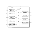
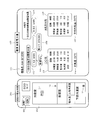
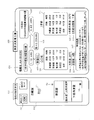
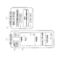
- the figure which shows typically the system containing the power consumption output device which concerns on one Embodiment The figure which shows the structural example of the refrigerator which is household appliances typically The figure which shows the structural example of a power consumption output device typically Figure showing an example of the power consumption output screen (Part 1) Figure showing an example of the power consumption output screen (2) Figure showing an example of the power consumption output screen (Part 3) Figure showing an example of the power consumption output screen (Part 4)
- a refrigerator 1 provided as an example of a home appliance is installed in a house 2 and can communicate with an information output device 4 and a portable terminal 5 via an access point 3.
- the information output device 4 is provided as an example of a power consumption output device. Communication between the refrigerator 1 and the access point 3 is performed by a wireless communication system by a communication adapter 18 provided on the top of the refrigerator 1.
- the refrigerator 1 can also communicate with the mobile terminal 5 and the server 7 connected to the external network 6 via the access point 3.
- the information output device 4 is a so-called personal computer, and is connected to the access point 3 by a wired method or a wireless method.
- the mobile terminal 5 may be a high-function mobile phone such as a so-called smartphone, a tablet PC, or the like.
- the mobile terminal 5 exists in the house 2, the mobile terminal 5 is connected to the access point 3 so as to be communicable by a short-range wireless system. .
- the mobile terminal 5 is located outside the house 2, the mobile terminal 5 is communicably connected to the access point 3 via the network 6 by wide area communication. Further, the mobile terminal 5 can be connected to the access point 3 via the network 6 by wide area communication even from inside the house 2.
- the portable terminal 5 can directly communicate with the refrigerator 1 without going through the access point 3 in the house 2.
- the communication method between the portable terminal 5 and the refrigerator 1 or the access point 3 may be a short-range communication method such as a so-called wireless LAN or Bluetooth (Japan: registered trademark).
- the server 7 is configured by a known computer system, stores various types of information such as information for accessing the refrigerator 1, and is configured to be able to distribute these various types of information.
- information for accessing the refrigerator 1 for example, an IP address can be considered.
- the refrigerator 1 includes a plurality of storage rooms such as a refrigerator room, a vegetable room, an ice making room, a freezer room, and the like.
- a control device 10 that controls the overall operation of the refrigerator 1 based on a control program is provided inside the refrigerator 1.
- the control device 10 includes an operation panel 11, an ambient temperature sensor 12, a door opening sensor 13, a refrigeration cooling mechanism 14, a refrigeration cooling mechanism 15, a defrosting device 16, an ice making device 17, a communication adapter 18, and a storage capacity detection device. 19 etc. are connected.
- the control device 10 controls the entire operation of the refrigerator 1 according to various operation signals input from the operation panel 11 in response to an operation by the user. Moreover, the control apparatus 10 detects the ambient temperature of the refrigerator 1 with the ambient temperature sensor 12 which is an example of an ambient temperature detection means. In addition, the control device 10 detects the open / closed state of the door by an open sensor 13 that is turned on / off in response to opening / closing of a door of a storage room such as a refrigerator room, a vegetable room, an ice making room, a freezer room, and the like. In this case, the control device 10 can detect the number of times the door is opened / closed according to the number of times the door opening sensor 13 is switched on / off. In addition, by counting the time when the door opening sensor 13 is on or off with a timer (not shown), it is possible to detect the time when the door is open or closed.
- a timer not shown
- the refrigeration cooling mechanism 14 includes a well-known refrigeration cycle including a refrigeration cooler (not shown), and cools the storage room set in the refrigeration temperature zone in accordance with a drive signal input from the control device 10. Supply.
- the refrigeration cooling mechanism 15 includes a well-known refrigeration cycle including a refrigeration cooler (not shown), and cools the storage room set in the refrigeration temperature zone in accordance with a drive signal input from the control device 10. Supply.
- the accommodation amount detection device 19 is an example of the accommodation amount detection means, and detects the accommodation amount of foods contained in the storage.
- the accommodation amount detection device 19 is configured to include a known optical sensor installed in the warehouse. And when the illuminance in the warehouse detected by this optical sensor is high, the accommodation amount detection device 19 determines that the amount of accommodation in the warehouse is small, and when the detected illuminance is low, It is determined that the capacity is large.
- the storage amount detection device 19 sets the storage amount of the foods stored in the storage to, for example, 10 levels, that is, 10% to 100% according to the illuminance in the storage detected by the optical sensor. It is set to judge by level.
- the refrigerator 1 can set installation position information for specifying the installation position.
- the control apparatus 10 memorize
- This installation position information can be set, for example, by inputting an address, set by inputting coordinate information such as latitude / longitude, or set by inputting an area name. .
- the defrosting device 16 is for melting and removing frost generated in the coolers of the refrigeration cooling mechanism 14 and the refrigeration cooling mechanism 15, and includes a heater that generates heat when energized.
- the ice making device 17 supplies water to an ice making tray (not shown).
- the ice making device 17 indirectly detects the temperature of the water by detecting the temperature of the ice tray.
- the ice making device 17 operates the refrigeration cycle in the ice making mode until it is determined that the water is frozen, and when it is determined that the water is frozen, the ice making tray is rotated to store the ice in the ice storage container.
- the operation of the refrigeration cycle is for ice making, and a water supply motor (not shown) is driven, so that the power consumption is increased as compared with the normal operation.
- the communication adapter 18 can communicate with the information output device 4 and the portable terminal 5 in the house 2 via the access point 3.
- the communication adapter 18 can communicate with the mobile terminal 5 and the server 7 outside the house 2 via the access point 3 and the Internet 6.
- the control device 10 can transmit various information related to the refrigerator 1 to an external device such as the information output device 4 or the server 7 via the communication adapter 18.
- Examples of information provided from the refrigerator 1 to the information output device 4 include power consumption information indicating the power consumption of the refrigerator 1, model information for specifying the model of the refrigerator 1, operation state information indicating the operation state of the refrigerator 1, refrigerator 1 is setting content information indicating the current setting content, installation position information described above, and the like.
- operating state information for example, defrost history information indicating the presence or absence of a defrosting operation of the cooler by the defrosting device 16, door opening / closing frequency information indicating the number of door opening / closing times, door opening / closing time information indicating door opening / closing time, Various information regarding the operating state of the refrigerator 1 such as ambient temperature information indicating the ambient temperature of the refrigerator 1 and storage capacity information indicating the storage capacity in the warehouse detected by the storage capacity detection device 19 can be considered.
- the information output device 4 includes a control device 30 that controls the overall operation of the information output device 4 based on a control program.
- An operation input unit 31, a display output unit 32, a communication adapter 33, and the like are connected to the control device 30.
- the operation input unit 31 includes, for example, a touch panel switch provided on the screen of the display output unit 32, a mechanical operation switch provided around the display output unit 32, and the like.
- the display output unit 32 is configured by a display panel made of liquid crystal, for example.
- the communication adapter 33 can communicate with the refrigerator 1 and the portable terminal 5 in the house 2 via the access point 3.
- the communication adapter 33 can communicate with the portable terminal 5 and the server 7 outside the house 2 via the access point 3 and the Internet 6.
- control device 30 executes a control program in the CPU, whereby a power consumption information acquisition processing unit 41, a power consumption output processing unit 42, a standard value setting processing unit 43, an outside air temperature detection processing unit 44, a standard value correction process.
- the unit 45, the operation state information acquisition processing unit 46, and the analysis processing unit 47 are virtually realized by software.
- the processing units 41 to 47 may be realized by hardware as an integrated circuit, for example.
- the power consumption information acquisition processing unit 41 is an example of a power consumption information acquisition unit, and acquires power consumption information indicating the current power consumption of the refrigerator 1 from the refrigerator 1 through the communication adapter 33 as needed. And the control apparatus 30 memorize
- the power consumption information acquisition processing unit 41 can also acquire and accumulate power consumption information of the refrigerator from refrigerators other than the refrigerator 1 (not shown).
- the power consumption output processing unit 42 is an example of an output unit, and displays the power consumption of the refrigerator 1 on the display output unit 32 together with a reference value based on the power consumption information acquired by the power consumption information acquisition processing unit 41.
- the power consumption output processing unit 42 integrates the power consumption indicated by the power consumption information acquired from time to time by the power consumption information acquisition processing unit 41 within the second predetermined period from the present, and calculates the accumulated power consumption as a reference value. At the same time, it can be displayed on the display output unit 32. That is, the power consumption output processing unit 42 can display the integrated value of the power consumed by the refrigerator 1 within the second predetermined period from the present.
- the second predetermined period can be appropriately changed and set, but basically, a period shorter than the first predetermined period is set.
- the power consumption output processing unit 42 is set to be able to display the accumulated power consumption of the refrigerator 1 within the past one day, that is, within 24 hours from the present.
- the power consumption output processing unit 42 integrates the power consumption indicated by the power consumption information acquired at any time by the power consumption information acquisition processing unit 41 on the previous day, and displays the accumulated power consumption together with the reference value on the display output unit 32. It is possible. That is, the power consumption output processing unit 42 can display the integrated value of the power consumed by the refrigerator 1 on the previous day. In this case, the power consumption output processing unit 42 is set to be able to display the accumulated power consumption of the refrigerator 1 within the past one day, that is, within 24 hours from the present. In this case, the power consumption output processing unit 42 is set to display the integrated power consumption of the refrigerator 1 from 0:00 to 24:00 on the previous day on the calendar.
- the standard value setting processing unit 43 is an example of standard value setting means, and sets a standard value to be displayed on the display output unit 32 together with the power consumption of the refrigerator 1, in this case, the integrated power consumption.
- Various methods can be adopted as a method for setting the reference value.
- the reference value setting processing unit 43 sets the plurality of refrigerators based on the plurality of power consumption information. It is possible to calculate an average value of power consumption and set the average value as a guide value.
- the reference value setting processing unit 43 specifies the model of each refrigerator based on the model information, and for each of a plurality of refrigerators that are the same model It is possible to calculate an average value.
- the reference value setting processing unit 43 may be set to calculate an average value of only a plurality of refrigerator groups that are the same model as the refrigerator 1.
- the reference value setting processing unit 43 specifies a refrigerator that exists in a predetermined area based on the installation position information. It is possible to calculate an average value for each of a plurality of refrigerators existing in the predetermined area. At this time, the reference value setting processing unit 43 may be set to calculate an average value of only a plurality of refrigerator groups existing in the same area as the refrigerator 1.
- the reference value setting processing unit 43 can set the power consumption indicated by the power consumption information acquired by the power consumption information acquisition processing unit 41 before the first predetermined period as a reference value.
- the outside air temperature detection processing unit 44 is an example of an outside air temperature detecting unit, and detects the temperature of the outside air by a temperature sensor (not shown) included in the information output device 4. Then, the outside temperature detection processing unit 44 outputs outside temperature information indicating the detected temperature to the control device 30.
- the “outside air temperature” here is the temperature outside the information output device 4, and may be the temperature inside the house 2 as long as it is outside the information output device 4. May be the temperature. That is, the temperature at various points outside the information output device 4 can be detected as the outside air temperature by appropriately changing the installation position of the temperature sensor (not shown) inside or outside the house 2.
- the reference value correction processing unit 45 is an example of a reference value correction unit, and appropriately corrects the reference value set by the reference value setting processing unit 43 based on the outside air temperature detected by the outside air temperature detection processing unit 44. That is, the reference value correction processing unit 45 corrects the reference value to a value higher by a predetermined amount when the temperature of the outside air is higher than the predetermined value. The reference value correction processing unit 45 corrects the reference value to a value lower by a predetermined amount when the temperature of the outside air is lower than the predetermined value. It should be noted that the predetermined value and the predetermined amount in the correction process can be appropriately changed and set.
- the operation state information acquisition processing unit 46 is an example of an operation state information acquisition unit, and acquires operation state information indicating the operation state of the refrigerator 1 via the communication adapter 33.
- the power consumption output processing unit 42 displays the driving state indicated by the driving state information on the display output unit 32 together with the power consumption and the reference value. Is possible.
- the operation state information acquisition processing unit 46 can acquire operation state information indicating the operation state of the refrigerator from refrigerators other than the refrigerator 1.
- the analysis processing unit 47 is an example of an analysis unit, and when the power consumption output by the power consumption output processing unit 42 is changed, the cause of the change is analyzed. That is, the analysis processing unit 47, when the power consumption output by the power consumption output processing unit 42 is changed in a mode different from the mode normally assumed, for example, when the power consumption rapidly increases in a short time, When the power consumption is significantly higher than the power consumption in the same period of the previous year, the cause of the change is analyzed based on the operating state information obtained from the refrigerator 1. Specifically, for example, when the current power consumption is higher than the power consumption in the same period of the previous year by a predetermined amount or more, for example, 0.2 kWh higher, the analysis processing unit 47 is based on the operation state information obtained from the refrigerator 1.
- the analysis processing unit 47 specifies, for example, that the amount of storage in the storage is larger than normal and that the number of times of opening and closing the door is higher than normal, for example, “Since the storage is large, It is difficult to cool. Let's organize the inside of the warehouse. Also, be careful about the number of times the door is opened and closed. "
- the information output device 4 is configured to be able to output the power consumption of the refrigerator 1, which is a home appliance, together with a reference value.
- FIG. 4 shows an example of a power consumption output screen for power consumption.
- On this power consumption output screen there are a power consumption amount display unit 100 for displaying the current power consumption amount and a reference value of the refrigerator 1 and a setting state display unit 200 for displaying the current setting contents of the refrigerator 1. Is provided.
- the power consumption display unit 100 displays various information related to the refrigerator 1 based on various information such as power consumption information and operation state information obtained from the refrigerator 1. That is, for example, as shown in FIG. 4, the power consumption display unit 100 includes a model name block 101 that displays the model name of the refrigerator 1, a power consumption block 102 that displays the power consumption of the refrigerator 1, An operation state block 103 for displaying the operation state and an outside air temperature block 104 for displaying the outside air temperature of the refrigerator 1 are provided.
- the power consumption block 102 displays the accumulated power consumption of the refrigerator 1 within the past day, that is, within 24 hours from the present time, that is, the accumulated power consumption of the refrigerator 1 for the past day. Further, “kWh” is set as a unit of power consumption displayed in the power consumption block 102.
- the average power consumption block 105 in which the average power consumption of a plurality of refrigerator groups existing in the same area A as the refrigerator 1 is displayed as a reference value on the power consumption display section 100, and the same area A as the refrigerator 1
- An average operation state block 106 in which an average operation state of a plurality of refrigerator groups existing in the interior is displayed, and an average outside air in which an average outside temperature of the plurality of refrigerator groups existing in the same area A as the refrigerator 1 is displayed.
- a temperature block 107 is provided.
- the average power consumption block 105 includes the accumulated power consumption of the plurality of refrigerator groups in the area A, that is, the plurality of refrigerator groups including the refrigerator 1, within the past one day, that is, within 24 hours from the present, that is, for the past one day.
- the integrated power consumption of the plurality of refrigerator groups in the area A is displayed as a guide value. Further, “kWh” is set as a unit of power consumption displayed in the average power consumption block 105.
- the power consumption display unit 100 displays the difference between the power consumption of the refrigerator 1 displayed on the power consumption block 102 and the average power consumption displayed on the average power consumption block 105, that is, the “reference value”.
- a power consumption difference block 108, a defrosting operation block 109 indicating whether or not the defrosting operation is performed in the refrigerator 1, and the like are provided. Note that “kWh” is set as a unit of power consumption displayed in the power consumption difference block 108.
- the defrosting operation block 109 includes character information such as “with defrosting”. Is displayed.
- character information such as “no defrosting” is displayed in the defrosting operation block 109.
- the setting state display unit 200 schematically displays the current setting state of the refrigerator 1 based on the setting content information obtained from the refrigerator 1. That is, for example, as shown in FIG. 4, the setting state display unit 200 is provided with a power saving block 201, a refrigerator block 202, and the like.
- the power saving block 201 displays whether or not the refrigerator 1 is set in the power saving mode. When the power saving mode is set in the refrigerator 1, character information such as “ON” is displayed on the power saving block 201. On the other hand, when the power saving mode is not set in the refrigerator 1, character information such as “OFF” is displayed on the power saving block 201.
- the refrigerator block 202 displays the cooling level set for each storage room included in the refrigerator 1 and whether or not the settings related to each storage room are locked. For example, in the state shown in FIG. 4, the symbol S1 indicating that the cooling level of the refrigerator compartment is set to the medium level, the symbol S2 indicating that the cooling level of the lower freezer compartment is set to the weak level, and the refrigerator compartment. A symbol S3 or the like indicating that the setting relating to the lock is locked is displayed.
- the power consumption display unit 100 displays the past power consumption in which the power consumption of the refrigerator 1 before the predetermined period is displayed as a reference value.
- Block 110 is provided.
- the past power consumption block 110 displays the power consumption of the refrigerator 1 in “kWh” units one year before the present, that is, the same period of last year.
- the power consumption display unit 100 is provided with a past operation state block 111 that displays the operation state of the refrigerator 1 before a predetermined period from the present time, instead of the average operation state block 106 described above.
- the past operation state block 111 displays the operation state of the refrigerator 1 one year before the present, that is, the same period of last year.
- the power consumption display unit 100 is provided with a past outside air temperature block 112 for displaying the outside air temperature of the refrigerator 1 before a predetermined period from the present time, instead of the average outside air temperature block 107 described above.
- the past outside air temperature block 112 displays the outside air temperature of the refrigerator 1 one year before the present, that is, the same period of last year.
- the power consumption display unit 100 is provided with a storage capacity display block 113 for displaying the current storage capacity of the refrigerator 1.
- the power consumption amount display unit 100 is provided with a past storage amount block 114 that displays the storage amount of the refrigerator 1 before a predetermined period from the present time. In this case, the past capacity block 114 displays the capacity of the refrigerator 1 one year before the present, that is, the same period of last year.
- the power consumption display unit 100 is further provided with an analysis result block 115.
- advice such as a cause of a change in power consumption and a coping method thereof is displayed based on message data generated according to the analysis result by the analysis processing unit 47.
- the power consumption display unit 100 is provided with the model name block 101, the power consumption block 102, and the average power consumption block 105 described above.
- the display example shown in FIG. 7 is a display example that simply shows the current power consumption and the reference value of the refrigerator 1.
- the content of the power consumption output screen by the information output apparatus 4 can be changed and implemented suitably.
- the power consumption output screen displayed by the information output device 4 can be switched according to, for example, an operation input by the user via the operation input unit 31.
- the power consumption information indicating the current power consumption of the refrigerator 1 is acquired as needed from the refrigerator 1 that is a home appliance, and the refrigerator 1 is based on the acquired power consumption information.
- the power consumption is output together with the reference value.
- the power consumption indicated by the power consumption information acquired from the refrigerator 1 at any time within the past predetermined period from the present is integrated, and the integrated power consumption is output together with the reference value. Therefore, it can be easily recognized whether the current power consumption of the refrigerator 1 is appropriate or not by comparing with the accumulated power consumption of the refrigerator 1 within the past predetermined period.
- the power consumption indicated by the power consumption information acquired from the refrigerator 1 on the previous day is integrated, and the integrated power consumption is output together with the reference value. Therefore, it can be easily recognized whether the current power consumption of the refrigerator 1 is appropriate or not by comparison with the integrated power consumption of the refrigerator 1 on the previous day.
- the average value of the power consumption of the plurality of refrigerator groups is set as a guide value based on the plurality of power consumption information. To do. Thereby, it is possible to easily recognize whether or not the integrated power consumption of the refrigerator 1 is appropriate by comparing with the average power consumption, and it is possible to make a determination based on the average level of power consumption. Become.
- the power consumption output device 4 when power consumption information is acquired from a plurality of refrigerators, an average value is calculated for each of a plurality of refrigerator groups of the same model. Thereby, whether the integrated power consumption of the refrigerator 1 is appropriate can be easily recognized by comparing the power consumption of the refrigerator 1 and the refrigerator group of the same model, and a determination based on a refrigerator having the same performance Is possible.
- an average value is calculated for each of a plurality of home appliances existing in the same predetermined area as the refrigerator 1.
- the integrated power consumption of the refrigerator 1 is appropriate by comparing with the power consumption of the refrigerator existing in an area where the environmental conditions such as temperature and humidity are substantially the same. It is possible to make a judgment based on a refrigerator having the same environmental conditions.
- the power consumption indicated by the power consumption information acquired from the refrigerator 1 before a predetermined period, for example, one year ago is set as a reference value.
- the integrated power consumption of the refrigerator 1 is appropriate, for example, by comparing with the power consumption of the refrigerator 1 in the same period of last year, and the power consumption under similar climatic conditions. Judgment on the basis of can be made.
- the operation state of the refrigerator 1 is output together with the power consumption and the reference value based on the operation state information acquired from the refrigerator 1. Thereby, it can be recognized whether the integrated power consumption of the refrigerator 1 is appropriate, also considering the operating state of the refrigerator 1.
- the operating state of the refrigerator 1 includes, for example, the presence or absence of a defrosting operation of the cooler, the number of times the door is opened and closed, the door opening and closing time, the temperature around the refrigerator 1, and the amount of food stored in the cabinet.
- Various operation states related to the refrigerator are conceivable.
- “kWh” is set as a display unit of power consumption.
- the power consumption output device 4 when the power consumption to be displayed changes, the cause of the change is analyzed and the analysis result is also displayed. Thereby, the user can easily recognize the cause of the change in the power consumption, and can easily cope with the cause.
- the information output device 4 includes an audio output device including, for example, a speaker.
- the information output device 4 may be configured to output the power consumption amount and the reference value by sound instead of the output by the display described above or in combination with the output by the display. Good.
- the information output device 4 may be configured to indicate the power consumption amount and the reference value at a plurality of levels according to the number of symbol marks such as a star mark and a light bulb mark. Further, the information output device 4 may be configured to show the power consumption amount and the reference value in terms of electricity bills.
- the refrigerator may include a deodorizing device that deodorizes the room by applying a high voltage, an electrostatic atomizer that generates water vapor in a vegetable room, and the like.
- a deodorizing device that deodorizes the room by applying a high voltage
- an electrostatic atomizer that generates water vapor in a vegetable room, and the like.
- household appliances it is not restricted to a refrigerator, For example, various household appliances, such as a washing machine and a heating cooker, are contained.
- the power consumption output device includes power consumption information acquisition means and output means.
- the power consumption information acquisition unit acquires power consumption information indicating the power consumption of the home appliance.
- the output means outputs the power consumption of the home appliance together with the reference value based on the power consumption information acquired by the power consumption information acquisition means.
Landscapes
- Engineering & Computer Science (AREA)
- Power Engineering (AREA)
- Physics & Mathematics (AREA)
- General Physics & Mathematics (AREA)
- General Engineering & Computer Science (AREA)
- Automation & Control Theory (AREA)
- Chemical & Material Sciences (AREA)
- Combustion & Propulsion (AREA)
- Mechanical Engineering (AREA)
- Thermal Sciences (AREA)
- Radar, Positioning & Navigation (AREA)
- Electromagnetism (AREA)
- Cold Air Circulating Systems And Constructional Details In Refrigerators (AREA)
- Devices That Are Associated With Refrigeration Equipment (AREA)
- User Interface Of Digital Computer (AREA)
- Theoretical Computer Science (AREA)
Abstract
Description
外気温度検出処理部44は、外気温度検出手段の一例であり、情報出力装置4が備える図示しない温度センサにより外気の温度を検出する。そして、外気温度検出処理部44は、検出した温度を示す外気温度情報を制御装置30に出力する。なお、ここでいう「外気の温度」とは、情報出力装置4の外部の温度のことであり、情報出力装置4の外部であれば住宅2内の温度であってもよいし、住宅2外の温度であってもよい。即ち、図示しない温度センサの設置位置を住宅2内あるいは住宅2外で適宜変更することにより、情報出力装置4の外部における様々なポイントの温度を外気温度として検出することができる。
例えば図4には、消費電力の消費電力出力画面の一例を示している。この消費電力出力画面には、冷蔵庫1の現在の消費電力量および目安値などを表示するための消費電力量表示部100および冷蔵庫1の現在の設定内容を表示するための設定状態表示部200が設けられている。
また、消費電力出力装置4によれば、冷蔵庫1から取得した運転状態情報に基づいて当該冷蔵庫1の運転状態も消費電力および目安値とともに出力する。これにより、冷蔵庫1の積算消費電力が適当であるのか否かを、当該冷蔵庫1の運転状態も考慮しながら認識することができる。なお、冷蔵庫1の運転状態としては、例えば、冷却器の除霜運転の有無、扉の開閉回数、扉の開閉時間、冷蔵庫1の周囲の温度、庫内に収容されている食品類の収容量など、冷蔵庫に関する種々の運転状態が考えられる。
情報出力装置4は、例えばスピーカなどからなる音声出力装置を備え、上記した表示による出力に代えて、あるいは、表示による出力と併用して、消費電力量や目安値を音声により出力する構成としてもよい。
Claims (16)
- 家電機器の消費電力を示す消費電力情報を取得する消費電力情報取得手段と、
前記消費電力情報取得手段が取得した前記消費電力情報に基づいて前記家電機器の消費電力を目安値とともに出力する出力手段と、
を備える消費電力出力装置。 - 前記出力手段は、現在から過去所定期間内において前記消費電力情報取得手段が取得した前記消費電力情報が示す消費電力を積算し、その積算消費電力を前記目安値とともに出力する請求項1に記載の消費電力出力装置。
- 前記出力手段は、前日において前記消費電力情報取得手段が取得した前記消費電力情報が示す消費電力を積算し、その積算消費電力を前記目安値とともに出力する請求項1に記載の消費電力出力装置。
- 前記目安値を設定する目安値設定手段をさらに備え、
前記消費電力情報取得手段は、複数の前記家電機器から前記消費電力情報を取得し、
前記目安値設定手段は、前記消費電力情報取得手段が取得した複数の前記消費電力情報に基づいて、複数の前記家電機器の消費電力の平均値を前記目安値として設定する請求項1から3の何れか1項に記載の消費電力出力装置。 - 前記目安値設定手段は、同機種である複数の前記家電機器ごとに前記平均値を算出する請求項4に記載の消費電力出力装置。
- 前記目安値設定手段は、所定地域内に存在する複数の前記家電機器ごとに前記平均値を算出する請求項4に記載の消費電力出力装置。
- 前記目安値を設定する目安値設定手段をさらに備え、
前記目安値設定手段は、前記消費電力情報取得手段が所定期間前に取得した前記消費電力情報が示す消費電力を前記目安値として設定する請求項1から3の何れか1項に記載の消費電力出力装置。 - 外気の温度を検出する外気温度検出手段と、
前記目安値設定手段が設定した前記目安値を、前記外気温度検出手段が検出する外気の温度に基づいて補正する目安値補正手段と、
をさらに備える請求項4から7の何れか1項に記載の消費電力出力装置。 - 前記家電機器の運転状態を示す運転状態情報を取得する運転状態情報取得手段をさらに備え、
前記出力手段は、前記運転状態情報取得手段が取得した前記運転状態情報に基づいて前記家電機器の運転状態も前記消費電力および前記目安値とともに出力する請求項1から8の何れか1項に記載の消費電力出力装置。 - 前記家電機器は冷蔵庫であり、
前記運転状態情報取得手段は、前記冷蔵庫が備える冷却器の除霜運転の有無を示す除霜履歴情報を前記運転状態情報として取得する請求項9に記載の消費電力出力装置。 - 前記家電機器は冷蔵庫であり、
前記運転状態情報取得手段は、前記冷蔵庫が備える扉の開閉回数を示す扉開閉回数情報を前記運転状態情報として取得する請求項9に記載の消費電力出力装置。 - 前記家電機器は冷蔵庫であり、
前記運転状態情報取得手段は、前記冷蔵庫が備える扉の開閉時間を示す扉開閉時間情報を前記運転状態情報として取得する請求項9に記載の消費電力出力装置。 - 前記家電機器は冷蔵庫であり、
前記冷蔵庫は、当該冷蔵庫の周囲の温度を検出する周囲温度検出手段を備え、
前記運転状態情報取得手段は、前記周囲温度検出手段が検出する前記冷蔵庫の周囲の温度を示す周囲温度情報を前記運転状態情報として取得する請求項9に記載の消費電力出力装置。 - 前記家電機器は冷蔵庫であり、
前記冷蔵庫は、庫内に収容されている食品類の収容量を検出する収容量検出手段を備え、
前記運転状態情報取得手段は、前記収容量検出手段が検出する前記冷蔵庫の庫内の収容量を示す収容量情報を前記運転状態情報として取得する請求項9に記載の消費電力出力装置。 - 前記出力手段によって表示される前記消費電力の単位として「kWh」が設定されている請求項1から14の何れか1項に記載の消費電力出力装置。
- 前記出力手段が出力する前記消費電力が変化した場合に、その変化の原因を解析する解析手段をさらに備える請求項1から15の何れか1項に記載の消費電力出力装置。
Priority Applications (4)
| Application Number | Priority Date | Filing Date | Title |
|---|---|---|---|
| EP14839818.3A EP3040658B1 (en) | 2013-08-26 | 2014-07-07 | Home appliance with a power-consumption output device |
| CN201480047757.4A CN105492844B (zh) | 2013-08-26 | 2014-07-07 | 耗电输出装置 |
| KR1020167004650A KR20160035016A (ko) | 2013-08-26 | 2014-07-07 | 소비전력 출력장치 |
| US15/053,520 US10126047B2 (en) | 2013-08-26 | 2016-02-25 | Power-consumption output device |
Applications Claiming Priority (2)
| Application Number | Priority Date | Filing Date | Title |
|---|---|---|---|
| JP2013-174493 | 2013-08-26 | ||
| JP2013174493A JP6430106B2 (ja) | 2013-08-26 | 2013-08-26 | 消費電力出力装置 |
Related Child Applications (1)
| Application Number | Title | Priority Date | Filing Date |
|---|---|---|---|
| US15/053,520 Continuation US10126047B2 (en) | 2013-08-26 | 2016-02-25 | Power-consumption output device |
Publications (1)
| Publication Number | Publication Date |
|---|---|
| WO2015029600A1 true WO2015029600A1 (ja) | 2015-03-05 |
Family
ID=52586177
Family Applications (1)
| Application Number | Title | Priority Date | Filing Date |
|---|---|---|---|
| PCT/JP2014/068052 Ceased WO2015029600A1 (ja) | 2013-08-26 | 2014-07-07 | 消費電力出力装置 |
Country Status (7)
| Country | Link |
|---|---|
| US (1) | US10126047B2 (ja) |
| EP (1) | EP3040658B1 (ja) |
| JP (1) | JP6430106B2 (ja) |
| KR (1) | KR20160035016A (ja) |
| CN (1) | CN105492844B (ja) |
| TW (1) | TWI639081B (ja) |
| WO (1) | WO2015029600A1 (ja) |
Cited By (1)
| Publication number | Priority date | Publication date | Assignee | Title |
|---|---|---|---|---|
| JP2023073773A (ja) * | 2021-11-16 | 2023-05-26 | 東芝ライフスタイル株式会社 | プログラムおよび冷蔵庫 |
Families Citing this family (8)
| Publication number | Priority date | Publication date | Assignee | Title |
|---|---|---|---|---|
| CN105408898B (zh) | 2013-03-15 | 2019-05-28 | 弗兰克公司 | 测量数据的自动记录和图形生成 |
| JP6080655B2 (ja) * | 2013-04-03 | 2017-02-15 | 三菱電機株式会社 | 冷蔵庫 |
| SG10201805510YA (en) | 2018-06-26 | 2020-01-30 | Luxon Data Holdings Pte Ltd | Monitoring device and system |
| JP2020046093A (ja) * | 2018-09-18 | 2020-03-26 | パナソニックIpマネジメント株式会社 | 冷蔵庫、システム |
| WO2022102633A1 (ja) * | 2020-11-16 | 2022-05-19 | シャープ株式会社 | 状態通知装置、プログラム、及び、状態通知方法 |
| US11936489B2 (en) * | 2021-02-02 | 2024-03-19 | True Manufacturing Co., Inc. | Systems, methods, and appliances that enable regional control of refrigeration appliances |
| CN114739090B (zh) * | 2022-04-13 | 2024-06-18 | 海信冰箱有限公司 | 一种冰箱及其耗电量监测方法 |
| KR20250056038A (ko) * | 2023-10-18 | 2025-04-25 | 삼성전자주식회사 | 검사 장치 및 그 제어 방법 |
Citations (10)
| Publication number | Priority date | Publication date | Assignee | Title |
|---|---|---|---|---|
| JPH10123185A (ja) * | 1996-10-22 | 1998-05-15 | Kajima Corp | 電力消費量モニター |
| JPH11337252A (ja) * | 1998-05-21 | 1999-12-10 | Matsushita Electric Ind Co Ltd | 冷蔵庫の使い方比較システム |
| US20060123807A1 (en) * | 2004-12-14 | 2006-06-15 | Sullivan C B | Apparatus and method for monitoring and displaying power usage |
| JP2006190145A (ja) * | 2005-01-07 | 2006-07-20 | Omron Corp | 店舗管理システム、店舗制御装置および店舗制御方法、管理サーバおよび管理方法、並びにプログラム |
| JP2007014179A (ja) * | 2004-08-12 | 2007-01-18 | Sanyo Electric Co Ltd | デマンド制御装置および消費電力予測方法ならびにプログラム |
| JP2009020721A (ja) * | 2007-07-12 | 2009-01-29 | Daikin Ind Ltd | 空調機の劣化判定装置、空調システム、劣化判定方法および劣化判定プログラム |
| JP2010014323A (ja) * | 2008-07-03 | 2010-01-21 | Hitachi Ltd | 冷熱供給システムの劣化診断装置、劣化診断方法、及び劣化診断システム |
| JP2012052793A (ja) * | 2009-03-27 | 2012-03-15 | Mitsubishi Electric Corp | 空気調和機 |
| JP2012133764A (ja) | 2010-12-02 | 2012-07-12 | Sharp Corp | コントローラ、ネットワークシステム、および情報処理方法 |
| US20120176252A1 (en) * | 2011-01-12 | 2012-07-12 | Emerson Electric Co. | Apparatus and Method for Determining Load of Energy Consuming Appliances Within a Premises |
Family Cites Families (27)
| Publication number | Priority date | Publication date | Assignee | Title |
|---|---|---|---|---|
| JP4682414B2 (ja) * | 2000-11-06 | 2011-05-11 | パナソニック株式会社 | 収納庫 |
| US6668240B2 (en) * | 2001-05-03 | 2003-12-23 | Emerson Retail Services Inc. | Food quality and safety model for refrigerated food |
| US7617690B2 (en) * | 2004-11-02 | 2009-11-17 | Helmer, Inc. | Blood products freezer with event log |
| CN101345420B (zh) * | 2005-06-01 | 2011-03-02 | 三洋电机株式会社 | 请求控制装置以及消耗功率预测方法与程序 |
| JP2007060848A (ja) * | 2005-08-26 | 2007-03-08 | Sanyo Electric Co Ltd | 電力量制御装置および電力量制御方法ならびにプログラム |
| US7409258B2 (en) * | 2006-04-28 | 2008-08-05 | Taiwan Semiconductor Manufacturing Company, Ltd. | Method and system for measuring customer delivery service |
| US7693670B2 (en) | 2007-08-14 | 2010-04-06 | General Electric Company | Cognitive electric power meter |
| US8627689B2 (en) | 2008-09-15 | 2014-01-14 | General Electric Company | Energy management of clothes washer appliance |
| TWI419431B (zh) | 2008-11-06 | 2013-12-11 | 財團法人工業技術研究院 | 電能管理插座架構 |
| TWI513947B (zh) | 2008-12-24 | 2015-12-21 | Panasonic Corp | Refrigerators and compressors |
| TWM360365U (en) | 2009-01-23 | 2009-07-01 | Josephtec Co Ltd | Electric power meter and its corresponding display device with varieties of input and output wire sleeve configuration |
| SG179140A1 (en) | 2009-09-09 | 2012-04-27 | Panasonic Corp | Power control system |
| KR101595391B1 (ko) * | 2009-10-26 | 2016-02-18 | 엘지전자 주식회사 | 세탁기 제어 장치 및 제어 방법 |
| CN102893107B (zh) | 2010-01-14 | 2015-02-25 | 松下电器产业株式会社 | 冷藏库 |
| KR101637354B1 (ko) * | 2010-01-20 | 2016-07-07 | 엘지전자 주식회사 | 냉장고 및 그 제어방법 |
| US9353990B2 (en) * | 2010-02-23 | 2016-05-31 | Lg Electronics Inc. | Refrigerator including a terminal, and method for controlling same |
| DE102010030830A1 (de) * | 2010-07-01 | 2012-01-05 | Robert Bosch Gmbh | Verfahren zum Betreiben einer Temperaturbegrenzungseinrichtung, Temperaturbegrenzungseinrichtung sowie elektrisches Gerät |
| TWI423549B (zh) * | 2010-07-02 | 2014-01-11 | Univ Nat Chiao Tung | 辨識電器狀態的電力監測裝置及其電力監測方法 |
| EP2469328A1 (en) | 2010-12-22 | 2012-06-27 | Chimei InnoLux Corporation | Method for fabricating a touch panel |
| KR101779428B1 (ko) * | 2010-12-24 | 2017-09-18 | 엘지전자 주식회사 | 전력 제어 장치 및 전력 제어 방법 |
| EP2662651B1 (en) * | 2011-01-06 | 2020-04-15 | LG Electronics Inc. | Refrigerator comprising a display |
| USD672666S1 (en) | 2011-01-12 | 2012-12-18 | Emerson Electric Co. | Thermostat |
| TWM408027U (en) | 2011-01-18 | 2011-07-21 | Univ Far East | intelligent refrigerator |
| JP5085751B2 (ja) * | 2011-02-28 | 2012-11-28 | 株式会社東芝 | 電子機器及び情報出力方法 |
| TW201322579A (zh) | 2011-11-25 | 2013-06-01 | Chunghwa Telecom Co Ltd | 雲端用電監控系統及其方法 |
| JPWO2013088584A1 (ja) * | 2011-12-14 | 2015-04-27 | 京セラ株式会社 | 表示端末、電力制御システム、および表示方法 |
| JP4962813B1 (ja) | 2012-01-23 | 2012-06-27 | 日本テクノ株式会社 | アラーム出力装置、アラーム出力方法 |
-
2013
- 2013-08-26 JP JP2013174493A patent/JP6430106B2/ja not_active Expired - Fee Related
-
2014
- 2014-07-07 EP EP14839818.3A patent/EP3040658B1/en not_active Not-in-force
- 2014-07-07 WO PCT/JP2014/068052 patent/WO2015029600A1/ja not_active Ceased
- 2014-07-07 KR KR1020167004650A patent/KR20160035016A/ko not_active Ceased
- 2014-07-07 CN CN201480047757.4A patent/CN105492844B/zh not_active Expired - Fee Related
- 2014-07-18 TW TW103124652A patent/TWI639081B/zh not_active IP Right Cessation
-
2016
- 2016-02-25 US US15/053,520 patent/US10126047B2/en not_active Expired - Fee Related
Patent Citations (10)
| Publication number | Priority date | Publication date | Assignee | Title |
|---|---|---|---|---|
| JPH10123185A (ja) * | 1996-10-22 | 1998-05-15 | Kajima Corp | 電力消費量モニター |
| JPH11337252A (ja) * | 1998-05-21 | 1999-12-10 | Matsushita Electric Ind Co Ltd | 冷蔵庫の使い方比較システム |
| JP2007014179A (ja) * | 2004-08-12 | 2007-01-18 | Sanyo Electric Co Ltd | デマンド制御装置および消費電力予測方法ならびにプログラム |
| US20060123807A1 (en) * | 2004-12-14 | 2006-06-15 | Sullivan C B | Apparatus and method for monitoring and displaying power usage |
| JP2006190145A (ja) * | 2005-01-07 | 2006-07-20 | Omron Corp | 店舗管理システム、店舗制御装置および店舗制御方法、管理サーバおよび管理方法、並びにプログラム |
| JP2009020721A (ja) * | 2007-07-12 | 2009-01-29 | Daikin Ind Ltd | 空調機の劣化判定装置、空調システム、劣化判定方法および劣化判定プログラム |
| JP2010014323A (ja) * | 2008-07-03 | 2010-01-21 | Hitachi Ltd | 冷熱供給システムの劣化診断装置、劣化診断方法、及び劣化診断システム |
| JP2012052793A (ja) * | 2009-03-27 | 2012-03-15 | Mitsubishi Electric Corp | 空気調和機 |
| JP2012133764A (ja) | 2010-12-02 | 2012-07-12 | Sharp Corp | コントローラ、ネットワークシステム、および情報処理方法 |
| US20120176252A1 (en) * | 2011-01-12 | 2012-07-12 | Emerson Electric Co. | Apparatus and Method for Determining Load of Energy Consuming Appliances Within a Premises |
Non-Patent Citations (1)
| Title |
|---|
| See also references of EP3040658A4 |
Cited By (2)
| Publication number | Priority date | Publication date | Assignee | Title |
|---|---|---|---|---|
| JP2023073773A (ja) * | 2021-11-16 | 2023-05-26 | 東芝ライフスタイル株式会社 | プログラムおよび冷蔵庫 |
| JP7387694B2 (ja) | 2021-11-16 | 2023-11-28 | 東芝ライフスタイル株式会社 | プログラムおよび冷蔵庫 |
Also Published As
| Publication number | Publication date |
|---|---|
| JP2015042927A (ja) | 2015-03-05 |
| CN105492844A (zh) | 2016-04-13 |
| EP3040658A1 (en) | 2016-07-06 |
| JP6430106B2 (ja) | 2018-11-28 |
| TWI639081B (zh) | 2018-10-21 |
| US10126047B2 (en) | 2018-11-13 |
| TW201516641A (zh) | 2015-05-01 |
| EP3040658B1 (en) | 2020-08-19 |
| KR20160035016A (ko) | 2016-03-30 |
| US20160169577A1 (en) | 2016-06-16 |
| EP3040658A4 (en) | 2017-05-31 |
| CN105492844B (zh) | 2019-05-03 |
Similar Documents
| Publication | Publication Date | Title |
|---|---|---|
| JP6430106B2 (ja) | 消費電力出力装置 | |
| US20190137169A1 (en) | Information terminal device, operating information provision system, and operating information provision program | |
| KR101779728B1 (ko) | 가전기기 및 네트워크 시스템 | |
| JP3990884B2 (ja) | 冷蔵庫の遠隔点検システムおよび冷蔵庫の遠隔点検方法 | |
| JP6080655B2 (ja) | 冷蔵庫 | |
| US20170186079A1 (en) | Refrigerator | |
| KR101982776B1 (ko) | 냉장고 및 그 동작방법 | |
| CN105683689A (zh) | 冰箱、冰箱管理系统以及冰箱控制方法 | |
| JP6905869B2 (ja) | 家電機器システム、家電機器の診断方法、及び端末機器 | |
| JP2010078198A (ja) | 冷却システム | |
| KR20140099594A (ko) | 냉장고 제어 방법 | |
| JP2014081336A (ja) | 機器情報表示システム | |
| CN114636274A (zh) | 家电系统 | |
| KR20160099939A (ko) | 냉장고의 야간모드 제어 시스템 | |
| WO2018116666A1 (ja) | 電子装置、および、電子装置の制御方法 | |
| KR20070088834A (ko) | 공기조화기에서의 화면표시방법 | |
| JP7352348B2 (ja) | 冷蔵庫 | |
| KR20170023465A (ko) | 네트워크를 통해 냉장고의 관리 정보를 제공하기 위한 냉장고 제어 시스템 및 그 방법 | |
| CN114719554A (zh) | 冰箱的控制方法与冰箱 | |
| KR102013452B1 (ko) | 냉장고 제어 방법 | |
| JP2023073773A (ja) | プログラムおよび冷蔵庫 | |
| KR20250027132A (ko) | 냉장고 및 그의 제어 방법 |
Legal Events
| Date | Code | Title | Description |
|---|---|---|---|
| WWE | Wipo information: entry into national phase |
Ref document number: 201480047757.4 Country of ref document: CN |
|
| 121 | Ep: the epo has been informed by wipo that ep was designated in this application |
Ref document number: 14839818 Country of ref document: EP Kind code of ref document: A1 |
|
| ENP | Entry into the national phase |
Ref document number: 20167004650 Country of ref document: KR Kind code of ref document: A |
|
| NENP | Non-entry into the national phase |
Ref country code: DE |
|
| REEP | Request for entry into the european phase |
Ref document number: 2014839818 Country of ref document: EP |
|
| WWE | Wipo information: entry into national phase |
Ref document number: 2014839818 Country of ref document: EP |