WO2015029663A1 - シリンダヘッドボルトの締結構造 - Google Patents
シリンダヘッドボルトの締結構造 Download PDFInfo
- Publication number
- WO2015029663A1 WO2015029663A1 PCT/JP2014/069719 JP2014069719W WO2015029663A1 WO 2015029663 A1 WO2015029663 A1 WO 2015029663A1 JP 2014069719 W JP2014069719 W JP 2014069719W WO 2015029663 A1 WO2015029663 A1 WO 2015029663A1
- Authority
- WO
- WIPO (PCT)
- Prior art keywords
- cylinder head
- head bolt
- bolt
- fastening structure
- flat washer
- Prior art date
- Legal status (The legal status is an assumption and is not a legal conclusion. Google has not performed a legal analysis and makes no representation as to the accuracy of the status listed.)
- Ceased
Links
Images


Classifications
-
- F—MECHANICAL ENGINEERING; LIGHTING; HEATING; WEAPONS; BLASTING
- F02—COMBUSTION ENGINES; HOT-GAS OR COMBUSTION-PRODUCT ENGINE PLANTS
- F02F—CYLINDERS, PISTONS OR CASINGS, FOR COMBUSTION ENGINES; ARRANGEMENTS OF SEALINGS IN COMBUSTION ENGINES
- F02F1/00—Cylinders; Cylinder heads
- F02F1/24—Cylinder heads
-
- F—MECHANICAL ENGINEERING; LIGHTING; HEATING; WEAPONS; BLASTING
- F16—ENGINEERING ELEMENTS AND UNITS; GENERAL MEASURES FOR PRODUCING AND MAINTAINING EFFECTIVE FUNCTIONING OF MACHINES OR INSTALLATIONS; THERMAL INSULATION IN GENERAL
- F16B—DEVICES FOR FASTENING OR SECURING CONSTRUCTIONAL ELEMENTS OR MACHINE PARTS TOGETHER, e.g. NAILS, BOLTS, CIRCLIPS, CLAMPS, CLIPS OR WEDGES; JOINTS OR JOINTING
- F16B31/00—Screwed connections specially modified in view of tensile load; Break-bolts
- F16B31/04—Screwed connections specially modified in view of tensile load; Break-bolts for maintaining a tensile load
-
- F—MECHANICAL ENGINEERING; LIGHTING; HEATING; WEAPONS; BLASTING
- F02—COMBUSTION ENGINES; HOT-GAS OR COMBUSTION-PRODUCT ENGINE PLANTS
- F02F—CYLINDERS, PISTONS OR CASINGS, FOR COMBUSTION ENGINES; ARRANGEMENTS OF SEALINGS IN COMBUSTION ENGINES
- F02F7/00—Casings, e.g. crankcases
- F02F7/0021—Construction
- F02F2007/0041—Fixing Bolts
-
- F—MECHANICAL ENGINEERING; LIGHTING; HEATING; WEAPONS; BLASTING
- F02—COMBUSTION ENGINES; HOT-GAS OR COMBUSTION-PRODUCT ENGINE PLANTS
- F02F—CYLINDERS, PISTONS OR CASINGS, FOR COMBUSTION ENGINES; ARRANGEMENTS OF SEALINGS IN COMBUSTION ENGINES
- F02F7/00—Casings, e.g. crankcases
- F02F7/006—Camshaft or pushrod housings
- F02F2007/0063—Head bolts; Arrangements of cylinder head bolts
Definitions
- the present invention relates to a cylinder head bolt fastening structure for fastening a cylinder head to an engine case by screwing a cylinder head bolt inserted into the cylinder head into either a cylinder or a crankcase constituting the engine case. is there.
- a relatively long cylinder head bolt 8 is attached to the cylinder head 1.
- the cylinder head 1 and the crankcase 4 are connected to each other in an arrangement in which the cylinder 3 is sandwiched therebetween (see Patent Document 1).
- an outer diameter R1 and a male screw 8c (FIG. 1) of the upper end portion provided with the rotation operation portion 8a are provided.
- a tension bolt is used in which the outer diameter R2 of the intermediate cylindrical portion 8b is smaller than the outer diameter of the lower end.
- the cylinder head bolt 8 made of this tension bolt is a shaft that is generated in the axial direction along with the large tension (tension) caused by the restoring force generated in the middle cylindrical portion 8b having a small outer diameter during fastening.
- the cylinder head is fixed to the engine case 2 (FIG. 1) by force.
- a flat washer 9 is interposed under the neck of the cylinder head bolt 8.
- Measuring the axial force of the cylinder head bolt 8 one by one in the assembly process of the engine leads to an increase in working time.
- the tightening torque that can be directly measured with a torque wrench tightening the cylinder head bolt 8 within the specified range, the cylinder head The bolt 8 axis force is managed.
- the axial force tends to be a value deviating from the reference value compared to the case where the sliding surface is constant.
- the variation in the axial force may increase and the cylinder head bolt 8 may be loosened.
- the cylinder head 1 is made of aluminum and the cylinder head bolt 8 and the flat washer 9 are surface-treated with iron, so that the friction surface material and surface roughness are different. This is because the friction coefficient varies depending on the surface state of the friction surface.
- the present invention has been made in view of the above problems, and an object of the present invention is to provide a fastening structure for a cylinder head bolt designed to always obtain a substantially constant axial force after tightening.
- a cylinder head bolt fastening structure is configured such that a cylinder head bolt inserted through a cylinder head is screwed into an engine case including a cylinder and a crankcase, whereby the cylinder head is The structure is fastened to the engine case, and a flat washer is provided between the rotation operation portion provided on the head of the cylinder head bolt and the upper surface of the cylinder head, and a spring force is applied in the axial direction superimposed on the flat washer.
- a spring member that expresses, and a frictional resistance between the rotation operation portion of the cylinder head bolt and the spring member is a frictional resistance between the spring member and the flat washer, and on the flat washer and the cylinder head.
- the respective contact areas are set so as to be smaller than the frictional resistance with the seat surface.
- the frictional resistance means a resistance force at the time of static friction, and is determined by a contact area, a material, a surface roughness, etc., of which the contact area is dominant.
- a disc spring as the spring member.
- the disc spring has a small frictional resistance because it is circular and is in line contact with the seating surface of the cylinder head bolt in a free state before the start of tightening of the cylinder head bolt. Further, since the outer diameter of the disc spring is set larger than the outer diameter of the rotation operation portion when the fastening is completed, the contact area between the rotation operation portion and the disc spring is reduced, and the frictional resistance between the two is reduced. Become. Therefore, slippage is likely to occur between the rotation operation unit and the disc spring. In addition, the disc spring has no pointed parts that may be damaged when it contacts the cylinder head bolt seat and the flat washer, and it will be flat when pressure is applied by tightening the cylinder head bolt. There is an advantage of smooth deformation.
- the cylinder head bolt is a tension bolt in which an intermediate cylindrical portion has an outer diameter smaller than an upper end portion provided with the rotation operation portion and a lower end portion provided with a male screw.
- the tension bolt When the cylinder head bolt is fastened, the tension bolt generates a large axial extension in the intermediate cylindrical portion having a small outer diameter, and the axial force generated in the axial direction due to the large tension due to the restoring force causes the cylinder head to The engine case is firmly connected to each other.
- the cylinder head bolt may be configured to pass through the cylinder and be screwed into the crankcase.
- the cylinder head and crankcase are sandwiched between the cylinder head and the crankcase by screwing the cylinder head bolt into the crankcase. Can be connected to each other.
- the cylinder head bolt is integrally formed with a head that forms the rotation operation portion.
- the cylinder head bolt when a cylinder head bolt integrally formed with a head is used, the cylinder head bolt is a seated bolt having a disk-shaped collar at the lower portion of the head, and the outer diameter of the collar is in a free state. It is preferable that the outer diameter of the spring member is larger. As a result, when the cylinder head bolt is tightened through the head forming the rotation operation portion, the cylinder head bolt having the outer diameter larger than the outer diameter of the spring member is pressed by the disc-shaped brim. The spring member can be smoothly deformed into a flat shape.
- the flat washer is preferably an iron-based material plated with copper.
- the flat washer is in a state in which the spring member bites into the soft copper plating applied thereto and becomes difficult to slide with respect to the spring member, and the sliding portion is located between the rotation operation portion of the cylinder head bolt and the spring member. Can be set more reliably.
- FIG. 1 is a partially broken front view showing an engine to which a cylinder head bolt fastening structure according to the present invention is applied. It is sectional drawing which shows the state before clamping of the principal part of the fastening structure of the cylinder head bolt which concerns on 1st Embodiment of this invention.
- a cylinder head bolt 8 that has been conventionally used is employed as it is, and the cylinder head 1 and the cylinder 3 are connected to the crankcase 4.
- the shaft portion excluding the rotation operation portion 8a of the cylinder head bolt 8 has an intermediate cylindrical portion 8b as described above, and an outer diameter R1 of the upper end portion where the rotation operation portion 8a is provided.
- a tension bolt having an outer diameter R2 smaller than the outer diameter of the lower end provided with the male screw 8c (FIG. 1).
- the outer diameter of the male screw 8c formed at the lower end portion of the shaft-like portion of the cylinder head bolt 8 is substantially equal to the outer diameter R1 of the upper end portion.
- the cylinder head bolt 8 is a so-called seated bolt, and has a head 80 integrally formed at the upper end of the shaft-like portion and a disk-like collar 82 below the head.
- the head 80 has a hexagonal hole 84 into which a torque wrench for rotating operation is inserted.
- These head 80 and collar 82 form a rotation operation portion 8a.
- the flat washer 11 the thing of the copper plating was given to the surface of the iron-type material conventionally used.
- a flat washer 11 and a disc spring 10 stacked on the flat washer 11 are provided between a collar 82 provided at the lower part of the head 80 of the cylinder head bolt 8 and the upper surface of the cylinder head bolt 8. And are arranged.
- the disc spring 10 is a kind of a spring member that is deformed into a flat shape when the cylinder head bolt 8 is fastened and exhibits a spring force in the axial direction by its restoring force.
- the outer diameter R 4 of the collar 82 of the cylinder head bolt 8, that is, the outer diameter of the rotation operation portion 8 a is slightly larger than the outer diameter R 5 of the disc spring 10 in the free state before the cylinder head bolt 8 is tightened, and the flat washer 11. Is set smaller than the outer shape R3.
- the frictional resistance between the disc spring 10 and the flat washer 11 and the frictional resistance between the flat washer 11 and the cylinder head 1 are also increased, and slippage hardly occurs.
- S2 may be made larger than S3 so that S1 ⁇ S3 ⁇ S2.
- the frictional resistance is influenced by the material and surface roughness in addition to the contact area. Therefore, including these effects, the size of the frictional resistance between the collar 82, the disc spring 10 and the flat washer 11 is set. To do.
- the disc spring 10 is used as a spring member. Since the disc spring 10 is in a free state before the cylinder head bolt 8 is tightened, the disc spring 10 is in line contact with the lower surface of the collar 82 which is the seating surface of the cylinder head bolt 8 at the circular inner peripheral portion, so that the contact area is small. Along with this, the frictional resistance between the disc spring 10 and the collar 82 is also reduced, so that the cylinder head bolt 8 during the tightening operation is easy to rotate while sliding. Further, the disc spring 10 does not have a pointed portion that causes damage when contacting the seating surface of the cylinder head bolt 8 and the flat washer 11. Accordingly, there is an advantage that when a pressing force is applied by tightening the cylinder head bolt 8, it is crushed from above and below and smoothly deformed into a flat shape.
- a cylindrical portion 8b in the middle of the shaft-shaped portion is provided outside the lower end portion provided with the outer diameter R1 of the upper end portion of the shaft-shaped portion provided with the rotation operation portion 8a and the male screw 8c (FIG. 1).
- a tension bolt having an outer diameter R2 smaller than the diameter is used.
- the tension bolt When the cylinder head bolt 8 is fastened, the tension bolt generates a large axial extension in the intermediate cylindrical portion 8b having a small outer diameter R2.
- the tension bolt firmly connects the cylinder head 1 and the engine case 2 of FIG. 1 to each other by the axial force generated in the axial direction with a large tension due to the restoring force.
- the case where the present invention is applied to an engine in which the cylinder 3 and the crankcase 4 constituting the engine case 2 are separated is illustrated.
- the cylinder head bolt 8 is passed through the insertion holes 1 a and 3 a of the cylinder head 1 and the cylinder 3 and screwed into the screw hole 4 a of the crankcase 4.
- the cylinder head 1 and the crankcase 4 can be connected to each other in an arrangement in which the cylinder 3 is sandwiched between them.
- the cylinder head bolt 8 inserted into the insertion hole of the cylinder head 1 is screwed into the screw hole provided in the cylinder 3,
- the cylinder head 1 is fastened to the engine case 2.
- the flat washer 11 a surface of a conventional iron-based material with copper plating is used.
- the flat washer 11 is in a state in which the disc spring 10 bites into the soft copper plating applied thereto, and is difficult to slide with respect to the disc spring 10.
- the slipping portion can be set more reliably between the rotation operation portion 8 a of the cylinder head bolt 8 and the disc spring 10.
- FIGS. 3A and 3B are longitudinal sectional views before and after tightening in a cylinder head bolt fastening structure according to a second embodiment of the present invention, respectively.
- the same or corresponding parts as those in FIGS. 2A and 2B are denoted by the same reference numerals, and redundant description is omitted.
- the fastening structure of this embodiment is different from that of the first embodiment of FIGS. 2A and 2B only in a configuration using a pulling washer 12 as a spring member instead of the disc spring 10 of the first embodiment. is there.
- a flat washer 11 and a spring washer 12 stacked on the flat washer 11 are provided between a collar 82 provided at the lower part of the head 80 of the cylinder head bolt 8 and the upper surface of the cylinder head bolt 8. And are arranged.
- the spring washer 12 is a kind of the spring member 10 that is deformed into a flat shape when the cylinder head bolt 8 is fastened and that expresses a spring force in the axial direction by its restoring force.
- the outer diameter R4 of the flange 82 of the cylinder head bolt 8 is slightly larger than the outer diameter R7 of the spring washer 12 in a free state before the cylinder head bolt 8 is tightened, and the outer shape of the flat washer 11 It is set smaller than R3.
Landscapes
- Engineering & Computer Science (AREA)
- General Engineering & Computer Science (AREA)
- Mechanical Engineering (AREA)
- Chemical & Material Sciences (AREA)
- Combustion & Propulsion (AREA)
- Cylinder Crankcases Of Internal Combustion Engines (AREA)
- Connection Of Plates (AREA)
- Bolts, Nuts, And Washers (AREA)
Abstract
締付け後に常にほぼ一定の軸力が得られるように図ったシリンダヘッドボルトの締結構造を提供する。シリンダヘッド(1)に挿通したシリンダヘッドボルト(8)を、シリンダ(3)およびクランクケース(4)からなるエンジンケース(2)に螺合させることにより、シリンダヘッド(1)をエンジンケース4に締結する。シリンダヘッドボルト(8)の頭部(80)に設けられた回転操作部(8a)とシリンダヘッド(1)の上面との間に、平ワッシャ(11)と、その上に重ねた軸方向にばね力を発現するばね部材(10)とが配置されている。シリンダヘッドボルト(8)の回転操作部(8a)とばね部材(10)との摩擦抵抗が、ばね部材(10)と平ワッシャ(11)との摩擦抵抗および平ワッシャ(11)とシリンダヘッド(1)上の座面(1b)との摩擦抵抗よりも小さく設定されている。
Description
この出願は、2013年8月26日出願の特願2013-174584の優先権を主張するものであり、その全体を参照により本願の一部をなすものとして引用する。
本発明は、シリンダヘッドに挿通したシリンダヘッドボルトを、エンジンケースを構成するシリンダおよびクランクケースの何れかに螺合することにより、シリンダヘッドをエンジンケースに締結するシリンダヘッドボルトの締結構造に関するものである。
例えば、自動二輪車のエンジンの組立工程では、図1に示すように、シリンダヘッド1をシリンダ3およびクランクケース4からなるエンジンケース2に連結するに際して、比較的長いシリンダヘッドボルト8を、シリンダヘッド1の挿通孔1aおよびシリンダ3の挿通孔3aに挿通させてクランクケース4のねじ孔4aにねじ込む。これにより、シリンダヘッド1とクランクケース4とをこれらの間にシリンダ3を挟み込んだ配置で互いに連結している(特許文献1参照)。
このような締結構造に一般的に用いられるシリンダヘッドボルト8として、従来構造の図5に示すように、回転操作部8aが設けられた上端部の外径R1および雄ねじ8c(図1)が設けられた下端部の外径よりも、中間の円柱部8bの外径R2が小さいテンションボルトが用いられる。このテンションボルトからなるシリンダヘッドボルト8は、締結時に外径の小さい中間の円柱部8bに軸方向の大きな伸びが発生して、その復元力による大きな引張り(テンション)に伴い軸方向に発生する軸力によって、シリンダヘッドをエンジンケース2(図1)に固定している。このシリンダヘッドボルト8の首下には平ワッシャ9が介在される。
シリンダヘッドボルト8の軸力をエンジンの組立工程で逐一測定するのは作業時間の増加を招くから、シリンダヘッドボルト8締め付けるトルクレンチで直接測定できる締付けトルクを規定範囲内に納めることにより、シリンダヘッドボルト8軸力の管理を行っている。
しかしながら、上記締結構造では、シリンダヘッドボルト8の軸力のばらつきが大きい。その原因について発明者らが鋭意検討および実験を行った結果、つぎの事実が判明した。すなわち、テンションボルトからなるシリンダヘッドボルト8の従来の締結構造では、当該ボルト8の締付け作業を行う際に、(1)平ワッシャ9がシリンダヘッド1の座面上を滑りながらボルト8と平ワッシャ9とが供回りして、滑り面が平ワッシャ9の下面に生じる場合と、(2)ボルト8が平ワッシャ9に対して滑りながら回って、滑り面が平ワッシャ9の上面に生じる場合と、(3)滑り面が上方から下方へ、或いは下方から上方へ変化する場合とがあり、これら(1)~(3)がランダムに発生する。
このように滑り面が一定しないことから、シリンダヘッドボルト8の締付けトルクが規定範囲内であっても、軸力が、滑り面が一定となる場合に比べて、基準値から外れた値となり易く、軸力のばらつきが大きくなってシリンダヘッドボルト8に緩みが生じることもある。
軸力がばらつく理由は、シリンダヘッド1がアルミニウムを素材とし、シリンダヘッドボルト8および平ワッシャ9が鉄を素材として表面処理が施されていることから、摩擦面の材質および表面粗さが異なる結果、摩擦面の表面状態が異なることにより、摩擦係数が異なるためである。
本発明は、上記課題に鑑みてなされたもので、締付け後に常にほぼ一定の軸力が得られるように図ったシリンダヘッドボルトの締結構造を提供することを目的とする。
上記目的を達成するために、本発明に係るシリンダヘッドボルトの締結構造は、シリンダヘッドに挿通したシリンダヘッドボルトを、シリンダおよびクランクケースからなるエンジンケースに螺合させることにより、前記シリンダヘッドを前記エンジンケースに締結する構造であって、前記シリンダヘッドボルトの頭部に設けられた回転操作部と前記シリンダヘッドの上面との間に、平ワッシャと、その上に重ねた軸方向にばね力を発現するばね部材とが配置されて、前記シリンダヘッドボルトの前記回転操作部と前記ばね部材との摩擦抵抗が、前記ばね部材と前記平ワッシャとの摩擦抵抗および前記平ワッシャと前記シリンダヘッド上の座面との摩擦抵抗よりも小さくなるように、それぞれの接触面積が設定されている。ここで、摩擦抵抗とは、静摩擦時の抵抗力をいい、接触面積、材質、表面粗さなどにより決まるが、そのうち、接触面積が支配的である。
このシリンダヘッドボルトの締結構造によれば、シリンダヘッドボルトの締付けを行った場合、ばね部材と平ワッシャとの間および平ワッシャとシリンダヘッド上の座面との間は、摩擦抵抗が大きいことから滑りが生じ難くなり、滑りは、摩擦抵抗が小さいシリンダヘッドボルトの回転操作部とばね部材との間で生じ易くなる。このように滑りが生じる箇所が特定されることにより、締付け後のシリンダヘッドボルトに生じる軸力のばらつきが小さくなる。なお、ボルトにばね部材を介在することは従来からも行われているが、従来ではボルトの緩み止めの目的でばね部材を用いているのに対し、本発明では一定の軸力を得る目的でばね部材を用いている。
本発明において、前記ばね部材として皿ばねを用いることが好ましい。皿ばねは、シリンダヘッドボルトの締付け開始前の自由状態において、シリンダヘッドボルトの座面に対して円形で線接触することから摩擦抵抗が小さい。また、締結完了時に前記皿ばねの外径が回転操作部の外径よりも大きく設定されているので、回転操作部と皿ばねとの間の接触面積が小さくなって両者間の摩擦抵抗が小さくなる。したがって、回転操作部と皿ばねとの間で滑りが生じ易い。さらに、皿ばねは、シリンダヘッドボルトの座面および平ワッシャに接触したときに損傷を与えるような尖がった部位がなく、シリンダヘッドボルトの締付けによる押圧力が加えられたときに偏平状態に円滑に変形する利点がある。
本発明において、前記シリンダヘッドボルトは、中間の円柱部が、前記回転操作部が設けられた上端部および雄ねじが設けられた下端部よりも小さい外径を有するテンションボルトである。このテンションボルトは、シリンダヘッドボルトの締結時に外径の小さい中間の円柱部に軸方向の大きな伸びが発生して、その復元力による大きなテンションに伴い軸方向に発生する軸力によって、シリンダヘッドとエンジンケースとを互いに強固に連結する。
本発明において、前記シリンダヘッドボルトは前記シリンダを貫通して前記クランクケースに螺合されている構成とすることができる。エンジンケースを構成するシリンダとクランクケースとが別体に設けられたエンジンの場合、シリンダヘッドボルトをクランクケースに螺合することにより、シリンダヘッドとクランクケースとをこれらの間にシリンダを挟み込んだ配置で互いに連結できる。
本発明において、前記シリンダヘッドボルトは前記回転操作部を形成する頭部が一体形成されている。これにより、シリンダヘッドボルトとしてスタッドボルトを用いなくても頭部を一体に有するシリンダヘッドボルトによってシリンダヘッドをエンジンケースに螺合することができる。
本発明において、頭部が一体形成されたシリンダヘッドボルトを用いる場合、このシリンダヘッドボルトとして、頭部の下部に円板状のつばを有する座付きボルトであり、前記つばの外径が、自由状態の前記ばね部材の外径よりも大きいものであることが好ましい。これにより、回転操作部を形成する頭部を介してシリンダヘッドボルトの締付けを行った際に、ばね部材の外径よりも大きい外径を有するシリンダヘッドボルトの円板状のつばによる押圧力によってばね部材を円滑に偏平形状に変形させることができる。
本発明において、前記平ワッシャは鉄系材料に銅めっきが施されたものであることが好ましい。これにより、平ワッシャは、これに施された柔らかい銅めっきにばね部材が食い付く状態となってばね部材に対し滑り難くなり、滑る箇所を、シリンダヘッドボルトの回転操作部とばね部材との間に一層確実に設定することができる。
請求の範囲および/または明細書および/または図面に開示された少なくとも2つの構成のどのような組合せも、本発明に含まれる。特に、請求の範囲の各請求項の2つ以上のどのような組合せも、本発明に含まれる。
本発明は、添付の図面を参考にした以下の好適な実施形態の説明からより明瞭に理解されるであろう。しかしながら、実施形態および図面は単なる図示および説明のためのものであり、本発明の範囲を定めるために利用されるべきものではない。本発明の範囲は添付の請求の範囲によって定まる。添付図面において、複数の図面における同一の部品番号は、同一または相当部分を示す。
本発明に係るシリンダヘッドボルトの締結構造が適用されるエンジンを示す一部破断した正面図である。
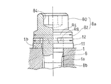
本発明の第1実施形態に係るシリンダヘッドボルトの締結構造の要部の締付け前の状態を示す断面図である。
同シリンダヘッドボルトの締結構造の要部の締付け後の状態を示す断面図である。
本発明の第2実施形態に係るシリンダヘッドボルトの締結構造の要部の締付け前の状態を示す断面図である。
同シリンダヘッドボルトの締結構造の要部の締付け後の状態を示す断面図である。
同上の第1および第2の両実施形態の実験結果によるシリンダヘッドボルトの軸力のばらつきを示す特性図である。
従来のシリンダヘッドボルトの締結構造を示す縦断面図である。
以下、本発明の好ましい実施形態について図面を参照しながら詳細に説明する。
図1に示す第1実施形態では、シリンダヘッドボルト8として、従来から用いているものをそのまま採用してシリンダヘッド1およびシリンダ3をクランクケース4に連結している。図2Aに示すように、このシリンダヘッドボルト8の回転操作部8aを除いた軸状部は、上述のように中間の円柱部8bが、回転操作部8aが設けられた上端部の外径R1および雄ねじ8c(図1)が設けられた下端部の外径よりも小さい外径R2を有するテンションボルトである。なお、シリンダヘッドボルト8の軸状部の下端部に形成された雄ねじ8cの外径は、図示していないが、上端部の外径R1とほぼ同等である。
図1に示す第1実施形態では、シリンダヘッドボルト8として、従来から用いているものをそのまま採用してシリンダヘッド1およびシリンダ3をクランクケース4に連結している。図2Aに示すように、このシリンダヘッドボルト8の回転操作部8aを除いた軸状部は、上述のように中間の円柱部8bが、回転操作部8aが設けられた上端部の外径R1および雄ねじ8c(図1)が設けられた下端部の外径よりも小さい外径R2を有するテンションボルトである。なお、シリンダヘッドボルト8の軸状部の下端部に形成された雄ねじ8cの外径は、図示していないが、上端部の外径R1とほぼ同等である。
また、このシリンダヘッドボルト8は、いわゆる座付きボルトであり、軸状部の上端部に一体形成された頭部80およびその下部の円板状のつば82を有する。頭部80は、回転操作用のトルクレンチが嵌入される六角穴84を有する。これら頭部80およびつば82が回転操作部8aを形成する。なお、平ワッシャ11としては、従来から用いている鉄系材料のものの表面に銅めっきが施されたものが用いられている。
この締結構造では、シリンダヘッドボルト8の頭部80の下部に設けられたつば82とシリンダヘッドボルト8の上面との間に、平ワッシャ11と、この平ワッシャ11の上に重ねた皿ばね10とが配置されている。皿ばね10は、シリンダヘッドボルト8の締結時に偏平形状に変形されて、その復元力により軸方向にばね力を発現するばね部材の一種である。シリンダヘッドボルト8のつば82の外径R4、すなわち回転操作部8aの外径は、シリンダヘッドボルト8の締付け前の自由状態の皿ばね10の外径R5よりも僅かに大きく、かつ平ワッシャ11の外形R3よりも小さく設定されている。
図1のシリンダヘッド1をエンジンケース2のクランクケース4に締結するに際して、シリンダヘッドボルト8の軸状部をシリンダヘッド1の挿通孔1aおよびシリンダ3の挿通孔3aに挿通したのちに、軸状部の雄ねじ8cがクランクケース4のねじ孔4aにねじ込まれる。この際、シリンダヘッドボルト8の回転操作部8aに嵌合したトルクレンチを回転操作することにより、シリンダヘッドボルト8をねじ込む。シリンダヘッドボルト8のねじ込みトルクの大きさはトルクレンチに表示される。このねじ込みトルクは軸力に比例する。
シリンダヘッドボルト8の締付けが行われてシリンダヘッドボルト8に軸力が発生する締結完了時には、図2Bに示すように、皿ばね10が上下から加圧力を受けて偏平形状に変形されて、この皿ばね10の外径R6がシリンダヘッドボルト8のつば82の外径R4よりも大きくなる。この偏平形状の皿ばね10の外径R6よりも平ワッシャ11の外径R3の方がさらに大きい。その結果、つば82と皿ばね10との接触面積S1よりも、皿ばね10と平ワッシャ11との接触面積S2が大きくなり、平ワッシャ11とシリンダヘッド1の上面の座面1bとの接触面積S3はさらに大きい。つまり、S1<S2<S3の関係となる。
これに伴って皿ばね10と平ワッシャ11との間の摩擦抵抗および平ワッシャ11とシリンダヘッド1との間の摩擦抵抗も大きくなって滑りが生じ難くなる。なお、S2をS3よりも大きくして、S1<S3<S2の関係としてもよい。摩擦抵抗は、前述のとおり、接触面積のほか、材質や表面粗さにも影響されるので、これらの影響も含めて、つば82-皿ばね10-平ワッシャ11間の摩擦抵抗の大小を設定する。
滑りは、接触面積が小さいのに伴って摩擦抵抗も小さいシリンダヘッドボルト8の回転操作部8aと皿ばね10との間に生じ易くなる。このように滑りが生じる箇所が特定されることにより、締付け後のシリンダヘッドボルト8に生じる軸力のばらつきが小さくなる。なお、ボルトに皿ばね10のようなばね部材を介在することは従来からも行われているが、従来ではボルトの緩み止めの目的でばね部材を用いているのに対し、本発明では一定の軸力を得る目的でばね部材を用いている。
この実施形態では、ばね部材として皿ばね10を用いている。皿ばね10は、シリンダヘッドボルト8の締付け前の自由状態において、シリンダヘッドボルト8の座面であるつば82の下面に対して円形の内周部で線接触することから接触面積が小さい。それに伴って、皿ばね10とつば82との間の摩擦抵抗も小さくなるので、締付け作業時のシリンダヘッドボルト8が滑りながら回転し易い。また、皿ばね10は、シリンダヘッドボルト8の座面および平ワッシャ11に接触したときに損傷を与えるような尖がった部位がない。これにより、シリンダヘッドボルト8の締付けによる押圧力が加えられたときに上下から押し潰されて、偏平形状に円滑に変形する利点がある。
シリンダヘッドボルト8として、軸状部の中間の円柱部8bが、回転操作部8aが設けられた軸状部の上端部の外径R1および雄ねじ8c(図1)が設けられた下端部の外径よりも小さい外径R2を有するテンションボルトを用いている。このテンションボルトは、シリンダヘッドボルト8の締結時に外径R2の小さい中間の円柱部8bに軸方向の大きな伸びが発生する。テンションボルトは、この復元力による大きなテンションに伴い軸方向に発生する軸力によって、図1のシリンダヘッド1とエンジンケース2とを互いに強固に連結する。
この実施形態では、エンジンケース2を構成するシリンダ3とクランクケース4とが別体となったエンジンに適用する場合を例示している。シリンダヘッドボルト8を、シリンダヘッド1およびシリンダ3の各々の挿通孔1a、3aに貫通させてクランクケース4のねじ孔4aに螺合する。これにより、シリンダヘッド1とクランクケース4とをこれらの間にシリンダ3を挟み込んだ配置で互いに連結できる。なお、エンジンケース2がシリンダ3とクランクケース4とが一体化されている場合には、シリンダヘッド1の挿通孔に挿通したシリンダヘッドボルト8がシリンダ3に設けられたねじ孔にねじ込まれて、シリンダヘッド1がエンジンケース2に締結される。
シリンダヘッドボルト8として、回転操作部8aを形成する頭部80が軸状部の上端に一体形成されたものを用いているので、スタッドボルトを用いなくてもシリンダヘッド1をエンジンケース2に締結することができる。また、このシリンダヘッドボルト8は、頭部80が軸状部の上端に一体形成されているのに加えて、頭部80の下部に円板状のつば82を有する座付きボルトであり、このつば82の外径R4が、自由状態の皿ばね10の外径R5よりも大きく設定されている。これにより、頭部80を含む回転操作部8aを介してシリンダヘッドボルト8の締付けを行った際に、皿ばね10の外径R5よりも大きい外径R4を有するシリンダヘッドボルト8の円板状のつば82による押圧力によって、皿ばね10を偏平形状に円滑に変形させることができる。
また、平ワッシャ11として、従来から用いている鉄系材料のものの表面に銅めっきが施されたものを用いている。この平ワッシャ11は、これに施された柔らかい銅めっきに皿ばね10が食い付く状態となって皿ばね10に対し滑り難くなる。これにより、滑る箇所を、シリンダヘッドボルト8の回転操作部8aと皿ばね10との間に一層確実に設定することができる。
図3Aおよび図3Bはそれぞれ本発明の第2実施形態に係るシリンダヘッドボルトの締結構造における締付け前および締結後の縦断面図である。同図において、図2Aおよび図2Bと同一若しくは相当するものに同一の符号を付して、重複する説明を省略する。この実施形態の締結構造が図2Aおよび図2Bの第1実施形態のものと相違するのは、ばね部材として、第1実施形態の皿ばね10に代えて、プリングワッシャ12を用いた構成のみである。
この締結構造では、シリンダヘッドボルト8の頭部80の下部に設けられたつば82とシリンダヘッドボルト8の上面との間に、平ワッシャ11と、この平ワッシャ11の上に重ねたスプリングワッシャ12とが配置されている。スプリングワッシャ12は、シリンダヘッドボルト8の締結時に偏平形状に変形されて、その復元力により軸方向にばね力を発現するばね部材10の一種である。図3Aに示すように、シリンダヘッドボルト8のつば82の外径R4は、シリンダヘッドボルト8の締付け前の自由状態のスプリングワッシャ12の外径R7よりも僅かに大きく、かつ平ワッシャ11の外形R3よりも小さく設定されている。
したがって、この実施形態の締結構造においても第1実施形態で説明したとほぼ同様の効果を得ることができる。すなわち、シリンダヘッドボルト8の締付けが行われてシリンダヘッドボルト8に軸力が発生する締結完了時には、図3Bに示すように、スプリングワッシャ12が上下から加圧力を受けて偏平な形状に変形されて、このスプリングワッシャ12の外径R8がシリンダヘッドボルト8のつば82の外径R4よりも大きくなる。その結果、スプリングワッシャ12と平ワッシャ11との接触面積が大きくなり、これに伴ってスプリングワッシャ12と平ワッシャ11との間の摩擦抵抗も大きくなって滑りが生じ難くなる。滑りは、接触面積が小さいのに伴って摩擦抵抗も小さいシリンダヘッドボルト8の回転操作部8aとスプリングワッシャ12との間に生じ易くなる。
このように滑りが生じる箇所が特定されることにより、締付け後のシリンダヘッドボルト8に生じる軸力のばらつきが少なくなる。なお、第2実施形態においても、スプリングワッシャ12は、従来のようにボルトの緩み止めを目的として用いられるのとは異なり、ボルトに発生する軸力をばらつきなく一定にするために用いている。
図4は、第1および第2の両実施形態の実験結果によるシリンダヘッドボルトの軸力のばらつきを示す特性図である。図4のAは第1実施形態の実験結果を示し、Bは第2実施形態の実験結果を示している。なお、Cは比較のために示した図5の従来の締結構造の実験結果による特性曲線である。黒丸は平均値を示す。シリンダヘッドボルト8は全て一定のトルクで締めつけた。同図から明らかなように、第1実施形態の締結構造ではシリンダヘッドボルト8に発生する軸力のばらつきが従来に比較して大幅に低減することが確認できた。また、第2実施形態の締結構造では、第1実施形態の締結構造よりもシリンダヘッドボルト8に発生する軸力のばらつきが若干多いが、従来の締結構造と比較すれば、シリンダヘッドボルト8に発生する軸力のばらつきが相当に低減している。
本発明はスタッドボルトの締結構造にも適用できる。その場合、スタッドボルトの上端部に螺合するナットが回転操作部を形成する。
なお、本発明は上述した実施形態に限らず、本発明の要旨を逸脱しない範囲内で、種々の追加、変更または削除が可能であり、そのようなものも本発明の範囲内に含まれる。
1 シリンダヘッド
1b 座面
2 エンジンケース
3 シリンダ
4 クランクケース
8 シリンダヘッドボルト
8a 回転操作部
8b 円柱部
8c 雄ねじ
80 頭部
82 つば
10 皿ばね(ばね部材)
11 平ワッシャ
12 スプリングワッシャ(ばね部材)
1b 座面
2 エンジンケース
3 シリンダ
4 クランクケース
8 シリンダヘッドボルト
8a 回転操作部
8b 円柱部
8c 雄ねじ
80 頭部
82 つば
10 皿ばね(ばね部材)
11 平ワッシャ
12 スプリングワッシャ(ばね部材)
Claims (7)
- シリンダヘッドに挿通したシリンダヘッドボルトを、シリンダおよびクランクケースからなるエンジンケースに螺合させることにより、前記シリンダヘッドを前記エンジンケースに締結する構造であって、
前記シリンダヘッドボルトの頭部に設けられた回転操作部と前記シリンダヘッドの上面との間に、平ワッシャと、その上に重ねた軸方向にばね力を発現するばね部材とが配置されて、前記シリンダヘッドボルトの前記回転操作部と前記ばね部材との摩擦抵抗が、前記ばね部材と前記平ワッシャとの摩擦抵抗および前記平ワッシャと前記シリンダヘッド上の座面との摩擦抵抗よりも小さく設定されているシリンダヘッドボルトの締結構造。 - 請求項1に記載の締結構造において、前記ばね部材は皿ばねであり、締結完了時に前記皿ばねの外径が回転操作部の外径よりも大きく設定されているシリンダヘッドボルトの締結構造。
- 請求項1または2に記載の締結構造であって、前記シリンダヘッドボルトは、中間の円柱部が、前記回転操作部が設けられた上端部および雄ねじが設けられた下端部よりも小さい外径を有するテンションボルトであるシリンダヘッドボルトの締結構造。
- 請求項1から3のいずれか一項に記載の締結構造であって、前記シリンダヘッドボルトは前記シリンダを貫通して前記クランクケースに螺合されているシリンダヘッドボルトの締結構造。
- 請求項1から4のいずれか一項に記載の締結構造であって、前記シリンダヘッドボルトは前記回転操作部を形成する頭部が一体形成されているシリンダヘッドボルトの締結構造。
- 請求項5に記載の締結構造であって、前記シリンダヘッドボルトは、頭部の下部に円板状のつばを有する座付きボルトであり、前記つばの外径が、自由状態の前記ばね部材の外径よりも大きいシリンダヘッドボルトの締結構造。
- 請求項1から6のいずれか一項に記載の締結構造であって、前記平ワッシャは鉄系材料に銅めっきが施されたものであるシリンダヘッドボルトの締結構造。
Priority Applications (3)
| Application Number | Priority Date | Filing Date | Title |
|---|---|---|---|
| CN201480044543.1A CN105452684B (zh) | 2013-08-26 | 2014-07-25 | 气缸盖螺栓的紧固构造 |
| EP14840184.7A EP3040564B1 (en) | 2013-08-26 | 2014-07-25 | Tightening structure for cylinder head bolt |
| US15/012,697 US9897036B2 (en) | 2013-08-26 | 2016-02-01 | Tightening structure for cylinder head bolt |
Applications Claiming Priority (2)
| Application Number | Priority Date | Filing Date | Title |
|---|---|---|---|
| JP2013174584A JP6178671B2 (ja) | 2013-08-26 | 2013-08-26 | シリンダヘッドボルトの締結構造 |
| JP2013-174584 | 2013-08-26 |
Related Child Applications (1)
| Application Number | Title | Priority Date | Filing Date |
|---|---|---|---|
| US15/012,697 Continuation US9897036B2 (en) | 2013-08-26 | 2016-02-01 | Tightening structure for cylinder head bolt |
Publications (1)
| Publication Number | Publication Date |
|---|---|
| WO2015029663A1 true WO2015029663A1 (ja) | 2015-03-05 |
Family
ID=52586237
Family Applications (1)
| Application Number | Title | Priority Date | Filing Date |
|---|---|---|---|
| PCT/JP2014/069719 Ceased WO2015029663A1 (ja) | 2013-08-26 | 2014-07-25 | シリンダヘッドボルトの締結構造 |
Country Status (5)
| Country | Link |
|---|---|
| US (1) | US9897036B2 (ja) |
| EP (1) | EP3040564B1 (ja) |
| JP (1) | JP6178671B2 (ja) |
| CN (1) | CN105452684B (ja) |
| WO (1) | WO2015029663A1 (ja) |
Cited By (1)
| Publication number | Priority date | Publication date | Assignee | Title |
|---|---|---|---|---|
| US20200047814A1 (en) * | 2018-08-08 | 2020-02-13 | Suzuki Motor Corporation | Assembling structure of engine and vehicle |
Families Citing this family (4)
| Publication number | Priority date | Publication date | Assignee | Title |
|---|---|---|---|---|
| CN106758566A (zh) * | 2017-03-15 | 2017-05-31 | 山东远大特材科技股份有限公司 | 一种镶心式高锰钢辙叉结构 |
| CN108035958A (zh) * | 2018-01-17 | 2018-05-15 | 中国重汽集团济南动力有限公司 | 一种具有安全泄压功能的螺栓组件 |
| US11047417B2 (en) * | 2018-10-11 | 2021-06-29 | GM Global Technology Operations LLC | Fastening assembly |
| EP4421334B1 (en) * | 2023-02-23 | 2025-09-03 | Goodrich Actuation Systems SAS | Threaded fastener |
Citations (4)
| Publication number | Priority date | Publication date | Assignee | Title |
|---|---|---|---|---|
| JPS61136013A (ja) * | 1984-12-06 | 1986-06-23 | 株式会社 佐賀鉄工所 | 座金の共回り防止構造 |
| JPH0240949U (ja) * | 1988-09-13 | 1990-03-20 | ||
| JP3043382U (ja) * | 1997-05-13 | 1997-11-18 | 株式会社音戸工作所 | 座金付きツーピースナット及び座金付きツーピースフランジ付きナット |
| JP2001187911A (ja) * | 1999-12-28 | 2001-07-10 | Fukasawa:Kk | ねじ締結構造 |
Family Cites Families (30)
| Publication number | Priority date | Publication date | Assignee | Title |
|---|---|---|---|---|
| JPS5197603U (ja) * | 1975-02-04 | 1976-08-05 | ||
| NL188659C (nl) | 1975-02-21 | 1992-08-17 | Shell Int Research | Werkwijze voor het ontzwavelen van koolwaterstofolien. |
| US4183699A (en) * | 1978-05-18 | 1980-01-15 | Donan David C Jr | Washer/gasket for mine roof bolt assembly |
| FR2528511A1 (fr) * | 1982-06-14 | 1983-12-16 | Peugeot | Chapeau de palier pour arbre a cames en tete de moteur a combustion interne, et moteur correspondant |
| JPS60180831U (ja) * | 1984-05-10 | 1985-11-30 | アイシン精機株式会社 | ピンスライド型デイスクブレ−キにおけるピンブ−ツの保護構造 |
| US4884930A (en) * | 1987-09-03 | 1989-12-05 | Camloc Gmbh | Panel fastener with friction cones |
| DE3869528D1 (de) * | 1987-09-14 | 1992-04-30 | Sanden Corp | Befestigung eines kraftfahrzeugkompressors fuer eine klimaanlage. |
| US5105777A (en) * | 1988-05-20 | 1992-04-21 | Tecumseh Products Company | Metal head gasket with push rod guides |
| JPH0240949A (ja) | 1988-07-30 | 1990-02-09 | Sony Corp | メモリ装置 |
| US4984938A (en) * | 1988-08-25 | 1991-01-15 | H&S Machine & Supply Company, Inc. | Coated washer for an anchor bolt system |
| CA2122631A1 (en) * | 1991-11-01 | 1993-05-13 | Norman Leslie Matthews | Fastener bearing assembly |
| US5709516A (en) * | 1994-04-18 | 1998-01-20 | General Electric Company | Washer faced spring assembly |
| US5746558A (en) * | 1996-07-24 | 1998-05-05 | Lockheed Martin Corporation | Locking apparatus for fastening system |
| US5730568A (en) * | 1996-10-03 | 1998-03-24 | Mcgard, Inc. | Anti-galling fastener |
| JP3305615B2 (ja) | 1997-04-21 | 2002-07-24 | 本田技研工業株式会社 | ボルト締付け方法 |
| DE29720094U1 (de) * | 1997-11-12 | 1999-03-18 | ITW Automotive Products GmbH & Co. KG, 58642 Iserlohn | Befestigungsvorrichtung |
| US6435791B1 (en) * | 2000-05-19 | 2002-08-20 | Maclean-Fogg Company | Wheel fastener assemblies |
| US7497653B2 (en) * | 2001-08-20 | 2009-03-03 | Maclean-Fogg Company | Locking fastener assembly |
| US6609868B2 (en) * | 2001-12-06 | 2003-08-26 | John K. Junkers | Washer, fastener provided with a washer, and method of fastening with the use of the washer |
| US6827359B2 (en) * | 2002-06-03 | 2004-12-07 | Arvinmeritor Technology, Llc. | Non-drive front axle steering knuckle |
| US6729819B2 (en) * | 2002-07-03 | 2004-05-04 | Applied Bolting Technology Products, Inc. | Bolt lubricating device and method |
| KR20060095123A (ko) * | 2005-02-28 | 2006-08-31 | 주식회사 일진글로벌 | 구동륜의 차축 조립체 |
| AT9916U1 (de) * | 2006-08-16 | 2008-05-15 | Leobersdorfer Maschf | Mehrstufiger verdichter |
| DE102006041860B4 (de) * | 2006-09-06 | 2009-05-14 | Sfs Intec Holding Ag | Schraube und deren Kombination mit einer konischen Dichtscheibe |
| WO2009145938A1 (en) * | 2008-05-28 | 2009-12-03 | Hunter Douglas Industries B.V. | Countersunk fastener assemblies, panel mounting systems, and methods |
| US8281603B2 (en) * | 2008-08-11 | 2012-10-09 | United Technologies Corporation | Fastener assembly for connecting rocket engine nozzles |
| JP5029537B2 (ja) * | 2008-08-26 | 2012-09-19 | 三菱自動車工業株式会社 | エンジン本体構造 |
| DE102009023721A1 (de) * | 2009-06-03 | 2010-12-09 | Neumayer Tekfor Holding Gmbh | Befestigungsvorrichtung |
| JP5903852B2 (ja) * | 2011-11-29 | 2016-04-13 | スズキ株式会社 | 内燃機関のクランクケース構造 |
| DE102012100228A1 (de) * | 2012-01-12 | 2013-07-18 | Kamax Holding Gmbh & Co. Kg | Schraube mit einer Kopfauflagefläche mit Schmiermitteltaschen |
-
2013
- 2013-08-26 JP JP2013174584A patent/JP6178671B2/ja active Active
-
2014
- 2014-07-25 EP EP14840184.7A patent/EP3040564B1/en active Active
- 2014-07-25 CN CN201480044543.1A patent/CN105452684B/zh not_active Expired - Fee Related
- 2014-07-25 WO PCT/JP2014/069719 patent/WO2015029663A1/ja not_active Ceased
-
2016
- 2016-02-01 US US15/012,697 patent/US9897036B2/en not_active Expired - Fee Related
Patent Citations (4)
| Publication number | Priority date | Publication date | Assignee | Title |
|---|---|---|---|---|
| JPS61136013A (ja) * | 1984-12-06 | 1986-06-23 | 株式会社 佐賀鉄工所 | 座金の共回り防止構造 |
| JPH0240949U (ja) * | 1988-09-13 | 1990-03-20 | ||
| JP3043382U (ja) * | 1997-05-13 | 1997-11-18 | 株式会社音戸工作所 | 座金付きツーピースナット及び座金付きツーピースフランジ付きナット |
| JP2001187911A (ja) * | 1999-12-28 | 2001-07-10 | Fukasawa:Kk | ねじ締結構造 |
Cited By (2)
| Publication number | Priority date | Publication date | Assignee | Title |
|---|---|---|---|---|
| US20200047814A1 (en) * | 2018-08-08 | 2020-02-13 | Suzuki Motor Corporation | Assembling structure of engine and vehicle |
| US10960930B2 (en) * | 2018-08-08 | 2021-03-30 | Suzuki Motor Corporation | Assembling structure of engine and vehicle |
Also Published As
| Publication number | Publication date |
|---|---|
| JP2015042887A (ja) | 2015-03-05 |
| EP3040564A1 (en) | 2016-07-06 |
| CN105452684B (zh) | 2018-01-30 |
| EP3040564A4 (en) | 2017-04-05 |
| JP6178671B2 (ja) | 2017-08-09 |
| US20160146149A1 (en) | 2016-05-26 |
| EP3040564B1 (en) | 2020-12-30 |
| CN105452684A (zh) | 2016-03-30 |
| US9897036B2 (en) | 2018-02-20 |
Similar Documents
| Publication | Publication Date | Title |
|---|---|---|
| JP6178671B2 (ja) | シリンダヘッドボルトの締結構造 | |
| US9322426B2 (en) | Nut and sleeve fastener | |
| JP5787197B2 (ja) | 締結部材 | |
| WO2018154795A1 (ja) | 締結構造 | |
| TWI580603B (zh) | 自行車用鏈輪 | |
| JP2015203492A (ja) | 緩み止めナット | |
| JP6039841B1 (ja) | 緩み止めナット | |
| JP3155204U (ja) | 偏心ロックナット | |
| JP6055079B2 (ja) | 取付構造 | |
| CN106104068B (zh) | 减振器的制造方法 | |
| KR101628978B1 (ko) | 풀림방지 와셔 | |
| JP6094347B2 (ja) | ボールねじ装置用ロックナット及びボールねじ装置 | |
| JP2012082871A (ja) | 締結部材 | |
| JP5802772B2 (ja) | ナット及びナット締め付け具並びにボルト及びボルト締め付け具 | |
| EA020594B1 (ru) | Состоящий из нескольких частей винтовой элемент, винтовое соединение и способ изготовления винтового элемента | |
| JP5817039B2 (ja) | 弛み止め締付部材又は弛み止め座金 | |
| JP2017003103A (ja) | 弛み止め締結部材 | |
| JP2015075235A (ja) | 締結部材 | |
| JP6295102B2 (ja) | スタッドボルト弛め具 | |
| JP2015165154A (ja) | 緩み止めナット | |
| JP3183487U (ja) | 軸力表示座金付ナット | |
| JP3179117U (ja) | ナットの緩み止めワッシャー | |
| US20160348702A1 (en) | Device configured for preloading bearing interfaces coupling concentrically arranged tubes | |
| JP5451548B2 (ja) | 袋ナット | |
| JP2014202271A (ja) | 軸継手 |
Legal Events
| Date | Code | Title | Description |
|---|---|---|---|
| WWE | Wipo information: entry into national phase |
Ref document number: 201480044543.1 Country of ref document: CN |
|
| 121 | Ep: the epo has been informed by wipo that ep was designated in this application |
Ref document number: 14840184 Country of ref document: EP Kind code of ref document: A1 |
|
| REEP | Request for entry into the european phase |
Ref document number: 2014840184 Country of ref document: EP |
|
| WWE | Wipo information: entry into national phase |
Ref document number: 2014840184 Country of ref document: EP |
|
| NENP | Non-entry into the national phase |
Ref country code: DE |