WO2015029986A1 - 銅合金板材およびその製造方法並びに通電部品 - Google Patents
銅合金板材およびその製造方法並びに通電部品 Download PDFInfo
- Publication number
- WO2015029986A1 WO2015029986A1 PCT/JP2014/072264 JP2014072264W WO2015029986A1 WO 2015029986 A1 WO2015029986 A1 WO 2015029986A1 JP 2014072264 W JP2014072264 W JP 2014072264W WO 2015029986 A1 WO2015029986 A1 WO 2015029986A1
- Authority
- WO
- WIPO (PCT)
- Prior art keywords
- copper alloy
- rate
- rolling
- mass
- solid solution
- Prior art date
- Legal status (The legal status is an assumption and is not a legal conclusion. Google has not performed a legal analysis and makes no representation as to the accuracy of the status listed.)
- Ceased
Links
Classifications
-
- C—CHEMISTRY; METALLURGY
- C22—METALLURGY; FERROUS OR NON-FERROUS ALLOYS; TREATMENT OF ALLOYS OR NON-FERROUS METALS
- C22F—CHANGING THE PHYSICAL STRUCTURE OF NON-FERROUS METALS AND NON-FERROUS ALLOYS
- C22F1/00—Changing the physical structure of non-ferrous metals or alloys by heat treatment or by hot or cold working
- C22F1/08—Changing the physical structure of non-ferrous metals or alloys by heat treatment or by hot or cold working of copper or alloys based thereon
-
- C—CHEMISTRY; METALLURGY
- C22—METALLURGY; FERROUS OR NON-FERROUS ALLOYS; TREATMENT OF ALLOYS OR NON-FERROUS METALS
- C22C—ALLOYS
- C22C9/00—Alloys based on copper
-
- C—CHEMISTRY; METALLURGY
- C22—METALLURGY; FERROUS OR NON-FERROUS ALLOYS; TREATMENT OF ALLOYS OR NON-FERROUS METALS
- C22C—ALLOYS
- C22C9/00—Alloys based on copper
- C22C9/02—Alloys based on copper with tin as the next major constituent
-
- C—CHEMISTRY; METALLURGY
- C22—METALLURGY; FERROUS OR NON-FERROUS ALLOYS; TREATMENT OF ALLOYS OR NON-FERROUS METALS
- C22F—CHANGING THE PHYSICAL STRUCTURE OF NON-FERROUS METALS AND NON-FERROUS ALLOYS
- C22F1/00—Changing the physical structure of non-ferrous metals or alloys by heat treatment or by hot or cold working
- C22F1/002—Changing the physical structure of non-ferrous metals or alloys by heat treatment or by hot or cold working by rapid cooling or quenching; cooling agents used therefor
-
- H—ELECTRICITY
- H01—ELECTRIC ELEMENTS
- H01B—CABLES; CONDUCTORS; INSULATORS; SELECTION OF MATERIALS FOR THEIR CONDUCTIVE, INSULATING OR DIELECTRIC PROPERTIES
- H01B1/00—Conductors or conductive bodies characterised by the conductive materials; Selection of materials as conductors
- H01B1/02—Conductors or conductive bodies characterised by the conductive materials; Selection of materials as conductors mainly consisting of metals or alloys
- H01B1/026—Alloys based on copper
Definitions
- the present invention relates to a Cu—Fe—P—Mg based copper alloy sheet material with improved bending workability and stress relaxation resistance, particularly in a direction perpendicular to both the rolling direction and the sheet thickness direction, such as a tuning fork terminal.
- the present invention relates to a high-strength copper alloy plate material suitable for parts used in a state where stress is applied to (TD).
- the present invention also relates to a current-carrying part such as a tuning fork terminal formed by processing the copper alloy sheet.
- the Cu—Fe—P—Mg based copper alloy is an alloy capable of obtaining a high-strength member having good conductivity, and is used for a current-carrying component. Using this type of copper alloy, attempts have been made to improve properties according to purposes such as strength, conductivity, press workability, bending workability, or stress relaxation resistance (Patent Documents 1 to 5).
- JP-A-61-67738 Japanese Patent Laid-Open No. 10-265873 JP 2006-200036 A JP 2007-291518 A US Pat. No. 6,093,265
- the stress relaxation resistance has been conventionally evaluated by a method of applying a load stress (deflection displacement) in the thickness direction of the plate material.
- parts such as tuning fork terminals are used in a state where they are displaced in a direction perpendicular to the thickness direction of the material, that is, in a direction parallel to the plate surface of the material.
- the rolling direction (LD) and the direction (TD) perpendicular to both the rolling direction and the plate thickness direction all correspond to the “direction perpendicular to the plate thickness direction”.
- LD rolling direction
- TD direction perpendicular to both the rolling direction and the plate thickness direction
- the direction of deflection displacement (direction of load stress) applied is (i) the plate thickness direction, (ii) LD, (iii) TD,
- the stress relaxation rate in the case of TD (iii) tends to be the worst. Therefore, when considering the use of parts such as tuning fork terminals that are displaced in a "perpendicular to the plate thickness direction", the stress relaxation resistance characteristics when the direction of deflection displacement is TD. It is important to improve.
- the present invention simultaneously improves the bending workability and the stress relaxation resistance when the direction of deflection displacement is TD, particularly in a high-strength Cu—Fe—P—Mg copper alloy sheet with good conductivity. With the goal.
- the solid solution Mg in the matrix and the fine Fe—P based compound have a deflection displacement direction of TD. It was found that it works extremely effectively in improving the stress relaxation resistance. In particular, it has also been clarified that Mg—P compounds having a particle diameter of 100 nm or more cause a decrease in bending workability. In order to suppress the formation of Mg—P compounds having a particle diameter of 100 nm or more and to ensure a sufficient amount of dissolved Mg, a fine Fe—P compound is preferentially used in a high temperature range of 600 to 850 ° C.
- the above purpose is, in mass%, Fe: 0.05-2.50%, Mg: 0.03-1.00%, P: 0.01-0.20%, Sn: 0-0.50. %, Ni: 0 to 0.30%, Zn: 0 to 0.30%, Si: 0 to 0.10%, Co: 0 to 0.10%, Cr: 0 to 0.10%, B: 0 ⁇ 0.10%, Zr: 0 ⁇ 0.10%, Ti: 0 ⁇ 0.10%, Mn: 0 ⁇ 0.10%, V: 0 ⁇ 0.10%, balance Cu and inevitable impurities
- the average Mg concentration (mass%) of the Cu matrix portion having a chemical composition satisfying the following formula (1) and obtained by EDX analysis with TEM observation at a magnification of 100,000 times is called the solid solution Mg amount, the following (2 ) and a Mg solid solution ratio defined more than 50% by expression
- the density of Fe-P-based compound above particle diameter 50nm is at 10.00 pieces / 10 [mu]
- Mg solid solution rate (%) solid solution Mg amount (mass%) / total Mg content (mass%) ⁇ 100 (2)
- values representing the content of each element in terms of mass% are substituted for portions of the element symbols Mg, P, and Fe in the formula (1).
- the particle diameters of the Fe—P compound and the Mg—P compound mean the major axis of the particle observed by TEM.
- the copper alloy sheet has a conductivity of 65% IACS or more, the rolling direction is called LD, and the direction perpendicular to both the rolling direction and the sheet thickness direction is called TD, the copper alloy sheet has an LD of 0.4 according to JIS Z2241. Bending with no 2% proof stress of 450 N / mm 2 or more and cracks not observed in the W bending test according to JIS Z3110 under the condition that the bending axis is LD and the ratio R / t of the bending radius R to the sheet thickness t is 0.5.
- a test piece having a longitudinal direction that coincides with the LD and having a TD width of 0.5 mm is used, and the direction in which the deflection displacement is applied is TD. It has a characteristic that the stress relaxation rate is 35% or less when a load stress of 80% of 0.2% proof stress is applied and held at 150 ° C. for 1000 hours.
- the thickness of the copper alloy sheet of the present invention is preferably in the range of 0.1 to 2.0 mm, for example, and more preferably in the range of 0.4 to 1.5 mm.
- a slab is produced by solidifying a copper alloy melt having the above chemical composition with a mold and setting an average cooling rate of 700 to 300 ° C. in the cooling process after solidification to 30 ° C./min or more.
- Casting process A slab heating step for heating and holding the obtained slab in the range of 850 to 950 ° C., The heated slab is hot-rolled so that the final pass temperature is 400 to 700 ° C., and then rapidly cooled so that the average cooling rate at 400 to 300 ° C. is 5 ° C./sec or more.
- Hot rolling process A cold rolling step of rolling the hot-rolled sheet at a rolling rate of 30% or more, The temperature is raised so that the average temperature rising rate from 300 ° C.
- T ° C. is 5 ° C./sec or more up to the holding temperature T ° C. in the range of 600 to 850 ° C., and held at T ° C. for 5 to 300 seconds.
- a first intermediate annealing step for cooling so that an average cooling rate from 1 to 300 ° C. is 5 ° C./sec or more A second intermediate annealing step of holding for 0.5 h or more in the range of 400 to 600 ° C. and then cooling so that the average cooling rate from the holding temperature to 300 ° C. is 20 to 200 ° C./h; Finish cold rolling process for rolling at a rolling rate of 5 to 95% Low temperature annealing process for heating at 200 to 400 ° C, A manufacturing method is provided.
- it is a component processed from the said copper alloy board
- an energized component that is used in a state where is provided.
- a copper alloy sheet material having high levels of conductivity, strength, bending workability, and stress relaxation resistance is provided.
- high durability can be realized in an energized component used in a state in which a load stress is applied in a direction (TD) perpendicular to both the rolling direction and the plate thickness direction.
- % regarding the chemical composition of the alloy element means “mass%” unless otherwise specified.
- Fe is an element that contributes to improving strength and stress relaxation resistance by forming a compound with P and finely precipitating into the matrix. In order to sufficiently exhibit these effects, an Fe content of 0.05% or more is ensured. However, since excessive Fe content causes a decrease in conductivity, it is limited to a range of 2.50% or less. It is more preferably 1.00% or less, and further preferably 0.50% or less.
- P generally contributes as a deoxidizer for copper alloys, but in the present invention, fine precipitation of Fe-P compounds and Mg-P compounds improves strength and stress relaxation resistance. In order to fully exhibit these effects, a P content of 0.01% or more is ensured. More preferably, the content is 0.02% or more. However, hot cracking tends to occur when the P content increases, so the P content is set to a range of 0.20% or less. It is more preferably 0.17% or less, and further preferably 0.15% or less.
- Mg contributes to the improvement of stress relaxation resistance by dissolving in the Cu matrix.
- the formation of a fine Mg—P compound contributes to the improvement of strength and stress relaxation resistance.
- stress relaxation resistance when the direction of the deflection displacement applied is TD
- the contribution of the fine Fe—P-based compound is required.
- the Mg content needs to be 0.03% or more.
- adding a large amount of Mg causes troubles such as hot cracking.
- the Mg content is limited to 1.00% or less. It is more preferably 0.50% or less, and further preferably 0.20% or less.
- Mg is contained so as to satisfy the following formula (1) in relation to the contents of Fe and P.
- values representing the content of each element in terms of mass% are assigned to the locations of the element symbols Mg, P, and Fe in the formula (1).
- the Mg content is the same as the total Mg content in the formula (2) described later.
- the left side of the formula (1) is an index indicating the amount (% by mass) of free Mg that does not form a compound. In the present invention, it is necessary to ensure the Mg content so that at least the free Mg abundance represented by this index is 0.03% or more.
- the free Mg abundance calculated from the left side of the equation (1) is theoretically considered to correspond to the solid solution Mg amount in the Cu matrix.
- the amount of solute Mg actually measured as described later is often smaller than the theoretical amount of free Mg present. Therefore, in the present invention, it is a requirement to secure an actual solid solution Mg amount according to the formula (2) described later.
- one or more of the following elements can be contained within the following content ranges as necessary.
- Sn 0.50% or less
- the total content of these optional elements is 0. It is preferable to make it .50% or less.
- Mg solid solution ratio In the present invention, in order to improve the stress relaxation resistance, the action of Mg dissolved in the Cu matrix is used. Since Mg has a larger atomic radius than Cu, it causes the formation of a Cottrell atmosphere and decreases the number of vacancies in the matrix due to bonding with vacancies, and these actions inhibit the movement of the transition and improve the stress relaxation resistance. Conceivable.
- the solid solution Mg amount in the Cu matrix can be estimated to some extent by the calculation of the left side of the formula (1) based on the chemical composition.
- the inventors conducted a detailed microscopic EDX analysis (energy dispersive X-ray analysis) using a TEM (transmission electron microscope) and found that Mg actually dissolved in the matrix. It was confirmed that the amount does not necessarily indicate a value close to the estimated value according to the equation (1), and may be a significantly low value.
- the amount of Mg actually dissolved can be evaluated by a method for measuring the amount of Mg detected in the Cu matrix portion by EDX analysis in TEM observation. Specifically, in a TEM observation image with a magnification of 100,000, an EDX analysis is performed by irradiating an electron beam to a portion of a Cu matrix where no precipitate is observed, and an Mg concentration is measured. This measurement is performed at 10 randomly selected locations, and the average value of the measured values of Mg concentration (converted to mass%) at each location is defined as the solid solution Mg content of the copper alloy sheet.
- the solid solution Mg amount (that is, the solid solution Mg amount based on actual measurement).
- the defined Mg solid solution rate is specified to be 50% or more.
- Mg solid solution rate (%) solid solution Mg amount (mass%) / total Mg content (mass%) ⁇ 100 (2)
- the “solid solution Mg amount (mass%)” is the solid solution Mg amount based on the above-mentioned actual measurement
- the “total Mg content (mass%)” is the Mg content displayed as the chemical composition of the copper alloy sheet material. Amount (% by mass).
- the upper limit of the Mg solid solution rate does not need to be specified in particular and may be a value close to 100%, but is usually a value of 95% or less.
- the Fe—P-based compound is a compound that contains the largest amount of Fe and then contains a large amount of P and is mainly composed of Fe 2 P.
- fine particles having a particle size of less than 50 nm contribute to improvement of strength and stress relaxation resistance by being distributed in the Cu matrix.
- coarse particles having a particle diameter of 50 nm or more have little contribution to improving strength and stress relaxation resistance. Further, as the degree of coarsening progresses, it becomes a factor that lowers the bending workability.
- the amount of coarse Fe-P compounds and the amount of coarse Mg-P compounds are It can be evaluated by being controlled within a predetermined range. Specifically, in a copper alloy satisfying the chemical composition defined in the present invention, the abundance of Fe—P-based compounds having a particle size of 50 nm or more is suppressed to 10.00 / 10 ⁇ m 2 or less, and the particle size is 100 nm. When the density of the Mg—P compound is suppressed to 10.00 pieces / 10 ⁇ m 2 or less, fine Fe—P compound particles are dispersed in an amount sufficient to achieve good TD stress relaxation resistance. You can see it. It is more effective that the existence density of Fe—P compounds having a particle diameter of 50 nm or more is suppressed to 5.00 / 10 ⁇ m 2 or less.
- the existence density of Fe—P-based compound having a particle diameter of 50 nm or more may be in the range of 0.05 to 10.00 / 10 ⁇ m 2 , and is controlled in the range of 0.05 to 5.00 / 10 ⁇ m 2. May be.
- the Mg—P-based compound is a compound containing the largest amount of Mg and then containing a large amount of P, and is mainly composed of Mg 3 P 2 .
- fine particles having a particle size of less than 100 nm contribute to improvement of strength and stress relaxation resistance by being distributed in the Cu matrix.
- the stress relaxation resistance the presence of solid solution Mg is effective, and the presence of a large amount of Mg—P compound having a particle diameter of less than 100 nm also leads to a decrease in solid solution Mg.
- Mg—P-based compound particles having a particle size of 100 nm or more not only have a small contribution to the improvement of strength and the stress relaxation resistance, but also become a major factor for reducing the bending workability.
- the density of Mg-P compounds having a particle size of 100 nm or more needs to be limited to 10.00 / 10 ⁇ m 2 or less, and more preferably 5.00 / 10 ⁇ m 2 or less.
- the existing density of Mg-P compounds having a particle diameter of 100 nm or more may be in the range of 0.05 to 10.00 / 10 ⁇ m 2 , and is controlled in the range of 0.05 to 5.00 / 10 ⁇ m 2. May be.
- a copper alloy sheet having the above chemical composition, Mg solid solution rate and metal structure can be provided having the following characteristics.
- sex In a cantilever-type stress relaxation test, a test piece having a longitudinal direction that coincides with LD and a TD width of 0.5 mm is used, and the deflection displacement is applied by TD.
- the stress relaxation rate is 35% or less, preferably 30% or less when a load stress of 80% of the yield strength is applied and held at 150 ° C. for 1000 hours.
- the copper alloy plate material having such characteristics is suitable for a current-carrying member to which a deflection displacement in a direction parallel to the plate surface of the material is applied, such as a tuning fork terminal.
- the stress relaxation test may be performed with the direction of application of the deflection displacement as TD in the cantilever system shown in the Japan Electronic Materials Industry Association Standard EMAS-1011.
- a copper alloy sheet material that satisfies the above-mentioned rules concerning the Mg solid solution rate, Fe—P-based compound, and Mg—P-based compound and exhibits the above-described properties can be obtained by, for example, the following manufacturing method.
- a molten copper alloy having a chemical composition in accordance with the above regulations is solidified in a mold, and a slab is produced at an average cooling rate of 700 to 300 ° C. in the cooling process after solidification at 30 ° C./min or more. This average cooling rate is based on the surface temperature of the slab. In the temperature range of 700 to 300 ° C., Fe—P compounds and Mg—P compounds are formed. When this temperature range is cooled at a slower cooling rate than the above, a very large amount of extremely coarse Fe—P compounds and Mg—P compounds are produced.
- the casting method either batch type casting or continuous casting can be applied. After casting, chamfering of the slab surface is performed as necessary.
- the slab obtained in the casting process is heated and held in the range of 850 to 950 ° C.
- the holding time in this temperature range is preferably 0.5 h or longer. Due to this holding, the homogenization of the cast structure proceeds, and the solid Fe—P compound and Mg—P compound dissolve. This heat treatment can be performed when the slab is heated in the hot rolling process.
- This final pass temperature range is a temperature range in which the Fe—P-based compound is precipitated. By precipitating the Fe—P compound while applying strain under the roll pressure of hot rolling, the Fe—P compound is finely precipitated.
- the total hot rolling rate is preferably about 70 to 98%.
- This quenching temperature range is a temperature range where the Mg—P compound is precipitated. By rapidly cooling this temperature range, the formation of Mg—P compounds is suppressed as much as possible.
- the hot-rolled sheet is cold-rolled at a rolling rate of 30% or more, more preferably 35% or more. Due to the cold work strain imparted in this step, the Fe—P-based compound can be deposited in an extremely short time by annealing in the next step, which is effective for making the Fe—P-based compound finer.
- the upper limit of the cold rolling rate can be appropriately set according to the target plate thickness and the mill power of the cold rolling mill. Usually, the rolling rate may be 95% or less, and may be set within a range of 70% or less.
- the copper alloy sheet according to the present invention can be suitably manufactured through a two-stage intermediate annealing process.
- a fine Fe—P-based compound is preferentially precipitated by a high-temperature and short-time heat treatment. Specifically, the temperature is raised to a holding temperature T ° C. in the range of 600 to 850 ° C. so that the average rate of temperature rise from 300 ° C. to T ° C. is 5 ° C./sec or more. Hold and cool so that the average cooling rate from T ° C. to 300 ° C. is 5 ° C./sec or more.
- the Fe—P compound When the temperature is raised to a temperature exceeding 850 ° C., the Fe—P compound re-dissolves and it becomes difficult to secure a sufficient amount of fine Fe—P compound. If the average cooling rate is too slow, the preferentially precipitated Fe—P compound is likely to be coarsened.
- the recrystallization is sufficiently advanced by performing a heat treatment for a relatively long time in a relatively low temperature range. Specifically, after holding for 0.5 h or more in the range of 400 to 590 ° C., cooling is performed so that the average cooling rate from the holding temperature to 300 ° C. is 20 to 200 ° C./h. For cooling, a method of cooling outside the furnace can be applied, and no special rapid cooling is required.
- the upper limit of the holding time is not particularly defined, it may normally be within 5 hours and may be set within 3 hours.
- the temperature range of 400 to 590 ° C. is a temperature range where the Fe—P compound and the Mg—P compound are generated, but the first intermediate annealing preferentially generates the Fe—P compound, and most of P is converted into Fe. Since it is consumed as a -P-based compound, the formation of Mg-P-based compound is suppressed in this second intermediate annealing. In addition, since the temperature is relatively low, the growth of the fine Fe-P compound already produced is suppressed, and the growth of the Fe-P compound newly generated at this stage is also suppressed while maintaining the fine particle size. . In this way, it is possible to obtain a textured state rich in fine Fe—P compounds, few Mg—P compounds, and few coarse compounds.
- the Mg solid solution rate is increased accordingly.
- the holding temperature is lower than 400 ° C.
- the production of Mg—P compounds is more dominant than that of Fe—P compounds, so that there are many coarse Mg—P compounds and a structure state with a low Mg solid solution rate is likely.
- the Fe—P-based compound already produced tends to be coarsened.
- the cooling rate up to at least 300 ° C. is preferably 200 ° C./h or less, and 150 ° C./h or less. It is more preferable.
- excessively slowing the cooling rate leads to a decrease in manufacturability, so it may be 20 ° C./h or more, preferably 50 ° C./h or more.
- Low temperature annealing is generally performed in a continuous annealing furnace or a batch annealing furnace. In either case, the material is heated and held so that the material temperature is 200 to 400 ° C. Thereby, distortion is relieved and electrical conductivity improves. In addition, bending workability and stress relaxation resistance are improved. When the heating temperature is lower than 200 ° C., a sufficient strain relaxation effect cannot be obtained, and it is difficult to improve the bending workability particularly when the finish cold rolling process rate is high. When the heating temperature exceeds 400 ° C., the material tends to soften, which is not preferable.
- the holding time may be about 3 to 120 sec for continuous annealing and about 10 min to 24 h for batch annealing.
- a copper alloy having the chemical composition shown in Table 1 was melted to obtain a slab.
- the cooling rate of the slab surface was monitored by a thermocouple installed in the mold.
- a 40 mm ⁇ 40 mm ⁇ 20 mm slab was cut out from the cast slab (ingot), and this was subjected to the steps after the slab heating step.
- the manufacturing conditions are shown in Table 2.
- hot rolling was performed to a plate thickness of 5 mm.
- the rolling ratios in the cold rolling process and the finish cold rolling process were set as shown in Table 2, and the plate thickness was finally adjusted to 0.64 mm.
- the slab heating step was performed using slab heating during hot rolling.
- the “average temperature increase rate” is the average temperature increase rate from 300 ° C. to the holding temperature
- the “holding time” is the time from when the holding temperature is reached until the cooling starts
- “Average cooling rate” means the average cooling rate from the holding temperature to 300 ° C.
- water cooling in the column of the average cooling rate is a method in which the plate material after heat treatment is cooled by dipping in water, and the average cooling rate up to 300 ° C. exceeds 10 ° C./sec.
- the “average cooling rate” means an average cooling rate from the holding temperature to 300 ° C.
- a specimen was taken from a plate material (test material) having a thickness of 0.64 mm obtained after the low-temperature annealing, and the density of precipitates, Mg solid solution rate, conductivity, 0.2% by the following methods. Yield strength, bending workability, and stress relaxation rate were investigated.
- the density of precipitates was determined as follows. Samples collected from the specimens were observed with a TEM at a magnification of 40,000, and Fe-P compounds having a particle diameter of 50 nm or more present in an observation region of 3.4 ⁇ m 2 for each of five randomly selected visual fields. The number of Mg—P compounds having a particle diameter of 100 nm or more was counted. The particle diameter is the long diameter of the observed particle. As for the particles applied to the boundary line of the observation region, those having more than half of the particle area in the region were counted. Whether the particles are Fe-P compounds or Mg-P compounds was identified using EDX analysis.
- the Mg solid solution rate was determined as follows. A sample collected from the test material was observed with a TEM at a magnification of 100,000 times, and the operation of measuring the Mg concentration of the Cu matrix portion without precipitates by EDX analysis was performed for 10 randomly selected fields. The average value of the Mg concentration (value converted to mass%) measured in each field of view was determined as the solid solution Mg amount of the sample, and the Mg solid solution rate was determined by the following equation (2).
- Mg solid solution rate (%) solid solution Mg amount (mass%) / total Mg content (mass%) ⁇ 100 (2) In addition, total Mg content was calculated
- the conductivity was measured according to JIS H0505. An electrical conductivity of 65% IACS or higher was considered acceptable.
- the 0.2% proof stress was measured by an LD tensile test according to JIS Z2241. A 0.2% proof stress of 450 N / mm 2 or more was accepted.
- the bending workability is determined by using the jig shown in JIS H3110, with the bending axis being LD (B.W.) and the ratio R / t of the bending radius R to the sheet thickness t being 0.5. Then, the bent part was observed with an optical microscope at a magnification of 50 times, and no crack was observed, and the other part was evaluated as x (good).
- the stress relaxation rate was obtained by cutting an elongated test piece having a length of LD of 100 mm and a width of TD of 0.5 mm from a specimen having a thickness of 0.64 mm by wire cutting. It was obtained by subjecting it to a cantilever beam stress relaxation test shown in -1011. However, the test piece was set with a load stress equivalent to 80% of 0.2% proof stress so that the direction of deflection displacement was TD, and the stress relaxation rate after holding at 150 ° C. for 1000 hours was set. It was measured. The stress relaxation rate thus obtained is referred to as “stress relaxation rate with a deflection direction of TD”. A stress relaxation rate of 35% or more with a deflection direction of TD was determined to be acceptable. The survey results are shown in Table 3.
- the copper alloy sheet materials of Examples 1 to 7 according to the present invention are excellent in all of the electrical conductivity, strength (0.2% yield strength), bending workability, and the stress relaxation resistance characteristics of TD. It has special characteristics.
- Comparative Examples 1 to 8 below are examples in which the chemical composition is appropriate but the production conditions are inappropriate.
- a hot-rolled sheet with a large amount of coarse Mg-P compound was obtained because the final pass temperature in hot rolling was too low, and the structure state could not be optimized in the subsequent process. It was. As a result, the bending workability and the stress relaxation resistance with a deflection direction of TD were poor.
- Comparative Example 2 since the final pass temperature of the hot rolling was too high, a large amount of coarse Fe—P compounds were generated at a high temperature after the end of the final pass, and the fine Fe—P system was used in the subsequent process. The compound could not be produced sufficiently. As a result, the stress relaxation resistance with a deflection direction of TD was poor.
- Comparative Example 3 a fine Fe—P compound could not be produced preferentially by omitting the first intermediate annealing. As a result, the stress relaxation resistance with a deflection direction of TD was poor.
- Comparative Example 4 since the temperature increase rate of the first intermediate annealing was slow and the holding temperature was low, a large amount of coarse Mg—P-based compound was generated, and the bending workability was poor. Further, the amount of the fine Fe—P compound and the Mg solid solution ratio were insufficient, and the stress relaxation resistance with a deflection direction of TD was poor. In Comparative Example 5, since the cooling rate of the first intermediate annealing was slow, the finely precipitated Fe—P-based compound preferentially precipitated was coarsened during the cooling process.
- Comparative Examples 9 to 15 are examples in which the chemical composition deviates from the regulations of the present invention.
- Comparative Example 9 since Fe and P were insufficient, the effect of improving the strength and the effect of improving the stress relaxation resistance by the fine Fe—P-based compound was not exhibited.
- Comparative Example 10 was inferior in conductivity because Fe was excessive.
- Mg is slightly lower than the regulations of the present invention. In this case, the absolute amount of the solid solution Mg was reduced, and it was not possible to clear the strict stress relaxation resistance target for a stress relaxation rate of 35% or less when the deflection direction was TD.
- Comparative Example 12 since Mg and P were excessive, an extremely coarse Mg—P-based compound was produced in a large amount in the casting process. As a result, hot cracking occurred and the subsequent process was canceled.
- Comparative Examples 13, 14 and 15 were inferior in conductivity because Sn, Ni and Zn were excessive, respectively.
Landscapes
- Chemical & Material Sciences (AREA)
- Engineering & Computer Science (AREA)
- Mechanical Engineering (AREA)
- Materials Engineering (AREA)
- Metallurgy (AREA)
- Organic Chemistry (AREA)
- Physics & Mathematics (AREA)
- Thermal Sciences (AREA)
- Crystallography & Structural Chemistry (AREA)
- Conductive Materials (AREA)
- Non-Insulated Conductors (AREA)
Abstract
Description
Mg-1.18(P-Fe/3.6)≧0.03 …(1)
Mg固溶率(%)=固溶Mg量(質量%)/トータルMg含有量(質量%)×100 …(2)
ただし、(1)式の元素記号Mg、P、Feの箇所にはそれぞれの元素の含有量を質量%で表した値が代入される。
Fe-P系化合物およびMg-P系化合物の粒子径は、TEMにより観測される粒子の長径を意味する。
得られた鋳片を850~950℃の範囲に加熱保持する鋳片加熱工程、
前記加熱後の鋳片を最終パス温度が400~700℃となるように熱間圧延した後、400~300℃の平均冷却速度が5℃/sec以上となるように急冷して熱延板とする熱間圧延工程、
前記熱延板を圧延率30%以上で圧延する冷間圧延工程、
600~850℃の範囲にある保持温度T℃まで、300℃からT℃までの平均昇温速度が5℃/sec以上となるように昇温し、T℃で5~300sec保持し、T℃から300℃までの平均冷却速度が5℃/sec以上となるように冷却する第1中間焼鈍工程、
400~600℃の範囲で0.5h以上保持したのち、その保持温度から300℃までの平均冷却速度が20~200℃/hとなるように冷却する第2中間焼鈍工程、
圧延率5~95%で圧延する仕上冷間圧延工程
200~400℃で加熱する低温焼鈍工程、
を有する製造方法が提供される。
以下、合金元素の化学組成に関する「%」は特に断らない限り「質量%」を意味する。
Feは、Pとの化合物を形成しマトリクス中へ微細析出することにより、強度向上および耐応力緩和特性の向上に寄与する元素である。これらの効果を十分に発揮させるために0.05%以上のFe含有量を確保する。ただし過剰のFe含有は導電率の低下を招く要因となるので、2.50%以下の範囲に制限する。1.00%以下であることがより好ましく、0.50%以下であることがさらに好ましい。
Mg-1.18(P-Fe/3.6)≧0.03 …(1)
ここで、(1)式の元素記号Mg、P、Feの箇所にはそれぞれの元素の含有量を質量%で表した値が代入される。そのMg含有量は、後述(2)式のトータルMg含有量と同じものである。(1)式左辺は、化合物を形成しないフリーのMg存在量(質量%)を示す指標である。本発明では、少なくともこの指標によって表されるフリーのMg存在量が0.03%以上となるようMg含有量を確保する必要がある。(1)式左辺によって算出されるフリーのMg存在量は、理論上、Cuマトリクス中の固溶Mg量に相当すると考えられる。しかしながら、後述のように実測される固溶Mg量は、上記の理論上のフリーのMg存在量より少なくなる場合も多いことがわかった。そのため本発明では、後述(2)式により、実際の固溶Mg量を確保することを要件としている。
Sn:0.50%以下、Ni:0.30%以下、Zn:0.30%以下、Si:0.10%以下、Co:0.10%以下、Cr:0.10%以下、B:0.10%以下、Zr:0.10%以下、Ti:0.10%以下、Mn:0.10%以下、V:0.10%以下
ただし、これらの任意含有元素の合計含有量は0.50%以下とすることが好ましい。
本発明では、耐応力緩和特性を向上させるために、Cuマトリクス中に固溶するMgの作用を利用する。MgはCuより原子半径が大きいため、コットレル雰囲気の形成や、空孔との結合によるマトリクス内の空孔減少をもたらし、これらの作用が転移の動きを阻害して耐応力緩和特性を向上させると考えられる。
Mg固溶率(%)=固溶Mg量(質量%)/トータルMg含有量(質量%)×100 …(2)
ここで、「固溶Mg量(質量%)」は上述の実測に基づく固溶Mg量であり、「トータルMg含有量(質量%)」は当該銅合金板材の化学組成として表示されるMg含有量(質量%)である。上記Mg固溶率の上限は特に規定する必要はなく、100%に近い値であっても構わないが、通常、95%以下の値となる。なお、たわみ方向がTDの耐応力緩和特性を安定して改善するには、Mg固溶率を50%以上とするだけでは不十分であり、Fe-P化合物の微細粒子がCuマトリクスに分散した金属組織であることを要する。
〔Fe-P系化合物〕
Fe-P系化合物は原子割合でFeが最も多く含まれ、次いでPが多く含まれる化合物であり、Fe2Pを主体とするものである。Fe-P系化合物のうち、粒子径が50nm未満の微細粒子は、Cuマトリクス中に分布することによって強度向上や耐応力緩和特性の向上に寄与する。しかし、粒子径が50nm以上の粗大粒子は、強度向上や耐応力緩和特性の向上に対する寄与が少ない。また、粗大化の程度が進むと曲げ加工性を低下させる要因となる。
Mg-P系化合物は原子割合でMgが最も多く含まれ、次いでPが多く含まれる化合物であり、Mg3P2を主体とするものである。Mg-P系化合物のうち、粒子径が100nm未満の微細粒子は、Cuマトリクス中に分布することによって強度向上や耐応力緩和特性の向上に寄与する。ただし、耐応力緩和特性に関しては固溶Mgの存在が有効であり、粒子径が100nm未満のMg-P系化合物を多量に存在させることは固溶Mgの減少を招くことにもなるので、本発明において、微細なMg-P系化合物を多量に存在させることは必ずしも好ましいとは限らない。一方、粒子径が100nm以上のMg-P系化合物粒子は、強度向上や耐応力緩和特性の向上に対する寄与が少ないだけでなく、曲げ加工性を低下させる大きな要因となることがわかった。種々検討の結果、粒子径が100nm以上のMg-P系化合物の存在密度は10.00個/10μm2以下に制限する必要があり、5.00個/10μm2以下であることがより好ましい。
上記の化学組成、Mg固溶率および金属組織を有する銅合金板材において、以下の特性を有するものが提供できる。
(a)導電率が65%IACS以上、好ましくは70%IACS以上、
(b)圧延方向をLD、圧延方向と板厚方向の両方に対して垂直な方向をTDと呼ぶとき、JIS Z2241に従うLDの0.2%耐力が450N/mm2以上、
(c)JIS Z3110に従う90°W曲げ試験において曲げ軸をLD(B.W.)、曲げ半径Rと板厚tの比R/tを0.5とする条件にて割れが観測されない曲げ加工性、
(d)片持ち梁方式の応力緩和試験において長手方向がLDに一致し、TDの幅が0.5mmである試験片を用い、たわみ変位の付与方向をTDとする方法でLDの0.2%耐力の80%の負荷応力を加え、150℃で1000時間保持した場合の応力緩和率が35%以下、好ましくは30%以下。
このような特性を有する銅合金板材は、音叉端子など、特に素材の板面に平行な方向のたわみ変位が付与される通電部材に適するものである。
なお、上記応力緩和試験は、日本電子材料工業会標準規格EMAS-1011に示される片持ち梁方式において、たわみ変位の付与方向をTDとして実施すればよい。
Mg固溶率、Fe-P系化合物、Mg-P系化合物に関する上記各規定を満たし、上述の特性を呈する銅合金板材は、例えば以下のような製造方法によって得ることができる。
上記規定に従う化学組成の銅合金の溶融物をモールド(鋳型)で凝固させ、凝固後の冷却過程における700~300℃の平均冷却速度を30℃/min以上として鋳片を製造する。この平均冷却速度は鋳片の表面温度に基づくものである。700~300℃の温度域ではFe-P系化合物およびMg-P系化合物が生成する。この温度域を上記より遅い冷却速度で冷却すると、極めて粗大なFe-P系化合物およびMg-P系化合物が多量に生成する。その場合、微細なFe-P系化合物が分散し、かつMg固溶率が前述の範囲にある板材を得ることが極めて難しくなる。鋳造方式としてはバッチ式鋳造、連続鋳造のいずれを適用することも可能である。鋳造後は必要に応じて鋳片表面の面削が実施される。
鋳造工程で得られた鋳片を850~950℃の範囲に加熱保持する。この温度範囲での保持時間は0.5h以上とすることが好ましい。この保持により鋳造組織の均質化が進行し、また粗大なFe-P系化合物およびMg-P系化合物の固溶化が進行する。この熱処理は熱間圧延工程での鋳片加熱時に行うことができる。
前記加熱後の鋳片を最終パス温度が400~700℃となるように熱間圧延する。この最終パス温度範囲はFe-P系化合物が析出する温度域である。熱間圧延のロール圧下により歪みを加えながらFe-P系化合物を析出させることにより、Fe-P系化合物が微細に析出する。トータルの熱間圧延率は70~98%程度とすることが好ましい。熱間圧延の最終パスを終えた後は、400~300℃の平均冷却速度が5℃/sec以上となるように急冷して熱延板とする。この急冷温度範囲はMg-P系化合物が析出する温度域である。この温度域を急冷することにより、Mg-P系化合物の生成を極力抑制する。
前記熱延板を圧延率30%以上、より好ましくは35%以上で冷間圧延する。この工程で付与される冷間加工歪によって、次工程の焼鈍でFe-P系化合物の析出処理を極めて短時間で行うことができ、Fe-P系化合物の微細化に有効となる。冷間圧延率の上限は目標板厚および冷間圧延機のミルパワーによって適宜設定することができる。通常、95%以下の圧延率とすればよく、70%以下の範囲で設定してもよい。
本発明に従う銅合金板材は、2段階の中間焼鈍工程を経ることによって好適に製造できる。まず、1段目の第1中間焼鈍では、高温短時間の熱処理によって微細なFe-P系化合物を優先的に析出させる。具体的には、600~850℃の範囲にある保持温度T℃まで、300℃からT℃までの平均昇温速度が5℃/sec以上となるように昇温し、T℃で5~300sec保持し、T℃から300℃までの平均冷却速度が5℃/sec以上となるように冷却する。
次に、2段目の第2中間焼鈍では、比較的低い温度域で比較的長時間の熱処理を施すことによって、再結晶化を十分に進行させる。具体的には、400~590℃の範囲で0.5h以上保持したのち、その保持温度から300℃までの平均冷却速度が20~200℃/hとなるように冷却する。冷却は、炉外で放冷する方法が適用でき、特段の急冷は要しない。保持時間の上限は特に規定しないが、通常5h以内とすればよく、3h以内に設定してもよい。
保持温度が400℃を下回るとFe-P系化合物よりもMg-P系化合物の生成が優勢となるので、粗大なMg-P系化合物が多く、Mg固溶率の低い組織状態となりやすい。また、590℃を上回る温度で0.5h以上の保持を行うと既に生成したFe-P系化合物の粗大化が生じやすい。
加熱保持後の冷却速度が速すぎると微細な析出物の生成量を十分確保できなくなるので、少なくとも300℃までの冷却速度を200℃/h以下とすることが望ましく、150℃/h以下とすることがより好ましい。ただし、冷却速度を過剰に遅くすることは製造性の低下を招くので、20℃/h以上、好ましくは50℃/h以上とすればよい。
上記の2段階の中間焼鈍の後、最終的な板厚調整や更なる強度向上のために、圧延率5~95%の範囲で仕上冷間圧延を行う。過剰に高い圧延率に設定すると材料中の歪量が増加し、曲げ加工性が低下するため、圧延率は95%以下とすることが望ましく、70%以下とすることがより好ましい。ただし、強度向上の効果を十分に得るためには5%以上の圧延率を確保することが望ましく、20%以上の圧延率を確保することがより好ましい。
低温焼鈍は一般に連続焼鈍炉またはバッチ式焼鈍炉で行われる。いずれの場合も材料の物温が200~400℃となるように加熱保持する。これにより、歪みが緩和され、導電率が向上する。また、曲げ加工性および耐応力緩和特性も向上する。加熱温度が200℃より低い場合は歪みの緩和効果が十分に得られず、特に仕上冷間圧延の加工率が高い場合には曲げ加工性の改善が難しい。加熱温度が400℃を超えると材料の軟化が生じやすく、好ましくない。保持時間は連続焼鈍の場合は3~120sec、バッチ焼鈍の場合は10min~24h程度とすればよい。


Mg固溶率(%)=固溶Mg量(質量%)/トータルMg含有量(質量%)×100 …(2)
なお、トータルMg含有量はICP発光分光分析法により供試材から採取した試料に含まれるMg含有量を測定する方法で求めた。
0.2%耐力は、JIS Z2241に従って、LDの引張試験により測定した。0.2%耐力450N/mm2以上を合格とした。
曲げ加工性は、JIS H3110に示される治具を用いて、曲げ軸をLD(B.W.)、曲げ半径Rと板厚tの比R/tを0.5とする条件でW曲げ試験を行い、曲げ加工部を光学顕微鏡により倍率50倍で観察して割れが認められないものを○(良好)、それ以外を×(不良)と評価した。
応力緩和率は、板厚0.64mmの供試材からワイヤーカットにてLDの長さが100mm、TDの幅が0.5mmの細長い試験片を切り出し、これを日本電子材料工業会標準規格EMAS-1011に示される片持ち梁方式の応力緩和試験にかけることによって求めた。ただし、試験片は、たわみ変位の方向がTDとなるように、0.2%耐力の80%に相当する負荷応力を付与した状態でセットし、150℃で1000時間保持後の応力緩和率を測定した。このようにして求めた応力緩和率を「たわみ方向がTDの応力緩和率」と呼ぶ。たわみ方向がTDの応力緩和率35%以上を合格と判定した。
調査結果を表3に示す。
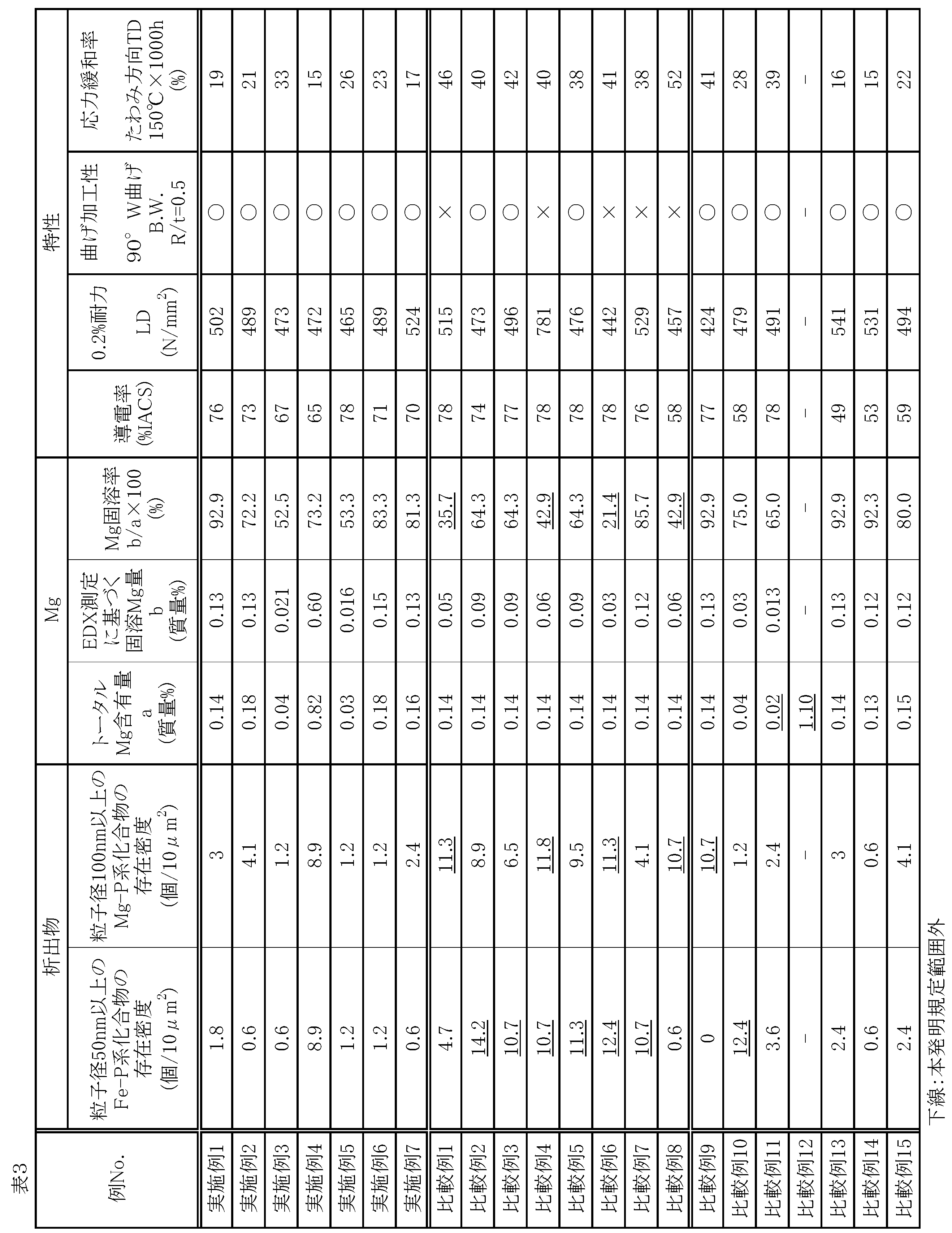
比較例1は、熱間圧延での最終パス温度が低すぎたことにより粗大なMg-P系化合物の存在量が多い熱延板が得られ、後工程においても組織状態の適正化ができなかった。その結果、曲げ加工性と、たわみ方向がTDの耐応力緩和特性が悪かった。
比較例2は、熱間圧延の最終パス温度が高すぎたことにより、最終パス終了後の高温の時期に粗大なFe-P系化合物が多量生成し、後工程においても微細なFe-P系化合物を十分に生成させることができなかった。その結果、たわみ方向がTDの耐応力緩和特性が悪かった。
比較例3は、第1中間焼鈍を省略したことにより、微細なFe-P系化合物を優先的に生成させることができなかった。その結果、たわみ方向がTDの耐応力緩和特性が悪かった。
比較例4は、第1中間焼鈍の昇温速度が遅く、また保持温度が低かったことにより、粗大なMg-P系化合物が多量に生成し、曲げ加工性が悪かった。また、微細なFe-P系化合物の量およびMg固溶率が不十分となり、たわみ方向がTDの耐応力緩和特性が悪かった。
比較例5は、第1中間焼鈍の冷却速度が遅いので、優先的に析出した微細なFe-P系化合物が当該冷却過程で粗大化した。その結果、たわみ方向がTDの耐応力緩和特性が悪かった。
比較例6は、鋳造での凝固後の冷却速度が遅いので鋳片に非常に粗大なFe-P系化合物およびMg-P系化合物が多量に生成し、その後の鋳片加熱温度も低いので、最終的に微細析出物が分散した組織状態が得られなかった。その結果、曲げ加工性と、たわみ方向がTDの耐応力緩和特性が悪かった。
比較例7は、冷間圧延率が低かったことにより第1中間焼鈍の短時間加熱では十分にFe-P系化合物が生成せず、続く第2中間焼鈍を高めの温度で実施することによりFe-P系化合物を生成させた。しかし、焼鈍前の加工率が低いことで再結晶化が不十分となり、また、第2中間焼鈍温度が高いためにFe-P系化合物が成長し、曲げ加工性の低下を招いた。また微細な析出物の分布が不十分となった結果、たわみ方向がTDの耐応力緩和特性も悪かった。
比較例8は、第2中間焼鈍の温度が低すぎたことにより再結晶化が不十分となり、導電性に劣った。また、第2中間焼鈍にてMg-P系化合物の析出および成長がFe-P系化合物の析出よりも優勢となり、曲げ加工性と、たわみ方向がTDの耐応力緩和特性が悪くなった。
比較例9は、FeおよびPが不足するため、微細なFe-P系化合物による強度向上作用と耐応力緩和特性の改善作用が発揮されなかった。
比較例10は、Feが過剰であるため、導電性に劣った。
比較例11は、Mgが本発明の規程をわずかに下回るものである。この場合、固溶Mgの絶対量が少なくなり、たわみ方向がTDの応力緩和率35%以下を目標とする厳しい耐応力緩和特性をクリアすることができなかった。
比較例12は、MgおよびPが過剰であるため、鋳造工程で極めて粗大なMg-P系化合物を多量に生成した。その結果、熱間割れが発生したので、その後の工程の実施を取りやめた。
比較例13、14および15は、それぞれSn、NiおよびZnが過剰であるため、いずれも導電性に劣った。
Claims (4)
- 質量%で、Fe:0.05~2.50%、Mg:0.03~1.00%、P:0.01~0.20%、Sn:0~0.50%、Ni:0~0.30%、Zn:0~0.30%、Si:0~0.10%、Co:0~0.10%、Cr:0~0.10%、B:0~0.10%、Zr:0~0.10%、Ti:0~0.10%、Mn:0~0.10%、V:0~0.10%、残部Cuおよび不可避的不純物からなり、下記(1)式を満たす化学組成を有し、倍率10万倍のTEM観察でのEDX分析により求まるCuマトリクス部分の平均Mg濃度(質量%)を固溶Mg量と呼ぶとき、下記(2)式により定義されるMg固溶率が50%以上であり、粒子径50nm以上のFe-P系化合物の存在密度が10.00個/10μm2以下であり、粒子径100nm以上のMg-P系化合物の存在密度が10.00個/10μm2以下である銅合金板材。
Mg-1.18(P-Fe/3.6)≧0.03 …(1)
Mg固溶率(%)=固溶Mg量(質量%)/トータルMg含有量(質量%)×100 …(2)
ただし、(1)式の元素記号Mg、P、Feの箇所にはそれぞれの元素の含有量を質量%で表した値が代入される。 - 導電率が65%IACS以上であり、圧延方向をLD、圧延方向と板厚方向の両方に対して垂直な方向をTDと呼ぶとき、JIS Z2241に従うLDの0.2%耐力が450N/mm2以上であり、JIS Z3110に従うW曲げ試験において曲げ軸をLD、曲げ半径Rと板厚tの比R/tを0.5とする条件にて割れが観測されない曲げ加工性を有し、片持ち梁方式の応力緩和試験において長手方向がLDに一致し、TDの幅が0.5mmである試験片を用い、たわみ変位の付与方向をTDとする方法でLDの0.2%耐力の80%の負荷応力を加え、150℃で1000時間保持した場合の応力緩和率が35%以下である請求項1に記載の銅合金板材。
- 質量%で、Fe:0.05~2.50%、Mg:0.03~1.00%、P:0.01~0.20%、Sn:0~0.50%、Ni:0~0.30%、Zn:0~0.30%、Si:0~0.10%、Co:0~0.10%、Cr:0~0.10%、B:0~0.10%、Zr:0~0.10%、Ti:0~0.10%、Mn:0~0.10%、V:0~0.10%、残部Cuおよび不可避的不純物からなり、下記(1)式を満たす化学組成の銅合金の溶融物をモールドで凝固させ、凝固後の冷却過程における700~300℃の平均冷却速度を30℃/min以上として鋳片を製造する鋳造工程、
得られた鋳片を850~950℃の範囲に加熱保持する鋳片加熱工程、
前記加熱後の鋳片を最終パス温度が400~700℃となるように熱間圧延した後、400~300℃の平均冷却速度が5℃/sec以上となるように急冷して熱延板とする熱間圧延工程、
前記熱延板を圧延率30%以上で圧延する冷間圧延工程、
600~850℃の範囲にある保持温度T℃まで、300℃からT℃までの平均昇温速度が5℃/sec以上となるように昇温し、T℃で5~300sec保持し、T℃から300℃までの平均冷却速度が5℃/sec以上となるように冷却する第1中間焼鈍工程、
400~590℃の範囲で0.5h以上保持したのち、その保持温度から300℃までの平均冷却速度が20~200℃/hとなるように冷却する第2中間焼鈍工程、
圧延率5~95%で圧延する仕上冷間圧延工程
200~400℃で加熱する低温焼鈍工程、
を有する銅合金板材の製造方法。
Mg-1.18(P-Fe/3.6)≧0.03 …(1)
ただし、(1)式の元素記号Mg、P、Feの箇所にはそれぞれの元素の含有量を質量%で表した値が代入される。 - 請求項1または2に記載の銅合金板材から加工された部品であって、前記銅合金板材の圧延方向と板厚方向の両方に対して垂直な方向(TD)に由来する部品内の方向に負荷応力が付与された状態で使用される通電部品。
Priority Applications (4)
| Application Number | Priority Date | Filing Date | Title |
|---|---|---|---|
| EP14840854.5A EP3040430B1 (en) | 2013-08-30 | 2014-08-26 | Copper alloy sheet material and method for producing same, and current-carrying component |
| US14/912,641 US10844468B2 (en) | 2013-08-30 | 2014-08-26 | Copper alloy sheet material and current-carrying component |
| CN201480047710.8A CN105518164B (zh) | 2013-08-30 | 2014-08-26 | 铜合金板材及其制造方法以及载流部件 |
| KR1020167008117A KR102196590B1 (ko) | 2013-08-30 | 2014-08-26 | 구리 합금 판재 및 이의 제조 방법 및 통전 부품 |
Applications Claiming Priority (2)
| Application Number | Priority Date | Filing Date | Title |
|---|---|---|---|
| JP2013-180162 | 2013-08-30 | ||
| JP2013180162A JP6140032B2 (ja) | 2013-08-30 | 2013-08-30 | 銅合金板材およびその製造方法並びに通電部品 |
Publications (1)
| Publication Number | Publication Date |
|---|---|
| WO2015029986A1 true WO2015029986A1 (ja) | 2015-03-05 |
Family
ID=52586542
Family Applications (1)
| Application Number | Title | Priority Date | Filing Date |
|---|---|---|---|
| PCT/JP2014/072264 Ceased WO2015029986A1 (ja) | 2013-08-30 | 2014-08-26 | 銅合金板材およびその製造方法並びに通電部品 |
Country Status (7)
| Country | Link |
|---|---|
| US (1) | US10844468B2 (ja) |
| EP (1) | EP3040430B1 (ja) |
| JP (1) | JP6140032B2 (ja) |
| KR (1) | KR102196590B1 (ja) |
| CN (1) | CN105518164B (ja) |
| TW (1) | TWI631226B (ja) |
| WO (1) | WO2015029986A1 (ja) |
Families Citing this family (21)
| Publication number | Priority date | Publication date | Assignee | Title |
|---|---|---|---|---|
| JP6155405B2 (ja) * | 2015-04-24 | 2017-06-28 | 古河電気工業株式会社 | 銅合金材料およびその製造方法 |
| WO2016171054A1 (ja) * | 2015-04-24 | 2016-10-27 | 古河電気工業株式会社 | 銅合金板材およびその製造方法 |
| SG11201710361SA (en) | 2015-09-09 | 2018-03-28 | Mitsubishi Materials Corp | Copper alloy for electronic/electrical device, copper alloy plastically worked material for electronic/electrical device, component for electronic/electrical device, terminal, and busbar |
| WO2017170699A1 (ja) * | 2016-03-30 | 2017-10-05 | 三菱マテリアル株式会社 | 電子・電気機器用銅合金、電子・電気機器用銅合金板条材、電子・電気機器用部品、端子、バスバー、及び、リレー用可動片 |
| WO2017170733A1 (ja) * | 2016-03-30 | 2017-10-05 | 三菱マテリアル株式会社 | 電子・電気機器用銅合金、電子・電気機器用銅合金板条材、電子・電気機器用部品、端子、バスバー、及び、リレー用可動片 |
| JP6226098B2 (ja) * | 2016-03-30 | 2017-11-08 | 三菱マテリアル株式会社 | 電子・電気機器用銅合金、電子・電気機器用銅合金板条材、電子・電気機器用部品、端子、バスバー、及び、リレー用可動片 |
| JP6226097B2 (ja) * | 2016-03-30 | 2017-11-08 | 三菱マテリアル株式会社 | 電子・電気機器用銅合金、電子・電気機器用銅合金板条材、電子・電気機器用部品、端子、バスバー、及び、リレー用可動片 |
| WO2018083887A1 (ja) * | 2016-11-07 | 2018-05-11 | 住友電気工業株式会社 | コネクタ端子用線材 |
| CN107400799A (zh) * | 2017-08-07 | 2017-11-28 | 苏州列治埃盟新材料技术转移有限公司 | 一种用于机车电子硬件设备的铜基合金材料及其制备方法 |
| EP3778941A4 (en) | 2018-03-30 | 2021-11-24 | Mitsubishi Materials Corporation | COPPER ALLOY FOR ELECTRONIC / ELECTRIC DEVICE, SHEET / STRIP MATERIAL COPPER ALLOY FOR ELECTRONIC / ELECTRIC DEVICE, ELECTRONIC / ELECTRIC DEVICE COMPONENT, TERMINAL AND OMNIBUS BAR |
| JP6780187B2 (ja) | 2018-03-30 | 2020-11-04 | 三菱マテリアル株式会社 | 電子・電気機器用銅合金、電子・電気機器用銅合金板条材、電子・電気機器用部品、端子、及び、バスバー |
| CN109321779A (zh) * | 2018-10-26 | 2019-02-12 | 浙江星康铜业有限公司 | 一种抗折压的铜板材及其制备方法 |
| CN110904357A (zh) * | 2019-12-17 | 2020-03-24 | 贵溪华泰铜业有限公司 | 一种异型铜管加工方法 |
| CN110938761B (zh) * | 2019-12-31 | 2022-08-09 | 九牧厨卫股份有限公司 | 一种低铅易切削镁黄铜合金及其制备方法 |
| CN113249612A (zh) * | 2021-04-21 | 2021-08-13 | 铁岭富兴铜业有限公司 | 新型触点铜合金及其制备方法 |
| EP4253579B1 (en) * | 2022-03-30 | 2025-01-15 | Dowa Metaltech Co., Ltd | Cu-ti-based copper alloy sheet material, method for producing the same, electric current carrying component, and heat radiation component |
| CN114657410B (zh) * | 2022-04-06 | 2022-09-09 | 中南大学 | 一种高强高导铜铁系合金及其制备方法 |
| CN115323216B (zh) * | 2022-07-28 | 2023-04-04 | 昆明冶金研究院有限公司北京分公司 | 一种高性能铜合金带材及其制备方法 |
| KR20240107676A (ko) | 2022-12-30 | 2024-07-09 | 이구산업 주식회사 | 구리합금 및 그 구리합금의 제조 방법 |
| CN117403095A (zh) * | 2023-11-15 | 2024-01-16 | 铜陵学院 | 一种含稀土y的铜合金材料及其制备方法 |
| CN119663044B (zh) * | 2024-12-25 | 2025-12-09 | 中南大学 | 一种兼顾高强度、高导电及高耐热的Cu-Fe合金材料及其制备方法 |
Citations (9)
| Publication number | Priority date | Publication date | Assignee | Title |
|---|---|---|---|---|
| JPS6167738A (ja) | 1984-08-31 | 1986-04-07 | オリン コーポレーシヨン | 高強度、高導電性銅基合金 |
| JPH10265873A (ja) | 1997-03-26 | 1998-10-06 | Kobe Steel Ltd | 電気電子部品用銅合金及びその製造方法 |
| US6093265A (en) | 1997-07-22 | 2000-07-25 | Olin Corporation | Copper alloy having improved stress relaxation |
| JP2001131657A (ja) * | 1999-08-25 | 2001-05-15 | Kobe Steel Ltd | 電気・電子部品用銅合金 |
| JP2006200036A (ja) | 2004-12-24 | 2006-08-03 | Kobe Steel Ltd | 曲げ加工性及び耐応力緩和特性を備えた銅合金 |
| JP2007039793A (ja) * | 2005-07-07 | 2007-02-15 | Kobe Steel Ltd | 高強度および優れた曲げ加工性を備えた銅合金および銅合金板の製造方法 |
| JP2007177274A (ja) * | 2005-12-27 | 2007-07-12 | Kobe Steel Ltd | 高強度および優れた曲げ加工性を備えた銅合金およびその製造方法 |
| JP2007291518A (ja) | 2006-03-30 | 2007-11-08 | Dowa Metaltech Kk | Cu−Fe−P−Mg系銅合金および製造法並びに通電部品 |
| JP2009275286A (ja) * | 2008-04-16 | 2009-11-26 | Kobe Steel Ltd | 高強度および優れた曲げ加工性を備えた銅合金および銅合金板の製造方法 |
Family Cites Families (11)
| Publication number | Priority date | Publication date | Assignee | Title |
|---|---|---|---|---|
| JPS6092439A (ja) * | 1983-10-25 | 1985-05-24 | Nippon Mining Co Ltd | 耐熱高力高導電性銅合金 |
| JPH0635633B2 (ja) * | 1986-10-29 | 1994-05-11 | 株式会社神戸製鋼所 | 電気および電子部品用銅合金及びその製造方法 |
| US5868877A (en) * | 1997-07-22 | 1999-02-09 | Olin Corporation | Copper alloy having improved stress relaxation |
| JP4959141B2 (ja) * | 2005-02-28 | 2012-06-20 | Dowaホールディングス株式会社 | 高強度銅合金 |
| CN101180412B (zh) * | 2005-07-07 | 2010-05-19 | 株式会社神户制钢所 | 具备高强度和优异的弯曲加工性的铜合金及铜合金板的制造方法 |
| US9034123B2 (en) * | 2007-02-13 | 2015-05-19 | Dowa Metaltech Co., Ltd. | Cu—Ni—Si-based copper alloy sheet material and method of manufacturing same |
| JP5132467B2 (ja) * | 2008-07-30 | 2013-01-30 | 株式会社神戸製鋼所 | 導電率および強度に優れる電気・電子部品用銅合金およびSnめっき銅合金材 |
| CN102257170A (zh) * | 2008-12-19 | 2011-11-23 | 古河电气工业株式会社 | 用于电气电子部件的铜合金材料及其制造方法 |
| JP4672804B1 (ja) * | 2010-05-31 | 2011-04-20 | Jx日鉱日石金属株式会社 | 電子材料用Cu−Co−Si系銅合金及びその製造方法 |
| JP5950499B2 (ja) * | 2011-02-11 | 2016-07-13 | 株式会社神戸製鋼所 | 電気・電子部品用銅合金及びSnめっき付き銅合金材 |
| JP5834528B2 (ja) * | 2011-06-22 | 2015-12-24 | 三菱マテリアル株式会社 | 電気・電子機器用銅合金 |
-
2013
- 2013-08-30 JP JP2013180162A patent/JP6140032B2/ja active Active
-
2014
- 2014-08-26 EP EP14840854.5A patent/EP3040430B1/en active Active
- 2014-08-26 WO PCT/JP2014/072264 patent/WO2015029986A1/ja not_active Ceased
- 2014-08-26 KR KR1020167008117A patent/KR102196590B1/ko active Active
- 2014-08-26 CN CN201480047710.8A patent/CN105518164B/zh active Active
- 2014-08-26 US US14/912,641 patent/US10844468B2/en active Active
- 2014-08-28 TW TW103129655A patent/TWI631226B/zh active
Patent Citations (9)
| Publication number | Priority date | Publication date | Assignee | Title |
|---|---|---|---|---|
| JPS6167738A (ja) | 1984-08-31 | 1986-04-07 | オリン コーポレーシヨン | 高強度、高導電性銅基合金 |
| JPH10265873A (ja) | 1997-03-26 | 1998-10-06 | Kobe Steel Ltd | 電気電子部品用銅合金及びその製造方法 |
| US6093265A (en) | 1997-07-22 | 2000-07-25 | Olin Corporation | Copper alloy having improved stress relaxation |
| JP2001131657A (ja) * | 1999-08-25 | 2001-05-15 | Kobe Steel Ltd | 電気・電子部品用銅合金 |
| JP2006200036A (ja) | 2004-12-24 | 2006-08-03 | Kobe Steel Ltd | 曲げ加工性及び耐応力緩和特性を備えた銅合金 |
| JP2007039793A (ja) * | 2005-07-07 | 2007-02-15 | Kobe Steel Ltd | 高強度および優れた曲げ加工性を備えた銅合金および銅合金板の製造方法 |
| JP2007177274A (ja) * | 2005-12-27 | 2007-07-12 | Kobe Steel Ltd | 高強度および優れた曲げ加工性を備えた銅合金およびその製造方法 |
| JP2007291518A (ja) | 2006-03-30 | 2007-11-08 | Dowa Metaltech Kk | Cu−Fe−P−Mg系銅合金および製造法並びに通電部品 |
| JP2009275286A (ja) * | 2008-04-16 | 2009-11-26 | Kobe Steel Ltd | 高強度および優れた曲げ加工性を備えた銅合金および銅合金板の製造方法 |
Also Published As
| Publication number | Publication date |
|---|---|
| TWI631226B (zh) | 2018-08-01 |
| EP3040430A4 (en) | 2017-05-24 |
| US10844468B2 (en) | 2020-11-24 |
| JP6140032B2 (ja) | 2017-05-31 |
| EP3040430B1 (en) | 2018-10-10 |
| CN105518164B (zh) | 2018-07-27 |
| TW201518517A (zh) | 2015-05-16 |
| KR20160051818A (ko) | 2016-05-11 |
| EP3040430A1 (en) | 2016-07-06 |
| CN105518164A (zh) | 2016-04-20 |
| KR102196590B1 (ko) | 2020-12-31 |
| US20160201179A1 (en) | 2016-07-14 |
| JP2015048503A (ja) | 2015-03-16 |
Similar Documents
| Publication | Publication Date | Title |
|---|---|---|
| JP6140032B2 (ja) | 銅合金板材およびその製造方法並びに通電部品 | |
| JP6039999B2 (ja) | Cu−Ni−Co−Si系銅合金板材およびその製造法 | |
| KR20150116825A (ko) | 고강도 Cu-Ni-Co-Si계 구리 합금 판재 및 이의 제조법 및 통전 부품 | |
| WO2010126046A1 (ja) | 導電性と曲げ性を改善したCu-Ni-Si-Mg系合金 | |
| JP6440476B2 (ja) | アルミニウム合金線材、アルミニウム合金撚線、被覆電線およびワイヤーハーネス、ならびにアルミニウム合金線材の製造方法 | |
| CN108026612A (zh) | 铜合金板材及其制造方法 | |
| JP2013044038A (ja) | アルミニウム合金導体 | |
| WO2012026488A1 (ja) | 電子材料用Cu-Co-Si系合金 | |
| JP5802150B2 (ja) | 銅合金 | |
| WO2019189534A1 (ja) | 電子・電気機器用銅合金、電子・電気機器用銅合金板条材、電子・電気機器用部品、端子、及び、バスバー | |
| JP2011012321A (ja) | 銅合金材およびその製造方法 | |
| JP6389414B2 (ja) | 銅合金板材の製造方法 | |
| WO2014109211A1 (ja) | 電子・電気機器用銅合金、電子・電気機器用部品及び端子 | |
| JP2009203510A (ja) | 高強度および高導電率を兼備した銅合金 | |
| JP4959141B2 (ja) | 高強度銅合金 | |
| JP2017039959A (ja) | Cu−Ti系銅合金板材およびその製造方法並びに通電部品 | |
| WO2016047175A1 (ja) | 銅合金板及び銅合金板の製造方法 | |
| KR20160133371A (ko) | 내열성이 우수한 구리 합금 | |
| KR20060130183A (ko) | 구리합금 | |
| JP5952726B2 (ja) | 銅合金 | |
| JP5879464B1 (ja) | 銅合金板及び銅合金板の製造方法 | |
| JP5748945B2 (ja) | 銅合金材の製造方法とそれにより得られる銅合金材 | |
| JP2012229467A (ja) | 電子材料用Cu−Ni−Si系銅合金 | |
| JP5638357B2 (ja) | 電気・電子部品用銅合金およびその製造方法 | |
| JP2011190508A (ja) | 電子部品用チタン銅及びこれを用いた電子部品 |
Legal Events
| Date | Code | Title | Description |
|---|---|---|---|
| 121 | Ep: the epo has been informed by wipo that ep was designated in this application |
Ref document number: 14840854 Country of ref document: EP Kind code of ref document: A1 |
|
| WWE | Wipo information: entry into national phase |
Ref document number: 14912641 Country of ref document: US |
|
| REEP | Request for entry into the european phase |
Ref document number: 2014840854 Country of ref document: EP |
|
| WWE | Wipo information: entry into national phase |
Ref document number: 2014840854 Country of ref document: EP |
|
| NENP | Non-entry into the national phase |
Ref country code: DE |
|
| ENP | Entry into the national phase |
Ref document number: 20167008117 Country of ref document: KR Kind code of ref document: A |