WO2015032324A1 - 混合动力汽车的控制系统和控制方法 - Google Patents
混合动力汽车的控制系统和控制方法 Download PDFInfo
- Publication number
- WO2015032324A1 WO2015032324A1 PCT/CN2014/085830 CN2014085830W WO2015032324A1 WO 2015032324 A1 WO2015032324 A1 WO 2015032324A1 CN 2014085830 W CN2014085830 W CN 2014085830W WO 2015032324 A1 WO2015032324 A1 WO 2015032324A1
- Authority
- WO
- WIPO (PCT)
- Prior art keywords
- power
- mode
- hybrid
- vehicle
- engine
- Prior art date
- Legal status (The legal status is an assumption and is not a legal conclusion. Google has not performed a legal analysis and makes no representation as to the accuracy of the status listed.)
- Ceased
Links
Classifications
-
- B—PERFORMING OPERATIONS; TRANSPORTING
- B60—VEHICLES IN GENERAL
- B60W—CONJOINT CONTROL OF VEHICLE SUB-UNITS OF DIFFERENT TYPE OR DIFFERENT FUNCTION; CONTROL SYSTEMS SPECIALLY ADAPTED FOR HYBRID VEHICLES; ROAD VEHICLE DRIVE CONTROL SYSTEMS FOR PURPOSES NOT RELATED TO THE CONTROL OF A PARTICULAR SUB-UNIT
- B60W10/00—Conjoint control of vehicle sub-units of different type or different function
- B60W10/04—Conjoint control of vehicle sub-units of different type or different function including control of propulsion units
- B60W10/06—Conjoint control of vehicle sub-units of different type or different function including control of propulsion units including control of combustion engines
-
- B—PERFORMING OPERATIONS; TRANSPORTING
- B60—VEHICLES IN GENERAL
- B60W—CONJOINT CONTROL OF VEHICLE SUB-UNITS OF DIFFERENT TYPE OR DIFFERENT FUNCTION; CONTROL SYSTEMS SPECIALLY ADAPTED FOR HYBRID VEHICLES; ROAD VEHICLE DRIVE CONTROL SYSTEMS FOR PURPOSES NOT RELATED TO THE CONTROL OF A PARTICULAR SUB-UNIT
- B60W20/00—Control systems specially adapted for hybrid vehicles
- B60W20/10—Controlling the power contribution of each of the prime movers to meet required power demand
- B60W20/13—Controlling the power contribution of each of the prime movers to meet required power demand in order to stay within battery power input or output limits; in order to prevent overcharging or battery depletion
-
- B—PERFORMING OPERATIONS; TRANSPORTING
- B60—VEHICLES IN GENERAL
- B60W—CONJOINT CONTROL OF VEHICLE SUB-UNITS OF DIFFERENT TYPE OR DIFFERENT FUNCTION; CONTROL SYSTEMS SPECIALLY ADAPTED FOR HYBRID VEHICLES; ROAD VEHICLE DRIVE CONTROL SYSTEMS FOR PURPOSES NOT RELATED TO THE CONTROL OF A PARTICULAR SUB-UNIT
- B60W10/00—Conjoint control of vehicle sub-units of different type or different function
- B60W10/04—Conjoint control of vehicle sub-units of different type or different function including control of propulsion units
- B60W10/08—Conjoint control of vehicle sub-units of different type or different function including control of propulsion units including control of electric propulsion units, e.g. motors or generators
-
- B—PERFORMING OPERATIONS; TRANSPORTING
- B60—VEHICLES IN GENERAL
- B60W—CONJOINT CONTROL OF VEHICLE SUB-UNITS OF DIFFERENT TYPE OR DIFFERENT FUNCTION; CONTROL SYSTEMS SPECIALLY ADAPTED FOR HYBRID VEHICLES; ROAD VEHICLE DRIVE CONTROL SYSTEMS FOR PURPOSES NOT RELATED TO THE CONTROL OF A PARTICULAR SUB-UNIT
- B60W10/00—Conjoint control of vehicle sub-units of different type or different function
- B60W10/24—Conjoint control of vehicle sub-units of different type or different function including control of energy storage means
- B60W10/26—Conjoint control of vehicle sub-units of different type or different function including control of energy storage means for electrical energy, e.g. batteries or capacitors
-
- B—PERFORMING OPERATIONS; TRANSPORTING
- B60—VEHICLES IN GENERAL
- B60W—CONJOINT CONTROL OF VEHICLE SUB-UNITS OF DIFFERENT TYPE OR DIFFERENT FUNCTION; CONTROL SYSTEMS SPECIALLY ADAPTED FOR HYBRID VEHICLES; ROAD VEHICLE DRIVE CONTROL SYSTEMS FOR PURPOSES NOT RELATED TO THE CONTROL OF A PARTICULAR SUB-UNIT
- B60W20/00—Control systems specially adapted for hybrid vehicles
- B60W20/10—Controlling the power contribution of each of the prime movers to meet required power demand
-
- B—PERFORMING OPERATIONS; TRANSPORTING
- B60—VEHICLES IN GENERAL
- B60W—CONJOINT CONTROL OF VEHICLE SUB-UNITS OF DIFFERENT TYPE OR DIFFERENT FUNCTION; CONTROL SYSTEMS SPECIALLY ADAPTED FOR HYBRID VEHICLES; ROAD VEHICLE DRIVE CONTROL SYSTEMS FOR PURPOSES NOT RELATED TO THE CONTROL OF A PARTICULAR SUB-UNIT
- B60W20/00—Control systems specially adapted for hybrid vehicles
- B60W20/10—Controlling the power contribution of each of the prime movers to meet required power demand
- B60W20/15—Control strategies specially adapted for achieving a particular effect
-
- B—PERFORMING OPERATIONS; TRANSPORTING
- B60—VEHICLES IN GENERAL
- B60W—CONJOINT CONTROL OF VEHICLE SUB-UNITS OF DIFFERENT TYPE OR DIFFERENT FUNCTION; CONTROL SYSTEMS SPECIALLY ADAPTED FOR HYBRID VEHICLES; ROAD VEHICLE DRIVE CONTROL SYSTEMS FOR PURPOSES NOT RELATED TO THE CONTROL OF A PARTICULAR SUB-UNIT
- B60W20/00—Control systems specially adapted for hybrid vehicles
- B60W20/40—Controlling the engagement or disengagement of prime movers, e.g. for transition between prime movers
-
- B—PERFORMING OPERATIONS; TRANSPORTING
- B60—VEHICLES IN GENERAL
- B60W—CONJOINT CONTROL OF VEHICLE SUB-UNITS OF DIFFERENT TYPE OR DIFFERENT FUNCTION; CONTROL SYSTEMS SPECIALLY ADAPTED FOR HYBRID VEHICLES; ROAD VEHICLE DRIVE CONTROL SYSTEMS FOR PURPOSES NOT RELATED TO THE CONTROL OF A PARTICULAR SUB-UNIT
- B60W30/00—Purposes of road vehicle drive control systems not related to the control of a particular sub-unit, e.g. of systems using conjoint control of vehicle sub-units
- B60W30/18—Propelling the vehicle
- B60W30/182—Selecting between different operative modes, e.g. comfort and performance modes
-
- B—PERFORMING OPERATIONS; TRANSPORTING
- B60—VEHICLES IN GENERAL
- B60W—CONJOINT CONTROL OF VEHICLE SUB-UNITS OF DIFFERENT TYPE OR DIFFERENT FUNCTION; CONTROL SYSTEMS SPECIALLY ADAPTED FOR HYBRID VEHICLES; ROAD VEHICLE DRIVE CONTROL SYSTEMS FOR PURPOSES NOT RELATED TO THE CONTROL OF A PARTICULAR SUB-UNIT
- B60W30/00—Purposes of road vehicle drive control systems not related to the control of a particular sub-unit, e.g. of systems using conjoint control of vehicle sub-units
- B60W30/18—Propelling the vehicle
- B60W30/188—Controlling power parameters of the driveline, e.g. determining the required power
- B60W30/1882—Controlling power parameters of the driveline, e.g. determining the required power characterised by the working point of the engine, e.g. by using engine output chart
-
- B—PERFORMING OPERATIONS; TRANSPORTING
- B60—VEHICLES IN GENERAL
- B60W—CONJOINT CONTROL OF VEHICLE SUB-UNITS OF DIFFERENT TYPE OR DIFFERENT FUNCTION; CONTROL SYSTEMS SPECIALLY ADAPTED FOR HYBRID VEHICLES; ROAD VEHICLE DRIVE CONTROL SYSTEMS FOR PURPOSES NOT RELATED TO THE CONTROL OF A PARTICULAR SUB-UNIT
- B60W2510/00—Input parameters relating to a particular sub-units
- B60W2510/24—Energy storage means
- B60W2510/242—Energy storage means for electrical energy
- B60W2510/244—Charge state
-
- B—PERFORMING OPERATIONS; TRANSPORTING
- B60—VEHICLES IN GENERAL
- B60W—CONJOINT CONTROL OF VEHICLE SUB-UNITS OF DIFFERENT TYPE OR DIFFERENT FUNCTION; CONTROL SYSTEMS SPECIALLY ADAPTED FOR HYBRID VEHICLES; ROAD VEHICLE DRIVE CONTROL SYSTEMS FOR PURPOSES NOT RELATED TO THE CONTROL OF A PARTICULAR SUB-UNIT
- B60W2710/00—Output or target parameters relating to a particular sub-units
- B60W2710/06—Combustion engines, Gas turbines
- B60W2710/0666—Engine torque
-
- B—PERFORMING OPERATIONS; TRANSPORTING
- B60—VEHICLES IN GENERAL
- B60W—CONJOINT CONTROL OF VEHICLE SUB-UNITS OF DIFFERENT TYPE OR DIFFERENT FUNCTION; CONTROL SYSTEMS SPECIALLY ADAPTED FOR HYBRID VEHICLES; ROAD VEHICLE DRIVE CONTROL SYSTEMS FOR PURPOSES NOT RELATED TO THE CONTROL OF A PARTICULAR SUB-UNIT
- B60W2710/00—Output or target parameters relating to a particular sub-units
- B60W2710/06—Combustion engines, Gas turbines
- B60W2710/0677—Engine power
-
- B—PERFORMING OPERATIONS; TRANSPORTING
- B60—VEHICLES IN GENERAL
- B60W—CONJOINT CONTROL OF VEHICLE SUB-UNITS OF DIFFERENT TYPE OR DIFFERENT FUNCTION; CONTROL SYSTEMS SPECIALLY ADAPTED FOR HYBRID VEHICLES; ROAD VEHICLE DRIVE CONTROL SYSTEMS FOR PURPOSES NOT RELATED TO THE CONTROL OF A PARTICULAR SUB-UNIT
- B60W2710/00—Output or target parameters relating to a particular sub-units
- B60W2710/08—Electric propulsion units
- B60W2710/086—Power
-
- B—PERFORMING OPERATIONS; TRANSPORTING
- B60—VEHICLES IN GENERAL
- B60W—CONJOINT CONTROL OF VEHICLE SUB-UNITS OF DIFFERENT TYPE OR DIFFERENT FUNCTION; CONTROL SYSTEMS SPECIALLY ADAPTED FOR HYBRID VEHICLES; ROAD VEHICLE DRIVE CONTROL SYSTEMS FOR PURPOSES NOT RELATED TO THE CONTROL OF A PARTICULAR SUB-UNIT
- B60W2710/00—Output or target parameters relating to a particular sub-units
- B60W2710/24—Energy storage means
- B60W2710/242—Energy storage means for electrical energy
- B60W2710/244—Charge state
-
- Y—GENERAL TAGGING OF NEW TECHNOLOGICAL DEVELOPMENTS; GENERAL TAGGING OF CROSS-SECTIONAL TECHNOLOGIES SPANNING OVER SEVERAL SECTIONS OF THE IPC; TECHNICAL SUBJECTS COVERED BY FORMER USPC CROSS-REFERENCE ART COLLECTIONS [XRACs] AND DIGESTS
- Y02—TECHNOLOGIES OR APPLICATIONS FOR MITIGATION OR ADAPTATION AGAINST CLIMATE CHANGE
- Y02T—CLIMATE CHANGE MITIGATION TECHNOLOGIES RELATED TO TRANSPORTATION
- Y02T10/00—Road transport of goods or passengers
- Y02T10/10—Internal combustion engine [ICE] based vehicles
- Y02T10/40—Engine management systems
-
- Y—GENERAL TAGGING OF NEW TECHNOLOGICAL DEVELOPMENTS; GENERAL TAGGING OF CROSS-SECTIONAL TECHNOLOGIES SPANNING OVER SEVERAL SECTIONS OF THE IPC; TECHNICAL SUBJECTS COVERED BY FORMER USPC CROSS-REFERENCE ART COLLECTIONS [XRACs] AND DIGESTS
- Y02—TECHNOLOGIES OR APPLICATIONS FOR MITIGATION OR ADAPTATION AGAINST CLIMATE CHANGE
- Y02T—CLIMATE CHANGE MITIGATION TECHNOLOGIES RELATED TO TRANSPORTATION
- Y02T10/00—Road transport of goods or passengers
- Y02T10/60—Other road transportation technologies with climate change mitigation effect
- Y02T10/62—Hybrid vehicles
-
- Y—GENERAL TAGGING OF NEW TECHNOLOGICAL DEVELOPMENTS; GENERAL TAGGING OF CROSS-SECTIONAL TECHNOLOGIES SPANNING OVER SEVERAL SECTIONS OF THE IPC; TECHNICAL SUBJECTS COVERED BY FORMER USPC CROSS-REFERENCE ART COLLECTIONS [XRACs] AND DIGESTS
- Y02—TECHNOLOGIES OR APPLICATIONS FOR MITIGATION OR ADAPTATION AGAINST CLIMATE CHANGE
- Y02T—CLIMATE CHANGE MITIGATION TECHNOLOGIES RELATED TO TRANSPORTATION
- Y02T10/00—Road transport of goods or passengers
- Y02T10/80—Technologies aiming to reduce greenhouse gasses emissions common to all road transportation technologies
- Y02T10/84—Data processing systems or methods, management, administration
-
- Y—GENERAL TAGGING OF NEW TECHNOLOGICAL DEVELOPMENTS; GENERAL TAGGING OF CROSS-SECTIONAL TECHNOLOGIES SPANNING OVER SEVERAL SECTIONS OF THE IPC; TECHNICAL SUBJECTS COVERED BY FORMER USPC CROSS-REFERENCE ART COLLECTIONS [XRACs] AND DIGESTS
- Y10—TECHNICAL SUBJECTS COVERED BY FORMER USPC
- Y10S—TECHNICAL SUBJECTS COVERED BY FORMER USPC CROSS-REFERENCE ART COLLECTIONS [XRACs] AND DIGESTS
- Y10S903/00—Hybrid electric vehicles, HEVS
- Y10S903/902—Prime movers comprising electrical and internal combustion motors
- Y10S903/903—Prime movers comprising electrical and internal combustion motors having energy storing means, e.g. battery, capacitor
- Y10S903/93—Conjoint control of different elements
Definitions
- a control system for a hybrid vehicle includes: a transmission device for driving a wheel of a hybrid vehicle; an engine power subsystem, the engine power a subsystem connected to the transmission; a motor power subsystem, the motor power subsystem being coupled to the transmission; and a controller controlling the engine power subsystem and the motor power subsystem to control
- the hybrid vehicle enters a corresponding working mode, wherein the working mode package a pure electric mode and a hybrid mode, and when the SOC of the power battery in the motor power subsystem is less than or equal to a first power threshold, the maximum allowable discharge power of the power battery is less than or equal to a first power threshold, or the hybrid
- the controller controls the hybrid vehicle to switch from the pure electric mode to the hybrid mode when the current slope signal detected by the vehicle is greater than or equal to the upper slope threshold.
- FIG. 5 is a flow chart showing a control method of a hybrid vehicle when the hybrid vehicle is in a hybrid economy mode according to still another embodiment of the present invention.
- FIG. 6 is a flow chart showing a control method when a hybrid vehicle is operated in an economical manner when the hybrid vehicle is in a hybrid economy mode according to still another embodiment of the present invention
- FIG. 11 is a flow chart of a control method of a hybrid vehicle according to an embodiment of the present invention. detailed description
- the terms “installation”, “connected”, and “connected” are to be understood broadly, and may be, for example, mechanical or electrical, or both.
- the internal communication of the components may be directly connected or indirectly connected through an intermediate medium.
- the specific meanings of the above terms may be understood according to specific situations.
- FIG. 1A is a block schematic diagram of a control system of a hybrid vehicle in accordance with an embodiment of the invention.
- the control system of the hybrid vehicle includes a transmission 10, an engine power subsystem 20, a motor power subsystem 30, and a controller 40.
- the transmission device 10 is used to drive the wheels 2a and 2b of the hybrid vehicle, the engine power subsystem 20 is connected to the transmission device 10, and the motor power subsystem 30 is connected to the transmission device 10.
- the controller 40 controls the hybrid vehicle to enter a corresponding operating mode by controlling the engine power subsystem 20 and the motor power subsystem 30, wherein the operating modes include a pure electric mode, that is, an EV mode, and a hybrid mode, that is, an HEV mode. And when the SOC of the power battery in the motor power subsystem is less than or equal to the first power threshold, the maximum allowable discharge power of the power battery is less than or equal to the first power threshold, or the current slope signal detected by the hybrid vehicle is greater than or equal to the slope.
- the controller controls the hybrid vehicle to switch from the pure electric mode to the hybrid mode when an upper threshold is reached.
- the hybrid vehicle is a pluggable dual-mode hybrid vehicle, wherein the engine 3 is a high-efficiency turbocharged direct-injection engine capable of outputting driving power, and the transmission 4 is capable of transmitting
- the engine 3 outputs a dual clutch transmission
- the power battery 7 is connected to the power electronic unit inverter 8 through a DC bus
- the inverter 8 is connected to the motor 5 through an AC three-phase line
- the electric power and the fuel power are coupled at the transmission 10 and It is transmitted to the wheels 2a and 2b.
- the user can select the working mode of the hybrid car through the EV mode selection button, the HEV mode selection button and the operation mode selection knob button.
- the power battery is used to power the motor to drive the vehicle without triggering the mode switching condition, and Keep the engine out of operation.
- the HEV button is manually pressed, the working mode of the hybrid vehicle is switched to the HEV-eco mode; when the button is manually rotated to the Sport, the working mode of the hybrid vehicle is switched to the EV-s mode; when the mode button is not manually input, If the power storage S0C of the power battery is less than or equal to the S0C lower limit threshold, for example, 20%, or the maximum allowable discharge power of the power battery is less than or equal to the lower power threshold, for example, 12 KW, or the gradient signal is greater than the upper gradient threshold, for example, 15%, the controller 40 automatically controls the hybrid.
- the controller 40 controls the hybrid vehicle to switch to the hybrid motion mode.
- the controller controls the hybrid vehicle to operate in an economical manner; if the current gradient signal detected by the hybrid vehicle is less than or equal to a lower gradient threshold, for example, 5% and the SOC of the power battery is less than or equal to A power threshold is, for example, 20%, or the current gradient signal detected by the hybrid vehicle is less than or equal to a lower gradient threshold, for example, 5%, and the maximum allowable discharge power of the power battery is less than or equal to a first power threshold, for example, 12 KW, and the controller controls the hybrid vehicle to be low.
- the mode runs, where the second power threshold is greater than the first power threshold, and the second power threshold is greater than the first power threshold.
- the low-power mode means that the engine drives the motor to generate electricity quickly, thereby Get rid of the low-power state, so that the motor has the ability to adjust the engine working range, thus ensuring the economy of the vehicle.
- a second speed threshold for example, 15 km/h
- the controller controls the hybrid vehicle to perform pure electric driving. .
- the preset torque upper limit curve of the engine and the preset torque lower limit curve of the engine are as shown in FIG. 7, when the vehicle total torque demand of the hybrid vehicle is between the preset torque limit curve of the engine and the preset of the engine.
- the torque lower limit curve is between, the relationship between the power generation of the motor and the SOC value of the power battery is as shown in Fig. 8.
- the economic strategy requires that the current speed of the hybrid vehicle is less than or equal to 15km/h, pure electric drive hybrid
- the engine participates in the drive until the vehicle speed drops to 15km/h, and then resumes to the pure electric drive. If the motor alarm at this stage causes the drive capacity to be insufficient, the engine is started.
- the low-power strategy cancels the low-speed pure electric and increases the start-stop function of the P-block engine. Among them, the low-power strategy and the economic strategy are consistent in the control method after the engine is started, and the upper limit curve and the lower limit curve of the output torque of the engine are set, as shown in Fig.
- the engine is output according to the vehicle demand; between the upper and lower limit curves, the motor mainly participates in power generation, and the power generation has a certain function relationship with the current SOC value, as shown in Figure 8, but the total output torque of the engine does not exceed the upper limit curve.
- the controller determines that the SOC of the power battery is greater than When the second power threshold is equal to, for example, 30%, and the current vehicle speed of the hybrid vehicle is less than or equal to the first speed threshold, for example, 150 km/h, the controller controls the hybrid vehicle to switch to the pure electric motion mode.
- the EV button when driving the hybrid vehicle traveling in the HEV-s mode, when the EV button is manually pressed, only when the power source S OC of the power battery is greater than or equal to the upper SOC threshold.
- the first speed threshold for example, 150km/h
- the working mode of the hybrid vehicle is allowed. Switch to EV-s mode, otherwise it will not switch the working mode; when the button is manually rotated to eco, the working mode of the hybrid car switches to HEV-eco mode; when the mode button has no manual input, the working mode of the hybrid car remains.
- the HEV-s mode is unchanged.
- the HEV-s mode strategy is similar to the HEV-eco low-power strategy.
- the low-speed pure electric motor is cancelled, and the P-block engine start-stop function is added, the motor power limit is canceled, and the engine torque is cancelled.
- the lower limit, the engine and motor can be peak output, this mode can get the best dynamic performance.
- the most economical area in the pure electric mode means that as the power output of the power battery increases, the working efficiency of the power battery decreases correspondingly, so that the vehicle power is satisfied (operational performance and Under the premise of acceleration performance, the power battery is preferably operated with a lower discharge power.
- the power battery In the most economical mode, in the hybrid mode, as the power output of the power battery increases, the operating efficiency of the power battery decreases accordingly. Therefore, under the premise of satisfying the vehicle dynamic performance (operating performance and acceleration performance), the power battery is preferred. Low discharge power is used for operation.
- the most economical area of the engine is determined by the torque and speed of the engine. As shown in Figure 7, the abscissa indicates the engine speed and the ordinate indicates the engine torque.
- the engine power subsystem and the motor power subsystem are connected in parallel, and the power system of the existing hybrid vehicle is connected in series, which can effectively improve the energy utilization rate.
- the parallel structure is relatively simple, avoiding the complicated ECVT matching of the hybrid mode, and reducing the risk of unevenness caused by poor matching, so the economic performance is greatly improved under the premise of ensuring the dynamic performance of the whole vehicle.
- it ensures the power and driving range of the pure electric operation of the whole vehicle, and avoids the long-term high-power electricity to improve the power efficiency under the premise of meeting the power demand of the whole vehicle.
- the engine is prevented from starting and stopping frequently, thereby improving the life of the starter, reducing driving noise and improving driving comfort.
- the hybrid vehicle comprises a transmission device, an engine power subsystem and a motor power subsystem, and the transmission device is respectively connected to the engine power subsystem and the motor power subsystem.
- the control method of the hybrid vehicle includes the following steps: 51.
- the hybrid power vehicle is controlled to enter a corresponding working mode by controlling the engine power subsystem and the motor power subsystem, wherein the working modes include a pure electric mode and a hybrid mode.
- step S103 If the three conditions are not satisfied in step S103, the automatic switching of the HEV-eco mode is not performed, and the hybrid vehicle maintains the EV-eco mode operation.
- the motor When the hybrid car is running in the EV-eco mode, the motor is made without manual or automatic mode switching. Driven for a single power source.
- the main purpose of this working mode is to save power while meeting the power demand of the whole vehicle.
- the maximum output power of the motor is limited to Pm max, for example 70KW, and at the same time
- the climbing performance of the whole vehicle therefore, does not limit the maximum output torque of the motor. That is to say, when the hybrid vehicle is in the pure electric economy mode, the hybrid vehicle is controlled to operate at a limited power.
- the hybrid vehicle is automatically switched to the HEV-eco mode by judging the SOC value of the power battery, the maximum allowable discharge power of the power battery, and the gradient value.
- the strategy ensures the ability of the vehicle to continue to operate normally, avoiding the possibility of degrading power performance due to certain factors.
- the control method of the above-mentioned hybrid vehicle in the EV-eco mode ensures that the motor battery always operates in the high-efficiency zone under the premise of satisfying the vehicle power, thereby realizing the long-lasting pure electric vehicle mileage, low operating cost, and emission of the hybrid vehicle. dramatically drop.
- the working mode of the hybrid vehicle is automatically switched to the HEV-s mode, that is, if the SOC of the power battery is less than or equal to the first power threshold, for example, 20%, or the power battery
- the maximum allowable discharge power is less than or equal to the first power threshold, for example, 12 KW, or the hybrid vehicle is automatically switched to the hybrid motion mode when the current gradient signal detected by the hybrid vehicle is greater than or equal to the upper gradient threshold, for example, 15%.
- step S203 If the three conditions are not satisfied in step S203, the automatic switching of the HEV-s mode is not performed, and the hybrid vehicle maintains the EV-s mode operation.
- the motor When the hybrid vehicle is driven in the EV-s mode, the motor is always driven as a single power source without manual or automatic mode switching. This working mode does not limit the maximum output torque and power of the motor, and can obtain the maximum capacity of the motor to drive, to meet the higher power requirements of the user in the EV mode (such as overtaking acceleration, rapid climbing, etc.).
- step S305 comparing the current vehicle speed with a set vehicle speed threshold V max, for example, 150 km/h, that is, a maximum vehicle speed that allows the HEV mode to switch to the EV mode, determining whether v V max is satisfied, and if yes, proceeding to step S304; if not, then Go to step S305.
- V max for example, 150 km/h
- Hybrid cars operate in HEV-eco mode.
- the hybrid vehicle After receiving the Sport mode button switching operation, the hybrid vehicle is controlled to switch to the HEV-s mode and the corresponding power system control strategy is executed.
- the hybrid vehicle when the hybrid vehicle is in the hybrid economy mode, if the current gradient signal detected by the hybrid vehicle is less than or equal to the lower gradient threshold, for example, 5%, and the SOC of the power battery is greater than or equal to the second power threshold, for example, 30%, the power battery The maximum allowable discharge power is greater than or equal to a second power threshold, such as 30 kW, and the controller controls the hybrid vehicle to operate in an economical manner.
- the lower gradient threshold for example, 5%
- the SOC of the power battery is greater than or equal to the second power threshold, for example, 30%
- the maximum allowable discharge power is greater than or equal to a second power threshold, such as 30 kW, and the controller controls the hybrid vehicle to operate in an economical manner.
- the hybrid vehicle when the hybrid vehicle is in the hybrid economy mode, if the current gradient signal detected by the hybrid vehicle is less than or equal to the lower gradient threshold, for example, 5% and the SOC of the power battery is less than or equal to the first power threshold, for example, 20%, or hybrid
- the current slope signal detected by the automobile is less than or equal to the lower limit threshold value, for example, 5%
- the maximum allowable discharge power of the power battery is less than or equal to the first power threshold, for example, 12 KW
- the controller controls the hybrid vehicle to operate in a low power mode, wherein the second power threshold is greater than The first power threshold, the second power threshold being greater than the first power threshold.
- control method of the hybrid vehicle when the hybrid vehicle is operated in an economical manner includes the following steps:
- step S404 When it is determined that the torque demand of the entire vehicle is greater than the torque upper limit curve as shown in Fig. 7, the process proceeds to step S404.
- step S406 Determine whether the power system of the hybrid vehicle is faulty. If yes, go to step S406; if no, go to step S405.
- the engine is controlled to output according to the upper torque limit curve, and the remaining torque demand is supplemented by the motor, that is, when the hybrid vehicle is operated in an economical manner, if the speed of the hybrid vehicle is greater than or equal to a third speed threshold, for example, 30 km. /h, wherein, when the vehicle torque demand of the hybrid vehicle is greater than the preset torque upper limit curve of the engine, the controller controls the engine to perform torque output with a preset torque upper limit curve, and controls the motor to perform torque compensation.
- a third speed threshold for example, 30 km. /h
- step S410 determines whether the power system of the hybrid vehicle is faulty, if yes, executing step S410; if not, executing step S409.
- step S418 determines whether the power system of the hybrid vehicle is faulty, if yes, executing step S418; if not, executing step S417.
- the power system is controlled according to the original strategy workflow. That is, if the original motor is driven separately, it will still operate according to this mode. If the original motor assists the engine to drive or generate electricity, it will still operate in this way.
- step S422 determines whether the power system of the hybrid vehicle is faulty, if yes, executing step S422; if not, executing step S421.
- Hybrid vehicles are purely electric, that is, hybrid electric vehicles operate purely electric.
- step S506 Determine whether the power system of the hybrid vehicle is faulty. If yes, go to step S506; if no, go to step S505.
- the engine is output according to the upper torque curve, and the residual torque demand is supplemented by the motor. That is, when the hybrid vehicle is running in a low-power mode, if the current position of the hybrid vehicle is at In the case of non-P gear, wherein when the vehicle torque demand of the hybrid vehicle is greater than the preset torque upper limit curve of the engine, the controller controls the engine to perform torque output with a preset torque upper limit curve, and controls the motor to perform torque compensation.
- step S508 when it is determined that the vehicle torque demand is smaller than the torque lower limit curve as shown in FIG. 7, the process proceeds to step S508.
- step S510 determines whether the power system of the hybrid vehicle is faulty, if yes, executing step S510; if not, executing step S509.
- step S512 it is determined that the torque requirement of the whole vehicle is between the upper and lower torque curves shown in FIG. 7, and the process proceeds to step S512.
- step S514 determining whether the power system of the hybrid vehicle is faulty, if yes, executing step S514; if not, executing step S513.
- step S516 When it is determined that the hybrid vehicle performs the P range, the process proceeds to step S516.
- the P-speed idling start-stop strategy is executed. That is, when the hybrid vehicle is running in a low-power mode, if the current gear of the hybrid vehicle is in the P-range, the controller controls the hybrid vehicle to enter the idle start-stop mode. In this mode, when the hybrid vehicle meets the idle start and stop conditions, the engine is turned off.
- the motor and the engine cooperate to improve energy utilization.
- the general direction is that when the vehicle is working in the non-economic area of the engine, the proportion of the motor is greatly increased.
- the engine will send a part of the electricity to charge the battery, and the lower the power, the higher the power will be generated.
- the overall strategy of the mode limits the output power of the motor to Pm max to avoid. Long-term high-power power, thus ensuring that the battery power is always maintained at a high level, prompting the motor to have electric energy to adjust the engine to work in the high-efficiency zone, so that the final effect is to exhaust the oil during hybrid drive. Reduced, guaranteed economic performance and emissions performance.
- the motor can assist the engine to drive together, and the power performance is greatly improved compared with the EV mode. This mode can be used when the user needs to travel long distances and wants to reduce fuel consumption as much as possible.
- step S601 Acquire EV mode button switching information, determine whether to manually switch the EV mode, if yes, go to step S602 or step S603; if no, go to step S606.
- step S602 when receiving the EV mode button switching operation, comparing the current SOC value of the power battery with the set SOC upper limit threshold SOC up, for example, 30%, determining whether the SOC up SOC is satisfied, and if yes, proceeding to step S603; Otherwise, the process proceeds to step S605.
- SOC upper limit threshold SOC for example, 30%
- step S605 comparing the current vehicle speed with the set vehicle speed threshold V max, for example, 150 km/h, that is, the maximum vehicle speed that allows the HEV mode to switch to the EV mode, determining whether v V max is satisfied, and if yes, proceeding to step S604; if not, then Go to step S605.
- V max for example, 150 km/h
- the controller determines that the SOC of the power battery is greater than or equal to the second power threshold, for example, 30%, and the hybrid
- the controller controls the hybrid vehicle to switch to the pure electric motion mode.
- Hybrid vehicles maintain HEV-s mode operation.
- the eco mode button switching information is acquired, and it is determined whether the eco mode is manually switched. If yes, the process goes to step S607; if not, the process goes to step S608.
- step S610 when it is determined that the hybrid vehicle performs the P range, the process proceeds to step S610.
- step S613 if not, executing step S614.
- the engine preferentially meets the vehicle torque demand, and outputs a part of the torque for power generation. That is, when the hybrid vehicle is in the hybrid motion mode, if the current position of the hybrid vehicle is in the non-P range, when the hybrid
- the controller controls the engine to meet the vehicle torque demand for torque output, and controls the motor to generate electricity.
- the power generation principle follows the relationship between the power generation power and the SOC value as shown in Figure 8. At the same time, the following two preconditions must be met: 1 The power generation torque to the motor end does not exceed Tm max ; 2 The total engine output torque does not exceed the figure.
- the engine torque peak shown in Fig. 7 is that if the engine torque calculated from the power generation power curve exceeds any of the above two conditions, the above two conditions are used as the upper limit to jointly control the portion of the engine torque for power generation.
- the hybrid vehicle When the hybrid vehicle is running in the HEV-s mode, when the shift mode is non-P gear, the engine is always in the starting state. Only when the shift mode is P gear and the P gear idle start and stop conditions are met, the engine will only be in the engine. Turn off the fire.
- the entire strategy of the HEV-s mode no longer limits the maximum output torque and power of the engine and the motor, and can exert the maximum driving capacity of the power system. It is the best in the four driving modes, but the engine is in the process of driving. It is always running, either with the motor or the side drive motor with power generation (when the power battery is lower than a certain value), so the fuel consumption is relatively high, and the economic performance cannot be guaranteed.
- the HEV-s mode is suitable for users who have high requirements on driving dynamics, and can have sufficient power equivalent to large-displacement luxury fuel vehicles to maximize the user's acceleration pleasure.
- EV-eco four different working modes of EV-eco, EV-s, HEV-eco, and HEV-s can be obtained by switching four buttons of EV, HEV, eco, and Sport, according to the vehicle power.
- sexuality and economy The different definitions of the four working modes, the focus of the power system driving strategy are different.
- the hybrid vehicle's powertrain is connected in parallel rather than in series or hybrid.
- the engine starting point is optimized in the driving strategy, the vehicle speed judgment point is increased, the slope judgment is increased, and the judgment of the required power is canceled.
- HEV-eco mode In the economic strategy, the engine working area is limited between the upper and lower limit torque curves, and the power generation power adopts a dynamic curve with the SOC value as an independent variable.
- a plurality of selectable working modes can satisfy the driving demand of the user under different working conditions, and can meet the electricity demand of the urban working condition and satisfy the suburban working condition.
- the dynamic demand, the real vehicle drive is guided by the user's subjective operation intention, to improve driving pleasure.
- the control system of the hybrid vehicle adopts the parallel mode, which can effectively improve the energy utilization rate compared with the multi-step energy conversion in the series mode.
- the parallel structure is relatively simple, avoiding the complicated ECVT matching of the hybrid mode, and reducing the poor matching result. The risk of irregularity.
- the optimization of the engine starting point in the driving strategy avoids the engine's premature over-frequency starting, which can effectively reduce the starting noise, improve the life of the starting system, and the risk of frequent low-voltage power generation due to frequent starting, and ensure the normality of other low-voltage electrical equipment.
- the engine working area is optimized to ensure that the engine always works in the high efficiency zone, and the power generation is optimized to ensure a high power balance point during the driving process, which is beneficial to the entire vehicle in the economic strategy. , can effectively reduce fuel consumption.
- the control method can ensure the power and driving range of the pure electric operation of the whole vehicle, avoid the long-term high-power electricity to improve the power consumption efficiency while satisfying the power demand of the whole vehicle, and avoid the frequent starting of the engine.
- the stop phenomenon increases the life of the starter, reduces driving noise and improves driving comfort.
- a "computer-readable medium” can be any apparatus that can contain, store, communicate, propagate, or transport the program for use by the instruction execution system, apparatus, or device, or in conjunction with the instruction execution system, apparatus, or device.
- computer readable media include the following: electrical connections (electronic devices) having one or more wires, portable computer disk cartridges (magnetic devices), random access memory (RAM), Read-only memory (ROM), erasable and editable read-only memory (EPROM or flash memory), fiber optic devices, and portable compact disk read-only memory (CDROM).
- the computer readable medium may even be a paper or other suitable medium on which the program can be printed, as it may, for example, be The program is electronically obtained by optically scanning paper or other media, followed by editing, interpretation or, if necessary, processing in other suitable manner, and then storing it in computer memory.
- portions of the invention may be implemented in hardware, software, firmware or a combination thereof.
- multiple steps or methods may be implemented in software or firmware stored in a memory and executed by a suitable instruction execution system.
- a suitable instruction execution system For example, if implemented in hardware, as in another embodiment, it can be implemented with any one or combination of the following techniques well known in the art: having logic gates for implementing logic functions on data signals Discrete logic circuits, application specific integrated circuits with suitable combinational logic gates, programmable gate arrays (PGAs), field programmable gate arrays (FPGAs), etc.
- each functional unit in each embodiment of the present invention may be integrated into one processing module, or each unit may exist physically separately, or two or more units may be integrated into one module.
- the above integrated modules can be implemented in the form of hardware or in the form of software functional modules.
- the integrated modules, if implemented in the form of software functional modules and sold or used as stand-alone products, may also be stored in a computer readable storage medium.
- the description of the terms “one embodiment”, “some embodiments”, “example”, “specific example”, or “some examples” and the like means a specific feature described in connection with the embodiment or example.
- a structure, material or feature is included in at least one embodiment or example of the invention.
- the schematic representation of the above terms does not necessarily mean the same embodiment or example.
- the particular features, structures, materials, or characteristics described may be combined in a suitable manner in any one or more embodiments or examples.
Landscapes
- Engineering & Computer Science (AREA)
- Transportation (AREA)
- Mechanical Engineering (AREA)
- Chemical & Material Sciences (AREA)
- Combustion & Propulsion (AREA)
- Automation & Control Theory (AREA)
- Electric Propulsion And Braking For Vehicles (AREA)
Abstract
一种混合动力汽车的控制系统和控制方法,其中控制系统包括:传动装置(10);发动机动力子系统(20);电机动力子系统(30);控制器(40),控制器(40)通过控制发动机动力子系统(20)和电机动力子系统(30)以控制混合动力汽车进入相应的工作模式,并且当动力电池的SOC小于等于第一电量阈值、动力电池的最大允许放电功率小于等于第一功率阈值或者混合动力汽车检测的当前坡度信号大于等于坡度上限阈值时,控制器(40)控制混合动力汽车从纯电动模式切换至混合动力模式。该控制系统中的发动机动力子系统和电机动力子系统采用并联方式,在保证整车动力性和续驶里程的前提下经济性能得到大幅提高,并且避免频繁启停现象,提高了起动机的寿命,减少了行车噪声,提高了驾驶舒适性。
Description
混合动力汽车的控制系统和控制方法
技术领域
本发明涉及汽车技术领域, 特别涉及一种混合动力汽车的控制系统以及一种混合 动力汽车的控制方法。 背景技术
混合动力汽车 (Hybrid Electrical Vehicle, 简称 HEV) 是指同时装备两种动力来源 即热动力源 (由传统的汽油机或者柴油机产生) 与电动力源 (由电池与电机产生) 的 汽车。 通过在混合动力汽车上使用电机, 使得动力系统可以按照整车的实际运行工况 要求灵活调控, 而发动机保持在综合性能最佳的区域内工作, 从而降低油耗与排放。
现有的混合动力汽车有些是采用混联式混合动力系统, 其特点在于内燃机系统和 电机驱动系统各有一套机械变速机构, 两套机构采用行星轮式结构结合在一起, 从而 综合调节内燃机和电动机直接的转速关系。
但是, 传统的混合动力汽车的驱动模式单一, 驾驶员无法通过个人驾驶习惯以及 长期固定的行车工况来进行驱动模式选择。 例如, 以亚洲人的习惯, 居住较集中, 每 天上下班的行车路线较固定, 路程大多在 50km以内, 这种特殊的工况很适合中短距离 纯电动行驶。 而传统的混合动力汽车的设计理念是通过电机辅助调节发动机降低油耗 而不是彻底消除油耗, 因此往往不具备手动 EV ( Electrical Vehicle, 纯电动)模式切换 功能, 即使有也因为电池容量限制而导致纯电动续驶里程偏短。 例如, 一种采用混联式 动力系统的混合动力汽车, 其带容量为 6.5AH/3h的 28组镍氢电池, 动力总成系统由 1.8L 峰值扭矩 142Nm峰值功率 73kw发动机以及峰值扭矩 207Nm峰值功率 60kw电机组成,该 混合动力汽车的 EV模式可单独依靠电机行驶, 但车速 55km/h以下时只能行驶几百米到 2 公里左右。
同时, 传统的混合动力汽车由于以降油耗为目的, 不会选用大功率、 大扭矩的电 机和发动机, 因此会导致整车动力性不强, 驾驶乐趣大大降低。 例如有些混合动力汽 车的百公里加速时间超过 10s, 而且高速性能也较差。
再者, 有些混合动力汽车采用的是混联式结构及其的控制方法, 不存在发动机单 独驱动的策略, 即使在发动机处于相当经济的工作区域也会通过第一电机 MG1给电池 充电, 同时要通过 MG1调节发动机转速来实现换挡; 而且在大负荷加速工况时, 受电
池容量限制, 发动机有一部分功率要带动 MG1 发电后才能和蓄电池共同给第二电机 MG2提供电能驱动, 以上两点均降低了发动机的驱动效率。 并且, 在发动机启动关闭 策略上, 设定的需求功率和车速限值偏小, 且车速切换条件设置为点而非区间, 会造 成发动机过早过频起动。
此外, 现有的有些混合动力汽车由于电池容量小未采用可插电式结构, 电池电量 均由汽油转化而来, 提高了使用成本, 同时混联结构比较复杂, 采用 ECVT ( Electronic Continuously Variable Transmission, 电控无级式自动变速器) 匹配难度大, 成本较高。 发明内容
本发明是发明人基于以下认识和发现的:
相关技术中,混合动力汽车受动力电池电压和容量的限制无法长时间工作在 EV模 式, 限制了 EV模式续驶里程; 同时动力电池能力有限, EV模式下所能达到的车速不 高, 且受电池状态影响造成 EV模式最高车速不一致, 用户难以掌握运行规律; 并且选 用功率、 扭矩相对较小的驱动电机, EV模式的运行工况受限, 无法满足绝大部分道路 行驶工况。基于以上三点因素,造成 EV模式在混合动力汽车的使用过程中所占比重不 高, 且很容易就切换到 HEV模式, 不利于降低城市工况的排放和油耗。 再则, 相关技 术中的混合动力汽车是根据动力电池 SOC (State Of Charge,荷电状态)值和当前整车需 求功率来进行 EV模式、 HEV模式的切换, 会造成发动机的频繁起停, 从而减少起动 机的寿命, 增加行车噪声, 降低驾驶舒适性。
本发明的目的旨在至少解决上述的技术缺陷之一。
为此, 本发明的一个目的在于提出一种混合动力汽车的控制系统, 该混合动力汽 车的控制系统中的发动机动力子系统和电机动力子系统采用并联方式, 在保证整车动 力性和续驶里程的前提下经济性能得到大幅提高, 并且避免频繁启停现象, 从而提高 了起动机的寿命, 减少了行车噪声, 提高了驾驶舒适性。
本发明的另一个目的在于提出一种混合动力汽车的控制方法。
为达到上述目的, 本发明一方面的实施例提出的一种混合动力汽车的控制系统, 包括: 传动装置, 所述传动装置用于驱动混合动力汽车的车轮; 发动机动力子系统, 所述发动机动力子系统与所述传动装置相连; 电机动力子系统, 所述电机动力子系统 与所述传动装置相连; 以及控制器, 所述控制器通过控制所述发动机动力子系统和电 机动力子系统以控制所述混合动力汽车进入相应的工作模式, 其中, 所述工作模式包
括纯电动模式和混合动力模式, 并且当所述电机动力子系统中的动力电池的 SOC小于 等于第一电量阈值、 所述动力电池的最大允许放电功率小于等于第一功率阈值或者所 述混合动力汽车检测的当前坡度信号大于等于坡度上限阈值时, 所述控制器控制所述 混合动力汽车从所述纯电动模式切换至所述混合动力模式。
根据本发明实施例的混合动力汽车的控制系统, 发动机动力子系统和电机动力子 系统采用并联方式, 相比于现有的混合动力汽车的动力系统采用串联方式, 能有效提 高能量利用率, 同时并联结构相对简单, 避免混联方式繁琐的 ECVT匹配, 降低因匹 配不良造成的不平顺性风险, 因此在保证整车动力性的前提下经济性能得到大幅提高。 并且, 保证了整车纯电动运行的动力性和续驶里程, 在满足整车动力性需求的前提下 避免长期大功率的用电以提高用电效率。 此外还避免发动机频繁启停现象, 从而提高 了起动机的寿命, 减少了行车噪声, 提高了驾驶舒适性。
为达到上述目的, 本发明另一方面实施例提出了一种混合动力汽车的控制方法, 其中, 所述混合动力汽车包括传动装置、 发动机动力子系统和电机动力子系统, 所述 传动装置与所述发动机动力子系统和所述电机动力子系统分别相连, 所述控制方法包 括以下步骤: 所述混合动力汽车运行时, 通过控制所述发动机动力子系统和电机动力 子系统以控制所述混合动力汽车进入相应的工作模式, 其中, 所述工作模式包括纯电 动模式和混合动力模式; 检测所述电机动力子系统中的动力电池的工作状态, 并检测 所述混合动力汽车的当前坡度信号; 当所述动力电池的 SOC小于等于第一电量阈值、 所述动力电池的最大允许放电功率小于等于第一功率阈值或者所述混合动力汽车的当 前坡度信号大于等于坡度上限阈值时, 控制所述混合动力汽车从所述纯电动模式切换 至所述混合动力模式。
根据本发明实施例的混合动力汽车的控制方法, 可选择的工作模式能满足用户在 不同工况下的驾驶需求, 即可满足城市工况的只用电需求, 又可满足郊区工况的动力 性需求, 真正做到整车驱动以用户的主观操作意图为导向, 提高驾驶乐趣。 并且, 该 控制方法能够保证了整车纯电动运行的动力性和续驶里程, 在满足整车动力性需求的 前提下避免长期大功率的用电以提高用电效率。 此外还避免发动机频繁启停现象, 从 而提高了起动机的寿命, 减少了行车噪声, 提高了驾驶舒适性。
本发明附加的方面和优点将在下面的描述中部分给出, 部分将从下面的描述中变 得明显, 或通过本发明的实践了解到。
附图说明
本发明上述的和 /或附加的方面和优点从下面结合附图对实施例的描述中将变得明 显和容易理解, 其中:
图 1A为根据本发明实施例的混合动力汽车的控制系统的方框示意图;
图 1B为根据本发明一个实施例的混合动力汽车的控制系统的方框示意图; 图 2为根据本发明一个实施例的混合动力汽车的信号流示意图;
图 3 为根据本发明一个实施例的当混合动力汽车处于纯电动经济模式运行时的混 合动力汽车的控制方法的流程图;
图 4 为根据本发明另一个实施例的当混合动力汽车处于纯电动运动模式运行时的 混合动力汽车的控制方法的流程图;
图 5 为根据本发明又一个实施例的当混合动力汽车处于混合动力经济模式运行时 的混合动力汽车的控制方法的流程图;
图 6 为根据本发明又一个实施例的当混合动力汽车处于混合动力经济模式时的混 合动力汽车以经济方式运行时的控制方法的流程图;
图 7 为根据本发明又一个实施例的当混合动力汽车处于混合动力经济模式时发动 机的工作区域示意图;
图 8为根据本发明一个实施例的电机的发电功率与动力电池的 SOC值对应曲线关 系示意图;
图 9 为根据本发明又一个实施例的当混合动力汽车处于混合动力经济模式时的混 合动力汽车以低电方式运行时的控制方法的流程图;
图 10为根据本发明再一个实施例的当混合动力汽车处于混合动力运动模式运行时 的混合动力汽车的控制方法的流程图; 以及
图 1 1为根据本发明实施例的混合动力汽车的控制方法的流程图。 具体实施方式
下面详细描述本发明的实施例, 所述实施例的示例在附图中示出, 其中自始至终 相同或类似的标号表示相同或类似的元件或具有相同或类似功能的元件。 下面通过参 考附图描述的实施例是示例性的, 仅用于解释本发明, 而不能解释为对本发明的限制。
下文的公开提供了许多不同的实施例或例子用来实现本发明的不同结构。 为了简 化本发明的公开, 下文中对特定例子的部件和设置进行描述。 当然, 它们仅仅为示例,
并且目的不在于限制本发明。此外, 本发明可以在不同例子中重复参考数字和 /或字母。 这种重复是为了简化和清楚的目的, 其本身不指示所讨论各种实施例和 /或设置之间的 关系。 此外, 本发明提供了的各种特定的工艺和材料的例子, 但是本领域普通技术人 员可以意识到其他工艺的可应用于性和 /或其他材料的使用。 另外, 以下描述的第一特 征在第二特征之"上"的结构可以包括第一和第二特征形成为直接接触的实施例, 也可 以包括另外的特征形成在第一和第二特征之间的实施例, 这样第一和第二特征可能不 是直接接触。
在本发明的描述中, 需要说明的是, 除非另有规定和限定, 术语"安装"、 "相连"、 "连接 "应做广义理解, 例如, 可以是机械连接或电连接, 也可以是两个元件内部的连 通, 可以是直接相连, 也可以通过中间媒介间接相连, 对于本领域的普通技术人员而 言, 可以根据具体情况理解上述术语的具体含义。
参照下面的描述和附图, 将清楚本发明的实施例的这些和其他方面。 在这些描述 和附图中, 具体公开了本发明的实施例中的一些特定实施方式, 来表示实施本发明的 实施例的原理的一些方式, 但是应当理解, 本发明的实施例的范围不受此限制。 相反, 本发明的实施例包括落入所附加权利要求书的精神和内涵范围内的所有变化、 修改和 等同物。
下面参照附图来描述根据本发明实施例提出的混合动力汽车的控制系统和控制方 法。
图 1A为根据发明实施例的混合动力汽车的控制系统的方框示意图。如图 1A所示, 该混合动力汽车的控制系统包括传动装置 10、 发动机动力子系统 20、 电机动力子系统 30和控制器 40。
其中, 传动装置 10用于驱动混合动力汽车的车轮 2a和 2b, 发动机动力子系统 20 与传动装置 10相连, 电机动力子系统 30与传动装置 10相连。 控制器 40通过控制发 动机动力子系统 20和电机动力子系统 30以控制所述混合动力汽车进入相应的工作模 式, 其中, 所述工作模式包括纯电动模式即 EV模式和混合动力模式即 HEV模式, 并 且当所述电机动力子系统中的动力电池的 SOC小于等于第一电量阈值、 所述动力电池 的最大允许放电功率小于等于第一功率阈值或者所述混合动力汽车检测的当前坡度信 号大于等于坡度上限阈值时, 所述控制器控制所述混合动力汽车从所述纯电动模式切 换至所述混合动力模式。
根据本发明的一个实施例, 如图 1B所示, 发动机动力子系统 20包括发动机 3、 变速器 4, 电机动力子系统 30包括电机 5、 减速器 6、 动力电池 7和逆变器 8。 其中,
发动机 3通过变速器 4与传动装置 10相连, 电机 5通过减速器 6与传动装置 10相连, 为电机 5供电的动力电池 7。
在本发明的一个实施例中, 上述的混合动力汽车为可插电式双模混合动力汽车, 其中, 发动机 3为能够输出行驶用的动力的高效涡轮增压直喷发动机, 变速器 4为能 够传递发动机 3输出动力的双离合变速器, 动力电池 7通过直流母线连接电力电子单 元逆变器 8, 逆变器 8通过交流三相线连接电机 5, 电动力与燃油动力在传动装置 10 处进行耦合并传递到车轮 2a和 2b。并且用户可以通过 EV模式选择按键、 HEV模式选 择按键和运行模式选择旋钮按键选择混合动力汽车的工作模式。
根据本发明的一个实施例, 纯电动模式包括纯电动经济模式 (EV-eco模式) 和纯 电动运动模式 (EV-s模式) , 混合动力模式包括混合动力经济模式 (HEV-eco模式) 和混合动力运动模式(HEV-s模式) 。 其中, EV模式选择按键用于手动选择 EV模式, HEV模式选择按键用于手动选择 HEV模式,运行模式选择旋钮按键用于手动旋转切换 eco模式或 Sport模式。
在本发明的实施例中,可手动切换的 EV、 HEV工作模式,可手动切换的 eco、 Sport 运动模式, 工作模式状态 EV、 HEV两者取其一, 运动模式状态 eco、 Sport两者取其 一, 利用模式间的相互切换可获得四种驱动模式即 EV-eco、 EV-s , HEV-eco, HEV-s 0 其中, EV 模式使整车处于纯电动能量消耗模式下, 保持发动机不工作; HEV 模式使 整车处于混合动力的能量消耗模式下, 电机配合发动机或辅助驱动或调节发动机使其 保持在综合性能最佳的区域内工作; eco模式限制电机、 发动机、 动力电池最大输出, 保证电机、发动机、动力电池工作于最经济区域; Sport模式优先满足整车动力性需求, 不限制电机、 发动机、 动力电池最大输出, 能获得动力系统的全部能量。
图 2为根据本发明一个实施例的混合动力汽车的信号流示意图。参照图 2, 档位控 制器 SCU ( Shift Control Unit)负责采集档位信号和 EV/HEV/eco/Sport模式信号, 并将 这两种信号发送给电机控制器 ECN ( Electromotor-Controller) , 电机控制器 ECN对接 收到的 EV/HEV/eco/Sport模式信号进行核实并转发给电池管理器 BMS、发动机控制器 ECM (Engine Control Module) 传动控制器 TCU (Transmission Control Unit)、组合仪表, 同时其自身按不同的模式策略执行相应的动力系统控制方案,给发动机控制器 ECM发 送发动机起停命令和发动机目标扭矩信号; 电池管理器 BMS ( Battery Management System) 对接收到的 EV/HEV/eco/Sport模式信号进行核实并执行能量管理策略; 发动 机控制器 ECM 执行发动机系统控制方案并将发动机当前指示扭矩发送给传动控制器 TCU; 传动控制器 ECN采集油门、 刹车、 车速信号, 并根据变速器换挡策略执行换挡;
组合仪表用于显示当前的 EV/HEV/eco/Sport模式。
在本发明的一个实施例中, 控制器根据混合动力汽车的运行状态和 /或动力电池的 工作状态, 控制混合动力汽车在纯电动经济模式、 纯电动运动模式、 混合动力经济模 式和混合动力运动模式之间进行切换。
具体而言, 在本发明的一个实施例中, 如图 3 所示, 当混合动力汽车处于纯电动 经济模式时, 如果判断所述动力电池的 SOC小于等于第一电量阈值例如 20%, 或者所 述动力电池的最大允许放电功率小于等于第一功率阈值例如 12KW, 或者所述混合动 力汽车检测的当前坡度信号大于等于坡度上限阈值例如 15%时, 控制器 40控制混合动 力汽车切换至混合动力经济模式。
也就是说,在本实施例中, 如图 3所示, 驱动以 EV-eco模式行驶的混合动力汽车, 在不触发模式切换条件的情况下, 由动力电池为电机供电以驱动车辆行驶, 并且保持 发动机不工作。 当手动按下 HEV 按键, 则混合动力汽车的工作模式切换至 HEV-eco 模式; 当手动旋转按键至 Sport, 则混合动力汽车的工作模式切换至 EV-s模式; 当模 式按键无手动输入时, 若动力电池的荷电量 S0C小于等于 S0C下限阈值例如 20%, 或动力电池最大允许放电功率小于等于功率下限阈值例如 12KW , 或坡度信号大于坡 度上限阈值例如 15%,控制器 40则自动控制混合动力汽车切换至 HEV-eco模式。其中, 在 EV-eco模式下,为提高电能消耗效率以延长续驶里程,限制了电机的最大输出功率, 同时考虑该模式下的整车加速性能, 不限制电机的最大输出扭矩, 即言, 当混合动力 汽车处于纯电动经济模式时, 控制器 40控制混合动力汽车限功率运行。
在本发明的另一个实施例中, 如图 4所示, 当混合动力汽车处于纯电动运动模式 时, 如果判断动力电池的 SOC小于等于第一电量阈值例如 20%, 或者动力电池的最大 允许放电功率小于等于第一功率阈值 12KW, 或者混合动力汽车检测的当前坡度信号 大于等于坡度上限阈值例如 15%时,控制器 40控制混合动力汽车切换至混合动力运动 模式。
也就是说, 在本实施例中, 如图 4所示, 驱动以 EV-s模式行驶的混合动力汽车, 在不触发模式切换条件的情况下, 由动力电池为电机供电以驱动车辆行驶, 并且保持 发动机不工作。当手动按下 HEV按键,则混合动力汽车的工作模式切换至 HEV-s模式; 当手动旋转按键至 eco, 则混合动力汽车的工作模式切换至 EV-eco模式; 当模式按键 无手动输入时, 若动力的电池荷电量 SOC小于等于 SOC下限阈值例如 20%, 或动力 电池的最大允许放电功率小于等于功率下限阈值例如 12KW , 或坡度信号大于坡度上 限阈值例如 15%, 控制器 40则自动控制混合动力汽车切换至 HEV-s模式。 其中, 在
EV-s模式下, 首要任务是获得更优的动力性, 因此不对电机输出功率进行限制。
如图 3和图 4所示, 当混合动力汽车处于纯电动经济模式或纯电动运动模式时, 如果接收到用户的模式切换指令即触发模式切换条件, 则控制器控制混合动力汽车切 换至与用户的模式切换指令对应的目标模式。
因此, 在本发明的实施例中, 通过选择 EV工作模式及 eco/Sport运行模式, 即可 以使混合动力汽车处于 EV-eco工作模式或 EV-s工作模式。 由于混合动力汽车采用了 可插电式动力电池充电结构, 加大了动力电池容量, 选用功率和扭矩均较大的电机, 故混合动力汽车在 EV模式下能够获得强劲动力,能够应付所有城市工况以及绝大多数 城郊工况而不进行自动模式切换, 只有当坡度信号大于坡度上限阈值例如 15% ( EV模 式最大爬坡度) 时才自动切换至 HEV模式, 除非手动切换否则一直保持 HEV模式运 行。 在 EV-eco工作模式下限制电机的最大输出功率、 不限电机的最大输出扭矩, 保证 低速爬坡性能以及高速经济性能。在 EV-s工作模式下不限制电机的最大输出功率和最 大输出扭矩,保证 EV模式下的最强动力。 本发明实施例的混合动力汽车的控制系统保 证了混合动力汽车纯电动运行的动力性和续驶里程, 同时满足整车动力性需求的前提 下, 避免长期大功率的用电以提高用电效率。 并且保证混合动力汽车在电荷量低或者 电池最大允许放电功率不足或者坡度大时, 整车持续正常运行的能力, 避免因为某些 因素而导致动力性能下降的情况。 同时只进行一次自动模式切换, 避免发动机频繁起 停现象, 对于提高起动机寿命, 降低噪声, 提高驾驶舒适性起到重要作用。
在本发明的又一个实施例中, 如图 5 所示, 当混合动力汽车处于混合动力经济模 式时, 控制器在接收到切换至纯电动经济模式的切换指令之后, 如果判断动力电池的 SOC大于等于第二电量阈值例如 30%且混合动力汽车的当前车速小于等于第一速度阈 值例如 150km/h时, 控制器控制混合动力汽车切换至纯电动经济模式。
并且, 当混合动力汽车处于混合动力经济模式时, 其中, 如果混合动力汽车检测 的当前坡度信号小于等于坡度下限阈值例如 5%, 且动力电池的 SOC大于等于第二电 量阈值例如 30%、 动力电池的最大允许放电功率大于等于第二功率阈值例如 30KW, 控制器控制混合动力汽车以经济方式运行; 如果混合动力汽车检测的当前坡度信号小 于等于坡度下限阈值例如 5%且动力电池的 SOC小于等于第一电量阈值例如 20%, 或 者混合动力汽车检测的当前坡度信号小于等于坡度下限阈值例如 5%且动力电池的最 大允许放电功率小于等于第一功率阈值例如 12KW , 控制器控制混合动力汽车以低电 方式运行, 其中, 第二电量阈值大于第一电量阈值, 第二功率阈值大于第一功率阈值。 需要说明的是, 在本发明的实施例中, 低电方式是指发动机带动电机快速发电, 从而
摆脱低电状态, 使电机重新具备调节发动机工作区间的能力, 从而保障整车经济性。 在本实施例中, 如图 6所示, 当混合动力汽车以经济方式运行时, 如果混合动力 汽车的车速小于等于第二速度阈值例如 15km/h时, 控制器控制混合动力汽车进行纯电 动行驶。 并且, 当混合动力汽车以经济方式运行时, 如果混合动力汽车的车速大于等 于第三速度阈值例如 30km/h时, 其中, 当混合动力汽车的整车扭矩需求 (整车在当前 状态下正常行驶所需求的扭矩大小) 大于发动机的预设扭矩上限曲线时, 控制器控制 发动机以预设扭矩上限曲线进行扭矩输出, 并控制电机进行扭矩补足; 当混合动力汽 车的整车扭矩需求小于发动机的预设扭矩下限曲线时, 控制器控制发动机以预设扭矩 下限曲线进行扭矩输出, 并控制电机进行发电; 当混合动力汽车的整车扭矩需求小于 等于发动机的预设扭矩上限曲线且大于等于发动机的预设扭矩下限曲线时, 控制器控 制发动机满足整车扭矩需求进行扭矩输出, 并控制电机进行发电。 在本实施例中, 发 动机的预设扭矩上限曲线和发动机的预设扭矩下限曲线如图 7所示, 当混合动力汽车 的整车扭矩需求介于发动机的预设扭矩上限曲线和发动机的预设扭矩下限曲线之间 时, 电机的发电功率与动力电池的 SOC值对应曲线关系如图 8所示。
在本实施例中, 如图 9所示, 当混合动力汽车以低电方式运行时, 如果混合动力 汽车的当前档位处于非 P挡时, 其中, 当混合动力汽车的整车扭矩需求大于发动机的 预设扭矩上限曲线时, 控制器控制发动机以预设扭矩上限曲线进行扭矩输出, 并控制 电机进行扭矩补足; 当混合动力汽车的整车扭矩需求小于发动机的预设扭矩下限曲线 时, 控制器控制发动机以预设扭矩下限曲线进行扭矩输出, 并控制电机进行发电; 当 混合动力汽车的整车扭矩需求小于等于发动机的预设扭矩上限曲线且大于等于发动机 的预设扭矩下限曲线时, 控制器控制发动机满足整车扭矩需求进行扭矩输出, 并控制 电机进行发电。 并且, 当混合动力汽车以低电方式运行时, 如果混合动力汽车的当前 档位处于 P挡时, 控制器控制混合动力汽车进入怠速启停模式。
也就是说, 在本实施例中, 如图 5所示, 驱动以 HEV-eco模式行驶的混合动力汽 车时, 当手动按下 EV按键, 只有当动力电池的荷电量 SOC大于等于 SOC上限阈值例 如 30%且当前车速小于等于第一速度阈值例如 150km/h时, 才允许混合动力汽车的工 作模式切换至 EV-eco模式, 否则不进行工作模式切换; 当手动旋转按键至 Sport, 则 混合动力汽车的工作模式切换至 HEV-s模式; 当模式按键无手动输入时, 混合动力汽 车的工作模式保持 HEV-eco模式不变, 根据动力电池的荷电量以及动力电池最大允许 放电功率的区域划分, 发动机、 电机分别按经济策略和低电策略进行动力匹配。 如图 6 所示, 经济策略要求混合动力汽车的当前车速小于等于 15km/h时, 纯电动驱动混合动
力汽车, 当混合动力汽车的当前车速大于等于 30km/h时发动机参与驱动, 直至车速降 至 15km/h时才重新恢复至纯电动驱动, 若该阶段电机报警导致驱动能力不够时启动发 动机。 如图 9所示, 低电策略取消了低速纯电动, 并增加挂 P挡发动机启停功能。 其 中, 低电策略和经济策略在发动机启动后的控制方法一致, 设定了发动机的输出扭矩 上限曲线和下限曲线, 具体如图 7所示, 曲线设计的原则是上下限曲线之间的区域尽 可能多的包含发动机最经济区域, 由于发动机在上下限曲线之外经济性差, 该区域内 电机辅助发动机驱动, 小负荷运行时在满足整车需求的前提下发动机按下限曲线输出, 多余扭矩用于发电, 大负荷运行时发动机按上限曲线输出, 不足扭矩由电机补足, 若 电机受自身或动力电池限制导致充放电能力不足时, 电机按自身和动力电池的最大允 许能力充放电, 同时取消发动机输出上下限值, 发动机按整车需求输出; 在上下限曲 线之间电机主要参与发电,发电功率与当前 SOC值成一定函数关系,具体如图 8所示, 但发动机总的输出扭矩不超出上限曲线的限值, 若电机受自身或电池限制导致充电能 力不足时, 电机按自身和电池的最大允许能力充电; 并且以上所述的 HEV-eco模式驱 动策略是在坡度信号不超过坡度上限阈值例如 15%的情况下执行, 当坡度信号超过坡 度上限阈值例如 15%时, 为满足整车爬坡性能要求, 规定此时发动机必须启动, 且取 消发动机上下限曲线限制以及电机的功率限制, 直至坡度信号小于坡度下限阈值例如 5% , 重新恢复原执行策略。
在本发明的再一个实施例中, 如图 10所示, 当混合动力汽车处于混合动力运动模 式时, 控制器在接收到切换至纯电动运动模式的切换指令之后, 如果判断动力电池的 SOC大于等于第二电量阈值例如 30%, 且混合动力汽车的当前车速小于等于第一速度 阈值例如 150km/h时, 控制器控制混合动力汽车切换至纯电动运动模式。
并且, 当混合动力汽车处于混合动力运动模式时, 如果混合动力汽车的当前档位 处于 P挡时, 控制器控制混合动力汽车进入怠速启停模式。 当混合动力汽车处于混合 动力运动模式时, 如果混合动力汽车的当前档位处于非 P挡时, 其中, 当混合动力汽 车的整车扭矩需求大于发动机的预设峰值扭矩时, 控制器控制发动机按照预设峰值扭 矩进行扭矩输出, 并控制电机进行扭矩补足; 当混合动力汽车的整车扭矩需求小于等 于发动机的预设峰值扭矩时, 控制器控制发动机满足整车扭矩需求进行扭矩输出, 并 控制电机进行发电。
也就是说, 在本实施例中, 如图 10所示, 驱动以 HEV-s模式行驶的混合动力汽车 时, 当手动按下 EV按键, 只有当动力电池的荷电量 S OC大于等于 SOC上限阈值例如 30%且车速小于等于第一速度阈值例如 150km/h 时, 才允许混合动力汽车的工作模式
切换至 EV-s模式, 否则不进行工作模式切换; 当手动旋转按键至 eco, 则混合动力汽 车的工作模式切换至 HEV-eco模式; 当模式按键无手动输入时, 混合动力汽车的工作 模式保持 HEV-s模式不变, HEV-s模式策略类似于 HEV-eco的低电策略, 取消了低速 纯电动, 并增加挂 P挡发动机启停功能, 取消电机的功率限制, 取消了发动机扭矩的 上下限限制, 发动机、 电机均可峰值输出, 该工作模式能够获得最好的动力性能。
在本发明的实施例中, 当发动机起动运行时, 采用双离合变速器传递发动机动力 并执行换挡。 当整车处于 HEV-eco 模式和 HEV-s 模式时, 分别匹配两套换挡策略, HEV-eco 模式侧重于降油耗, 换挡策略的匹配原则是使发动机尽量工作在高效区域, 各档位换挡点会稍提前, 行驶时发动机大多工作在 1500~2000rpm转速区域; HEV-s模 式侧重于动力性, 换挡策略的匹配原则是使发动机传递到车轮端的扭矩尽可能大以获 得更好的驱动性能, 各档位换挡点会稍滞后, 同时针对全油门急加速, 换挡点定在各 档位下标定的发动机固有特性的最大扭矩点, 加速性能能得到最大提高。
在本发明的一个实施例中, 当所述混合动力汽车处于所述纯电动经济模式时, 所 述动力电池的当前输出功率上限小于第一预设功率; 当所述混合动力汽车处于所述纯 电动运动模式时, 所述动力电池的当前输出功率上限小于第二预设功率, 其中, 所述 第二预设功率大于所述第一预设功率; 当所述混合动力汽车处于所述混合动力经济模 式时, 所述动力电池的当前输出功率上限和所述发动机的当前输出功率上限均小于所 述第一预设功率, 且所述发动机的当前输出扭矩上限小于第一扭矩阈值; 当所述混合 动力汽车处于所述混合动力运动模式时, 所述动力电池的当前输出功率上限小于所述 第二预设功率, 且所述发动机允许当前输出扭矩上限和当前输出功率上限进行输出。 在本发明的一个示例中, 所述第一预设功率可以为 70KW, 所述第二预设功率可以为 110KW, 所述第一扭矩阈值可以为 185Ν·Μ。
也就是说, 所述纯电动经济模式为, 混合动力汽车处于纯电动能量消耗模式下, 动力电池的当前的输出功率上限小于经济模式功率上限例如 70KW, 并且使动力电池 工作于最经济区域; 所述纯电动运动模式为, 混合动力汽车处于纯电动能量消耗模式 下, 动力电池的当前的输出功率上限小于运动模式功率上限例如 110KW; 混合动力经 济模式为, 混合动力汽车处于混合动力的能量消耗模式下, 动力电池的当前的输出功 率上限小于经济模式功率上限例如 70KW, 且发动机当前的输出功率上限也小于经济 模式功率上限例如 70KW, 以及发动机当前的输出扭矩上限小于经济模式扭矩上限例 如 185Ν·Μ, 使发动机和动力电池工作于最经济区域; 混合动力运动模式为, 混合动力 汽车处于混合动力的能量消耗模式下, 动力电池的当前的输出功率上限小于运动模式
功率上限例如 110KW, 发动机允许当前发动机的扭矩上限和功率上限进行输出。
需要说明的是, 在本发明的实施例中, 最经济区域在纯电动模式下是指, 随着动 力电池放电功率的增加, 动力电池工作效率相应下降, 所以在满足车辆动力性 (操作 性能和加速性能) 的前提下, 动力电池优先采用较低的放电功率进行工作。 最经济区 域在混合动力模式下是指, 随着动力电池放电功率的增加, 动力电池的工作效率相应 下降, 所以在满足车辆动力性 (操作性能和加速性能) 的前提下, 动力电池优先采用 较低的放电功率进行工作, 发动机的最经济区域由发动机的转矩和转速决定, 如图 7 所示, 横坐标表示发动机转速, 纵坐标表示发动机转矩, 由图可知, 在不同的转速下, 配合合适的转矩, 就可以获得当前发动机工作最经济区域, 如果此时发动机转矩过高, 则降低发动机转矩, 由电机提供转矩补入; 如果发动机转矩过低, 则相应增加发动机 转矩, 此时车辆并不需要增加的发动机转矩用来驱动, 因此将增加的发动机的转矩产 生的能量回收, 用于电机发电。
并且, 经济模式功率上限可以理解为动力电池或者发动机保持工作最经济区域内 的输出功率上限值。 运动模式功率上限属于自身特有性质, 动力电池或者发动机输出 按照当前最大的发动机的扭矩或功率或者动力电池的当前最大功率进行输出, 此时动 力系统以最大能量为车辆提供功率或扭矩输出。
此外, 可以理解的是, 混合动力汽车启动时的工作模式仍为所述混合动力汽车上 次熄火时的工作模式。 并且, 所述混合动力汽车还具有纯燃油模式, 纯燃油模式为故 障模式。
根据本发明实施例的混合动力汽车的控制系统, 发动机动力子系统和电机动力子 系统采用并联方式, 相比于现有的混合动力汽车的动力系统采用串联方式, 能有效提 高能量利用率, 同时并联结构相对简单, 避免混联方式繁琐的 ECVT匹配, 降低因匹 配不良造成的不平顺性风险, 因此在保证整车动力性的前提下经济性能得到大幅提高。 并且, 保证了整车纯电动运行的动力性和续驶里程, 在满足整车动力性需求的前提下 避免长期大功率的用电以提高用电效率。 此外还避免发动机频繁启停现象, 从而提高 了起动机的寿命, 减少了行车噪声, 提高了驾驶舒适性。
下面参照图 3至图 11来进一步描述根据本发明实施例提出的混合动力汽车的控制 方法。 其中, 该混合动力汽车包括传动装置、 发动机动力子系统和电机动力子系统, 所述传动装置与所述发动机动力子系统和所述电机动力子系统分别相连。
图 11为根据本发明实施例的混合动力汽车的控制方法的流程图。 如图 11所示, 该混合动力汽车的控制方法包括以下步骤:
51 , 混合动力汽车运行时, 通过控制发动机动力子系统和电机动力子系统以控制 混合动力汽车进入相应的工作模式, 其中, 工作模式包括纯电动模式和混合动力模式。
根据本发明的一个实施例, 其中, 纯电动模式包括纯电动经济模式和纯电动运动 模式, 混合动力模式包括混合动力经济模式和混合动力运动模式。
52, 检测电机动力子系统中的动力电池的工作状态, 并检测混合动力汽车的当前 坡度信号。
S3, 当动力电池的 SOC小于等于第一电量阈值、 动力电池的最大允许放电功率小 于等于第一功率阈值或者混合动力汽车的当前坡度信号大于等于坡度上限阈值时, 控 制混合动力汽车从纯电动模式切换至混合动力模式。
在本发明的一个实施例中, 如图 3 所示, 当混合动力汽车处于纯电动经济模式运 行时的混合动力汽车的控制方法包括如下步骤:
5101 , 获取手动模式按键切换信息, 可以是 HEV模式按键切换操作、 或 Sport模 式按键切换操作、 或无模式按键切换操作, 即判断是否进行手动切换, 如果是, 则进 入步骤 S 102; 如果否, 则进入步骤 S 103。
5102, 接收到有模式按键切换操作, 进行工作模式的切换, 切换到其他工作模式 并执行相应动力系统控制策略。 也就是说, 当混合动力汽车处于纯电动经济模式时, 如果接收到用户的模式切换指令, 则控制器控制混合动力汽车切换至与用户的模式切 换指令对应的目标模式。
5103 , 接收到无模式按键切换操作, 工作模式不切换, 此时将当前的动力电池的 SOC值、 动力电池的最大允许放电功率 Pb、 检测的混合动力汽车的坡度信号 i与三者 的设定阈值分别比较, 即 SOC下限阈值 SOCd。wn例如 20%, 动力电池的最大允许放电 功率下限阈值 Pbd。wn例如 12KW, 坡度上限阈值 iup例如 15%, 并判断是否满足 SOC
S OCdown、 P down、 iup i。
5104, 若至少满足步骤 S 103三个条件中的一个, 混合动力汽车的工作模式则自动 切换至 HEV-eco模式, 即言, 如果动力电池的 SOC小于等于第一电量阈值例如 20%, 或者动力电池的最大允许放电功率小于等于第一功率阈值例如 12KW, 或者混合动力 汽车检测的当前坡度信号大于等于坡度上限阈值例如 15%时, 控制混合动力汽车自动 切换至混合动力经济模式。
5105 , 若步骤 S 103三个条件均不满足, 则不进行 HEV-eco模式的自动切换, 混 合动力汽车保持 EV-eco模式运行。
在 EV-eco模式驱动混合动力汽车运行时, 在不进行手动或自动模式切换时电机作
为单动力源一直驱动。 该工作模式在满足整车动力性需求的前提下首要目的是节电, 要避免长期大功率的用电以提高用电效率, 因此限制电机的最大输出功率到 Pmmax例 如 70KW, 同时又要满足整车的爬坡性能, 因此又不对电机最大输出扭矩进行限制, 即言, 当混合动力汽车处于纯电动经济模式时, 控制混合动力汽车限功率运行。
从混合动力汽车处于 EV-eco模式时的控制方法实施例可以看出, 通过判断动力电 池的 SOC值、 动力电池的最大允许放电功率、 坡度值来控制混合动力汽车自动切换至 HEV-eco 模式的策略, 保证了整车持续正常运行的能力, 避免因为某些因素而导致动 力性能下降的可能。 综上可知, 上述混合动力汽车处于 EV-eco模式时的控制方法在满 足整车动力性前提下, 使电机电池始终工作在高效区, 实现混合动力汽车纯电续航里 程长、 运行成本低、 排放大幅下降。
在本发明的另一个实施例中, 如图 4所示, 当混合动力汽车处于纯电动运动模式 运行时的混合动力汽车的控制方法包括如下步骤:
5201 , 获取手动模式按键切换信息, 可以是 HEV模式按键切换操作、 或 eco模式 按键切换操作、 或无模式按键切换操作, 即判断是否进行手动切换, 如果是, 则进入 步骤 S202; 如果否, 则进入步骤 S203。
5202, 接收到有模式按键切换操作, 进行工作模式的切换, 切换到其他工作模式 并执行相应动力系统控制策略。 也就是说, 当混合动力汽车处于纯电动运动模式时, 如果接收到用户的模式切换指令, 则控制混合动力汽车切换至与用户的模式切换指令 对应的目标模式。
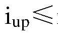
5203 , 接收到无模式按键切换操作, 工作模式不切换, 此时将当前的动力电池的 SOC值、 动力电池的最大允许放电功率 Pb、 检测的混合动力汽车的坡度信号 i与三者 的设定阈值分别比较, 即 SOC下限阈值 SOCd。wn例如 20%, 动力电池的最大允许放电 功率下限阈值 Pbd。wn例如 12KW, 坡度上限阈值 iup例如 15%, 并判断是否满足 SOC
SOCdown Pbi¾Pbdown
 i o
i o
5204, 若至少满足步骤 S203三个条件中的一个, 混合动力汽车的工作模式则自动 切换至 HEV-s模式, 即言, 如果动力电池的 SOC小于等于第一电量阈值例如 20%, 或 者动力电池的最大允许放电功率小于等于第一功率阈值例如 12KW, 或者混合动力汽 车检测的当前坡度信号大于等于坡度上限阈值例如 15%时, 控制混合动力汽车自动切 换至混合动力运动模式。
5205 , 若步骤 S203三个条件均不满足, 则不进行 HEV-s模式的自动切换, 混合 动力汽车保持 EV-s模式运行。
在 EV-s模式驱动混合动力汽车运行时, 在不进行手动或自动模式切换时电机作为 单动力源一直驱动。 该工作模式不对电机的最大输出扭矩、 功率进行限制, 能获得电 机的最大能力进行驱动, 满足用户在 EV模式下更高的动力性需求(如超车加速、 快速 爬坡等) 。
从混合动力汽车处于 EV-s模式时的控制方法实施例可以看出, 通过判断动力电池 的 SOC 值、 动力电池的最大允许放电功率、 坡度值来控制混合动力汽车自动切换至 HEV-s 模式的策略, 保证了整车持续正常运行的能力, 避免因为某些因素而导致动力 性能下降的可能。 综上可知, 上述混合动力汽车处于 EV-s模式时的控制方法适用于既 希望纯电动运行又希望获得更好动力感的用户, 工作模式更加灵活多变, 使用户能够 获得更多驾乘快感。
在本发明的又一个实施例中, 如图 5 所示, 当混合动力汽车处于混合动力经济模 式运行时的混合动力汽车的控制方法包括如下步骤:
S301 , 获取 EV模式按键切换信息, 判断是否进行手动切换 EV模式, 如果是, 则 进入步骤 S302或者步骤 S303 ; 如果否, 则进入步骤 S306。
S302,接收到有 EV模式按键切换操作,则将当前动力电池的 SOC值与设定的 SOC 上限阈值 SOCup例如 30%进行比较, 判断是否满足 SOCup SOC, 如果是, 则进入步 骤 S303 ; 如果否, 则进入步骤 S305。
5303 , 将当前车速与设定的车速阈值 Vmax例如 150km/h即允许 HEV模式切换至 EV模式的最高车速进行比较, 判断是否满足 v Vmax, 如果是, 则进入步骤 S304 ; 如 果否, 则进入步骤 S305。
5304 , 控制混合动力汽车切换至 EV-eco模式并执行相应动力系统控制策略。 也就是说, 当混合动力汽车处于混合动力经济模式时, 控制器在接收到切换至纯 电动经济模式的切换指令之后, 如果判断动力电池的 SOC大于等于第二电量阈值例如 30% , 且混合动力汽车的当前车速小于等于第一速度阈值例如 150km/h 时, 控制器控 制混合动力汽车切换至纯电动经济模式。
5305 , 混合动力汽车保持 HEV-eco模式运行。
5306 , 接收到无 EV模式按键切换操作, 则获取 Sport模式按键切换信息, 判断是 否进行手动切换 Sport模式, 如果是, 则进入步骤 S307 ; 如果否, 则进入步骤 S308。
5307 , 接收到有 Sport模式按键切换操作, 则控制混合动力汽车切换至 HEV-s模 式并执行相应动力系统控制策略。
5308 , 接收到无 Sport模式按键切换操作, 则混合动力汽车的工作模式不切换, 并
获取坡度信息, 将当前坡度值 i与设定的坡度上下限阈值 iup例如 15% id。wn例如 5% 进行比较, 判断 i值所在区间。
5309, 判定 i idown, 进入下一步骤 S310
5310, 将当前动力电池的 SOC值、 动力电池的最大允许放电功率 Pb与两者的设 定阈值分别比较, 即 SOC上下限阈值 SOCup例如 30% SOCd。wn例如 20%, 动力电池 的最大允许放电功率上下限阈值 Pbup例如 30KW Pbd。wn例如 12KW, 判断 SOC Pb 所在区间。
5311, 判定 SOCup SOC且 Pbup Pb, 进入步骤 S312
5312, 混合动力汽车按经济策略工作流程进行控制。
也就是说, 当混合动力汽车处于混合动力经济模式时, 如果混合动力汽车检测的 当前坡度信号小于等于坡度下限阈值例如 5%, 且动力电池的 SOC大于等于第二电量 阈值例如 30%、 动力电池的最大允许放电功率大于等于第二功率阈值例如 30KW, 控 制器控制混合动力汽车以经济方式运行。
S313,判定 30 叩>300>30^ 11且1¾叩 ?15,或者 SOCup SOC且 Pbup>Pb>Pbdown 进入步骤 S314
5314, 混合动力汽车按原策略工作流程进行控制, 即原来是以经济方式运行则仍 按经济策略流程执行, 原来是以低电方式运行则仍按低电策略流程执行。
5315, 判定30 5^001。%111或者1¾ ?1¼^11, 进入步骤 S316
5316, 混合动力汽车按低电策略工作流程进行控制。
也就是说, 当混合动力汽车处于混合动力经济模式时, 如果混合动力汽车检测的 当前坡度信号小于等于坡度下限阈值例如 5%且动力电池的 SOC小于等于第一电量阈 值例如 20%,或者混合动力汽车检测的当前坡度信号小于等于坡度下限阈值例如 5%且 动力电池的最大允许放电功率小于等于第一功率阈值例如 12KW, 控制器控制混合动 力汽车以低电方式运行, 其中, 第二电量阈值大于第一电量阈值, 第二功率阈值大于 第一功率阈值。
5317, 判定 iup>i>id。wn, 进入步骤 S318
5318, 混合动力汽车按原策略工作流程进行控制, 即分别保持 i id。 或 iupi ^时 的控制策略。
5319, 判定 iup i, 进入步骤 S320
5320, 控制混合动力汽车按照在经济方式运行的基础上取消低速纯电动、 取消发 动机上限并取消电机上限的工作流程执行。
需要说明的是, 在本发明的实施例中, 低电方式是指发动机带动电机快速发电, 从而摆脱低电状态, 使电机重新具备调节发动机工作区间的能力, 从而保障整车经济 性。
在本实施例中, 如图 6所示, 当混合动力汽车以经济方式运行时的混合动力汽车 的控制方法包括如下步骤:
5401 , 获取混合动力汽车的当前车速信息, 并将当前车速与设定的车速上下限阈 值 vup例如 30km/h、 vdown例如 15km/h进行比较, 判断 v值所在区间。
5402, 判定 vup v, 进入步骤 S403。
5403 ,判定整车的扭矩需求大于如图 7中所示的扭矩上限曲线时,进入步骤 S404。
5404 , 判断混合动力汽车的动力系统是否有故障, 如果是, 则执行步骤 S406; 如 果否, 则执行步骤 S405。
5405 , 动力系统无故障, 则控制发动机按扭矩上限曲线输出, 剩余扭矩需求由电 机补足, 即言, 当混合动力汽车以经济方式运行时, 如果混合动力汽车的车速大于等 于第三速度阈值例如 30km/h时, 其中, 当混合动力汽车的整车扭矩需求大于发动机的 预设扭矩上限曲线时, 控制器控制发动机以预设扭矩上限曲线进行扭矩输出, 并控制 电机进行扭矩补足。
5406 , 动力系统出现故障, 则执行故障处理。
5407 , 判定整车扭矩需求小于如图 7中所示的扭矩下限曲线时, 进入步骤 S408。
5408 , 判断混合动力汽车的动力系统是否有故障, 如果是, 则执行步骤 S410; 如 果否, 则执行步骤 S409。
5409 , 若动力系统无故障, 则发动机按扭矩下限曲线输出, 多余动力用于电机发 电, 即言, 当混合动力汽车以经济方式运行时, 如果混合动力汽车的车速大于等于第 三速度阈值例如 30km/h时, 当混合动力汽车的整车扭矩需求小于发动机的预设扭矩下 限曲线时, 控制器控制发动机以预设扭矩下限曲线进行扭矩输出, 并控制电机进行发 电。
5410, 动力系统出现故障, 则执行故障处理。
5411 , 判定整车扭矩需求界于如图 7 中所示的扭矩上下限曲线之间, 进入步骤 S412。
5412, 判断混合动力汽车的动力系统是否有故障, 如果是, 则执行步骤 S414; 如 果否, 则执行步骤 S413。
5413 , 发动机优先满足整车扭矩需求, 并多输出一部分扭矩用于发电, 即言, 当
混合动力汽车以经济方式运行时, 如果混合动力汽车的车速大于等于第三速度阈值例 如 30km/h时, 当混合动力汽车的整车扭矩需求小于等于发动机的预设扭矩上限曲线且 大于等于发动机的预设扭矩下限曲线时, 控制器控制发动机满足整车扭矩需求进行扭 矩输出, 并控制电机进行发电。 其中, 发电原则遵循如图 8所示的发电功率与 SOC值 对应曲线关系, 同时要满足以下两个前提条件: ①折算到电机端的发电扭矩不超过 Tmmax; ②发动机总输出扭矩不超过如图 7所示的扭矩上限曲线, 若由发电功率曲线计 算得到的发动机扭矩超出了以上两个条件中的任何一个, 则按以上两个条件作为上限 共同制约用于发电的那部分发动机扭矩。
5414 , 动力系统出现故障, 则执行故障处理。
5415 , 判定 vup>v>Vd。wn, 进入步骤 S416。
5416 , 判断混合动力汽车的动力系统是否有故障, 如果是, 则执行步骤 S418 ; 如 果否, 则执行步骤 S417。
5417 , 若动力系统无故障, 则动力系统按原策略工作流程进行控制, 即原来电机 单独驱动则仍按该方式运行, 若原来电机辅助发动机驱动或发电则仍按该方式运行。
5418 , 动力系统出现故障, 则执行故障处理。
5419 , 判定 v vd。wn, 进入步骤 S420。
5420, 判断混合动力汽车的动力系统是否有故障, 如果是, 则执行步骤 S422; 如 果否, 则执行步骤 S421。
5421 , 若动力系统无故障, 则电机单独驱动, 发动机熄火, 即言, 当混合动力汽 车以经济方式运行时,如果混合动力汽车的车速小于等于第二速度阈值例如 15km/h时, 控制器控制混合动力汽车纯电动行驶, 即混合动力汽车纯电动运行。
5422, 动力系统出现故障, 则执行故障处理。
在本实施例中, 如图 9所示, 当混合动力汽车以低电方式运行时的混合动力汽车 的控制方法包括如下步骤:
5501 , 获取换挡模式信息, 判断混合动力汽车的当前执行档位。
5502, 判定混合动力汽车执行非 P挡时, 进入步骤 S503。
5503 , 判定整车扭矩需求大于如图 7中所示的扭矩上限曲线, 进入步骤 S504。
5504 , 判断混合动力汽车的动力系统是否有故障, 如果是, 则执行步骤 S506; 如 果否, 则执行步骤 S505。
5505 , 若动力系统无故障, 则发动机按扭矩上限曲线输出, 剩余扭矩需求由电机 补足, 即言, 当混合动力汽车以低电方式运行时, 如果混合动力汽车的当前档位处于
非 P挡时, 其中, 当混合动力汽车的整车扭矩需求大于发动机的预设扭矩上限曲线时, 控制器控制发动机以预设扭矩上限曲线进行扭矩输出, 并控制电机进行扭矩补足。
5506 , 若动力系统出现故障, 则执行故障处理。
5507 , 判定整车扭矩需求小于如图 7中所示的扭矩下限曲线时, 进入步骤 S508。
5508 , 判断混合动力汽车的动力系统是否有故障, 如果是, 则执行步骤 S510; 如 果否, 则执行步骤 S509。
5509 , 若动力系统无故障, 则发动机按扭矩下限曲线输出, 多余动力用于电机发 电, 即言, 当混合动力汽车以低电方式运行时, 如果混合动力汽车的当前档位处于非 P 挡时, 当混合动力汽车的整车扭矩需求小于发动机的预设扭矩下限曲线时, 控制器控 制发动机以预设扭矩下限曲线进行扭矩输出, 并控制电机进行发电。
5510, 若动力系统出现故障, 则执行故障处理。
5511 , 判定整车扭矩需求界于如图 7 中所示的扭矩上下限曲线之间, 进入步骤 S512。
5512, 判断混合动力汽车的动力系统是否有故障, 如果是, 则执行步骤 S514; 如 果否, 则执行步骤 S513。
5513 , 发动机优先满足整车扭矩需求, 并多输出一部分扭矩用于发电, 即言, 当 混合动力汽车以低电方式运行时, 如果混合动力汽车的当前档位处于非 P挡时, 当混 合动力汽车的整车扭矩需求小于等于发动机的预设扭矩上限曲线且大于等于发动机的 预设扭矩下限曲线时, 控制器控制发动机满足整车扭矩需求进行扭矩输出, 并控制电 机进行发电。 其中, 发电原则遵循如图 8所示的发电功率与 SOC值对应曲线关系, 同 时要满足以下两个前提条件: ①折算到电机端的发电扭矩不超过 Tmmax; ②发动机总输 出扭矩不超过如图 7所示的扭矩上限曲线, 若由发电功率曲线计算得到的发动机扭矩 超出了以上两个条件中的任何一个, 则按以上两个条件作为上限共同制约用于发电的 那部分发动机扭矩。
5514 , 若动力系统出现故障, 则执行故障处理。
5515 , 判定混合动力汽车执行 P挡时, 进入步骤 S516。
5516 , 执行 P挡怠速启停策略, 即言, 当混合动力汽车以低电方式运行时, 如果 混合动力汽车的当前档位处于 P挡时, 控制器控制混合动力汽车进入怠速启停模式, 在该模式下, 当混合动力汽车满足怠速启停条件, 发动机熄火。
在 HEV-eco模式驱动混合动力汽车运行时, 电机与发动机相互配合以提高能量利 用率, 大体方向是当整车工作在发动机非经济区域内时, 电机的使用比例大幅提高,
而当整车工作在发动机经济区域内时, 发动机又会发一部分电来给电池充电, 而且电 量越低发电功率会越高, 同时该模式的整个策略将电机的输出功率限制为 Pmmax以避 免长时间大功率用电, 从而保证了电池电量始终保持在一个较高的水平, 促使电机时 刻有电能去调节发动机使其工作在高效区, 这样最终的效果是使混合动力驱动时的油 耗尽可能降低, 保证了经济性能和排放性能。 而当整车需要大负荷输出时, 电机又可 辅助发动机共同驱动, 动力性能较 EV模式有大幅提升。 当用户需要长途行驶, 且希望 尽量降油耗的情况下可选用该模式。
在本发明的再一个实施例中, 如图 10所示, 当混合动力汽车处于混合动力运动模 式运行时的混合动力汽车的控制方法包括如下步骤:
S601 , 获取 EV模式按键切换信息, 判断是否进行手动切换 EV模式, 如果是, 则 进入步骤 S602或者步骤 S603 ; 如果否, 则进入步骤 S606。
S602,接收到有 EV模式按键切换操作,则将当前动力电池的 SOC值与设定的 SOC 上限阈值 SOCup例如 30%进行比较, 判断是否满足 SOCup SOC, 如果是, 则进入步 骤 S603 ; 如果否, 则进入步骤 S605。
5603 , 将当前车速与设定的车速阈值 Vmax例如 150km/h即允许 HEV模式切换至 EV模式的最高车速进行比较, 判断是否满足 v Vmax, 如果是, 则进入步骤 S604 ; 如 果否, 则进入步骤 S605。
5604 , 控制混合动力汽车切换至 EV-s模式并执行相应动力系统控制策略。
也就是说, 当混合动力汽车处于混合动力运动模式时, 控制器在接收到切换至纯 电动运动模式的切换指令之后, 如果判断动力电池的 SOC大于等于第二电量阈值例如 30% , 且混合动力汽车的当前车速小于等于第一速度阈值例如 150km/h 时, 控制器控 制混合动力汽车切换至纯电动运动模式。
5605 , 混合动力汽车保持 HEV-s模式运行。
5606 , 接收到无 EV模式按键切换操作, 则获取 eco模式按键切换信息, 判断是否 进行手动切换 eco模式, 如果是, 则进入步骤 S607 ; 如果否, 则进入步骤 S608。
5607 , 接收到有 eco模式按键切换操作, 则控制混合动力汽车切换至 HEV-eco模 式并执行相应动力系统控制策略。
5608 , 接收到无 eco 模式按键切换操作, 则混合动力汽车的工作模式不切换, 获 取换挡模式信息, 判断混合动力汽车的当前执行档位。
5609 , 判定混合动力汽车执行 P挡时, 进入步骤 S610。
5610, 执行 P挡怠速启停策略, 即言, 当混合动力汽车处于混合动力运动模式时,
如果混合动力汽车的当前档位处于 P挡时, 控制器控制混合动力汽车进入怠速启停模 式。
5611 , 判定混合动力汽车执行非 P挡时, 进入步骤 S612。
5612, 将整车需求扭矩与发动机峰值扭矩进行比较, 判断是否满足整车需求扭矩 > 发动机峰值扭矩, 如果是, 则执行步骤 S613 ; 如果否, 则执行步骤 S614。
5613 , 发动机按峰值扭矩输出, 剩余扭矩需求由电机补足, 当电机受自身或动力 电池当前能力限制时, 按电机、 动力电池当前的最大能力驱动。 也就是说, 当混合动 力汽车处于混合动力运动模式时, 如果混合动力汽车的当前档位处于非 P挡时, 其中, 当混合动力汽车的整车扭矩需求大于发动机的预设峰值扭矩时, 控制器控制发动机按 照预设峰值扭矩进行扭矩输出, 并控制电机进行扭矩补足。
5614, 发动机优先满足整车扭矩需求, 并多输出一部分扭矩用于发电, 即言, 当 混合动力汽车处于混合动力运动模式时, 如果混合动力汽车的当前档位处于非 P挡时, 当混合动力汽车的整车扭矩需求小于等于发动机的预设峰值扭矩时, 控制器控制发动 机满足整车扭矩需求进行扭矩输出, 并控制电机进行发电。 其中, 发电原则遵循如图 8 所示的发电功率与 SOC值对应曲线关系, 同时要满足以下两个前提条件: ①折算到电 机端的发电扭矩不超过 Tmmax;②发动机总输出扭矩不超过如图 7所示的发动机扭矩峰 值, 若由发电功率曲线计算得到的发动机扭矩超出了以上两个条件中的任何一个, 则 按以上两个条件作为上限共同制约用于发电的那部分发动机扭矩。
在 HEV-s模式驱动混合动力汽车运行时, 当换挡模式为非 P挡时, 发动机一直处 于起动状态, 只有当换挡模式为 P挡, 且满足 P挡怠速启停条件时, 发动机才会熄火。 该 HEV-s模式的整个策略不再限制发动机、 电机的最大输出扭矩、 功率, 能发挥动力 系统的最大驱动能力, 是四种驱动模式中动力性能最好的一种, 但由于行车过程中发 动机是一直运行的, 要么与电机配合驱动要么边驱动边带电机发电 (动力电池的电量 低于一定值时) , 因此油耗相对较高, 经济性能无法保证。 该 HEV-s模式适用于对行 车动力性要求较高的用户, 能拥有等同于大排量豪华燃油车的充沛动力, 最大程度的 提高用户的加速快感。
在本发明的实施例中,通过 EV、HEV、 eco、 Sport四个按键的切换,可获得 EV-eco、 EV-s、 HEV-eco、 HEV-s四种不同的工作模式, 根据整车动力性、 经济性对于四种工作 模式的不同定义, 动力系统驱动策略的侧重点各不相同。 并且, 混合动力汽车的动力 系统采用并联方式, 而不是串联或者混联。 此外, 在驱动策略中对发动机启动点进行 了优化, 车速判断点提高, 增加了坡度判断, 取消了需求功率的判断。 在 HEV-eco模
式下的经济策略中将发动机工作区域限制在上下限扭矩曲线之间, 发电功率采用了以 SOC值为自变量的动态变化曲线。
根据本发明实施例的混合动力汽车的控制方法, 多种可选择的工作模式能满足用 户在不同工况下的驾驶需求, 即可满足城市工况的只用电需求, 又可满足郊区工况的 动力性需求, 真正做到整车驱动以用户的主观操作意图为导向, 提高驾驶乐趣。 其中, 混合动力汽车的控制系统采用并联方式, 相较于串联方式的能量多步转换, 能有效提 高能量利用率, 同时并联结构相对简单, 避免混联方式繁琐的 ECVT匹配, 降低因匹 配不良造成的不平顺性风险。 并且, 驱动策略中对发动机启动点的优化避免了发动机 过早过频启动, 可有效降低起动噪声提高启动系统寿命以及因频繁起动造成低压电频 繁拉低的风险, 保障其他低压用电设备的正常运行, 同时对发动机工作区域进行了优 化, 保证发动机始终工作在高效区, 以及对发电功率进行了优化, 保证行车过程中有 较高的电量均衡点, 有利于整车大多数时间处于经济策略中, 能有效降低油耗。 此外, 该控制方法能够保证了整车纯电动运行的动力性和续驶里程, 在满足整车动力性需求 的前提下避免长期大功率的用电以提高用电效率, 同时还避免发动机频繁启停现象, 从而提高了起动机的寿命, 减少了行车噪声, 提高了驾驶舒适性。
流程图中或在此以其他方式描述的任何过程或方法描述可以被理解为, 表示包括 一个或更多个用于实现特定逻辑功能或过程的步骤的可执行指令的代码的模块、 片段 或部分, 并且本发明的优选实施方式的范围包括另外的实现, 其中可以不按所示出或 讨论的顺序, 包括根据所涉及的功能按基本同时的方式或按相反的顺序, 来执行功能, 这应被本发明的实施例所属技术领域的技术人员所理解。
在流程图中表示或在此以其他方式描述的逻辑和 /或步骤, 例如, 可以被认为是用 于实现逻辑功能的可执行指令的定序列表, 可以具体实现在任何计算机可读介质中, 以供指令执行系统、 装置或设备 (如基于计算机的系统、 包括处理器的系统或其他可 以从指令执行系统、 装置或设备取指令并执行指令的系统) 使用, 或结合这些指令执 行系统、装置或设备而使用。就本说明书而言, "计算机可读介质"可以是任何可以包含、 存储、 通信、 传播或传输程序以供指令执行系统、 装置或设备或结合这些指令执行系 统、 装置或设备而使用的装置。 计算机可读介质的更具体的示例 (非穷尽性列表) 包 括以下: 具有一个或多个布线的电连接部(电子装置), 便携式计算机盘盒(磁装置), 随机存取存储器 (RAM) , 只读存储器 (ROM) , 可擦除可编辑只读存储器 (EPROM 或闪速存储器) , 光纤装置, 以及便携式光盘只读存储器 (CDROM) 。 另外, 计算机 可读介质甚至可以是可在其上打印所述程序的纸或其他合适的介质, 因为可以例如通
过对纸或其他介质进行光学扫描, 接着进行编辑、 解译或必要时以其他合适方式进行 处理来以电子方式获得所述程序, 然后将其存储在计算机存储器中。
应当理解, 本发明的各部分可以用硬件、 软件、 固件或它们的组合来实现。 在上 述实施方式中, 多个步骤或方法可以用存储在存储器中且由合适的指令执行系统执行 的软件或固件来实现。 例如, 如果用硬件来实现, 和在另一实施方式中一样, 可用本 领域公知的下列技术中的任一项或他们的组合来实现: 具有用于对数据信号实现逻辑 功能的逻辑门电路的离散逻辑电路, 具有合适的组合逻辑门电路的专用集成电路, 可 编程门阵列 (PGA) , 现场可编程门阵列 (FPGA) 等。
本技术领域的普通技术人员可以理解实现上述实施例方法携带的全部或部分步骤 是可以通过程序来指令相关的硬件完成, 所述的程序可以存储于一种计算机可读存储 介质中, 该程序在执行时, 包括方法实施例的步骤之一或其组合。
此外, 在本发明各个实施例中的各功能单元可以集成在一个处理模块中, 也可以 是各个单元单独物理存在, 也可以两个或两个以上单元集成在一个模块中。 上述集成 的模块既可以采用硬件的形式实现, 也可以采用软件功能模块的形式实现。 所述集成 的模块如果以软件功能模块的形式实现并作为独立的产品销售或使用时, 也可以存储 在一个计算机可读取存储介质中。
上述提到的存储介质可以是只读存储器, 磁盘或光盘等。
在本说明书的描述中, 参考术语"一个实施例"、 "一些实施例"、 "示例"、 "具体示 例"、 或"一些示例"等的描述意指结合该实施例或示例描述的具体特征、 结构、 材料或 者特点包含于本发明的至少一个实施例或示例中。 在本说明书中, 对上述术语的示意 性表述不一定指的是相同的实施例或示例。 而且, 描述的具体特征、 结构、 材料或者 特点可以在任何的一个或多个实施例或示例中以合适的方式结合。
尽管已经示出和描述了本发明的实施例, 对于本领域的普通技术人员而言, 可以 理解在不脱离本发明的原理和精神的情况下可以对这些实施例进行多种变化、 修改、 替换和变型, 本发明的范围由所附权利要求及其等同限定。
Claims
1、 一种混合动力汽车的控制系统, 其特征在于, 包括:
传动装置, 所述传动装置用于驱动混合动力汽车的车轮;
发动机动力子系统, 所述发动机动力子系统与所述传动装置相连;
电机动力子系统, 所述电机动力子系统与所述传动装置相连; 以及
控制器, 所述控制器通过控制所述发动机动力子系统和电机动力子系统以控制所 述混合动力汽车进入相应的工作模式, 其中, 所述工作模式包括纯电动模式和混合动 力模式, 并且当所述电机动力子系统中的动力电池的 SOC小于等于第一电量阈值, 或 者所述动力电池的最大允许放电功率小于等于第一功率阈值, 或者所述混合动力汽车 检测的当前坡度信号大于等于坡度上限阈值时, 所述控制器控制所述混合动力汽车从 所述纯电动模式切换至所述混合动力模式。
2、 如权利要求 1所述的混合动力汽车的控制系统, 其特征在于, 所述纯电动模式 包括纯电动经济模式和纯电动运动模式, 所述混合动力模式包括混合动力经济模式和 混合动力运动模式。
3、 如权利要求 2所述的混合动力汽车的控制系统, 其特征在于,
当所述混合动力汽车处于所述纯电动经济模式时, 所述动力电池的当前输出功率 上限小于第一预设功率;
当所述混合动力汽车处于所述纯电动运动模式时, 所述动力电池的当前输出功率 上限小于第二预设功率, 其中, 所述第二预设功率大于所述第一预设功率;
当所述混合动力汽车处于所述混合动力经济模式时, 所述动力电池的当前输出功 率上限和所述发动机动力子系统中的发动机的当前输出功率上限均小于所述第一预设 功率, 且所述发动机的当前输出扭矩上限小于第一扭矩阈值;
当所述混合动力汽车处于所述混合动力运动模式时, 所述动力电池的当前输出功 率上限小于所述第二预设功率, 且所述发动机允许当前输出扭矩上限和当前输出功率 上限进行输出。
4、 如权利要求 3所述的混合动力汽车的控制系统, 其特征在于, 所述第一预设功 率为 70KW, 所述第二预设功率为 110KW, 所述第一扭矩阈值为 185Ν·Μ。
5、 如权利要求 2所述的混合动力汽车的控制系统, 其特征在于, 当所述混合动力 汽车处于所述纯电动经济模式时, 如果判断所述动力电池的 SOC小于等于所述第一电
量阈值, 或者所述动力电池的最大允许放电功率小于等于所述第一功率阈值, 或者所 述混合动力汽车检测的当前坡度信号大于等于所述坡度上限阈值时, 所述控制器控制 所述混合动力汽车切换至所述混合动力经济模式。
6、 如权利要求 2所述的混合动力汽车的控制系统, 其特征在于, 当所述混合动力 汽车处于所述纯电动运动模式时, 如果判断所述动力电池的 SOC小于等于所述第一电 量阈值, 或者所述动力电池的最大允许放电功率小于等于所述第一功率阈值, 或者所 述混合动力汽车检测的当前坡度信号大于等于所述坡度上限阈值时, 所述控制器控制 所述混合动力汽车切换至所述混合动力运动模式。
7、 如权利要求 2所述的混合动力汽车的控制系统, 其特征在于, 当所述混合动力 汽车处于所述纯电动经济模式时, 所述控制器控制所述混合动力汽车限功率运行。
8、 如权利要求 5或 6所述的混合动力汽车的控制系统, 其特征在于, 当所述混合 动力汽车处于所述纯电动经济模式或纯电动运动模式时, 如果接收到用户的模式切换 指令, 则所述控制器控制所述混合动力汽车切换至与所述用户的模式切换指令对应的 目标模式。
9、一种混合动力汽车的控制方法, 其特征在于, 所述混合动力汽车包括传动装置、 发动机动力子系统和电机动力子系统, 所述传动装置与所述发动机动力子系统和所述 电机动力子系统分别相连, 所述控制方法包括以下步骤:
所述混合动力汽车运行时, 通过控制所述发动机动力子系统和电机动力子系统以 控制所述混合动力汽车进入相应的工作模式, 其中, 所述工作模式包括纯电动模式和 混合动力模式;
检测所述电机动力子系统中的动力电池的工作状态, 并检测所述混合动力汽车的 当前坡度信号;
当所述动力电池的 SOC小于等于第一电量阈值, 或者所述动力电池的最大允许放 电功率小于等于第一功率阈值或者所述混合动力汽车的当前坡度信号大于等于坡度上 限阈值时, 控制所述混合动力汽车从所述纯电动模式切换至所述混合动力模式。
10、 如权利要求 9所述的混合动力汽车的控制方法, 其特征在于, 所述纯电动模 式包括纯电动经济模式和纯电动运动模式, 所述混合动力模式包括混合动力经济模式 和混合动力运动模式。
1 1、 如权利要求 10所述的混合动力汽车的控制方法, 其特征在于, 当所述混合动 力汽车处于所述纯电动经济模式时, 如果判断所述动力电池的 SOC小于等于所述第一 电量阈值, 或者所述动力电池的最大允许放电功率小于等于所述第一功率阈值, 或者
所述混合动力汽车的当前坡度信号大于等于所述坡度上限阈值时, 控制所述混合动力 汽车切换至所述混合动力经济模式。
12、 如权利要求 10所述的混合动力汽车的控制方法, 其特征在于, 当所述混合动 力汽车处于所述纯电动运动模式时, 如果判断所述动力电池的 SOC小于等于所述第一 电量阈值, 或者所述动力电池的最大允许放电功率小于等于所述第一功率阈值, 或者 所述混合动力汽车的当前坡度信号大于等于所述坡度上限阈值时, 控制所述混合动力 汽车切换至所述混合动力运动模式。
13、 如权利要求 10所述的混合动力汽车的控制方法, 其特征在于, 当所述混合动 力汽车处于所述纯电动经济模式时, 控制所述混合动力汽车限功率运行。
14、 如权利要求 10所述的混合动力汽车的控制方法, 其特征在于, 当所述混合动 力汽车处于所述纯电动经济模式或纯电动运动模式时, 如果接收到用户的模式切换指 令, 控制所述混合动力汽车切换至与所述用户的模式切换指令对应的目标模式。
Priority Applications (2)
| Application Number | Priority Date | Filing Date | Title |
|---|---|---|---|
| US14/917,895 US10077040B2 (en) | 2013-09-09 | 2014-09-03 | Hybrid electrical vehicle and method for controlling same |
| EP14842721.4A EP3045366A4 (en) | 2013-09-09 | 2014-09-03 | Hybrid electrical vehicle control system and method |
Applications Claiming Priority (4)
| Application Number | Priority Date | Filing Date | Title |
|---|---|---|---|
| CN201310409911.5 | 2013-09-09 | ||
| CN201310409911 | 2013-09-09 | ||
| CN201310558062.XA CN104417347B (zh) | 2013-09-09 | 2013-11-11 | 混合动力汽车的控制系统和控制方法 |
| CN201310558062.X | 2013-11-11 |
Publications (1)
| Publication Number | Publication Date |
|---|---|
| WO2015032324A1 true WO2015032324A1 (zh) | 2015-03-12 |
Family
ID=52627809
Family Applications (1)
| Application Number | Title | Priority Date | Filing Date |
|---|---|---|---|
| PCT/CN2014/085830 Ceased WO2015032324A1 (zh) | 2013-09-09 | 2014-09-03 | 混合动力汽车的控制系统和控制方法 |
Country Status (4)
| Country | Link |
|---|---|
| US (1) | US10077040B2 (zh) |
| EP (1) | EP3045366A4 (zh) |
| CN (1) | CN104417347B (zh) |
| WO (1) | WO2015032324A1 (zh) |
Families Citing this family (33)
| Publication number | Priority date | Publication date | Assignee | Title |
|---|---|---|---|---|
| CN104417554B (zh) | 2013-09-09 | 2018-03-13 | 比亚迪股份有限公司 | 混合动力汽车及其的巡航控制方法 |
| CN104417344B (zh) * | 2013-09-09 | 2017-03-15 | 比亚迪股份有限公司 | 混合动力汽车及其的驱动控制方法 |
| CN104417543B (zh) | 2013-09-09 | 2017-08-22 | 比亚迪股份有限公司 | 混合动力汽车的控制系统和控制方法 |
| CN104417557B (zh) | 2013-09-09 | 2017-07-04 | 比亚迪股份有限公司 | 一种车辆的滑行回馈控制系统及其控制方法 |
| CN104417347B (zh) | 2013-09-09 | 2017-08-04 | 比亚迪股份有限公司 | 混合动力汽车的控制系统和控制方法 |
| CN104417346B (zh) | 2013-09-09 | 2017-04-12 | 比亚迪股份有限公司 | 混合动力汽车的控制系统和控制方法 |
| CN104417544B (zh) | 2013-09-09 | 2017-08-22 | 比亚迪股份有限公司 | 混合动力汽车的控制系统和控制方法 |
| US9718456B2 (en) * | 2015-03-26 | 2017-08-01 | Ford Global Technologies, Llc | Torque assist based on battery state of charge allocation |
| US10150358B2 (en) * | 2015-12-17 | 2018-12-11 | Erik Orlando Soto | Generator and electrical motor for multi-axle vehicles |
| JP6326403B2 (ja) * | 2015-12-25 | 2018-05-16 | 本田技研工業株式会社 | ハイブリッド車両 |
| CN105667500B (zh) * | 2016-02-29 | 2018-01-02 | 潍柴动力股份有限公司 | 单轴并联混合动力公交车电量平衡自适应标定方法 |
| CN107471995A (zh) * | 2016-08-23 | 2017-12-15 | 宝沃汽车(中国)有限公司 | 插电式混合动力汽车的动力系统及其控制方法 |
| KR102331762B1 (ko) * | 2017-06-08 | 2021-11-26 | 현대자동차주식회사 | 하이브리드 자동차 및 그를 위한 변속 패턴 제어 방법 |
| CN109795476B (zh) * | 2019-01-29 | 2020-06-30 | 四川阿尔特新能源汽车有限公司 | 发动机启动控制方法及装置 |
| US11511642B2 (en) | 2019-04-05 | 2022-11-29 | Oshkosh Corporation | Electric concrete vehicle systems and methods |
| CN110341693A (zh) * | 2019-07-08 | 2019-10-18 | 高晓杰 | 双电机增程驱动混合动力车辆串联模式进入方法及系统 |
| US10981024B1 (en) | 2019-10-11 | 2021-04-20 | Oshkosh Corporation | Hybrid fire fighting vehicle |
| CN112904209B (zh) * | 2019-11-19 | 2023-04-18 | 北京车和家信息技术有限公司 | 一种动力电池功率持续时长的预测方法及装置 |
| US11417916B2 (en) | 2020-01-13 | 2022-08-16 | Ford Global Technologies, Llc | Intelligent vehicle battery charging for high capacity batteries |
| KR102855178B1 (ko) * | 2020-04-20 | 2025-09-04 | 현대자동차주식회사 | 차량의 등판 주행 제어 방법 |
| CN113715801B (zh) * | 2020-05-22 | 2024-05-10 | 广州汽车集团股份有限公司 | 具有混合动力耦合系统的车辆的控制器、控制方法和车辆 |
| CN113715802B (zh) * | 2020-05-22 | 2024-05-17 | 广州汽车集团股份有限公司 | 具有混合动力耦合系统的车辆的控制器、控制方法和车辆 |
| CN113715804B (zh) * | 2020-05-22 | 2024-04-12 | 广汽埃安新能源汽车有限公司 | 具有混合动力耦合系统的车辆的控制器、控制方法和车辆 |
| CN114312735A (zh) * | 2020-09-30 | 2022-04-12 | 深圳臻宇新能源动力科技有限公司 | 混合动力车辆的能量管理方法、装置和整车控制器 |
| CN112319248B (zh) * | 2020-11-17 | 2022-04-26 | 睿驰电装(大连)电动系统有限公司 | 增程式电动车发动机启动的控制方法和装置 |
| CN112660103B (zh) * | 2020-12-31 | 2023-04-07 | 重庆金康赛力斯新能源汽车设计院有限公司 | 一种车辆控制模式的确定方法、装置和整车控制系统 |
| CN114030458B (zh) * | 2021-11-09 | 2023-12-19 | 东风汽车集团股份有限公司 | 一种混动车控制方法、装置、设备和介质 |
| EP4530117A4 (en) * | 2022-06-30 | 2025-08-06 | Shenzhen Yinwang Intelligent Technology Co Ltd | ACCELERATION COMPENSATION METHOD AND APPARATUS, AND VEHICLE |
| DE102022210439B4 (de) * | 2022-09-30 | 2025-11-06 | Volkswagen Aktiengesellschaft | Verfahren zur Steuerung eines Antriebsstrangs in einem Hybrid-Fahrzeug und Hybrid-Fahrzeug |
| CN115503763B (zh) * | 2022-10-24 | 2025-09-05 | 中车大连机车车辆有限公司 | 调车机车的动力模式切换控制方法 |
| WO2024139357A1 (zh) * | 2022-12-27 | 2024-07-04 | 广州汽车集团股份有限公司 | 混合动力机电耦合装置、车辆及控制方法 |
| KR20250070777A (ko) * | 2023-11-14 | 2025-05-21 | 현대자동차주식회사 | 주행 상황에 따른 능동적 가속도 제한을 위한 방법 및 차량 |
| CN118953330B (zh) * | 2024-10-17 | 2025-01-17 | 潍柴动力股份有限公司 | 一种混合动力系统的发动机控制方法及相关设备 |
Citations (6)
| Publication number | Priority date | Publication date | Assignee | Title |
|---|---|---|---|---|
| CN101161523A (zh) * | 2006-10-12 | 2008-04-16 | 日产自动车株式会社 | 混合动力车辆的模式切换控制装置 |
| CN101687507A (zh) * | 2007-07-12 | 2010-03-31 | 丰田自动车株式会社 | 混合动力车辆及混合动力车辆的控制方法 |
| CN101830219A (zh) * | 2009-03-12 | 2010-09-15 | 福特全球技术公司 | 混合动力电动车辆 |
| CN101830222A (zh) * | 2010-03-01 | 2010-09-15 | 盛能动力科技(深圳)有限公司 | 混合动力车辆及其控制方法 |
| US20110166733A1 (en) * | 2010-01-07 | 2011-07-07 | Ford Global Technologies, Llc | Plug-in hybrid electric vehicle battery state of charge hold function and energy management |
| CN103158695A (zh) * | 2011-12-16 | 2013-06-19 | 北汽福田汽车股份有限公司 | 混合动力汽车动力分配的控制方法 |
Family Cites Families (145)
| Publication number | Priority date | Publication date | Assignee | Title |
|---|---|---|---|---|
| JP3094872B2 (ja) * | 1995-10-20 | 2000-10-03 | トヨタ自動車株式会社 | ハイブリッド車用制御装置 |
| DE19709457A1 (de) * | 1997-03-07 | 1998-09-10 | Mannesmann Sachs Ag | Antriebsanordnung für ein Kraftfahrzeug |
| JP3211751B2 (ja) * | 1997-03-24 | 2001-09-25 | トヨタ自動車株式会社 | 動力出力装置およびその制御方法 |
| JP3767103B2 (ja) * | 1997-07-16 | 2006-04-19 | 日産自動車株式会社 | 電気自動車の制御装置 |
| US6554088B2 (en) | 1998-09-14 | 2003-04-29 | Paice Corporation | Hybrid vehicles |
| JP3525218B2 (ja) | 1998-09-18 | 2004-05-10 | 本田技研工業株式会社 | ハイブリッド車両の回生制御装置 |
| JP4070401B2 (ja) * | 2000-10-31 | 2008-04-02 | 日産ディーゼル工業株式会社 | 車両のハイブリッドシステム |
| US7122979B2 (en) | 2000-12-27 | 2006-10-17 | Transportation Techniques, Llc | Method and apparatus for selective operation of a hybrid electric vehicle in various driving modes |
| JP3835202B2 (ja) | 2001-05-18 | 2006-10-18 | トヨタ自動車株式会社 | 車両用駆動制御装置 |
| JP3535140B2 (ja) | 2002-05-23 | 2004-06-07 | 本田技研工業株式会社 | ハイブリッド車両 |
| JP3612711B2 (ja) | 2002-07-03 | 2005-01-19 | トヨタ自動車株式会社 | 自動車 |
| US7216729B2 (en) * | 2003-09-19 | 2007-05-15 | Ford Global Technologies, Llc | Method and system of requesting engine on/off state in a hybrid electric vehicle |
| CN1238213C (zh) | 2003-10-17 | 2006-01-25 | 清华大学 | 混合动力轿车动力总成的动力输出切换方法及其控制系统 |
| US7653474B2 (en) | 2004-05-14 | 2010-01-26 | Gm Global Technology Operations, Inc. | Method of determining engine output power in a hybrid electric vehicle |
| US7107956B2 (en) * | 2004-07-30 | 2006-09-19 | Ford Global Technologies, Llc | Vehicle and method for controlling engine start in a vehicle |
| JP4239923B2 (ja) | 2004-08-02 | 2009-03-18 | 日産自動車株式会社 | 電動力伝達装置 |
| JP2006094626A (ja) * | 2004-09-24 | 2006-04-06 | Toyota Motor Corp | ハイブリッド車およびその制御方法 |
| JP4327692B2 (ja) * | 2004-09-30 | 2009-09-09 | トヨタ自動車株式会社 | 二次電池の充放電制御装置 |
| US7332881B2 (en) | 2004-10-28 | 2008-02-19 | Textron Inc. | AC drive system for electrically operated vehicle |
| JP2006183547A (ja) | 2004-12-27 | 2006-07-13 | Nissan Motor Co Ltd | ハイブリッド車両のエンジン始動装置 |
| JP4474293B2 (ja) | 2005-01-31 | 2010-06-02 | トヨタ自動車株式会社 | ハイブリッド車およびその制御方法 |
| CN1895942A (zh) | 2005-07-15 | 2007-01-17 | 中国第一汽车集团公司 | 双电机混合动力汽车动力系统控制方法 |
| KR100747796B1 (ko) | 2005-11-17 | 2007-08-08 | 현대자동차주식회사 | 하이브리드차의 경사로 구동 제어장치 및 제어방법 |
| FR2894547B1 (fr) | 2005-12-08 | 2009-06-05 | Renault Sas | Procede et dispositif de controle et de supervision d'un vehicule hybride du type comportant quatre roues motrices |
| JP5247000B2 (ja) | 2005-12-21 | 2013-07-24 | 日産自動車株式会社 | 車両のコースト減速制御装置 |
| FR2896750B1 (fr) | 2006-01-30 | 2009-11-13 | Peugeot Citroen Automobiles Sa | Procede de commande d'un groupe motopropulseur de vehicule automobile |
| US8620498B2 (en) | 2006-06-20 | 2013-12-31 | GM Global Technology Operations LLC | Hybrid road grade determination system |
| CN101096180A (zh) * | 2006-06-30 | 2008-01-02 | 比亚迪股份有限公司 | 四轮驱动混合动力系统及工作方法 |
| DE102006034932A1 (de) * | 2006-07-28 | 2008-01-31 | Dr.Ing.H.C. F. Porsche Ag | Verfahren und Vorrichtung zur Steuerung eines Hybrid-Fahrzeugantriebs |
| US7647994B1 (en) | 2006-10-10 | 2010-01-19 | Belloso Gregorio M | Hybrid vehicle having an electric generator engine and an auxiliary accelerator engine |
| CN1944139A (zh) | 2006-11-08 | 2007-04-11 | 北京理工大学 | 串联式混合动力车辆的整车控制策略 |
| JP4793233B2 (ja) | 2006-11-24 | 2011-10-12 | トヨタ自動車株式会社 | 動力出力装置、それを搭載した車両及びその制御方法 |
| JP4254852B2 (ja) | 2006-12-06 | 2009-04-15 | トヨタ自動車株式会社 | 車両およびその制御方法 |
| US7678005B2 (en) | 2006-12-19 | 2010-03-16 | Chrysler Group Llc | Fixed speed operation in a hybrid transmission including sport and economy modes |
| JP4201044B2 (ja) | 2007-01-09 | 2008-12-24 | トヨタ自動車株式会社 | 車両およびその制御方法 |
| JP5098338B2 (ja) * | 2007-01-10 | 2012-12-12 | 日産自動車株式会社 | ハイブリッド車両 |
| JP4229185B2 (ja) | 2007-01-12 | 2009-02-25 | トヨタ自動車株式会社 | ハイブリッド自動車およびその制御方法 |
| JP4241837B2 (ja) * | 2007-01-15 | 2009-03-18 | トヨタ自動車株式会社 | 車両およびその制御方法 |
| JP4127314B1 (ja) | 2007-02-13 | 2008-07-30 | トヨタ自動車株式会社 | 電動車両制御装置 |
| JP4345824B2 (ja) | 2007-02-21 | 2009-10-14 | トヨタ自動車株式会社 | 車両およびその制御方法 |
| JP4241845B2 (ja) | 2007-03-06 | 2009-03-18 | トヨタ自動車株式会社 | 車両の制御装置、制御方法、その方法を実現するプログラムおよびそのプログラムを記録した記録媒体 |
| DE102007016515A1 (de) | 2007-04-05 | 2008-10-09 | Daimler Ag | Verfahren zur Steuerung eines Antriebssystems für ein Kraftfahrzeug |
| JP2008261244A (ja) | 2007-04-10 | 2008-10-30 | Toyota Motor Corp | 可変バルブタイミング機構の制御装置、制御方法、その方法を実現させるプログラムおよびそのプログラムを記録した記録媒体 |
| KR101114756B1 (ko) | 2007-04-10 | 2012-02-29 | 도요타지도샤가부시키가이샤 | 가변 밸브 타이밍 기구의 제어 유닛 및 제어 방법, 그 제어 방법을 실현시키는 프로그램 및 그 프로그램이 기록된 기록 매체 |
| JP4183013B1 (ja) * | 2007-05-15 | 2008-11-19 | トヨタ自動車株式会社 | 車両およびその制御方法 |
| JP4544273B2 (ja) * | 2007-06-20 | 2010-09-15 | トヨタ自動車株式会社 | 車両用電源装置および車両用電源装置における蓄電装置の充電状態推定方法 |
| CN101445105B (zh) | 2007-11-26 | 2011-07-06 | 比亚迪股份有限公司 | 一种混合动力驱动系统的驱动控制方法 |
| JP4527138B2 (ja) | 2007-07-12 | 2010-08-18 | 本田技研工業株式会社 | ハイブリッド車両の制御装置 |
| CN101186209B (zh) | 2007-09-04 | 2013-01-16 | 深圳先进技术研究院 | 采用电气系统实现混联功率分配的混合动力系统 |
| CN101125548B (zh) * | 2007-09-07 | 2012-10-24 | 南京工业职业技术学院 | 并联式混合动力系统的能量流控制方法 |
| KR100887797B1 (ko) | 2007-09-28 | 2009-03-09 | 현대자동차주식회사 | 하이브리드 차량의 오토크루즈 주행 제어 방법 |
| JP4909863B2 (ja) | 2007-10-04 | 2012-04-04 | 本田技研工業株式会社 | ハイブリッド車両の制御装置 |
| US8043194B2 (en) | 2007-10-05 | 2011-10-25 | Ford Global Technologies, Llc | Vehicle creep control in a hybrid electric vehicle |
| CN101445041B (zh) | 2008-10-11 | 2012-03-21 | 比亚迪股份有限公司 | 一种混合动力驱动系统及采用该系统的汽车 |
| CN201214410Y (zh) | 2007-12-29 | 2009-04-01 | 桂林吉星电子等平衡动力有限公司 | 一种油电混合动力电动车的速度巡航控制装置 |
| CN101214797B (zh) | 2007-12-29 | 2010-08-11 | 奇瑞汽车有限公司 | 一种混合动力汽车电池充放电电流限制保护方法 |
| JP2009166516A (ja) | 2008-01-10 | 2009-07-30 | Toyota Motor Corp | ハイブリッド自動車およびその制御方法 |
| JP2009198223A (ja) | 2008-02-19 | 2009-09-03 | Toyota Motor Corp | 車両およびその制御方法 |
| CN101587212A (zh) | 2008-05-19 | 2009-11-25 | 鸿富锦精密工业(深圳)有限公司 | 套筒及采用该套筒的光纤连接器插座 |
| JP4386138B1 (ja) * | 2008-06-27 | 2009-12-16 | トヨタ自動車株式会社 | ハイブリッド車両の制御装置および制御方法 |
| CN101618718B (zh) | 2008-06-30 | 2013-06-19 | 比亚迪股份有限公司 | 一种混合动力系统及其控制方法 |
| JP4513907B2 (ja) | 2008-06-30 | 2010-07-28 | トヨタ自動車株式会社 | ハイブリッド車両 |
| US8082089B2 (en) | 2008-07-23 | 2011-12-20 | GM Global Technology Operations LLC | Vehicle speed control in a cruise mode using vehicle brakes |
| US8095290B2 (en) | 2008-08-01 | 2012-01-10 | GM Global Technology Operations LLC | Method to control vehicular powertrain by monitoring map preview information |
| JP5330812B2 (ja) | 2008-11-20 | 2013-10-30 | トヨタ自動車株式会社 | ハイブリッド車両 |
| JP4478900B1 (ja) | 2008-12-03 | 2010-06-09 | 本田技研工業株式会社 | 蓄電器加温装置 |
| JP4607222B2 (ja) | 2009-01-27 | 2011-01-05 | 本田技研工業株式会社 | ハイブリッド車両 |
| JP5521340B2 (ja) | 2009-02-06 | 2014-06-11 | 日産自動車株式会社 | ハイブリッド車両の制御装置 |
| JP5265439B2 (ja) | 2009-04-03 | 2013-08-14 | 株式会社デンソー | 燃料噴射弁 |
| JP2010241260A (ja) * | 2009-04-06 | 2010-10-28 | Toyota Motor Corp | ハイブリッド車両の制御装置および制御方法 |
| CN102427980B (zh) | 2009-04-27 | 2014-06-25 | 丰田自动车株式会社 | 混合动力车及其控制方法 |
| CN102427981B (zh) * | 2009-05-19 | 2014-04-23 | 丰田自动车株式会社 | 混合动力车辆及其控制方法 |
| US8177006B2 (en) * | 2009-05-28 | 2012-05-15 | Ford Global Technologies, Llc | Plug-in hybrid electric vehicle |
| KR101360698B1 (ko) | 2009-06-09 | 2014-02-07 | 스미도모쥬기가이고교 가부시키가이샤 | 하이브리드식 쇼벨 및 그 제어방법 |
| SE535739C2 (sv) | 2009-06-10 | 2012-11-27 | Scania Cv Ab | Metod och system för att styra en elmaskin i ett hybridfordon |
| DE102009039615A1 (de) | 2009-09-01 | 2011-03-03 | Bayerische Motoren Werke Aktiengesellschaft | Verfahren zur Steuerung eines rekuperativen Verzögerungssystems für ein Kraftfahrzeug |
| JP4968303B2 (ja) | 2009-09-18 | 2012-07-04 | トヨタ自動車株式会社 | エンジン制御装置 |
| US20110130906A1 (en) | 2009-12-01 | 2011-06-02 | Ise Corporation | Location Based Vehicle Data Logging and Diagnostic System and Method |
| US20110130916A1 (en) | 2009-12-01 | 2011-06-02 | Ise Corporation | Location Based Vehicle Data Logging and Diagnostic System and Method |
| CN102781711B (zh) | 2010-03-01 | 2014-12-10 | 丰田自动车株式会社 | 电动车辆及其控制方法 |
| JP2011189814A (ja) | 2010-03-12 | 2011-09-29 | Toyota Motor Corp | 四輪駆動車の制動制御装置 |
| ES2400344T3 (es) | 2010-03-25 | 2013-04-09 | Iveco S.P.A. | Método para accionamiento de la función de parada y arranque en un vehículo en movimiento, en especial un vehículo industrial o comercial o especial |
| JP2011213166A (ja) * | 2010-03-31 | 2011-10-27 | Honda Motor Co Ltd | ハイブリッド車両用駆動装置 |
| US9145048B2 (en) | 2010-03-31 | 2015-09-29 | General Electric Company | Apparatus for hybrid engine control and method of manufacture same |
| WO2011125184A1 (ja) * | 2010-04-07 | 2011-10-13 | トヨタ自動車株式会社 | ハイブリッド車両の制御装置およびそれを備えるハイブリッド車両 |
| US20110307130A1 (en) | 2010-05-13 | 2011-12-15 | Coda Automotive, Inc. | Selectable driving modes |
| BR112012029283A2 (pt) | 2010-05-17 | 2016-07-26 | Honda Motor Co Ltd | dispositivo de controle e método de controle para veículo elétrico |
| US8103397B2 (en) | 2010-06-10 | 2012-01-24 | Ford Global Technologies, Llc | Method for optimizing powertrain efficiency for a vehicle |
| CN102712313B (zh) | 2010-06-25 | 2015-04-01 | 丰田自动车株式会社 | 混合动力车辆及其控制方法 |
| CN102336148A (zh) | 2010-07-19 | 2012-02-01 | 深圳市汇川技术股份有限公司 | 电动车动能回收控制系统、方法及电动车 |
| KR101423007B1 (ko) | 2010-07-21 | 2014-07-23 | 닛산 지도우샤 가부시키가이샤 | 하이브리드 차량을 제어하기 위한 장치 및 방법 |
| JP5514661B2 (ja) | 2010-07-23 | 2014-06-04 | 株式会社日立製作所 | 電動車両の駆動制御装置 |
| US8532854B2 (en) | 2010-10-01 | 2013-09-10 | GM Global Technology Operations LLC | Method and apparatus for managing multiple battery packs in a hybrid or electric vehicle |
| JP2012086701A (ja) | 2010-10-20 | 2012-05-10 | Nissan Motor Co Ltd | ハイブリッド車両の制御装置 |
| JP5834393B2 (ja) * | 2010-10-25 | 2015-12-24 | 日産自動車株式会社 | ハイブリッド車両の制御装置 |
| CN103189258B (zh) | 2010-11-04 | 2016-05-11 | 丰田自动车株式会社 | 车辆用混合动力驱动装置 |
| CN103201153B (zh) | 2010-11-04 | 2016-01-20 | 丰田自动车株式会社 | 混合动力车辆的控制装置 |
| WO2012063630A1 (ja) | 2010-11-10 | 2012-05-18 | 本田技研工業株式会社 | 電動車両 |
| DE102010060681B4 (de) * | 2010-11-19 | 2024-02-08 | Dr. Ing. H.C. F. Porsche Aktiengesellschaft | Verfahren zum Betrieb eines Parallel-Hybridfahrzeuges |
| CN102009651B (zh) | 2010-11-24 | 2013-06-19 | 北京汽车新能源汽车有限公司 | 一种ev-at深度混合动力汽车控制方法 |
| CN102009652A (zh) | 2010-12-01 | 2011-04-13 | 重庆长安汽车股份有限公司 | 一种混合动力汽车由纯电动进入联合驱动过程的控制方法 |
| JP5079864B2 (ja) | 2010-12-06 | 2012-11-21 | 日野自動車株式会社 | 回生制御装置、ハイブリッド自動車および回生制御方法、並びにプログラム |
| ES2718256T3 (es) | 2010-12-06 | 2019-06-28 | Iveco Spa | Método para accionar la función de control de crucero en un vehículo equipado con conducción híbrida, especialmente un vehículo comercial o industrial |
| KR101241210B1 (ko) | 2010-12-07 | 2013-03-13 | 기아자동차주식회사 | 하이브리드 자동차의 오일펌프 제어장치 및 방법 |
| CN102030005B (zh) | 2010-12-10 | 2013-07-03 | 上海中科深江电动车辆有限公司 | 电动汽车惯性滑行状态下的自动式机械变速器控制方法 |
| CN102126496B (zh) | 2011-01-24 | 2013-01-16 | 浙江大学 | 一种并联式混合动力管理控制系统及其管理控制方法 |
| CN103338999B (zh) * | 2011-01-31 | 2016-03-02 | 铃木株式会社 | 用于混合动力车辆的驱动控制装置和驱动控制方法及混合动力车辆 |
| GB2489211B (en) * | 2011-03-15 | 2013-11-20 | Jaguar Land Rover Ltd | Vehicle and method of control thereof |
| CN102166963A (zh) | 2011-03-29 | 2011-08-31 | 重庆长安汽车股份有限公司 | 一种纯电动汽车制动能量回馈控制方法 |
| CN102180169B (zh) | 2011-04-15 | 2013-09-18 | 合肥工业大学 | 一种基于成本的可外接充电混合动力汽车动力总成优化方法及其应用 |
| WO2012153395A1 (ja) | 2011-05-10 | 2012-11-15 | トヨタ自動車株式会社 | 車両用表示装置 |
| US8655532B2 (en) | 2011-06-30 | 2014-02-18 | GM Global Technology Operations LLC | System and method for operating a hybrid vehicle |
| US8947025B2 (en) | 2011-07-15 | 2015-02-03 | Mitsubishi Jidosha Kogyo Kabushiki Kaisha | Regeneration control device of electrically powered vehicle |
| WO2013014772A1 (ja) * | 2011-07-27 | 2013-01-31 | トヨタ自動車株式会社 | ハイブリッド車両の制御装置および制御方法 |
| JP5747986B2 (ja) * | 2011-08-03 | 2015-07-15 | トヨタ自動車株式会社 | ハイブリッド車両およびその制御方法 |
| CN102358283B (zh) | 2011-08-19 | 2013-12-18 | 奇瑞汽车股份有限公司 | 一种混合动力车驱动轴扭矩解析控制方法 |
| JP2013086704A (ja) * | 2011-10-20 | 2013-05-13 | Toyota Motor Corp | ハイブリッド車両およびその制御方法 |
| DE112011105844T5 (de) | 2011-11-14 | 2014-08-28 | Toyota Jidosha Kabushiki Kaisha | Hybridfahrzeug |
| JP5790781B2 (ja) | 2011-12-08 | 2015-10-07 | トヨタ自動車株式会社 | ハイブリッド車両の制御装置 |
| WO2013088509A1 (ja) | 2011-12-13 | 2013-06-20 | トヨタ自動車株式会社 | ハイブリッドシステムの制御装置 |
| JP5957873B2 (ja) * | 2011-12-21 | 2016-07-27 | スズキ株式会社 | エンジン始動制御装置 |
| DE102011122307A1 (de) * | 2011-12-23 | 2013-06-27 | Daimler Ag | Hybridfahrzeug |
| CN102490722B (zh) | 2011-12-28 | 2014-08-20 | 重庆长安汽车股份有限公司 | 一种汽车滑行能量回收方法及系统 |
| WO2013111258A1 (ja) * | 2012-01-23 | 2013-08-01 | トヨタ自動車株式会社 | 車両および車両用制御方法 |
| GB201201221D0 (en) | 2012-01-25 | 2012-03-07 | Jaguar Cars | Hybrid electric vehicle and method of control thereof |
| EP2645467A1 (en) * | 2012-03-26 | 2013-10-02 | Samsung SDI Co., Ltd. | Battery pack charging system and method of controlling the same |
| CN102658817B (zh) | 2012-05-07 | 2015-04-29 | 奇瑞汽车股份有限公司 | 一种混合动力汽车实现纯电动功能的控制方法 |
| US8657045B2 (en) * | 2012-07-02 | 2014-02-25 | Ford Global Technologies, Llc | Hybrid vehicle and associated engine speed control method |
| US8834317B2 (en) * | 2012-07-02 | 2014-09-16 | Ford Global Technologies, Llc | Hybrid vehicle and associated control method |
| WO2014006716A1 (ja) * | 2012-07-05 | 2014-01-09 | トヨタ自動車株式会社 | ハイブリッド車両の制御装置 |
| CN102745092B (zh) | 2012-07-27 | 2015-11-25 | 浙江吉利汽车研究院有限公司杭州分公司 | 增程式混合动力轿车发电机组的控制方法及控制装置 |
| CN102815295B (zh) | 2012-08-23 | 2015-10-28 | 浙江吉利汽车研究院有限公司杭州分公司 | 一种混联式混合动力车辆的动力控制方法 |
| DE102012108736A1 (de) * | 2012-09-18 | 2014-05-28 | Dr. Ing. H.C. F. Porsche Aktiengesellschaft | Bedienelement |
| CN102849066B (zh) | 2012-09-24 | 2015-06-03 | 重庆长鹏实业(集团)有限公司 | 一种基于油电混合电动车的燃油发电机控制器及控制方法 |
| GB2508669A (en) | 2012-12-10 | 2014-06-11 | Jaguar Land Rover Ltd | A speed control system for a hybrid electric vehicle |
| US20150336558A1 (en) * | 2013-01-11 | 2015-11-26 | Honda Motor Co., Ltd. | Hybrid-vehicle control device and control method |
| US9045136B2 (en) | 2013-02-08 | 2015-06-02 | Efficient Drivetrains, Inc. | Systems and methods for implementing dynamic operating modes and control policies for hybrid electric vehicles |
| WO2014158826A1 (en) | 2013-03-14 | 2014-10-02 | Allison Transmission, Inc. | System and method for engine driveline disconnect during regeneration in hybrid vehicles |
| WO2014145773A1 (en) | 2013-03-15 | 2014-09-18 | Stored Energy Solutions Inc. | Hydraulic hybrid system |
| CN104417544B (zh) | 2013-09-09 | 2017-08-22 | 比亚迪股份有限公司 | 混合动力汽车的控制系统和控制方法 |
| CN104417347B (zh) | 2013-09-09 | 2017-08-04 | 比亚迪股份有限公司 | 混合动力汽车的控制系统和控制方法 |
| CN104417543B (zh) | 2013-09-09 | 2017-08-22 | 比亚迪股份有限公司 | 混合动力汽车的控制系统和控制方法 |
| US9056613B2 (en) | 2013-11-06 | 2015-06-16 | Ford Global Technologies, Llc | System and method for upshift torque modification using an upstream clutch in a hybrid vehicle |
| US9145133B2 (en) | 2013-11-08 | 2015-09-29 | Ford Global Technologies, Llc | Method and system for selecting an engine operating point for a hybrid vehicle |
| CN104494599B (zh) | 2014-01-30 | 2015-11-25 | 比亚迪股份有限公司 | 车辆及其的滑行回馈控制方法 |
-
2013
- 2013-11-11 CN CN201310558062.XA patent/CN104417347B/zh active Active
-
2014
- 2014-09-03 EP EP14842721.4A patent/EP3045366A4/en not_active Withdrawn
- 2014-09-03 WO PCT/CN2014/085830 patent/WO2015032324A1/zh not_active Ceased
- 2014-09-03 US US14/917,895 patent/US10077040B2/en active Active
Patent Citations (6)
| Publication number | Priority date | Publication date | Assignee | Title |
|---|---|---|---|---|
| CN101161523A (zh) * | 2006-10-12 | 2008-04-16 | 日产自动车株式会社 | 混合动力车辆的模式切换控制装置 |
| CN101687507A (zh) * | 2007-07-12 | 2010-03-31 | 丰田自动车株式会社 | 混合动力车辆及混合动力车辆的控制方法 |
| CN101830219A (zh) * | 2009-03-12 | 2010-09-15 | 福特全球技术公司 | 混合动力电动车辆 |
| US20110166733A1 (en) * | 2010-01-07 | 2011-07-07 | Ford Global Technologies, Llc | Plug-in hybrid electric vehicle battery state of charge hold function and energy management |
| CN101830222A (zh) * | 2010-03-01 | 2010-09-15 | 盛能动力科技(深圳)有限公司 | 混合动力车辆及其控制方法 |
| CN103158695A (zh) * | 2011-12-16 | 2013-06-19 | 北汽福田汽车股份有限公司 | 混合动力汽车动力分配的控制方法 |
Non-Patent Citations (1)
| Title |
|---|
| See also references of EP3045366A4 * |
Also Published As
| Publication number | Publication date |
|---|---|
| US20160221571A1 (en) | 2016-08-04 |
| US10077040B2 (en) | 2018-09-18 |
| CN104417347B (zh) | 2017-08-04 |
| CN104417347A (zh) | 2015-03-18 |
| EP3045366A1 (en) | 2016-07-20 |
| EP3045366A4 (en) | 2017-05-17 |
Similar Documents
| Publication | Publication Date | Title |
|---|---|---|
| CN104417347B (zh) | 混合动力汽车的控制系统和控制方法 | |
| CN104417544B (zh) | 混合动力汽车的控制系统和控制方法 | |
| CN104417543B (zh) | 混合动力汽车的控制系统和控制方法 | |
| CN104417345B (zh) | 混合动力汽车的控制系统和控制方法 | |
| CN104417344B (zh) | 混合动力汽车及其的驱动控制方法 | |
| CN104417523B (zh) | 混合动力汽车的控制系统和控制方法 | |
| CN104417346B (zh) | 混合动力汽车的控制系统和控制方法 | |
| CN104417554B (zh) | 混合动力汽车及其的巡航控制方法 | |
| US9430887B2 (en) | Hybrid vehicle management system, hybrid vehicle control apparatus, and hybrid vehicle control method | |
| CN108349488A (zh) | 用于控制混合动力车辆的驱动装置的方法和混合动力车辆 | |
| CN105292110A (zh) | 汽车节能控制方法 | |
| JP5552944B2 (ja) | ハイブリッド車両の制御装置 | |
| KR102359578B1 (ko) | 하이브리드 차량의 최적 운전점 결정 방법 | |
| JP2014222989A (ja) | 電気自動車の回生制御装置 | |
| KR102371015B1 (ko) | 하이브리드 차량의 제어 방법 | |
| CN103192823B (zh) | 混合动力系统中电机助力与换挡协调控制的方法和装置 | |
| JP2015101145A (ja) | ハイブリッド車両の走行制御装置 | |
| JP2015101144A (ja) | ハイブリッド車両の走行制御装置 |
Legal Events
| Date | Code | Title | Description |
|---|---|---|---|
| 121 | Ep: the epo has been informed by wipo that ep was designated in this application |
Ref document number: 14842721 Country of ref document: EP Kind code of ref document: A1 |
|
| NENP | Non-entry into the national phase |
Ref country code: DE |
|
| WWE | Wipo information: entry into national phase |
Ref document number: 14917895 Country of ref document: US |
|
| REEP | Request for entry into the european phase |
Ref document number: 2014842721 Country of ref document: EP |
|
| WWE | Wipo information: entry into national phase |
Ref document number: 2014842721 Country of ref document: EP |