WO2015037223A1 - 直流遮断器の試験装置及びその試験方法 - Google Patents
直流遮断器の試験装置及びその試験方法 Download PDFInfo
- Publication number
- WO2015037223A1 WO2015037223A1 PCT/JP2014/004622 JP2014004622W WO2015037223A1 WO 2015037223 A1 WO2015037223 A1 WO 2015037223A1 JP 2014004622 W JP2014004622 W JP 2014004622W WO 2015037223 A1 WO2015037223 A1 WO 2015037223A1
- Authority
- WO
- WIPO (PCT)
- Prior art keywords
- current
- circuit breaker
- direct current
- fault
- current supply
- Prior art date
- Legal status (The legal status is an assumption and is not a legal conclusion. Google has not performed a legal analysis and makes no representation as to the accuracy of the status listed.)
- Ceased
Links
Images



Classifications
-
- G—PHYSICS
- G01—MEASURING; TESTING
- G01R—MEASURING ELECTRIC VARIABLES; MEASURING MAGNETIC VARIABLES
- G01R31/00—Arrangements for testing electric properties; Arrangements for locating electric faults; Arrangements for electrical testing characterised by what is being tested not provided for elsewhere
- G01R31/327—Testing of circuit interrupters, switches or circuit-breakers
- G01R31/333—Testing of the switching capacity of high-voltage circuit-breakers ; Testing of breaking capacity or related variables, e.g. post arc current or transient recovery voltage
- G01R31/3333—Apparatus, systems or circuits therefor
- G01R31/3336—Synthetic testing, i.e. with separate current and voltage generators simulating distance fault conditions
Definitions
- An embodiment of the present invention relates to a test apparatus and a test method for verifying the interrupting performance of a direct current circuit breaker.
- a self-excitation converter is controlled at a constant voltage
- a failure current increases like a failure in the AC system.
- a circuit breaker that shuts off the direct current is required as in the circuit breaker used in the AC system.
- This DC circuit breaker is also under development at present.
- the circuit breaker test in order to verify the circuit breaker performance, the circuit breaker test must be conducted under conditions simulating the failure conditions assumed in the actual DC system. For that purpose, a test device capable of supplying a current equivalent to the fault current in the DC system is required.
- the fault current in DC power transmission using the above-mentioned self-excitation converter has an increase time constant determined by the inductance and resistance of the system from the power source to the fault point.
- a capacitor C is inserted in a power supply circuit, and a reactor L is disposed in series with a circuit breaker, and a DC current and a fault current are supplied from a common power supply circuit. .
- a predetermined recovery voltage must be applied to the interrupting portion of the DC circuit breaker.
- a rectifier required to supply a direct current requires a high voltage rectifier that can be used at a voltage equivalent to the recovery voltage.
- the use of a high-voltage rectifier causes problems such as upsizing of test equipment and expensive equipment investment for installation.
- the test apparatus of the direct current circuit breaker according to the present embodiment is made to solve the problems as described above, and has a high power test facility of a general alternating current circuit breaker such as a short circuit generator.
- the present invention provides a test apparatus capable of testing a DC circuit breaker without introducing an expensive large-scaled high-pressure rectifier and a test method therefor.
- test equipment of the direct current circuit breaker for interrupting the direct current of this embodiment comprises the following composition.
- a steady-state current supply unit that supplies a direct current to the direct current circuit breaker.
- a fault current supply unit for supplying an alternating current larger than the direct current supplied from the steady state current supply unit to the direct current circuit breaker.
- the steady state current supply unit and the fault current supply unit are provided in different systems with respect to the direct current circuit breaker.
- test method of a direct current circuit breaker is also one aspect of the present invention.
- or 3 the test equipment and test method of the direct current circuit breaker of this embodiment are demonstrated, referring FIG. 1 thru
- FIG. The same parts will be denoted by the same reference numerals throughout the drawings, and redundant description will be appropriately omitted.
- the test apparatus of the direct current circuit breaker supplies a steady current supply unit that supplies direct current to the direct current circuit breaker to be tested and an alternating current larger than the direct current supplied from the steady state current supply unit. And a fault current supply unit.
- a steady current supply unit that supplies direct current to the direct current circuit breaker to be tested and an alternating current larger than the direct current supplied from the steady state current supply unit.
- a fault current supply unit In the test for this DC circuit breaker, test in the following procedure.
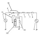
- FIG. 1 is a circuit diagram of a test apparatus for a direct current circuit breaker according to an embodiment of the present invention.
- the test apparatus according to the present embodiment includes a DC circuit breaker 1, a short circuit generator 2, a rectifier 3, reactors 4 and 5, a resistor 6, a closing switch 7, a protection circuit breaker 8, and a short circuit generator 9.
- the control part which performs those control is provided.
- the direct current circuit breaker 1 is a circuit breaker which interrupts direct current flowing in the direct current circuit breaker 1 in two different ways.
- the DC circuit breaker 1 includes a breaker 101 and an energy absorber 102.
- the blocking unit 101 and the energy absorbing unit 102 are provided in parallel.
- the shutoff unit 101 is a switch that shuts off / turns on the current flowing through the circuit.
- a mechanical switch or a semiconductor that mechanically shuts off / turns on can be used as the shutoff unit 101.
- the energy absorbing unit 102 is a so-called surge absorber (hereinafter, referred to as a surge absorber 102).
- the surge absorber 102 absorbs energy of transient high voltage applied to the surge absorber 102.
- the blocking unit 101 can limit the magnitude of the voltage after blocking.
- the DC circuit breaker 1 is connected to two different systems of a steady-state current supply system that supplies a steady-state current to the DC circuit breaker 1 and a fault current supply system that supplies a fault current.
- the steady-state current supply system includes a power supply for supplying a direct current to the DC circuit breaker 1
- the fault current supply system includes a power supply for supplying a fault current.
- the steady-state current supply system supplies direct current to the direct current circuit breaker.
- the steady state current supply system includes a short circuit generator 2, a rectifier 3, a reactor 4, and a resistor 6.
- a closing switch for connecting the short-circuit generator 2 to the test circuit and a protective circuit breaker for disconnecting are not shown.
- the short circuit generator 2 is a generator that generates a short circuit current.
- the short circuit current generated from the short circuit generator 2 is an alternating current.
- the short circuit current generated by the short circuit generator 2 is output to the rectifier 3.
- the rectifier 3 is a rectifier that rectifies the alternating current generated by the short circuit generator 2 into a direct current.
- the test apparatus is configured to function as an AC-DC converter.
- the direct current converted by the rectifier 3 is supplied to the DC circuit breaker 1 via the reactor 4 and the resistor 6.
- the fault current supply system supplies fault current to the DC circuit breaker 1.
- This fault current is an alternating current having a larger current than the direct current supplied from the steady-state current supply system to the DC circuit breaker 1.
- the fault current supply system includes a reactor 5, a closing switch 7, a protective breaker 8, and a short circuit generator 9.
- the short circuit generator 9 is a generator that generates a short circuit current.
- the short circuit generator 9 includes a high voltage power supply circuit as a comparison with the short circuit generator 2, and generates a fault current larger than the short circuit current generated in the short circuit generator 2.
- the short circuit current generated from the short circuit generator 9 is supplied to the DC circuit breaker 1 via the protection circuit breaker 8, the closing switch 7 and the reactor 5.
- the protective breaker 8 is a breaker that shuts off the fault current flowing through the fault current supply system by shutoff / turn-on. Cut off at the current zero point of the fault current flowing through the fault current supply system.
- the closing switch 7 is a switch which connects or disconnects the fault current supply system to the DC circuit breaker by breaking / closing.
- the operation of the testing apparatus of the direct current circuit breaker of the present embodiment thus configured will be described in detail with reference to FIGS.
- the test of the DC circuit breaker 1 is carried out by supplying the fault current from the fault current supply system to the DC circuit breaker 1 with the DC current supplied from the steady-state current system to the DC circuit breaker 1 Do.
- the detailed structure of the test of the direct current circuit breaker of this embodiment is demonstrated.
- FIG. 2 shows a current waveform in the process of interrupting the fault current by supplying the DC current and the fault current to the DC circuit breaker 1 from the start of the test.
- the direct current 10 is supplied from a power supply circuit for supplying a low voltage direct current, and flows through the blocking portion 101 of the direct current circuit breaker 1.
- the fault current 11 is supplied from a power supply circuit for supplying a high-pressure fault current and flows through the interrupting portion 101 of the DC breaker 1.
- the surge absorber current 12 is a current flowing to the surge absorber 102 after the shutoff portion 101 of the DC circuit breaker 1 is shut off.
- the short circuit generator 9 has a predetermined voltage excited in advance, and is separated from the DC circuit breaker 1 by the closing switch 7. As shown in FIG. 2, the direct current 10 is in a substantially steady state at time B on the time axis.
- fault current 11 is supplied to DC circuit breaker 1.
- the supply of the fault current 11 is performed by turning on the closing switch 7 in the cut-off state and connecting the fault current supply system to the DC circuit breaker 1 as shown in FIG.
- closing switch 7 is turned on at time point B of FIG. 2
- fault current 11 of a magnitude determined by the output voltage of short circuit generator 9 and reactor 5 is supplied to DC circuit breaker 1 and DC circuit breaker 1 is DC A current in which the fault current 11 is superimposed on the current 10 flows.
- the blocking portion 101 is opened to block the current.
- the surge absorber 102 operates by the voltage generated in the reactors 4 and 5.
- the fault current 11 supplied from the short circuit generator 9 flows to the surge absorber 102.
- a steady current 10 also flows to the surge absorber 102 from the steady current supply unit. That is, the surge absorber current 12 flowing to the surge absorber 102 is a current in which the steady current 10 and the fault current 11 are superimposed.
- the fault current 11 flowing to the surge absorber 102 is an alternating current whose magnitude is limited by the surge absorber 102. Therefore, it can be interrupted by the protection circuit breaker 8 at the current zero point.
- One of the current zeros of the fault current 11 is the point of time D in FIG.
- the protection circuit breaker 8 may cut off at the current zero point immediately after the point of time C.
- the fault current 11 does not flow to the stationary current supply system because it flows to the DC circuit breaker 1. Furthermore, even if the interrupting portion 101 is in an interrupting state, the fault current 11 flows to the surge absorber 102 and is interrupted by the protective interrupter 8 at the current zero point. As a result, the high voltage of the short circuit generator 9 is not applied to the low voltage power supply circuit.
- the DC system is divided into two systems: the power supply circuit that supplies a steady state DC current at low voltage and the power supply circuit that supplies only the fault current 11 at high voltage. It is possible to verify the interrupting performance of the DC circuit breaker at the time of failure occurrence in
- the power supply circuit for supplying the steady state current of the DC system does not need to apply a high voltage, and a rectifier with a rated voltage much lower than the recovery voltage applied to the DC circuit breaker
- the circuit can be configured by
- the circuit for supplying the fault current 11 only needs to supply the fault current 11, so there is no need to supply a direct current, and a fault occurs in the short circuit test facility comprising the short circuit generator, the closing switch, and the protective breaker.
- a current 11 can be supplied. Therefore, if a large power test facility for a common AC circuit breaker such as a short circuit generator is provided, it is possible to provide a test equipment for the DC circuit breaker without introducing an expensive large-scaled high voltage rectifier. It becomes.
- the direct current circuit breaker 1, the short circuit generator 2, the rectifier 3, the closing switch 7, the protection circuit breaker 8, and the short circuit generator 9 are used, the intention is to limit the scope of the invention. I did not.
- the rectifier 3 an AC-DC converter capable of converting AC current into DC current can be used.
Landscapes
- Physics & Mathematics (AREA)
- General Physics & Mathematics (AREA)
- Arc-Extinguishing Devices That Are Switches (AREA)
- Tests Of Circuit Breakers, Generators, And Electric Motors (AREA)
- Breakers (AREA)
- Testing Electric Properties And Detecting Electric Faults (AREA)
Abstract
大型化する高圧の整流器を導入することなく直流遮断器に対して試験が可能な試験装置及びその試験方法を提供するために、直流電流を遮断するための直流遮断器(1)の試験装置は、以下の構成を備える。(A)直流遮断器(1)に対して、直流電流を供給する定常電流供給系統。(B)直流遮断器(1)に対して、定常電流供給系統より供給される直流電流より大きな交流電流を供給する故障電流供給系統。(C)定常電流供給系統と、故障電流供給系統とは、直流遮断器(1)に対して異なる系統である。
Description
本発明の実施形態は、直流遮断器の遮断性能を検証するための試験装置及びその試験方法に関する。
交流を直流に変換する変換器は、サイリスタ等を用いた他励式と呼ばれる変換器が用いられ、直流送電が行われてきた。近年、PWM(Pulse Width Modulation)インバータ、コンバータ等を用いた自励式変換器の研究が行われている。
自励式変換器は定電圧制御されるため、直流系統で故障が発生すると、交流系統における故障のように、故障電流が増加する。直流系統を多端子構成にすると、交流系統で用いられている遮断器と同様に直流電流を遮断する遮断器が要求される。この直流遮断器も現在開発途上である。直流遮断器の開発にあたり、遮断性能を検証するためには実際の直流系統で想定される故障条件を模擬した条件で遮断試験を実施しなければならない。そのためには、直流系統での故障電流相当の電流を供給出来る試験装置が必要となる。
このようなものとして、英語文献、「JURGEN HAFNER, BJORN JACOBSON ” Proactive Hybrid HVDC Breaker - A key innovation for reliable HVDC grids” CIGRE International Symposium in Bologna, 2011」(以下、非特許文献1)がある。
JURGEN HAFNER, BJORN JACOBSON " Proactive Hybrid HVDCBreaker - A key innovation forreliable HVDC grids" CIGRE International Symposium in Bologna, 2011
上記自励式変換器を用いた直流送電における故障電流は、電源から故障点までの系統のインダクタンスと抵抗によって増加の時定数が決まる。非特許文献1では、故障電流を供給するために、電源回路にキャパシタCを挿入し、遮断器と直列にリアクトルLを配しており、直流電流と故障電流は共通の電源回路から供給される。故障電流を遮断後、直流遮断器の遮断部には所定の回復電圧が印加されなければならない。非特許文献1では、電源回路は共通であるため、直流電流を供給するために必要な整流器は回復電圧と同等の電圧で使用可能な高圧の整流器が必要となる。しかし、高圧の整流器を用いると試験装置の大型化、設備導入に高額な設備投資が必要といった課題がある。
本実施形態に係る直流遮断器の試験装置は、上記のような課題を解決するためになされたものであり、短絡発電機などの一般的な交流遮断器の大電力試験設備を有していれば、高額で大型化する高圧の整流器を導入することなく直流遮断器に対して試験が可能な試験装置及びその試験方法を提供する。
上記の目的を達成するために、本実施形態の直流電流を遮断するための直流遮断器の試験装置は、以下の構成を備える。
(1)前記直流遮断器に対して、直流電流を供給する定常電流供給部。
(2)前記直流遮断器に対して、前記定常電流供給部より供給される直流電流より大きな交流電流を供給する故障電流供給部。
(3)前記定常電流供給部と、前記故障電流供給部とは、前記直流遮断器に対して異なる系統に設けられる。
また、直流遮断器の試験方法も本発明の一態様である。
[第1の実施形態]
以下では、本実施形態の直流遮断器の試験装置及び試験方法について、図1乃至3を参照しつつ、説明する。なお、各図を通して同一部分には同一符号を付けることにより重複した説明は適宜省略する。
以下では、本実施形態の直流遮断器の試験装置及び試験方法について、図1乃至3を参照しつつ、説明する。なお、各図を通して同一部分には同一符号を付けることにより重複した説明は適宜省略する。
本実施形態の直流遮断器の試験装置は、試験対象となる直流遮断器に対して直流電流を供給する定常電流供給部と、定常電流供給部より供給される直流電流より大きな交流電流を供給する故障電流供給部と、を備える。この直流遮断器に対する試験では、以下の手順で試験を行う。
(1)試験開始時には、直流遮断器に対して定常電流供給部から定常電流を供給する。
(2)故障電流供給部の投入開閉部を投入し、故障電流を直流遮断器に対して供給する。
(3)直流遮断器の遮断部により電流を遮断すると共に、サージアブソーバにより、故障電流の大きさが制限される。
(4)制限された大きさの故障電流を故障電流供給部の保護遮断器により遮断する。
(5)定常電流をサージアブソーバにより減衰させる。
(全体構成)
図1は、本発明の実施形態に係る直流遮断器の試験装置の回路図である。本実施形態に係る試験装置は、直流遮断器1と、短絡発電機2、整流器3、リアクトル4,5、抵抗6、投入開閉器7、保護遮断器8、及び短絡発電機9を備える。また、試験装置を構成する直流遮断器1、短絡発電機2、投入開閉器7、保護遮断器8、及び短絡発電機9の状態を把握すると共に、それらの制御を行う制御部を備える。
図1は、本発明の実施形態に係る直流遮断器の試験装置の回路図である。本実施形態に係る試験装置は、直流遮断器1と、短絡発電機2、整流器3、リアクトル4,5、抵抗6、投入開閉器7、保護遮断器8、及び短絡発電機9を備える。また、試験装置を構成する直流遮断器1、短絡発電機2、投入開閉器7、保護遮断器8、及び短絡発電機9の状態を把握すると共に、それらの制御を行う制御部を備える。
直流遮断器1は、直流遮断器1内を流れる直流電流を2つの異なる方式で遮断する遮断器である。直流遮断器1は、遮断部101と、エネルギー吸収部102とを備える。遮断部101と、エネルギー吸収部102とは、並列に設けられる。
遮断部101は、回路を流れる電流の遮断/投入を行うスイッチである。遮断部101としては、例えば機械的に遮断/投入を行うメカニカルスイッチや半導体を利用することができる。
エネルギー吸収部102は、所謂サージアブソーバ(以下、サージアブソーバ102とする)である。サージアブソーバ102は、サージアブソーバ102に印加される過渡的な高電圧のエネルギーの吸収を行う。サージアブソーバ102により、遮断部101は、遮断後の電圧の大きさを制限することができる。
直流遮断器1には、直流遮断器1に対して、定常電流を供給する定常電流供給系統と、故障電流を供給する故障電流供給系統の2つの異なる系統が接続される。定常電流供給系統は、直流遮断器1に直流電流を供給するための電源を含み、故障電流供給系統は、故障電流供給用電源を含む。以下、本実施形態の直流遮断器の試験装置の詳細な構成について説明する。
(定常電流供給系統)
定常電流供給系統は、直流遮断器に対して直流電流を供給する。定常電流供給系統は、短絡発電機2、整流器3、リアクトル4、及び抵抗6を含む。短絡発電機2を試験回路に接続するための投入開閉器および切り離すための保護遮断器は図示していない。
定常電流供給系統は、直流遮断器に対して直流電流を供給する。定常電流供給系統は、短絡発電機2、整流器3、リアクトル4、及び抵抗6を含む。短絡発電機2を試験回路に接続するための投入開閉器および切り離すための保護遮断器は図示していない。
短絡発電機2は、短絡電流を発生させる発電機である。短絡発電機2から発生される短絡電流は交流の電流である。短絡発電機2で発生した短絡電流は、整流器3に対して出力される。
整流器3は、短絡発電機2で発生した交流電流を直流電流に整流する整流器である。試験装置においては、交流-直流変換部として機能するように構成される。整流器3で変換された直流電流は、リアクトル4及び抵抗6を介して、直流遮断器1に対して供給される。
(故障電流供給系統)
故障電流供給系統は、直流遮断器1に対して故障電流を供給する。この故障電流は、定常電流供給系統より直流遮断器1に対して供給される直流電流より大きな電流の交流電流である。故障電流供給系統は、リアクトル5、投入開閉器7、保護遮断器8、短絡発電機9を含む。
故障電流供給系統は、直流遮断器1に対して故障電流を供給する。この故障電流は、定常電流供給系統より直流遮断器1に対して供給される直流電流より大きな電流の交流電流である。故障電流供給系統は、リアクトル5、投入開閉器7、保護遮断器8、短絡発電機9を含む。
短絡発電機9は、短絡電流を発生させる発電機である。短絡発電機9は、短絡発電機2と比較として高圧の電源回路を備え、短絡発電機2で発生した短絡電流より大きな故障電流を発生する。短絡発電機9から発生した短絡電流は、保護遮断器8、投入開閉器7、リアクトル5を介して直流遮断器1に対して供給される。
保護遮断器8は、遮断/投入により、故障電流供給系統を流れる故障電流の遮断を行う遮断部である。故障電流供給系統を流れる故障電流の電流零点で遮断を行う。
投入開閉器7は、遮断/投入により、故障電流供給系統を直流遮断器に対して接続または離脱を行う開閉器である。
(作用)
このように構成された本実施形態の直流遮断器の試験装置の動作を図2乃至7を用いて詳述する。直流遮断器1の試験は、直流遮断器1に対して定常電流系統から直流電流を供給した状態で、更に直流遮断器1に対して故障電流供給系統から故障電流を供給することで試験を実施する。以下、本実施形態の直流遮断器の試験の詳細な構成について説明する。
このように構成された本実施形態の直流遮断器の試験装置の動作を図2乃至7を用いて詳述する。直流遮断器1の試験は、直流遮断器1に対して定常電流系統から直流電流を供給した状態で、更に直流遮断器1に対して故障電流供給系統から故障電流を供給することで試験を実施する。以下、本実施形態の直流遮断器の試験の詳細な構成について説明する。
図2は、試験開始から、直流遮断器1に直流電流及び故障電流が供給され、故障電流を遮断する過程における電流波形を示している。直流電流10は低圧の直流電流供給用の電源回路より供給され、直流遮断器1の遮断部101を流れる。故障電流11は高圧の故障電流供給用の電源回路より供給され直流遮断器1の遮断部101を流れる。また、サージアブソーバ電流12は直流遮断器1の遮断部101遮断後に、サージアブソーバ102に流れる電流である。
(1)試験開始時
試験開始時は、図3に示すように、直流遮断器1(遮断部101)及び保護遮断器8は閉路状態、投入開閉器7は開路状態とし、直流遮断器に対して定常電流供給部から定常電流を供給する。図2の時間軸のA時点において短絡発電機2を励磁し、短絡発電機2から供給された交流電流は整流器3により直流電流に変換される。整流器3から直流遮断器までに配されているリアクトル4、抵抗6、接続母線のインダクタンスによって決まる時定数で増加する直流電流10が直流遮断器1に供給される。
試験開始時は、図3に示すように、直流遮断器1(遮断部101)及び保護遮断器8は閉路状態、投入開閉器7は開路状態とし、直流遮断器に対して定常電流供給部から定常電流を供給する。図2の時間軸のA時点において短絡発電機2を励磁し、短絡発電機2から供給された交流電流は整流器3により直流電流に変換される。整流器3から直流遮断器までに配されているリアクトル4、抵抗6、接続母線のインダクタンスによって決まる時定数で増加する直流電流10が直流遮断器1に供給される。
一方、短絡発電機9はあらかじめ所定の電圧を励磁しておき、投入開閉器7によって直流遮断器1とは切り離されている。図2に示すように、直流電流10は時間軸のB時点においてほぼ定常状態となっている。
(2)故障電流の供給
次に、故障電流11を直流遮断器1に対して供給する。故障電流11の供給は、図4に示すように、遮断状態にある投入開閉器7を投入し、故障電流供給系統を直流遮断器1に対して接続することで行う。図2の時間軸B時点において投入開閉器7を投入すると、短絡発電機9の出力電圧とリアクトル5によって決まる大きさの故障電流11が直流遮断器1に供給され、直流遮断器1には直流電流10に故障電流11が重畳された電流が流れる。
次に、故障電流11を直流遮断器1に対して供給する。故障電流11の供給は、図4に示すように、遮断状態にある投入開閉器7を投入し、故障電流供給系統を直流遮断器1に対して接続することで行う。図2の時間軸B時点において投入開閉器7を投入すると、短絡発電機9の出力電圧とリアクトル5によって決まる大きさの故障電流11が直流遮断器1に供給され、直流遮断器1には直流電流10に故障電流11が重畳された電流が流れる。
(3)遮断部101の遮断
その後、図5に示すように遮断部101を開路し電流の遮断を行う。図2に示す時間軸のC時点で、遮断部101を開路することで、直流電流10および故障電流11が遮断されると、リアクトル4及び5に発生する電圧により、サージアブソーバ102が動作する。このため、短絡発電機9から供給される故障電流11は、サージアブソーバ102に流れる。同時に、定常電流供給部から定常電流10もサージアブソーバ102に流れる。すなわち、サージアブソーバ102に流れるサージアブソーバ電流12は、定常電流10と故障電流11とを重畳した電流である。
その後、図5に示すように遮断部101を開路し電流の遮断を行う。図2に示す時間軸のC時点で、遮断部101を開路することで、直流電流10および故障電流11が遮断されると、リアクトル4及び5に発生する電圧により、サージアブソーバ102が動作する。このため、短絡発電機9から供給される故障電流11は、サージアブソーバ102に流れる。同時に、定常電流供給部から定常電流10もサージアブソーバ102に流れる。すなわち、サージアブソーバ102に流れるサージアブソーバ電流12は、定常電流10と故障電流11とを重畳した電流である。
(4)故障電流の遮断
遮断部101の遮断後、サージアブソーバ102に短絡発電機9から供給される故障電流11が供給されると、図6に示すように、保護遮断器8を遮断状態とし故障電流11の遮断を行う。
遮断部101の遮断後、サージアブソーバ102に短絡発電機9から供給される故障電流11が供給されると、図6に示すように、保護遮断器8を遮断状態とし故障電流11の遮断を行う。
サージアブソーバ102に流れる故障電流11は、サージアブソーバ102で大きさが制限される交流電流である。そのため、電流零点で保護遮断器8によって遮断することができる。故障電流11の電流零点の一つは、図2におけるDの時点である。Cの時点直後の電流零点において保護遮断器8が遮断しても構わない。
故障電流の供給時には、故障電流11は、直流遮断器1に対して流れるため定常電流供給系統に対して流れることはない。さらに、遮断部101が遮断状態となっても、故障電流11は、サージアブソーバ102に対して流れ、電流零点で保護遮断器8によって遮断される。これにより、短絡発電機9の高電圧は、低圧の電源回路には印加されない。
(5)定常電流の減衰
図6に示すように、故障電流11の遮断後において、直流遮断器1に対して定常電流供給系統からは、直流電力が供給される。供給される直流電流10はサージアブソーバ102によって減衰し、図2におけるEの時点で零となる。
図6に示すように、故障電流11の遮断後において、直流遮断器1に対して定常電流供給系統からは、直流電力が供給される。供給される直流電流10はサージアブソーバ102によって減衰し、図2におけるEの時点で零となる。
以上のように、直流系統の故障発生時の電流を低圧で定常状態の直流電流を供給する電源回路と高圧で故障電流11のみを供給する電源回路の2系統に分けて供給することで直流系統での故障発生時の直流遮断器の遮断性能を検証することが出来る。
(効果)
(1)本実施形態によれば、直流系統の定常電流を供給する電源回路は、高電圧を印加する必要がなく、直流遮断器に印加される回復電圧に対して格段に低い定格電圧の整流器で回路を構成することが出来る。
(1)本実施形態によれば、直流系統の定常電流を供給する電源回路は、高電圧を印加する必要がなく、直流遮断器に印加される回復電圧に対して格段に低い定格電圧の整流器で回路を構成することが出来る。
(2)故障電流11を供給する回路は、故障電流11のみを供給すればよいので、直流電流を供給する必要がなく短絡発電機と投入開閉器、保護遮断器で構成する短絡試験設備で故障電流11を供給することが出来る。したがって、短絡発電機などの一般的な交流遮断器の大電力試験設備を有していれば、高額で大型化する高圧の整流器を導入することなく直流遮断器の試験装置を提供することが可能となる。
[その他の実施形態]
本明細書においては、本発明に係る複数の実施形態を説明したが、これらの実施形態は例として提示したものであって、発明の範囲を限定することを意図していない。具体的には、第1の実施形態は、その他の様々な形態で実施されることが可能であり、発明の範囲を逸脱しない範囲で、種々の省略や置き換え、変更を行うことができる。これらの実施形態やその変形は、発明の範囲や要旨に含まれると同様に、特許請求の範囲に記載された発明とその均等の範囲に含まれるものである。
本明細書においては、本発明に係る複数の実施形態を説明したが、これらの実施形態は例として提示したものであって、発明の範囲を限定することを意図していない。具体的には、第1の実施形態は、その他の様々な形態で実施されることが可能であり、発明の範囲を逸脱しない範囲で、種々の省略や置き換え、変更を行うことができる。これらの実施形態やその変形は、発明の範囲や要旨に含まれると同様に、特許請求の範囲に記載された発明とその均等の範囲に含まれるものである。
すなわち、第1の実施形態においては、直流遮断器1、短絡発電機2、整流器3、投入開閉器7、保護遮断器8、短絡発電機9としたが、発明の範囲を限定することを意図していない。例えば、整流器3としては、交流電流を直流電流に変換することが可能な交流-直流変換部を使用することもできる。
1 直流遮断器
101 遮断部
102 サージアブソーバ
2 短絡発電機
3 整流器
4,5 リアクトル
6 抵抗
7 投入開閉器
8 保護遮断器
9 短絡発電機
10 直流電流
11 故障電流
12 サージアブソーバ電流
101 遮断部
102 サージアブソーバ
2 短絡発電機
3 整流器
4,5 リアクトル
6 抵抗
7 投入開閉器
8 保護遮断器
9 短絡発電機
10 直流電流
11 故障電流
12 サージアブソーバ電流
Claims (6)
- 直流電流を遮断するための直流遮断器の試験装置において、
前記直流遮断器に対して、直流電流を供給する定常電流供給部と、
前記直流遮断器に対して、前記定常電流供給部より供給される直流電流より大きな交流電流を供給する故障電流供給部と、
を備え、
前記定常電流供給部と、前記故障電流供給部とは、前記直流遮断器に対して異なる系統に設けられる直流遮断器の試験装置。 - 前記定常電流供給部は、
交流電流を発生する第1の短絡発電部と、
前記第1の短絡発電部で発生した交流電流を、直流電流に変換する交流/直流変換部と、
を備える請求項1に記載の直流遮断器の試験装置。 - 前記故障電流供給部は、
交流電流を発生する第2の短絡発電部と、
電流の遮断及び投入を行う投入開閉部と、
を備える請求項1または請求項2に記載の直流遮断器の試験装置。 - 前記故障電流供給部は、更に、
保護遮断器を備える請求項3に記載の直流遮断器の試験装置。 - 直流電流を遮断するための直流遮断器の試験方法において、
前記直流遮断器に対して、前記電力系統が定常状態で流れる大きさの直流電流を供給する定常電流供給部処理と、
前記直流遮断器に対して、前記電力系統に異常が発生した際に流れる故障電流を供給する故障電流供給処理と、
を含み、
前記定常電流と前記故障電流は、前記直流遮断器に対して異なる系統により供給される直流遮断器の試験方法。 - 前記故障電流供給処理は、前記定常電流供給部処理と並行して行われ、
前記定常電流と前記故障電流とが重畳した電流が、前記直流遮断器に流れる請求項5に記載の直流遮断器の試験方法。
Priority Applications (2)
| Application Number | Priority Date | Filing Date | Title |
|---|---|---|---|
| EP14844247.8A EP3046127A4 (en) | 2013-09-13 | 2014-09-09 | Device for testing dc circuit breaker and testing method therefor |
| CN201480050059.XA CN105531787A (zh) | 2013-09-13 | 2014-09-09 | 直流断路器的试验装置及其试验方法 |
Applications Claiming Priority (2)
| Application Number | Priority Date | Filing Date | Title |
|---|---|---|---|
| JP2013191144A JP2015056389A (ja) | 2013-09-13 | 2013-09-13 | 直流遮断器の試験装置及びその試験方法 |
| JP2013-191144 | 2013-09-13 |
Publications (1)
| Publication Number | Publication Date |
|---|---|
| WO2015037223A1 true WO2015037223A1 (ja) | 2015-03-19 |
Family
ID=52665354
Family Applications (1)
| Application Number | Title | Priority Date | Filing Date |
|---|---|---|---|
| PCT/JP2014/004622 Ceased WO2015037223A1 (ja) | 2013-09-13 | 2014-09-09 | 直流遮断器の試験装置及びその試験方法 |
Country Status (4)
| Country | Link |
|---|---|
| EP (1) | EP3046127A4 (ja) |
| JP (1) | JP2015056389A (ja) |
| CN (1) | CN105531787A (ja) |
| WO (1) | WO2015037223A1 (ja) |
Cited By (3)
| Publication number | Priority date | Publication date | Assignee | Title |
|---|---|---|---|---|
| CN108535645A (zh) * | 2018-04-24 | 2018-09-14 | 国网湖北省电力有限公司电力科学研究院 | 一种柱上断路器保护功能一二次融合试验方法 |
| EP3315980A4 (en) * | 2015-06-26 | 2019-02-20 | Kabushiki Kaisha Toshiba, Inc. | TEST PROCEDURE FOR DC CIRCUIT BREAKERS |
| CN109633361A (zh) * | 2019-01-14 | 2019-04-16 | 上海交通大学 | 中压直流发电机出口短路故障稳态电流检测方法 |
Families Citing this family (6)
| Publication number | Priority date | Publication date | Assignee | Title |
|---|---|---|---|---|
| WO2018042516A1 (ja) * | 2016-08-30 | 2018-03-08 | 株式会社 東芝 | 機械式開閉器の試験方法及びその試験装置 |
| EP3557268B1 (en) * | 2016-12-15 | 2023-05-17 | Toshiba Energy Systems & Solutions Corporation | Testing apparatus for dc circuit breaker |
| CN108957303B (zh) * | 2017-05-26 | 2020-08-25 | 许继电气股份有限公司 | 一种高压直流断路器电流耐受试验回路及方法 |
| CN107526030A (zh) * | 2017-07-05 | 2017-12-29 | 全球能源互联网研究院 | 一种高压直流断路器的合成试验装置和方法 |
| CN107424864A (zh) * | 2017-08-23 | 2017-12-01 | 中科电力装备集团有限公司 | 一种高压开关设备的断路器 |
| CN109061450B (zh) * | 2018-06-19 | 2021-02-09 | 北京平高清大科技发展有限公司 | 一种直流断路器用机械开关的试验电路 |
Citations (4)
| Publication number | Priority date | Publication date | Assignee | Title |
|---|---|---|---|---|
| JPS5927417A (ja) * | 1982-08-04 | 1984-02-13 | 株式会社東芝 | 直流しや断器の試験方法 |
| JPH11341706A (ja) * | 1998-03-05 | 1999-12-10 | Toshiba Corp | 制御システム、電力系統保護制御システムおよびプログラムを記憶した記憶媒体 |
| JP2003115242A (ja) * | 2001-10-03 | 2003-04-18 | Toshiba Corp | 遮断器試験回路 |
| JP2010008226A (ja) * | 2008-06-26 | 2010-01-14 | Chugoku Electric Power Co Inc:The | 遮断器試験装置および遮断器試験方法 |
Family Cites Families (3)
| Publication number | Priority date | Publication date | Assignee | Title |
|---|---|---|---|---|
| DE2408229A1 (de) * | 1974-02-21 | 1975-09-04 | Licentia Gmbh | Schaltanordnung fuer lichtbogenuntersuchungen |
| DE19930993A1 (de) * | 1999-07-05 | 2001-01-11 | Asea Brown Boveri | Prüfkreis für die synthetische Prüfung des Einschaltvermögens von Hochspannungsschaltgeräten |
| CN102288905B (zh) * | 2011-06-27 | 2014-07-02 | 中国西电电气股份有限公司 | 一种用于高压交流断路器的合成关合试验线路 |
-
2013
- 2013-09-13 JP JP2013191144A patent/JP2015056389A/ja active Pending
-
2014
- 2014-09-09 CN CN201480050059.XA patent/CN105531787A/zh active Pending
- 2014-09-09 EP EP14844247.8A patent/EP3046127A4/en not_active Withdrawn
- 2014-09-09 WO PCT/JP2014/004622 patent/WO2015037223A1/ja not_active Ceased
Patent Citations (4)
| Publication number | Priority date | Publication date | Assignee | Title |
|---|---|---|---|---|
| JPS5927417A (ja) * | 1982-08-04 | 1984-02-13 | 株式会社東芝 | 直流しや断器の試験方法 |
| JPH11341706A (ja) * | 1998-03-05 | 1999-12-10 | Toshiba Corp | 制御システム、電力系統保護制御システムおよびプログラムを記憶した記憶媒体 |
| JP2003115242A (ja) * | 2001-10-03 | 2003-04-18 | Toshiba Corp | 遮断器試験回路 |
| JP2010008226A (ja) * | 2008-06-26 | 2010-01-14 | Chugoku Electric Power Co Inc:The | 遮断器試験装置および遮断器試験方法 |
Non-Patent Citations (2)
| Title |
|---|
| JURGEN HAFNER; BJORN JACOBSON: "Proactive Hybrid HVDC Breaker - A key innovation for reliable HVDC grids", CIGRE INTERNATIONAL SYMPOSIUM IN BOLOGNA, 2011 |
| See also references of EP3046127A4 * |
Cited By (4)
| Publication number | Priority date | Publication date | Assignee | Title |
|---|---|---|---|---|
| EP3315980A4 (en) * | 2015-06-26 | 2019-02-20 | Kabushiki Kaisha Toshiba, Inc. | TEST PROCEDURE FOR DC CIRCUIT BREAKERS |
| CN108535645A (zh) * | 2018-04-24 | 2018-09-14 | 国网湖北省电力有限公司电力科学研究院 | 一种柱上断路器保护功能一二次融合试验方法 |
| CN108535645B (zh) * | 2018-04-24 | 2019-08-09 | 国网湖北省电力有限公司电力科学研究院 | 一种柱上断路器保护功能一二次融合试验方法 |
| CN109633361A (zh) * | 2019-01-14 | 2019-04-16 | 上海交通大学 | 中压直流发电机出口短路故障稳态电流检测方法 |
Also Published As
| Publication number | Publication date |
|---|---|
| EP3046127A4 (en) | 2017-01-25 |
| EP3046127A1 (en) | 2016-07-20 |
| JP2015056389A (ja) | 2015-03-23 |
| CN105531787A (zh) | 2016-04-27 |
Similar Documents
| Publication | Publication Date | Title |
|---|---|---|
| WO2015037223A1 (ja) | 直流遮断器の試験装置及びその試験方法 | |
| US12132303B2 (en) | DC circuit breaker with an alternating commutating circuit | |
| WO2015040862A1 (ja) | 直流遮断器の試験装置及び直流遮断器の試験装置による試験方法 | |
| JP6109649B2 (ja) | 直流電流遮断装置 | |
| WO2015121983A1 (ja) | 直流送電系統の保護システムおよび交流/直流変換器ならびに直流送電系統の遮断方法 | |
| JP6645758B2 (ja) | 直流遮断器の試験方法 | |
| CN105409079A (zh) | 限流电抗器装置 | |
| Cwikowski et al. | Analysis and simulation of the proactive hybrid circuit breaker | |
| Karthikeyan et al. | Simulation and analysis of faults in high voltage DC (HVDC) power transmission | |
| JP6767644B2 (ja) | 直流遮断器の試験装置 | |
| EP3197042A1 (en) | Wind power generation system and dc power feeding system | |
| Liu et al. | Protection of single-phase fault at the transformer valve side of FB-MMC-based bipolar HVdc systems | |
| Jakka et al. | Protection design considerations of a 10 kV SiC MOSFET enabled mobile utilities support equipment based solid state transformer (muse-SST) | |
| EP2798713B1 (en) | System for reducing overvoltage damage | |
| JP2016213123A (ja) | 直流遮断器の試験装置及びその試験方法 | |
| WO2018042516A1 (ja) | 機械式開閉器の試験方法及びその試験装置 | |
| CN207304421U (zh) | 一种带限流电阻的无触点有载自动调压系统 | |
| Yu et al. | Design and analysis of a peak current-limiting device using an oscillating zero-crossing circuit | |
| Kim et al. | Protection coordination in DC shipboard power systems: challenges, current status and new technologies | |
| KR101759595B1 (ko) | Ac선로와 dc선로가 병가된 송전선로의 선간 접촉 보호 시스템 | |
| Lin et al. | Hardware-in-the-loop implementation of a hybrid circuit breaker controller for MMC-based HVDC systems | |
| Chen et al. | The power plant arrester configuration and modeling of insulation coordination | |
| KR20190132061A (ko) | 한류 퓨즈와 써지 흡수 장치를 사용한 직류용 전력변환용 반도체 소자의 보호장치 | |
| Yanushkevich | HVDC circuit breakers modeling in multiterminal grids | |
| WO2018146748A1 (ja) | 直流遮断器の試験装置及び試験方法 |
Legal Events
| Date | Code | Title | Description |
|---|---|---|---|
| WWE | Wipo information: entry into national phase |
Ref document number: 201480050059.X Country of ref document: CN |
|
| 121 | Ep: the epo has been informed by wipo that ep was designated in this application |
Ref document number: 14844247 Country of ref document: EP Kind code of ref document: A1 |
|
| REEP | Request for entry into the european phase |
Ref document number: 2014844247 Country of ref document: EP |
|
| WWE | Wipo information: entry into national phase |
Ref document number: 2014844247 Country of ref document: EP |
|
| NENP | Non-entry into the national phase |
Ref country code: DE |