WO2015037251A1 - 空気調和装置 - Google Patents
空気調和装置 Download PDFInfo
- Publication number
- WO2015037251A1 WO2015037251A1 PCT/JP2014/051165 JP2014051165W WO2015037251A1 WO 2015037251 A1 WO2015037251 A1 WO 2015037251A1 JP 2014051165 W JP2014051165 W JP 2014051165W WO 2015037251 A1 WO2015037251 A1 WO 2015037251A1
- Authority
- WO
- WIPO (PCT)
- Prior art keywords
- indoor
- defrosting operation
- compressor
- refrigerant
- unit
- Prior art date
- Legal status (The legal status is an assumption and is not a legal conclusion. Google has not performed a legal analysis and makes no representation as to the accuracy of the status listed.)
- Ceased
Links
Images
Classifications
-
- F—MECHANICAL ENGINEERING; LIGHTING; HEATING; WEAPONS; BLASTING
- F25—REFRIGERATION OR COOLING; COMBINED HEATING AND REFRIGERATION SYSTEMS; HEAT PUMP SYSTEMS; MANUFACTURE OR STORAGE OF ICE; LIQUEFACTION SOLIDIFICATION OF GASES
- F25B—REFRIGERATION MACHINES, PLANTS OR SYSTEMS; COMBINED HEATING AND REFRIGERATION SYSTEMS; HEAT PUMP SYSTEMS
- F25B47/00—Arrangements for preventing or removing deposits or corrosion, not provided for in another subclass
- F25B47/02—Defrosting cycles
- F25B47/022—Defrosting cycles hot gas defrosting
- F25B47/025—Defrosting cycles hot gas defrosting by reversing the cycle
-
- F—MECHANICAL ENGINEERING; LIGHTING; HEATING; WEAPONS; BLASTING
- F24—HEATING; RANGES; VENTILATING
- F24F—AIR-CONDITIONING; AIR-HUMIDIFICATION; VENTILATION; USE OF AIR CURRENTS FOR SCREENING
- F24F11/00—Control or safety arrangements
- F24F11/70—Control systems characterised by their outputs; Constructional details thereof
-
- F—MECHANICAL ENGINEERING; LIGHTING; HEATING; WEAPONS; BLASTING
- F24—HEATING; RANGES; VENTILATING
- F24F—AIR-CONDITIONING; AIR-HUMIDIFICATION; VENTILATION; USE OF AIR CURRENTS FOR SCREENING
- F24F3/00—Air-conditioning systems in which conditioned primary air is supplied from one or more central stations to distributing units in the rooms or spaces where it may receive secondary treatment; Apparatus specially designed for such systems
- F24F3/06—Air-conditioning systems in which conditioned primary air is supplied from one or more central stations to distributing units in the rooms or spaces where it may receive secondary treatment; Apparatus specially designed for such systems characterised by the arrangements for the supply of heat-exchange fluid for the subsequent treatment of primary air in the room units
- F24F3/065—Air-conditioning systems in which conditioned primary air is supplied from one or more central stations to distributing units in the rooms or spaces where it may receive secondary treatment; Apparatus specially designed for such systems characterised by the arrangements for the supply of heat-exchange fluid for the subsequent treatment of primary air in the room units with a plurality of evaporators or condensers
-
- F—MECHANICAL ENGINEERING; LIGHTING; HEATING; WEAPONS; BLASTING
- F25—REFRIGERATION OR COOLING; COMBINED HEATING AND REFRIGERATION SYSTEMS; HEAT PUMP SYSTEMS; MANUFACTURE OR STORAGE OF ICE; LIQUEFACTION SOLIDIFICATION OF GASES
- F25B—REFRIGERATION MACHINES, PLANTS OR SYSTEMS; COMBINED HEATING AND REFRIGERATION SYSTEMS; HEAT PUMP SYSTEMS
- F25B49/00—Arrangement or mounting of control or safety devices
- F25B49/02—Arrangement or mounting of control or safety devices for compression type machines, plants or systems
-
- F—MECHANICAL ENGINEERING; LIGHTING; HEATING; WEAPONS; BLASTING
- F24—HEATING; RANGES; VENTILATING
- F24F—AIR-CONDITIONING; AIR-HUMIDIFICATION; VENTILATION; USE OF AIR CURRENTS FOR SCREENING
- F24F11/00—Control or safety arrangements
- F24F11/30—Control or safety arrangements for purposes related to the operation of the system, e.g. for safety or monitoring
- F24F11/41—Defrosting; Preventing freezing
- F24F11/42—Defrosting; Preventing freezing of outdoor units
-
- F—MECHANICAL ENGINEERING; LIGHTING; HEATING; WEAPONS; BLASTING
- F24—HEATING; RANGES; VENTILATING
- F24F—AIR-CONDITIONING; AIR-HUMIDIFICATION; VENTILATION; USE OF AIR CURRENTS FOR SCREENING
- F24F11/00—Control or safety arrangements
- F24F11/62—Control or safety arrangements characterised by the type of control or by internal processing, e.g. using fuzzy logic, adaptive control or estimation of values
- F24F11/63—Electronic processing
- F24F11/64—Electronic processing using pre-stored data
-
- F—MECHANICAL ENGINEERING; LIGHTING; HEATING; WEAPONS; BLASTING
- F24—HEATING; RANGES; VENTILATING
- F24F—AIR-CONDITIONING; AIR-HUMIDIFICATION; VENTILATION; USE OF AIR CURRENTS FOR SCREENING
- F24F11/00—Control or safety arrangements
- F24F11/70—Control systems characterised by their outputs; Constructional details thereof
- F24F11/80—Control systems characterised by their outputs; Constructional details thereof for controlling the temperature of the supplied air
- F24F11/83—Control systems characterised by their outputs; Constructional details thereof for controlling the temperature of the supplied air by controlling the supply of heat-exchange fluids to heat-exchangers
- F24F11/85—Control systems characterised by their outputs; Constructional details thereof for controlling the temperature of the supplied air by controlling the supply of heat-exchange fluids to heat-exchangers using variable-flow pumps
-
- F—MECHANICAL ENGINEERING; LIGHTING; HEATING; WEAPONS; BLASTING
- F25—REFRIGERATION OR COOLING; COMBINED HEATING AND REFRIGERATION SYSTEMS; HEAT PUMP SYSTEMS; MANUFACTURE OR STORAGE OF ICE; LIQUEFACTION SOLIDIFICATION OF GASES
- F25B—REFRIGERATION MACHINES, PLANTS OR SYSTEMS; COMBINED HEATING AND REFRIGERATION SYSTEMS; HEAT PUMP SYSTEMS
- F25B2313/00—Compression machines, plants or systems with reversible cycle not otherwise provided for
- F25B2313/006—Compression machines, plants or systems with reversible cycle not otherwise provided for two pipes connecting the outdoor side to the indoor side with multiple indoor units
-
- F—MECHANICAL ENGINEERING; LIGHTING; HEATING; WEAPONS; BLASTING
- F25—REFRIGERATION OR COOLING; COMBINED HEATING AND REFRIGERATION SYSTEMS; HEAT PUMP SYSTEMS; MANUFACTURE OR STORAGE OF ICE; LIQUEFACTION SOLIDIFICATION OF GASES
- F25B—REFRIGERATION MACHINES, PLANTS OR SYSTEMS; COMBINED HEATING AND REFRIGERATION SYSTEMS; HEAT PUMP SYSTEMS
- F25B2313/00—Compression machines, plants or systems with reversible cycle not otherwise provided for
- F25B2313/023—Compression machines, plants or systems with reversible cycle not otherwise provided for using multiple indoor units
- F25B2313/0233—Compression machines, plants or systems with reversible cycle not otherwise provided for using multiple indoor units in parallel arrangements
-
- F—MECHANICAL ENGINEERING; LIGHTING; HEATING; WEAPONS; BLASTING
- F25—REFRIGERATION OR COOLING; COMBINED HEATING AND REFRIGERATION SYSTEMS; HEAT PUMP SYSTEMS; MANUFACTURE OR STORAGE OF ICE; LIQUEFACTION SOLIDIFICATION OF GASES
- F25B—REFRIGERATION MACHINES, PLANTS OR SYSTEMS; COMBINED HEATING AND REFRIGERATION SYSTEMS; HEAT PUMP SYSTEMS
- F25B2313/00—Compression machines, plants or systems with reversible cycle not otherwise provided for
- F25B2313/029—Control issues
- F25B2313/0293—Control issues related to the indoor fan, e.g. controlling speed
-
- F—MECHANICAL ENGINEERING; LIGHTING; HEATING; WEAPONS; BLASTING
- F25—REFRIGERATION OR COOLING; COMBINED HEATING AND REFRIGERATION SYSTEMS; HEAT PUMP SYSTEMS; MANUFACTURE OR STORAGE OF ICE; LIQUEFACTION SOLIDIFICATION OF GASES
- F25B—REFRIGERATION MACHINES, PLANTS OR SYSTEMS; COMBINED HEATING AND REFRIGERATION SYSTEMS; HEAT PUMP SYSTEMS
- F25B2313/00—Compression machines, plants or systems with reversible cycle not otherwise provided for
- F25B2313/029—Control issues
- F25B2313/0294—Control issues related to the outdoor fan, e.g. controlling speed
-
- F—MECHANICAL ENGINEERING; LIGHTING; HEATING; WEAPONS; BLASTING
- F25—REFRIGERATION OR COOLING; COMBINED HEATING AND REFRIGERATION SYSTEMS; HEAT PUMP SYSTEMS; MANUFACTURE OR STORAGE OF ICE; LIQUEFACTION SOLIDIFICATION OF GASES
- F25B—REFRIGERATION MACHINES, PLANTS OR SYSTEMS; COMBINED HEATING AND REFRIGERATION SYSTEMS; HEAT PUMP SYSTEMS
- F25B2313/00—Compression machines, plants or systems with reversible cycle not otherwise provided for
- F25B2313/031—Sensor arrangements
- F25B2313/0314—Temperature sensors near the indoor heat exchanger
-
- F—MECHANICAL ENGINEERING; LIGHTING; HEATING; WEAPONS; BLASTING
- F25—REFRIGERATION OR COOLING; COMBINED HEATING AND REFRIGERATION SYSTEMS; HEAT PUMP SYSTEMS; MANUFACTURE OR STORAGE OF ICE; LIQUEFACTION SOLIDIFICATION OF GASES
- F25B—REFRIGERATION MACHINES, PLANTS OR SYSTEMS; COMBINED HEATING AND REFRIGERATION SYSTEMS; HEAT PUMP SYSTEMS
- F25B2313/00—Compression machines, plants or systems with reversible cycle not otherwise provided for
- F25B2313/031—Sensor arrangements
- F25B2313/0315—Temperature sensors near the outdoor heat exchanger
-
- F—MECHANICAL ENGINEERING; LIGHTING; HEATING; WEAPONS; BLASTING
- F25—REFRIGERATION OR COOLING; COMBINED HEATING AND REFRIGERATION SYSTEMS; HEAT PUMP SYSTEMS; MANUFACTURE OR STORAGE OF ICE; LIQUEFACTION SOLIDIFICATION OF GASES
- F25B—REFRIGERATION MACHINES, PLANTS OR SYSTEMS; COMBINED HEATING AND REFRIGERATION SYSTEMS; HEAT PUMP SYSTEMS
- F25B2600/00—Control issues
- F25B2600/02—Compressor control
- F25B2600/025—Compressor control by controlling speed
-
- F—MECHANICAL ENGINEERING; LIGHTING; HEATING; WEAPONS; BLASTING
- F25—REFRIGERATION OR COOLING; COMBINED HEATING AND REFRIGERATION SYSTEMS; HEAT PUMP SYSTEMS; MANUFACTURE OR STORAGE OF ICE; LIQUEFACTION SOLIDIFICATION OF GASES
- F25B—REFRIGERATION MACHINES, PLANTS OR SYSTEMS; COMBINED HEATING AND REFRIGERATION SYSTEMS; HEAT PUMP SYSTEMS
- F25B2700/00—Sensing or detecting of parameters; Sensors therefor
- F25B2700/19—Pressures
- F25B2700/193—Pressures of the compressor
- F25B2700/1931—Discharge pressures
-
- F—MECHANICAL ENGINEERING; LIGHTING; HEATING; WEAPONS; BLASTING
- F25—REFRIGERATION OR COOLING; COMBINED HEATING AND REFRIGERATION SYSTEMS; HEAT PUMP SYSTEMS; MANUFACTURE OR STORAGE OF ICE; LIQUEFACTION SOLIDIFICATION OF GASES
- F25B—REFRIGERATION MACHINES, PLANTS OR SYSTEMS; COMBINED HEATING AND REFRIGERATION SYSTEMS; HEAT PUMP SYSTEMS
- F25B2700/00—Sensing or detecting of parameters; Sensors therefor
- F25B2700/19—Pressures
- F25B2700/193—Pressures of the compressor
- F25B2700/1933—Suction pressures
-
- F—MECHANICAL ENGINEERING; LIGHTING; HEATING; WEAPONS; BLASTING
- F25—REFRIGERATION OR COOLING; COMBINED HEATING AND REFRIGERATION SYSTEMS; HEAT PUMP SYSTEMS; MANUFACTURE OR STORAGE OF ICE; LIQUEFACTION SOLIDIFICATION OF GASES
- F25B—REFRIGERATION MACHINES, PLANTS OR SYSTEMS; COMBINED HEATING AND REFRIGERATION SYSTEMS; HEAT PUMP SYSTEMS
- F25B2700/00—Sensing or detecting of parameters; Sensors therefor
- F25B2700/21—Temperatures
- F25B2700/2115—Temperatures of a compressor or the drive means therefor
- F25B2700/21151—Temperatures of a compressor or the drive means therefor at the suction side of the compressor
-
- F—MECHANICAL ENGINEERING; LIGHTING; HEATING; WEAPONS; BLASTING
- F25—REFRIGERATION OR COOLING; COMBINED HEATING AND REFRIGERATION SYSTEMS; HEAT PUMP SYSTEMS; MANUFACTURE OR STORAGE OF ICE; LIQUEFACTION SOLIDIFICATION OF GASES
- F25B—REFRIGERATION MACHINES, PLANTS OR SYSTEMS; COMBINED HEATING AND REFRIGERATION SYSTEMS; HEAT PUMP SYSTEMS
- F25B2700/00—Sensing or detecting of parameters; Sensors therefor
- F25B2700/21—Temperatures
- F25B2700/2115—Temperatures of a compressor or the drive means therefor
- F25B2700/21152—Temperatures of a compressor or the drive means therefor at the discharge side of the compressor
Definitions
- the present invention relates to an air conditioner in which at least one outdoor unit and at least one indoor unit are connected to each other through a plurality of refrigerant pipes.
- an air conditioner in which at least one outdoor unit and at least one indoor unit are connected to each other through a plurality of refrigerant pipes has been proposed.
- the outdoor heat exchanger When the air conditioner is performing a heating operation, the outdoor heat exchanger may be frosted if the temperature of the outdoor heat exchanger becomes 0 ° C. or lower.
- frost is formed on the outdoor heat exchanger, ventilation to the outdoor heat exchanger is hindered by the frost, and the heat exchange efficiency in the outdoor heat exchanger may be reduced. Therefore, if frost formation occurs in the outdoor heat exchanger, it is necessary to perform a defrosting operation in order to remove the frost from the outdoor heat exchanger.
- an air conditioner described in Patent Document 1 includes a single outdoor unit including a compressor, a four-way valve, an outdoor heat exchanger, and an outdoor fan, an indoor heat exchanger, and an indoor expansion valve that is a flow control valve. And two indoor units including an indoor fan are connected by a gas refrigerant pipe and a liquid refrigerant pipe.
- the defrosting operation is performed during the heating operation, the rotation of the outdoor fan and the indoor fan is stopped, the compressor is once stopped, and the outdoor heat exchanger is used as an evaporator.
- the four-way valve is switched so that the functioning state changes from the functioning state to the state of functioning as a condenser, and the compressor is started again.
- the outdoor heat exchanger By causing the outdoor heat exchanger to function as a condenser, the high-temperature refrigerant discharged from the compressor flows into the outdoor heat exchanger and melts frost adhering to the outdoor heat exchanger. Thereby, defrosting of an outdoor heat exchanger can be performed.
- the compressor When performing the defrosting operation, it is preferable to increase the rotation speed of the compressor as much as possible.
- the defrosting operation is performed at a higher compressor speed, the amount of high-temperature refrigerant that is discharged from the compressor and flows into the outdoor heat exchanger increases. It is because it can be returned to.
- the compressor is started at a predetermined high rotation speed (for example, 90 rps, hereinafter referred to as the start-up rotation speed).
- the pull-down that occurs at the start of the defrosting operation will be described.
- the compressor is once stopped, and after switching the four-way valve, the compressor is restarted.
- the four-way valve is switched, one port on the indoor heat exchanger side of the indoor expansion valve connected to the discharge side of the compressor during heating operation is connected to the suction side of the compressor, and the other side of the indoor expansion valve The pressure difference from the port becomes smaller.
- the pressure difference between the two ports of the indoor expansion valve increases as time elapses from the start of the compressor, and the refrigerant does not flow into the gas refrigerant pipe from the indoor unit unless the pressure difference exceeds a predetermined value. Therefore, at the time of starting the compressor, after the refrigerant staying in the location near the suction side of the compressor in the gas refrigerant pipe is sucked, the amount of refrigerant staying in the gas refrigerant pipe is temporarily reduced, and the compressor A so-called pull-down occurs in which the suction pressure of the water drops rapidly. In addition, the lowering of the suction pressure due to pull-down increases as the rotational speed at the start of the compressor increases.
- the outdoor heat exchanger functions as a condenser so that the high-temperature refrigerant discharged from the compressor flows into the outdoor heat exchanger to melt the generated frost.
- the amount of frost formation becomes a frost formation amount according to the size of the outdoor heat exchanger, and the larger the outdoor heat exchanger, the larger the frost formation amount. Therefore, when the outdoor heat exchanger is large, it is necessary to flow more high-temperature refrigerant to the outdoor heat exchanger than when the outdoor heat exchanger is small.
- the indoor heat exchanger that functions as an evaporator during the defrosting operation is sized according to the rated capacity of the indoor unit, and an indoor expansion valve having a capacity corresponding to the size of the indoor heat exchanger is provided.
- the capacity of the indoor expansion valve is the amount of refrigerant that passes through the indoor expansion valve per unit time when the indoor expansion valve is fully opened.
- the smaller the indoor heat exchanger the smaller the capacity of the indoor expansion valve. Is used. Therefore, when the indoor heat exchanger is small, an indoor expansion valve with a smaller capacity is used than when the indoor heat exchanger is large, so the amount of refrigerant that can pass through the indoor expansion valve, that is, from the indoor unit to the gas refrigerant piping.
- the amount of refrigerant flowing out decreases.
- the refrigerant stays in the outdoor heat exchanger or the liquid refrigerant pipe and the refrigerant circulation amount in the air conditioner decreases, and the lower the refrigerant circulation amount, the greater the degree of decrease in the suction pressure.
- the suction pressure may be further reduced due to a pull-down that occurs when the compressor is started, and may fall below the lower limit of performance. If the suction pressure falls below the lower limit of performance, the compressor may be damaged, and low pressure protection control is performed to stop the compressor 21 so that the compressor 21 is not damaged, and the defrosting operation time is long. There was a problem that the return to heating operation was delayed.
- the present invention solves the above-described problems.
- the compressor By performing the defrosting operation control according to the capacity of the indoor expansion valve, that is, the rated capacity of the indoor unit, the compressor is damaged or the heating operation is delayed. It aims at providing the air conditioning apparatus which prevents.
- an air conditioner of the present invention includes at least one outdoor unit having a compressor, a flow path switching unit, an outdoor heat exchanger, and an outdoor unit control unit, and an indoor heat exchanger. And at least one indoor unit having a flow rate adjustment valve, at least one liquid pipe and at least one gas pipe connecting the outdoor unit and the indoor unit. Then, the outdoor unit control means drives the compressor at a starting rotational speed that is a predetermined value for a predetermined time after the start of the defrosting operation, and this starting rotational speed is the sum of the capacities of the flow control valves. A plurality of values are determined accordingly.
- the rotational speed at the start of the compressor at the start of the defrosting operation has a plurality of values determined according to the total capacity of the flow rate adjusting valve and the refrigerant pipe length which is the length of the liquid pipe and the gas pipe. It is what.
- the compressor is started at a starting rotational speed corresponding to the sum of the capacities of the flow rate adjusting valves for a predetermined time after starting the defrosting operation, or at a flow rate. It is driven at the starting rotational speed corresponding to the total capacity of the regulating valve and the refrigerant pipe length.
- the low pressure protection control can be prevented from being executed when the suction pressure falls below the compressor performance lower limit suction pressure, the defrost operation is interrupted by the low pressure protection control, and the defrosting operation time becomes longer. There is no delay in returning to operation.
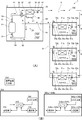
- (A) is a refrigerant circuit figure
- (B) is a block diagram of an outdoor unit control means and an indoor unit control means. It is a defrost operation condition table in the embodiment of the present invention. It is a flowchart explaining the process at the time of a defrost driving
- an air conditioning apparatus will be described as an example in which three indoor units are connected in parallel to one outdoor unit, and cooling operation or heating operation can be performed simultaneously in all indoor units.
- the present invention is not limited to the following embodiments, and can be variously modified without departing from the gist of the present invention.
- an air conditioner 1 in this embodiment is connected to one outdoor unit 2 installed outdoors and in parallel to the outdoor unit 2 through a liquid pipe 8 and a gas pipe 9.
- Three indoor units 5a to 5c are provided.
- the liquid pipe 8 has one end connected to the closing valve 25 of the outdoor unit 2 and the other end branched to be connected to the liquid pipe connecting portions 53a to 53c of the indoor units 5a to 5c.
- the gas pipe 9 has one end connected to the closing valve 26 of the outdoor unit 2 and the other end branched to be connected to the gas pipe connecting portions 54a to 54c of the indoor units 5a to 5c.
- the refrigerant circuit 100 of the air conditioner 1 is configured as described above.
- the outdoor unit 2 includes a compressor 21, a four-way valve 22 which is a flow path switching unit, an outdoor heat exchanger 23, an outdoor expansion valve 24, a closing valve 25 to which one end of the liquid pipe 8 is connected, a gas pipe 9 is provided with a shut-off valve 26 to which one end of 9 is connected and an outdoor fan 27.
- These devices other than the outdoor fan 27 are connected to each other through refrigerant pipes described in detail below to constitute an outdoor unit refrigerant circuit 20 that forms part of the refrigerant circuit 100.
- the compressor 21 is a variable capacity compressor capable of changing the operation capacity by being driven by a motor (not shown) whose rotation speed is controlled by an inverter.
- the refrigerant discharge side of the compressor 21 is connected to a port a of a four-way valve 22 which will be described later by a discharge pipe 41, and the refrigerant suction side of the compressor 21 is connected to a port c of the four-way valve 22 which will be described later. Connected with.
- the four-way valve 22 is a valve for switching the direction in which the refrigerant flows, and has four ports a, b, c, and d.
- the port a is connected to the refrigerant discharge side of the compressor 21 by the discharge pipe 41 as described above.
- the port b is connected to one refrigerant inlet / outlet of the outdoor heat exchanger 23 by a refrigerant pipe 43.
- the port c is connected to the refrigerant suction side of the compressor 21 by the suction pipe 42 as described above.
- the port d is connected to the closing valve 26 by an outdoor unit gas pipe 45.
- the outdoor heat exchanger 23 exchanges heat between the refrigerant and the outside air taken into the outdoor unit 2 by the rotation of the outdoor fan 27 described later.
- one refrigerant inlet / outlet of the outdoor heat exchanger 23 is connected to the port b of the four-way valve 22 by the refrigerant pipe 43, and the other refrigerant inlet / outlet is connected to the closing valve 25 by the outdoor unit liquid pipe 44.
- the outdoor expansion valve 24 is provided in the outdoor unit liquid pipe 44.
- the outdoor expansion valve 24 is an electronic expansion valve, and the amount of refrigerant flowing into the outdoor heat exchanger 23 or the amount of refrigerant flowing out of the outdoor heat exchanger 23 is adjusted by adjusting the opening thereof.
- the outdoor fan 27 is formed of a resin material and is disposed in the vicinity of the outdoor heat exchanger 23.
- the outdoor fan 27 is rotated by a fan motor (not shown) to take outside air into the outdoor unit 2 from a suction port (not shown), and the outdoor air exchanged heat with the refrigerant in the outdoor heat exchanger 23 from the blower outlet (not shown) to the outside of the outdoor unit 2. To release.
- a discharge pipe 41 includes a high-pressure sensor 31 that detects the pressure of refrigerant discharged from the compressor 21, and a discharge temperature sensor that detects the temperature of refrigerant discharged from the compressor 21. 33 is provided.
- the suction pipe 42 is provided with a low pressure sensor 32 that detects the pressure of the refrigerant sucked into the compressor 21 and a suction temperature sensor 34 that detects the temperature of the refrigerant sucked into the compressor 21.
- the outdoor heat exchanger 23 is provided with a heat exchange temperature sensor 35 for detecting frost formation during heating operation or melting of frost during defrost operation.
- An outdoor air temperature sensor 36 that detects the temperature of the outside air flowing into the outdoor unit 2, that is, the outside air temperature, is provided near a suction port (not shown) of the outdoor unit 2.
- the outdoor unit 2 is provided with an outdoor unit control means 200.
- the outdoor unit control means 200 is mounted on a control board stored in an electrical component box (not shown) of the outdoor unit 2.
- the outdoor unit control means 200 includes a CPU 210, a storage unit 220, a communication unit 230, and a sensor input unit 240.
- the storage unit 220 includes a ROM and a RAM, and includes detection values corresponding to control programs for the outdoor unit 2 and detection signals from various sensors, control states of the compressor 21 and the outdoor fan 27, and defrosting operation conditions described later. Stores tables, etc.
- the communication unit 230 is an interface for performing communication with the indoor units 5a to 5c.
- the sensor input unit 240 captures detection results from various sensors of the outdoor unit 2 and outputs them to the CPU 210.
- CPU210 takes in the detection result in each sensor of outdoor unit 2 mentioned above via sensor input part 240.
- FIG. the CPU 210 takes in control signals transmitted from the indoor units 5a to 5c via the communication unit 230.
- the CPU 210 performs drive control of the compressor 21 and the outdoor fan 27 based on the detection results and control signals taken in.
- the CPU 210 performs switching control of the four-way valve 22 based on the detection results and control signals taken in.
- the CPU 210 controls the opening degree of the outdoor expansion valve 24 based on the acquired detection result and control signal.
- the outdoor unit 2 is provided with an installation information input unit 250.
- the installation information input unit 250 is disposed, for example, on the side surface of the casing of the outdoor unit 2 (not shown) and can be operated from the outside.
- the installation information input unit 250 includes a setting button, a determination button, and a display unit.
- the setting button is composed of, for example, a numeric keypad, and is used to input information related to a refrigerant pipe length (the length of the liquid pipe 8 and the gas pipe 9), which will be described later, and a flow coefficient Cv of each of the indoor expansion valves 52a to 52c. .
- the decision button is for confirming information input by the setting button.
- the display unit displays various input information, current operation information of the outdoor unit 2, and the like.
- the installation information input unit 250 is not limited to the above.
- the setting button may be a dip switch or a dial switch.
- the three indoor units 5a to 5c include indoor heat exchangers 51a to 51c, indoor expansion valves 52a to 52c that are flow rate adjusting valves, and liquid pipe connection portions 53a to 53c to which the other ends of the branched liquid pipes 8 are connected. 53c, gas pipe connection portions 54a to 54c to which the other ends of the branched gas pipes 9 are connected, and indoor fans 55a to 55c. These devices other than the indoor fans 55a to 55c are connected to each other through refrigerant pipes that will be described in detail below, thereby constituting indoor unit refrigerant circuits 50a to 50c that form part of the refrigerant circuit 100.
- the indoor heat exchanger 51a exchanges heat between the refrigerant and indoor air taken into the indoor unit 5a from a suction port (not shown) by an indoor fan 55a, which will be described later.
- the other refrigerant inlet / outlet port is connected to the gas pipe connecting portion 54a via the indoor unit gas pipe 72a.
- the indoor heat exchanger 51a functions as an evaporator when the indoor unit 5a performs a cooling operation, and functions as a condenser when the indoor unit 5a performs a heating operation.
- the indoor heat exchanger 51a is sized according to the rated capacity of the indoor unit 5a. Note that the refrigerant pipes of the liquid pipe connecting part 53a and the gas pipe connecting part 54a are connected by welding, flare nuts, or the like.
- the indoor expansion valve 52a is provided in the indoor unit liquid pipe 71a.
- the indoor expansion valve 52a is an electronic expansion valve having a capacity corresponding to the size of the indoor heat exchanger 51a, and the amount of refrigerant flowing through the indoor heat exchanger 51a can be adjusted by adjusting the opening degree.
- the indoor expansion valve 52a is adjusted according to the required cooling capacity, and when the indoor heat exchanger 51a functions as a condenser, The opening is adjusted according to the required heating capacity.
- the capacity of the indoor expansion valve 52a is the amount of refrigerant that passes through the indoor expansion valve 52a per unit time when the indoor expansion valve 52a is fully opened.
- the indoor fan 55a is formed of a resin material and is disposed in the vicinity of the indoor heat exchanger 51a.
- the indoor fan 55a is rotated by a fan motor (not shown) to take indoor air into the indoor unit 5a from a suction port (not shown), and the indoor air exchanged with the refrigerant in the indoor heat exchanger 51a from the blower outlet (not shown) to the room. To supply.
- the indoor unit 5a is provided with various sensors. Between the indoor heat exchanger 51a and the indoor expansion valve 52a in the indoor unit liquid pipe 71a, a liquid side temperature sensor 61a that detects the temperature of the refrigerant flowing into or out of the indoor heat exchanger 51a. Is provided.
- the indoor unit gas pipe 72a is provided with a gas side temperature sensor 62a that detects the temperature of the refrigerant flowing out of the indoor heat exchanger 51a or flowing into the indoor heat exchanger 51a.
- An indoor temperature sensor 63a that detects the temperature of the indoor air flowing into the indoor unit 5a, that is, the indoor temperature, is provided in the vicinity of a suction port (not shown) of the indoor unit 5a.
- the indoor unit 5a is provided with an indoor unit control means 500a.
- the indoor unit control means 500a is mounted on a control board stored in an electrical component box (not shown) of the indoor unit 5a.
- a CPU 510a As shown in FIG. 1B, a CPU 510a, a storage unit 520a, a communication unit 530a, And a sensor input unit 540a.
- the storage unit 520a is configured by a ROM or a RAM, and stores a detection value corresponding to a control program of the indoor unit 5a and detection signals from various sensors, setting information related to an air conditioning operation by the user, and the like.
- the communication unit 530a is an interface for communicating with the outdoor unit 2 and the other indoor units 5b and 5c.
- the sensor input unit 540a captures detection results from various sensors of the indoor unit 5a and outputs them to the CPU 510a.
- the CPU 510a takes in the detection result of each sensor of the indoor unit 5a described above via the sensor input unit 540a. Further, the CPU 510a takes in a signal including operation information set by operating a remote controller (not shown), a timer operation setting, and the like via a remote control light receiving unit (not shown). The CPU 510a performs the opening degree control of the indoor expansion valve 52a and the drive control of the indoor fan 55a based on the acquired detection result and the signal transmitted from the remote controller. In addition, the CPU 510a transmits a control signal including an operation start / stop signal and operation information (set temperature, indoor temperature, etc.) to the outdoor unit 2 via the communication unit 530a.
- the outdoor unit control means 200 is in a state where the four-way valve 22 is indicated by a solid line, that is, the ports a and b of the four-way valve 22 Are switched so as to communicate with each other and port c and port d communicate with each other.
- the outdoor heat exchanger 23 functions as a condenser
- the indoor heat exchangers 51a to 51c function as evaporators.
- the high-pressure refrigerant discharged from the compressor 21 flows through the discharge pipe 41 and flows into the four-way valve 22, and flows from the four-way valve 22 through the refrigerant pipe 43 and flows into the outdoor heat exchanger 23.
- the refrigerant flowing into the outdoor heat exchanger 23 is condensed by exchanging heat with the outside air taken into the outdoor unit 2 by the rotation of the outdoor fan 27.
- the refrigerant flowing out of the outdoor heat exchanger 23 flows through the outdoor unit liquid pipe 44 and flows into the liquid pipe 8 through the outdoor expansion valve 24 and the closing valve 25 that are fully opened.
- the refrigerant flowing through the liquid pipe 8 and diverted into the indoor units 5a to 5c flows through the indoor unit liquid pipes 71a to 71c and is reduced in pressure to pass through the indoor expansion valves 52a to 52c to become low-pressure refrigerant.
- the refrigerant flowing into the indoor heat exchangers 51a to 51c from the indoor unit liquid tubes 71a to 71c evaporates by exchanging heat with the indoor air taken into the indoor units 5a to 5c by the rotation of the indoor fans 55a to 55c.
- the indoor heat exchangers 51a to 51c function as evaporators, and the indoor air that has exchanged heat with the refrigerant in the indoor heat exchangers 51a to 51c is blown into the room from a blower outlet (not shown), thereby The room where the machines 5a to 5c are installed is cooled.
- the refrigerant flowing out of the indoor heat exchangers 51 a to 51 c flows through the indoor unit gas pipes 72 a to 72 c and flows into the gas pipe 9.
- the refrigerant flowing through the gas pipe 9 and flowing into the outdoor unit 2 through the closing valve 26 flows through the outdoor unit gas pipe 45, the four-way valve 22, and the suction pipe 42, and is sucked into the compressor 21 and compressed again.
- the cooling operation of the air conditioner 1 is performed by circulating the refrigerant through the refrigerant circuit 100.
- the outdoor unit control means 200 is configured so that the four-way valve 22 is indicated by a broken line, that is, the port a and the port d of the four-way valve 22 communicate with each other. Switch so that port b and port c communicate.
- the outdoor heat exchanger 23 functions as an evaporator
- the indoor heat exchangers 51a to 51c function as condensers.
- the heating operation time (the time when the air conditioning apparatus 1 is started in the heating operation or the time when the heating operation is continued from the time when the defrosting operation is returned to the heating operation) is 30 minutes. After a lapse of time, when the refrigerant temperature detected by the heat exchange temperature sensor 35 is lower by 5 ° C. or more than the outside air temperature detected by the outside air temperature sensor 36 for 10 minutes or more, or when the previous defrosting operation is completed.
- the predetermined time (example: 180 minutes) has passed since, it is shown that the amount of frost formation in the outdoor heat exchanger 23 is at a level that hinders the heating capacity.
- the outdoor unit control means 200 stops the compressor 21 and stops the heating operation, switches the refrigerant circuit 100 to the state during the cooling operation described above, and sets the compressor 21 to a predetermined state.
- the defrosting operation is started by restarting at the number of revolutions. Note that when the defrosting operation is performed, the outdoor fan 27 and the indoor fans 55a to 55c are stopped, but the other operations of the refrigerant circuit 100 are the same as those during the cooling operation. The detailed explanation is omitted.
- the outdoor unit control means 200 stops the compressor 21 to stop the defrosting operation, and after switching the refrigerant circuit 100 to the heating operation state, The heating operation is restarted by starting at a rotational speed corresponding to the heating capacity required for the indoor units 5a to 5c.
- the defrosting operation end condition is, for example, whether or not the temperature of the refrigerant flowing out from the outdoor heat exchanger 23 detected by the heat exchanger temperature sensor 35 has become 10 ° C. or more, and a predetermined time ( For example, whether or not 10 minutes) has elapsed, etc., and the frost generated in the outdoor heat exchanger 23 is considered to be melted.
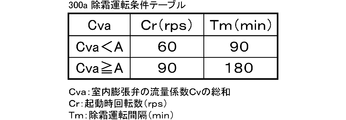
- the defrosting operation condition table 300a shown in FIG. 2 is stored in advance in the storage unit 220 provided in the outdoor unit control unit 200 of the outdoor unit 2.
- the defrosting operation condition table 300a indicates the rotation speed Cr (unit: rps) of the compressor 21 when the air-conditioning apparatus 1 starts the defrosting operation and the defrosting operation interval Tm (unit: min). This is determined according to the flow coefficient sum Cva which is the sum of the flow coefficients Cv of the indoor expansion valves 52a to 52c.
- the flow coefficient Cv of the indoor expansion valves 52a to 52c represents the capacity of the indoor expansion valves 52a to 52c, the difference in the structure and dimensions of the indoor expansion valves 52a to 52c, the indoor expansion valves 52a to 52c, and so on.
- the capacity of each of the indoor expansion valves 52a to 52c can be represented regardless of the difference in physical properties such as the pressure difference between the two ports and the temperature, viscosity, specific gravity, etc. of the refrigerant flowing through the refrigerant circuit 100.
- the flow coefficient Cv is determined by using the specific gravity of the refrigerant, the flow rate of the refrigerant flowing through the indoor expansion valves 52a to 52c per unit time, and the pressures at both ports of the indoor expansion valves 52a to 52c.
- the threshold value A, the startup rotation speed Cr, and the defrosting operation interval Tm in FIG. 2 are numerical values determined in advance by a test or the like, and are values unique to the air conditioner 1.
- the air conditioning apparatus 1 performs the defrosting operation, it is necessary to switch the refrigerant circuit 100 from the heating operation state to the defrosting (cooling) operation state. And the compressor 21 is restarted after switching the four-way valve 22.
- the four-way valve 22 is switched, the ports on the indoor heat exchangers 51a to 51c side of the indoor expansion valves 52a to 52c connected to the discharge side of the compressor 21 during the heating operation are connected to the suction side of the compressor 21.
- the pressure difference between the indoor expansion valves 52a to 52c and the liquid pipe connecting portions 53a to 53c is reduced.
- the above-described pressure difference increases as time elapses from the start of the compressor 21, and the refrigerant does not flow into the gas pipe 9 from the indoor units 5a to 5c unless the pressure difference exceeds a predetermined value. Therefore, when the compressor 21 is started, after the refrigerant staying in the gas pipe 9 near the suction side of the compressor 21 is sucked into the compressor 21, the amount of refrigerant staying in the gas pipe 9 is temporarily reduced. As a result, the so-called pull-down in which the suction pressure of the compressor 21 rapidly decreases occurs.
- the outdoor heat exchanger 23 functions as a condenser, so that the high-temperature refrigerant discharged from the compressor 21 flows into the outdoor heat exchanger 23 and melts the frost that has formed.
- the amount of frost formation in the heat exchanger 23 becomes the amount of frost formation according to the magnitude
- the indoor heat exchangers 51a to 51c functioning as evaporators during the defrosting operation include an indoor expansion valve 52a having a capacity (flow coefficient Cv) corresponding to the size of the indoor heat exchangers 51a to 51c.
- the indoor expansion valves 52a to 52c having a smaller flow coefficient Cv are used as the indoor heat exchangers 51a to 51c are smaller. Therefore, when the indoor heat exchangers 51a to 51c are small, the indoor expansion valves 52a to 52c having a smaller flow coefficient Cv are used than when the indoor heat exchangers 51a to 51c are large.
- the amount of refrigerant that can pass through that is, the amount of refrigerant flowing out from the indoor units 5a to 5c to the gas pipe 9 is reduced.
- the refrigerant circulation amount of the refrigerant circuit 100 at the start of the defrosting operation depends on the flow coefficient sum Cva which is the sum of the flow coefficients Cv of the indoor expansion valves 52a to 52c, and the smaller the flow coefficient sum Cva,
- the amount of refrigerant flowing out of the indoor heat exchangers 51a to 51c is smaller than the amount of refrigerant flowing into the outdoor heat exchanger 23, and the refrigerant stagnates in the outdoor heat exchanger 23 and the liquid pipe 8, so that the amount of refrigerant circulating under the installation conditions Less.
- the refrigerant circulation amount in the installation conditions decreases, the degree of decrease in the suction pressure increases.
- the compressor 21 is started by increasing the starting rotation speed Cr of the compressor 21 (90 rps) in order to start the defrosting operation in a state where the suction pressure is greatly reduced due to the flow rate coefficient sum Cva, There is a possibility that the suction pressure is further lowered by the pulled-down and falls below the lower limit of performance. If the suction pressure falls below the lower limit of performance, the compressor 21 may be damaged, or low pressure protection control for stopping the compressor 21 is executed so that the compressor 21 is not damaged, and the defrosting operation time becomes longer. There is a fear.
- the rotation speed Cr at the start-up of the compressor 21 is set.
- the defrosting operation is performed while preventing the suction pressure from dropping and falling below the lower limit of performance.
- the total flow coefficient Cva is equal to or greater than the threshold value A, the degree of decrease in the suction pressure is small and the possibility that the suction pressure falls below the lower limit of performance is small. Control is performed so that the defrosting operation is completed as soon as possible.
- the defrosting operation interval Tm is an interval time during which the defrosting operation start condition is not satisfied during the heating operation, and the time when the defrosting operation interval Tm has elapsed from the time of returning to the heating operation. In order to forcibly execute the defrosting operation, it is determined.
- the defrosting operation start condition when the defrosting operation start condition is satisfied, the amount of frost formation in the outdoor heat exchanger 23 is such that the heating capacity is hindered. On the other hand, even if the defrosting operation start condition is not satisfied, the amount is smaller than that in the case where the defrosting operation start condition is satisfied. There is a possibility that the heat exchange efficiency in the heat exchanger 23 may be reduced, and even a small amount of frost is preferably removed from the outdoor heat exchanger 23. Therefore, even if the defrosting operation interval Tm is determined and the defrosting operation start condition is not satisfied, the defrosting operation is performed when the defrosting operation interval Tm has elapsed since the end of the previous defrosting operation. The frost generated in the outdoor heat exchanger 23 is melted.
- the ability to melt the frost formed on the outdoor heat exchanger 23 per unit time during the defrosting operation (hereinafter referred to as “defrosting ability”) is higher as the rotational speed of the compressor 21 is higher. Since the amount of high-temperature and high-pressure refrigerant flowing into the vessel 23 increases, it increases.
- the defrosting operation is started with the starting rotation speed Cr being set to 60 rps. In this case, the starting rotation speed Cr is set to 90 rps. Compared with the case where the frost operation is started, the defrosting capability is lowered, and the defrosting operation time is also increased accordingly.
- the defrosting operation time becomes longer.
- the defrosting operation interval Tm is set to 90 min, and the outdoor heat exchanger 23 is installed.
- the defrosting operation is performed before the amount of frost increases.
- the frequency of switching to the defrosting operation is increased as compared with the case where the defrosting operation interval Tm is set to 180 min, the defrosting operation is started as much as possible by starting the defrosting operation before the amount of frosting increases. This is done so that the comfort of the user during heating operation is not impaired.
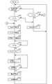
- FIG. 3 shows a flow of processing performed by the CPU 210 of the outdoor unit control unit 200 when the air conditioning apparatus 1 performs the defrosting operation.
- ST represents a step
- the number following this represents a step number.
- FIG. 3 mainly describes the processing related to the present invention, and other processing, for example, air conditioning such as control of the refrigerant circuit corresponding to the operating conditions such as the set temperature and the air volume instructed by the user. Description of general processing related to the apparatus is omitted.
- the air conditioner 1 stores the flow coefficient Cv of each of the indoor expansion valves 52a to 52c input from the setting information input unit 250 in the storage unit 220 as an initial setting at the time of installation.
- CP U210 calculates the flow coefficient sum Cva by adding the stored flow coefficient Cv of each of the indoor expansion valves 52a to 52c.
- CPU210 refers to the defrost operation condition table 300a memorize
- the CPU 210 determines whether or not the defrosting operation start condition is satisfied (ST1).
- the defrosting operation start condition is, for example, that the refrigerant temperature detected by the heat exchange temperature sensor 35 is lower by 5 ° C. or more than the outside air temperature detected by the outside air temperature sensor 36 after 30 minutes of the heating operation time has elapsed. This is a case where the state continues for 10 minutes or more, and the CPU 210 takes in the refrigerant temperature detected by the heat exchange temperature sensor 35 and the outside air temperature detected by the outside air temperature sensor 36 and determines whether or not the above condition is satisfied.
- the CPU 210 reads the defrosting operation interval Tm stored in the storage unit 220, and the duration time Ts of the heating operation is the defrosting operation interval. It is determined whether it is less than Tm (ST12). If the duration time Ts of the heating operation is not less than the defrosting operation interval Tm (ST12-No), the CPU 210 advances the process to ST3. If the duration time Ts of the heating operation is less than the defrosting operation interval Tm (ST12-Yes), the CPU 210 continues the heating operation (ST13) and returns the process to ST1.
- the CPU 210 determines whether the duration time Ts of the heating operation is equal to or longer than the heating mask time Th (ST2).
- the heating mask time Th is a time for continuing the heating operation without switching to the defrosting operation even if the defrosting operation start condition is satisfied again after returning from the defrosting operation to the heating operation. It is provided so that the user's comfort is not impaired by frequently switching to the defrosting operation.
- This heating mask time is set to 40 minutes, for example.
- the CPU 210 advances the process to ST13, continues the heating operation, and returns the process to ST1. If the duration time Ts of the heating operation is equal to or longer than the heating mask time Th (ST2-Yes), the CPU 210 advances the process to ST3.
- the CPU 210 executes a defrosting operation preparation process.
- the CPU 210 stops the compressor 21 and the outdoor fan 27 and switches the ports a and b to communicate with each other and the ports c and d to communicate with each other in the four-way valve 22.
- the outdoor heat exchanger 23 functions as a condenser and the indoor heat exchangers 51a to 51c function as evaporators, that is, when the cooling operation shown in FIG. 1 (A) is performed. It becomes a state.
- the CPUs 510a to 510c of the indoor units 5a to 5c stop the indoor fans 55a to 55c.
- the CPU 210 starts timer measurement (ST4), and starts the compressor 21 at the starting rotation speed Cr stored in the storage unit 220 (ST5). By starting the compressor 21, the air-conditioning apparatus 1 starts the defrosting operation.
- the CPU 210 includes a timer measuring unit.
- the CPU 210 determines whether or not one minute has elapsed after starting the timer measurement in ST5, that is, starting the compressor 21 (ST6). If one minute has not elapsed (ST6-No), the CPU 210 returns to ST6, and if one minute has elapsed (ST6-Yes), the CPU 210 resets the timer (ST7).
- the processes from ST4 to ST7 described above are performed for 1 minute after the compressor 21 is started in order to drive the compressor 21 while maintaining the rotational speed of the compressor 21 at the starting rotational speed Cr.
- the starting rotational speed Cr is determined according to the flow coefficient sum Cva, and if the compressor 21 is started at the starting rotational speed Cr at the start of the defrosting operation, the suction due to pull-down is performed. A decrease in pressure can be suppressed. This pull-down is eliminated when the pressure difference between the two ports of the indoor expansion valves 52a to 52c becomes a predetermined value or more and the refrigerant flows into the gas pipe 9 from the indoor units 5a to 5c.
- a predetermined time is required after the compressor 21 is started. Accordingly, it is desirable that the rotation speed of the compressor 21 is not changed during this predetermined time, and maintained at the startup rotation speed Cr.
- the predetermined time is determined in advance by experiments or the like.
- CPU210 which reset the timer by ST7 makes the rotation speed of the compressor 21 the predetermined rotation speed (for example, 90 rps) (ST8).
- the predetermined number of revolutions is obtained in advance by a test or the like and stored in the storage unit 220.
- the CPU 210 determines whether or not the defrosting operation termination condition is satisfied (ST9).
- the defrosting operation end condition is, for example, whether or not the temperature of the refrigerant flowing out of the outdoor heat exchanger 23 detected by the heat exchange temperature sensor 35 has become 10 ° C. or higher.
- the CPU 210 always takes in the refrigerant temperature detected by the heat exchange temperature sensor 35 and stores it in the storage unit 220.
- the CPU 210 refers to the stored refrigerant temperature, and determines whether or not the temperature is 10 ° C. or higher, that is, whether or not the defrosting operation end condition is satisfied.
- the defrosting operation end condition is determined in advance by a test or the like, and is a condition that the frost generated in the outdoor heat exchanger 23 is considered to have melted.
- the CPU 210 In ST9, if the defrosting operation termination condition is not satisfied (ST9-No), the CPU 210 returns the process to ST8 and continues the defrosting operation. If the defrosting operation termination condition is satisfied (ST9-Yes), CPU 210 executes the heating operation resuming process (ST10). In the operation restart process, the CPU 210 stops the compressor 21 and switches the four-way valve 22 so that the ports a and d communicate with each other and the ports b and c communicate with each other. As a result, the refrigerant circuit 100 enters a state in which the outdoor heat exchanger 23 functions as an evaporator and the indoor heat exchangers 51a to 51c function as condensers.
- the CPU210 restarts heating operation (ST11) and returns a process to ST1.
- the CPU 210 controls the rotation speed of the compressor 21 and the outdoor fan 27 and the opening degree of the outdoor expansion valve 24 according to the heating capacity required from the indoor units 5a to 5c.
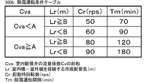
- the defrosting operation condition table 300c includes the starting rotation speed Cr of the compressor 21 and the defrosting operation interval Tm when the air conditioner 1 starts the defrosting operation, the flow coefficient sum Cva, the refrigerant pipe length Lr, It is determined according to.
- the refrigerant pipe length Lr indicates the length (unit: m) of the liquid pipe 8 and the gas pipe 9, and in the present embodiment, the maximum value of the refrigerant pipe length Lr will be described as 50 m.
- the refrigerant pipe length Lr is determined according to the size of the building where the air conditioner 1 is installed and the distance from the place where the outdoor unit 2 is installed to the room where the indoor units 5a to 5c are installed.
- the refrigerant pipe length Lr is input from the setting information input unit 250 at the initial setting when the air conditioner 1 is installed, like the flow coefficient Cv of each of the indoor expansion valves 52a to 52c described in the first embodiment. .
- the flow coefficient sum Cva is less than a predetermined threshold A (for example, 0.4) or more than the threshold A (for this, the defrosting operation is performed).
- a predetermined threshold A for example, 0.4
- the threshold A for this, the defrosting operation is performed.
- a defrosting operation interval Tm is defined for each of the condition table 300a.
- the starting rotation speed Cr is 50 rps and the defrosting operation interval Tm is 70 min.
- the startup rotation speed Cr is 60 rps and the defrosting operation interval Tm is 90 min.
- the starting rotation speed Cr is 80 rps and the defrosting operation interval Tm is 120 min.
- the threshold value A, the threshold pipe length B, the startup rotation speed Cr, and the defrosting operation interval Tm in FIG. 4 are numerical values determined in advance by a test or the like, and are unique values in the air conditioner 1. .
- the reason why the rotation speed Cr and the defrosting operation interval Tm of the compressor 21 are determined according to the flow coefficient sum Cva and the refrigerant pipe length Lr in the defrosting operation condition table 300b will be described.
- the liquid pipe connection parts 53a to 53c side (high pressure side) of the indoor expansion valves 52a to 52c and the indoor heat exchangers 51a to 51c side (low pressure side) ) The refrigerant does not flow into the gas pipe 9 from the indoor units 5a to 5c, the amount of refrigerant staying in the gas pipe 9 is temporarily reduced, and the suction pressure of the compressor 21 suddenly increases. Decreasing pull-down occurs.
- the degree of decrease in suction pressure when pull-down occurs increases as the refrigerant pipe length Lr increases. This is because the longer the liquid pipe 8 is, the more difficult the pressure on the connecting portions 53a to 53c side of the indoor expansion valves 52a to 52c increases due to the pressure loss in the liquid pipe 8, and therefore the pressure difference between the indoor expansion valves 52a to 52c. This is because it takes a long time until the refrigerant flowing into the gas pipe 9 from the indoor units 5a to 5c is sucked into the compressor 21.
- the possibility that the suction pressure is lower than the lower limit of performance is higher when the refrigerant pipe length Lr is longer than when the refrigerant pipe length Lr is short.
- the total flow coefficient Cva is large, there is a higher possibility that the suction pressure is lower than the lower limit of performance when the refrigerant pipe length Lr is long compared to when the refrigerant pipe length Lr is short.
- the defrosting operation condition table 300b that determines the starting rotation speed Cr of the compressor 21 according to the flow coefficient sum Cva and the refrigerant pipe length Lr is provided.
- the starting rotation speed Cr of the compressor 21 is determined based on the defrosting operation condition table 300b.
- the defrosting operation interval Tm is determined according to the starting rotation speed Cr of the compressor 21 as in the first embodiment, and depends on the starting rotation speed Cr of the compressor 21. The effects of the differences are also the same as those in the first embodiment, and a description thereof will be omitted.
- the air-conditioning apparatus of the present invention is configured so that the compressor is operated at the starting rotational speed corresponding to the flow coefficient or the flow coefficient and the refrigerant pipe length for a predetermined time after the start of the defrosting operation. Drives at the corresponding starting rotation speed.
- the suction pressure is greatly reduced and falls below the compressor performance lower limit pressure. Can be prevented. Therefore, breakage of the compressor can be prevented.
- the low pressure protection control can be prevented from being executed when the suction pressure falls below the compressor performance lower limit suction pressure, the defrost operation is interrupted by the low pressure protection control, and the defrosting operation time becomes longer. There is no delay in returning to operation.
- the flow coefficient Cv of each of the indoor expansion valves 52a to 52c has been described for the case where the operator manually inputs the flow rate coefficient Cv by operating the installation information input unit 250 when installing the air conditioner.
- the flow coefficient Cv of each of the indoor expansion valves 52a to 52c is included in the model information related to the indoor units 5a to 5c stored in the storage units 520a to 520c of the indoor unit control units 500a to 500c.
- the CPU 210 of the outdoor unit 2 may acquire the flow coefficient Cv of each of the indoor expansion valves 52a to 52c by taking this model information from the indoor units 5a to 5c.
- the model information is basic information of the indoor units 5a to 5c such as the rated capacity, model name, identification number, etc. of the indoor units 5a to 5c, in addition to the flow coefficient Cv of each of the indoor expansion valves 52a to 52c. It is comprised by.
- the present invention is not limited to this, and the pressure difference between the ports of the indoor expansion valves 52a to 52c and the indoor expansion valve 52a are not limited thereto.
- the Kv value or the Av value obtained by making the state of the fluid flowing through .about.52c different from the value when the flow coefficient Cv is obtained may be used, or the effective sectional areas of the indoor expansion valves 52a to 52c may be used.
- the refrigerant piping length Lr may be calculated by the CPU 210 of the outdoor unit 2 as described below, instead of being input by operating the setting information input unit 250 by the operator.
- the storage unit 220 of the outdoor unit control unit 200 stores the subcooling degree at the refrigerant outlet when the outdoor heat exchanger 23 functions as a condenser, the low pressure saturation temperature obtained using the suction pressure detected by the low pressure sensor 34, etc.
- the relational expression between the operating state quantity and the refrigerant pipe length Lr (for example, a table in which the refrigerant pipe length Lr is determined according to the degree of supercooling) is stored, and the CPU 210 performs the cooling operation of the air conditioner 1. Is obtained, and the refrigerant pipe length Lr is obtained using the above relational expression.
Landscapes
- Engineering & Computer Science (AREA)
- Mechanical Engineering (AREA)
- General Engineering & Computer Science (AREA)
- Physics & Mathematics (AREA)
- Thermal Sciences (AREA)
- Chemical & Material Sciences (AREA)
- Combustion & Propulsion (AREA)
- Air Conditioning Control Device (AREA)
Abstract
Description
。従って、圧縮機の起動時には、ガス冷媒配管内の圧縮機の吸入側に近い箇所に滞留している冷媒が吸入されたのち、ガス冷媒配管に滞留する冷媒量が一時的に少なくなって圧縮機の吸入圧力が急激に低下する所謂プルダウンが発生する。尚、圧縮機の起動時回転数が高いほど、プルダウンによる吸入圧力の低下度合は大きくなる。
の容量の総和が小さいことにより除霜運転開始時の冷媒循環量が減少するような場合であっても、吸入圧力が大きく低下して圧縮機の性能下限圧力を下回ることを防ぐことができる。従って、圧縮機の破損を防ぐことができる。また、吸入圧力が圧縮機の性能下限吸入圧力を下回って低圧保護制御が実行されることを防ぐことができるので、低圧保護制御により除霜運転が中断されて除霜運転時間が長くなり、暖房運転への復帰が遅れるということがない。
り込まれた外気とを熱交換させるものである。室外熱交換器23の一方の冷媒出入口は、上述したように四方弁22のポートbに冷媒配管43で接続され、他方の冷媒出入口は室外機液管44で閉鎖弁25に接続されている。
ある。尚、設置情報入力部250は上記に限るものではなく、例えば、設定ボタンがディップスイッチやダイヤルスイッチ等であってもよい。
尚、液管接続部53aやガス管接続部54aは、各冷媒配管が溶接やフレアナット等により接続されている。
以上説明したように冷媒回路100を冷媒が循環することで、空気調和装置1の冷房運転が行われる。
ポートbとポートcとが連通するよう、切り換える。これにより、室外熱交換器23が蒸発器として機能するとともに、室内熱交換器51a~51cが凝縮器として機能する。
運転を行う。そして、流量係数総和Cvaが閾値A以上である場合は、吸入圧力の低下度合が小さく吸入圧力が性能下限値を下回る可能性が小さいので、圧縮機21の起動時回転数Crを90rpsとし、できる限り早く除霜運転が終了するよう制御する。
U210は、記憶した各室内膨張弁52a~52cの流量係数Cvを加算して流量係数総和Cvaを算出しする。そして、CPU210は、記憶部220に記憶されている除霜運転条件テーブル300aを参照し、算出した流量係数総和Cvaに対応する起動時回転数Crと除霜運転間隔Tmとを抽出して記憶部220に記憶する。
2 室外機
5a~5c 室内機
8 液管
9 ガス管
21 圧縮機
23 室外熱交換器
32 吸入圧力センサ
35 熱交温度センサ
36 外気温度センサ
51a~51c 室内熱交換器
52a~52c 室内膨張弁
100 冷媒回路
200 室外機制御部
210 CPU
220 記憶部
240 センサ入力部
250 設置情報入力部
300a、b 除霜運転条件テーブル
Cv 室内膨張弁の流量係数の総和
Lr 冷媒配管長
Cr 起動時回転数
Tm 除霜運転間隔
Claims (4)
- 圧縮機と、流路切換手段と、室外熱交換器と、室外機制御手段とを有する少なくとも1台の室外機と、
室内熱交換器と、流量調整弁とを有する少なくとも1台の室内機と、
前記室外機と前記室内機とを接続する少なくとも1本の液管および少なくとも1本のガス管と、
を有する空気調和装置であって、
前記室外機制御手段は、除霜運転を開始してからの所定時間、前記圧縮機を所定値である起動時回転数で駆動し、
前記起動時回転数は、前記流量調整弁の容量の総和に応じて複数の値が定められていること、
を特徴とする空気調和装置。 - 前記起動時回転数は、前記流量調整弁の容量の総和が所定の閾値未満である場合、前記流量調整弁の容量の総和が所定の閾値以上である場合に比べて低く定められている、
請求項1に記載の空気調和装置。 - 圧縮機と、流路切換手段と、室外熱交換器と、室外機制御手段とを有する少なくとも1台の室外機と、
室内熱交換器と、流量調整弁とを有する少なくとも1台の室内機と、
前記室外機と前記室内機とを接続する少なくとも1本の液管および少なくとも1本のガス管と、
を有する空気調和装置であって、
前記室外機制御手段は、除霜運転を開始してからの所定時間、前記圧縮機を所定値である起動時回転数で駆動し、
前記起動時回転数は、前記流量調整弁の容量の総和と、前記液管および前記ガス管の長さである冷媒配管長とに応じて複数の値が定められていること、
を特徴とする空気調和装置。 - 前記起動時回転数は、前記冷媒配管長が前記所定の閾配管長以上である場合、前記冷媒配管長が所定の閾配管長未満である場合に比べて低く定められている、
請求項3に記載の空気調和装置。
Priority Applications (5)
| Application Number | Priority Date | Filing Date | Title |
|---|---|---|---|
| US15/021,179 US9951983B2 (en) | 2013-09-12 | 2014-01-22 | Air conditioner |
| EP14844181.9A EP3045830A4 (en) | 2013-09-12 | 2014-01-22 | Air conditioner device |
| AU2014319788A AU2014319788B2 (en) | 2013-09-12 | 2014-01-22 | Air conditioner device |
| HK16100391.7A HK1212425B (en) | 2013-09-12 | 2014-01-22 | Air conditioner device |
| CN201480023944.9A CN105164473B (zh) | 2013-09-12 | 2014-01-22 | 空气调节装置 |
Applications Claiming Priority (2)
| Application Number | Priority Date | Filing Date | Title |
|---|---|---|---|
| JP2013-189604 | 2013-09-12 | ||
| JP2013189604A JP5549771B1 (ja) | 2013-09-12 | 2013-09-12 | 空気調和装置 |
Publications (1)
| Publication Number | Publication Date |
|---|---|
| WO2015037251A1 true WO2015037251A1 (ja) | 2015-03-19 |
Family
ID=51416758
Family Applications (1)
| Application Number | Title | Priority Date | Filing Date |
|---|---|---|---|
| PCT/JP2014/051165 Ceased WO2015037251A1 (ja) | 2013-09-12 | 2014-01-22 | 空気調和装置 |
Country Status (6)
| Country | Link |
|---|---|
| US (1) | US9951983B2 (ja) |
| EP (1) | EP3045830A4 (ja) |
| JP (1) | JP5549771B1 (ja) |
| CN (1) | CN105164473B (ja) |
| AU (1) | AU2014319788B2 (ja) |
| WO (1) | WO2015037251A1 (ja) |
Families Citing this family (20)
| Publication number | Priority date | Publication date | Assignee | Title |
|---|---|---|---|---|
| JP5960173B2 (ja) * | 2013-01-28 | 2016-08-02 | ダイキン工業株式会社 | 空気調和機 |
| JP5590195B1 (ja) * | 2013-07-11 | 2014-09-17 | 株式会社富士通ゼネラル | 空気調和装置 |
| JP6201872B2 (ja) * | 2014-04-16 | 2017-09-27 | 三菱電機株式会社 | 空気調和機 |
| JP5949831B2 (ja) * | 2014-05-28 | 2016-07-13 | ダイキン工業株式会社 | 冷凍装置 |
| JP5999171B2 (ja) * | 2014-12-26 | 2016-09-28 | ダイキン工業株式会社 | 空気調和装置 |
| JP6650618B2 (ja) * | 2016-02-22 | 2020-02-19 | パナソニックIpマネジメント株式会社 | 空気調和装置および空気調和装置の制御方法 |
| JP6710061B2 (ja) * | 2016-02-26 | 2020-06-17 | サンデン・オートモーティブクライメイトシステム株式会社 | 車両用空気調和装置 |
| JP2018091536A (ja) * | 2016-12-01 | 2018-06-14 | 株式会社デンソー | 冷凍サイクル装置 |
| CA2995779C (en) * | 2017-02-17 | 2022-11-22 | National Coil Company | Reverse defrost system and methods |
| CA2995799C (en) * | 2017-02-17 | 2023-04-04 | National Coil Company | Reverse cycle defrost refrigeration system and method |
| JP6803282B2 (ja) * | 2017-03-28 | 2020-12-23 | 東芝キヤリア株式会社 | 空気調和装置 |
| CN107461877B (zh) * | 2017-07-19 | 2020-12-08 | 青岛海尔空调电子有限公司 | 一种多联机系统除霜控制方法 |
| WO2019035198A1 (ja) * | 2017-08-17 | 2019-02-21 | 三菱電機株式会社 | 空気調和機 |
| JP2019100592A (ja) * | 2017-11-30 | 2019-06-24 | 株式会社富士通ゼネラル | 空気調和装置 |
| JPWO2019180952A1 (ja) * | 2018-03-23 | 2020-12-17 | 三菱電機株式会社 | 空気調和装置 |
| KR102833826B1 (ko) * | 2018-11-27 | 2025-07-15 | 엘지전자 주식회사 | 냉장고 및 그의 제어방법 |
| CN111895591B (zh) * | 2019-05-06 | 2021-12-21 | 重庆海尔空调器有限公司 | 一种空调除霜的控制方法、装置及空调 |
| CN113701260B (zh) * | 2020-05-19 | 2026-03-13 | 大金工业株式会社 | 空调系统及其分机截止阀开闭检测方法 |
| CN114963406B (zh) * | 2022-05-23 | 2024-06-04 | 南京天加环境科技有限公司 | 一种提高长连管机组运行可靠性的控制方法 |
| KR102878433B1 (ko) * | 2023-09-08 | 2025-11-06 | 주식회사 이롬 | 제습로터 회전속도 제어장치 및 그 제어방법 |
Citations (4)
| Publication number | Priority date | Publication date | Assignee | Title |
|---|---|---|---|---|
| JPH04136669A (ja) * | 1990-09-27 | 1992-05-11 | Matsushita Refrig Co Ltd | 多室型空気調和機 |
| JPH0727453A (ja) * | 1993-07-16 | 1995-01-27 | Toshiba Ave Corp | 空気調和機 |
| JP2003240310A (ja) * | 2002-02-20 | 2003-08-27 | Hitachi Ltd | 空気調和機及びそれに用いられる室外機 |
| JP2009228928A (ja) | 2008-03-19 | 2009-10-08 | Daikin Ind Ltd | 空気調和装置 |
Family Cites Families (19)
| Publication number | Priority date | Publication date | Assignee | Title |
|---|---|---|---|---|
| US4151723A (en) * | 1977-07-15 | 1979-05-01 | Emhart Industries, Inc. | Refrigeration system control method and apparatus |
| JPS6080046A (ja) * | 1983-10-11 | 1985-05-07 | Matsushita Refrig Co | 空気調和装置 |
| JPS60162160A (ja) * | 1984-02-03 | 1985-08-23 | 株式会社東芝 | ヒ−トポンプ式空気調和機の運転方法 |
| JPH079331B2 (ja) * | 1986-12-26 | 1995-02-01 | 松下電器産業株式会社 | ヒートポンプ式空気調和機の運転制御方法 |
| JP2563320B2 (ja) * | 1987-04-13 | 1996-12-11 | 松下冷機株式会社 | 多室形空気調和機 |
| US5092134A (en) * | 1989-08-18 | 1992-03-03 | Mitsubishi Denki Kabushiki Kaisha | Heating and cooling air conditioning system with improved defrosting |
| JP2697281B2 (ja) * | 1990-10-19 | 1998-01-14 | 松下電器産業株式会社 | 空気調和機の制御装置 |
| US5442926A (en) * | 1993-03-29 | 1995-08-22 | Sanyo Electric Co., Ltd. | Control system for air-conditioner |
| JP3208323B2 (ja) * | 1996-04-30 | 2001-09-10 | 三洋電機株式会社 | マルチタイプ空気調和機の制御方式 |
| US6286326B1 (en) * | 1998-05-27 | 2001-09-11 | Worksmart Energy Enterprises, Inc. | Control system for a refrigerator with two evaporating temperatures |
| KR100292510B1 (ko) * | 1998-11-20 | 2001-11-15 | 구자홍 | 인버터냉장고의최적제상주기제어방법 |
| JP3879414B2 (ja) * | 2001-02-28 | 2007-02-14 | 株式会社日立製作所 | 空気調和機 |
| CN100465555C (zh) * | 2005-07-26 | 2009-03-04 | 三菱电机株式会社 | 冷冻空调装置 |
| EP2196751B1 (en) * | 2007-10-09 | 2013-06-26 | Panasonic Corporation | Refrigeration cycle apparatus |
| CN201327258Y (zh) * | 2008-11-07 | 2009-10-14 | 山东奇威特人工环境有限公司 | 一种可以提高空调机组融霜速度的装置 |
| JP5506185B2 (ja) * | 2008-12-15 | 2014-05-28 | 三菱電機株式会社 | 空気調和装置 |
| JP5418280B2 (ja) * | 2010-02-17 | 2014-02-19 | 株式会社デンソー | 蒸発器 |
| KR101806839B1 (ko) | 2011-07-26 | 2018-01-10 | 삼성전자주식회사 | 멀티 공기 조화기 및 그 제어 방법 |
| EP2792959B1 (en) * | 2011-12-12 | 2021-11-03 | Mitsubishi Electric Corporation | Outdoor unit and air-conditioning device |
-
2013
- 2013-09-12 JP JP2013189604A patent/JP5549771B1/ja not_active Expired - Fee Related
-
2014
- 2014-01-22 WO PCT/JP2014/051165 patent/WO2015037251A1/ja not_active Ceased
- 2014-01-22 EP EP14844181.9A patent/EP3045830A4/en not_active Withdrawn
- 2014-01-22 AU AU2014319788A patent/AU2014319788B2/en active Active
- 2014-01-22 CN CN201480023944.9A patent/CN105164473B/zh active Active
- 2014-01-22 US US15/021,179 patent/US9951983B2/en active Active
Patent Citations (4)
| Publication number | Priority date | Publication date | Assignee | Title |
|---|---|---|---|---|
| JPH04136669A (ja) * | 1990-09-27 | 1992-05-11 | Matsushita Refrig Co Ltd | 多室型空気調和機 |
| JPH0727453A (ja) * | 1993-07-16 | 1995-01-27 | Toshiba Ave Corp | 空気調和機 |
| JP2003240310A (ja) * | 2002-02-20 | 2003-08-27 | Hitachi Ltd | 空気調和機及びそれに用いられる室外機 |
| JP2009228928A (ja) | 2008-03-19 | 2009-10-08 | Daikin Ind Ltd | 空気調和装置 |
Non-Patent Citations (1)
| Title |
|---|
| See also references of EP3045830A4 * |
Also Published As
| Publication number | Publication date |
|---|---|
| US9951983B2 (en) | 2018-04-24 |
| CN105164473B (zh) | 2017-09-15 |
| JP2015055428A (ja) | 2015-03-23 |
| AU2014319788A1 (en) | 2015-11-12 |
| EP3045830A4 (en) | 2017-05-03 |
| HK1212425A1 (en) | 2016-06-10 |
| JP5549771B1 (ja) | 2014-07-16 |
| US20160223236A1 (en) | 2016-08-04 |
| CN105164473A (zh) | 2015-12-16 |
| AU2014319788B2 (en) | 2016-07-07 |
| EP3045830A1 (en) | 2016-07-20 |
Similar Documents
| Publication | Publication Date | Title |
|---|---|---|
| JP5549771B1 (ja) | 空気調和装置 | |
| JP5574028B1 (ja) | 空気調和装置 | |
| JP5590195B1 (ja) | 空気調和装置 | |
| JP5692302B2 (ja) | 空気調和装置 | |
| JP6225548B2 (ja) | 空気調和装置 | |
| JP2015068596A (ja) | 空気調和装置 | |
| JP2017015294A (ja) | 空気調和装置 | |
| HK1212425B (en) | Air conditioner device | |
| HK1214647B (en) | Air conditioner | |
| HK1213314B (en) | Air conditioning device |
Legal Events
| Date | Code | Title | Description |
|---|---|---|---|
| WWE | Wipo information: entry into national phase |
Ref document number: 201480023944.9 Country of ref document: CN |
|
| 121 | Ep: the epo has been informed by wipo that ep was designated in this application |
Ref document number: 14844181 Country of ref document: EP Kind code of ref document: A1 |
|
| REEP | Request for entry into the european phase |
Ref document number: 2014844181 Country of ref document: EP |
|
| WWE | Wipo information: entry into national phase |
Ref document number: 2014844181 Country of ref document: EP |
|
| ENP | Entry into the national phase |
Ref document number: 2014319788 Country of ref document: AU Date of ref document: 20140122 Kind code of ref document: A |
|
| WWE | Wipo information: entry into national phase |
Ref document number: 15021179 Country of ref document: US |
|
| NENP | Non-entry into the national phase |
Ref country code: DE |