WO2015037735A1 - 軸受構造 - Google Patents
軸受構造 Download PDFInfo
- Publication number
- WO2015037735A1 WO2015037735A1 PCT/JP2014/074362 JP2014074362W WO2015037735A1 WO 2015037735 A1 WO2015037735 A1 WO 2015037735A1 JP 2014074362 W JP2014074362 W JP 2014074362W WO 2015037735 A1 WO2015037735 A1 WO 2015037735A1
- Authority
- WO
- WIPO (PCT)
- Prior art keywords
- fixing member
- rolling bearing
- engaged
- bearing
- base material
- Prior art date
- Legal status (The legal status is an assumption and is not a legal conclusion. Google has not performed a legal analysis and makes no representation as to the accuracy of the status listed.)
- Ceased
Links
Images





Classifications
-
- F—MECHANICAL ENGINEERING; LIGHTING; HEATING; WEAPONS; BLASTING
- F16—ENGINEERING ELEMENTS AND UNITS; GENERAL MEASURES FOR PRODUCING AND MAINTAINING EFFECTIVE FUNCTIONING OF MACHINES OR INSTALLATIONS; THERMAL INSULATION IN GENERAL
- F16C—SHAFTS; FLEXIBLE SHAFTS; ELEMENTS OR CRANKSHAFT MECHANISMS; ROTARY BODIES OTHER THAN GEARING ELEMENTS; BEARINGS
- F16C19/00—Bearings with rolling contact, for exclusively rotary movement
- F16C19/02—Bearings with rolling contact, for exclusively rotary movement with bearing balls essentially of the same size in one or more circular rows
- F16C19/04—Bearings with rolling contact, for exclusively rotary movement with bearing balls essentially of the same size in one or more circular rows for radial load mainly
- F16C19/06—Bearings with rolling contact, for exclusively rotary movement with bearing balls essentially of the same size in one or more circular rows for radial load mainly with a single row or balls
-
- F—MECHANICAL ENGINEERING; LIGHTING; HEATING; WEAPONS; BLASTING
- F16—ENGINEERING ELEMENTS AND UNITS; GENERAL MEASURES FOR PRODUCING AND MAINTAINING EFFECTIVE FUNCTIONING OF MACHINES OR INSTALLATIONS; THERMAL INSULATION IN GENERAL
- F16C—SHAFTS; FLEXIBLE SHAFTS; ELEMENTS OR CRANKSHAFT MECHANISMS; ROTARY BODIES OTHER THAN GEARING ELEMENTS; BEARINGS
- F16C35/00—Rigid support of bearing units; Housings, e.g. caps, covers
- F16C35/04—Rigid support of bearing units; Housings, e.g. caps, covers in the case of ball or roller bearings
- F16C35/06—Mounting or dismounting of ball or roller bearings; Fixing them onto shaft or in housing
- F16C35/07—Fixing them on the shaft or housing with interposition of an element
- F16C35/073—Fixing them on the shaft or housing with interposition of an element between shaft and inner race ring
-
- F—MECHANICAL ENGINEERING; LIGHTING; HEATING; WEAPONS; BLASTING
- F16—ENGINEERING ELEMENTS AND UNITS; GENERAL MEASURES FOR PRODUCING AND MAINTAINING EFFECTIVE FUNCTIONING OF MACHINES OR INSTALLATIONS; THERMAL INSULATION IN GENERAL
- F16C—SHAFTS; FLEXIBLE SHAFTS; ELEMENTS OR CRANKSHAFT MECHANISMS; ROTARY BODIES OTHER THAN GEARING ELEMENTS; BEARINGS
- F16C2322/00—Apparatus used in shaping articles
- F16C2322/39—General buildup of machine tools, e.g. spindles, slides, actuators
-
- F—MECHANICAL ENGINEERING; LIGHTING; HEATING; WEAPONS; BLASTING
- F16—ENGINEERING ELEMENTS AND UNITS; GENERAL MEASURES FOR PRODUCING AND MAINTAINING EFFECTIVE FUNCTIONING OF MACHINES OR INSTALLATIONS; THERMAL INSULATION IN GENERAL
- F16C—SHAFTS; FLEXIBLE SHAFTS; ELEMENTS OR CRANKSHAFT MECHANISMS; ROTARY BODIES OTHER THAN GEARING ELEMENTS; BEARINGS
- F16C2361/00—Apparatus or articles in engineering in general
- F16C2361/61—Toothed gear systems, e.g. support of pinion shafts
-
- F—MECHANICAL ENGINEERING; LIGHTING; HEATING; WEAPONS; BLASTING
- F16—ENGINEERING ELEMENTS AND UNITS; GENERAL MEASURES FOR PRODUCING AND MAINTAINING EFFECTIVE FUNCTIONING OF MACHINES OR INSTALLATIONS; THERMAL INSULATION IN GENERAL
- F16C—SHAFTS; FLEXIBLE SHAFTS; ELEMENTS OR CRANKSHAFT MECHANISMS; ROTARY BODIES OTHER THAN GEARING ELEMENTS; BEARINGS
- F16C25/00—Bearings for exclusively rotary movement adjustable for wear or play
- F16C25/06—Ball or roller bearings
- F16C25/08—Ball or roller bearings self-adjusting
Definitions
- the present invention relates to a bearing structure.
- Patent Document 1 The structure described in Patent Document 1 is disclosed as a structure for connecting a rolling bearing and a shaft. As shown in FIG. 9, the structure disclosed in Patent Document 1 includes a pinion shaft 100 provided with a circumferential groove 102 in which a stopper cylinder 101 is engaged, and the stopper cylinder 101 is engaged with an engaging portion. Thus, the rolling bearing 103 is sandwiched from both sides in the axial direction.
- a stopper cylinder 101 is externally fitted to the pinion shaft 100 from one side, and one end of the stopper cylinder 101 is plastically deformed. Thereafter, a rolling bearing 103 is inserted into the stopper cylinder 101, and the other end of the stopper cylinder 101 is inserted. As shown in FIG. 9, the rolling bearing 103 is sandwiched from the axial direction by being plastically deformed.
- the rolling bearing 103 can be fixed in the axial direction, but due to the dimensional tolerances of the members used, such as the pinion shaft 100, the stopper cylinder 101, and the rolling bearing 103, the members of each other There is a problem that the play in the radial direction of the rolling bearing 103 occurs.
- an object of the present invention is to provide a bearing structure that restricts the movement of the rolling bearing to both sides in the axial direction and eliminates the play in the radial direction of the rolling bearing.
- the bearing structure of the present invention includes a rolling bearing, a base material to which the rolling bearing is attached and having an engaging portion, and a first regulating portion that regulates movement of the rolling bearing in one axial direction, A first fixed member that is immovable in the axial direction with respect to the base material; a second restricting portion that restricts movement of the rolling bearing in the other axial direction; and an engaged state that engages with the engaging portion. And a second fixing member having a support portion for supporting the rolling bearing in the radial direction.
- the engaging portion is disposed inside an inner ring of the rolling bearing, and the first fixing member and the second fixing member are disposed between the inner ring and the engaging portion.
- the engaging portion is an annular groove formed on an outer periphery of the base material, and the engaged portion is engaged with the groove.
- first fixing member and / or the second fixing member are deformed and engaged in the annular groove by being press-fitted from both axial sides of the rolling bearing.
- FIG. 1 shows an example in which a bearing structure 1 of the present invention is applied to a linear motion device A used in a door drive device that opens and closes by rotating around a hinge, such as a power lift gate of a back door of a vehicle.
- the bearing structure 1 of the present invention is not limited to that applied to the linear motion device A described in the present embodiment, and various structures having a rolling bearing are within the scope of the object of the present invention. Applicable.
- the linear motion device A includes a power unit D, an actuator Ac including a sleeve screw Ac1 and a nut member Ac2, a gas spring G, and an attachment member attached to an object such as a vehicle back door. M, and the power unit D and the actuator Ac are connected by the bearing structure 1.
- the actuator Ac is driven by the power from the power unit D and expands and contracts in the linear direction.
- the power unit D includes a housing D1, a motor D2 fixed inside the housing D1, a gear box D3 attached to the output shaft of the motor D2, and a housing D1. And a rotation support portion D4 disposed on one end side (the side opposite to the side to which the bearing structure 1 is connected).
- the housing D1 is a cylindrical member and is an exterior of the power unit D. In the present embodiment, the housing D1 is also an exterior of the linear motion device A.
- the housing D1 protects the bearing structure 1 connected to the motor D2, the gear box D3, and the power unit D disposed therein.
- the housing D1 also acts as a structural member that supports an axial load when the linear motion device A operates, a cylindrical body (for example, made of metal such as iron or aluminum alloy) that can obtain strength can be obtained. And high-strength engineering plastics).
- the motor D2 is disposed inside the housing D1 so as to be coaxial with an actuator Ac described later.
- the motor D2 is coaxial with the housing D1, that is, an output shaft (not shown) of the motor D2. Is arranged to rotate around the central axis of the housing D1.
- an electric motor such as a direct current motor or an alternating current motor can be widely used.
- the motor D2 can be determined according to the installation conditions of the linear motion device A and the operating conditions such as the size and weight of the operation target. For example, when the linear motion device A is used when opening and closing the door of an automobile, the automobile is equipped with a DC power source, and thus a DC motor is preferable.
- the motor D2 is held (fixed) so as not to rotate with respect to the housing D1 and to move in the axial direction in order to reduce output loss from the output shaft.
- the motor D2 may be firmly fixed to the housing D1 so as not to move, and the rotation around the axis is suppressed by using a key, a spline, etc., and a step is formed inside the housing D1 so as to prevent axial movement. The movement may be restricted.
- the gear box D3 is also held in the housing D1 like the motor D2.
- the gear box D3 includes a plurality of gears therein, one end being an input side (left side in FIG. 1) and the other end being an output side (right side in FIG. 1).
- the output shaft of the motor D2 is connected to the input side of the gear box D3, and the gear part 31 (refer FIG. 2) of the bearing structure 1 mentioned later is connected to the output side.
- the gear box D3 connects the output shaft of the motor D2 and the gear portion 31 so that the axes of both shafts coincide.
- the gear box D3 reduces (decelerates) the rotational speed input from the input side, and increases (amplifies) the rotational force (torque) and outputs it from the output side.
- the gear box D3 transmits the output (rotation) of the output shaft of the motor D2 to the gear portion 31, the gear box D3 transmits the output by decreasing the rotational speed and increasing the torque.
- a motor generally a small motor
- the gear box D3 is provided, a motor (generally a small motor) with a small generated torque can be adopted as the motor D2 of the linear motion device A.
- the gear box D3 is omitted, and the output shaft and the gear portion 31 are directly connected, or the output shaft is also used as the gear portion 31. Also good.
- the gear box D3 also has an effect as a buffer member that suppresses the axial force input from the gear portion 31 from acting on the motor D2.
- Rotating support portion D4 is attached to the end of housing D1.
- the rotation support portion D4 is configured so that the linear motion device A can be rotatably supported with respect to the attachment target.
- the rotation support portion D4 is a plate-like member protruding in the axial direction of the housing D1.
- a pin or a screw is passed through the through hole, and the power unit D, that is, the linear motion device A as a whole, is attached to a support object (for example, a car body of an automobile) so as to be rotatable about the through hole.
- a configuration such as a ball socket joint, a clevis, a pin joint, or the like can be widely employed as the rotation support portion D4.
- the actuator Ac is formed in the housing D1 inside the guide case Ac3 slidably received with respect to the housing D1, the sleeve screw Ac1 disposed so as not to contact the guide case Ac3, and the outer periphery of the sleeve screw Ac1.
- the sleeve screw Ac1 is a cylindrical member and has a spiral groove (male screw) Ac11 formed in the outer peripheral portion of the cylinder.
- the sleeve screw Ac1 is formed inside a cylindrical shape with a connecting part Ac12 connected to the bearing structure 1 in order to transmit the rotational force from the power part D to the sleeve screw Ac1 via the bearing structure 1.
- a gas spring attachment portion Ac13 to which the gas spring G (gas cylinder G1) is attached is provided.
- the sleeve screw Ac1 may be directly provided on the outer periphery of the gas spring G.
- the spiral groove Ac11 is a male screw.
- the spiral groove Ac11 is screwed into the spiral groove Ac21 of the nut member Ac2.
- the connecting portion Ac12 is connected to the sleeve screw connecting portion 33 so as to be rotatable according to the rotation of a sleeve screw connecting portion 33 (see FIG. 2) of the base material 3 described later, and the rotational force of the motor D2 is increased by the sleeve screw Ac1. Is transmitted to.
- the connecting portion Ac12 and the sleeve screw connecting portion 33 may be connected by a known fixing means such as a screw, or a spline or a connecting portion Ac12 having a hole other than a circle is formed, and the sleeve screw is connected.
- the connecting portion Ac12 may be provided with a reinforcing plate for receiving the axial force of the base material 3. As described above, since the connecting portion Ac12 and the sleeve screw connecting portion 33 are connected, the rotation of the base material 3 is transmitted to the connecting portion Ac12, and the sleeve screw Ac1 rotates. Details of the movement will be described later.
- At least the gas cylinder G1 of the gas spring G is mounted inside the gas spring mounting portion Ac13.
- the gas spring mounting portion Ac13 supports the gas cylinder G1 so that the gas cylinder G1 is coaxial with the sleeve screw Ac1.
- the gas spring attachment portion Ac13 may hold the gas cylinder G1 firmly so as not to move with respect to the sleeve screw Ac1, or may support it rotatably.
- the gas cylinder G1 is supported by the gas spring attachment portion Ac13 as long as the sliding direction of the piston rod in the gas cylinder G1 is the same as the axial direction of the sleeve screw Ac1, and the shaft of the piston rod and the shaft of the sleeve screw Ac1 It is more preferable if they overlap.
- the nut member Ac2 is a member provided with a female thread-like spiral groove Ac21 on the inner side.
- the female threaded spiral groove Ac21 is screwed with the male threaded spiral groove Ac11 of the sleeve screw Ac1.
- the sleeve screw Ac1 and the nut member Ac2 are each provided with a male screw and a female screw.
- the invention is not limited to this, for example, a ball screw structure.
- a configuration in which the rotation of the sleeve screw Ac1 can be converted into a force for moving the nut member Ac2 fitted on the sleeve screw Ac1 in the axial direction can be widely used.
- the nut member Ac2 moves within a range in which the spiral groove Ac11 of the sleeve screw Ac1 is formed.
- the interlocking member Ac4 is a cylindrical member and is attached inside the guide case Ac3. Although not shown, the interlocking member Ac4 is provided with a rotation preventing member that prevents the interlocking member Ac4 from rotating with respect to the sleeve screw Ac1.
- the nut member Ac2 is connected to one end of the interlocking member Ac4 so that the interlocking member Ac4 and the nut member Ac2 do not move relatively. In the present embodiment, the nut member Ac2 is connected to the end of the interlocking member Ac4 (the end on the power unit D side).
- the gas spring G is a member that applies an urging force to the outside by the pressure of the gas sealed inside.
- a gas cylinder G1 a piston head (not shown) slidably disposed inside the gas cylinder G1, and a piston rod having one end attached to the piston head and the other end protruding from the gas cylinder G1. Yes.
- the configuration of the gas spring G is well known in the art and will not be described in detail.
- the gas cylinder G1 is a cylindrical member having a gas sealed therein, one end closed, and a hole through which the piston rod penetrates the other end.
- the gas cylinder G1 pushes (pulls) the piston head with the pressure of the internal gas, and an axial force acts on the piston rod.
- the tip of the piston rod that protrudes from the gas cylinder G1 is rotatably connected to the mounting member M.
- the gas spring G In the linear motion device A, even when the linear motion device A is in the most extended state (that is, in a state where the nut member Ac2 reaches the tip of the sleeve screw Ac1 (the right end portion in FIG. 1)), the gas spring G
- the gas cylinder G1 and the piston rod have a structure that applies an urging force toward the outside (generates a repulsive force).
- the gas spring actuator Ac using the gas spring G is shown, but a spring actuator (not shown) may be used instead of the gas spring actuator Ac. .
- a spring type actuator instead of the gas cylinder G1 arranged at the center of the housing D1, a spring is arranged along the inner periphery of the housing D1 of the actuator Ac part in FIG. The movement of the actuator can be assisted.
- the attachment member M is a member attached to an operation target (for example, a rear door in the case of a vehicle) operated by the linear motion device A.
- the attachment member M includes a fitting portion M1 that is fitted to the tip of the interlocking member Ac4, an attachment portion M2 that is attached to the above-described operation target, and a bearing M3 that rotatably supports the tip of the piston rod. .
- the fitting portion M1 is a member that is fitted and fixed to the tip of the interlocking member Ac4. Thereby, the attachment member M operates in synchronization with the interlocking member Ac4.
- the fitting portion M1 is fixed to the interlocking member Ac4 by press-fitting.
- the present invention is not limited to this, and a method that can firmly fix the interlocking member Ac4 and the fitting portion M1 is widely adopted. be able to.
- the attachment portion M2 includes an engagement hole, and a fastening tool such as a screw, a pin, or a rivet is inserted into the engagement hole, and the fastening tool is rotatably attached to the above-described operation target.
- a fastening tool such as a screw, a pin, or a rivet
- FIG. 2 is a partial cross-sectional view of the bearing structure 1 in which parts other than the bearing structure 1 are removed from the linear motion device A shown in FIG.
- the bearing structure 1 according to the present invention includes a rolling bearing 2, a base material 3 to which the rolling bearing 2 is attached and having an engagement portion 32 a, and the rolling bearing 2 in one direction in the axis X direction. It has the 1st control part 41 which controls a movement, the 1st fixing member 4 made immovable with respect to the base material 3 in the X direction, and the movement to the other of the X direction of the rolling bearing 2 are controlled.
- the second fixing member 5 includes a second restricting portion 51, an engaged portion 52a that engages with the engaging portion 32a, and a support portion 52b that supports the rolling bearing 2 in the radial direction.
- the rolling bearing 2 is shown as a radial bearing having an inner ring 21 and an outer ring 22 (hereinafter simply referred to as an inner ring 21 and an outer ring 22 respectively) of the rolling bearing 2.
- an inner ring 21 and an outer ring 22 respectively
- the rolling bearing 2 a known rolling bearing can be used, and the rolling bearing 2 is not particularly limited to the illustrated rolling bearing.
- the base 3 is indirectly attached to the rolling bearing 2 via the first fixing member 4 and the second fixing member 5 inside the inner ring 21, and the power from the power unit D is supplied to the actuator Ac. It is shown as a power transmission member for transmission.
- the first fixing member 4 and the second fixing member 5 are not provided outside the outer ring 22, and the outer ring 22 is held by the bearing case 6.
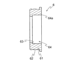
- the bearing case 6 has a substantially cylindrical main body 61 that accommodates the rolling bearing 2, and is fixed to the inner side of the housing D ⁇ b> 1 by a fixing portion 62 formed on the outer peripheral surface of the main body 61. (See FIG. 1). As shown in FIG. 3, the bearing case 6 has a stepped portion 63 that can be engaged with one end face of the outer ring 22. Further, the bearing case 6 is provided with an opening accommodating portion 64 for accommodating the rolling bearing 2 inside the main body 61 (see FIG. 3), and the main body on the side opposite to the side where the stepped portion 63 is formed.
- the outer ring 22 is clamped from both sides in the axis X direction by crimping the peripheral edge part 64a of the opening accommodating part 64 among the end surfaces of 61, and the movement in the axis X direction between the bearing case 6 and the outer ring 22 is restricted.
- the “base material” may be a member to which the rolling bearing 2 is attached via the first fixing member 4 and the second fixing member 5, and the inner ring 21 as in the present embodiment. Unlike the present embodiment, it may be provided inside, or may be provided outside the outer ring 22 of the rolling bearing 2.
- the base material 3 is configured to be rotatable inside the inner ring 21, but the base material inside the inner ring 21 is configured not to rotate, and a member provided outside the outer ring 22 is rotated. You may comprise.
- the base material on the outer side of the outer ring 22 may be rotatable, and a member provided on the inner side of the inner ring 21 may not be rotatable.
- the base member may be made non-rotatable and the member provided inside the inner ring 21 may be made rotatable.
- the shape of the base material 3 is not limited to the illustrated cylindrical shape, and any shape can be adopted as long as the inner ring 21 or the outer ring 22 can be attached.
- the base material 3 of this embodiment is shown as a power transmission member as described above, and as shown in FIGS. 2 and 4, the gear portion connected to the output side of the gear box D3 of the power portion D. 31, a shaft portion 32 that is rotatably supported inside the inner ring 21, and a sleeve screw connection portion 33 that is connected to the sleeve screw Ac ⁇ b> 1.
- the shaft portion 32 is formed with an engaging portion 32a. The engaging portion 32a will be described later.
- the gear portion 31 has gear teeth on the outer periphery that mesh with a gear (not shown) in the gear box D3.
- the gear part 31 and the shaft part 32 are formed on the same axis, and when the gear part 31 rotates, the shaft part 32 also rotates.
- a sleeve screw connection portion 33 is provided at the end of the shaft portion 32 on the actuator Ac side (right side in FIGS. 2 and 4), and the sleeve screw Ac 1 is connected to the sleeve screw connection portion 33.
- FIG. 1 In the present embodiment, as shown in FIG.
- the sleeve screw connection portion 33 includes a cylindrical barrel portion 33 a to which the sleeve screw Ac ⁇ b> 1 is fitted, and an end portion on the shaft portion 32 side of the barrel portion 33 a.
- the flange portion 33b protrudes outward from the outer periphery of the portion 33a.
- the sleeve screw Ac1 and the sleeve screw connecting portion 33 are connected.
- a fitting hole 33d into which the attachment shaft G2 (see FIG. 1) of the gas spring G is fitted is formed along the axis X at the end of the body portion 33a on the actuator Ac side.
- the power part D and the actuator Ac are connected by the bearing structure 1, and the power part D is driven as described above, and the bearing structure 1 transmits the power of the power part D to the actuator Ac.
- the linear motion device A expands and contracts.
- the rolling bearing 2 is attached to support the rotating shaft when the base material 3 as the power transmission member rotates.
- an engaging portion 32 a is formed on the base material 3 and engages with the engaged portion 52 a of the second fixing member 5.
- the engaging part 32a is formed in the axial part 32 of the base material 3, and the engaging part 32a is arrange
- the member 4 and the second fixing member 5 are disposed between the inner ring 21 and the shaft portion 32.
- the shape of the engaging portion 32 a is not particularly limited, in the present embodiment, the engaging portion 32 a is an annular groove formed on the outer periphery of the base material 3.
- the engaged portion 52a of the second fixing member 5 is engaged with the annular groove.
- the second fixing member 5 is difficult to come off between the rolling bearing 2 and the base material 3.
- the 1st fixing member 4 and the 2nd fixing member 5 may be arrange
- the engaging portion 32a is shown as an annular groove formed on the outer periphery of the substrate 3 (shaft portion 32), but the engaging portion 32a and the engaged portion 52a are engaged. And if it has the effect mentioned later, it does not necessarily need to be formed in an annular shape.
- the engaging portion 32a is formed in a concave shape, and the engaged portion 52a is configured to engage with the engaging portion 32a formed in a concave shape, but the engaging portion 32a is convex.
- the engaged portion 52a may be configured to engage with the convex engaging portion.
- the restriction of the movement of the rolling bearing 2 by the first restriction part 41 is not particularly limited as long as the first restriction part 41 restricts the movement of the rolling bearing 2, and the first restriction part 41 directly
- the movement of the rolling bearing 2 may be regulated or the movement may be regulated indirectly.
- the first fixing member 4 regulates the movement of the rolling bearing 2 in one direction in the axis X direction in the bearing structure 1.
- positioned between the base material 3 and the rolling bearing 2 has the 1st control part 41 which controls the movement to the one side of the axis X direction of the rolling bearing 2. Yes.
- the movement of the first fixing member 4 to one side is restricted when one end surface in the axis X direction of the first restricting portion 41 abuts on the flange portion 33b of the sleeve screw connecting portion 33.
- the movement to the other side of the 1st fixing member 4 is controlled by the 2nd fixing member 5 mentioned later.
- the first restricting portion 41 is configured to move the inner ring 21 of the rolling bearing 2 or the rolling bearing 2 even if the rolling bearing 2 tries to move to one side in the axis X direction, for example, the right side in FIG. It abuts on the outer ring 22 (in this embodiment, abuts on the inner ring 21).
- the first fixing member 4 is immovable in the axis X direction, the movement of the rolling bearing 2 to one side (right side in FIG. 2) in the axis X direction is restricted.
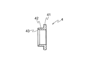
- the first fixing member 4 has an inner diameter that can be inserted outside the outer periphery of the shaft portion 32, and the shaft portion 32, the inner ring 21, and the like. And a cylindrical interposition part 42 interposed between them and an axial end of one of the interposition parts 42 in the axial direction (right side in FIG. 2) projecting radially outward from the outer periphery.
- a flange-shaped first restricting portion 41 capable of abutting on one end surface (right side in FIG. 2) of the direction is provided.
- the first restricting portion 41 may have a shape other than the flange shape as long as the movement of the rolling bearing 2 in one direction in the axis X direction can be restricted.
- the 1st fixing member 4 may be provided integrally with the site
- other members for example, sleeves
- the movement of the rolling bearing 2 in one direction of the axis X may be restricted by using the screw connection portion 33) as the first fixing member.
- the first fixing member 4 of the present invention is not limited to a member interposed between the base material 3 and the rolling bearing 2, for example, a base of the rolling bearing 2 such as a sleeve screw connection portion 33.
- the movement in one direction in the axis X direction (right direction in FIG. 2) is regulated directly or indirectly by a member that is separated from the connection position with respect to the material 3 and cannot move with respect to the base material 3. May be.
- the first restricting portion 41 is made immovable relative to the base material 3 as a flange-like protruding portion that protrudes in the vertical direction over the entire circumference around the axis with respect to the axis X direction of the rolling bearing 2.
- the first fixing member 4 is provided.
- the first fixing member 4 is provided with an interposition portion 42 in order to prevent rattling of the rolling bearing 2 in the direction perpendicular to the axis X of the rolling bearing 2. You may have.
- the interposition part 42 restricts the movement of the first fixing member 4 to the other side in the axis X direction, and the engaged part 52a of the second fixing member 5 is engaged with the engaging part 32a. It also has a function of restricting movement from the alignment position.
- the interposition part 42 has a cylindrical shape that covers the base material 3 over the entire circumference of the base material 3.
- the first fixing member 4 is provided with a first restricting portion 41 at an end portion of the interposed portion 42 on one side in the axis X direction, and has a substantially L-shaped longitudinal section.
- the second fixing member 5 is a member that restricts the movement of the rolling bearing 2 in the other direction of the axis X, and restricts the movement of the rolling bearing 2 in both directions of the axis X direction together with the first fixing member 4.
- the second fixing member 5 includes a second restricting portion 51 that restricts the movement of the rolling bearing 2 in the other direction of the axis X, and an engaged portion 52a that engages with the engaging portion 32a. And a support portion 52b that supports the rolling bearing 2 in the radial direction.
- the engaged portion 52 of the second fixing member 5 is engaged with the engaging portion 32 a of the base material 3, so that the second fixing member 5 is pivoted with respect to the base material 3.
- Movement to the other side in the X direction is restricted.
- the 2nd control part 51 of the 2nd fixing member 5 controls the movement to the other of the direction of the axis X of the rolling bearing 2 in the direction opposite to the direction which the 1st control part 41 of the 1st fixing member 4 controls.
- the movement of the rolling bearing 2 in both directions in the axis X direction together with the first restricting portion 41 of the first fixing member 4 is restricted.
- the rolling bearing 2 is sandwiched between the first fixing member 4 and the second fixing member 5 from both sides in the axis X direction, and the engaged portion 52 of the second fixing member 5 and the engaging portion 32a of the base member 3 are Since the second fixing member 5 is configured to engage and not move relative to the base material 3, the base material 3 and the rolling bearing 2 are interposed via the first fixing member 4 and the second fixing member 5. Thus, it is fixed so as not to be relatively movable in the axis X direction.
- the rolling bearing 2 has a structure sandwiched between the first restricting portion 41 and the second restricting portion 51 in the axis X direction, movement in the axis X direction is restricted.
- the restriction of the movement of the rolling bearing 2 by the second restriction part 51 is not particularly limited as long as the second restriction part 51 restricts the movement of the rolling bearing 2, and the second restriction part 51 directly
- the movement of the rolling bearing 2 may be regulated or the movement may be regulated indirectly.
- the second fixing member 5 that is immovable with respect to the base material 3 has a bowl-shaped second restricting portion 51 that protrudes in a direction perpendicular to the axis X direction of the rolling bearing 2, The surface of the inner ring 21 of the rolling bearing 2 on the other side in the axis X direction (left side in FIG. 2) and the second restricting portion 51 come into contact with each other so that the rolling bearing 2 is in the other direction in the axis X direction (left direction in FIG.
- the second fixing member 5 has a support portion 52 b that supports the rolling bearing 2 in the radial direction.
- the support portion 52b has a cylindrical shape, and is interposed between the rolling bearing 2 and the base 3 to support the rolling bearing 2 in the radial direction.
- the second restricting portion 51 may have a substantially L-shaped longitudinal section as a flange-like protruding portion that protrudes in the vertical direction over the entire circumference around the axis with respect to the axis X direction of the rolling bearing 2.
- the rectangular portion may have a shape extending radially outward from the axis X.
- the second restricting portion 51 is configured such that when the rolling bearing 2 is attached to the base material 3, the rolling bearing 2 is the other in the axis X direction, for example, the left side in FIG. 2. Even if it is going to move to the other, it contacts with the inner ring 21 or the outer ring 22 of the rolling bearing 2 (in this embodiment, contacts with the inner ring 21), thereby moving to the other side (left side in FIG. 2) of the rolling bearing 2 in the axis X direction. Prevent the movement of.
- the rolling bearing 2 is clamped by both the first restricting portion 41 of the first fixing member 4 and the second restricting portion 51 of the second fixing member 5, and the rolling bearing 2 moves to one and the other in the axis X direction. Is regulated.
- the second fixing member 5 has an inner diameter that can be inserted outside the outer periphery of the shaft portion 32, and the shaft portion 32, the inner ring 21, A cylindrical second interposed portion 52 interposed between the inner ring and the second intermediate portion 52 projecting radially outward from the outer periphery of the other axial end (left side in FIG.
- the 2nd intervention part 52 is comprised from the to-be-engaged part 52a and the support part 52b.
- the engaged portion 52a shown in FIG. 2 provided at the end of () engages with the engaging portion 32a of the substrate 3.
- the support portion 52b is 52 is a portion that supports the inner ring from the radial direction by contacting the inner ring 21.
- the end portion on the one side in the axis X direction of the second interposed portion 52 is used as the engaged portion 52a, and the engaged portion 52a is deformed and engaged with the engaging portion 32a. Even if the engaged portion 52a has a shape that can be engaged with the engaging portion 32a in advance (for example, an engaged portion formed by bending the second interposed portion 52 in the vertical direction). Good.
- the second restricting portion 51 is shown in a flange shape in advance, but after the tubular member having the engaged portion 52a is engaged with the engaging portion 32a of the base material 3.
- the rolling bearing 2 is inserted into the second fixing member 5 on which the flange-shaped second restricting portion 51 is not formed, and the second fixing member 5 is covered with the end of the inner ring 21 of the rolling bearing 2.
- the second fixing member 5 may be formed as the second restricting portion 51 by bending the end opposite to the engaging portion 52a to prevent the rolling bearing 2 from moving in the other direction in the axis X direction.
- the inner ring 21 is connected to the first restriction member 41 of the first fixing member 4 and the second restriction member 51 of the second fixing member 5.
- the first fixed member 4 and the second fixed member 5 are sandwiched from both sides in the direction, and the engaged portion 52a of the second fixing member 5 is engaged with the engaging portion 32a of the base material 3 (shaft portion 32).
- the movement in the axis X direction between the rolling bearing 2 and the base material 3 (shaft portion 32) can be restricted.
- the support part 52b of the second fixing member 5 is interposed between the rolling bearing 2 and the base material 3 (shaft part 32) and supports the rolling bearing 2 in the radial direction, the inner ring 21 of the rolling bearing 2 is supported.
- the first fixing member 4 and the second fixing member 5 are interposed between the inner ring 21 and the shaft portion 32 of the base material 3 provided inside the inner ring 21.
- the first fixing member shown in FIGS. 7A and 7B is shown between the outer ring 22 of the rolling bearing 2 and the base material having the engaging portion provided outside the outer ring 22. Even if the 40 and the second fixing member 50 are interposed, the same effect can be obtained.
- 7A and 7B the first restricting portion 41 and the second restricting portion 51 are arranged so that the first fixing member 40 and the second fixing member 50 for the outer ring 22 come into contact with the end surface of the outer ring 22. , Projecting inward from the intervening portion 42 and the second intervening portion 52.
- the first fixing member 40 and the second fixing member 50 that fix the outer ring 22 have basically the same functions as the first fixing member 4 and the second fixing member 5 that fix the inner ring 21, so Are denoted by the same reference numerals and will not be described in detail.
- the first fixing member 4 and / or the second fixing member 5 are press-fitted from both sides of the rolling bearing 2 in the axis X direction so that they are deformed and engaged on the annular groove. It is configured.
- one or both of the first fixing member 4 and the second fixing member 5 are made of a material capable of plastic deformation, and either one or both of the first fixing member 4 and the second fixing member 5 are used.
- the engaged portion 52a of the second fixing member 5 can be engaged with the engaging portion 32a of the base material 3 by press-fitting between the base material 3 and the rolling bearing 2 so as to approach in the axis X direction. .
- the press-fitting of the first fixing member 4 and the second fixing member 5 may be performed by directly pressing the first fixing member 4 and the second fixing member 5 or indirectly by another member such as a jig.
- the first fixing member 4 and the second fixing member 5 may be pressed and press-fitted.
- the engaged portion 52a is in contact with the first fixing member 4 and the axis X of the second fixing member 5 is contacted. Movement to one side of the direction can also be restricted.
- the engaged portion 52a engages the engaging portion 32a but also the inner peripheral surface of the inner ring 21 and the support portion by the deformation of the second interposed portion 52 of the second fixing member 5 52b can contact or the inner peripheral surface of the inner ring 21 can be pressed by the support portion 52b, so that the radial play of the rolling bearing 2 can be reliably eliminated.
- the engaged portion 52 a of the second fixing member 5 when the engaged portion 52 a of the second fixing member 5 is engaged with the annular groove, the engaged portion 52 a is the annular groove, so that the engaged portion 52 a is in the circumferential direction of the shaft portion 32. Therefore, the backlash between the rolling bearing 2 and the base material 3 can be eliminated uniformly, and the bonding strength between the rolling bearing 2 and the base material 3 can be increased.
- the first fixing member 4 and / or the second fixing member 5 are made deformable in this way, in order to facilitate deformation when the first fixing member 4 and / or the second fixing member 5 are press-fitted, FIG. 5 and FIG. 6, the first tapered surface 43 is formed at the distal end portion of the interposed portion 42 of the first fixing member 4, and the second tapered surface is formed at the distal end portion of the second interposed portion 52 of the second fixing member 5. 53 can also be formed.
- the first fixed member 4 and / or the second fixed member 5 are press-fitted from one or both sides in the axis X direction of the rolling bearing 2 so that the first tapered surface 43 and the second tapered surface 53 are pressed against each other.
- the engaged portion 52a engages with the engaging portion 32a. Therefore, when the first fixing member 4 and / or the second fixing member 5 is press-fitted into the gap between the rolling bearing 2 and the base material 3, the engaged portion 52a and the engaging portion 32a are easily engaged. Can be made.
- the rolling bearing 2 is put in the opening accommodating portion 64 of the bearing case 6 shown in FIG. 3, and the opening accommodating portion 64 of the bearing case 6 is in a state where the end surface of the outer ring 22 is in contact with the stepped portion 63 of the bearing case 6. And the outer ring 22 is sandwiched from both sides in the direction of the axis X. Further, as shown in FIG. 8 a, the first fixing member 4 is inserted into the shaft portion 32 of the base material 3 from the gear portion 31 side so that the first restricting portion 41 contacts the sleeve screw connecting portion 33.
- the integrated rolling bearing 2 and bearing case 6 are inserted from the gear portion 31 side of the base material 3, and the inner ring 21 is inserted into the first fixing member 4. It fits on the interposition part 42 (refer FIG. 8b).
- the outer diameter of the interposed portion 42 may be made smaller than the inner diameter of the inner ring 21 of the rolling bearing 2. .
- the interposition part 42 of the first fixing member 4 is shorter than the axial length of the inner ring 21 of the rolling bearing 2, and the tip of the interposition part 42 is substantially in the axis X direction of the inner ring 21.
- the engaging portion 32 a of the shaft portion 32 is also located at a substantially central portion of the inner ring 21 in the axis X direction.
- a first taper surface 43 and a second taper surface 53 are formed at the distal end of the interposed part 42 of the first fixing member 4 and the distal end of the second interposed part 52 of the second fixing member 5, respectively. ing.
- the first fixing member 4 first Due to the tapered surface 43, the engaged portion 52 a at the tip of the second interposed portion 52 of the second fixing member 5 is deformed toward the inside of the engaging portion 32 a of the shaft portion 32. If the second fixing member 5 continues to be press-fitted as it is, if the second fixing member 5 is formed of a material that is easily plastically deformed, such as aluminum, the engaged portion 52a is plasticized until it engages with the engaging portion 32a. It is deformed and enters the state shown in FIG.
- the sum of the volume of the portion inserted into the inner ring 21 of the first fixing member 4 and the volume of the portion inserted into the inner ring 21 of the second fixing member 5 is the inner side of the inner ring 21 and the shaft portion 32. 2 is included in the state shown in FIG. 2 due to the press-fitting of the second fixing member 5, when the volume of the gap between the engagement portion 32a and the engagement portion 32a is larger. And the inner peripheral surface of the inner ring 21 of the rolling bearing 2 and the support portion 52b of the second fixing member 5 are in contact with each other without a gap, and the shaft portion 32 of the base material 3 is held without any play. be able to.
- the 1st taper surface 43 of the 1st fixing member 4 is the inside of the inner ring
- the rolling bearing 2 when used in a linear motion device A provided in an elongated space such as a power lift gate, or when used for a small actuator or an actuator having a small arrangement space, the interior of the elongated space or narrow space Therefore, another member may be provided around the rolling bearing 2.
- another member may be provided around the rolling bearing 2.
- the rolling bearing 2 can be attached to the base member 3 with a simple structure, it does not interfere with other members around the rolling bearing 2.
Landscapes
- Engineering & Computer Science (AREA)
- General Engineering & Computer Science (AREA)
- Mechanical Engineering (AREA)
- Mounting Of Bearings Or Others (AREA)
- Support Of The Bearing (AREA)
- Rolling Contact Bearings (AREA)
Abstract
本発明の軸受構造1は、転がり軸受2と、転がり軸受2が取り付けられ、係合部32aを有する基材3と、転がり軸受2の軸X方向の一方への移動を規制する第一規制部41を有し、基材3に対して軸X方向に移動不能にされた第一固定部材4と、転がり軸受2の軸X方向の他方への移動を規制する第二規制部51と、係合部32aと係合する被係合部52aと、転がり軸受2を径方向に支持する支持部52bとを有する第二固定部材5とを備えることを特徴としているので、転がり軸受2の軸方向両側への移動を規制するとともに、転がり軸受2の径方向のガタを無くすことができる。
Description
本発明は、軸受構造に関する。
転がり軸受と軸を連結する構造として、特許文献1に記載された構造が開示されている。この特許文献1に開示された構造は、図9に示されるように、ピニオン軸100に止め筒101が係合される周溝102が設けられ、止め筒101が係合部と係合されることによって転がり軸受103を軸方向両側から挟みこむものである。
この構造は、ピニオン軸100に一側から止め筒101が外嵌され、止め筒101の一端を塑性変形させ、その後、止め筒101に転がり軸受103を挿入して、止め筒101の他端を塑性変形させて、図9に示されるように、転がり軸受103を軸方向から挟み込んでいる。
しかしながら、この特許文献1に示された構造では、転がり軸受103の軸方向の固定はできるが、ピニオン軸100、止め筒101、転がり軸受103など、用いられる部材の寸法公差などにより、互いの部材の間で転がり軸受103の径方向のガタが発生してしまうという問題がある。
そこで、本発明は、かかる問題に鑑みて、転がり軸受の軸方向両側への移動を規制するとともに、転がり軸受の径方向のガタを無くす軸受構造の提供を目的とする。
本発明の軸受構造は、転がり軸受と、前記転がり軸受が取り付けられ、係合部を有する基材と、前記転がり軸受の軸方向の一方への移動を規制する第一規制部を有し、前記基材に対して軸方向に移動不能にされた第一固定部材と、前記転がり軸受の軸方向の他方への移動を規制する第二規制部と、前記係合部と係合する被係合部と、前記転がり軸受を径方向に支持する支持部とを有する第二固定部材とを備えることを特徴とする。
また、前記係合部は、前記転がり軸受の内輪の内側に配置され、前記第一固定部材及び前記第二固定部材は、前記内輪と前記係合部との間に配置されることが好ましい。
また、前記係合部が前記基材の外周に形成された環状の溝であり、前記被係合部は、前記溝に係合されることが好ましい。
また、前記第一固定部材および/または前記第二固定部材が、前記転がり軸受の軸方向両側から圧入されることにより、前記環状の溝内で変形して係合されることが好ましい。
本発明によれば、転がり軸受の軸方向両側への移動を規制するとともに、転がり軸受の径方向のガタを無くすことができる。
以下、添付図面を参照し、本発明の軸受構造を詳細に説明する。
図1は、本発明の軸受構造1が、車両のバックドアのパワーリフトゲートなど、ヒンジを中心に回転することで開閉するドアの駆動装置に用いられる直動装置Aに適用された例を示している。なお、本発明の軸受構造1は、本実施形態で説明する直動装置Aに適用されるものに限定されるものではなく、本発明の目的の範囲内で、転がり軸受を有する様々な構造に適用が可能である。
図1に示されるように、直動装置Aは、動力部Dと、スリーブスクリューAc1およびナット部材Ac2を含むアクチュエータAcと、ガススプリングGと、車両のバックドア等の対象物に取り付けられる取付部材Mとを備え、動力部DとアクチュエータAcとは軸受構造1により連結されている。直動装置Aは、動力部Dからの動力により、アクチュエータAcが駆動され、直線方向に伸縮する。
動力部Dは、図1では特に詳細には示していないが、ハウジングD1と、ハウジングD1の内部に固定されたモータD2と、モータD2の出力軸に取り付けられたギヤボックスD3と、ハウジングD1の一端側(軸受構造1が連結される側とは反対側)に配置された回動支持部D4とを備えている。
ハウジングD1は、円筒形状の部材であり、動力部Dの外装であり、本実施形態では、直動装置Aの外装でもある。ハウジングD1は、内部に配置されたモータD2、ギヤボックスD3、動力部Dに連結された軸受構造1を保護している。また、ハウジングD1は、直動装置Aが動作するときの軸方向の荷重を支える構造部材としても作用しているため、強度を得ることができる筒体(例えば、鉄、アルミニウム合金等の金属製や、高強度のエンジニアリングプラスチック)で構成されている。
モータD2は、ハウジングD1の内部に、後述のアクチュエータAcと同軸となるように配置され、本実施形態においては、ハウジングD1と同軸となるように、すなわち、モータD2の出力軸(図示せず)がハウジングD1の中心軸周りに回転するように配置されている。なお、モータD2は直流モータ、交流モータ等電動モータを広く採用することが可能である。なお、モータD2は、直動装置Aの設置場所、動作対象物の大きさや重量などの動作条件によって決定可能である。例えば、自動車の扉を開閉するときに直動装置Aを用いる場合、自動車は直流電源を備えていることから、直流モータが好ましい。
モータD2は出力軸からの出力ロスを低減するため、ハウジングD1に対して回転しないようにかつ軸方向に移動しないように保持(固定)されている。なお、モータD2は移動しないようハウジングD1に強固に固定していてもよいし、キー、スプライン等を利用して軸周りの回転を抑えるとともに、ハウジングD1の内部に段差等を形成し軸方向の移動を規制するようにしてもよい。ハウジングD1へのモータD2の取り付けは、モータD2のハウジングD1に対する軸周りの回転と軸方向の移動を抑制する方法を広く採用することが可能である。
ギヤボックスD3もモータD2と同様、ハウジングD1に保持されている。ギヤボックスD3は内部に複数枚の歯車を備えており、一方の端部が入力側(図1中、左側)、他方の端部が出力側(図1中、右側)となっている。そして、ギヤボックスD3の入力側には、モータD2の出力軸が接続されており、出力側には後述する軸受構造1のギヤ部31(図2参照)が接続されている。図1に示しているように、ギヤボックスD3は、モータD2の出力軸とギヤ部31とを、両方の軸の軸心が一致するように接続している。そして、ギヤボックスD3は入力側から入力された回転の速度を落とす(減速する)とともに、回転力(トルク)を増加(増幅)させて出力側から出力する。
直動装置Aにおいて、ギヤボックスD3はモータD2の出力軸の出力(回転)をギヤ部31に伝達するとき、回転速度を落とし、トルクを増加させて伝達している。また、ギヤボックスD3を備えていることにより、直動装置AのモータD2として、発生トルクが小さいモータ(一般に小型モータ)を採用可能となっている。なお、モータD2が低速回転で十分なトルクを発生できるものである場合、ギヤボックスD3を省略し、出力軸とギヤ部31を直接接続する、或いは、出力軸でギヤ部31を兼用する構成としてもよい。また、ギヤボックスD3は、ギヤ部31から入力される軸方向の力が、モータD2に作用するのを抑制する緩衝部材としての効果も備えている。
そして、ハウジングD1の端部に回動支持部D4が取り付けられている。回動支持部D4は、取り付け対象物に対して、直動装置Aが回転可能に支持することができるように構成され、本実施形態では、ハウジングD1の軸方向に突出した板状の部材であり、中央部分に貫通孔が形成されている。この貫通孔にピン又はねじを通し、動力部D、すなわち、直動装置A全体が、貫通孔を中心として、回動可能となるように支持物体(例えば、自動車の車体等)に取り付けられる。なお、回動支持部D4として、ボールソケットジョイント、クレビス、ピンジョイント等のような構成を広く採用することが可能である。
アクチュエータAcは、ハウジングD1の内部に、ハウジングD1に対して摺動可能に収容されたガイドケースAc3、ガイドケースAc3と接触しないように配置されたスリーブスクリューAc1と、スリーブスクリューAc1の外周に形成された螺旋溝Ac11の溝上を移動するナット部材Ac2と、ガイドケースAc3の内部に配置され、ナット部材Ac2に接続する円筒形状の連動部材Ac4とを有している。
スリーブスクリューAc1は、円筒形状の部材であり、円筒の外周部分に形成された螺旋溝(雄ねじ)Ac11を有している。スリーブスクリューAc1には、動力部Dからの回転力を、軸受構造1を介してスリーブスクリューAc1に伝達するために、軸受構造1に連結される連結部Ac12と、円筒形状の内部に形成され、ガススプリングG(ガスシリンダG1)が取り付けられるガススプリング取付部Ac13とが設けられている。なお、スリーブスクリューAc1は、ガススプリングGの外周に直接設けられても良い。
螺旋溝Ac11は、ここでは雄ねじである。螺旋溝Ac11は、ナット部材Ac2の螺旋溝Ac21に螺合している。そして、連結部Ac12は、後述する基材3のスリーブスクリュー接続部33(図2参照)の回転に応じて回転可能にスリーブスクリュー接続部33と連結されて、モータD2の回転力がスリーブスクリューAc1に伝達される。なお、連結部Ac12とスリーブスクリュー接続部33とは、ネジなどの公知の固着手段により連結しても良いし、スプラインや連結部Ac12に円以外の形状の凹穴を形成しておき、スリーブスクリュー接続部33の先端を凹穴と同じ形状に形成して挿入する構成のもの、キー及びキー溝を利用するもの等、スリーブスクリュー接続部33の回転をスリーブスクリューAc1に確実に伝達できる形状のものを広く採用することが可能である。連結部Ac12には、基材3の軸方向の力を受けるための補強板が備えられる場合もある。このように、連結部Ac12とスリーブスクリュー接続部33とが連結されていることで、基材3の回転が、連結部Ac12に伝達され、スリーブスクリューAc1が回転する。動きの詳細については、後述する。
ガススプリング取付部Ac13の内部には、少なくともガススプリングGのガスシリンダG1が取り付けられる。ガススプリング取付部Ac13は、ガスシリンダG1がスリーブスクリューAc1と同軸となるように、ガスシリンダG1を支持している。このとき、ガススプリング取付部Ac13は、ガスシリンダG1をスリーブスクリューAc1に対して動かないようにしっかり保持していてもよいし、回転可能に支持していてもよい。ガススプリング取付部Ac13によるガスシリンダG1の支持は、ガスシリンダG1内のピストンロッドの摺動方向が、スリーブスクリューAc1の軸方向と同じであればよく、ピストンロッドの軸とスリーブスクリューAc1の軸とが重なっていればさらに好ましい。
ナット部材Ac2は、内側に雌ねじ状の螺旋溝Ac21を備えた部材である。この雌ねじ状の螺旋溝Ac21が、スリーブスクリューAc1の雄ねじ状の螺旋溝Ac11と螺合している。なお、直動装置Aでは、スリーブスクリューAc1とナット部材Ac2とは、それぞれ、雄ねじ、雌ねじを備えた構成となっているが、これに限定されるものではなく、例えば、ボールねじ構造のように、スリーブスクリューAc1の回転をスリーブスクリューAc1に外嵌しているナット部材Ac2を軸方向に移動させる力に変換できる構成のものを広く採用することが可能である。ナット部材Ac2はスリーブスクリューAc1の螺旋溝Ac11が形成されている範囲で移動する。
連動部材Ac4は、円筒形状の部材であり、ガイドケースAc3内部に取り付けられている。図示は省略しているが、連動部材Ac4は、スリーブスクリューAc1に対して回転しないようにする回転防止部材が備えられている。そして、連動部材Ac4の一方の端部には、連動部材Ac4とナット部材Ac2とが相対的に動かないように、ナット部材Ac2が接続されている。本実施形態においては、ナット部材Ac2は連動部材Ac4の端部(動力部D側の端部)に接続されている。
連動部材Ac4はスリーブスクリューAc1に対する回転が規制されていることから、連動部材Ac4に固定されたナット部材Ac2もスリーブスクリューAc1に対する回転が規制される。この状態で、動力部Dからの動力によってスリーブスクリューAc1が回転すると、スリーブスクリューAc1がナット部材Ac2に対して回転する。これにより、螺旋溝Ac11と螺旋溝Ac21との作用により、ナット部材Ac2及びナット部材Ac2が固定された連動部材Ac4がスリーブスクリューAc1の軸方向に沿って移動する。
ガススプリングGは、内部に封入されたガスの圧力で、外部に付勢力を与える部材である。ガスシリンダG1と、ガスシリンダG1の内部に摺動可能に配置されたピストンヘッド(図示せず)と、一端がピストンヘッドに取り付けられ他端がガスシリンダG1より突出しているピストンロッドとを備えている。ガススプリングGの構成は、従来よく知られているものであり、詳細は省略する。
ガスシリンダG1は内部にガスが封入されており、一端が閉じられているとともに、他端にピストンロッドが貫通する孔を有する円筒形状の部材である。ガスシリンダG1は内部のガスの圧力でピストンヘッドを押し(引き)、ピストンロッドに軸方向の力が作用する。ピストンロッドのガスシリンダG1から突出した先端は取付部材Mに、回転可能に接続されている。
なお、直動装置Aでは、直動装置Aが最も伸びた状態(すなわち、ナット部材Ac2がスリーブスクリューAc1の先端(図1中、右側の端部)に到達した状態)でも、ガススプリングGは、ガスシリンダG1及びピストンロッドが外側に向かって付勢力を加える(反発力を発生する)構造を有している。なお、本実施形態では、ガススプリングGを用いたガススプリング式のアクチュエータAcが示されているが、ガススプリング式のアクチュエータAcに代えてスプリング式のアクチュエータ(図示せず)を用いても構わない。スプリング式のアクチュエータの場合は、ハウジングD1の中央に配置されているガスシリンダG1に代えて、図1におけるアクチュエータAc部分のハウジングD1の内周に沿ってスプリングを配置し、スプリングの付勢力により、アクチュエータの動きをアシストすることができる。
取付部材Mは、直動装置Aで動作させる動作対象物(例えば、車両の場合、リヤドア等)に取り付けられる部材である。取付部材Mは、連動部材Ac4の先端に嵌合する嵌合部M1と、上述の動作対象物に取り付けられる取付部M2と、ピストンロッドの先端を回転可能に支持するベアリングM3とを備えている。
嵌合部M1は、連動部材Ac4の先端に嵌め込まれ、固定された部材である。これにより、取付部材Mは連動部材Ac4に同期して動作する。直動装置Aにおいて、嵌合部M1は連動部材Ac4に圧入により固定されているが、これに限定されるものではなく、連動部材Ac4と嵌合部M1とをしっかり固定できる方法を広く採用することができる。
取付部M2は、係合孔を備えており、この係合孔にねじ、ピン、リベット等の緊結具を挿通し、緊結具を上述の動作対象物に回動可能に取り付けられる。このように取り付けられることで、取付部材Mは、動作対象物に緊結具を中心として回動可能に取り付けられる。
つぎに、本発明の軸受構造1について説明する。図2は、図1に示した直動装置Aから、軸受構造1以外の部分を取り除いた、軸受構造1の部分断面図である。本発明の軸受構造1は、図2に示されるように、転がり軸受2と、転がり軸受2が取り付けられ、係合部32aを有する基材3と、転がり軸受2の軸X方向の一方への移動を規制する第一規制部41を有し、基材3に対して軸X方向に移動不能にされた第一固定部材4と、転がり軸受2の軸X方向の他方への移動を規制する第二規制部51と、係合部32aと係合する被係合部52aと、転がり軸受2を径方向に支持する支持部52bとを有する第二固定部材5とを備えている。
本実施形態では、転がり軸受2は、転がり軸受2の内輪21と外輪22(以下、それぞれ単に内輪21、外輪22という)とを有するラジアルベアリングとして示されている。転がり軸受2は、公知の転がり軸受を用いることができ、特に図示した転がり軸受に限定されるものではない。
本実施形態では、基材3は、内輪21の内側に、第一固定部材4および第二固定部材5を介して転がり軸受2に間接的に取り付けられる、動力部Dからの動力をアクチュエータAcに伝達する動力伝達部材として示されている。また、本実施形態では、外輪22の外側には、第一固定部材4および第二固定部材5は設けられておらず、軸受ケース6により外輪22が保持されている。
軸受ケース6は、図2および図3に示されるように、転がり軸受2を収容する略円筒状の本体61を有し、本体61の外周面に形成された固定部62により、ハウジングD1の内側に固定されている(図1参照)。軸受ケース6は、図3に示されるように、外輪22の一方の端面と係合可能な段部63を有している。また、軸受ケース6は、本体61の内側には、転がり軸受2を収容するための開口収容部64が設けられ(図3参照)、段部63が形成されている側とは反対側の本体61の端面のうち、開口収容部64の周縁部64aをかしめることにより、外輪22を軸X方向で両側から挟み込んで、軸受ケース6と外輪22との間での軸X方向の移動を規制している(図2参照)。なお、本明細書において、「基材」とは、第一固定部材4および第二固定部材5を介して転がり軸受2が取り付けられる部材であればよく、本実施形態のように、内輪21の内側に設けられてもよいし、本実施形態とは異なり、転がり軸受2の外輪22の外側に設けられてもよい。また、基材3は本実施形態では、内輪21の内側において回転可能に構成されているが、内輪21の内側の基材を回転しないように構成し、外輪22の外側に設けられる部材を回転可能に構成してもよい。同様に外輪22の外側に基材が設けられた場合には、外輪22の外側の基材を回転可能にし、内輪21の内側に設けられる部材を回転不能にしてもよいし、外輪22の外側の基材を回転不能にし、内輪21の内側に設けられる部材を回転可能にしてもよい。また、基材3の形状は、図示した円筒形状に限定されるものではなく、内輪21または外輪22を取り付けることができるものであれば、任意の形状を採用することができる。
本実施形態の基材3は、上述したように、動力伝達部材として示されており、図2および図4に示されるように、動力部DのギヤボックスD3の出力側に接続されるギヤ部31と、内輪21の内側で回転可能に支持される軸部32と、スリーブスクリューAc1に接続されるスリーブスクリュー接続部33とを備えている。図2および図4に示されるように、軸部32には係合部32aが形成されているが、係合部32aについては後述する。
ギヤ部31は、図2および図4に示されるように、ギヤボックスD3内のギヤ(図示せず)と噛み合うギヤ歯を外周に有している。ギヤ部31と軸部32とは同軸上に形成され、ギヤ部31が回転すると軸部32も回転する。軸部32のアクチュエータAc側(図2および図4中、右側)の端部には、スリーブスクリュー接続部33が設けられており、スリーブスクリュー接続部33にスリーブスクリューAc1が接続される。本実施形態では、スリーブスクリュー接続部33は、図4に示されるように、スリーブスクリューAc1が外嵌される円柱状の胴部33aと、胴部33aの軸部32側の端部において、胴部33aの外周から外側に向かって突出したフランジ部33bを有している。スリーブスクリューAc1は、胴部33aに外嵌されたとき、フランジ部33bと当接して停止し、胴部33aの外周から中心部に向かって形成された固定孔33cに、ネジなどの公知の固定手段(図示せず)が固定されることにより、スリーブスクリューAc1とスリーブスクリュー接続部33とが接続される。また、胴部33aのアクチュエータAc側の端部には、ガススプリングGの取付軸G2(図1参照)が嵌合される嵌合孔33dが軸Xに沿って形成されている。このようにして、動力部DとアクチュエータAcとが、軸受構造1により連結されて、上述したように、動力部Dが駆動され、軸受構造1が動力部Dの動力をアクチュエータAcに伝達することにより、直動装置Aが伸縮する。
この動力伝達部材としての基材3が回転するときの回転軸を支持するために、転がり軸受2が取り付けられる。この転がり軸受2を基材3に取り付けるために、基材3には係合部32aが形成され、第二固定部材5の被係合部52aと係合する。本実施形態では、基材3の軸部32に係合部32aが形成され、図2に示されるように、係合部32aは、転がり軸受2の内輪21の内側に配置され、第一固定部材4及び第二固定部材5は、内輪21と軸部32との間に配置されている。係合部32aの形状は特に限定されるものではないが、本実施形態では、係合部32aは基材3の外周に形成された環状の溝である。第二固定部材5の被係合部52aが、前記環状の溝に係合される。被係合部52aが前記環状の溝に係合されることにより、第二固定部材5が転がり軸受2と基材3との間から抜けにくくなる。なお、第一固定部材4および第二固定部材5は、外輪22の外側に配置されてもよく、その場合、第一固定部材4および第二固定部材5は、外輪22の外側に設けられた基材(たとえば、軸受ケースや転がり軸受2を収容するハウジングなど)の係合部との間に配置される。また、係合部32aは本実施形態では、基材3(軸部32)の外周に形成された環状の溝として示されているが、係合部32aと被係合部52aとが係合して、後述する効果を奏するものであれば、必ずしも環状に形成されている必要はない。また、本実施形態では、係合部32aが凹状に形成され、被係合部52aが凹状に形成された係合部32aに係合するように構成されているが、係合部32aを凸状に形成し、被係合部52aを凸状の係合部に係合するように構成してもよい。第一規制部41による転がり軸受2の移動の規制については、第一規制部41が転がり軸受2の移動を規制するものであれば、特に限定されるものではなく、第一規制部41が直接転がり軸受2の移動を規制してもよく、間接的に移動を規制してもよい。
第一固定部材4は、軸受構造1において、転がり軸受2の軸X方向の一方への移動を規制する。本実施形態では、基材3と転がり軸受2との間に配置される第一固定部材4は、転がり軸受2の軸X方向の一方への移動を規制する第一規制部41を有している。本実施形態においては、第一規制部41の軸X方向における一方の端面がスリーブスクリュー接続部33のフランジ部33bと当接することにより、第一固定部材4の一方への移動が規制される。また、後述する第二固定部材5により、第一固定部材4の他方への移動が規制される。第一規制部41は、転がり軸受2が基材3に取り付けられたときに、転がり軸受2が軸X方向の一方、たとえば図2中、右側に移動しようとしても、転がり軸受2の内輪21または外輪22と当接(本実施形態では内輪21と当接)する。この際、第一固定部材4は、軸X方向に移動不能とされているため、転がり軸受2の軸X方向の一方(図2中、右側)への移動を規制する。本実施形態では、第一固定部材4は、図2および図5に示されるように、軸部32の外周の外側に挿着することが可能な内径を有し、軸部32と内輪21との間に介装される円筒状の介装部42と、介装部42の軸方向の一方(図2中、右側)の端部外周から径方向外側に向かって突出し、内輪21の軸X方向の一方(図2中、右側)の端面と当接可能なフランジ状の第一規制部41とを備えている。なお、第一規制部41は、転がり軸受2の軸X方向の一方への移動を規制することができれば、フランジ状以外の他の形状であってもよい。また、第一固定部材4は、第一規制部41、介装部42以外の他の機能を有する部位、たとえばスリーブスクリュー接続部33等と一体的に設けられたものであってもよい。また、第一固定部材4は、転がり軸受2の軸X方向の一方向への移動を規制する第一規制部41を有していれば、必ずしも基材3の軸部32と内輪21との間に介装する必要はなく、たとえば、図5に示す本実施形態の第一固定部材4を設けずに、転がり軸受2の内輪21または外輪22の端面と当接する他の部材(たとえば、スリーブスクリュー接続部33)を第一固定部材として、転がり軸受2の軸X方向の一方向への移動を規制してもよい。なお、本発明の第一固定部材4については、基材3と転がり軸受2との間に介在する部材に限定されるものではなく、例えばスリーブスクリュー接続部33のように、転がり軸受2の基材3に対する接続位置より離間して、基材3に対して移動不能とされた部材によって、軸X方向の一方(図2右方向)への移動が直接または間接的に規制されるようにされてもよい。本実施形態においては、第一規制部41は、転がり軸受2の軸X方向に対して軸周り全周にわたって垂直方向に突出したフランジ状の突部として、基材3に対して移動不能にされた第一固定部材4に設けられている。第一固定部材4は、転がり軸受2の移動を規制する第一規制部41以外に、転がり軸受2の軸Xに対して垂直方向における転がり軸受2のガタを防止するために、介装部42を有してもよい。本実施形態においては、介装部42は、第一固定部材4の軸X方向の他方側への移動の規制、並びに、第二固定部材5の被係合部52aが係合部32aに対する係合位置から移動することを規制する機能も有している。介装部42は、基材3の全周にわたって基材3を覆う筒状である。第一固定部材4は、軸X方向の一方における介装部42の端部に第一規制部41が設けられ、縦断面が略L字状の形状を有している。
第二固定部材5は、転がり軸受2の軸X方向の他方への移動を規制する部材であり、第一固定部材4とともに転がり軸受2の軸X方向の両方向への移動を規制する。第二固定部材5は、図2に示されるように、転がり軸受2の軸X方向の他方への移動を規制する第二規制部51と、係合部32aと係合する被係合部52aと、転がり軸受2を径方向に支持する支持部52bとを有している。本発明の第二固定部材5は、第二固定部材5の被係合部52が基材3の係合部32aと係合することにより、第二固定部材5が基材3に対して軸X方向の他方への移動が規制される。そして、第二固定部材5の第二規制部51が、第一固定部材4の第一規制部41が規制する方向とは反対方向の、転がり軸受2の軸X方向の他方への移動を規制して、第一固定部材4の第一規制部41とともに転がり軸受2の軸X方向の両方向への移動が規制される。したがって、第一固定部材4と第二固定部材5とで転がり軸受2を軸X方向の両側から挟み込み、さらに第二固定部材5の被係合部52と基材3の係合部32aとが係合して、第二固定部材5が基材3に対して移動しないように構成されているため、基材3と転がり軸受2とが、第一固定部材4と第二固定部材5を介して軸X方向で相対移動不能に固定される。ここで、転がり軸受2は、軸X方向に対し第一規制部41と第二規制部51とで狭持された構造となるため、軸X方向の移動が規制される。第二規制部51による転がり軸受2の移動の規制については、第二規制部51が転がり軸受2の移動を規制するものであれば、特に限定されるものではなく、第二規制部51が直接転がり軸受2の移動を規制してもよく、間接的に移動を規制してもよい。本実施形態においては、基材3に対して移動不能にされた第二固定部材5が転がり軸受2の軸X方向に対して垂直方向に突出した鍔状の第二規制部51を有し、転がり軸受2の内輪21における軸X方向の他方側(図2左側)の面と第二規制部51とが当接することにより、転がり軸受2が軸X方向の他方(図2左方向)に対して移動不能とされている。第二固定部材5は、転がり軸受2の径方向に支持する支持部52bを有する。本実施形態において、支持部52bは、円筒状であり、転がり軸受2と基体3との間に介在して、転がり軸受2を径方向に支持する。第二規制部51は、転がり軸受2の軸X方向に対して軸周り全周にわたって垂直方向に突出したフランジ状の突部として、縦断面が略L字状の形状を有していてもよく、矩形部が軸Xより外側に向けて放射状に延びた形状であってもよい。
図2を参照して、より詳細に説明すると、第二規制部51は、転がり軸受2が基材3に取り付けられたときに、転がり軸受2が軸X方向の他方、たとえば図2中、左側に移動しようとしても、転がり軸受2の内輪21または外輪22と当接(本実施形態では内輪21と当接)することにより、転がり軸受2の軸X方向の他方(図2中、左側)への移動を防止する。具体的には、第一固定部材4の第一規制部41と第二固定部材5の第二規制部51との両方により挟持されて、転がり軸受2は軸X方向の一方および他方へ移動することが規制される。本実施形態では、第二固定部材5は、図2および図6に示されるように、軸部32の外周の外側に挿着することが可能な内径を有し、軸部32と内輪21との間に介装される円筒状の第二介装部52と、第二介装部52の軸方向の他方(図2中、左側)の端部外周から径方向外側に向かって突出し、内輪21の軸X方向の他方(図2中、左側)の端面と当接可能なフランジ状の第二規制部51とを備えている。第二介装部52は、被係合部52aと支持部52bとから構成されている。詳細は後述するが、本実施形態では、第2介装部52が係合部32aと内輪21との間に配置されたとき、支持部52bの軸X方向の一方側(図2中、右側)の端部に設けられた、図2に示す被係合部52aが、基材3の係合部32aと係合する。支持部52bは、第二固定部材5が軸部32と内輪21との間の隙間に挿着され、被係合部52aが係合部32aと係合されたときに、第二介装部52のうち内輪21と接触することにより、内輪を径方向から支持する部分である。なお、本実施形態では、第二介装部52の軸X方向の一方側の端部を被係合部52aとして、被係合部52aが変形して係合部32aに係合するものでもよく、被係合部52aを予め係合部32aに係合できる形状(たとえば、第二介装部52に対して垂直方向に曲げて形成された被係合部)としたものであってもよい。また、本実施形態では、第二規制部51を予めフランジ状としたものを示しているが、被係合部52aを有する筒状部材を基材3の係合部32aに係合させた後に、転がり軸受2をフランジ状の第二規制部51が形成されていない第二固定部材5上に挿通し、転がり軸受2の内輪21の端面に当接するように第二固定部材5のうち、被係合部52aと反対側の端部を折り曲げて第二規制部51として第二固定部材5を形成し、転がり軸受2の軸X方向の他方への移動を防止してもよい。
ここで、本実施形態の軸受構造1は、図2に示されるように、内輪21を第一固定部材4の第一規制部41と第二固定部材5の第二規制部51とで軸X方向の両側から挟み込み、第二固定部材5の被係合部52aが、基材3(軸部32)の係合部32aと係合することにより、第一固定部材4、第二固定部材5、転がり軸受2および基材3(軸部32)の間での軸X方向の移動を規制することができる。さらに、第二固定部材5の支持部52bが、転がり軸受2と基材3(軸部32)の間に介装されて、転がり軸受2を径方向に支持するため、転がり軸受2の内輪21と基材3(軸部32)との間の径方向のガタを無くすことができる。したがって、本発明では、第二固定部材5の被係合部52aと基材3の係合部32aとが係合することにより、転がり軸受2の軸X方向両側への移動を規制するとともに、転がり軸受2の径方向のガタを無くすことができる。
なお、図2に示した実施形態では、内輪21と内輪21の内側に設けられた基材3の軸部32との間に、第一固定部材4および第二固定部材5が介装されたものを示したが、転がり軸受2の外輪22と、外輪22の外側に設けられた係合部を有する基材との間に、図7(a)および(b)に示す、第一固定部材40および第二固定部材50を介装させたものであっても、同様の効果を得ることができる。図7(a)および(b)に示す外輪22用の第一固定部材40および第二固定部材50は、外輪22の端面と当接するように、第一規制部41および第二規制部51が、介装部42および第二介装部52から内側に突出している。なお、外輪22を固定する第一固定部材40および第二固定部材50は、内輪21を固定する第一固定部材4および第二固定部材5と基本的に機能が同じであるため、各部位には同じ参照符号を用い、詳細な説明は省略する。
また、本実施形態では、第一固定部材4および/または第二固定部材5が、転がり軸受2の軸X方向両側から圧入されることにより、環状の溝上で変形して係合されるように構成されている。この場合、第一固定部材4、第二固定部材5のいずれか一方または両方が、塑性変形が可能な材料で構成され、第一固定部材4、第二固定部材5のいずれか一方または両方を軸X方向で近付くように基材3と転がり軸受2との間に圧入して、第二固定部材5の被係合部52aを、基材3の係合部32aと係合させることができる。ここで、第一固定部材4および第二固定部材5の圧入は、第一固定部材4および第二固定部材5をそれぞれ直接押圧して圧入してもよいし、治具等の別部材によって間接的に第一固定部材4および第二固定部材5を押圧して圧入してもよい。第一固定部材4および/または第二固定部材5を転がり軸受2の軸X方向の一方または両側から圧入することにより、環状の溝内で被係合部52aが変形して、被係合部52aと係合部32aとが係合する。この変形において、第一固定部材4と、第二固定部材5とが当接した状態となるので、被係合部52aが第一固定部材4と当接して、第二固定部材5の軸X方向の一方側への移動を規制することもできる。その係合の際に、第二固定部材5の第二介装部52は、被係合部52aが係合部32aと係合するだけでなく、変形により内輪21の内周面と支持部52bとが接触または内輪21の内周面を支持部52bが押圧して、転がり軸受2の径方向のガタを確実に無くすことができる。また、第二固定部材5の被係合部52aが、環状の溝に係合される場合、係合部32aが環状の溝であることにより、被係合部52aが軸部32の周方向でほぼ均一に係合するため、転がり軸受2と基材3との間のガタについても均一に無くすことができ、転がり軸受2と基材3との接合強度を高めることができる。
このように第一固定部材4および/または第二固定部材5を変形可能とした場合、第一固定部材4および/または第二固定部材5の圧入時に変形しやすくするために、図5および図6に示されるように、第一固定部材4の介装部42の先端部に第一テーパ面43を形成し、第二固定部材5の第二介装部52の先端部に第二テーパ面53を形成することもできる。これにより、第一固定部材4および/または第二固定部材5が転がり軸受2の軸X方向の一方または両側から圧入されることにより、第一テーパ面43と第二テーパ面53とが互いに押圧されて、被係合部52aが係合部32aに係合する。したがって、第一固定部材4および/または第二固定部材5を転がり軸受2と基材3との間の隙間へ圧入したときに、被係合部52aと係合部32aとを容易に係合させることができる。
つぎに、本実施形態の軸受構造1の組み付けについて説明する。なお、以下に説明する組み付けは、あくまで一例であり、以下に示す方法に限定されるものではない。
まず、図3に示される軸受ケース6の開口収容部64内に転がり軸受2を入れ、外輪22の端面が軸受ケース6の段部63と当接した状態で、軸受ケース6の開口収容部64の周縁部64aを内側にかしめて、外輪22を軸X方向の両側から挟み込む。また、図8aに示されるように、基材3の軸部32に第一固定部材4を第一規制部41がスリーブスクリュー接続部33と接触するようにギヤ部31側から挿入する。軸部32に第一固定部材4が挿入された後、一体となった転がり軸受2と軸受ケース6を、基材3のギヤ部31側から挿入して、内輪21を第一固定部材4の介装部42に外嵌する(図8b参照)。このとき、容易に転がり軸受2を第一固定部材4の介装部42に挿入しやすくするために、介装部42の外径を転がり軸受2の内輪21の内径よりも小さくしてもよい。図8bに示された状態では、第一固定部材4の介装部42は、転がり軸受2の内輪21の軸方向長さよりも短く、介装部42の先端が内輪21の軸X方向で略中央部に位置している。また、軸部32の係合部32aも内輪21の軸X方向の略中央部に位置している。
この図8bに示す状態から、図8cに示されるように、第二固定部材5の第二介装部52の先端を、内輪21と軸部32との間の隙間に挿入する。本実施形態では、第一固定部材4の介装部42の先端と第二固定部材5の第二介装部52の先端には、それぞれ第一テーパ面43および第二テーパ面53が形成されている。第一固定部材4の第一テーパ面43と第二固定部材5の第二テーパ面53とが当接した後、第二固定部材5を圧入していくと、第一固定部材4の第一テーパ面43により、第二固定部材5の第二介装部52の先端部の被係合部52aが軸部32の係合部32a内に向かって変形する。そのまま第二固定部材5の圧入を続けると、第二固定部材5がアルミ等、塑性変形しやすい材料から形成されている場合は、被係合部52aは係合部32aと係合するまで塑性変形して入り込み、図2に示す状態となる。そして、第一固定部材4の内輪21の内側に挿入される部位の体積と、第二固定部材5の内輪21の内側に挿入される部位の体積の合計が、内輪21の内側と軸部32との間の隙間の体積(係合部32a内の空間を含む)よりも大きい場合、第二固定部材5の圧入により、図2に示される状態で、被係合部52aと係合部32aとが係合するとともに、転がり軸受2の内輪21の内周面と第二固定部材5の支持部52bとが隙間なく接触して、基材3の軸部32をガタがない状態で保持することができる。また、本実施形態のように第一テーパ面43、第二テーパ面53が形成されている場合、第一固定部材4の第一テーパ面43は、圧入時に第二テーパ面53から内輪21の内周面に向かう力を受けるため、第一固定部材4についても、転がり軸受2の内輪21の内周面と隙間なく接触する。したがって、より基材3の軸部32と転がり軸受2の内輪21とが、径方向でガタが生じない状態で固定される。
また、本実施形態のように、パワーリフトゲートなど細長い空間内に設けられる直動装置Aに用いた場合や、小型のアクチュエータや配置スペースが小さいアクチュエータなどに用いられる場合、細長い空間、狭い空間内で転がり軸受2の周辺にさらに別の部材が設けられる可能性がある。本発明では、上述したように、簡単な構造で転がり軸受2を基材3と取り付けることができるため、転がり軸受2の周辺の他の部材と干渉することもない。
1 軸受構造
2 転がり軸受
21 内輪
22 外輪
3 基材
31 ギヤ部
32 軸部
32a 係合部
33 スリーブスクリュー接続部
33a 胴部
33b フランジ部
33c 固定孔
33d 嵌合孔
4 第一固定部材
41 第一規制部
42 介装部
43 第一テーパ面
5 第二固定部材
51 第二規制部
52 第二介装部
52a 被係合部
52b 支持部
53 第二テーパ面
6 軸受ケース
61 本体
62 固定部
63 段部
64 開口収容部
64a 開口収容部の周縁部
A 直動装置
Ac アクチュエータ
Ac1 スリーブスクリュー
Ac11 螺旋溝
Ac12 連結部
Ac13 ガススプリング取付部
Ac2 ナット部材
Ac21 螺旋溝
Ac3 ガイドケース
Ac4 連動部材
D 動力部
D1 ハウジング
D2 モータ
D3 ギヤボックス
D4 回動支持部
G ガススプリング
G1 ガスシリンダ
G2 ガススプリングの取付軸
M 取付部材
M1 嵌合部
M2 取付部
M3 ベアリング
X 軸
2 転がり軸受
21 内輪
22 外輪
3 基材
31 ギヤ部
32 軸部
32a 係合部
33 スリーブスクリュー接続部
33a 胴部
33b フランジ部
33c 固定孔
33d 嵌合孔
4 第一固定部材
41 第一規制部
42 介装部
43 第一テーパ面
5 第二固定部材
51 第二規制部
52 第二介装部
52a 被係合部
52b 支持部
53 第二テーパ面
6 軸受ケース
61 本体
62 固定部
63 段部
64 開口収容部
64a 開口収容部の周縁部
A 直動装置
Ac アクチュエータ
Ac1 スリーブスクリュー
Ac11 螺旋溝
Ac12 連結部
Ac13 ガススプリング取付部
Ac2 ナット部材
Ac21 螺旋溝
Ac3 ガイドケース
Ac4 連動部材
D 動力部
D1 ハウジング
D2 モータ
D3 ギヤボックス
D4 回動支持部
G ガススプリング
G1 ガスシリンダ
G2 ガススプリングの取付軸
M 取付部材
M1 嵌合部
M2 取付部
M3 ベアリング
X 軸
Claims (4)
- 転がり軸受と、
前記転がり軸受が取り付けられ、係合部を有する基材と、
前記転がり軸受の軸方向の一方への移動を規制する第一規制部を有し、前記基材に対して軸方向に移動不能にされた第一固定部材と、
前記転がり軸受の軸方向の他方への移動を規制する第二規制部と、前記係合部と係合する被係合部と、前記転がり軸受を径方向に支持する支持部とを有する第二固定部材とを備えた軸受構造。 - 前記係合部は、前記転がり軸受の内輪の内側に配置され、
前記第一固定部材及び前記第二固定部材は、前記内輪と前記係合部との間に配置されることを特徴とする請求項1記載の軸受構造。 - 前記係合部が前記基材の外周に形成された環状の溝であり、前記被係合部は、前記溝に係合される請求項2記載の軸受構造。
- 前記第一固定部材および/または前記第二固定部材が、前記転がり軸受の軸方向両側から圧入されることにより、前記環状の溝内で変形して係合される請求項3記載の軸受構造。
Priority Applications (2)
| Application Number | Priority Date | Filing Date | Title |
|---|---|---|---|
| CN201480050331.4A CN105531489B (zh) | 2013-09-13 | 2014-09-16 | 轴承构造 |
| EP14844535.6A EP3045753B1 (en) | 2013-09-13 | 2014-09-16 | Bearing structure |
Applications Claiming Priority (2)
| Application Number | Priority Date | Filing Date | Title |
|---|---|---|---|
| JP2013190464A JP6339336B2 (ja) | 2013-09-13 | 2013-09-13 | 軸受構造 |
| JP2013-190464 | 2013-09-13 |
Publications (1)
| Publication Number | Publication Date |
|---|---|
| WO2015037735A1 true WO2015037735A1 (ja) | 2015-03-19 |
Family
ID=52665830
Family Applications (1)
| Application Number | Title | Priority Date | Filing Date |
|---|---|---|---|
| PCT/JP2014/074362 Ceased WO2015037735A1 (ja) | 2013-09-13 | 2014-09-16 | 軸受構造 |
Country Status (4)
| Country | Link |
|---|---|
| EP (1) | EP3045753B1 (ja) |
| JP (1) | JP6339336B2 (ja) |
| CN (1) | CN105531489B (ja) |
| WO (1) | WO2015037735A1 (ja) |
Cited By (1)
| Publication number | Priority date | Publication date | Assignee | Title |
|---|---|---|---|---|
| US10692757B2 (en) | 2015-05-28 | 2020-06-23 | Intel Corporation | Means to decouple the diffusion and solubility switch mechanisms of photoresists |
Citations (5)
| Publication number | Priority date | Publication date | Assignee | Title |
|---|---|---|---|---|
| JPS4898243A (ja) * | 1972-02-24 | 1973-12-13 | ||
| JPS60208618A (ja) * | 1984-03-01 | 1985-10-21 | エス ケイ エフ ノーバ エービー | 機械要素固定装置 |
| JP3038627U (ja) * | 1995-02-14 | 1997-06-24 | ザ トリントン カンパニー リミテッド | 弾力性公差リング及び同リングを備える軸装置 |
| JP2004203212A (ja) * | 2002-12-25 | 2004-07-22 | Nsk Ltd | 電動パワーステアリング装置 |
| JP2005069447A (ja) | 2003-08-27 | 2005-03-17 | Koyo Seiko Co Ltd | 軸の支持構造 |
Family Cites Families (8)
| Publication number | Priority date | Publication date | Assignee | Title |
|---|---|---|---|---|
| US1524626A (en) * | 1924-05-20 | 1925-01-27 | Schneider & Cie | Means of mounting roller bearings for the crank shafts of explosion engines |
| US4727970A (en) * | 1984-06-12 | 1988-03-01 | Luk Lamellen Und Kupplungsbau Gmbh | Torque transmitting and torsion damping apparatus for use in motor vehicles |
| DE3930970A1 (de) * | 1989-09-16 | 1991-03-28 | Schaeffler Waelzlager Kg | Toleranzring aus polymerem werkstoff |
| US5161903A (en) * | 1990-10-03 | 1992-11-10 | The Zeller Corporation | Intermediate drive shaft support utilizing a standard bearing |
| US6331078B1 (en) * | 1998-12-23 | 2001-12-18 | United Technologies Corporation | Turbine engine bearing |
| JP2001124073A (ja) * | 1999-10-20 | 2001-05-08 | Nsk Ltd | 転がり軸受 |
| JP4811168B2 (ja) * | 2006-07-26 | 2011-11-09 | 株式会社ジェイテクト | 転がり軸受装置 |
| DE102010062793A1 (de) * | 2010-12-10 | 2012-06-14 | Robert Bosch Gmbh | Elektrische Maschine mit verbesserter Axiallagerung |
-
2013
- 2013-09-13 JP JP2013190464A patent/JP6339336B2/ja active Active
-
2014
- 2014-09-16 CN CN201480050331.4A patent/CN105531489B/zh active Active
- 2014-09-16 WO PCT/JP2014/074362 patent/WO2015037735A1/ja not_active Ceased
- 2014-09-16 EP EP14844535.6A patent/EP3045753B1/en not_active Not-in-force
Patent Citations (5)
| Publication number | Priority date | Publication date | Assignee | Title |
|---|---|---|---|---|
| JPS4898243A (ja) * | 1972-02-24 | 1973-12-13 | ||
| JPS60208618A (ja) * | 1984-03-01 | 1985-10-21 | エス ケイ エフ ノーバ エービー | 機械要素固定装置 |
| JP3038627U (ja) * | 1995-02-14 | 1997-06-24 | ザ トリントン カンパニー リミテッド | 弾力性公差リング及び同リングを備える軸装置 |
| JP2004203212A (ja) * | 2002-12-25 | 2004-07-22 | Nsk Ltd | 電動パワーステアリング装置 |
| JP2005069447A (ja) | 2003-08-27 | 2005-03-17 | Koyo Seiko Co Ltd | 軸の支持構造 |
Cited By (1)
| Publication number | Priority date | Publication date | Assignee | Title |
|---|---|---|---|---|
| US10692757B2 (en) | 2015-05-28 | 2020-06-23 | Intel Corporation | Means to decouple the diffusion and solubility switch mechanisms of photoresists |
Also Published As
| Publication number | Publication date |
|---|---|
| EP3045753B1 (en) | 2018-11-07 |
| EP3045753A1 (en) | 2016-07-20 |
| CN105531489B (zh) | 2018-04-13 |
| JP6339336B2 (ja) | 2018-06-06 |
| EP3045753A4 (en) | 2017-05-31 |
| CN105531489A (zh) | 2016-04-27 |
| JP2015055340A (ja) | 2015-03-23 |
Similar Documents
| Publication | Publication Date | Title |
|---|---|---|
| US12385312B2 (en) | Spindle drive | |
| US9568056B2 (en) | Electromechanically actuated vehicle brake having an improved piston | |
| US10544615B2 (en) | Actuator for opening and closing a vehicle door | |
| US7950301B2 (en) | Feed screw mechanism | |
| US8596153B2 (en) | Drive device | |
| US9021905B2 (en) | Driving device | |
| US20120247240A1 (en) | Linear Actuator | |
| EP3572301B1 (en) | Reducer of electric power steering apparatus | |
| US10914111B2 (en) | Spindle drive apparatus | |
| CN105840034B (zh) | 驱动装置及开闭机构 | |
| JP6320378B2 (ja) | スピンドル駆動装置 | |
| US11480004B2 (en) | Spindle drive assembly and vehicle flap with a spindle drive assembly | |
| WO2016047189A1 (ja) | 電動式パワーステアリング装置 | |
| EP2562438A2 (en) | Shaft coupling structure and steering system | |
| US20200025282A1 (en) | Steering device | |
| CN108779838B (zh) | 电动致动器 | |
| WO2018025709A1 (ja) | 車両用ドア開閉装置 | |
| JP6339336B2 (ja) | 軸受構造 | |
| WO2013161687A1 (ja) | 直動装置及び開閉体駆動装置 | |
| US20200062232A1 (en) | Drive unit for an actuator, and actuator including a drive unit and a transmission unit | |
| CN110997455A (zh) | 用于车辆的转向系统 | |
| WO2018088244A1 (ja) | 直動式電動アクチュエータ | |
| JP2013011146A (ja) | 開閉駆動装置 | |
| JP2007040397A (ja) | ボールねじ機構 | |
| JP2012055091A (ja) | 減速機付きモータ |
Legal Events
| Date | Code | Title | Description |
|---|---|---|---|
| WWE | Wipo information: entry into national phase |
Ref document number: 201480050331.4 Country of ref document: CN |
|
| 121 | Ep: the epo has been informed by wipo that ep was designated in this application |
Ref document number: 14844535 Country of ref document: EP Kind code of ref document: A1 |
|
| NENP | Non-entry into the national phase |
Ref country code: DE |
|
| REEP | Request for entry into the european phase |
Ref document number: 2014844535 Country of ref document: EP |
|
| WWE | Wipo information: entry into national phase |
Ref document number: 2014844535 Country of ref document: EP |