WO2015041104A1 - 照明装置 - Google Patents
照明装置 Download PDFInfo
- Publication number
- WO2015041104A1 WO2015041104A1 PCT/JP2014/073824 JP2014073824W WO2015041104A1 WO 2015041104 A1 WO2015041104 A1 WO 2015041104A1 JP 2014073824 W JP2014073824 W JP 2014073824W WO 2015041104 A1 WO2015041104 A1 WO 2015041104A1
- Authority
- WO
- WIPO (PCT)
- Prior art keywords
- light guide
- light
- diffusion cover
- incident
- plate
- Prior art date
- Legal status (The legal status is an assumption and is not a legal conclusion. Google has not performed a legal analysis and makes no representation as to the accuracy of the status listed.)
- Ceased
Links
Images


Classifications
-
- B—PERFORMING OPERATIONS; TRANSPORTING
- B60—VEHICLES IN GENERAL
- B60Q—ARRANGEMENT OF SIGNALLING OR LIGHTING DEVICES, THE MOUNTING OR SUPPORTING THEREOF OR CIRCUITS THEREFOR, FOR VEHICLES IN GENERAL
- B60Q3/00—Arrangement of lighting devices for vehicle interiors; Lighting devices specially adapted for vehicle interiors
- B60Q3/20—Arrangement of lighting devices for vehicle interiors; Lighting devices specially adapted for vehicle interiors for lighting specific fittings of passenger or driving compartments; mounted on specific fittings of passenger or driving compartments
-
- B—PERFORMING OPERATIONS; TRANSPORTING
- B60—VEHICLES IN GENERAL
- B60Q—ARRANGEMENT OF SIGNALLING OR LIGHTING DEVICES, THE MOUNTING OR SUPPORTING THEREOF OR CIRCUITS THEREFOR, FOR VEHICLES IN GENERAL
- B60Q3/00—Arrangement of lighting devices for vehicle interiors; Lighting devices specially adapted for vehicle interiors
- B60Q3/60—Arrangement of lighting devices for vehicle interiors; Lighting devices specially adapted for vehicle interiors characterised by optical aspects
- B60Q3/62—Arrangement of lighting devices for vehicle interiors; Lighting devices specially adapted for vehicle interiors characterised by optical aspects using light guides
- B60Q3/64—Arrangement of lighting devices for vehicle interiors; Lighting devices specially adapted for vehicle interiors characterised by optical aspects using light guides for a single lighting device
-
- B—PERFORMING OPERATIONS; TRANSPORTING
- B60—VEHICLES IN GENERAL
- B60N—SEATS SPECIALLY ADAPTED FOR VEHICLES; VEHICLE PASSENGER ACCOMMODATION NOT OTHERWISE PROVIDED FOR
- B60N3/00—Arrangements or adaptations of other passenger fittings, not otherwise provided for
- B60N3/10—Arrangements or adaptations of other passenger fittings, not otherwise provided for of receptacles for food or beverages, e.g. refrigerated
-
- B—PERFORMING OPERATIONS; TRANSPORTING
- B60—VEHICLES IN GENERAL
- B60Q—ARRANGEMENT OF SIGNALLING OR LIGHTING DEVICES, THE MOUNTING OR SUPPORTING THEREOF OR CIRCUITS THEREFOR, FOR VEHICLES IN GENERAL
- B60Q3/00—Arrangement of lighting devices for vehicle interiors; Lighting devices specially adapted for vehicle interiors
- B60Q3/20—Arrangement of lighting devices for vehicle interiors; Lighting devices specially adapted for vehicle interiors for lighting specific fittings of passenger or driving compartments; mounted on specific fittings of passenger or driving compartments
- B60Q3/225—Small compartments, e.g. glove compartments
- B60Q3/229—Cup holders
-
- F—MECHANICAL ENGINEERING; LIGHTING; HEATING; WEAPONS; BLASTING
- F21—LIGHTING
- F21K—NON-ELECTRIC LIGHT SOURCES USING LUMINESCENCE; LIGHT SOURCES USING ELECTROCHEMILUMINESCENCE; LIGHT SOURCES USING CHARGES OF COMBUSTIBLE MATERIAL; LIGHT SOURCES USING SEMICONDUCTOR DEVICES AS LIGHT-GENERATING ELEMENTS; LIGHT SOURCES NOT OTHERWISE PROVIDED FOR
- F21K2/00—Non-electric light sources using luminescence; Light sources using electrochemiluminescence
-
- G—PHYSICS
- G02—OPTICS
- G02B—OPTICAL ELEMENTS, SYSTEMS OR APPARATUS
- G02B6/00—Light guides; Structural details of arrangements comprising light guides and other optical elements, e.g. couplings
- G02B6/0001—Light guides; Structural details of arrangements comprising light guides and other optical elements, e.g. couplings specially adapted for lighting devices or systems
- G02B6/0005—Light guides; Structural details of arrangements comprising light guides and other optical elements, e.g. couplings specially adapted for lighting devices or systems the light guides being of the fibre type
- G02B6/001—Light guides; Structural details of arrangements comprising light guides and other optical elements, e.g. couplings specially adapted for lighting devices or systems the light guides being of the fibre type the light being emitted along at least a portion of the lateral surface of the fibre
-
- F—MECHANICAL ENGINEERING; LIGHTING; HEATING; WEAPONS; BLASTING
- F21—LIGHTING
- F21V—FUNCTIONAL FEATURES OR DETAILS OF LIGHTING DEVICES OR SYSTEMS THEREOF; STRUCTURAL COMBINATIONS OF LIGHTING DEVICES WITH OTHER ARTICLES, NOT OTHERWISE PROVIDED FOR
- F21V2200/00—Use of light guides, e.g. fibre optic devices, in lighting devices or systems
-
- G—PHYSICS
- G02—OPTICS
- G02B—OPTICAL ELEMENTS, SYSTEMS OR APPARATUS
- G02B6/00—Light guides; Structural details of arrangements comprising light guides and other optical elements, e.g. couplings
- G02B6/0001—Light guides; Structural details of arrangements comprising light guides and other optical elements, e.g. couplings specially adapted for lighting devices or systems
- G02B6/0011—Light guides; Structural details of arrangements comprising light guides and other optical elements, e.g. couplings specially adapted for lighting devices or systems the light guides being planar or of plate-like form
- G02B6/0013—Means for improving the coupling-in of light from the light source into the light guide
- G02B6/0015—Means for improving the coupling-in of light from the light source into the light guide provided on the surface of the light guide or in the bulk of it
- G02B6/0018—Redirecting means on the surface of the light guide
Definitions
- the present invention relates to an improvement of a lighting device that has a light guide that has a circular shape, and that forms a portion that shines in a ring shape on a part of various articles.
- Patent Document 1 As an illumination device that emits ring-shaped light using incident light from a point light source, there is one disclosed in Patent Document 1.
- the main problem to be solved by the present invention is that, in an illumination device in which light is incident on a circular light guide from one place and a portion that glows in an annular shape is formed by the light guide, The difference is that as much as possible the difference in brightness with other parts is not caused.
- the lighting device has a circular shape with a light incident portion in one place, and a light guide that propagates incident light to shine the whole, It is arranged on a side different from the light source side with respect to the incident part, and has a diffusion cover that diffuses light generated from the light guide,
- the diffusion cover includes a plate-like base portion that covers the incident portion side of the light guide, and an annular portion that covers the remaining portion of the light guide body by integrating an outer peripheral portion with the plate-like base portion. It was supposed to be.
- the light on the incident side can be effectively diffused so that the annular portion of the diffusion cover shines with as uniform brightness as possible at any position.
- the annular portion of the diffusion cover includes a first portion that covers a surface of the light guide body along a virtual plane orthogonal to the rotation center axis of the light guide, and the light guide body in a direction along the rotation center axis. It is one of the preferable embodiments of the present invention to include a second portion that covers the side surface.
- the present invention includes forming a rib-shaped partition portion at a position on the back surface of the plate-like base portion of the diffusion cover between the incident portion and the annular portion of the light guide.
- the light guide is further provided with an arc-shaped portion along an arc of a virtual circle, a straight portion parallel to a virtual straight line passing through the center of the virtual circle outside the virtual circle, and between the two.
- the partition portion of the diffusion cover is provided with a bent portion having a shape aligned with the corner portion. It is.
- the partition portion of the diffusion cover includes a first wall portion extending in a direction intersecting with a protruding direction of the plate-like base portion from the annular portion, a first wall portion terminal, and a second portion of the annular portion connected to each other. It is one of the preferred embodiments of the present invention to have two walls.
- the light incident portion side has a simple structure that is easy to assemble. It is possible to make the difference between the brightness of the area and the other area as small as possible.
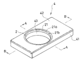
- FIG. 1 is an exploded perspective view of a cup holder including an illumination device according to an embodiment of the present invention.
- FIG. 2 is a perspective view of the cup holder.
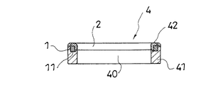
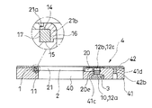
- FIG. 3 is a cross-sectional view taken along the line AA in FIG. 4 is a cross-sectional view and a partially enlarged cross-sectional view taken along the line BB in FIG.
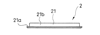
- FIG. 5 is a bottom view of a configuration example (first example) of a diffusion cover constituting the illumination device.
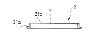
- FIG. 6 is a side view of the first example of the diffusion cover.
- FIG. 7 is a side view of the first example of the diffusion cover, and shows the diffusion cover as viewed from a direction different from FIG. 6 by 90 degrees.
- FIG. 1 is an exploded perspective view of a cup holder including an illumination device according to an embodiment of the present invention.
- FIG. 2 is a perspective view of the cup holder.
- FIG. 3 is a cross-sectional view taken along the line AA in FIG. 4 is
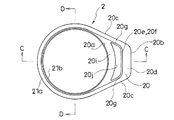
- FIG. 8 is a cross-sectional view taken along the line CC in FIG.
- FIG. 9 is a cross-sectional view taken along the line DD in FIG.
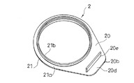
- FIG. 10 is a perspective view of a first example of the diffusion cover.
- FIG. 11 is a perspective view of a configuration example (second example) of the diffusion cover that constitutes the illumination device.
- FIG. 12 is a perspective view of a configuration example (third example) of the diffusion cover that constitutes the illumination device.
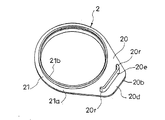
- FIG. 13 is a perspective view of a configuration example (fourth example) of a diffusion cover constituting the illumination device.
- FIG. 14 is a perspective view of a configuration example (fifth example) of the diffusion cover that constitutes the illumination device.
- FIG. 15 is a perspective view of a configuration example (sixth example) of the diffusion cover that constitutes the illumination device.
- FIG. 16 is a perspective view and a partially enlarged perspective view of another configuration example of the light guide constituting the lighting device, and shows the light guide as viewed from the back side.
- the illuminating device includes a light guide 1 having a circular shape, and the light guide 1 forms a portion that shines in a ring shape on a part of various articles.
- such an illumination device is provided in a cup holder 4 of a cup holder used as an interior product such as an automobile.
- the cup holder 4 having a disk shape is provided with a circular hole 40, and a drink container is received in the hole 40 from the bottom side and held therein.
- the illuminating device shines the edge of the hole 40 of the cup holder 4 over its entire circumference to enhance the design of the cup holder, and at the same time, the drink container is placed in the hole 40 of the cup holder 4 at night. It will definitely be able to fit from the bottom.
- Such an illuminating device includes a light guide 1 and a diffusion cover 2.
- the light guide 1 and the diffusion cover 2 are housed in the cup holder 4 so as to be sandwiched between the lower plate 41 and the upper plate 42 constituting the cup holder 4. It is like that.
- the light guide 1 has a circular shape with a light incident portion 10 in one place, and propagates incident light to shine the whole.
- the light guide 1 may have any function as long as it has a function of transmitting light and propagating incident incident light to make the whole shine, and is made of a known light-transmitting material having such a function. be able to.
- the light guide 1 includes an arcuate part 11 along a circular arc of a virtual circle (not shown), a straight part 12, and two arms that connect the arcuate part 11 and the straight part 12. Parts 13 and 13.
- the light guide 1 includes a front surface 14 and a back surface 15 along a virtual plane orthogonal to a rotation center axis (not shown), and an inner side surface 16 and an inner side surface 16 in a direction along the rotation center axis.
- the outer surface 17 is provided on the opposite side, and the cross-sectional shape is substantially rectangular at any position.
- the straight portion 12 is formed outside the virtual circle along a virtual second straight line L2 that is parallel to the virtual first straight line L1 passing through the center x of the virtual circle.
- the total length of the straight portion 12 is smaller than the diameter of the virtual circle.
- the incident portion 10 is formed at a position approximately in the middle of the straight portion 12 in the length direction.
- the protruding end surface of the table-like protruding portion 12 a protruding from the straight portion 12 on the back surface 15 side of the light guide 1 functions as the incident portion 10.
- a V-shaped groove 12b is formed on the surface 14 side of the light guide 1 and at a position directly above the incident portion 10 along a virtual third straight line L3 orthogonal to the second straight line L2. Incident light incident from the incident portion 10 is reflected by the groove wall 12 c of the V-shaped groove 12 b and propagates to the arc-shaped portion 11 through the arm portion 13.
- the light guide 1 has two arm portions 13 and 13. One of the two arm portions 13, 13 connects one end of the straight portion 12 and one end of the arc-shaped portion 11, and the other of the two arm portions 13, 13 connects the other end of the straight portion 12 and the other end of the arc-shaped portion 11. Connected.
- the arc-shaped portion 11 has a total length along a range exceeding 180 degrees of the arc of the virtual circle, and the distance between both ends thereof is smaller than the diameter of the virtual circle and larger than the total length of the straight portion 12. . Therefore, the distance between the two arm portions 13, 13 is gradually reduced as the straight portion 12 is approached.
- the light guide 1 includes a corner portion 18 between the arc-shaped portion 11 and the straight portion 12 (FIG. 1).
- the diffusing cover 2 is disposed on a side different from the light source 3 with respect to the incident part 10, in this embodiment, on a side opposite to the light source 3, and with respect to the incident part 10 with the light guide 1 interposed therebetween. Arranged on the side opposite to the light source 3, the light generated from the light guide 1 is diffused. (FIGS. 3 and 4)
- the diffusion cover 2 is made of a known material that transmits light but makes the transmitted light uniform and uniform, that is, diffused light. Typically, such a diffusion cover 2 is milky white.
- the diffusion cover 2 includes a plate-like base 20 that covers at least the incident portion 10 side of the light guide 1 from the surface 14 side of the light guide 1 and an outer peripheral portion integrated with the plate-like base 20.
- An annular portion 21 that covers the remaining portion of the light guide 1 from at least the surface 14 side thereof is provided.
- the plate-like base portion 20 has no hole or the like penetrating the plate-like base portion 20 in the front-back direction, and is configured to cover the light incident body 10 side of the light guide 1 from the surface 14 side without a gap.
- the annular portion 21 has an annular shape along the virtual circular arc.
- the annular portion 21 includes a first portion 21 a that covers the surface 14 of the light guide 1 along a virtual plane orthogonal to the rotation center axis of the light guide 1, and the light guide in a direction along the rotation center axis. And a second portion 21 b covering the side surface of the body 1.
- the cross section of the annular portion 21 has an L shape due to the first portion 21a and the second portion 21b.
- the outer diameter of the second portion 21b substantially coincides with the diameter of the virtual circle.
- the second portion 21b covers the entire inner surface 16 of the arc-shaped portion 11 of the light guide 1 over its entirety.
- the first portion 21a covers the entire surface 14 of the arcuate portion 11 of the light guide 1 over the entire surface.
- the plate-like base portion 20 includes an arc-shaped side 20a along the virtual circular arc, a straight side 20b having substantially the same length as the straight portion 12 of the light guide 1, and the arc-shaped side.
- the two sides 20c and 20c are provided between 20a and the straight side 20b, and the two sides 20c and 20c gradually reduce the width of the plate-like base 20 as they approach the straight part 12, respectively. It is an inclined side.
- the plate-like base portion 20 covers the two arm portions 13 and the straight portion 12 on the surface 14 side of the light guide 1.
- the back surface 20 d of the plate-like base portion 20 of the diffusion cover 2, which is located between the incident portion 10 and the annular portion 21 of the light guide 1, A partition portion 20e having a rib shape is formed. Further, the partition portion 20e includes a first wall portion 20f extending in a direction crossing the protruding direction y (see FIG. 10) of the plate-like base portion 20 from the annular portion 21, and a terminal of the first wall portion 20f and the annular portion 21.
- the second wall portion 20g is connected to the second portion 21b.
- the plate-like base portion 20 has a plate shape continuous with the first portion 21a of the annular portion 21 and includes the partition portion 20e on the back surface 20d thereof.
- the protruding end 20h of the partition portion 20e is flush with the protruding end 21c of the second portion 21b of the annular portion 21.
- the first wall portion 20 f of the partition portion 20 e is parallel to the straight side 20 b of the plate-like base portion 20.
- the first wall portion 20 f is configured so that its outer surface is in contact with the inner side surface 16 of the straight portion 12 of the light guide 1 to cover it.
- the second wall portion 20g is configured so that its outer surface is in contact with the inner side surface 16 of the arm portion 13 of the light guide 1 to cover it. That is, the second portion 21 b of the annular portion 21 and the partition portion 20 e of the plate-like base portion 20 in the diffusion cover 2 have a contour shape substantially equal to the contour shape of the inner surface 16 of the light guide 1. Further, the outer edges of the annular portion 21 and the plate-like base portion 20 are positioned outside the outer surfaces of these 20f, 20g, and 21b by a dimension that covers the surface 14 of the light guide 1.
- an arc-shaped wall 20j facing the inner surface side of the first wall portion 20f is formed on the outer side of the arc-shaped side 20a of the plate-like base portion 20, and the arc-shaped side 20a, the arc-shaped wall 20j, and two second portions are formed.
- the portion surrounded by the wall portion 20g is a thick portion 20i that increases the front and back dimensions of the plate-like base portion 20.
- a bent portion 20r having a shape aligned with the corner portion 18 (see FIG. 1) of the light guide 1 is formed between the first wall portion 20f and the second wall portion 20g.
- the bent portion 20r is in contact with and covers the corner portion 18 of the light guide 1.
- FIG. 11 shows a back surface 20 d of the plate-like base 20, a first outer surface 20 m in contact with the inner surface 16 of the straight portion 12 of the light guide 1, and a second outer surface 20 n in contact with the inner surface of the arm portion 13 of the light guide 1.
- a second example of the diffusion cover 2 is shown in which a thick portion 20k in which a portion 20p facing the first outer surface 20m is integrated with a second portion 21b of the annular portion 21 is formed. Light emitted from the inner surface of the straight portion 12 of the light guide 1 toward the circumferential central axis of the light guide 1 is diffused by the thick portion 20k.
- FIG. 12 only the rib-like partitioning portion 20 e that is parallel to the straight side 20 b of the plate-like base portion 20 is provided on the back surface 20 d of the plate-like base portion 20.
- the 3rd example of the diffusion cover 2 made to contact an inner surface is shown.
- FIG. 13 the partition 20 e provided on the back surface 20 d of the plate-like base 20 is aligned with the rib-like portion parallel to the straight side 20 b of the plate-like base 20 and the corner 18 of the light guide 1.
- a fourth example of the diffusion cover 2 is shown in which a bent portion 20r having a curved shape is provided, and the partition portion 20e is in contact with the inner surface of the straight portion 12 and the inner surface of the corner portion 18 of the light guide 1. ing.
- the light incident on the light guide 1 from the incident part 10 is concentrated at the corner part 18 and the brightness is increased. However, the light at the corner part 18 is effectively diffused by the bent part 20r covering the corner part 18. It becomes possible.
- FIG. 14 shows a back surface 20 d of the plate-like base 20, a first wall portion 20 f that is parallel to the straight side 20 b of the plate-like base portion 20, an end of the first wall portion 20 f, and a second portion 21 b of the annular portion 21.
- the outer surface of the first wall portion 20f is in contact with the inner surface 16 of the straight portion 12 of the light guide 1
- the outer surface of the second wall portion 20g is of the light guide 1.
- diffusion cover 2 made to contact the inner surface 16 of the arm part 13 is shown.
- the thick portion 20i as in the first example is not provided.
- FIG. 15 shows a back surface 20d of the plate-like base portion 20, a first wall portion 20f that is parallel to the straight side 20b of the plate-like base portion 20, a terminal of the first wall portion 20f, and a second portion 21b of the annular portion 21.
- a recess 41b is formed on the surface 41a of the lower plate 41 constituting the cup holder 4 so as to follow the outer shape of the light guide 1.
- the recess 41b has a recess 41b.
- the hole 40 of the cup holder 4 is formed.
- a through hole 41c is formed in the recess 41b to accommodate the incident portion 10 of the light guide 1 so that the light source 3 constituting the illumination device is fitted into the through hole 41c from the back surface side of the lower plate 41. It has become. (See FIG. 4)
- the light source 3 is an LED.
- the light guide 1 is placed in the recess 41 b of the lower plate 41 having a shape complementary to the outer shape of the light guide 1
- the light guide 1 is placed inside the arcuate portion 11 of the light guide 1.
- the diffusion cover 2 is attached so that the second portion 21 b of the annular portion 21 is inserted and the straight portion 12 and the arm portion 13 of the light guide 1 are covered with the plate-like base portion 20.
- the inner diameter of the second portion 21 b of the annular portion 21 of the diffusion cover 2 matches the hole diameter of the hole 40 of the cup holder 4.
- the upper plate 42 is formed with a hole 42a that is larger than the diameter of the hole 40 of the cup holder 4 and slightly smaller than the outer diameter of the annular portion 21 of the diffusion cover 2, as described above.
- FIG. 4 By attaching the upper plate 42 such that the hole 42a of the upper plate 42 is communicated with the hole 40 of the cup holder 4 from the state where the diffusion cover 2 is attached to the surface 41a of the lower plate 41, An illumination device is built in the cup holder 4.
- reference numeral 42 b in the figure is a boss portion formed on the back side of the upper plate 42, and the boss portion 42 b is inserted into the receiving hole 41 d of the boss portion 42 b formed in the lower plate 41. Therefore, the upper plate 42 and the lower plate 41 are combined with the lighting device interposed therebetween by screwing a tapping screw (not shown) into the boss portion 42b from the back side of the lower plate 41.
- the light guide body 1 When light is incident on the light guide body 1 simply having a circular shape to make the entire light guide body 1 shine, the incident portion 10 becomes bright and the entire light guide body 1 is made uniform. However, according to the diffusion cover 2, the light on the incident portion 10 side is effectively diffused so that the annular portion 21 of the diffusion cover 2 shines with as uniform brightness as possible at any position. Can be. In the illustrated example, the annular portion 21 of the diffusion cover 2 can illuminate the hole of the cup holder 4 with uniform brightness at each position in the circumferential direction. As shown in FIG. 16, the light guide 1 includes an arcuate portion 11, a straight portion 12, and a space s between the straight portion 12 outside the straight portion 12 and the straight portion 12.
- the outer straight portion 12 ′ arranged so as to be parallel to each other and the outer arm portion 13 ′ connecting the straight portion 12 and the outer straight portion 12 ′ are provided, and the incident portion 10 is formed on the outer straight portion 12 ′.
- the rib 19a it is preferable to provide the rib 19a.
- the ribs 19 a can effectively cause the light incident from the incident portion 10 into the light guide 1 to wrap around the straight portion 12.
Landscapes
- Physics & Mathematics (AREA)
- Engineering & Computer Science (AREA)
- Mechanical Engineering (AREA)
- General Physics & Mathematics (AREA)
- Optics & Photonics (AREA)
- General Engineering & Computer Science (AREA)
- Electromagnetism (AREA)
- Thermal Sciences (AREA)
- Transportation (AREA)
- Planar Illumination Modules (AREA)
- Arrangements Of Lighting Devices For Vehicle Interiors, Mounting And Supporting Thereof, Circuits Therefore (AREA)
- Non-Portable Lighting Devices Or Systems Thereof (AREA)
Abstract
Description
前記入射部に対する光源側と異なる側に配されて、前記導光体から生じる光を拡散させる拡散カバーとを有しており、
前記拡散カバーは、前記導光体における前記入射部側を覆う板状基部と、外周部を前記板状基部に一体化させて前記導光体のその余の箇所を覆う環状部とを備えてなるものとした。
この場合さらに、前記導光体を、仮想の円の円弧に沿った弧状部と、前記仮想の円の外側においてこの仮想の円の中心を通る仮想の直線に平行をなす真直部と、両者間に位置されるコーナー部とを備えたものとすると共に、前記拡散カバーの仕切り部が、前記コーナー部に整合した形状の屈曲部を備えたものとしておくことが、この発明の好ましい態様の一つである。
すなわち、この実施の形態にあっては、前記導光体1は、前記弧状部11と、前記真直部12との間にコーナー部18を備えたものとなっている(図1)。
図13は、板状基部20の裏面20dに設けられた仕切り部20eが、板状基部20の真直辺20bに平行をなすリブ状をなす部分と、前記導光体1のコーナー部18に整合した形状を持った屈曲部20rとを備えるようにし、この仕切り部20eを導光体1の真直部12の内面及びコーナー部18の内面に接しさせるようにした拡散カバー2の第四例を示している。前記コーナー部18は入射部10より導光体1内に入射される光が集中し輝度が高くなるが、このコーナー部18を覆う屈曲部20rによってこのコーナー部18の光を効果的に拡散させることが可能となる。
なお、図16に示されるように、導光体1を弧状部11と、真直部12と、この真直部12の外側においてこの真直部12との間に空間sを開けてこの真直部12と平行をなすように配される外側真直部12’と、真直部12と外側真直部12’とをつなぐ外側腕部13’とを備えた態様とすると共に、外側真直部12’に入射部10を備えさせるようにした場合、導光体1の裏面15であって外側腕部12’と真直部12との間のコーナー部19にこのコーナー部19における前記空間s側の縁部を縁取るようにリブ19aを設けておくことが好ましい。このようにした場合、かかるリブ19aによって入射部10より導光体1内に入射される光を真直部12に効果的に回り込ませることが可能となる。
なお、2013年9月18日に出願された日本国特願2013-193367号の明細書、特許請求の範囲、図面及び要約書の全内容をここに引用し、本発明の明細書の開示として、取り入れるものである。
Claims (5)
- 一箇所に光の入射部を備えた周回状をなし、入射光を伝播して全体を輝かせる導光体と、
前記入射部に対する光源側と異なる側に配されて、前記導光体から生じる光を拡散させる拡散カバーとを有しており、
前記拡散カバーは、前記導光体における前記入射部側を覆う板状基部と、外周部を前記板状基部に一体化させて前記導光体のその余の箇所を覆う環状部とを備えてなる、照明装置。 - 拡散カバーの環状部は、導光体の周回中心軸に直交する仮想の平面に沿った前記導光体の表面を覆う第一部分と、前記周回中心軸に沿う向きにある前記導光体の側面を覆う第二部分とを備えてなる、請求項1に記載の照明装置。
- 拡散カバーの板状基部の裏面であって、導光体の入射部と環状部との間に位置される箇所に、リブ状をなす仕切り部が形成されている、請求項2に記載の照明装置。
- 導光体は、仮想の円の円弧に沿った弧状部と、前記仮想の円の外側においてこの仮想の円の中心を通る仮想の直線に平行をなす真直部と、両者間に位置されるコーナー部とを備えており、
拡散カバーの仕切り部は、前記コーナー部に整合した形状の屈曲部を備えている、請求項3に記載の照明装置。 - 拡散カバーの仕切り部は、環状部からの板状基部の突き出し方向に交叉する向きに延びる第一壁部と、第一壁部の端末と環状部の第二部分とを連接させる第二壁部とを備えている、請求項3に記載の照明装置。
Priority Applications (5)
| Application Number | Priority Date | Filing Date | Title |
|---|---|---|---|
| JP2015537871A JP6058808B2 (ja) | 2013-09-18 | 2014-09-09 | 照明装置 |
| CN201480051196.5A CN105556203B (zh) | 2013-09-18 | 2014-09-09 | 照明装置 |
| EP14846005.8A EP3064828B1 (en) | 2013-09-18 | 2014-09-09 | Illumination device |
| US14/916,451 US10351056B2 (en) | 2013-09-18 | 2014-09-09 | Illumination device |
| KR1020167006260A KR101812430B1 (ko) | 2013-09-18 | 2014-09-09 | 조명 장치 |
Applications Claiming Priority (2)
| Application Number | Priority Date | Filing Date | Title |
|---|---|---|---|
| JP2013193367 | 2013-09-18 | ||
| JP2013-193367 | 2013-09-18 |
Publications (1)
| Publication Number | Publication Date |
|---|---|
| WO2015041104A1 true WO2015041104A1 (ja) | 2015-03-26 |
Family
ID=52688755
Family Applications (1)
| Application Number | Title | Priority Date | Filing Date |
|---|---|---|---|
| PCT/JP2014/073824 Ceased WO2015041104A1 (ja) | 2013-09-18 | 2014-09-09 | 照明装置 |
Country Status (7)
| Country | Link |
|---|---|
| US (1) | US10351056B2 (ja) |
| EP (1) | EP3064828B1 (ja) |
| JP (1) | JP6058808B2 (ja) |
| KR (2) | KR101638692B1 (ja) |
| CN (1) | CN105556203B (ja) |
| TW (1) | TWI563203B (ja) |
| WO (1) | WO2015041104A1 (ja) |
Cited By (1)
| Publication number | Priority date | Publication date | Assignee | Title |
|---|---|---|---|---|
| JP2018125146A (ja) * | 2017-01-31 | 2018-08-09 | パナソニックIpマネジメント株式会社 | 導光体、照明装置、電子機器 |
Families Citing this family (8)
| Publication number | Priority date | Publication date | Assignee | Title |
|---|---|---|---|---|
| TWI563203B (en) * | 2013-09-18 | 2016-12-21 | Nifco Inc | Illumination device |
| CN105864721B (zh) * | 2015-01-24 | 2019-05-21 | 鸿富锦精密工业(武汉)有限公司 | 面板导光装置 |
| US10386566B2 (en) * | 2015-05-28 | 2019-08-20 | Nifco Inc. | Vehicle cup-holder with illuminating light guide |
| DE102015011904B4 (de) * | 2015-09-11 | 2026-03-26 | MENTOR GmbH & Co Präzisions-Bauteile KG | Beleuchtungsvorrichtung mit einer ebenen Lichtleiterplatte |
| KR102537126B1 (ko) * | 2017-11-06 | 2023-05-26 | 엘지이노텍 주식회사 | 램프 모듈 |
| CN111506604B (zh) * | 2019-01-31 | 2023-06-13 | 伊姆西Ip控股有限责任公司 | 访问数据的方法、装置和计算机程序产品 |
| JP7360965B2 (ja) * | 2020-02-05 | 2023-10-13 | スタンレー電気株式会社 | カップホルダー |
| DE102021003150B3 (de) | 2021-06-18 | 2022-10-27 | Mercedes-Benz Group AG | Beleuchtungsvorrichtung mit Ringlichtleiter und Fahrzeug mit einer solchen Beleuchtungsvorrichtung |
Citations (3)
| Publication number | Priority date | Publication date | Assignee | Title |
|---|---|---|---|---|
| JP2003297108A (ja) | 2002-04-02 | 2003-10-17 | Bridgestone Corp | リング状発光体 |
| JP2004134223A (ja) * | 2002-10-10 | 2004-04-30 | Alps Electric Co Ltd | 導光材および照明装置 |
| JP2005329753A (ja) * | 2004-05-18 | 2005-12-02 | Kojima Press Co Ltd | カップホルダ |
Family Cites Families (25)
| Publication number | Priority date | Publication date | Assignee | Title |
|---|---|---|---|---|
| FR2732655B1 (fr) | 1995-04-05 | 1997-06-20 | Magneti Marelli France | Dispositif d'eclairage d'indicateur et tableau de bord incorporant celui-ci |
| US6910783B2 (en) * | 2002-10-04 | 2005-06-28 | Lumitex, Inc. | Transparent light emitting members and method of manufacture |
| JP2005178497A (ja) * | 2003-12-18 | 2005-07-07 | Calsonic Kansei Corp | 車両用開閉機構部品 |
| US7127163B2 (en) * | 2004-08-19 | 2006-10-24 | Eastman Kodak Company | Ring light guide |
| TWI317829B (en) * | 2004-12-15 | 2009-12-01 | Epistar Corp | Led illumination device and application thereof |
| CZ2005448A3 (cs) * | 2005-07-13 | 2007-02-14 | Short Images, S. R. O. | Kruhový nástavec fotoblesku |
| DE102005035282A1 (de) | 2005-07-28 | 2007-02-01 | Fischer Automotive Systems Gmbh | Anordnung zur Beleuchtung eines Funktionselements in Kraftfahrzeugen |
| US7766293B2 (en) * | 2006-04-25 | 2010-08-03 | Raffel Systems, Llc | Lighted cup holder for seating arrangements |
| US7500443B1 (en) * | 2007-04-16 | 2009-03-10 | Donald Terry Allen | Holder for a containerized beverage |
| US20080266853A1 (en) * | 2007-04-27 | 2008-10-30 | Tyco Electronics Canada Ltd. | Lighting assembly |
| US7712907B2 (en) * | 2008-03-19 | 2010-05-11 | Zyka Dalibor | Ring flash adapter |
| JP2010132201A (ja) * | 2008-12-05 | 2010-06-17 | Inoac Corp | 容器ホルダ |
| EP2440840A4 (en) | 2009-06-12 | 2016-08-24 | Federal Mogul Corp | DISTRIBUTED LIGHTING ARRANGEMENT |
| DE102009027792B4 (de) * | 2009-07-17 | 2012-11-08 | Lisa Dräxlmaier GmbH | Beleuchtungseinrichtung mit einem Lichtleiter und Innenausstattungsteil für ein Fahrzeug mit einer derartigen Beleuchtungseinrichtung |
| CN102109129B (zh) | 2009-12-29 | 2013-11-06 | 鸿富锦精密工业(深圳)有限公司 | 环形导光结构及采用该环形导光结构的背光模组 |
| BR112012019296A2 (pt) * | 2010-02-01 | 2020-11-03 | Federal-Mogul Ignition Company | conjunto de porta copos iluminado para veículos. |
| CN103257392A (zh) * | 2010-11-23 | 2013-08-21 | 吴明番 | 一种覆盖有扩散膜层的导光体 |
| JP5274719B2 (ja) * | 2011-04-07 | 2013-08-28 | オリンパスメディカルシステムズ株式会社 | 内視鏡及び内視鏡用照明装置 |
| US8770775B2 (en) * | 2012-03-28 | 2014-07-08 | Toyota Motor Engineering & Manufacturing North America, Inc. | Lighted cup holder assembly |
| JP6257132B2 (ja) * | 2012-10-15 | 2018-01-10 | 小島プレス工業株式会社 | 導光体装置 |
| JP5955739B2 (ja) * | 2012-10-16 | 2016-07-20 | カルソニックカンセイ株式会社 | ライトガイド装置 |
| JP5553881B2 (ja) * | 2012-11-19 | 2014-07-16 | 小島プレス工業株式会社 | 車両用カップホルダ |
| TWI563203B (en) * | 2013-09-18 | 2016-12-21 | Nifco Inc | Illumination device |
| US10232769B2 (en) * | 2014-01-08 | 2019-03-19 | Ford Global Technologies, Llc | Vehicle cup holder assembly |
| JP6406151B2 (ja) * | 2015-07-24 | 2018-10-17 | 豊田合成株式会社 | 照明部材 |
-
2014
- 2014-08-29 TW TW103129819A patent/TWI563203B/zh not_active IP Right Cessation
- 2014-09-02 KR KR1020140116285A patent/KR101638692B1/ko active Active
- 2014-09-09 WO PCT/JP2014/073824 patent/WO2015041104A1/ja not_active Ceased
- 2014-09-09 EP EP14846005.8A patent/EP3064828B1/en active Active
- 2014-09-09 KR KR1020167006260A patent/KR101812430B1/ko active Active
- 2014-09-09 CN CN201480051196.5A patent/CN105556203B/zh active Active
- 2014-09-09 JP JP2015537871A patent/JP6058808B2/ja active Active
- 2014-09-09 US US14/916,451 patent/US10351056B2/en active Active
Patent Citations (3)
| Publication number | Priority date | Publication date | Assignee | Title |
|---|---|---|---|---|
| JP2003297108A (ja) | 2002-04-02 | 2003-10-17 | Bridgestone Corp | リング状発光体 |
| JP2004134223A (ja) * | 2002-10-10 | 2004-04-30 | Alps Electric Co Ltd | 導光材および照明装置 |
| JP2005329753A (ja) * | 2004-05-18 | 2005-12-02 | Kojima Press Co Ltd | カップホルダ |
Non-Patent Citations (1)
| Title |
|---|
| See also references of EP3064828A4 |
Cited By (1)
| Publication number | Priority date | Publication date | Assignee | Title |
|---|---|---|---|---|
| JP2018125146A (ja) * | 2017-01-31 | 2018-08-09 | パナソニックIpマネジメント株式会社 | 導光体、照明装置、電子機器 |
Also Published As
| Publication number | Publication date |
|---|---|
| EP3064828A4 (en) | 2017-05-17 |
| US20160195661A1 (en) | 2016-07-07 |
| KR20150032469A (ko) | 2015-03-26 |
| KR101812430B1 (ko) | 2017-12-26 |
| US10351056B2 (en) | 2019-07-16 |
| TWI563203B (en) | 2016-12-21 |
| JP6058808B2 (ja) | 2017-01-11 |
| KR101638692B1 (ko) | 2016-07-11 |
| EP3064828A1 (en) | 2016-09-07 |
| JPWO2015041104A1 (ja) | 2017-03-02 |
| CN105556203A (zh) | 2016-05-04 |
| KR20160040714A (ko) | 2016-04-14 |
| EP3064828B1 (en) | 2018-11-28 |
| CN105556203B (zh) | 2019-04-02 |
| TW201520463A (zh) | 2015-06-01 |
Similar Documents
| Publication | Publication Date | Title |
|---|---|---|
| JP6058808B2 (ja) | 照明装置 | |
| KR101684117B1 (ko) | 차량용 무드등 | |
| JP6257132B2 (ja) | 導光体装置 | |
| US8764260B2 (en) | Light-guiding cover and illumination device having the same | |
| JP2017041368A (ja) | 導光体及びこれを用いた車両用灯具 | |
| JP2011222377A (ja) | 自動車用灯具 | |
| JP2009143409A (ja) | 車両用室内照明装置 | |
| JP2016207396A (ja) | 光源ユニット及び照明器具 | |
| JP2014053151A (ja) | 車両用灯具 | |
| JP5775607B2 (ja) | 車室内照明装置システム | |
| US20060193147A1 (en) | Light guide and illumination apparatus | |
| JP2017041370A (ja) | 導光体及びこれを用いた車両用灯具 | |
| EP3361144B1 (en) | Lighting device | |
| JP6496995B2 (ja) | インジケータ | |
| JP2013109863A (ja) | 車両用灯具 | |
| CN102029942B (zh) | 汽车车厢内照明装置 | |
| WO2016158355A1 (ja) | 照明装置付車両用内装材 | |
| JP2017054630A (ja) | 車両のクリアランスランプ構造 | |
| KR101917048B1 (ko) | 조명장치 및 서랍장치 | |
| TWI624962B (zh) | Illuminating device | |
| JP6314540B2 (ja) | 光源ユニットおよび照明器具 | |
| JP2018018599A (ja) | 照明装置及び天井用照明装置 | |
| JP2023180578A (ja) | 車両用照明装置 | |
| JP2021018874A5 (ja) | ||
| WO2016084737A1 (ja) | 照明装置、及び抽斗装置 |
Legal Events
| Date | Code | Title | Description |
|---|---|---|---|
| WWE | Wipo information: entry into national phase |
Ref document number: 201480051196.5 Country of ref document: CN |
|
| 121 | Ep: the epo has been informed by wipo that ep was designated in this application |
Ref document number: 14846005 Country of ref document: EP Kind code of ref document: A1 |
|
| ENP | Entry into the national phase |
Ref document number: 2015537871 Country of ref document: JP Kind code of ref document: A |
|
| WWE | Wipo information: entry into national phase |
Ref document number: 14916451 Country of ref document: US |
|
| REEP | Request for entry into the european phase |
Ref document number: 2014846005 Country of ref document: EP |
|
| WWE | Wipo information: entry into national phase |
Ref document number: 2014846005 Country of ref document: EP |
|
| ENP | Entry into the national phase |
Ref document number: 20167006260 Country of ref document: KR Kind code of ref document: A |
|
| NENP | Non-entry into the national phase |
Ref country code: DE |