WO2015041249A1 - 蓄電システム及び蓄電システムの保全方法 - Google Patents
蓄電システム及び蓄電システムの保全方法 Download PDFInfo
- Publication number
- WO2015041249A1 WO2015041249A1 PCT/JP2014/074557 JP2014074557W WO2015041249A1 WO 2015041249 A1 WO2015041249 A1 WO 2015041249A1 JP 2014074557 W JP2014074557 W JP 2014074557W WO 2015041249 A1 WO2015041249 A1 WO 2015041249A1
- Authority
- WO
- WIPO (PCT)
- Prior art keywords
- signal
- storage battery
- maintenance
- panel
- mask
- Prior art date
- Legal status (The legal status is an assumption and is not a legal conclusion. Google has not performed a legal analysis and makes no representation as to the accuracy of the status listed.)
- Ceased
Links
Images




Classifications
-
- H—ELECTRICITY
- H01—ELECTRIC ELEMENTS
- H01M—PROCESSES OR MEANS, e.g. BATTERIES, FOR THE DIRECT CONVERSION OF CHEMICAL ENERGY INTO ELECTRICAL ENERGY
- H01M10/00—Secondary cells; Manufacture thereof
- H01M10/42—Methods or arrangements for servicing or maintenance of secondary cells or secondary half-cells
- H01M10/48—Accumulators combined with arrangements for measuring, testing or indicating the condition of cells, e.g. the level or density of the electrolyte
- H01M10/482—Accumulators combined with arrangements for measuring, testing or indicating the condition of cells, e.g. the level or density of the electrolyte for several batteries or cells simultaneously or sequentially
-
- H—ELECTRICITY
- H01—ELECTRIC ELEMENTS
- H01M—PROCESSES OR MEANS, e.g. BATTERIES, FOR THE DIRECT CONVERSION OF CHEMICAL ENERGY INTO ELECTRICAL ENERGY
- H01M10/00—Secondary cells; Manufacture thereof
- H01M10/42—Methods or arrangements for servicing or maintenance of secondary cells or secondary half-cells
- H01M10/4207—Methods or arrangements for servicing or maintenance of secondary cells or secondary half-cells for several batteries or cells simultaneously or sequentially
-
- H—ELECTRICITY
- H01—ELECTRIC ELEMENTS
- H01M—PROCESSES OR MEANS, e.g. BATTERIES, FOR THE DIRECT CONVERSION OF CHEMICAL ENERGY INTO ELECTRICAL ENERGY
- H01M10/00—Secondary cells; Manufacture thereof
- H01M10/42—Methods or arrangements for servicing or maintenance of secondary cells or secondary half-cells
- H01M10/425—Structural combination with electronic components, e.g. electronic circuits integrated to the outside of the casing
-
- H—ELECTRICITY
- H01—ELECTRIC ELEMENTS
- H01M—PROCESSES OR MEANS, e.g. BATTERIES, FOR THE DIRECT CONVERSION OF CHEMICAL ENERGY INTO ELECTRICAL ENERGY
- H01M10/00—Secondary cells; Manufacture thereof
- H01M10/42—Methods or arrangements for servicing or maintenance of secondary cells or secondary half-cells
- H01M10/48—Accumulators combined with arrangements for measuring, testing or indicating the condition of cells, e.g. the level or density of the electrolyte
-
- H—ELECTRICITY
- H02—GENERATION; CONVERSION OR DISTRIBUTION OF ELECTRIC POWER
- H02J—ELECTRIC POWER NETWORKS; CIRCUIT ARRANGEMENTS OR SYSTEMS FOR SUPPLYING OR DISTRIBUTING ELECTRIC POWER; SYSTEMS FOR STORING ELECTRIC ENERGY
- H02J3/00—Circuit arrangements for AC mains or AC distribution networks
- H02J3/28—Arrangements for balancing of the load in networks by storage of energy
- H02J3/32—Arrangements for balancing of the load in networks by storage of energy using batteries or super capacitors with converting means
-
- H—ELECTRICITY
- H02—GENERATION; CONVERSION OR DISTRIBUTION OF ELECTRIC POWER
- H02J—ELECTRIC POWER NETWORKS; CIRCUIT ARRANGEMENTS OR SYSTEMS FOR SUPPLYING OR DISTRIBUTING ELECTRIC POWER; SYSTEMS FOR STORING ELECTRIC ENERGY
- H02J7/00—Circuit arrangements for charging or discharging batteries or for supplying loads from batteries
- H02J7/34—Parallel operation in networks using both storage and other DC sources, e.g. providing buffering
-
- H—ELECTRICITY
- H02—GENERATION; CONVERSION OR DISTRIBUTION OF ELECTRIC POWER
- H02J—ELECTRIC POWER NETWORKS; CIRCUIT ARRANGEMENTS OR SYSTEMS FOR SUPPLYING OR DISTRIBUTING ELECTRIC POWER; SYSTEMS FOR STORING ELECTRIC ENERGY
- H02J7/00—Circuit arrangements for charging or discharging batteries or for supplying loads from batteries
- H02J7/34—Parallel operation in networks using both storage and other DC sources, e.g. providing buffering
- H02J7/35—Parallel operation in networks using both storage and other DC sources, e.g. providing buffering with light sensitive cells
-
- H—ELECTRICITY
- H02—GENERATION; CONVERSION OR DISTRIBUTION OF ELECTRIC POWER
- H02J—ELECTRIC POWER NETWORKS; CIRCUIT ARRANGEMENTS OR SYSTEMS FOR SUPPLYING OR DISTRIBUTING ELECTRIC POWER; SYSTEMS FOR STORING ELECTRIC ENERGY
- H02J7/00—Circuit arrangements for charging or discharging batteries or for supplying loads from batteries
- H02J7/50—Circuit arrangements for charging or discharging batteries or for supplying loads from batteries acting upon multiple batteries simultaneously or sequentially
- H02J7/52—Circuit arrangements for charging or discharging batteries or for supplying loads from batteries acting upon multiple batteries simultaneously or sequentially for charge balancing, e.g. equalisation of charge between batteries
-
- H—ELECTRICITY
- H02—GENERATION; CONVERSION OR DISTRIBUTION OF ELECTRIC POWER
- H02J—ELECTRIC POWER NETWORKS; CIRCUIT ARRANGEMENTS OR SYSTEMS FOR SUPPLYING OR DISTRIBUTING ELECTRIC POWER; SYSTEMS FOR STORING ELECTRIC ENERGY
- H02J7/00—Circuit arrangements for charging or discharging batteries or for supplying loads from batteries
- H02J7/60—Circuit arrangements for charging or discharging batteries or for supplying loads from batteries including safety or protection arrangements
-
- H—ELECTRICITY
- H02—GENERATION; CONVERSION OR DISTRIBUTION OF ELECTRIC POWER
- H02J—ELECTRIC POWER NETWORKS; CIRCUIT ARRANGEMENTS OR SYSTEMS FOR SUPPLYING OR DISTRIBUTING ELECTRIC POWER; SYSTEMS FOR STORING ELECTRIC ENERGY
- H02J7/00—Circuit arrangements for charging or discharging batteries or for supplying loads from batteries
- H02J7/80—Circuit arrangements for charging or discharging batteries or for supplying loads from batteries including monitoring or indicating arrangements
-
- H—ELECTRICITY
- H02—GENERATION; CONVERSION OR DISTRIBUTION OF ELECTRIC POWER
- H02J—ELECTRIC POWER NETWORKS; CIRCUIT ARRANGEMENTS OR SYSTEMS FOR SUPPLYING OR DISTRIBUTING ELECTRIC POWER; SYSTEMS FOR STORING ELECTRIC ENERGY
- H02J9/00—Circuit arrangements for emergency or stand-by power supply, e.g. for emergency lighting
- H02J9/04—Circuit arrangements for emergency or stand-by power supply, e.g. for emergency lighting in which the distribution system is disconnected from the normal source and connected to a standby source
- H02J9/06—Circuit arrangements for emergency or stand-by power supply, e.g. for emergency lighting in which the distribution system is disconnected from the normal source and connected to a standby source with automatic change-over, e.g. UPS systems
- H02J9/061—Circuit arrangements for emergency or stand-by power supply, e.g. for emergency lighting in which the distribution system is disconnected from the normal source and connected to a standby source with automatic change-over, e.g. UPS systems for DC powered loads
-
- H—ELECTRICITY
- H01—ELECTRIC ELEMENTS
- H01M—PROCESSES OR MEANS, e.g. BATTERIES, FOR THE DIRECT CONVERSION OF CHEMICAL ENERGY INTO ELECTRICAL ENERGY
- H01M10/00—Secondary cells; Manufacture thereof
- H01M10/42—Methods or arrangements for servicing or maintenance of secondary cells or secondary half-cells
- H01M10/425—Structural combination with electronic components, e.g. electronic circuits integrated to the outside of the casing
- H01M2010/4271—Battery management systems including electronic circuits, e.g. control of current or voltage to keep battery in healthy state, cell balancing
-
- H—ELECTRICITY
- H01—ELECTRIC ELEMENTS
- H01M—PROCESSES OR MEANS, e.g. BATTERIES, FOR THE DIRECT CONVERSION OF CHEMICAL ENERGY INTO ELECTRICAL ENERGY
- H01M10/00—Secondary cells; Manufacture thereof
- H01M10/42—Methods or arrangements for servicing or maintenance of secondary cells or secondary half-cells
- H01M10/425—Structural combination with electronic components, e.g. electronic circuits integrated to the outside of the casing
- H01M2010/4278—Systems for data transfer from batteries, e.g. transfer of battery parameters to a controller, data transferred between battery controller and main controller
-
- Y—GENERAL TAGGING OF NEW TECHNOLOGICAL DEVELOPMENTS; GENERAL TAGGING OF CROSS-SECTIONAL TECHNOLOGIES SPANNING OVER SEVERAL SECTIONS OF THE IPC; TECHNICAL SUBJECTS COVERED BY FORMER USPC CROSS-REFERENCE ART COLLECTIONS [XRACs] AND DIGESTS
- Y02—TECHNOLOGIES OR APPLICATIONS FOR MITIGATION OR ADAPTATION AGAINST CLIMATE CHANGE
- Y02B—CLIMATE CHANGE MITIGATION TECHNOLOGIES RELATED TO BUILDINGS, e.g. HOUSING, HOUSE APPLIANCES OR RELATED END-USER APPLICATIONS
- Y02B10/00—Integration of renewable energy sources in buildings
- Y02B10/70—Hybrid systems, e.g. uninterruptible or back-up power supplies integrating renewable energies
-
- Y—GENERAL TAGGING OF NEW TECHNOLOGICAL DEVELOPMENTS; GENERAL TAGGING OF CROSS-SECTIONAL TECHNOLOGIES SPANNING OVER SEVERAL SECTIONS OF THE IPC; TECHNICAL SUBJECTS COVERED BY FORMER USPC CROSS-REFERENCE ART COLLECTIONS [XRACs] AND DIGESTS
- Y02—TECHNOLOGIES OR APPLICATIONS FOR MITIGATION OR ADAPTATION AGAINST CLIMATE CHANGE
- Y02E—REDUCTION OF GREENHOUSE GAS [GHG] EMISSIONS, RELATED TO ENERGY GENERATION, TRANSMISSION OR DISTRIBUTION
- Y02E60/00—Enabling technologies; Technologies with a potential or indirect contribution to GHG emissions mitigation
- Y02E60/10—Energy storage using batteries
-
- Y—GENERAL TAGGING OF NEW TECHNOLOGICAL DEVELOPMENTS; GENERAL TAGGING OF CROSS-SECTIONAL TECHNOLOGIES SPANNING OVER SEVERAL SECTIONS OF THE IPC; TECHNICAL SUBJECTS COVERED BY FORMER USPC CROSS-REFERENCE ART COLLECTIONS [XRACs] AND DIGESTS
- Y02—TECHNOLOGIES OR APPLICATIONS FOR MITIGATION OR ADAPTATION AGAINST CLIMATE CHANGE
- Y02P—CLIMATE CHANGE MITIGATION TECHNOLOGIES IN THE PRODUCTION OR PROCESSING OF GOODS
- Y02P90/00—Enabling technologies with a potential contribution to greenhouse gas [GHG] emissions mitigation
- Y02P90/50—Energy storage in industry with an added climate change mitigation effect
Definitions
- the present invention relates to a power storage system using a storage battery and maintenance technology including maintenance thereof.
- a large-scale power storage system capable of charging and discharging a large capacity by connecting a plurality of storage batteries in series and in parallel has been developed.
- the power storage system charges a storage battery by power feeding from an electric power system, a solar power generation system, or the like, and supplies stable and necessary power to a load of a load facility by discharging from the storage battery.
- Examples of uses of large-scale power storage systems include peak cuts and peak shifts of load power at load facilities such as buildings and factories, and leveling of natural energy such as sunlight.
- a lithium ion storage battery As a storage battery used in a power storage system, a lithium ion storage battery is used as an alternative to a conventional lead battery. Depending on conditions such as capacity density and mass, lithium ion batteries are often more advantageous than lead batteries. Unlike a lead battery, a lithium ion storage battery is required to always monitor the state of the storage battery voltage and the like in order to ensure soundness. That is, the power storage system has a function of monitoring the state of the storage battery.
- the above functions determine and detect the status of storage battery normal, abnormal, warning, etc. through monitoring, and send a signal according to the detection. For example, when the voltage of the storage battery is determined to be out of the use range, a signal indicating abnormality is output, and when it is determined that the storage battery voltage is near the threshold value in the use range, a signal indicating warning is output.
- the power storage system outputs an alarm in response to detection of an abnormality or warning of the storage battery, and stops the operation of the system including the corresponding storage battery corresponding to the state, that is, the charge / discharge function.
- Maintenance personnel perform maintenance work such as confirming a defect in a part including the storage battery in accordance with an alarm based on the above signal.
- the maintenance staff solves the problem and ensures safety, and then resumes the operation of the corresponding part.
- Maintenance work includes maintenance activities such as periodic maintenance and inspection, diagnosis and investigation of storage batteries in the above abnormalities and warnings, and parts replacement.
- Patent Document 1 describes a configuration in which a storage battery replacement terminal is provided in a battery system in which a plurality of storage batteries are connected in series and in parallel.
- the storage battery of the conventional example includes a storage battery including the corresponding storage battery according to a detection signal of a state such as an abnormality or a warning due to a failure or deterioration of the storage battery.
- the operation of the system that is, the charge / discharge function is stopped in units of groups.
- Maintenance work including maintenance by maintenance personnel is performed in a state where operation is stopped in units of storage battery groups. Therefore, the state of the stop in the unit of a storage battery group continues until the malfunction of a storage battery is eliminated by maintenance work. During this stoppage time, the storage battery group cannot be used for charging and discharging.
- the storage battery group also has a stop time for normal storage batteries other than abnormal storage batteries.
- Patent Document 1 has no means for dealing with the stop time of the storage battery group based on the monitoring of the storage battery, and there is room for improvement in terms of convenience.
- An object of the present invention is to provide a technology capable of increasing the operating rate of the entire system by shortening the operation stop time in units of storage battery groups during maintenance work including maintenance of storage battery facilities with respect to the above storage system. It is to be.
- a representative embodiment of the present invention is a power storage system and a maintenance method including maintenance of the power storage system, and has the following configuration.
- the power storage system of one embodiment includes one or more relay boards connected to one or more power control devices, a plurality of storage battery boards connected to the relay board and mounted with one or more storage batteries, One or more maintenance devices connected to the relay panel during maintenance work including maintenance by maintenance personnel, and the storage battery panel detects or determines the state based on monitoring of the state of the storage battery 1 signal is transmitted to the upper relay panel, the relay panel transmits a second signal based on the first signal to the upper power control apparatus, and the maintenance apparatus is operated by the maintenance staff.
- a third signal is transmitted to the relay panel above the storage battery panel to be maintained, and the relay panel is in accordance with the third signal and the maintenance target A first signal from the storage battery panel of the Second signal based on the signal, to invalidate masked.
- a storage system maintenance method includes: one or more relay panels connected to one or more power control devices; and a plurality of storage batteries connected to the relay panel and mounted with one or more storage batteries.
- a maintenance method including maintenance of a power storage system comprising a panel and one or more maintenance devices connected to the relay panel during maintenance work including maintenance by maintenance personnel, based on the operation of the maintenance personnel
- the maintenance device transmits a mask start instruction signal to the upper relay board of the storage battery board to be maintained, and the relay board follows the mask start instruction signal from the maintenance battery battery board to the upper relay board.
- a third procedure for canceling and enabling the masking state of the signal or the second signal A third procedure for canceling and enabling the masking state of the signal or the second signal.
- a storage system maintenance method includes: one or more relay panels connected to one or more power control devices; and a plurality of storage batteries connected to the relay panel and mounted with one or more storage batteries.
- a maintenance method for a power storage system comprising a panel and one or more maintenance devices connected to the relay panel during maintenance work including maintenance by maintenance personnel, wherein the storage battery panel allows the storage battery to A first procedure for transmitting a first signal, which is detected or determined based on the status monitoring, to the upper relay panel, and a second signal based on the first signal is transmitted by the relay panel.
- the maintenance device transmits a mask start instruction signal to a relay panel above the storage battery panel to be maintained, and the relay panel according to the mask start instruction signal, Mask the first signal transmitted from the storage battery panel to be maintained to the upper relay panel, or the second signal transmitted from the relay panel to the upper power controller based on the first signal.
- the power control device Based on the fourth procedure to be invalidated and the operation of the maintenance personnel, causes the subordinate relay panel and the plurality of storage battery panels to be disconnected by the power control device in a state where the storage battery panel to be maintained is electrically disconnected.
- Maintenance work related to the storage battery panel to be maintained is performed based on the fifth procedure in which the operation in the unit including the operation is resumed and the operation of the maintenance personnel, and the storage battery panel after the maintenance is electrically connected. 6th procedure and before Based on the operation of the maintenance staff, the maintenance device transmits a mask release instruction signal to a relay panel higher than the storage battery panel to be maintained, and the relay panel follows the mask release instruction signal according to the first mask. A seventh procedure for releasing and enabling the signal or the second signal mask.
- maintenance includes maintenance. That is, the maintenance method of the present embodiment includes a maintenance method.
- Maintenance personnel perform maintenance work while the storage battery group is stopped.
- the maintenance staff checks the storage battery in a state where some trouble such as failure or deterioration has occurred, and performs diagnosis or investigation, replacement of the storage battery or peripheral devices as necessary. After the cause of the malfunction is removed by the maintenance work and a normal state is confirmed, the power storage system restarts the operation of the storage battery group. Until the above problem is solved, the storage battery group continues to be stopped. Even if most of the plurality of storage batteries are in a normal state during the stop time, they cannot be used for charging and discharging.
- the stop time in units of the storage battery group becomes longer, it will be inconvenient for the user. For example, it may take a long time to investigate a malfunction of the storage battery, and the stop time becomes longer.
- the use of the power storage system is that of infrastructure that is directly connected to daily life, it is desirable to shorten the stop time as much as possible and use a storage battery in a normal state as much as possible.
- maintenance work is performed by maintenance personnel, it is desirable that maintenance work can be performed with the storage battery group operating as much as possible to ensure safety.
- the battery system of Patent Document 1 cannot cope with the problem of the stop time when considering application to a configuration for monitoring a storage battery.
- a state such as an abnormality or a warning is detected due to the interruption of communication for monitoring the storage battery.
- the system stops the operation of the part including the replacement storage battery. That is, the stop time of the storage battery group becomes longer during maintenance work.
- the power storage system of the present embodiment shown in FIG. 1 and the like enables maintenance work in the state of operation of the storage battery group during maintenance work including maintenance of the storage battery facility, and realizes shortening of the stop time of the storage battery group. Therefore, as shown in FIG. 2 and the like, the power storage system according to the present embodiment provides a mask function for masking a storage battery monitoring signal based on an operation performed by a maintenance worker on a maintenance device. As shown in FIGS. 5 and 6, the storage system maintenance method according to the present embodiment performs maintenance work with the storage battery group of the storage system in an operating state by the mask function based on the operation of the maintenance device by maintenance personnel. Including the procedure to be performed.
- a storage battery panel is used as an object of maintenance work.
- a mask instruction signal is transmitted from the maintenance device to the relay panel.
- the relay panel receives the signal, the relay panel masks the signal from monitoring the storage battery from the storage battery panel to be maintained and invalidates it.
- a high-order electric power control apparatus can be operated by the unit of the storage battery group containing the storage battery panel of a maintenance object.
- the maintenance staff can perform maintenance work in a state where the corresponding storage battery group other than the storage battery panel to be maintained is operated.
- a feature of the power storage system of the present embodiment is that, in addition to being able to perform the above work, the stop portion in the power storage system can be separated regardless of the form of the upper power control device.
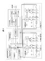
- FIG. 1 shows the overall configuration of the power storage system of the present embodiment.
- the power storage system of the present embodiment includes a plurality of power control devices 1, a plurality of relay panels 2, a plurality of storage battery panels 3, and a maintenance device 5.
- the power storage system of FIG. 1 includes N1 power control devices 1 PCS1 to PCSN1, N2 relay panels R1 to RN2, and N3 storage battery panels 3 L1 to LN3.
- One power control apparatus 1 connects N4 relay panels 2.
- N2 N1 ⁇ N4.
- One relay panel 2 connects N5 storage battery panels 3.
- N3 N2 ⁇ N5.
- N2 all relay panels 2 and N3 all storage battery panels 3 are targets and ranges to which the mask function during maintenance work can be applied.
- PCS unit that is a unit of one power control device 1 and a plurality of relay panels 2 and a plurality of storage battery panels 3 connected thereto, and there are N1 units from C1 to CN1.
- Reference numeral 102 denotes a relay panel unit including one relay panel 2 and a plurality of storage battery panels 3 connected to the relay panel 2, and there are N2 units corresponding to R1 to RN2.
- Reference numeral 103 denotes a storage battery panel unit in which a plurality of battery packs 4 (FIG. 2) by one storage battery panel 3 are grouped, and there are N3 units corresponding to L1 to LN3.
- PCS 1 is configured by a connection from C1, which is the first PCS unit 101 connected to PCS1, to CN1, which is the N1th PCS unit 101 connected to PCSN1.
- the PCS units 101 C1 to CN1 have the same configuration.
- PCS1 to PCSN1 have the same configuration, and it may be considered that one power control device 1 is configured by their connection or integration.
- the outputs of one power control device 1 are connected in parallel according to the required amount of power.
- Each of the PCS1 to PCSN1 supplies power obtained by adding up the power of the PCS unit 101. This power is designed according to the required power of the connected load facility.
- N4 3 relay panels 2 through the main circuit wiring 6.
- three relay boards 2 R1 to R3 are connected to PCS1.
- 10 storage battery panels L1 to L10 are connected in parallel to R1.
- One storage battery board 3 is mounted with a plurality of battery packs 4 (FIGS. 2 and 3).
- b1 to bN6 FIG. 3 which are N6 battery packs 4 are connected in series.
- the power control device 1 is a PCS (Power Conditioning System) and has a function of performing control processing of the power storage system and controlling charging / discharging of the storage battery group connected via the relay panel 2.
- the PCS is connected to an electric power system, a load facility, a solar power generation system, and the like.
- the PCS charges the storage battery with electric power from an electric power system, a solar power generation system, etc., and supplies the electric power generated by the discharge from the storage battery to the load of the load facility.
- the current control device 1 generates an alarm and detects the operation of the PCS unit 101 which is a corresponding lower system part when an abnormality or warning of the storage battery is detected by a signal from the lower relay panel 2. Stop.
- the PCS has a function of converting direct current (DC) and alternating current (AC) power in order to stably adjust and use the power of the storage battery and the power of the photovoltaic power generation.
- An AC inverter is provided.
- the power control device 1 is not necessarily equipped with a specific function, and conventional PCS hardware and software can also be applied. Stopping the operation of the storage battery or the like in the present embodiment means stopping the charging / discharging function. In this stopped state, charging to the storage battery or discharging from the storage battery does not work.
- the maintenance device 5 is connected to the relay panel 5 by the maintenance staff U as necessary for maintenance work.
- the maintenance device 5 is configured in the form of a PC or the like.
- the maintenance device 5 may be configured by a dedicated device or circuit.
- Reference numeral 113 denotes L2, which is an example of the storage battery panel 3 to be maintained.
- Reference numeral 112 denotes R1 which is an example of the relay panel 2 connected to the upper level of the storage battery panel 3 to be maintained. For example, during maintenance work for L2, the maintenance device 5 is connected to R1.
- the connection between the maintenance device 5 and the relay panel 2 (R1) in FIG. 1 is an example, and any of the relay panels 2 can be connected. Further, by providing a plurality of maintenance devices 5, another maintenance device 5 may be connected to each of a plurality of some relay panels 2. One maintenance device 5 may be connected to a plurality of some relay panels 2. A plurality of maintenance personnel may use the maintenance device 5 respectively.
- connection between the constituent elements may be direct connection or indirect connection with other elements interposed therebetween.
- connection between the maintenance device 5 and the relay panel 2 may be a connection with a communication network or a communication device interposed therebetween so that remote operation, that is, remote maintenance is possible.
- the elements such as the power control device 1 and the relay panel 2 have a plurality of configurations, but the configuration is not limited to this, and a configuration with a single device is also possible.
- a system with a single relay panel 2 may be used. It is also possible to have one storage battery mounted on the storage battery panel 3.
- a power storage system without the relay panel 2 is also possible, and in this case, a plurality of storage battery panels 3 are connected to the power control device 1.
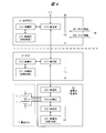
- FIG. 2 shows device connections and functional block configurations of each component of the power storage system of FIG.
- the power control apparatus 1 includes a control unit 11, a communication unit 12, and a power supply connection unit 13.
- the control unit 11 includes a CPU, a memory, and the like, and performs control processing for the power control apparatus 1.
- the communication unit 12 performs communication processing with the communication unit of the overall BCU 21 of the relay panel 2.
- the power supply connection portion 13 is a portion that connects together a plurality of terminals of the parallel connection portion 22 of the relay panel 2 and includes a terminal that inputs and outputs a storage battery voltage.
- the relay panel 2 includes a general BCU 21, a parallel connection unit 22, and a connection unit 23.
- the overall BCU 21 includes a CPU, a memory, and the like, and is a constituent element of the storage battery control unit in the following broad sense.
- the overall BCU 21 is communicatively connected to the control unit 11 of the upper power control apparatus 1 and the BCU 31 of each lower storage battery panel 3.
- the parallel connection unit 22 is an interface unit for connecting a plurality of storage battery panels 3 (for example, L1 to L10) to the relay panel 2 in parallel.
- the parallel connection part 22 includes a terminal for connecting the main circuit wiring of each storage battery panel 3.
- the connection unit 23 is an interface unit that connects the maintenance device 5 to the relay panel 2 and includes, for example, a terminal for connecting a cable.
- the relay panel 2 has functions such as connection, monitoring, and SOC calculation of the plurality of storage battery panels 3.
- the storage battery board 3 includes a plurality of BCUs 31, a plurality of storage battery monitoring units 32, and a battery block 40.
- the BCU 31 includes a CPU, a memory, and the like, and is a component of the storage battery control unit in the following broad sense.
- the battery block 40 includes a plurality of battery packs 4 connected in series, disconnectors 41 at both ends, and a fuse 42 at one end.
- the storage battery panel 3 has functions such as protection, monitoring, and SOC calculation of the battery pack 4.
- the relay panel 2 and the storage battery panel 3 include a storage battery control unit (BCU: battery control unit) in a broad sense.
- the storage battery control unit is composed of a general BCU 21 provided in the relay panel 2 and one or more BCUs 31 provided in each storage battery panel 3.
- the BCU 31 is a lower-order BCU
- the overall BCU 21 is an upper-order BCU.
- the overall BCU 21 communicatively connects a plurality of BCUs 31 and performs overall control of the plurality of BCUs 31.
- the overall BCU 21 comprehensively determines the state of the battery pack 4 group using signals from the plurality of BCUs 31.
- the overall BCU 21 and BCU 31 have an implementation corresponding to the mask function.
- the BCU 31 and the overall BCU 21 are mounted on a circuit board, for example.
- Each BCU 31 has the same configuration.
- one representative BCU 31 is connected to the general BCU 21 of the upper relay panel 2.
- a plurality of storage battery monitoring units 32 are connected to the BCU 31.
- the plurality of storage battery monitoring units 32 function as a monitoring unit for the battery block 40.
- One storage battery monitoring unit 32 monitors and detects states such as voltage, current, and temperature for one or more battery packs 4 in the battery block 40.
- Each storage battery monitoring unit 32 has the same configuration.
- the storage battery monitoring unit 32 may be integrated with the BCU 31.
- the BCU 31 constantly monitors the state of devices and circuits such as the plurality of battery packs 4 of the battery block 40 in the storage battery panel 3 and its peripheral power supply using the plurality of storage battery monitoring units 32.
- the maintenance device 5 includes a control unit 51, a communication unit 52, a connection unit 53, and a screen unit 54.
- the control unit 51 performs control processing of the maintenance device 5.
- the communication unit 52 performs communication processing with the relay panel 2 and the current control device 1 connected through the connection unit 53.
- the connection unit 53 is an interface unit for connection when the maintenance device 5 is connected to the relay panel 2 or the like.
- the connection unit 23 of the relay panel 2 and the connection unit 54 of the maintenance device 5 are connected by a cable, and communication is performed.
- the screen unit 54 configures and provides a screen serving as a user interface for maintenance work by the maintenance worker U based on the control process of the control unit 51.
- the maintenance device 5 performs a process corresponding to a support function at the time of maintenance work including a mask function by the control unit 51, and provides a screen as shown in FIG. Maintenance personnel can input an instruction to start or release the mask on the screen. Thereby, the mask signal M is transmitted from the maintenance device 5 to the relay panel 2.
- F1 indicates a flag signal transmitted from the storage battery panel 3 such as L1 or L2 to the upper relay panel 2 such as R1 based on the monitoring.
- F2 indicates a flag signal transmitted from R1 that is the relay panel 2 to, for example, the PCS1 that is the host power control apparatus 1 based on the flag signal F1.
- R1 that is relay panel 2 transmits flag F2 to PCS1 that is host power control apparatus 1 in a state where flag signal F1 from the storage battery panel that is a mask target is determined to be invalid.
- the host power control apparatus 1 changes the state in which the operation of the PCS unit 101 including the target storage battery panel 3 is not stopped or the state where the operation is resumed from the state where the operation is temporarily stopped.
- FIG. 3 shows a connection configuration of a plurality of storage battery panels 3 and main circuit wiring in the relay panel unit 102.
- a plurality of storage battery panels 3 are connected in parallel to the relay panel 2, for example, R 1 through a switch, a positive main circuit wiring 301 and a negative main circuit wiring 302.
- a plurality of battery cells (FIG. 4) are connected in series by N6 battery packs 4 indicated by b1 to bN6.
- One battery pack 4 includes one or more battery cells 7.
- the battery cells 7 are all lithium ion storage batteries in the present embodiment.
- the configuration inside the storage battery panel 3 is simply shown by only the battery block 40.
- Disconnectors 41 are provided at both ends of the battery block 40.
- the disconnector 41 at one end of the battery block 40 is provided with a fuse 42.
- the disconnector 41 is switched between an on state and an off state in accordance with functions of charge / discharge and storage battery protection.
- the disconnector 41 is turned on and off based on control from the BCU 31 when the battery block 40 is attached and detached.
- the fuse 42 is a protection circuit, and is automatically cut when the voltage difference between the plurality of battery packs 4 is large and the battery is overloaded. In some cases, the fuse 42 can be omitted, and the disconnector 41 can have a function equivalent to the fuse 42.
- the battery block 40 of the plurality of storage battery panels 3 connected in parallel to the relay panel 2 when one battery block 40 fails, it can be operated in a degenerated state by the other plurality of parallel battery blocks 40. is there. If one battery pack 4 of the battery blocks 40, for example, the battery pack 4 indicated by 310 fails, and replacement work in units of the battery blocks 40 is necessary, an abnormality or the like based on monitoring by the storage battery panel 3 Is sent to the upper relay panel 2.
- the battery packs 4 of the plurality of battery blocks 40 connected in parallel to the relay panel 2 need to have values such as voltage and SOC (state of charge or called charge state) as predetermined values. There is. That is, the potential difference and the SOC difference need to be within a predetermined range. If this is not the case, a current exceeding the specified value flows when the battery block 40 is replaced, which is not safe.
- FIG. 1 Example of failure occurrence
- problems such as failure of storage battery equipment in the conventional power storage system, and occurrences of abnormalities and warnings corresponding thereto.
- the conventional power storage system has a storage battery facility similar to that shown in FIG.
- one battery pack 4 for example, 310 in FIG.
- maintenance of one battery block 40 including 310 battery packs 4 at L2 is required.
- a flag signal F1 indicating a state such as abnormality due to the failure is transmitted from the storage battery panel L2 to the upper relay panel 2 R1 by the storage battery monitoring function. Further, a similar flag signal F2 is transmitted from R1 to PCS1, which is the upper power control apparatus 1. Based on the flag signal F2, the PCS 1 stops the operation in the PCS unit 101 of C1 including R1 including L2 together with the output of the alarm. In the state where the PCS unit 101 of C1 is stopped, the total number of the 30 storage battery panels 3 of L1 to L30 is prohibited from being used with respect to the charge / discharge function. Until the trouble of the L2 storage battery panel 3 including the failed battery pack 4 is resolved by the maintenance work of the maintenance personnel, the C1 PCS unit 101 is stopped.
- the power control device can control operation and stop in PCS units.
- the power control devices are connected in parallel, individual relay panel units or storage panel units in the PCS unit storage battery group It is impossible to control charging / discharging. If a storage battery group in a PCS unit is in a state in which charging / discharging is stopped in one storage battery panel and charging / discharging is in an operating state in the other storage battery panel, an SOC difference occurs in the storage battery group due to a difference in charging / discharging. Thereby, overcharge, overdischarge, etc. may occur, and soundness cannot be ensured. Therefore, the conventional power storage system performs operation and stop control in units of PCS in order to ensure soundness. Even in the case of a failure of a single storage battery panel, the conventional power storage system stops operation in units of relay panels including the storage battery panel and PCS units including the relay panel unit.
- the power storage system of the present embodiment has a mask function based on the operation from the maintenance device 5 by maintenance personnel in order to enable maintenance work in the operating state of the PCS unit 101 of the battery pack 4 group. Is used. Thereby, it is possible to instruct the mask so that the storage battery panel 3 to be maintained is temporarily removed from the monitoring target of the battery pack 4. In other words, a signal indicating a state such as an abnormality or a warning transmitted from the storage battery panel 3 to the power control apparatus 1 through the relay panel 2 by monitoring the battery pack 4 can be temporarily masked and invalidated.
- the upper power control apparatus 1 does not receive the flag signal F2 indicating a state such as abnormality or warning, so the battery pack 4 group of the PCS unit 101 including the storage battery panel 3 to be maintained is not stopped. Put it in operation. Due to the mask, the lower relay panel 2 and the like appear to be in a normal state from the power control device 1. Maintenance work such as replacement of the battery block 40 by maintenance personnel can be performed in the state of operation in the PCS unit 101. When a signal indicating a state such as a warning is issued, masking can be arbitrarily executed according to the judgment and confirmation of the situation by the maintenance personnel.
- FIG. 4 shows a configuration of the overall BCU 21 of the relay panel 2, the BCU 31 of the storage battery panel 3, and the storage battery monitoring unit 32, and configuration examples of flag signals and mask signals.
- the storage battery monitoring unit 32 includes a control unit 321, a calculation unit 322, a measurement unit 323, and a communication unit 324.
- the measurement unit 323 measures the voltage, current, temperature, and the like of the battery cell 7.
- the calculation unit 322 calculates the SOC value of the battery cell 7 using the measurement value obtained by the measurement unit 323.
- the communication unit 324 performs communication processing with the BCU 31.
- the control unit 321 makes a determination regarding the state of the battery cell 7 with reference to the measurement value, and transmits a detection signal 401 indicating the state detected by the determination to the BCU 31 through the communication unit 323. As the detection signal 401, a detailed code signal described later may be used.
- the BCU 31 includes a control unit 311, a calculation unit 312, and a communication unit 313.
- the control unit 311 makes a determination regarding the state of the battery cell 7 using the detection signal 401 from the storage battery monitoring unit 32, and sends a flag signal F1 indicating normality, abnormality, warning, or the like based on the determination to the communication unit 313.
- the calculation unit 312 calculates the SOC value and the like of the battery block 40 using the measurement value obtained by the storage battery monitoring unit 32.
- the communication unit 313 performs communication processing with the overall BCU 21 and the storage battery monitoring unit 32.
- the states in the flag signals F1 and F2 include three types of normal, warning, or abnormal in this embodiment.
- the flag signal may be a detailed code signal described later.
- the supervising BCU 21 of the relay panel 2 receives the flag signal F1 from the lower storage battery panel 3.
- the control unit 211 determines the state of the lower storage battery panel 3 using the flag signal F1, and transmits the flag signal F2 based on the determination to the upper power control device 1 via the communication unit 213.
- the calculation unit 212 calculates the SOC value or the like in units of the battery pack 4 group by the plurality of storage battery panels 3 using the information from the storage battery panel 2 and the flag signal F1.
- the overall BCU 21 may transmit the flag signal F1 from the lower storage battery panel 3 as it is to the upper power control apparatus 1 as the flag signal F2.
- the mask signal M is transmitted from the maintenance device 5 to the general BCU 21 of the upper relay panel 2 to which the storage battery panel 3 to be maintained is connected in accordance with the operation of the maintenance personnel.
- the overall BCU 21 of the relay panel 2 receives the mask signal M from the maintenance device 5.
- the mask signal M there are a mask start instruction signal M1 and a mask release instruction signal M2.
- the mask start instruction signal M1 is an instruction signal for starting masking
- the mask release instruction signal M2 is an instruction signal for releasing masking.
- the overall BCU 21 starts invalidating the flag signal F2 based on the monitoring flag signal F1 related to the target storage battery panel 3 specified by the signal by masking.
- the overall BCU 21 cancels the mask state of the flag signal F2 and validates it.
- the invalidation by the mask does not transmit the flag signal F2 itself to the power control apparatus 1 when the content of the original flag signal F2 indicates a state such as an abnormality or a warning.
- the invalidation by the mask may change the state of the flag signal F2 such as abnormality or warning to a normal state and transmit it to the power control apparatus 1.
- the invalidation by the mask is performed by changing the state of the flag signal F2 such as an abnormality or a warning to a state indicating that the mask is in a specific state and transmitting it to the power control apparatus 1. It is good.
- the power control apparatus 1 needs to have a function different from the conventional one so that the state in the mask indicated by the flag signal F2 can be recognized.
- the control unit 11 of the power control apparatus 1 receives the flag signal F2 from the overall BCU 21 of the lower relay panel 2, if the state indicated by the flag signal F2 is an abnormality, a warning, or the like, the lower relay panel 2 is The operation of the charging / discharging function in the PCS unit 101 including it is stopped.
- the control unit 11 of the power control apparatus 1 has not received the flag signal F2 indicating abnormality or the like, or has received the flag signal F2 indicating normality, the control unit 11 in the PCS unit 101 including the lower relay panel 2 is charged. Activate the discharge function.
- FIG. 5 shows a case where the maintenance check of the storage battery panel unit 103 is performed as an example of maintenance work including maintenance by maintenance personnel as a first processing flow at the time of maintenance in the power storage system and maintenance method of the first embodiment.
- a processing flow is shown.
- S1 etc. show steps of processing and work.
- the term “maintenance” as used herein refers to maintenance inspection or the like when the system is planned to be stopped in advance.
- step S1 in a state where the power storage system is in operation, the maintenance staff U performs the overall BCU 21 of the relay panel 2 (for example, R1) connected to the upper level of the storage battery panel 3 (for example, L2) to be maintained.
- the maintenance device 5 is connected.
- the connecting portion 53 and the connecting portion 23 are connected.
- the maintenance device 5 displays a maintenance work screen on the screen unit 54.
- the screen includes items for using the mask function as shown in FIG.
- step S2 the maintenance staff U designates the storage battery panel 3 (L2) to be maintained on the screen of the maintenance device 5 and inputs a mask start instruction for the storage battery panel (L2).
- the control unit 51 of the maintenance device 5 transmits the mask start instruction signal M1 of the storage battery panel 3 (L2) to be maintained to the overall BCU 21 of the relay panel 2 (R1).
- the general BCU 21 of the relevant relay panel 2 (R1) Upon receiving the mask start instruction signal M1, the general BCU 21 of the relevant relay panel 2 (R1) masks and invalidates the flag signal F2 for the storage battery panel 3 (L2) to be maintained, which is designated by the signal. . Due to the start of the mask, the storage battery panel 3 (L2) to be maintained becomes out of the monitoring target as viewed from the power control device 1, and the relay panel unit and the PCS unit including the storage battery panel 3 (L2) are The operating state is maintained.
- step S3 before maintenance work in S4, the maintenance battery U 3 is manually disconnected from the main circuit wirings 301 and 302 by disconnection from the main circuit wirings 301 and 302 by, for example, a breaker corresponding to a breaker. This is done by turning off the instrument 41 (OFF). The maintenance staff may remove the BCU 31 depending on the maintenance content. Thereby, the storage battery panel 3 (L2) to be maintained is electrically disconnected from the power storage system, and can be safely operated.
- step S4 the maintenance staff U performs maintenance and inspection work on the storage battery panel 3 (L2) to be maintained as maintenance work. As a result of the maintenance check, for example, the battery block 40 including the battery pack 4 is replaced. In a state where the breaker of the storage battery panel 3 is disconnected, a maintenance worker removes the target battery block 40 and attaches the battery block 40 after replacement.
- step S5 the maintenance worker U confirms the total voltage in the upper relay panel 2 (R1) of the storage battery panel 3 (L2) to be maintained after the maintenance work.
- This total voltage is a total voltage for each relay panel, and is a voltage obtained by integrating the voltages of all the plurality of storage battery panels 3 connected to the relay panel 2.
- This total voltage is also called a parallel return voltage.
- the means for confirming the total voltage is, for example, connecting a dedicated measuring device to the relay panel 2 to confirm the measured value of the potential difference or the SOC difference. If the relay panel 2 has a function for measuring the total voltage, the means may use the means. Alternatively, when the maintenance device 5 has a function of measuring the total voltage, the means may use it.
- the confirmation of the total voltage corresponds to the confirmation that the potential difference and the SOC difference in the battery pack 4 group are small, thereby ensuring soundness.
- Maintenance personnel check whether the total voltage of the above relay panel unit is within a specified range, for example, ⁇ 3.0V. After confirming that it is within the range, an operation to connect the storage battery panel 3 (L2) to be maintained to the main circuit wirings 301 and 302 of the relay panel 2 (R1) and return is performed by the maintenance staff. This is done by turning on the disconnector 41 corresponding to. If not within the range, maintenance personnel charge and discharge using a known electronic load device or the like, and adjust the voltage so as to be within the range.
- a specified range for example, ⁇ 3.0V.
- step S6 the maintenance worker U inputs an instruction to release the mask for the storage battery panel 3 (L2) after the maintenance on the screen of the maintenance device 5. Based on the input operation, the maintenance device 5 transmits a mask release instruction signal M2 for the storage battery panel 3 (L2) after maintenance to the overall BCU 21 of the relay panel 2. Upon receiving the mask release instruction signal M2, the general BCU 21 of the relevant relay panel 2 releases the mask state of the target storage battery board 3 (L2) started in S2 to the upper power control apparatus 1. The flag signal F2 is validated.
- step S7 the maintenance worker U removes the maintenance device 5 from the relay panel 2.
- maintenance and inspection work can be performed as maintenance work in a partially disconnected operation state, and maintenance can be performed in a non-stop state of the storage battery group.
- FIG. 6 shows a second processing flow at the time of maintenance in the power storage system and the maintenance method according to the first embodiment, as an example of maintenance work performed by maintenance personnel, and processing when failure handling is performed when a failure occurs in the storage battery panel unit 103.
- the flow is shown.
- the term “maintenance” as used herein refers to normalization by restoration of a state such as an abnormality in the system.
- the steps indicated by the solid line frame are substantially the same as the steps of FIG. 5, and the step indicated by the broken line frame is a different part from the step of FIG.
- step S11 the BCU 31 of the storage battery panel 3 (for example, L2) detects and determines the state of the battery cell 7 such as abnormality or warning based on the monitoring detection signal 401 from the storage battery monitoring unit 32. For example, since the voltage of a certain battery cell 7 exceeds a specified value, the BCU 31 determines that the battery cell 7 is in an abnormal state due to a failure of the battery cell 7.
- step S12 the BCU 31 of the storage battery panel 3 (L2) gives a flag signal F1 indicating an abnormal state according to the detection of S11 to the general BCU 21 of the relay panel 2 (R1) connected to the upper level. send.
- step S13 when receiving the flag signal F1 from the storage battery panel 3 (L2), the overall BCU 21 of the relay panel 2 (R1) determines the state of the relay panel unit including the storage battery panel 3 and determines the determination.
- a flag signal F2 indicating the state of the failure is transmitted to the upper power control apparatus 1 (PCS1).
- the overall BCU 21 transmits a flag signal F2 indicating an abnormal state as with the content of the flag signal F1.
- step S14 when the power control device 1 (PCS1) receives the flag signal F2 from the relay panel 2 (R1), it generates an alarm according to the abnormal state indicated by the flag signal F2. At the same time, the power control device 1 (PCS1) temporarily activates the charge / discharge function of the battery pack 4 group of the PCS unit 101 (C1) including the storage battery panel 3 (L2) in the abnormal state indicated by the flag signal F2. Stop. Maintenance staff U recognizes the necessity of maintenance by an alarm.
- step S15 in the same manner as in S1 described above, in the state of operation of the power storage system, the maintenance staff U supervises the relay panel 2 (R1) connected to the upper level of the storage battery panel 3 (L2) to be maintained.
- the maintenance device 5 is connected to the BCU 21.
- step S16 information on the storage battery panel 3 (L2) where the abnormal state is detected is confirmed by the maintenance staff U on the screen of the maintenance device 5.
- the maintenance worker inputs a mask start instruction for the storage battery panel 3 (L2) to be maintained on the screen.
- the maintenance apparatus 5 transmits the corresponding mask start instruction signal M1 to the overall BCU 21 of the relay panel 2 (R1).
- the general BCU 21 of the relevant relay panel 2 (R1) masks and invalidates the flag signal F2 for the storage battery panel 3 (L2) to be maintained.
- step S17 the maintenance battery U 3 is disconnected from the main circuit wirings 301 and 302 by manual operation of the maintenance worker U.
- step S18 since the host power control apparatus 1 (PSC1) has not received the flag signal F2 indicating the abnormal state by the mask of S16, the PCS including the storage battery panel 3 (L2) to be maintained The operation of the unit 101 (C1) is resumed. That is, the PCS unit 101 (C1) transitions from the stop state due to S14 to the active state. Of the PCS unit 101 (C1), only the storage battery panel 3 (L2) to be maintained is in a state disconnected in S17.
- step S19 the maintenance staff U performs maintenance work such as confirmation of an abnormal state due to failure and replacement of the battery pack 4 with respect to the storage battery panel 3 (L2) to be maintained that has been disconnected in S17. Do.
- step S20 the maintenance worker U confirms the total voltage in the upper relay panel 2 (R1) of the storage battery panel 3 (L2) to be maintained.
- the maintenance staff checks whether the total voltage of the relay panel unit is within a specified range, for example, ⁇ 3.0V. After the confirmation, the maintenance worker performs an operation of connecting and returning the storage battery panel 3 (L2) to be maintained to the main circuit wirings 301 and 302 of the relay panel 2 (R1).
- step S21 the maintenance worker U inputs an instruction to release the mask for the storage battery panel 3 (L2) after the maintenance on the screen of the maintenance device 5. Thereby, the maintenance device 5 transmits the corresponding mask release instruction signal M2 to the overall BCU 21 of the relay panel 2. Upon receiving the mask release instruction signal M2, the general BCU 21 of the relevant relay panel 2 releases the mask state of the target storage battery board 3 (L2) started in S16 to the upper power control apparatus 1. The flag signal F2 is validated.
- step S22 the maintenance worker U removes the maintenance device 5 from the relay panel 2.
- peripheral devices and circuits such as a power source other than the battery pack 4 mounted on the storage battery panel 3 is also possible.
- the above is an example of detection and determination as an “abnormal” state due to a failure, but the mask function can be similarly applied to other states. For example, when detecting and arranging as a “warning” state due to the interruption of communication by monitoring the battery pack 4, it is possible to mask the flag signal F2 indicating the warning due to this.
- the storage battery monitoring function itself can be stopped. However, in that case, the entire power storage system is in a stopped state, which is not desirable.
- the power storage system can refer to and investigate later by recording the detection signal 401 and its information by monitoring.
- FIG. 7 shows a screen example of the mask function during maintenance in the maintenance device 5.
- the maintenance device 5 provides an interface for supporting maintenance work including a mask function.
- the maintenance staff can easily use the mask function while checking the state of the power storage system on the screen of the maintenance device 5.
- the maintenance worker sets an instruction to mask the storage battery panel 3 to be maintained on the screen of the mask function.
- the table 700 includes items such as a relay panel 701, a storage battery panel 702, a state 703, and a mask 704.
- the relay panel 701 displays the identification information of the relay panel 2.
- the storage battery board 702 displays the identification information of the storage battery board 3.
- the state 703 displays the state of the storage battery panel 3 based on the flag signal described above. There are states such as normal, warning, and abnormal.
- the state 703 may use information of a later-described code that is more detailed than the flag signal.
- the mask 704 displays a check button that can specify the presence or absence of a mask for each storage battery panel 3.
- Maintenance personnel can check the status of the plurality of storage battery panels 3 for each relay panel 2 by referring to the table of 700, and specify the mask of the storage battery panel 3 to be maintained by turning on the check in the item of the mask 704 can do.
- the maintenance staff can instruct the start of the mask corresponding to the state of the mask 704 in the table 700 by pressing the mask start button 711.
- the above-described mask start instruction signal M1 is transmitted.
- a mask cancel button 712 it is possible to instruct to cancel the mask corresponding to the mask state of the table 700.
- the above-described mask release instruction signal M2 is transmitted.
- the screen of the mask function is not limited to the table format as shown in FIG. 7, but is a format that graphically displays the connection configuration as shown in FIG. Also good.
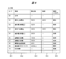
- FIG. 8 shows an example of a code signal that is a configuration example related to a signal issued based on monitoring of a storage battery.
- a code signal illustrated in FIG. 8 is issued as a signal by the monitoring.
- such a code signal may be used in addition to the flag signal described above.
- a code 801, an item 802, a detection value 803, a return 804, and a type 805 are shown in order from the left column.
- the code 801 is indicated by a numerical value such as “01”.
- An item 802 indicates the contents of the code 801, a description of the state, and the like.
- the detection value 803 indicates that the code 801 is generated when the value of the detection value 803 is detected as a condition.
- a return 804 indicates that the return is performed under a condition that satisfies the value of the return 804.
- the type 805 is a value obtained by roughly classifying a plurality of codes into several types, and in this example, there are three types of values corresponding to the above-described flag signal: abnormality, warning, and normal.
- the aforementioned flag signals F1 and F2 indicate a state such as abnormality or warning corresponding to the value of the type of the code.
- the code “00” indicates normality, and no flag such as abnormality or warning is generated.
- the code “01” is “operating upper limit voltage”, which is output when the voltage of the storage battery becomes 500 V or more, and the type is “warning”.
- the code “02” is “overcharge” and is output when the total voltage of the relay panel becomes 520 V or more, and the type is “abnormal”.
- the code “03” is “operating lower limit voltage”, and is output when the voltage of the storage battery becomes 360 V or less, and the type is “warning”.
- the code “04” is “overdischarge”, and is output when the total voltage of the relay panel becomes 300 V or less, and the type is “abnormal”.
- the code “05” is “overcurrent”, and is output when the current of the storage battery exceeds 180 A, and the type is “warning”.
- the code “08” is “storage battery temperature abnormality”, and is output when the temperature of the battery pack 4 reaches 60 ° C. or more, and the type is “abnormal”.
- a code of “09” is “communication disconnection”, and is output when communication between the BCU 31 and the overall BCU 21 is interrupted for two minutes or more, and the type is “abnormal”.
- the code of “10” is “BCU failure”, is output when the BCU 31 is in failure, and the type is “abnormal”.
- the stop time can be shortened by using the mask function described above to bring it into an operating state.
- the maintenance function can be performed in a state where the storage battery group other than the storage battery to be maintained is operated by using the mask function.
- the maintenance staff can use the mask function according to the determination of the status and degree of the failure when the failure of the equipment including the storage battery occurs. Maintenance personnel can easily use the mask function while checking the situation on the screen of the maintenance device.
- the relay board 2 may have the same function as the mask function of the maintenance device 5.
- a button for using the mask function is provided on the operation panel of the relay panel 2.
- the maintenance staff inputs a mask instruction by the function of the relay panel 2.
- the flag signal F2 transmitted from the overall BCU 21 of the relay panel 2 to the power control device 1 is a mask target.
- the flag signal F1 from the BCU 31 of the storage battery panel 3 may be masked.
- a mask signal is transmitted from the maintenance device 5 to the BCU 31 of the storage battery panel 3 via the relay panel 2.
- the BCU 31 of the storage battery panel 3 masks the flag signal F1 from the storage battery panel 3 to the relay panel 2 in accordance with a mask signal, for example, a mask start instruction signal M1.
- a mask signal for example, a mask start instruction signal M1.
- the relay panel 2 detects or determines the detailed state of the storage battery panel 3 using the aforementioned detection signal, flag signal, or code signal.
- the relay panel 2 determines whether or not the mask signal can be applied according to the state of the storage battery panel 3, and executes the mask according to the determination. For example, if the relay panel 2 is a flag indicating a “warning” state or a specific code, the mask can be applied, and if it is a flag indicating an “abnormal” state or a specific code, the mask is applied. Is prohibited.
- the maintenance device 5 provides a setting screen for using this function. The maintenance staff sets on what screen or in what state or signal the mask can be applied. With the above function, conventional control and operation can be performed in a specific state.
- the maintenance device 5 displays not only the normal or abnormal state as the state of the storage battery panel 3 on the screen but also the state of electrical disconnection and connection corresponding to the aforementioned S3, S5, etc. Good.
- the present invention can be used for a power storage system and its maintenance and maintenance work.
Landscapes
- Engineering & Computer Science (AREA)
- Power Engineering (AREA)
- Manufacturing & Machinery (AREA)
- Chemical & Material Sciences (AREA)
- Chemical Kinetics & Catalysis (AREA)
- Electrochemistry (AREA)
- General Chemical & Material Sciences (AREA)
- Microelectronics & Electronic Packaging (AREA)
- Business, Economics & Management (AREA)
- Emergency Management (AREA)
- Charge And Discharge Circuits For Batteries Or The Like (AREA)
- Secondary Cells (AREA)
Abstract
Description
前提である従来例の蓄電システム及びその保全方法の課題や詳細について以下に補足説明する。従来例の蓄電システムは、保全員による蓄電池設備の保全作業時、例えば単一の蓄電池の故障による蓄電池の交換の時、蓄電池の監視の仕組み上、異常または警告等の状態を示す信号が発信される。これにより、従来例の蓄電システムは、該当の蓄電池を含む蓄電池群の単位で、システム即ち充放電機能の稼動を一旦停止させる。これは、蓄電池群の単位で電力を制御する仕組みだからである。それらの複数の蓄電池の電圧やSOC等の状態は、健全性の確保のため、なるべく同じ状態にする必要がある。
図1等に示す本実施の形態の蓄電システムは、蓄電池設備の保守を含む保全の作業時に、蓄電池群の稼動の状態での保全作業を可能とし、蓄電池群の停止時間の短縮を実現する。そのために、本実施の形態の蓄電システムは、図2等に示すように、保全員による保全装置での操作に基づいて蓄電池の監視の信号をマスクするマスク機能を提供する。本実施の形態の蓄電システムの保全方法は、図5,図6に示すように、保全員による保全装置での操作に基づいて上記マスク機能により蓄電システムの蓄電池群を稼動の状態として保全作業を行う手順を含む。
図1は、本実施の形態の蓄電システムの全体の構成を示す。本実施の形態の蓄電システムは、複数の電力制御装置1、複数の中継盤2、複数の蓄電池盤3、及び保全装置5を有する。図1の蓄電システムは、N1個の電力制御装置1であるPCS1~PCSN1と、N2個の中継盤2であるR1~RN2と、N3個の蓄電池盤3であるL1~LN3とを有する。1個の電力制御装置1は、N4個の中継盤2を接続する。例えばN4=3個の場合を示す。N2=N1×N4である。1個の中継盤2は、N5個の蓄電池盤3を接続する。N3=N2×N5である。例えばN5=10個の場合を示す。本実施の形態は、N2個の全中継盤2及びN3個の全蓄電池盤3を、保全作業時のマスク機能が適用可能な対象及び範囲とする。
図2は、図1の蓄電システムの各構成要素の装置の接続及び機能ブロックの構成を示す。電力制御装置1は、制御部11、通信部12、及び電源接続部13を備える。制御部11は、CPUやメモリ等を含み、電力制御装置1の制御処理を行う。通信部12は、中継盤2の統括BCU21の通信部との通信処理を行う。電源接続部13は、中継盤2の並列接続部22の複数の端子を1つにまとめて接続する部分であり、蓄電池電圧を入出力する端子を含む部分である。
図3は、中継盤単位102での複数の蓄電池盤3及び主回路配線の接続の構成を示す。中継盤2である例えばR1に対して、スイッチ、正極の主回路配線301及び負極の主回路配線302を通じて、複数の蓄電池盤3が並列に接続される。1個の電池ブロック40内は、b1~bN6で示すN6個の電池パック4による複数の電池セル(図4)が直列に接続されている。1個の電池パック4は、1個以上の電池セル7を含む。電池セル7は、本実施の形態ではすべてリチウムイオン蓄電池である。なお図3では、蓄電池盤3内の構成は、電池ブロック40のみで簡略的に示す。中継盤2に接続される複数の電池セル7は、図3の構成例では、N6直列及びN5=10並列の接続構成であり、合計では(N5×N6)個である。
図1等において、従来例の蓄電システムにおける蓄電池設備の故障等の不具合、及びそれに対応した異常や警告の状態の発生例は以下である。なお従来例の蓄電システムとして図1と同様の蓄電池設備を持つとする。故障発生例として、図1の例えば蓄電池盤3であるL2のうちの1つの電池パック4、例えば図3の310が故障したとする。L2における310の電池パック4を含む1個の電池ブロック40の保全が必要になったとする。
一方、本実施の形態の蓄電システムは、電池パック4群のPCS単位101等の稼動の状態での保全作業を可能とするために、保全員による保全装置5からの操作に基づいて、マスク機能を利用する。これにより、保全対象の蓄電池盤3を、電池パック4の監視の対象から一時的に外すように、マスクを指示することができる。言い換えると、電池パック4の監視により蓄電池盤3から中継盤2を通じて電力制御装置1へ発信される、異常や警告等の状態を示す信号を、一時的にマスクして無効化することができる。
図4は、中継盤2の統括BCU21、蓄電池盤3のBCU31、及び蓄電池監視部32の構成、並びに、フラグ信号及びマスク信号の構成例を示す。
図5は、実施の形態1の蓄電システム及び保全方法における保全時の第1の処理フローとして、保全員による保守を含む保全作業の例として、蓄電池盤単位103の保守点検の対応を行う場合の処理フローを示す。S1等は処理や作業等のステップを示す。ここでいう保守とは、予めシステム等の停止を計画している場合での保守点検等を指す。
上記総電圧の確認は、電池パック4群における電位差やSOC差が小さいことの確認に対応し、これにより健全性を確保している。
図6は、実施の形態1の蓄電システム及び保全方法における保全時の第2の処理フローとして、保全員による保全作業の例として、蓄電池盤単位103の故障発生時の故障対応を行う場合の処理フローを示す。ここでいう保全とは、システム等の異常等の状態の復旧により正常な状態にすることを指す。図6で、実線枠で示すステップは、図5のステップと概略同様であり、破線枠で示すステップは、図5のステップと異なる部分である。
図7は、保全装置5における保全時のマスク機能の画面例を示す。保全装置5により、マスク機能を含む保全作業の支援のためのインタフェースを提供する。保全員は、保全装置5の画面で、蓄電システムの状態を確認しながら、マスク機能を容易に利用可能である。保全員は、当該マスク機能の画面で、保全対象の蓄電池盤3をマスクする指示をセットする。
図8は、蓄電池の監視に基づいて発行する信号に関する構成例であるコード信号例を示す。従来例の蓄電システムは、当該監視による信号として図8に例示するコード信号が発行されている。本実施の形態の蓄電システムにおいても、前述のフラグ信号だけでなく、このようなコード信号を用いてもよい。
以上説明したように、本実施の形態の蓄電システム及び保全方法によれば、蓄電池設備の保全作業時における蓄電池群の単位での稼動の停止の時間を短縮してシステム全体の稼働率を上げることができる。これにより、利用者にとっての利便性を高くできる。本実施の形態は、蓄電池の監視に基づく蓄電池群の停止の時間に関して、マスク機能を利用することで、保全対象の蓄電池以外の蓄電池群を稼動させた状態で保全作業が可能である。特に、多数のリチウムイオン二次電池及びその監視の機能を備える、常用が想定される大規模蓄電システムに関して、蓄電池群の稼動の状態での保全作業が可能である。保全員は、蓄電池を含む設備の不具合が発生した場合、不具合の状況や程度の判断に応じて、マスク機能を利用できる。保全員は、保全装置の画面で、状況を確認しながら、容易にマスク機能を利用できる。
Claims (8)
- 1つ以上の電力制御装置に接続される1つ以上の中継盤と、
前記中継盤に接続され、1つ以上の蓄電池が搭載される複数の蓄電池盤と、
保全員による保守を含む保全の作業時に前記中継盤に接続される1つ以上の保全装置と、を備え、
前記蓄電池盤は、前記蓄電池の状態の監視に基づいて当該状態を検知または判定した第1の信号を上位の前記中継盤へ発信し、
前記中継盤は、前記第1の信号に基づいた第2の信号を上位の前記電力制御装置へ発信し、
前記保全装置は、前記保全員による保全対象の蓄電池盤を指定する操作に基づいて、前記保全対象の蓄電池盤の上位の前記中継盤へ、第3の信号を送信し、
前記中継盤は、前記第3の信号に従い、前記保全対象の蓄電池盤からの第1の信号、または当該第1の信号に基づいた第2の信号を、マスクして無効化する、蓄電システム。 - 請求項1記載の蓄電システムにおいて、
前記蓄電池盤は、
前記蓄電池の電圧、電流、及び温度を含む状態の監視に基づいて当該状態を検知または判定した信号を発信する監視部と、
前記監視部による信号に基づいて前記蓄電池の状態を検知または判定した前記第1の信号を上位の前記中継盤へ発信する第1の蓄電池制御部と、を含み、
前記中継盤は、前記第1の信号に基づいて前記複数の蓄電池盤の状態を検知または判定した前記第2の信号を上位の前記電力制御装置へ発信する第2の蓄電池制御部を含み、
前記保全装置は、前記中継盤の第2の蓄電池制御部へ前記第3の信号を送信し、
前記中継盤の第2の蓄電池制御部は、前記第3の信号に従い、前記第1の信号または第2の信号を、マスクして無効化する、蓄電システム。 - 請求項1記載の蓄電システムにおいて、
前記保全装置は、前記保全員による前記保全対象の蓄電池盤に関する前記マスクの開始の指示に基づいて、前記第3の信号としてマスク開始指示信号を送信し、
前記中継盤は、前記マスク開始指示信号に従い、前記第1の信号または第2の信号を、マスクして無効化し、
前記保全装置は、前記保全員による前記保全対象の蓄電池盤に関する前記マスクの状態の解除の指示に基づいて、前記第3の信号としてマスク解除指示信号を送信し、
前記中継盤は、前記マスク解除指示信号に従い、前記第1の信号または第2の信号のマスクの状態を解除して有効化する、蓄電システム。 - 請求項3記載の蓄電システムにおいて、
前記保全装置は、前記保全員による前記マスクの操作のための画面を提供し、
前記画面は、前記複数の蓄電池盤の識別情報及び状態を表示する項目と、前記複数の蓄電池盤のうち前記マスクの対象を選択する項目と、前記マスクの開始を指示する項目と、前記マスクの解除を指示する項目と、を含み、
前記保全装置は、前記画面での前記マスクの対象の選択及び前記マスクの開始の指示に応じて、前記マスク開始指示信号を送信し、前記マスクの解除の指示に応じて、前記マスク解除指示信号を送信する、蓄電システム。 - 請求項1記載の蓄電システムにおいて、
前記第1の信号または第2の信号は、正常、異常、または警告の状態を示す信号を含み、
前記マスクの適用可能な対象は、前記異常または警告の状態を示す信号である、蓄電システム。 - 請求項1記載の蓄電システムにおいて、
前記第1の信号または第2の信号は、過電圧、過電流、過充電、過放電、過温度、または通信断のうち少なくとも1つの状態を示すコード信号を含み、
前記マスクの適用可能な対象は、前記コード信号のうち特定の状態を示すコード信号である、蓄電システム。 - 1つ以上の電力制御装置に接続される1つ以上の中継盤と、前記中継盤に接続され、1つ以上の蓄電池が搭載される複数の蓄電池盤と、保全員による保守を含む保全の作業時に前記中継盤に接続される1つ以上の保全装置と、を備える蓄電システムの保守を含む保全方法であって、
前記保全員の操作に基づいて、前記保全装置により、保全対象の蓄電池盤の上位の中継盤へ、マスク開始指示信号を送信し、前記中継盤により、前記マスク開始指示信号に従い、前記保全対象の蓄電池盤から上位の中継盤へ発信される第1の信号、または当該第1の信号に基づいて当該中継盤から上位の電力制御装置へ発信される第2の信号を、マスクして無効化する第1の手順と、
前記保全員の操作に基づいて、前記保全対象の蓄電池盤が電気的に切り離された状態で、当該保全対象の蓄電池盤に関する保全の作業が行われ、当該保全後の蓄電池盤が電気的に接続される第2の手順と、
前記保全員の操作に基づいて、前記保全装置により、前記保全対象の蓄電池盤の上位の中継盤へ、マスク解除指示信号を送信し、前記中継盤により、前記マスク解除指示信号に従い、前記第1の信号または第2の信号のマスクの状態を解除して有効化する第3の手順と、
を有する、蓄電システムの保全方法。 - 1つ以上の電力制御装置に接続される1つ以上の中継盤と、前記中継盤に接続され、1つ以上の蓄電池が搭載される複数の蓄電池盤と、保全員による保守を含む保全の作業時に前記中継盤に接続される1つ以上の保全装置と、を備える蓄電システムの保守を含む保全方法であって、
前記蓄電池盤により、前記蓄電池の状態の監視に基づいて当該状態を検知または判定した第1の信号を上位の前記中継盤へ発信する第1の手順と、
前記中継盤により、前記第1の信号に基づいた第2の信号を上位の前記電力制御装置へ発信する第2の手順と、
前記電力制御装置により、前記第2の信号に基づいて下位の前記中継盤及び当該中継盤に接続される複数の蓄電池盤を含む単位での稼動を停止させる第3の手順と、
前記保全員の操作に基づいて、前記保全装置により、保全対象の蓄電池盤の上位の中継盤へ、マスク開始指示信号を送信し、前記中継盤により、前記マスク開始指示信号に従い、前記保全対象の蓄電池盤から上位の中継盤へ発信される第1の信号、または当該第1の信号に基づいて当該中継盤から上位の電力制御装置へ発信される第2の信号を、マスクして無効化する第4の手順と、
前記保全員の操作に基づいて、前記保全対象の蓄電池盤が電気的に切り離された状態で、前記電力制御装置により前記下位の中継盤及び複数の蓄電池盤を含む単位での稼動が再開される第5の手順と、
前記保全員の操作に基づいて、前記保全対象の蓄電池盤に関する保全の作業が行われ、当該保全後の蓄電池盤が電気的に接続される第6の手順と、
前記保全員の操作に基づいて、前記保全装置により、前記保全対象の蓄電池盤の上位の中継盤へ、マスク解除指示信号を送信し、前記中継盤により、前記マスク解除指示信号に従い、前記第1の信号または第2の信号のマスクの状態を解除して有効化する第7の手順と、
を有する、蓄電システムの保全方法。
Priority Applications (3)
| Application Number | Priority Date | Filing Date | Title |
|---|---|---|---|
| US15/023,154 US20160233560A1 (en) | 2013-09-20 | 2014-09-17 | Power Storage System and Maintenance Method of the Power Storage System |
| EP14846418.3A EP3048663B1 (en) | 2013-09-20 | 2014-09-17 | Power storage system and method of maintaining power storage system |
| JP2015537942A JP6135767B2 (ja) | 2013-09-20 | 2014-09-17 | 蓄電システム及び蓄電システムの保全方法 |
Applications Claiming Priority (2)
| Application Number | Priority Date | Filing Date | Title |
|---|---|---|---|
| JP2013196201 | 2013-09-20 | ||
| JP2013-196201 | 2013-09-20 |
Publications (1)
| Publication Number | Publication Date |
|---|---|
| WO2015041249A1 true WO2015041249A1 (ja) | 2015-03-26 |
Family
ID=52688896
Family Applications (1)
| Application Number | Title | Priority Date | Filing Date |
|---|---|---|---|
| PCT/JP2014/074557 Ceased WO2015041249A1 (ja) | 2013-09-20 | 2014-09-17 | 蓄電システム及び蓄電システムの保全方法 |
Country Status (4)
| Country | Link |
|---|---|
| US (1) | US20160233560A1 (ja) |
| EP (1) | EP3048663B1 (ja) |
| JP (1) | JP6135767B2 (ja) |
| WO (1) | WO2015041249A1 (ja) |
Cited By (5)
| Publication number | Priority date | Publication date | Assignee | Title |
|---|---|---|---|---|
| EP3176856A1 (en) * | 2015-12-04 | 2017-06-07 | Kabushiki Kaisha Toshiba | Storage battery system, storage battery unit, and computer program product |
| CN107925241A (zh) * | 2015-08-14 | 2018-04-17 | 光城公司 | 用于能量生成系统中的逆变器电力控制系统的多个能量存储设备 |
| US11309714B2 (en) | 2016-11-02 | 2022-04-19 | Tesla, Inc. | Micro-batteries for energy generation systems |
| WO2023176104A1 (ja) * | 2022-03-16 | 2023-09-21 | パナソニックIpマネジメント株式会社 | 電源システム、電動移動体、充電器、及び通電確認方法 |
| WO2025177831A1 (ja) * | 2024-02-19 | 2025-08-28 | パナソニックIpマネジメント株式会社 | 情報処理方法、情報処理装置、及び情報処理プログラム |
Families Citing this family (9)
| Publication number | Priority date | Publication date | Assignee | Title |
|---|---|---|---|---|
| CN107409452B (zh) * | 2015-03-17 | 2020-03-10 | 飞利浦照明控股有限公司 | 具有至少四个不同状态的驱动器 |
| JP6807555B2 (ja) * | 2015-03-23 | 2021-01-06 | パナソニックIpマネジメント株式会社 | 蓄電池収納装置の制御方法、プログラム、蓄電池収納装置および情報端末の制御方法 |
| JP6831281B2 (ja) * | 2017-03-27 | 2021-02-17 | 株式会社デンソーテン | 電池監視システムおよび電池監視装置 |
| US12523704B2 (en) | 2019-02-26 | 2026-01-13 | Gs Yuasa International Ltd. | Lead-acid battery monitoring apparatus and lead-acid battery monitoring method |
| JP6708318B1 (ja) | 2019-02-27 | 2020-06-10 | 株式会社Gsユアサ | 蓄電池監視装置及び蓄電池監視方法 |
| JP7244635B2 (ja) | 2020-03-27 | 2023-03-22 | 東莞新能安科技有限公司 | 並列接続電池セットの充放電管理方法、電子装置及び電気システム |
| CN111431228B (zh) * | 2020-03-27 | 2023-06-20 | 东莞新能安科技有限公司 | 并联电池组充放电管理方法及电子装置 |
| JP7562991B2 (ja) | 2020-05-26 | 2024-10-08 | 株式会社Gsユアサ | 蓄電池監視装置及び蓄電池監視装置の保守方法 |
| WO2021241252A1 (ja) | 2020-05-29 | 2021-12-02 | 株式会社Gsユアサ | 鉛蓄電池監視装置及び鉛蓄電池監視方法 |
Citations (6)
| Publication number | Priority date | Publication date | Assignee | Title |
|---|---|---|---|---|
| JPH06283210A (ja) * | 1993-01-29 | 1994-10-07 | Canon Inc | 蓄電装置及び電力システム |
| JP2012244843A (ja) | 2011-05-23 | 2012-12-10 | Hitachi Ltd | 電池システム |
| JP2012253862A (ja) * | 2011-06-01 | 2012-12-20 | Hitachi Ltd | 蓄電システム |
| JP2013031237A (ja) * | 2011-07-25 | 2013-02-07 | Joy Ride Technology Co Ltd | 電池装置及び電力供給システム |
| JP2013038831A (ja) * | 2011-08-03 | 2013-02-21 | Denso Corp | 電池制御装置 |
| JP2013127893A (ja) * | 2011-12-19 | 2013-06-27 | Toshiba Corp | 蓄電装置及びその保守方法 |
Family Cites Families (3)
| Publication number | Priority date | Publication date | Assignee | Title |
|---|---|---|---|---|
| US6469512B2 (en) * | 2000-01-12 | 2002-10-22 | Honeywell International Inc. | System and method for determining battery state-of-health |
| EP2658027A4 (en) * | 2011-03-14 | 2014-04-09 | Sanyo Electric Co | POWER SYSTEM |
| WO2012133274A1 (ja) * | 2011-03-30 | 2012-10-04 | 三洋電機株式会社 | 蓄電システム及び移動体 |
-
2014
- 2014-09-17 WO PCT/JP2014/074557 patent/WO2015041249A1/ja not_active Ceased
- 2014-09-17 EP EP14846418.3A patent/EP3048663B1/en active Active
- 2014-09-17 US US15/023,154 patent/US20160233560A1/en not_active Abandoned
- 2014-09-17 JP JP2015537942A patent/JP6135767B2/ja not_active Expired - Fee Related
Patent Citations (6)
| Publication number | Priority date | Publication date | Assignee | Title |
|---|---|---|---|---|
| JPH06283210A (ja) * | 1993-01-29 | 1994-10-07 | Canon Inc | 蓄電装置及び電力システム |
| JP2012244843A (ja) | 2011-05-23 | 2012-12-10 | Hitachi Ltd | 電池システム |
| JP2012253862A (ja) * | 2011-06-01 | 2012-12-20 | Hitachi Ltd | 蓄電システム |
| JP2013031237A (ja) * | 2011-07-25 | 2013-02-07 | Joy Ride Technology Co Ltd | 電池装置及び電力供給システム |
| JP2013038831A (ja) * | 2011-08-03 | 2013-02-21 | Denso Corp | 電池制御装置 |
| JP2013127893A (ja) * | 2011-12-19 | 2013-06-27 | Toshiba Corp | 蓄電装置及びその保守方法 |
Non-Patent Citations (1)
| Title |
|---|
| See also references of EP3048663A4 |
Cited By (7)
| Publication number | Priority date | Publication date | Assignee | Title |
|---|---|---|---|---|
| CN107925241A (zh) * | 2015-08-14 | 2018-04-17 | 光城公司 | 用于能量生成系统中的逆变器电力控制系统的多个能量存储设备 |
| EP3360221A1 (en) * | 2015-08-14 | 2018-08-15 | SolarCity Corporation | Multiple energy storage devices for inverter power control systems in an energy generation system |
| US10644510B2 (en) | 2015-08-14 | 2020-05-05 | Solarcity Corporation | Multiple energy storage devices for inverter power control systems in an energy generation system |
| EP3176856A1 (en) * | 2015-12-04 | 2017-06-07 | Kabushiki Kaisha Toshiba | Storage battery system, storage battery unit, and computer program product |
| US11309714B2 (en) | 2016-11-02 | 2022-04-19 | Tesla, Inc. | Micro-batteries for energy generation systems |
| WO2023176104A1 (ja) * | 2022-03-16 | 2023-09-21 | パナソニックIpマネジメント株式会社 | 電源システム、電動移動体、充電器、及び通電確認方法 |
| WO2025177831A1 (ja) * | 2024-02-19 | 2025-08-28 | パナソニックIpマネジメント株式会社 | 情報処理方法、情報処理装置、及び情報処理プログラム |
Also Published As
| Publication number | Publication date |
|---|---|
| JP6135767B2 (ja) | 2017-05-31 |
| EP3048663A4 (en) | 2017-06-21 |
| JPWO2015041249A1 (ja) | 2017-03-02 |
| EP3048663A1 (en) | 2016-07-27 |
| EP3048663B1 (en) | 2019-12-18 |
| US20160233560A1 (en) | 2016-08-11 |
Similar Documents
| Publication | Publication Date | Title |
|---|---|---|
| JP6135767B2 (ja) | 蓄電システム及び蓄電システムの保全方法 | |
| JP5166379B2 (ja) | 電力連携システム | |
| JP6402925B2 (ja) | 蓄電池搭載機器及びその保守運用システム | |
| JP6184111B2 (ja) | 蓄電池システムとその運用方法 | |
| CN104300669B (zh) | 核电站直流电源混合供电系统 | |
| US9847657B2 (en) | Battery system | |
| JP5361298B2 (ja) | 電池パック | |
| CN107086613A (zh) | 一种分布式多子系统组成的n+m冗余ups系统 | |
| CN103595117B (zh) | 一种井下ups电源管理监测系统 | |
| JP5361594B2 (ja) | リチウムイオン二次電池システムおよび管理装置への電力供給方法 | |
| JP6756015B1 (ja) | 電源盤及び電源設備 | |
| JP2010130738A (ja) | 二次電池パック | |
| CN101834467B (zh) | 一种智能共用电池组ups系统及其控制方法 | |
| US20150339915A1 (en) | Advanced interconnected smoke alarm system with centrally located battery and dc power supply | |
| CN205610335U (zh) | 具有提醒功能的不间断电源系统 | |
| US20120117408A1 (en) | Switching device, a switching device control method and a switching device control program | |
| CN204694790U (zh) | 一种适用于核电厂ups系统的霍尔传感器故障监测装置 | |
| CN106972623A (zh) | 一种交流电供电装置 | |
| JP5897941B2 (ja) | 2次電池の充放電検査装置 | |
| CN107086614B (zh) | 一种集中监控的多子系统组成的n+m冗余ups系统 | |
| JP5858236B2 (ja) | 蓄電池システム | |
| CN109064699A (zh) | 蓄电池电气火灾监控系统 | |
| JP5448564B2 (ja) | リチウムイオン組電池の管理装置および管理方法 | |
| CN113193646A (zh) | 供电装置、方法及系统 | |
| JP2011160639A (ja) | 瞬低対策装置 |
Legal Events
| Date | Code | Title | Description |
|---|---|---|---|
| 121 | Ep: the epo has been informed by wipo that ep was designated in this application |
Ref document number: 14846418 Country of ref document: EP Kind code of ref document: A1 |
|
| ENP | Entry into the national phase |
Ref document number: 2015537942 Country of ref document: JP Kind code of ref document: A |
|
| REEP | Request for entry into the european phase |
Ref document number: 2014846418 Country of ref document: EP |
|
| WWE | Wipo information: entry into national phase |
Ref document number: 15023154 Country of ref document: US Ref document number: 2014846418 Country of ref document: EP |
|
| NENP | Non-entry into the national phase |
Ref country code: DE |