WO2015045224A1 - レーダ装置及び物体検出方法 - Google Patents
レーダ装置及び物体検出方法 Download PDFInfo
- Publication number
- WO2015045224A1 WO2015045224A1 PCT/JP2014/003314 JP2014003314W WO2015045224A1 WO 2015045224 A1 WO2015045224 A1 WO 2015045224A1 JP 2014003314 W JP2014003314 W JP 2014003314W WO 2015045224 A1 WO2015045224 A1 WO 2015045224A1
- Authority
- WO
- WIPO (PCT)
- Prior art keywords
- unit
- determination threshold
- radar
- value
- amplitude
- Prior art date
- Legal status (The legal status is an assumption and is not a legal conclusion. Google has not performed a legal analysis and makes no representation as to the accuracy of the status listed.)
- Ceased
Links
Images


Classifications
-
- G—PHYSICS
- G01—MEASURING; TESTING
- G01S—RADIO DIRECTION-FINDING; RADIO NAVIGATION; DETERMINING DISTANCE OR VELOCITY BY USE OF RADIO WAVES; LOCATING OR PRESENCE-DETECTING BY USE OF THE REFLECTION OR RERADIATION OF RADIO WAVES; ANALOGOUS ARRANGEMENTS USING OTHER WAVES
- G01S13/00—Systems using the reflection or reradiation of radio waves, e.g. radar systems; Analogous systems using reflection or reradiation of waves whose nature or wavelength is irrelevant or unspecified
- G01S13/02—Systems using reflection of radio waves, e.g. primary radar systems; Analogous systems
- G01S13/04—Systems determining presence of a target
-
- G—PHYSICS
- G01—MEASURING; TESTING
- G01S—RADIO DIRECTION-FINDING; RADIO NAVIGATION; DETERMINING DISTANCE OR VELOCITY BY USE OF RADIO WAVES; LOCATING OR PRESENCE-DETECTING BY USE OF THE REFLECTION OR RERADIATION OF RADIO WAVES; ANALOGOUS ARRANGEMENTS USING OTHER WAVES
- G01S7/00—Details of systems according to groups G01S13/00, G01S15/00, G01S17/00
- G01S7/02—Details of systems according to groups G01S13/00, G01S15/00, G01S17/00 of systems according to group G01S13/00
- G01S7/28—Details of pulse systems
- G01S7/285—Receivers
- G01S7/288—Coherent receivers
- G01S7/2886—Coherent receivers using I/Q processing
-
- G—PHYSICS
- G01—MEASURING; TESTING
- G01S—RADIO DIRECTION-FINDING; RADIO NAVIGATION; DETERMINING DISTANCE OR VELOCITY BY USE OF RADIO WAVES; LOCATING OR PRESENCE-DETECTING BY USE OF THE REFLECTION OR RERADIATION OF RADIO WAVES; ANALOGOUS ARRANGEMENTS USING OTHER WAVES
- G01S13/00—Systems using the reflection or reradiation of radio waves, e.g. radar systems; Analogous systems using reflection or reradiation of waves whose nature or wavelength is irrelevant or unspecified
- G01S13/02—Systems using reflection of radio waves, e.g. primary radar systems; Analogous systems
- G01S13/06—Systems determining position data of a target
- G01S13/08—Systems for measuring distance only
- G01S13/10—Systems for measuring distance only using transmission of interrupted, pulse modulated waves
- G01S13/18—Systems for measuring distance only using transmission of interrupted, pulse modulated waves wherein range gates are used
-
- G—PHYSICS
- G01—MEASURING; TESTING
- G01S—RADIO DIRECTION-FINDING; RADIO NAVIGATION; DETERMINING DISTANCE OR VELOCITY BY USE OF RADIO WAVES; LOCATING OR PRESENCE-DETECTING BY USE OF THE REFLECTION OR RERADIATION OF RADIO WAVES; ANALOGOUS ARRANGEMENTS USING OTHER WAVES
- G01S13/00—Systems using the reflection or reradiation of radio waves, e.g. radar systems; Analogous systems using reflection or reradiation of waves whose nature or wavelength is irrelevant or unspecified
- G01S13/02—Systems using reflection of radio waves, e.g. primary radar systems; Analogous systems
- G01S13/06—Systems determining position data of a target
- G01S13/08—Systems for measuring distance only
- G01S13/10—Systems for measuring distance only using transmission of interrupted, pulse modulated waves
- G01S13/26—Systems for measuring distance only using transmission of interrupted, pulse modulated waves wherein the transmitted pulses use a frequency- or phase-modulated carrier wave
-
- G—PHYSICS
- G01—MEASURING; TESTING
- G01S—RADIO DIRECTION-FINDING; RADIO NAVIGATION; DETERMINING DISTANCE OR VELOCITY BY USE OF RADIO WAVES; LOCATING OR PRESENCE-DETECTING BY USE OF THE REFLECTION OR RERADIATION OF RADIO WAVES; ANALOGOUS ARRANGEMENTS USING OTHER WAVES
- G01S13/00—Systems using the reflection or reradiation of radio waves, e.g. radar systems; Analogous systems using reflection or reradiation of waves whose nature or wavelength is irrelevant or unspecified
- G01S13/02—Systems using reflection of radio waves, e.g. primary radar systems; Analogous systems
- G01S13/06—Systems determining position data of a target
- G01S13/42—Simultaneous measurement of distance and other co-ordinates
-
- G—PHYSICS
- G01—MEASURING; TESTING
- G01S—RADIO DIRECTION-FINDING; RADIO NAVIGATION; DETERMINING DISTANCE OR VELOCITY BY USE OF RADIO WAVES; LOCATING OR PRESENCE-DETECTING BY USE OF THE REFLECTION OR RERADIATION OF RADIO WAVES; ANALOGOUS ARRANGEMENTS USING OTHER WAVES
- G01S13/00—Systems using the reflection or reradiation of radio waves, e.g. radar systems; Analogous systems using reflection or reradiation of waves whose nature or wavelength is irrelevant or unspecified
- G01S13/02—Systems using reflection of radio waves, e.g. primary radar systems; Analogous systems
- G01S13/50—Systems of measurement based on relative movement of target
- G01S13/52—Discriminating between fixed and moving objects or between objects moving at different speeds
- G01S13/56—Discriminating between fixed and moving objects or between objects moving at different speeds for presence detection
-
- G—PHYSICS
- G01—MEASURING; TESTING
- G01S—RADIO DIRECTION-FINDING; RADIO NAVIGATION; DETERMINING DISTANCE OR VELOCITY BY USE OF RADIO WAVES; LOCATING OR PRESENCE-DETECTING BY USE OF THE REFLECTION OR RERADIATION OF RADIO WAVES; ANALOGOUS ARRANGEMENTS USING OTHER WAVES
- G01S13/00—Systems using the reflection or reradiation of radio waves, e.g. radar systems; Analogous systems using reflection or reradiation of waves whose nature or wavelength is irrelevant or unspecified
- G01S13/02—Systems using reflection of radio waves, e.g. primary radar systems; Analogous systems
- G01S13/50—Systems of measurement based on relative movement of target
- G01S13/58—Velocity or trajectory determination systems; Sense-of-movement determination systems
- G01S13/581—Velocity or trajectory determination systems; Sense-of-movement determination systems using transmission of interrupted pulse modulated waves and based upon the Doppler effect resulting from movement of targets
- G01S13/582—Velocity or trajectory determination systems; Sense-of-movement determination systems using transmission of interrupted pulse modulated waves and based upon the Doppler effect resulting from movement of targets adapted for simultaneous range and velocity measurements
-
- G—PHYSICS
- G01—MEASURING; TESTING
- G01S—RADIO DIRECTION-FINDING; RADIO NAVIGATION; DETERMINING DISTANCE OR VELOCITY BY USE OF RADIO WAVES; LOCATING OR PRESENCE-DETECTING BY USE OF THE REFLECTION OR RERADIATION OF RADIO WAVES; ANALOGOUS ARRANGEMENTS USING OTHER WAVES
- G01S13/00—Systems using the reflection or reradiation of radio waves, e.g. radar systems; Analogous systems using reflection or reradiation of waves whose nature or wavelength is irrelevant or unspecified
- G01S13/66—Radar-tracking systems; Analogous systems
- G01S13/72—Radar-tracking systems; Analogous systems for two-dimensional [2D] tracking, e.g. combination of angle and range tracking, track-while-scan radar
- G01S13/723—Radar-tracking systems; Analogous systems for two-dimensional [2D] tracking, e.g. combination of angle and range tracking, track-while-scan radar by using numerical data
-
- G—PHYSICS
- G01—MEASURING; TESTING
- G01S—RADIO DIRECTION-FINDING; RADIO NAVIGATION; DETERMINING DISTANCE OR VELOCITY BY USE OF RADIO WAVES; LOCATING OR PRESENCE-DETECTING BY USE OF THE REFLECTION OR RERADIATION OF RADIO WAVES; ANALOGOUS ARRANGEMENTS USING OTHER WAVES
- G01S7/00—Details of systems according to groups G01S13/00, G01S15/00, G01S17/00
- G01S7/02—Details of systems according to groups G01S13/00, G01S15/00, G01S17/00 of systems according to group G01S13/00
- G01S7/28—Details of pulse systems
- G01S7/285—Receivers
- G01S7/288—Coherent receivers
-
- G—PHYSICS
- G01—MEASURING; TESTING
- G01S—RADIO DIRECTION-FINDING; RADIO NAVIGATION; DETERMINING DISTANCE OR VELOCITY BY USE OF RADIO WAVES; LOCATING OR PRESENCE-DETECTING BY USE OF THE REFLECTION OR RERADIATION OF RADIO WAVES; ANALOGOUS ARRANGEMENTS USING OTHER WAVES
- G01S13/00—Systems using the reflection or reradiation of radio waves, e.g. radar systems; Analogous systems using reflection or reradiation of waves whose nature or wavelength is irrelevant or unspecified
- G01S13/02—Systems using reflection of radio waves, e.g. primary radar systems; Analogous systems
- G01S13/50—Systems of measurement based on relative movement of target
- G01S13/58—Velocity or trajectory determination systems; Sense-of-movement determination systems
- G01S13/589—Velocity or trajectory determination systems; Sense-of-movement determination systems measuring the velocity vector
-
- G—PHYSICS
- G01—MEASURING; TESTING
- G01S—RADIO DIRECTION-FINDING; RADIO NAVIGATION; DETERMINING DISTANCE OR VELOCITY BY USE OF RADIO WAVES; LOCATING OR PRESENCE-DETECTING BY USE OF THE REFLECTION OR RERADIATION OF RADIO WAVES; ANALOGOUS ARRANGEMENTS USING OTHER WAVES
- G01S13/00—Systems using the reflection or reradiation of radio waves, e.g. radar systems; Analogous systems using reflection or reradiation of waves whose nature or wavelength is irrelevant or unspecified
- G01S13/02—Systems using reflection of radio waves, e.g. primary radar systems; Analogous systems
- G01S13/50—Systems of measurement based on relative movement of target
- G01S13/58—Velocity or trajectory determination systems; Sense-of-movement determination systems
- G01S13/62—Sense-of-movement determination
Definitions
- the present disclosure relates to a radar apparatus and an object detection method for detecting an object as a target.
- Patent Document 1 an object detection device disclosed in Patent Document 1 is known as a prior art related to a target (object) detection method using a radar device.
- the object detection apparatus shown in Patent Document 1 receives a reflected wave, which is a radar pulse transmitted from a transmission antenna and reflected by a target (for example, an object present in a radar pulse detection region), by a reception antenna.
- the object detection device detects a moving object (for example, a pedestrian or a vehicle) by analyzing a reflected wave (received signal) received during the first time.
- the object detection apparatus uses the second time longer than the first time for analysis of the received reflected wave (reception signal), that is, uses a larger number of data to detect the moving object.
- a minute moving object for example, a gentle movement of a person sitting or standing
- Patent Document 1 since the measurement time required for the detection process of the moving object is longer than the measurement time of the detection process of the moving object, the time required for one detection process of the moving object and the detection process of the minute object is performed. It is difficult to measure in a short time.
- the present disclosure provides a radar apparatus and an object detection method for detecting an object in a shorter measurement period by suppressing deterioration in detection accuracy of an object in order to solve the above-described conventional problems.
- a radar transmitter that transmits a radar transmission signal that is a high-frequency repetitive waveform from a transmission antenna, and a signal that includes a repetitive waveform of a reflected wave signal in which the radar transmission signal is reflected by an object are received by a receiving antenna;
- An antenna system processing unit that samples the signal including the repetitive waveform of the reflected wave signal at a predetermined discrete time, and (Tp + 1) (Tp is a sample of the signal including the repetitive waveform of the reflected wave signal).
- an object detection processing unit that detects the presence / absence of a desired object using an amplitude difference at each of (integer) sampling points.
- the present disclosure is an object detection method in a radar apparatus, the step of transmitting a radar transmission signal that is a high-frequency repetitive waveform from a transmission antenna, and the repetitive waveform of a reflected wave signal in which the radar transmission signal is reflected by an object
- a radar transmission signal that is a high-frequency repetitive waveform from a transmission antenna
- a signal including a repetitive waveform of the reflected wave signal a step of sampling the signal including a repetitive waveform of the reflected wave signal at a predetermined discrete time, and a signal including a repetitive waveform of the reflected wave signal Detecting the presence / absence of a desired object using the amplitude difference at each of the sampled (Tp + 1) sampling points (Tp is an integer).
- the block diagram which shows simply the internal structure of the radar apparatus of 1st Embodiment The block diagram which shows simply the internal structure of the radar apparatus which a radar transmission part transmits the radar transmission signal by which frequency modulation was carried out in 1st Embodiment.
- the block diagram which shows the internal structure of the radar receiving part of the radar apparatus of 1st Embodiment in detail A graph showing the relationship between the time series output number of the periodic addition value CI and the amplitude of the periodic addition value CI
- B calculation of the maximum value A max (k, Cu) of the absolute value of the amplitude difference.
- the graph which shows the relationship between the electric power value of measurement addition value CI (k, Co), and the appearance frequency from which an electric power value is obtained In the case where there is no case and persons person is present, the graph showing the relationship between the frequency where the maximum value A max of the absolute value of the maximum value A max and the amplitude difference between the absolute value of the amplitude difference is obtained.
- the block diagram which shows simply the internal structure of the radar apparatus of 2nd Embodiment In the second embodiment, a block diagram simply showing the internal configuration of a radar apparatus in which a radar transmitter transmits a frequency-modulated radar transmission signal The block diagram which shows the internal structure of the radar receiving part of the radar apparatus of 2nd Embodiment in detail A graph showing an example of an addition value CI on the IQ plane when a person exists
- the block diagram which shows the internal structure of the radar receiving part of the radar apparatus of 3rd Embodiment in detail Block diagram showing in detail the internal configuration of the complex average distance orientation profile generator The flowchart explaining the operation
- A A graph showing an example of a measurement result of a person in a conventional radar apparatus, (B) a person is extracted by using a complex average, but the second determination threshold HM_bg (k, k, in the radar apparatus of the third embodiment) (c) a graph showing an example of a person measurement result when not using (cc), (C) an example of a person measurement result when using the second determination threshold HM_bg (k, cc) in the radar apparatus of the third embodiment Graph showing The block diagram which shows the internal structure of the radar receiving part of the radar apparatus of 4th Embodiment in detail The flowchart explaining the operation
- the block diagram which shows the internal structure of the radar receiving part of the radar apparatus of 5th Embodiment in detail
- Patent Document 1 in the detection process of a minute animal body, a measurement time that is at least twice as long as the assumed period of movement of the minute animal body is required.
- the object detection apparatus shown in Patent Document 1 uses a constant value as a determination threshold for detecting an object regardless of the environment in which the object to be detected exists, in the detection process of the moving object and the moving object. Yes. For this reason, depending on the surrounding environment where the object exists, the detection accuracy may be deteriorated when a constant threshold value is uniformly used.
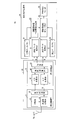
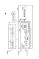
- FIG. 1 is a block diagram schematically showing the internal configuration of the radar apparatus 1 according to the first embodiment.
- FIG. 2 is a block diagram simply showing an internal configuration of the radar apparatus 1F that transmits a radar transmission signal whose frequency is modulated by the radar transmitter TxF in the first embodiment.
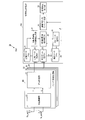
- FIG. 3 is a block diagram illustrating in detail the internal configuration of the radar receiver Rx of the radar apparatus 1 according to the first embodiment.
- the radar apparatus 1 shown in FIG. 1 transmits a high-frequency radar transmission signal generated by the radar transmitter Tx from the transmission antenna Tx_ant1.
- the radar apparatus 1 receives a reflected wave signal, which is a radar transmission signal reflected by an object (not shown) as a target, by a receiving antenna Rx_ant1.
- the radar apparatus 1 detects the presence / absence of the target object and the position of the object by performing signal processing on the reflected wave signal received by the receiving antenna.
- the target object is a target to be detected by the radar apparatus 1 and includes, for example, a person or a vehicle, and the same applies to the following embodiments.
- the radar apparatus 1 shown in FIG. 1 includes a reference signal generation unit Lo, a radar transmission unit Tx, and a radar reception unit Rx.
- the reference signal generator Lo is connected to the radar transmitter Tx and the radar receiver Rx.
- the reference signal generation unit Lo commonly supplies a reference signal as a reference signal to the radar transmission unit Tx and the radar reception unit Rx, and synchronizes the processing of the radar transmission unit Tx and the radar reception unit Rx.
- the radar transmission unit Tx includes a transmission signal generation unit 2 and a transmission radio (RF) unit 3 to which a transmission antenna Tx_ant1 is connected.
- RF transmission radio
- the transmission signal generation unit 2 generates a transmission reference clock signal obtained by multiplying the reference signal by a predetermined factor based on the reference signal generated by the reference signal generation unit Lo.
- the transmission signal generator 2 operates based on the transmission reference clock signal.
- Baseband transmission signal by the transmission signal generating unit 2 generates, for example, the transmission interval Tw transmission period Tr of the radar transmission signal, No [number of one code per transmitted reference clock signal of the code sequence C n in the code length L ] Is used for the modulation.
- n is 1 to L (> 0).
- L (integer) represents the code length of the code sequence C n.
- the transmission signal generation unit 2 modulates using Nu [numbers] samples in the non-signal section (Tr-Tw) [seconds] of the transmission cycle Tr.
- the transmission signal generation unit 2 periodically generates a baseband transmission signal r (k, M) represented by Equation (1) by modulation of a code sequence C n having a code length L.
- the transmission signal r (k, M) represents a transmission signal at the discrete time k in the Mth transmission cycle Tr, and is an orthogonal signal component Q obtained by multiplying the in-phase signal component I (k, M) by the imaginary unit j. The result of addition with (k, M) is obtained (see Equation (1)).
- the transmission radio unit 3 generates a transmission reference signal in a carrier frequency band obtained by multiplying the reference signal by a predetermined multiple on the basis of the reference signal generated by the reference signal generation unit Lo.
- the multiplied signal may be a signal multiplied by different multiples for the transmission signal generation unit 2 and the transmission radio unit 3, or may be a signal multiplied by the same multiple.
- the transmission radio unit 3 operates based on the transmission reference signal.
- the transmission antenna Tx_ant1 radiates the radar transmission signal generated by the transmission radio unit 3 into space.
- the radar transmission signal is transmitted during the transmission interval Tw in the transmission cycle Tr, and is not transmitted during the non-transmission interval (T r ⁇ T w ).
- the reference signal generated by the reference signal generation unit Lo is commonly input to the transmission radio unit 3 and the reception radio (RF) unit 11 of the antenna system processing unit D1.
- the transmission radio unit 3 operates based on a transmission reference signal obtained by multiplying the reference signal by a predetermined factor, and the reception radio unit 11 of the antenna system processing unit D1 receives the reference signal obtained by multiplying the reference signal by the same predetermined factor as that of the transmission radio unit 3. Operates based on the signal. Therefore, the processing between the transmission radio unit 3 and the reception radio unit 11 of the antenna system processing unit D1 is synchronized.
- the radar receiving unit Rx includes an antenna system processing unit D1 to which one receiving antenna Rx_ant1 is connected, and an object detection processing unit 10.
- the antenna system processing unit D1 includes a reception radio unit 11 and a signal processing unit 12 to which the reception antenna Rx_ant1 is connected.
- the antenna system processing unit D1 samples at every predetermined discrete time k (range bin k) for each repetitive waveform of the reflected wave signal, and IQ data (for example, amplitude, power value, etc.) of the sampled reflected wave signal.
- IQ data for example, amplitude, power value, etc.
- the object detection processing unit 10 determines an amplitude fluctuation range that is a determination threshold value for determining the presence or absence of a person using the amplitude fluctuation range of the acquired data at each predetermined data acquisition timing, The presence / absence of a person is determined with respect to the difference in the amplitude fluctuation range of the data to be acquired sequentially.
- a frequency-modulated radar transmission signal (for example, a chirp pulse) will be described with reference to FIG.
- the transmission signal generation unit 2C in the radar transmission unit TxF generates a sawtooth-shaped modulation signal for each transmission period Tc, frequency-modulates the modulation signal to generate a radar transmission signal, and outputs the radar transmission signal to the transmission radio unit 3C.
- the transmission radio unit 3C outputs a part of the radar transmission signal generated by the radar transmission unit TxF to the mixer 101 of the radar reception unit RxF, and transmits the remaining radar transmission signal from the transmission antenna Tx_ant1.
- the antenna system processing unit D1F includes a mixer 101 to which one receiving antenna Rx_ant1 is connected, an LPF 102 as an example of a filter unit, an A / D conversion unit 16, an FFT unit 103, and a Doppler frequency analysis unit 104.
- the mixer 101 as an example of the mixer unit mixes the reflected wave signal received by the receiving antenna Rx_ant1 and the radar transmission signal output by the transmission radio unit 3C and passes the LPF 102, thereby receiving the reception delay time of the reflected wave signal.
- a signal having a beat frequency corresponding to the signal is output to the A / D converter 16.
- the FFT unit 103 uses Ndata discrete sample values of the beat frequency signal obtained from the A / D conversion unit 16 for each transmission cycle Tc, and performs FFT processing according to the reception delay time of the reflected wave signal.
- a frequency spectrum response CI_c (f b , m) for each beat frequency is obtained.
- m represents the ordinal number of the transmission cycle Tc
- f b represents the frequency bin number of FFT (Fast Fourier Transform) in the FFT unit 103
- f b 1 to Ndata / 2.
- Doppler frequency analysis unit 104 a phase variation corresponding to 2Nf number of different Doppler frequency component f s [Delta] [theta] theta and (f s) (Equation (2) refer) as the correction factor, obtained for each beat frequency f b Coherent addition is performed in units of frequency spectrum responses CI_c (f b , Nc (w ⁇ 1) +1) to CI_c (f b , Nc ⁇ w) as Nc outputs of the FFT unit 103 (see Equation (3)).
- the Doppler frequency analysis unit 104 outputs the coherent addition result of the coherent addition number Nc times to the object detection processing unit 10.
- FT_CI Nant (f b , f s , w) represents the w-th output of the Doppler frequency analysis unit 104, and the Doppler frequency for each beat frequency f b of the Nant-th antenna system processing unit.
- a coherent addition result corresponding to the component f s ⁇ is represented.
- k is 1 to ((Nr + Nu) ⁇ Ns / No).
- f s is ⁇ Nf + 1, ⁇ , 0, ⁇ , Nf.
- j is an imaginary unit.
- ⁇ is a phase rotation unit (predetermined value).
- the reception radio unit 11 of the antenna system processing unit D1 includes an amplifier 13, a frequency conversion unit 14, and a quadrature detection unit 15.
- the signal processing unit 12 of the antenna system processing unit D1 includes two A / D conversion units 16 and 17, a correlation calculation unit 18, and an addition unit 19.
- the radar receiver Rx periodically calculates each transmission cycle Tr of the radar transmission signal as a signal processing section in the signal processing unit 12 of the antenna system processing unit D1.
- the receiving antenna Rx_ant1 receives a reflected wave signal in which the radar transmission signal transmitted by the radar transmitter Tx is reflected by an object.
- the high-frequency radar reception signal received by the reception antenna Rx_ant1 is input to the reception radio unit 11.
- the reception radio unit 11 Similarly to the transmission radio unit 3, the reception radio unit 11 generates a reception reference signal in a carrier frequency band obtained by multiplying the reference signal by a predetermined number based on the reference signal generated by the reference signal generation unit Lo. Each unit of the reception radio unit 11 operates based on the reception reference signal.
- the amplifier 13 receives the radar reception signal received by the reception antenna Rx_ant1, amplifies the signal level of the radar reception signal to a predetermined signal level, and outputs the amplified signal level to the frequency converter 14.
- the frequency conversion unit 14 generates a baseband received signal by down-converting the high-frequency radar received signal to the baseband using the radar received signal amplified by the amplifier 13 and the reception reference signal.
- the frequency converter 14 outputs the baseband received signal to the quadrature detector 15.
- the quadrature detection unit 15 performs quadrature detection on the baseband reception signal generated by the frequency conversion unit 14, thereby generating a reception signal configured using an in-phase signal (In-phase signal) and a quadrature signal (Quadrate signal). Generate.
- the quadrature detection unit 15 outputs the in-phase signal of the baseband received signal to the A / D conversion unit 16 and outputs the quadrature signal to the A / D conversion unit 17.
- the A / D conversion unit 16 samples the baseband in-phase signal generated by the quadrature detection unit 15 at each discrete time k, and converts the in-phase signal of analog data into digital data.
- the A / D converter 16 outputs the in-phase signal component of the digital data to the correlation calculator 18.
- the A / D conversion unit 17 operates in the same manner as the A / D conversion unit 16 on the baseband quadrature signal generated by the quadrature detection unit 15, and outputs the quadrature signal component of the digital data to the correlation calculation unit 18. .
- the sampling rate of the A / D converter 17 is Ns / Tps, and the number of oversamples per pulse is Ns.
- the baseband received signal at the discrete time k in the Mth transmission cycle Tr as the output of the A / D converters 16 and 17 is represented by the in-phase signal component Ir (k, M) and the quadrature signal component Qr (k , M), and expressed as a complex signal x (k, M) in Equation (4).
- the correlation calculation unit 18 periodically generates a transmission code C n having a code length L for each discrete time k based on the reception reference clock signal obtained by multiplying the reference signal generated by the reference signal generation unit Lo by a predetermined multiple.
- . n is an integer from 1 to L, and L represents the code length of the code sequence C n .
- the correlation calculation unit 18 outputs discrete sample values Ir (k, M) and Qr (k, M) as outputs of the A / D conversion units 16 and 17, that is, discrete sample values x (k, M) as received signals. ) and calculates the sliding correlation value AC of the transmission code C n (k, M).
- AC (k, M) represents a sliding correlation value at a discrete time k in the Mth transmission cycle.
- the correlation calculation unit 18 outputs the sliding correlation value AC (k, M) for each discrete time k calculated according to Equation (5) to the addition unit 19.
- * (Asterisk) in Equation (5) is a complex conjugate operator.
- the correlation calculation unit 18 corresponds to the measurement range, that is, the calculation range of the sliding correlation value AC (k, M) according to the existence range of the object to be measured by the radar apparatus 1.
- the range may be limited. Thereby, since the radar apparatus 1 can reduce the calculation amount of the correlation calculation unit 18, the power consumption of the radar receiving unit Rx can be reduced by reducing the calculation amount in the signal processing unit 12.
- the transmission interval Tw in the signal transmission cycle Tr may be excluded from the measurement period.
- the radar apparatus 1 can measure without the influence of the wraparound. Further, when the measurement range (range of discrete time k) is limited, the addition unit 19 and the object detection processing unit 10 operate in the same limited measurement range, so that the processing amount of each unit can be reduced, and the radar The power consumption in the receiver Rx can be further reduced.
- the adding unit 19 is a predetermined number of times (Np times) of the transmission cycle Tr based on the sliding correlation value AC (k, M) calculated by the correlation calculation unit 18 for each discrete time k of the Mth transmission cycle Tr.
- the sliding correlation value AC (k, M) is added in phase over (Np ⁇ Tr).
- the adding unit 19 adds the sliding correlation value AC (k, M) over a period (Np ⁇ Tr) of the transmission cycle Tr a predetermined number of times (Np times) at each discrete time k, thereby
- the added value CI (k, m) for each discrete time k in the Nth transmission cycle Tr is calculated according to Equation (6).
- Np is a predetermined value representing the number of additions in the adding unit 19.
- the adding unit 19 outputs a coherent addition value CI (k, m) as an output value of the sampling point to the object detection processing unit 10.
- the adding unit 19 can suppress the noise component included in the reflected wave signal in the range of the discrete time k in which the reflected wave signal from the object has a high correlation by adding Np times of the sliding correlation value AC (k, M), The reception quality (SNR: Signal (Noise Ratio) of the reflected wave signal can be improved. Furthermore, since the addition unit 19 can improve the reception quality of the reflected wave signal, it is possible to improve the estimation accuracy of the arrival direction of the reflected wave signal reflected by the object.
- the phase components of the sliding correlation value AC (k, M) are aligned within a certain range in the addition interval of the number Np of additions of the sliding correlation value AC (k, M).
- the number of additions Np is preferably set based on the assumed maximum moving speed of the object.
- the number of additions Np is reduced. For example, if the discrete time interval is halved, the number of additions Np is also halved.
- the object detection processing unit 10 includes a regular data acquisition unit 20, a regular data memory 21, an amplitude variation width determination threshold value generation unit 22, a measurement data acquisition unit 23, a measurement data memory 24, an amplitude variation width detection determination unit 25, and an object detection output unit. 26.
- the object detection processing unit 10 determines an amplitude fluctuation range or power value that serves as a determination threshold for determining the presence or absence of a person, using the amplitude fluctuation width of the acquired data for each predetermined data acquisition timing, Using the amplitude fluctuation range or power value as the determination threshold, the presence or absence of a person is determined for the data to be acquired sequentially.
- the object detection processing unit 10 includes, in the antenna system processing unit D1, an added value CI (k, m) calculated at each discrete time k (hereinafter referred to as “range bin k”) in the m-th Np-th transmission cycle Tr. ) Is input (see Formula (6)).
- the range bin k indicates the minimum processing unit used for calculating the distance from the radar apparatus 1 to the object.
- a process for determining an amplitude fluctuation range or a power value serving as a determination threshold value for determining the presence / absence of a person using acquired data at each predetermined data acquisition timing Will be described.
- the periodic data acquisition unit 20 is provided with To (To> Tp, To: total number of data, Tp: minimum number of data necessary for performing object detection processing) pieces from the antenna system processing unit D1 at each predetermined data acquisition timing.
- the addition value CI (k, m) is acquired. That is, the added value CI (k, m) is acquired as an output value at To sampling points.
- the data acquisition timing is, for example, once a day, but is not limited to once a day.
- the radar apparatus 1 may be appropriately changed according to the timing at which the situation around the installation location changes. That is, it may be once a week or multiple times a day. Note that “once a day” means, for example, acquiring To data from noon to several seconds.
- Tp indicates the minimum number of data for the object detection processing unit 10 to determine the detection result of the presence / absence of the target object, and is set based on a fluctuation cycle T human described later.
- the regular data memory 21 stores data of a total To number of addition values (hereinafter referred to as “periodic addition values”) CI (k, m) acquired by the periodic data acquisition unit 20.
- m indicates the timing at which the periodic addition value CI (k, m) is obtained, that is, the timing at which the transmission cycle of m ⁇ Np ⁇ Tr elapses, and is an integer in the range of To ⁇ (Q ⁇ 1) +1 to To ⁇ Q. is there.
- Q is an integer of 1 or more.
- the amplitude fluctuation width determination threshold value generation unit 22 as an example of the first determination threshold value generation unit calculates the amplitude Am (k, Co) for each range bin k of the periodic addition value CI (k, Co) stored in the periodic data memory 21. , The calculation is performed according to Equation (7).
- Co is an integer satisfying 1 ⁇ Co ⁇ To.
- the amplitude fluctuation width determination threshold value generation unit 22 calculates the amplitude Am (k, Cu) calculated in the Cuth out of the total Co amplitudes Am (k, Co) calculated according to Equation (7) and the amplitude Am.
- the amplitude difference between the last Tp amplitudes Am (k, Cu ⁇ Tp) to Am (k, Cu ⁇ 1) calculated before the calculation of (k, Cu) is summed according to the equation (8) (Tp). Calculate the number.
- FIG. 4 is a graph showing the relationship between the time series output number of the periodic addition value CI and the amplitude of the periodic addition value CI.
- the horizontal axis of FIG. 4 indicates Co that satisfies 1 ⁇ Co ⁇ To, that is, the time-series output number of the periodic addition value CI (k, Co) for each range bin k calculated in the Coth.
- the vertical axis in FIG. 4 indicates the amplitude Am (k, Co) of the periodic addition value CI (k, Co) for each range bin k calculated in the Coth.
- Tp corresponding to one period
- To 20
- the amplitude fluctuation width determination threshold value generation unit 22 calculates the absolute difference between the amplitude Am (k, 11) and the amplitude Am (k, 11 ⁇ Cp) (1 ⁇ Cp ⁇ 10). Let Cp be 1 to obtain the maximum value. After searching for Cp, the amplitude variation width determination threshold generation unit 22 calculates the maximum absolute value of the amplitude difference ⁇ Am (k, 11) ⁇ amplitude Am (k, 1) ⁇ as A max (k, 11). To do.
- the parameter Cu is an integer that satisfies Tp ⁇ Cu ⁇ To
- the parameter Cp is an integer that satisfies 1 ⁇ Cp ⁇ Tp.
- the amplitude Am (k, Cu-1) indicates the (Cu-1) th calculated amplitude
- the amplitude Am (k, Cu-Tp) Indicates the (Cu-Tp) th calculated amplitude.
- Equation (8) is expressed as Equation (9).
- the amplitude fluctuation width determination threshold value generation unit 22 calculates the absolute value A max (k, Cu) of each amplitude difference as an equation ( Calculate according to 10).
- the amplitude fluctuation width determination threshold value generation unit 22 adds the maximum value A max (k, Cu) of the absolute value of each amplitude difference in accordance with the range that Cu can take in accordance with Equation (7). ) Is calculated.
- the amplitude fluctuation width determination threshold value generation unit 22 determines the amplitude difference between the amplitude Am (k, 12) and the amplitude Am (k, 12 ⁇ Cp) (1 ⁇ Cp ⁇ 10). Cp from which the maximum absolute value of is obtained is searched. After searching for Cp, the amplitude fluctuation width determination threshold generation unit 22 calculates the maximum absolute value of the amplitude difference ⁇ Am (k, 12) ⁇ amplitude Am (k, Cp) ⁇ as A max (k, 12). To do.
- the amplitude variation width determination threshold value generation unit 22 calculates a difference between the (Tp + 1) th data and the first to Tpth data, and then (Tp + 2) th data. On the other hand, the difference from the second data to the Tp + 1th data is calculated, and this processing is performed for the (To) th data from the To-1-Tpth to the To-1th data. Repeat the calculation of the difference with the data.
- FIG. 5B is an explanatory diagram for calculating the maximum absolute value A max (k, Cu) of the amplitude difference.
- FIG. 5A is a graph showing the relationship between the time series output number of the periodic addition value CI and the maximum value A max of the absolute value of the amplitude difference.
- the vertical axis in FIG. 5A indicates the maximum absolute value A max (k, Cu) (W) of the amplitude difference.
- the amplitude fluctuation width determination threshold value generation unit 22 uses the maximum absolute value A max (k, Cu) of the total (To ⁇ Tp) amplitude differences to detect the presence or absence of the target object.
- the determination threshold A thre (k) for each range bin k is calculated.
- the calculation method of the determination threshold value A thre (k) is determined when the object (for example, a person) does not exist and when the object is present at the timing when the periodic data acquisition unit 20 acquires the periodic addition value CI (k, Co). Each case will be described.
- the amplitude fluctuation range determination threshold value generation unit 22 adds a total (To-Tp). Using the maximum absolute value A max (k, Cu) of the amplitude difference, the determination threshold value A thre (k) is calculated according to Equation (11).
- the amplitude fluctuation range determination threshold value generation unit 22 is, for example, the maximum absolute value A max (A max ) of the amplitude difference shown in FIG. Based on the distribution of k, Cu), the determination threshold A thre (k) is calculated (see FIG. 6).
- Figure 6 is a graph showing the relationship between a frequency where the maximum value A max (k, Cu) of the maximum value A max (k, Cu) of the absolute value of the amplitude difference and the absolute value of the amplitude difference is obtained. Since FIG. 6 is a graph when no person is included, the maximum value A max (k, Cu) of the absolute value of the amplitude difference is 149 [dB] or less.
- the amplitude fluctuation range determination threshold value generation unit 22 is configured for each range bin k.
- the maximum absolute value A max (k, Cu) of the amplitude difference it is possible to calculate the determination threshold A thre (k) that can determine the detection result of the presence or absence of an object with high accuracy.
- the periodic data acquisition unit 20 acquires the periodic addition value CI (k, Co)
- the absolute value of the amplitude difference from 142 [dB] to 149 [dB] as shown in the graph of FIG.
- the object for example, a person
- the amplitude fluctuation width determination threshold value generation unit 22 determines that it exists, for example, based on the distribution of the maximum value A max (k, Cu) of the absolute value of the amplitude difference shown in FIG. 5A, the determination threshold value A thr (k ) Is calculated.
- the periodic data acquisition unit 20 deletes the data of the maximum value A max 156 [dB] to 158 [dB] of the absolute value of the amplitude difference and then stores the data in the periodic data memory 21. Can be saved.
- FIG. 7 shows the relationship between the maximum value A max (k, Cu) of the absolute value of the amplitude difference and the appearance frequency at which the maximum value A max (k, Cu) of the absolute value of the amplitude difference is obtained, including the data when the person is present. It is a graph which shows.
- the amplitude fluctuation width determination threshold value generation unit 22 uses the maximum value A max (k, Cu) of the absolute value of the amplitude difference in the small group of the absolute value maximum value A max (k, Cu) of the amplitude difference as the determination threshold value. Calculate as A thre (k).
- the amplitude fluctuation range determination threshold value generation unit 22 uses the determination threshold value A thr (k) which is the amplitude fluctuation range or power as the determined threshold value, and sequentially acquires (Tp + 1) units of data. The process for determining the presence or absence of a person will be described.
- the measurement data acquisition unit 23 sequentially acquires the addition value CI (k, m) from the antenna system processing unit D1.
- m indicates the timing at which the added value CI (k, m) is obtained, and is an integer in the range of (Cq + 1) to (Cq + Tp + 1) (Cq: integer greater than or equal to 0).
- the measurement data acquisition unit 23 stores the total (Tp + 1) additional values CI (k, m) in the measurement data memory 24 every time it acquires the total (Tp + 1) additional values CI (k, m). That is, the measured addition value CI (k, m) is acquired as the output value at the Tp sampling points.
- the measurement data memory 24 stores data of the total (Tp + 1) addition values (hereinafter referred to as “measurement addition values”) CI (k, m) acquired by the measurement data acquisition unit 23.
- m indicates the timing at which the measurement addition value CI (k, m) is obtained, and is an integer in the range of (Cq + 1) to (Cq + Tp + 1).
- Cq is a data number acquired by the measurement data acquisition unit 23 and is an integer of 0 or more.
- Tp of the number (Tp + 1) of outputs of the added value CI (k, m) used by the measurement data acquisition unit 23 is the amplitude or power value of an object (for example, a person) as a target to be detected by the radar apparatus 1. It is set corresponding to the fluctuation period T human (hereinafter simply referred to as “fluctuation period T human ”, details will be described later with reference to FIGS. 8 and 9). That is, the relationship of Expression (12) is established. Furthermore, the parameter Tp may be changed as appropriate according to the input operation of the user of the radar apparatus 1 and stored in the measurement data acquisition unit 23.
- the amplitude fluctuation width detection determination unit 25 as an example of the amplitude difference determination unit calculates the amplitude Am (k, Cr) for each range bin k of the measurement addition value CI (k, Cr) stored in the measurement data memory 24 using the formula ( Calculate according to 13).
- Cr is an integer that satisfies 1 ⁇ Cr ⁇ Tp + 1.
- the amplitude fluctuation width detection determination unit 25 calculates the (Tp + 1) -th amplitude Am (k, Tp + 1) out of the total (Tp + 1) amplitudes Am (k, Cr) calculated according to Equation (13). ) And the last Tp amplitudes Am (k, 1) to Am (k, Tp) calculated before the calculation of the amplitude Am (k, Tp + 1), a total of Tp in accordance with the equation (11) Calculate.
- the amplitude fluctuation width detection determination unit 25 calculates the absolute value A rt_max (k) of the absolute value of each amplitude difference according to the equation (15) based on the total Tp amplitude differences calculated according to the equation (14). .
- the amplitude variation detection unit 25 determines the maximum value A max (k) of the absolute value of the amplitude difference calculated according to Equation (15) and the determination threshold calculated by the amplitude variation determination threshold generation unit 22 according to Equation (11). Compare A thre (k).
- the amplitude fluctuation width detection determination unit 25 determines the detection result of the presence or absence of the target object according to the comparison result between the maximum value A max (k) of the absolute value of the amplitude difference and the determination threshold value A thr (k). (Details will be described later with reference to FIG. 10B).
- the amplitude fluctuation width detection determination unit 25 outputs the determination result of the detection result of the presence / absence of an object to the object detection output unit 26.
- the object detection output unit 26 outputs the determination result in the amplitude fluctuation width detection determination unit 25 to a subsequent stage (not shown). Further, the object detection output unit 26 uses a range bin k that gives a determination result that an object has been detected when the determination result that the object has been detected is obtained from the amplitude fluctuation width detection determination unit 25.
- the distance D (k) from the apparatus 1 to the target object is calculated according to the equation (16).
- the object detection output unit 26 outputs the distance D (k) to the subsequent stage.
- C 0 indicates the speed of light. Note that the calculation shown in Equation (16) may be executed by the amplitude fluctuation width detection determination unit 25.
- FIG. 8 shows the time series output number of the periodic addition value CI (k, Co) and the periodic addition value CI (k, Co) when the person is present at a distance corresponding to the range bin k and when the person is not present. It is a graph which shows the relationship with the electric power value.
- Co is an integer that satisfies 1 ⁇ Co ⁇ 60.
- FIG. 8 represents the time series output number of Co that satisfies 1 ⁇ Co ⁇ 60, that is, the periodic addition value CI (k, Co) corresponding to the range bin k.
- the vertical axis in FIG. 8 shows a value obtained by performing an operation of 20 ⁇ log (CI (k, Co)) [dB] on the periodic addition value CI (k, Co).
- the solid line shown in FIG. 8 shows the periodic addition value CI (k, Co) when a person exists
- the dotted line shown in FIG. 8 shows the periodic addition value CI (k, Co) when no person exists.
- the power value of the periodic addition value CI (k, Co) greatly fluctuates at regular intervals (a constant fluctuation period T human ) as compared to when there is no person.
- T human a constant fluctuation period
- the fluctuation of the power value of the periodic addition value CI (k, Co) is small, and the absolute value of the power value is also relatively lower than when there is a person. This is because reflected waves increase depending on the person.
- the predetermined interval of the solid line in the horizontal axis value Co is 1 to 11, 12 ⁇ 23, 24 ⁇ 35, 36 ⁇ 47 shown in FIG. 8 (a certain variation cycle T human), periodic variations in the power value It is judged that it has occurred.
- the value Co on the horizontal axis of the dotted line shown in FIG. 8 is 1 to 11, 12 to 23, 24 to 35, and 36 to 47 (constant fluctuation period T human )
- the fluctuation of the power value is periodically Judge that it has not occurred.
- the object detection processing unit 10 can determine the detection result of the presence / absence of the target object (for example, a person) by using the feature in which the fluctuation of the power value occurs at regular intervals (constant fluctuation period T human ). That is, the object detection processing unit 10 determines the detection result of the presence or absence of the target object (for example, a person) using the data of the addition value CI (k, Co) at least at a constant interval (a constant fluctuation period T human ). In the past, a measurement time of at least twice the period of the movement of the minute animal body (variation period T human ) was required, but an object can be detected with the same measurement time as the fluctuation period T human , An object can be detected in a short measurement period.
- FIG. 9 is a graph showing the relationship between the measurement time and the instantaneous amplitude value at the time of object detection shown in Reference Non-Patent Document 1.
- the horizontal axis in FIG. 9 indicates the measurement time (sec), and the vertical axis in FIG. 9 indicates the instantaneous amplitude value.
- the measurement result when the person who is the target is sitting is shown, and the measurement cycle for detecting the person is about 2 seconds.
- the fluctuation amount of the instantaneous value of the amplitude is large that fluctuates between 2 seconds.
- the measurement cycle of a minute animal body for example, a person whose body is shaking
- the radar apparatus 1 determines the presence or absence of a person with respect to the voltage difference of data to be acquired, and therefore has a shorter measurement period than the measurement periods in Patent Document 1 and Non-Patent Document 1 described above.
- the detection result of the presence / absence of an object can be determined by (for example, the fluctuation cycle T human ⁇ about 1 second).
- realization of object detection in a short time greatly expands the scene using the current process. Specifically, a person's still scene is detected as a person when it remains stationary for a certain period of time, but a person's moving scene is also detected as an object when observed in the same range bin for one period. can do.
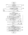
- FIG. 10A is a flowchart for explaining an operation procedure of periodic processing using the periodic addition value CI (k, Co) in the radar apparatus 1 according to the first embodiment.
- FIG. 10B is a flowchart for explaining the operation procedure of the sequential processing using the measurement addition value CI (k, Cr) in the radar apparatus 1 of the first embodiment.
- the periodic data acquisition unit 20 sets 1 as the initial values of the parameter Co, the parameter Cp, and the range bin k, and sets (Tp + 1) as the parameter Cu (S1).
- Tp is an integer of 1 or more.
- the periodic data acquisition unit 20 acquires the periodic addition value CI (k, Co) from the antenna system processing unit D1 and stores it in the periodic data memory 21 until the parameter Co is To and the range bin k is Tq (S2). ).
- Co is an integer that satisfies 1 ⁇ Co ⁇ To, and Tq is the maximum value of the range bin k (1 ⁇ k ⁇ Tq).
- the amplitude fluctuation width determination threshold value generation unit 22 calculates the amplitude Am (k, Co) for each range bin k of the periodic addition value CI (k, Co) stored in the periodic data memory 21 according to Expression (7) (S3). ).
- the amplitude fluctuation width determination threshold value generation unit 22 calculates the amplitude Am (k, Cu) calculated in the Cuth out of the total Co amplitudes Am (k, Co) calculated according to Equation (7) and the amplitude Am.
- the amplitude difference between the latest Tp amplitudes Am (k, Cu-Cp) to Am (k, Cu-1) calculated before the calculation of (k, Cu) is summed according to the equation (8) (To- Tp) operations are performed.
- the amplitude variation determination threshold generation unit 22 uses the maximum absolute value A max (k, Cu) of the total (To ⁇ Tp) amplitude differences. Then, a determination threshold A thr (k) for each range bin k for detecting the presence or absence of an object is calculated (S6). After step S6, when the range bin k is less than Tq (S7, YES), the amplitude fluctuation width determination threshold value generation unit 22 increments the range bin k by 1, and performs the operation of step S6 until the range bin k becomes Tq. repeat. After the range bin k reaches Tq, the periodic process shown in FIG.
- the measurement data acquisition unit 23 sets 1 as the initial value of the parameter Cr and the range bin k (S11).
- the measurement data acquisition unit 23 sequentially acquires the measurement addition value CI (k, Cr) from the antenna system processing unit D1 until the parameter Cr is (Tp + 1) and the range bin k becomes Tq (S12).
- the measurement data acquisition unit 23 stores the total (Tp + 1) measurement addition values CI (k, Cr) in the measurement data memory 24 every time it acquires the total (Tp + 1) measurement addition values CI (k, Cr). To do.
- the amplitude fluctuation width detection determination unit 25 calculates the amplitude Am (k, Cr) for each range bin k of the measurement added value CI (k, Cr) stored in the measurement data memory 24 according to the equation (13) (S13). .
- the amplitude fluctuation width detection determination unit 25 calculates the amplitude Am (k, Tp + 1) calculated in the (Tp + 1) th among the total (Tp + 1) amplitudes Am (k, Cr) calculated according to the equation (13). Then, a total of Tp amplitude differences with the latest Tp amplitudes Am (k, 1) to Am (k, Tp) calculated before calculating the amplitude Am (k, Tp + 1) are calculated according to the equation (14). .
- the amplitude fluctuation width detection determination unit 25 calculates the absolute value A rt_max (k) of the absolute value of each amplitude difference according to the equation (15) based on the total Tp amplitude differences calculated according to the equation (14). (S14). The amplitude variation detection unit 25 determines the absolute value A rt — max (k) of the absolute value of the amplitude difference calculated according to Equation (15) and the determination threshold calculated by the amplitude variation determination threshold generation unit 22 according to Equation (11). A thre (k) is compared (S15).
- the amplitude variation detection unit 25 detects the presence / absence of the target object. It is determined that an object has been detected (S16). The amplitude fluctuation range detection determination unit 25 outputs the determination result of step S16 to the object detection output unit 26.
- the amplitude variation detection unit 25 determines whether there is an object as a target. As a result of detection, it is determined that no object has been detected (S17).
- the amplitude fluctuation range detection determination unit 25 outputs the determination result of step S17 to the object detection output unit 26.
- step S16 or S17 when the range bin k is less than Tq (S18, YES), the amplitude fluctuation width detection determining unit 25 increments the range bin k by 1, and steps S13 to S16 until the range bin k becomes Tq. Alternatively, the operations in steps S13 to S17 are repeated. After the range bin k reaches Tq, the sequential processing shown in FIG. 10B ends.
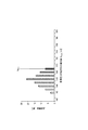
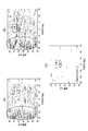
- FIG. 11 is a graph showing the relationship between the power value of the measured addition value CI (k, Cr) and the appearance frequency at which the power value is obtained.
- the horizontal axis in FIG. 11 indicates the power value [dB] of the measured addition value CI (k, Cr), and the vertical axis in FIG. 11 indicates the appearance frequency [number] at which the power value is obtained. That is, FIG. 11 is a graph represented using the output value of the antenna system processing unit D1, and is data before processing in the object detection processing unit 10.
- the power value of the measured addition value CI (k, Cr) in the actual environment is shown, and specifically, a total of 100 when there is a person and no person at a position 70 m away from the radar apparatus 1.
- a histogram of power values of the measured addition values CI (k, Cr) is shown.
- the power value of the measured addition value CI (k, Cr) is attenuated and affected by noise or clutter (reflected wave). Since the power value is attenuated, it can be seen that it is duplicated with data without a person. In addition, when a person is present at a position far away from the radar apparatus 1 and when a person is not present, the power value when the person is present is high and the appearance frequency is relatively high.
- the present inventors for example, when a person is present in the measurement range of the radar apparatus 1, for example, the amount of fluctuation in the amplitude of the measured addition value CI (k, Cr) changes periodically and the person exists. It has been noted that the frequency of the measured addition value CI (k, Cr) is high as compared with the case where it is not.
- the amplitude fluctuation amount of the measured addition value CI (k, Cr) changes periodically compared to when no person is present, and furthermore, the measurement addition value CI.
- the frequency with large amplitude of (k, Cr) is high.
- the maximum amplitude difference is obtained by obtaining the maximum amplitude fluctuation amount in the past Tp (corresponding to one cycle), and the amplitude value is larger when a person exists.
- the maximum amplitude difference from the past Tp in FIG. 12 is calculated, a large value is shown. From the above, the difference between when a person exists and when it does not exist becomes clear.
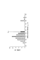
- the radar apparatus 1 uses a determination threshold A thr (for determining the detection result of the presence or absence of an object (for example, a person) as a target by the periodic processing and sequential processing shown in FIGS. k) (for example, 149 [dB] in FIG. 12) can be set and the detection result of the presence / absence of a person can be determined with high accuracy using the determination threshold A thr (k), so that deterioration in detection accuracy of the person can be suppressed ( (See FIG. 12).
- a determination threshold A thr for determining the detection result of the presence or absence of an object (for example, a person) as a target by the periodic processing and sequential processing shown in FIGS. k) (for example, 149 [dB] in FIG. 12) can be set and the detection result of the presence / absence of a person can be determined with high accuracy using the determination threshold A thr (k), so that deterioration in detection accuracy of the person can be suppressed (See FIG. 12).
- Figure 12 is a graph showing in the case where there is no case and persons exist person, the relationship between the frequency where the maximum value A Rt_max maximum value A Rt_max the absolute value of the amplitude difference of the absolute value of the amplitude difference is obtained It is.
- the horizontal axis of FIG. 12 indicates the power value [dB] of the maximum amplitude difference A max for the past Tp with respect to the measured addition value CI (k, Cr), and the vertical axis of FIG. Number].
- FIG. 12 shows the power value of the measured addition value CI (k, Cr) in the actual environment, specifically, a total of 100 when there is a person and no person at a position 70 m away from the radar apparatus 1.
- a histogram of power values of the measured addition values CI (k, Cr) is shown.
- the radar apparatus 1 determines whether or not there is an object (for example, a person) as a target by performing the periodic processing using the total To periodic addition values CI (k, Co) illustrated in FIG.
- the determination threshold A thre (k) for determining the detection result can be set, and further, the determination is performed by the sequential processing using the total (Tp + 1) measurement addition values CI (k, Cr) shown in FIG.
- the detection result of the presence / absence of a person is determined using the threshold value A thre (k).
- the radar apparatus 1 periodically changes the amplitude fluctuation range (amplitude fluctuation amount) of the measured addition value CI (k, Cr) in the person, and further, the amplitude when the person exists is determined by the person.
- the amplitude variation characteristic of a person that is relatively large compared to the amplitude when it does not exist deterioration in detection accuracy of an object including a person can be suppressed, which is described in Patent Document 1 and Non-Patent Document 1 described above.
- An object for example, a person
- the radar apparatus 1 of this embodiment has been described as determining the detection result of the presence or absence of an object using one variation period T human as the period for a single measurement, one variation period T human Instead, the determination may be made using several fluctuation cycles T human .
- the radar apparatus 1 determines the detection result of the presence / absence of an object using the fluctuation range of each amplitude Am of the periodic addition value CI (k, Co) and the measurement addition value CI (k, Cr). Even if the detection result of the presence / absence of an object is determined using not only the fluctuation range of the amplitude Am but also the fluctuation range of the power value Pm, the same effect can be obtained.
- Equation (7) is Equation (17)
- Equation (8) is Equation (18)
- Equation (10) is Equation (19)
- Equation (11) is Equation (20)
- Formula (13) is replaced with Formula (21)
- Formula (14) is replaced with Formula (22)
- Formula (15) is replaced with Formula (23).
- the radar apparatus 1 of the present embodiment has been described as a configuration having one antenna system processing unit D1 in the radar receiving unit Rx, the radar receiving unit Rx may include a plurality of antenna system processing units.
- the radar receiving unit Rx may determine the detection result of the presence or absence of an object individually using the output (periodic addition value, measurement addition value) from each antenna system processing unit in the object detection processing unit 10, Alternatively, the detection result of the presence / absence of an object may be determined when the determination results using outputs from all antenna system processing units match.
- FIG. 13 is a block diagram schematically showing the internal configuration of the radar apparatus 1A of the second embodiment.
- FIG. 14 is a block diagram simply showing an internal configuration of a radar apparatus 1AF that transmits a radar transmission signal whose frequency is modulated by the radar transmission unit TxF in the second embodiment.
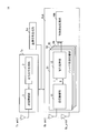
- FIG. 15 is a block diagram showing in detail the internal configuration of the radar receiver RxA of the radar apparatus 1A of the second embodiment.
- the radar apparatus 1A receives a reflected wave signal, which is a radar transmission signal reflected by an object (not shown) as a target, in a plurality of antenna system processing units D1 to D4 each having a receiving antenna.
- the radar apparatus 1A detects the presence / absence of the target object and the position of the object by performing signal processing on the reflected wave signal received by each receiving antenna.
- the radar receiving unit RxA has a total of four antenna system processing units D1 to D4 each connected with one receiving antenna, and an object detection processing unit 10A.
- the number of antenna system processing units in the radar receiver RxA of the radar apparatus 1A of the present embodiment is not limited to four, and may be two or more.
- each antenna system processing unit D1 to D4 has the same configuration, in this embodiment, the antenna system processing unit D1 will be described as an example, and the same applies to each of the following embodiments.
- FIG. 14 can be used as a configuration diagram when the frequency-modulated radar transmission signal (for example, chirp pulse) of FIG. 2 is used.
- the frequency-modulated radar transmission signal for example, chirp pulse
- Each of the antenna system processing units D1F to D4F calculates 2Nf Doppler frequency components f s ⁇ for each beat frequency f b every Nc periods (Tc ⁇ Nc) of the transmission cycle Tc by the calculation of Expression (24).
- Corresponding coherent addition results FT_CI Nant (f b , ⁇ Nf + 1, w) to FT_CI Nant (f b , Nf, w) are obtained.
- the radar receiver Rx periodically calculates each transmission cycle Tr of the radar transmission signal as a signal processing section in the signal processing unit of each antenna system processing unit D1 to D4.
- the operation of each of the antenna system processing units D1 to D4 is the same as that of the antenna system processing unit D1 in the radar receiving unit Rx of the radar apparatus 1 according to the first embodiment, and a description thereof will be omitted.
- the object detection processing unit 10A includes a regular data acquisition unit 20, a regular data memory 21, an amplitude fluctuation range determination threshold value generation unit 22, a measurement data acquisition unit 23, a measurement data memory 24, an amplitude fluctuation range detection determination unit 25, and a measurement data selection unit. 31, a distance / orientation profile generation unit 30 and an object detection output unit 26.
- the periodic data acquisition unit 20, the measurement data acquisition unit 23, the measurement data memory 24, and the distance / orientation profile generation unit 30 of the object detection processing unit 10A have outputs from the addition units of the signal processing units of the antenna system processing units D1 to D4. Certain added values CI 1 (k, m) to CI 4 (k, m) are inputted.
- the radar receiving unit has a plurality of antenna system processing units
- CI 4 (k, m) is input.
- the periodic data acquisition unit 20 includes the periodic addition values CI 1 (k, Co) to CI 4 (k, Co) acquired from a total of four antenna system processing units D1 to D4.
- the periodic addition values obtained from any of the antenna system processing units may be stored in the periodic data memory 21, or the periodic addition values obtained from all the antenna system processing units may be stored in the periodic data memory 21. It may be stored.
- the measurement data selection unit 31 selects the range bin k or the range of the range bin k corresponding to the determination result according to the determination result indicating that the amplitude fluctuation width detection determination unit 25 has detected the object, and stores it in the measurement data memory 24. .
- the distance / azimuth profile generation unit 30 Based on the range bin k selected by the measurement data selection unit 31, the distance / azimuth profile generation unit 30 performs measurement addition from the measurement data memory 24 as outputs of the respective antenna system processing units D1 to D4 corresponding to the selected range bin k.
- the values CI 1 (k, m) to CI 4 (k, m) are acquired.
- the distance azimuth profile generation unit 30 estimates the azimuth angle of the reflected wave signal in the arrival direction by using the phase difference between the reception antennas of the reflected wave signal reflected by the target object.
- the azimuth angle estimation processing in the distance and azimuth profile generation unit 30 will be described using, for example, the Fourier method, but is not limited to the Fourier method, and for example, the Capon method may be used.
- the distance and azimuth profile generation unit 30 performs object calculation by calculating the square of the inner product of the correlation vector h (k, Co) and the previously stored direction vector a ( ⁇ u ) according to the equation (26).
- the direction vector correlation power F out (k, Co, ⁇ u ) in the reflected wave signal reflected is calculated.
- the direction vector a ( ⁇ q ) is a Na-th order column vector representing the complex response of each receiving antenna when the reflected wave signal reflected by the object arrives from the direction of the azimuth angle ⁇ u .
- the direction vector a ( ⁇ u ) which is the complex response of each receiving antenna for each azimuth angle ⁇ u , is measured in advance, for example, in an anechoic chamber, and is phase difference information calculated geometrically according to the interval between the receiving antennas.
- it includes the coupling between the antenna elements between the receiving antennas and the deviation information of the amplitude error and the phase error, and the same applies to each embodiment described later.
- the azimuth angle ⁇ u is a variable that is changed at each predetermined interval ⁇ in the estimated range [ ⁇ min , ⁇ max ] of the arrival direction of the reflected wave signal in the radar apparatus 1A, and is represented by, for example, Expression (28).
- u is an integer from 0 to NU.
- NU is represented by Equation (29).
- floor [y] is a function that outputs the maximum integer value that does not exceed the real number y.
- the distance and azimuth profile generation unit 30 directional vector correlation power F DOA (k, Co, ⁇ for each range bin k selected by the measurement data selection unit 31 within the range of [ ⁇ min , ⁇ max ] of the azimuth angle ⁇ u.
- the maximum value (peak value) of u ) is detected.
- the distance and azimuth profile generation unit 30 provides an azimuth angle ⁇ u that gives a maximum value when the maximum value of the direction vector correlation power F DOA (k, Co, ⁇ u ) corresponding to the selected range bin k is equal to or greater than a predetermined threshold. Is estimated as the azimuth of the arrival direction of the reflected wave signal reflected by the object.
- the distance / azimuth profile generation unit 30 calculates the distance D (k) from the radar apparatus 1A to the target object according to the equation (16) using the range bin k selected by the measurement data selection unit 31.
- the distance / azimuth profile generation unit 30 outputs data of the distance D (k) and the azimuth angle ⁇ u to the object detection output unit 26.
- the radar apparatus 1A can obtain the effects of the radar apparatus 1 according to the first embodiment, and furthermore, the added value CI (k, Co) as the outputs of the plurality of antenna system processing units D1 to D4. based on the direction vector correlation power using a correlation vector h (k, Co) comprising the distance D (k) and azimuth theta u from the radar apparatus 1A to the object can be estimated with high accuracy.
- the radar apparatus 1A can limit the range bin k for estimating the azimuth angle ⁇ u by selecting the range bin k from which the amplitude fluctuation width detection determination unit 25 has determined the object detection result in the measurement data selection unit 31.
- the amount of computation of the distance / orientation profile generation unit 30 can be reduced, and the power consumption of the radar apparatus 1A can be reduced.
- the radar apparatus 1A calculates the direction vector correlation power using the range bin k in which the amplitude fluctuation width detection determination unit 25 determines the detection result that the object exists, but determines the detection result that the object does not exist.
- the direction vector correlation power may be calculated using the range bin k. Thereby, the radar apparatus 1A can grasp a wide range of situations around the radar apparatus 1A by calculating the direction vector correlation power related to the situation around the radar apparatus 1A.
- FIG. 16 is a graph showing an example of the added value CI on the IQ plane when a person is present.
- the horizontal axis in FIG. 16 indicates the I axis on the IQ plane, and the vertical axis in FIG. 16 indicates the Q axis on the IQ plane.
- the amplitude or power value of the measured addition value CI (k, Cs) (for example, 1 ⁇ Cs ⁇ 50) is seen to fluctuate on the IQ plane.
- the measurement addition value CI (k, Cs) includes the amplitude or power value of the measurement addition value CI (k, Cs) when no person exists, the measurement addition value CI ( It is necessary to remove the component of the amplitude or power value of k, Cs).
- the diamond point (solid line) index indicates the original data of the measured addition value CI (k, Cs), and the square point (see dotted line portion) index is the measured addition value CI (k, Cs).
- the square point index is plotted on a certain value (see dotted line) on the IQ plane, it corresponds to the measured addition value CI (k, Cs) when no person is present.
- the complex average distance direction profile generation unit 40b described later subtracts the complex average CI ave (k, Cs) from the original data of the measurement addition value CI (k, Cs) (for example, 1 ⁇ Cs ⁇ 50) on the IQ plane. Then, by calculating the complex average difference, the component when the person does not exist is removed, and the fluctuation of the measured addition value CI (k, Cs) that occurs when the person exists is obtained. That is, the average value for the past 10 pieces is obtained, and the average value obtained from the past 10 pieces of data is subtracted to remove the component when no person is present.
- FIG. 17 is a block diagram showing in detail the internal configuration of the radar receiver RxB of the radar apparatus 1B of the third embodiment.
- FIG. 18 is a block diagram showing in detail the internal configuration of the complex average distance and azimuth profile generation units 40a and 40b.
- the same reference numerals are given to the same parts as those of the radar apparatus 1 or 1A of the first or second embodiment. Omitted or simplified, different contents will be described.
- the radar apparatus 1B includes a reference signal generation unit Lo and a radar transmission unit Tx shown in FIG. 1 or FIG. 13, and a radar reception unit RxB shown in FIG.
- the radar receiver RxB includes a plurality (for example, four) of antenna system processors D1 to D4 and an object detection processor 10B shown in FIG.
- the description thereof is omitted.
- the object detection processing unit 10B includes a regular data acquisition unit 20, a regular data memory 21, an amplitude fluctuation range determination threshold value generation unit 22, a measurement data acquisition unit 23, a measurement data memory 24, an amplitude fluctuation range detection determination unit 25, and a measurement data selection unit. 31, complex average distance direction profile generation units 40 a and 40 b, distance direction profile memories 41 a and 41 b, a determination threshold value generation unit 42, an object detection determination unit 43, and an object detection output unit 26.
- the complex average distance direction profile generation unit 40a (40b) illustrated in FIG. 18 includes a complex average calculation unit 400a (400b), a complex data memory 401a (401b), a complex average difference calculation unit 402a (402b), and a distance direction profile generation unit 30a. (30b).
- the complex average distance and azimuth profile generation unit 40a as an example of the first distance and azimuth profile generation unit includes a periodic addition value CI (k, k, as outputs of the four antenna system processing units D1 to D4 stored in the periodic data memory 21.
- CI periodic addition value
- the distance orientation profile of the periodic addition value CI (k, Cs) is calculated.
- Cs is an integer satisfying 1 ⁇ Cs ⁇ Ts, and Ts is an integer equal to or smaller than To.
- the complex average calculation unit 400a outputs Ts periodic addition values as outputs of the four antenna system processing units D1 to D4, that is, the periodic addition value CI 1 obtained for each range bin k over a transmission cycle of Ts ⁇ Np ⁇ Tr.
- the complex average CI uu ave (k) is calculated according to the equation (30).
- the complex average calculation unit 400a outputs the complex average CI uu ave (k), which is the calculation result of Expression (30), to the complex average difference calculation unit 402a.
- the complex data memory 401a has a periodic addition value for Ts times as outputs of the four antenna system processing units D1 to D4, that is, a periodic addition value CI 1 obtained for each range bin k over a transmission cycle of Ts ⁇ Np ⁇ Tr. k, Cs) to CI 4 (k, Cs) are stored.
- the complex average difference calculation unit 402a uses the complex average CI uu ave (k) and the periodic addition values CI 1 (k, Cs) to CI 4 (k, Cs) stored in the complex data memory 401a. According to (31), the complex average difference CI uu sa (k, Cs) for each antenna system processing unit is calculated. The complex average difference calculation unit 402a outputs the complex average difference CI uu sa (k), which is the calculation result of Expression (31), to the distance / orientation profile generation unit 30a.
- the distance orientation profile generation unit 30a stores a total of four complex averages CI uu sa (k) as correlation vectors h (k, Cs) in advance as correlation vectors h (k, Cs) (see Expression (25)).
- the distance direction profile HM (k, Cs, cc) in the reflected wave signal reflected by the object is calculated by square calculation of the inner product with the direction vector a (cc) that has been stored (see equation (32)). Since the direction vector a (cc) is the same as the direction vector a ( ⁇ u ) in the second embodiment described above, the description thereof is omitted.
- cc represents an azimuth angle and corresponds to the azimuth angle ⁇ u in the second embodiment.
- the distance and azimuth profile generation unit 30a calculates for each range bin k and azimuth angle cc according to Equation (32) until the parameter Co in the first embodiment reaches To (see FIG. 5B) (To-Ts).
- the distance orientation profiles HM (k, Cs, cc) are stored in the distance orientation profile memory 41a.
- the distance direction profile memory 41a stores (To-Ts) number of distance direction profiles HM (k, Cs, cc) calculated by the complex average distance direction profile generation unit 40a.
- the determination threshold value generation unit 42 as an example of the second determination threshold value generation unit calculates a cumulative probability distribution of the distance direction profile based on the distance direction profile for each range bin k and azimuth angle cc stored in the distance direction profile memory 41a. To do.
- the determination threshold generation unit 42 uses a range bin k for detecting the presence / absence of an object as a target with a power value at which the cumulative probability distribution of the distance orientation profile for each range bin k and azimuth angle cc is a predetermined value (for example, 98%) or more.
- a second determination threshold value HM_bg (k, cc) for each azimuth angle cc.
- the determination threshold generation unit 42 outputs the second determination threshold HM_bg (k, cc) to the object detection determination unit 43.
- the complex average calculation unit 400b as an example of the second distance / azimuth profile generation unit includes the measurement addition values CI (k, Cs) as outputs of the four antenna system processing units D1 to D4 stored in the measurement data memory 24. Among these, by calculating the complex average and the complex average difference for each range bin Cv (ii) selected by the measurement data selection unit 31, the distance orientation profile of the measurement addition value CI (k, Cs) is calculated.
- ii is an integer satisfying 1 ⁇ ii ⁇ Tv, and Tv indicates the maximum value of the range bin selected by the measurement data selection unit 31.
- the complex average calculation unit 400b measures Ts as the output of the four antenna system processing units D1 to D4, that is, the measurement addition obtained for each range bin Cv (ii) over the transmission cycle of Ts ⁇ Np ⁇ Tr. Using the values CI 1 (Cv (ii), Cs) to CI 4 (Cv (ii), Cs), the complex average CI uu ave (Cv (ii)) is calculated according to Equation (33). The complex average calculation unit 400b outputs the complex average CI uu ave (Cv (ii)), which is the calculation result of Expression (33), to the complex average difference calculation unit 402b.
- the complex data memory 401b has Ts measurement addition values as outputs of the four antenna system processing units D1 to D4, that is, measurement addition values obtained for each range bin Cv (ii) over a transmission cycle of Ts ⁇ Np ⁇ Tr. CI 1 (Cv (ii), Cs) to CI 4 (Cv (ii), Cs) are stored.
- the complex average difference calculation unit 402b includes a complex average CI uu ave (Cv (ii)) and measured addition values CI 1 (Cv (ii), Cs) to CI 4 (Cv (ii)) stored in the complex data memory 401b. , Cs) and the complex average difference CI uu sa (Cv (ii), Cs) is calculated according to Equation (34).
- the complex average difference calculation unit 402b outputs the complex average CI uu sa (Cv (ii)), which is the calculation result of Expression (34), to the distance / orientation profile generation unit 30b.
- the distance / azimuth profile generation unit 30b uses a total of four complex averages CI uu sa (Cv (ii)) as correlation vectors h (Cv (ii), Cs) (see Expression (25)), and correlation vectors h (Cv ( ii), Cs) and a distance direction profile HM (Cv (ii), Cs, cc) in the reflected wave signal reflected by the object is calculated by square calculation of the inner product of the direction vector a (cc) stored in advance. (See Equation (35)).
- the distance direction profile generation unit 30b stores the range direction profile HM (Cv (ii), Cs, cc) calculated for each range bin Cv (ii) and the direction angle cc in the distance direction profile memory 41b according to the equation (31).
- the distance direction profile memory 41b stores the distance direction profile HM (Cv (ii), Cs, cc) calculated by the complex average distance direction profile generation unit 40b.
- the object detection determination unit 43 includes the distance direction profile HM (Cv (ii), Cs, cc) stored in the distance direction profile memory 41b and the second determination threshold value HM_bg (k, cc) set by the determination threshold value generation unit 42. And compare.
- the object detection determination unit 43 includes the distance direction profile HM (Cv (ii), Cs, cc) stored in the distance direction profile memory 41b and the second determination threshold value HM_bg (k, cc) set by the determination threshold value generation unit 42. And the detection result of the presence or absence of the target object (details will be described later with reference to FIG. 20).
- the object detection determination unit 43 outputs the determination result of the detection result of the presence / absence of an object to the object detection output unit 26.
- FIG. 19 is a flowchart for explaining an operation procedure of periodic processing using the periodic addition value in the radar apparatus of the third embodiment.
- FIG. 20 is a flowchart for explaining an operation procedure of sequential processing using the measured addition value in the radar apparatus according to the third embodiment.
- the periodic data acquisition unit 20 sets 1 as an initial value of the parameter Co, the parameter Cp, the parameter Cs, and the range bin k, and sets (Tp + 1) as the parameter Cu (S21).
- Tp is an integer of 1 or more.
- the complex average distance orientation profile generation unit 40a acquires the periodic addition value CI (k, Cs) from the periodic data memory 21 until the parameter Cs reaches Ts (S22).
- Co is an integer that satisfies 1 ⁇ Co ⁇ To
- Tq is the maximum value of the range bin k (1 ⁇ k ⁇ Tq).
- the complex average distance orientation profile generation unit 40a increments the parameter Cs by 1, and repeats the operation of step S22 until the parameter Cs reaches Ts.
- the complex average distance direction profile generation unit 40a uses the Ts periodic addition values CI (k, Cs) from the respective antenna system processing units D1 to D4, A complex average CI uu ave (k) is calculated according to Equation (30) (S24). Further, the complex average distance orientation profile generation unit 40a calculates the complex average CI uu ave (k) and the periodic addition values CI 1 (k, Cs) to CI 4 (k, Cs) stored in the complex data memory 401a. Then, the complex average difference CI uu sa (k, Cs) for each antenna system processing unit is calculated according to Equation (31) (S25).
- the complex average distance orientation profile generation unit 40a uses the total of four complex averages CI uu sa (k) as correlation vectors h (k, Cs), and the direction stored in advance as the correlation vector h (k, Cs).
- the distance direction profile HM (k, Cs, cc) in the reflected wave signal reflected by the object is calculated by the square calculation of the inner product with the vector a (cc) (see S26, equation (32)).
- the complex average distance azimuth profile generation unit 40a increments the range bin k by 1 and continues to steps S24 to S26 until the range bin k becomes Tq. Repeat the operation.
- the complex average distance orientation profile generation unit 40a increments the parameter Co by 1 and the parameter Co is
- the periodic addition value CI (k, Co) used for the operations in steps S24 to S27 is shifted one by one until the time reaches To, and the operations in steps S24 to S27 are repeated.
- the determination threshold value generation unit 42 After the parameter Co becomes To (S28, NO), the determination threshold value generation unit 42 accumulates the distance azimuth profile based on the distance azimuth profile for each range bin k and azimuth cc stored in the distance azimuth profile memory 41a. A probability distribution is calculated (S29).
- the determination threshold generation unit 42 uses a range bin k for detecting the presence / absence of an object as a target with a power value at which the cumulative probability distribution of the distance orientation profile for each range bin k and azimuth angle cc is a predetermined value (for example, 98%) or more. And it sets as 2nd determination threshold value HM_bg (k, cc) for every azimuth angle cc (S30).
- the determination threshold value generation unit 42 outputs the second determination threshold value HM_bg (k, cc) to the object detection determination unit 43. After step S30, the periodic process shown in FIG. 19 ends.
- the measurement data acquisition unit 23 sets 1 as initial values of the parameter Cr, the parameter Cs, the parameter Cv, the parameter k, and the parameter ii (S31).
- the operations in steps S12 to S18 after step S31 are the same as the operations in steps S12 to S18 shown in FIG.
- the complex average distance and azimuth profile generation unit 40b performs measurement as outputs of the four antenna system processing units D1 to D4 stored in the measurement data memory 24.
- the range bin Cv (ii) selected by the measurement data selection unit 31 is acquired (S32).
- the parameter ii is an integer that satisfies 1 ⁇ ii ⁇ Tv.
- the complex average distance and azimuth profile generation unit 40b performs the measurement addition values CI 1 (Cv (ii), Cs) to CI 4 (Cv (ii) for each range bin Cv (ii) acquired in step S32 until the parameter Cs becomes Ts. ), Cs) is acquired from the measurement data memory 24 (S33).
- Cs is an integer satisfying 1 ⁇ Cs ⁇ Ts.
- the complex average distance and azimuth profile generation unit 40b outputs Ts measurement addition values CI 1 (Cv (ii), Cs) to CI 4 (Cv (ii), Cs) as outputs of the antenna system processing units D1 to D4. Then, the complex average CI uu ave (Cv (ii)) is calculated according to the equation (33) (S34).
- the complex average distance direction profile generation unit 40b includes the complex average CI uu ave (Cv (ii)) and the measured addition values CI 1 (Cv (ii), Cs) to CI 4 (CI 4 ) stored in the complex data memory 401b.
- Cv (ii), Cs) is used to calculate the complex average difference CI uu sa (Cv (ii), Cs) according to the equation (34) (S35).
- the complex average distance direction profile generation unit 40b uses the total four complex averages CI uu sa (Cv (ii)) as the correlation vectors h (Cv (ii), Cs), and the correlation vectors h (Cv (ii),
- the distance direction profile HM (Cv (ii), Cs, cc) in the reflected wave signal reflected by the object is calculated by square calculation of the inner product of Cs) and the direction vector a (cc) stored in advance (S36). , See formula (35)).
- the object detection determination unit 43 calculates the distance / orientation profile HM (Cv (ii), Cs, cc) calculated in step S36 and the second determination threshold HM_bg (k, cc) set in step S30 shown in FIG. Are compared for each azimuth angle cc (S37).
- the object detection determination unit 43 determines whether there is an object as a target. As a detection result, it is determined that an object has been detected (S38). The object detection determination unit 43 outputs the determination result of step S38 to the object detection output unit 26.
- the object detection determination unit 43 sets the target object It is determined that no object has been detected as a detection result of the presence or absence of (S39).
- the amplitude fluctuation range detection determination unit 25 outputs the determination result of step S17 to the object detection output unit 26.
- step S38 or S39 when the parameter ii of the range bin Cv (ii) is less than Tv (S40, NO), the complex average distance / azimuth profile generation unit 40b increments the parameter ii by 1, and the range bin Cv (ii) Steps S34 to S36 are repeated until the parameter ii of) reaches Tv. After the parameter ii of the range bin Cv (ii) becomes Tv, the sequential processing shown in FIG. 20 ends.
- FIG. 21A is a graph showing an example of a measurement result of a person in a conventional radar device.
- FIG. 21B shows an example of a human measurement result when a person is extracted by using a complex average, but the second determination threshold HM_bg (k, cc) is not used in the radar apparatus of the third embodiment. It is a graph which shows.
- FIG. 21C is a graph illustrating an example of a measurement result of a person when the second determination threshold HM_bg (k, cc) is used in the radar apparatus according to the third embodiment.
- Each horizontal axis in FIGS. 21A to 21C represents an azimuth angle [deg], and each vertical axis in FIGS. 21A to 21C represents a distance [m].
- FIGS. 21A to 21C in order to clarify the effect of the radar apparatus 1B of the present embodiment, the effect of the operation overlapping with the radar apparatus 1 of the first embodiment is described. Are omitted, and the effects of the operations of the complex average distance / azimuth profile generation units 40a and 40b, the distance / direction profile memories 41a and 41b, the determination threshold generation unit 42, and the object detection determination unit 43 of the radar apparatus 1B will be described.
- FIG. 21A there is a person who is a target far away from the radar apparatus 1B, and the power value of the measured addition value CI (k, Cr) is attenuated and buried in noise or clutter. Is difficult to detect.
- the distance detection profile HM (Cv (ii), Cs, cc) and the second determination threshold HM_bg (k, cc) in the reflected wave signal reflected by the object are detected by the object detection determination unit 43.
- the result of detection of the presence or absence of an object using the comparison result is shown. Accordingly, in the graph shown in FIG. 21C, the influence of an obstacle (for example, a building) having a large power value other than a person is removed, and compared with the graphs shown in FIG. 21A and FIG. The person detection accuracy in the apparatus 1B is further improved.
- the radar apparatus 1B can obtain the effects of the radar apparatus 1 according to the first embodiment, and can further obtain the periodic addition value and the measurement addition value as the outputs of the plurality of antenna system processing units D1 to D4.
- a complex average distance azimuth profile is calculated using the correlation vector and the direction vector included, and the detection result of the presence / absence of an object is determined according to the comparison result between the second determination threshold and the calculated complex average distance azimuth profile.
- the radar apparatus 1B can further improve the detection accuracy of an object (for example, a person) as a target by removing the influence of an obstacle (for example, a building) whose power value is large other than a person, for example.
- an object for example, a person
- an obstacle for example, a building
- the determination threshold generation unit 42 sets the power value that satisfies the cumulative probability of 98% or more of the cumulative probability distribution of the distance orientation profile for each range bin k and azimuth angle cc to the second determination threshold HM_bg (k, cc).
- the setting criterion for example, cumulative probability distribution
- the second determination threshold HM_bg (k, cc) may be changed according to the acquisition status of the regular data.
- FIG. 19 is a block diagram illustrating in detail the internal configuration of the radar receiver RxF of the radar apparatus 1C according to the fourth embodiment.
- the same components as those of the radar device 1 of the first embodiment are denoted by the same reference numerals, and description thereof is omitted or simplified. The different contents will be described.
- the radar apparatus 1C switches the determination threshold used for the person detection determination in the radar apparatus 1 according to the first embodiment according to the state where the radar apparatus 1C is placed, thereby determining the determination threshold.
- the determination threshold is acquired from the database, and object detection with few false detections can be performed.
- the radar apparatus 1C of the present embodiment can acquire a determination threshold suitable for the environment in a state where the determination threshold can be acquired from the environment.
- the radar apparatus 1C according to the present embodiment is difficult to use because the data that is periodically acquired as in the first embodiment is moved in addition to the state in which the radar apparatus 1C is fixed. Even in a state in which the radar apparatus 1C cannot be acquired, by performing person detection using the determination threshold existing in the database, the radar apparatus 1C can be used even in a situation where it is not fixed.
- the radar apparatus 1C includes a reference signal generation unit Lo and a radar transmission unit Tx shown in FIG. 1, and a radar reception unit RxF shown in FIG.
- the radar receiving unit RxF includes one antenna system processing unit D1 and an object detection processing unit 10C shown in FIG.
- the radar apparatus 1 ⁇ / b> C is installed as an example of an in-vehicle device mounted on a moving body (for example, a vehicle).
- a moving body for example, a vehicle.
- the operation of the antenna system processing unit D1 is the same as the operation of the antenna system processing unit D1 in the radar receiving unit Rx of the radar apparatus 1 of the first embodiment, description thereof is omitted.
- the object detection processing unit 10C includes a periodic data acquisition unit 20, a periodic data memory 21, an amplitude variation width determination threshold value generation unit 22, a measurement data acquisition unit 23, a measurement data memory 24, an amplitude variation width detection determination unit 25, and an object detection output unit. 26, a vehicle information acquisition unit 50, an operation control unit 51, a switching unit 52, and a threshold information memory 53.
- the vehicle information acquisition part 50 as an example of a movement condition acquisition part acquires the information regarding the vehicle in which the radar apparatus 1C was installed.
- the information regarding the vehicle is information indicating whether the vehicle is operating an engine or whether the vehicle is stopped, for example.
- the vehicle information acquisition unit 50 outputs information related to the vehicle to the operation control unit 51.
- the operation control unit 51 determines the determination threshold value calculated by the amplitude variation width determination threshold value generation unit 22 as a determination threshold value for determining the detection result of the presence or absence of an object according to the information about the vehicle obtained from the vehicle information acquisition unit 50.
- a thre (k) or a control signal for switching to the determination threshold value Z stored in advance in the threshold value information memory 53 is output to the switching unit 52.
- the operation control unit 51 when the operation control unit 51 outputs a control signal for switching to the determination threshold value A thr (k) calculated by the amplitude fluctuation width determination threshold value generation unit 22 to the switching unit 52, the operation control unit 51 periodically transmits the control signal to the periodic data acquisition unit 20.
- the measured value CI (k, Co) is acquired from the antenna system processing unit D1.
- the switching unit 52 as an example of the first switching unit is an amplitude variation width determination threshold value generation unit 22 as a determination threshold value for determining the detection result of the presence / absence of an object according to the control signal obtained from the operation control unit 51. Is switched to the determination threshold value A thre (k) calculated by or the determination threshold value Z stored in advance in the threshold value information memory 53, and is output to the amplitude variation detection unit 25.
- the switching unit 52 is, for example, a state where the vehicle engine is not operating as a state of the vehicle, because the vehicle is stopped. Therefore, the determination threshold value A thr calculated by the amplitude variation width determination threshold value generation unit 22 is used. The determination threshold A thre (k) is used on the assumption that (k) is highly likely. Further, for example, the switching unit 52 uses the determination threshold Z stored in the threshold information memory 53 if the operating state of the wheel is in the neutral state even if the vehicle engine is operating as the vehicle state.
- the threshold information memory 53 as an example of the first determination threshold storage unit stores a determination threshold Z measured in advance by simulation or actual measurement.
- the amplitude fluctuation range detection determination unit 25 uses the maximum value A max (k) of the absolute value of the amplitude difference calculated according to the equation (15) and the determination threshold A thr (k) or the determination threshold Z obtained from the switching unit 52. And compare. When the maximum absolute value A max (k) of the amplitude difference is larger than the determination threshold A thre (k) or the determination threshold Z, the amplitude fluctuation width detection determination unit 25 detects the presence / absence of the target object. It is determined that an object has been detected. The amplitude fluctuation width detection determination unit 25 outputs the determination result to the object detection output unit 26.
- the amplitude fluctuation width detection determination unit 25 determines whether there is an object as a target. As a detection result, it is determined that no object has been detected.
- the amplitude fluctuation width detection determination unit 25 outputs the determination result to the object detection output unit 26.
- FIG. 23 is a flowchart for explaining an operation procedure of periodic processing using the periodic data memory 21 or the threshold information memory 53 in the radar apparatus 1C of the fourth embodiment.
- the same operations as those in the flowchart of the periodic process illustrated in FIG. 10A are denoted by the same reference numerals, the description thereof is omitted or simplified, and different contents will be described.
- the vehicle information acquisition unit 50 acquires information about the vehicle on which the radar device 1C is installed and outputs the information to the operation control unit 51.
- the operation control unit 51 determines the determination threshold value calculated by the amplitude variation width determination threshold value generation unit 22 as a determination threshold value for determining the detection result of the presence or absence of an object according to the information about the vehicle obtained from the vehicle information acquisition unit 50.
- a thre (k) or a control signal for switching to the determination threshold value Z stored in advance in the threshold value information memory 53 is output to the switching unit 52.
- the operation control unit 51 sends the periodic measurement value to the periodic data acquisition unit 20.
- CI (k, Co) is acquired from the antenna system processing unit D1.
- the switching unit 52 performs a determination calculated by the amplitude variation width determination threshold generation unit 22 as a determination threshold for determining the detection result of the presence / absence of an object in accordance with the control signal obtained from the operation control unit 51.
- the threshold value A thre (k) or the judgment threshold value Z stored in advance in the threshold value information memory 53 is switched to and output to the amplitude fluctuation width detection judgment unit 25 (S41, S42).
- the operation control unit 51 causes the periodic data acquisition unit 20 to acquire the periodic measurement value CI (k, Co) from the antenna system processing unit D1 (S43, YES), the process is shown in FIG. 10B after step S43. The operations from steps S1 to S7 are executed.
- the operation control unit 51 does not cause the periodic data acquisition unit 20 to acquire the periodic measurement value CI (k, Co) from the antenna system processing unit D1
- the switching unit 52 sets the determination threshold value Z to the amplitude fluctuation width detection determination unit 25.
- the amplitude fluctuation width detection determination unit 25 uses the determination threshold value Z obtained from the switching unit 52 as a determination threshold value for determining the detection result of the presence or absence of an object (S44). ).
- the amplitude fluctuation width detection determination unit 25 uses the determination threshold A thr (k) calculated by the amplitude fluctuation width determination threshold generation unit 22 (S45). After step S45, the periodic process shown in FIG. 23 ends.
- the amplitude variation detection unit 25 determines the maximum absolute value A of the amplitude difference calculated according to the equation (15). max (k) is compared with the determination threshold A thre (k) or the determination threshold Z obtained from the switching unit 52. When the maximum absolute value A max (k) of the amplitude difference is larger than the determination threshold A thre (k) or the determination threshold Z, the amplitude fluctuation width detection determination unit 25 detects the presence / absence of the target object. It is determined that an object has been detected. The amplitude fluctuation width detection determination unit 25 outputs the determination result to the object detection output unit 26.
- the amplitude fluctuation width detection determination unit 25 determines whether there is an object as a target. As a detection result, it is determined that no object has been detected.
- the amplitude fluctuation width detection determination unit 25 outputs the determination result to the object detection output unit 26.
- the radar apparatus 1C of the present embodiment can obtain the effects of the radar apparatus 1 of the first embodiment, and even when installed as an example of an in-vehicle device mounted on a moving body (for example, a vehicle) By switching the determination threshold value in the regular process to the predetermined determination threshold value Z or the determination threshold value A thre (k) calculated by the amplitude fluctuation width determination threshold value generation unit 22 according to information on the vehicle (for example, the movement status of the vehicle). An appropriate value of the determination threshold for determining the detection result of the presence / absence of an object is obtained.
- the radar apparatus 1C can improve the detection accuracy of the target object even when the radar apparatus 1C is installed on the moving body, compared to the radar apparatus 1 of the first embodiment.
- the radar apparatus 1C can detect an object with few false detections by acquiring the determination threshold value from the database in a scene where the determination threshold value cannot be acquired from the environment by switching the determination threshold value. Further, the radar apparatus 1C can acquire a determination threshold suitable for the environment in a scene where the determination threshold can be acquired from the environment.
- the radar apparatus 1C is difficult to use because the data acquired periodically as in the first embodiment is moving because the vehicle is moving, and the acquisition of the determination threshold is difficult. By performing person detection using the existing determination threshold, the radar apparatus 1C can be used even in a situation where the radar apparatus 1C is not fixed.
- FIG. 24 is a block diagram illustrating in detail the internal configuration of the radar receiver RxD of the radar apparatus 1D according to the fifth embodiment.
- the radar apparatus 1B of the third embodiment is mounted on a moving body (for example, a vehicle) will be described.
- the radar apparatus 1D of the present embodiment switches the determination threshold used for the person detection determination in the radar apparatus 1B of the third embodiment according to the state where the radar apparatus 1D is placed, thereby determining the determination threshold.
- the determination threshold is acquired from the database, and object detection with few false detections can be performed.
- the radar apparatus 1D of the present embodiment can acquire a determination threshold suitable for the environment in a state where the determination threshold can be acquired from the environment.
- the radar apparatus 1D of the present embodiment is difficult to use because the data that is periodically acquired as in the first embodiment is moved because of the movement, in addition to the state in which the radar apparatus 1D is fixed. Even in a state in which the radar apparatus 1D cannot be acquired, by performing person detection using the determination threshold existing in the database, the radar apparatus 1D can be used even in a situation where the radar apparatus 1D is not fixed.
- the radar apparatus 1D of the present embodiment can also detect a person in the angular direction by having a plurality of antenna system processing units.
- the radar apparatus 1D includes a reference signal generation unit Lo and a radar transmission unit Tx shown in FIG. 1, and a radar reception unit RxD shown in FIG.
- the radar receiver RxD includes four antenna system processors D1 to D4 and an object detection processor 10D shown in FIG.
- the radar apparatus 1D is installed as an example of an in-vehicle device mounted on a moving body (for example, a vehicle).
- the object detection processing unit 10D includes a regular data acquisition unit 20, a regular data memory 21, an amplitude variation width determination threshold value generation unit 22, a measurement data acquisition unit 23, a measurement data memory 24, a measurement data selection unit 31, and an amplitude variation width detection determination unit.
- object detection output unit 26 complex average distance direction profile generation units 40a and 40b, distance direction profile memories 41a and 41b, determination threshold generation unit 42, object detection determination unit 43, vehicle information acquisition unit 50, operation control unit 51, Switching units 52 a and 52 and a threshold information memory 53 are included.
- the operations of the vehicle information acquisition unit 50 and the operation control unit 51 are the same as the operations of the vehicle information acquisition unit 50 and the operation control unit 51 in the object detection processing unit 10C of the radar receiver RxF of the radar apparatus 1C of the fourth embodiment. Therefore, the description will be omitted, and different contents will be described.
- the operation control unit 51 determines the determination threshold value calculated by the amplitude variation width determination threshold value generation unit 22 as a determination threshold value for determining the detection result of the presence or absence of an object according to the information about the vehicle obtained from the vehicle information acquisition unit 50.
- a thre (k) or a control signal for switching to the determination threshold value Z stored in advance in the threshold information memory 53D is output to the switching unit 52a.
- the operation control unit 51 calculates the second determination threshold value calculated by the determination threshold value generation unit 42 as a second determination threshold value for determining the detection result of the presence / absence of an object according to the information about the vehicle obtained from the vehicle information acquisition unit 50.
- the control signal for switching to 2 determination threshold value HM_bg (k, cc) or the 2nd determination threshold value Z2 previously stored in threshold value information memory 53D is output to the switch part 52b.
- the switching unit 52a as an example of the second switching unit is an amplitude variation width determination threshold value generation unit 22 as a determination threshold value for determining the detection result of the presence / absence of an object in accordance with the control signal obtained from the operation control unit 51. Is switched to the determination threshold value A thre (k) calculated by or the determination threshold value Z stored in advance in the threshold value information memory 53, and is output to the amplitude variation detection unit 25. In FIG. 24, an arrow from the operation control unit 51 to the switching unit 52a is not shown.
- the switching unit 52b as an example of the second switching unit includes a determination threshold generation unit 42 as a second determination threshold for determining the detection result of the presence / absence of an object in accordance with the control signal obtained from the operation control unit 51.
- the calculated second determination threshold HM_bg (k, cc) or the second determination threshold Z2 stored in advance in the threshold information memory 53D is switched to output to the object detection determination unit 43.
- an arrow from the operation control unit 51 to the switching unit 52b is not shown.
- the switching units 52a and 52b constitute a second switching unit.
- the threshold information memory 53D as an example of the second determination threshold storage unit stores a determination threshold Z and a second determination threshold Z2 measured in advance by simulation or actual measurement.
- the amplitude fluctuation width detection determination unit 25 determines the maximum value A max (k) of the absolute value of the amplitude difference calculated according to Equation (15) and the determination threshold A thr (k) or the determination threshold Z obtained from the switching unit 52a. And compare. When the maximum absolute value A max (k) of the amplitude difference is larger than the determination threshold A thre (k) or the determination threshold Z, the amplitude fluctuation width detection determination unit 25 detects the presence / absence of the target object. It is determined that an object has been detected. The amplitude fluctuation width detection determination unit 25 outputs the determination result to the measurement data selection unit 31.
- the amplitude fluctuation width detection determination unit 25 determines whether there is an object as a target. As a detection result, it is determined that no object has been detected.
- the amplitude fluctuation width detection determination unit 25 outputs the determination result to the measurement data selection unit 31.
- the object detection determination unit 43 calculates the distance / azimuth profile HM (Cv (ii), Cs, cc) calculated according to the equation (32) and the second determination threshold HM_bg (k, cc) obtained from the switching unit 52b. 2
- the determination threshold value Z2 is compared.
- the object detection determination unit 43 determines whether there is an object as a target. As a result of detection, it is determined that an object has been detected.
- the object detection determination unit 43 outputs the determination result to the object detection output unit 26.
- the object detection determination unit 43 sets the target object It is determined that no object has been detected as a result of detection of the presence or absence of.
- the object detection determination unit 43 outputs the determination result to the object detection output unit 26.
- FIG. 25 is a flowchart for explaining an operation procedure of periodic processing using the periodic data memory 21 or the threshold information memory 53D in the radar apparatus 1D of the fifth embodiment.
- the same operations as those in the flowchart of the periodic process shown in FIG. 19 are denoted by the same reference numerals, the description thereof is omitted or simplified, and different contents will be described.
- the vehicle information acquisition unit 50 acquires information related to the vehicle on which the radar device 1D is installed and outputs the information to the operation control unit 51.
- the operation control unit 51 determines the determination threshold value calculated by the amplitude variation width determination threshold value generation unit 22 as a determination threshold value for determining the detection result of the presence or absence of an object according to the information about the vehicle obtained from the vehicle information acquisition unit 50.
- a thre (k) or a control signal for switching to the determination threshold value Z stored in advance in the threshold information memory 53D is output to the switching unit 52a.
- the operation control unit 51 calculates the second threshold value calculated by the determination threshold value generation unit 42 as a second determination threshold value for determining the detection result of the presence / absence of an object according to the vehicle information obtained from the vehicle information acquisition unit 50.
- the control signal for switching to 2 determination threshold value HM_bg (k, cc) or the 2nd determination threshold value Z2 previously stored in threshold value information memory 53D is output to the switch part 52b.
- the switching unit 52a is determined by the amplitude variation width determination threshold value generation unit 22 as a determination threshold value for determining the detection result of the presence / absence of an object according to the control signal obtained from the operation control unit 51.
- the threshold value A thre (k) or the judgment threshold value Z stored in advance in the threshold value information memory 53 is switched to and output to the amplitude fluctuation width detection judgment unit 25 (S41, S42).
- the switching unit 52b uses the second determination threshold calculated by the determination threshold generation unit 42 as the second determination threshold for determining the detection result of the presence / absence of an object in accordance with the control signal obtained from the operation control unit 51. It switches to HM_bg (k, cc) or the second determination threshold value Z2 stored in advance in the threshold information memory 53D and outputs it to the object detection determination unit 43 (S41, S42).
- FIG. 16 shows after step S43. The operations from steps S21 to S28 are executed.
- the operation control unit 51 does not cause the periodic data acquisition unit 20 to acquire the periodic measurement values CI (k, Co) from the respective antenna system processing units D1 to D4, that is, the switching units 52a and 52b have the determination threshold value Z
- the second When the determination threshold value Z2 is output to the amplitude variation detection unit 25 and the object detection determination unit 43 (S43, NO), the amplitude variation detection unit 25 determines the determination threshold Z obtained from the switching unit 52a. It is used as a determination threshold value for determining the detection result of the presence or absence of an object (S44).
- the object detection determination unit 43 uses the second determination threshold value Z2 obtained from the switching unit 52b as a second determination threshold value for determining the detection result of the presence / absence of an object (S44). After step S44, the periodic process shown in FIG. 25 ends.
- the object detection determination unit 43 uses the second determination threshold HM_bg (k, cc) calculated by the determination threshold generation unit 42 as a second determination threshold for determining the detection result of the presence or absence of an object. Used (S45). After step S45, the regular processing shown in FIG. 25 ends.
- the amplitude variation detection unit 25 determines the maximum absolute value A max (k) of the amplitude difference calculated according to the equation (15). ) And the determination threshold value A thre (k) or the determination threshold value Z obtained from the switching unit 52a (S15).
- the amplitude fluctuation width detection determination unit 25 detects the presence / absence of the target object. It is determined that an object has been detected.
- the amplitude fluctuation width detection determination unit 25 outputs the determination result to the object detection output unit 26.
- the amplitude fluctuation width detection determination unit 25 determines whether there is an object as a target. As a detection result, it is determined that no object has been detected.
- the amplitude fluctuation width detection determination unit 25 outputs the determination result to the measurement data selection unit 31.
- the object detection determination unit 43 performs the distance determination profile HM (Cv (ii), Cs, cc) calculated according to the equation (32) and the second determination obtained from the switching unit 52b.
- the threshold HM_bg (k, cc) or the second determination threshold Z2 is compared (S37).
- the object detection determination unit 43 determines whether there is an object as a target. As a result of detection, it is determined that an object has been detected.
- the object detection determination unit 43 outputs the determination result to the object detection output unit 26.
- the object detection determination unit 43 is a target. As a result of detecting the presence or absence of an object, it is determined that no object has been detected.
- the amplitude fluctuation width detection determination unit 25 outputs the determination result to the object detection output unit 26.
- the radar apparatus 1D of the present embodiment can obtain the effects of the radar apparatus 1B of the third embodiment, and even when installed as an example of an in-vehicle device mounted on a moving body (for example, a vehicle) In scenes where the determination threshold value cannot be acquired from the environment by switching the determination threshold value according to information about the vehicle (for example, the movement status of the vehicle), it is possible to detect an object with few false detections by acquiring the determination threshold value from the database. . Also, the radar apparatus 1D can acquire a determination threshold suitable for the environment in a scene where the determination threshold can be acquired from the environment.
- the radar apparatus 1D generates a distance direction profile and can output a person detection result even in the distance direction.
- the radar apparatus 1D of the present embodiment is difficult to use because the data that is periodically acquired as in the third embodiment is moving in a state where the vehicle mounted with the radar apparatus 1D is moving, Since it is difficult to obtain the determination threshold, it is possible to use even in a situation where the radar apparatus 1D is not fixed by performing person detection using the determination threshold existing in the database.
- the radar apparatus 1D switches the determination threshold value and the second determination threshold value in the regular process to the predetermined determination threshold value Z or the determination threshold value A thre (k) calculated by the amplitude fluctuation width determination threshold value generation unit 22, respectively.
- the determination threshold and the second determination threshold for determining the detection result of the presence / absence of an object by switching to the specified second determination threshold Z2 or the second determination threshold HM_bg (k, cc) calculated by the determination threshold generation unit 42 An appropriate value of is obtained.
- the radar apparatus 1D can improve the detection accuracy of the target object even when the radar apparatus 1D is installed on a moving body, compared to the radar apparatus 1B of the third embodiment.
- the present disclosure is useful as a radar apparatus that improves the detection accuracy of the moving speed of the moving body regardless of the moving state of the moving body.
Landscapes
- Engineering & Computer Science (AREA)
- Radar, Positioning & Navigation (AREA)
- Remote Sensing (AREA)
- Computer Networks & Wireless Communication (AREA)
- Physics & Mathematics (AREA)
- General Physics & Mathematics (AREA)
- Radar Systems Or Details Thereof (AREA)
- Geophysics And Detection Of Objects (AREA)
Abstract
レーダ送信部(Tx)は、高周波のレーダ送信信号を送信アンテナ(Tx_ant1)から送信する。アンテナ系統処理部(D1)は、レーダ送信信号が物体により反射された反射波信号を受信アンテナ(Rx_ant1)において受信し、反射波信号とレーダ送信信号との相関を演算する。物体検出処理部(10)は、(Tp+1)個(Tpは整数)のアンテナ系統処理部D1の出力を基に、第(Tp+1)番目のアンテナ系統処理部(D1)の出力における振幅と、第1番目から第Tp番目までのアンテナ系統処理部(D1)の出力における各振幅との振幅差分を用いて、物体の有無を検出する。
Description
本開示は、ターゲットとしての物体を検出するレーダ装置及び物体検出方法に関する。
レーダ装置を用いたターゲット(物体)の検出方法に関する先行技術として、例えば特許文献1に示す物体検出装置が知られている。
特許文献1に示す物体検出装置は、送信アンテナから送信されたレーダパルスが目標(例えばレーダパルスの検出領域に存在する物体)により反射された反射波を受信アンテナによって受信する。物体検出装置は、第1の時間の間に受信された反射波(受信信号)を解析することで、移動物体(例えば、歩行者又は車両)を検出する。
また、物体検出装置は、受信された反射波(受信信号)の解析には、第1の時間より長い第2の時間を用いること、つまり、より多くのデータ数を用いることで、移動物体に比べて移動量が微小な微動物体(例えば、座っている人又は立っている人の緩やかな動き)を検出する。
しかし、上述した特許文献1では、微動物体の検出処理に要する測定時間は、移動物体の検出処理の測定時間よりも長いため、1回の移動物体の検出処理及び微動物体の検出処理に要する時間がかかり、短期間の測定が困難である。
本開示は、上述した従来の課題を解決するために、物体の検出精度の劣化を抑制し、より短い測定期間に物体を検出するレーダ装置及び物体検出方法を提供する。
本開示は、高周波の繰り返し波形であるレーダ送信信号を送信アンテナから送信するレーダ送信部と、前記レーダ送信信号が物体により反射された反射波信号の繰り返し波形を含む信号を受信アンテナによって受信し、前記反射波信号の繰り返し波形を含む信号に対して、所定の離散時刻毎にサンプリングするアンテナ系統処理部と、前記反射波信号の繰り返し波形を含む信号に対してサンプリングした(Tp+1)個(Tpは整数)のサンプリングポイントそれぞれにおける振幅差分を用いて、所望物体の有無を検出する物体検出処理部と、を備える、レーダ装置である。
また、本開示は、レーダ装置における物体検出方法であって、高周波の繰り返し波形であるレーダ送信信号を送信アンテナから送信するステップと、前記レーダ送信信号が物体により反射された反射波信号の繰り返し波形を含む信号を受信アンテナによって受信するステップと、前記反射波信号の繰り返し波形を含む信号に対して、所定の離散時刻毎にサンプリングするステップと、前記反射波信号の繰り返し波形を含む信号に対してサンプリングした(Tp+1)個(Tpは整数)のサンプリングポイントそれぞれにおける振幅差分を用いて、所望物体の有無を検出するステップと、を有する、物体検出方法である。
本開示によれば、物体の検出精度の劣化を抑制し、より短い測定期間に物体を検出できる。
(本開示に係るレーダ装置及び物体検出方法の各実施形態の内容に至る経緯)
先ず、本開示に係るレーダ装置及び物体検出方法の各実施形態の内容を説明する前に、本開示に係るレーダ装置及び物体検出方法の各実施形態の内容に至る経緯について説明する。
先ず、本開示に係るレーダ装置及び物体検出方法の各実施形態の内容を説明する前に、本開示に係るレーダ装置及び物体検出方法の各実施形態の内容に至る経緯について説明する。
上述した特許文献1における物体の検出処理では、移動物体と微動物体とに対して異なる周波数解析が用いられる。例えば、微動物体の検出処理では、微動物体の動きを測定するための使用周波数が移動物体の動きを測定するための使用周波数より低いため、高い分解能を用いて周波数解析する必要がある。従って、微動物体の検出処理では、移動物体の検出処理に比べて、より長い測定時間が必要となる。
例えば特許文献1では、微動物体として、座っている人又は立っている人の身体の揺れの周期が約3秒であると想定されている。この場合、理論的には約0.3Hz(=1/3[1/秒])の周波数分解能が必要となるが、微動物体の検出処理において十分な分離性能が得られるためには、2倍以上の高い周波数分解能が必要となる。このため、特許文献1では、想定周期約3秒の微動物体に対し、6秒の測定時間を用いて周波数解析が行われている。
このように、特許文献1では、微動物体の検出処理では、想定される微動物体の動きの周期の少なくとも2倍以上の測定時間が必要となる。
また、特許文献1に示す物体検出装置は、移動物体及び微動物体の検出処理において、物体検出のための判定閾値を、検出対象の物体が存在する環境に拘わらず、一律に一定値を用いている。このため、物体が存在する周囲の環境によっては、一律に一定閾値を用いた場合に、検出精度が劣化することがある。
そこで、以下の各実施形態では、物体の検出精度の劣化を抑制し、より短い測定期間に物体を検出するレーダ装置及び物体検出方法の例について説明する。
以下、本開示に係るレーダ装置及び物体検出方法の各実施形態を、図面を参照して説明する。なお、各実施形態において、同一の構成要素には同一の符号を付し、その説明は簡略化又は省略する。
(第1の実施形態)
第1の実施形態のレーダ装置1の構成及び動作について、図1~図12を参照して説明する。図1は、第1の実施形態のレーダ装置1の内部構成を簡略に示すブロック図である。図2は、第1の実施形態において、レーダ送信部TxFが周波数変調されたレーダ送信信号を送信するレーダ装置1Fの内部構成を簡易に示すブロック図である。図3は、第1の実施形態のレーダ装置1のレーダ受信部Rxの内部構成を詳細に示すブロック図である。
第1の実施形態のレーダ装置1の構成及び動作について、図1~図12を参照して説明する。図1は、第1の実施形態のレーダ装置1の内部構成を簡略に示すブロック図である。図2は、第1の実施形態において、レーダ送信部TxFが周波数変調されたレーダ送信信号を送信するレーダ装置1Fの内部構成を簡易に示すブロック図である。図3は、第1の実施形態のレーダ装置1のレーダ受信部Rxの内部構成を詳細に示すブロック図である。
図1に示すレーダ装置1は、レーダ送信部Txが生成した高周波のレーダ送信信号を送信アンテナTx_ant1から送信する。レーダ装置1は、ターゲットである物体(不図示)により反射されたレーダ送信信号である反射波信号を、受信アンテナRx_ant1によって受信する。レーダ装置1は、受信アンテナが受信した反射波信号を信号処理することで、ターゲットである物体の有無及び物体の位置を検出する。
なお、ターゲットである物体はレーダ装置1が検出する対象であり、例えば人物又は車両を含み、以下の各実施形態においても同様である。
先ず、レーダ装置1の各部の構成について、図1を参照して簡略に説明する。
図1に示すレーダ装置1は、基準信号生成部Lo、レーダ送信部Tx及びレーダ受信部Rxを含む。
基準信号生成部Loは、レーダ送信部Tx及びレーダ受信部Rxに接続されている。基準信号生成部Loは、基準信号としてのリファレンス信号をレーダ送信部Tx及びレーダ受信部Rxに共通に供給し、レーダ送信部Tx及びレーダ受信部Rxの処理を同期させる。
レーダ送信部Txは、送信信号生成部2、及び、送信アンテナTx_ant1が接続された送信無線(RF)部3を有する。
送信信号生成部2は、基準信号生成部Loが生成したリファレンス信号を基に、リファレンス信号を所定倍に逓倍した送信基準クロック信号を生成する。送信信号生成部2は、送信基準クロック信号に基づいて動作する。
送信信号生成部2が生成したベースバンドの送信信号は、例えばレーダ送信信号の送信周期Trの送信区間Twでは、符号長Lの符号系列Cnの1つの符号あたり送信基準クロック信号のNo[個]のサンプルを用いて変調される。ここで、nは1からL(>0)である。L(整数)は符号系列Cnの符号長を表す。
送信信号生成部2におけるサンプリングレートは(No×L)/Twであり、送信信号生成部2は、送信周期Trの送信区間Tw[秒]ではNr(=No×L)[個]のサンプルを用いて変調する。送信信号生成部2は、送信周期Trの無信号区間(Tr-Tw)[秒]ではNu[個]のサンプルを用いて変調する。
送信信号生成部2は、符号長Lの符号系列Cnの変調によって、数式(1)に示すベースバンドの送信信号r(k,M)を周期的に生成する。jは、j2=-1を満たす複素係数である。時刻kは、送信周期Trの開始タイミングを基準(k=1)とした離散時刻(レンジビン)であり、kは1から(Nr+Nu)までの離散値であり、送信信号の生成タイミングを表す時刻である。
Mはレーダ送信信号の送信周期Trの序数を表す。送信信号r(k,M)は、第M番目の送信周期Trの離散時刻kにおける送信信号を表し、同相信号成分I(k,M)と、虚数単位jが乗算された直交信号成分Q(k,M)との加算結果となる(数式(1)参照)。

送信無線部3は、基準信号生成部Loが生成したリファレンス信号を基に、リファレンス信号を所定倍に逓倍したキャリア周波数帯域の送信基準信号を生成する。なお、逓倍信号は、送信信号生成部2と送信無線部3とそれぞれ、異なる倍数に逓倍した信号でも良いし、同一の倍数に逓倍した信号でも良い。送信無線部3は、送信基準信号に基づいて動作する。
送信アンテナTx_ant1は、送信無線部3が生成したレーダ送信信号を空間に放射する。レーダ送信信号は、送信周期Trのうち送信区間Twの間に送信され、非送信区間(Tr-Tw)の間には送信されない。
なお、送信無線部3と、アンテナ系統処理部D1の受信無線(RF)部11とには、基準信号生成部Loが生成したリファレンス信号が共通に入力されている。送信無線部3はリファレンス信号を所定倍に逓倍した送信基準信号に基づいて動作し、アンテナ系統処理部D1の受信無線部11はリファレンス信号を送信無線部3と同一の所定倍に逓倍した受信基準信号に基づいて動作する。従って、送信無線部3とアンテナ系統処理部D1の受信無線部11との間の処理は同期する。
レーダ受信部Rxは、1個の受信アンテナRx_ant1が接続されたアンテナ系統処理部D1、及び物体検出処理部10を有する。
アンテナ系統処理部D1は、受信アンテナRx_ant1が接続された受信無線部11、及び信号処理部12を有する。アンテナ系統処理部D1は、所定の離散時刻k(レンジビンk)毎に、反射波信号の繰り返し波形毎に対してサンプリングし、サンプリングされた反射波信号のIQデータ(例えば、振幅、電力値など。以下、単に「データ」という)を算出する。
物体検出処理部10は、予め規定されたデータ取得タイミング毎に、取得したデータの振幅変動幅を用いて、人物の有無を判断するための判定閾値となる振幅変動幅を決定し、判定閾値としての振幅変動幅を用いて、逐次、取得するデータの振幅変動幅の差分に対して、人物の有無を判断する。
なお、周波数変調されたレーダ送信信号(例えばチャープパルス)について、図2を用いて説明する。
レーダ送信部TxF内の送信信号生成部2Cは、のこぎり歯形状の変調信号を送信周期Tc毎に発生させ、変調信号を周波数変調してレーダ送信信号を生成して送信無線部3Cへ出力する。送信無線部3Cは、レーダ送信部TxFが生成したレーダ送信信号の一部をレーダ受信部RxFのミキサ101に出力し、残りのレーダ送信信号を送信アンテナTx_ant1から送信する。
また、アンテナ系統処理部D1Fは、1個の受信アンテナRx_ant1が接続されたミキサ101、フィルタ部の一例としてのLPF102、A/D変換部16、FFT部103、及びドップラー周波数解析部104を有する。
ミキサ部の一例としてのミキサ101は、受信アンテナRx_ant1が受信した反射波信号と、送信無線部3Cが出力したレーダ送信信号とをミキシングしてLPF102を通過させることで、反射波信号の受信遅延時間に応じたビート周波数の信号をA/D変換部16に出力する。
FFT部103は、送信周期Tc毎にA/D変換部16から得られたビート周波数の信号の離散サンプル値をNdata個用いて、FFT処理することで、反射波信号の受信遅延時間に応じたビート周波数毎の周波数スペクトラム応答CI_c(fb,m)が得られる。mは送信周期Tcの序数を示し、fbはFFT部103におけるFFT(高速フーリエ変換)の周波数ビンの番号を示し、fb=1~Ndata/2である。
ドップラー周波数解析部104は、2Nf個の異なるドップラー周波数成分fsΔθに応じた位相変動θ(fs)(数式(2)参照)を補正係数として用いて、ビート周波数fb毎に得られたFFT部103のNc個の出力としての周波数スペクトラム応答CI_c(fb,Nc(w-1)+1)~CI_c(fb,Nc×w)を単位としてコヒーレント加算する(数式(3)参照)。ドップラー周波数解析部104は、コヒーレント加算回数Nc回のコヒーレント加算結果を、物体検出処理部10に出力する。

数式(3)において、FT_CINant(fb,fs,w)は、ドップラー周波数解析部104の第w番目の出力を表し、第Nant番目のアンテナ系統処理部のビート周波数fb毎のドップラー周波数成分fsΔθに応じたコヒーレント加算結果を表す。kは1~((Nr+Nu)×Ns/No)である。fsは、-Nf+1,~,0,~,Nfである。jは虚数単位である。Δθは位相回転単位(所定値)である。
次に、図1のレーダ受信部Rxの各部の構成及び動作について、図3を参照して詳細に説明する。
アンテナ系統処理部D1の受信無線部11は、増幅器13、周波数変換部14及び直交検波部15を有する。アンテナ系統処理部D1の信号処理部12は、2個のA/D変換部16,17、相関演算部18及び加算部19を有する。レーダ受信部Rxは、レーダ送信信号の各送信周期Trを、アンテナ系統処理部D1の信号処理部12における信号処理区間として周期的に演算する。
受信アンテナRx_ant1は、レーダ送信部Txが送信したレーダ送信信号が物体により反射された反射波信号を受信する。受信アンテナRx_ant1が受信した高周波のレーダ受信信号は、受信無線部11に入力される。
受信無線部11は、送信無線部3と同様に、基準信号生成部Loが生成したリファレンス信号を基に、リファレンス信号を所定倍に逓倍したキャリア周波数帯域の受信基準信号を生成する。受信無線部11の各部は、受信基準信号に基づいて動作する。
増幅器13は、受信アンテナRx_ant1が受信したレーダ受信信号を入力し、レーダ受信信号の信号レベルを所定の信号レベルに増幅して周波数変換部14に出力する。
周波数変換部14は、増幅器13が増幅したレーダ受信信号と受信基準信号とを用いて、高周波のレーダ受信信号をベースバンドにダウンコンバートすることで、ベースバンドの受信信号を生成する。周波数変換部14は、ベースバンドの受信信号を直交検波部15に出力する。
直交検波部15は、周波数変換部14が生成したベースバンドの受信信号を直交検波することで、同相信号(In-phase signal)及び直交信号(Quadrate signal)を用いて構成される受信信号を生成する。直交検波部15は、ベースバンドの受信信号のうち、同相信号をA/D変換部16に出力し、直交信号をA/D変換部17に出力する。
A/D変換部16は、直交検波部15が生成したベースバンドの同相信号を離散時刻k毎にサンプリングし、アナログデータの同相信号をデジタルデータに変換する。A/D変換部16は、デジタルデータの同相信号成分を相関演算部18に出力する。
A/D変換部16は、レーダ送信部Txが生成する送信信号r(k,M)の1つのパルス幅(パルス時間)Tps(=Tw/L)あたりNs[個]をサンプリングする。即ち、A/D変換部16のサンプリングレートは(Ns×L)/Tw=Ns/Tpsとなり、1パルスあたりのオーバーサンプル数はNsとなる。
A/D変換部17は、直交検波部15が生成したベースバンドの直交信号に対して、A/D変換部16と同様に動作し、デジタルデータの直交信号成分を相関演算部18に出力する。また、A/D変換部17のサンプリングレートはNs/Tpsとなり、1パルスあたりのオーバーサンプル数はNsである。
以下、A/D変換部16,17の出力としての第M番目の送信周期Trの離散時刻kにおけるベースバンドの受信信号を、同相信号成分Ir(k,M)及び直交信号成分Qr(k,M)を用いて、数式(4)の複素信号x(k,M)として表す。

相関演算部18は、基準信号生成部Loが生成したリファレンス信号を所定倍に逓倍した受信基準クロック信号に基づいて、離散時刻k毎に、符号長Lの送信符号Cnを周期的に生成する。nは1~Lの整数であり、Lは符号系列Cnの符号長を表す。
相関演算部18は、A/D変換部16,17の出力としての各離散サンプル値Ir(k,M),Qr(k,M)、即ち、受信信号としての離散サンプル値x(k,M)と、送信符号Cnとのスライディング相関値AC(k,M)を演算する。AC(k,M)は、第M番目の送信周期の離散時刻kにおけるスライディング相関値を表す。
具体的には、相関演算部18は、離散時刻k=1~Ns(Nr+Nu)/Noに対して、数式(5)に従って、スライディング相関値AC(k,M)を演算する。相関演算部18は、数式(5)に従って演算した離散時刻k毎のスライディング相関値AC(k,M)を加算部19に出力する。数式(5)における*(アスタリスク)は、複素共役演算子である。

なお、相関演算部18は、レーダ装置1の測定対象となる物体の存在範囲に応じて、測定レンジ、即ちスライディング相関値AC(k,M)の演算範囲を示す離散時刻k(レンジビンk)の範囲を限定しても良い。これにより、レーダ装置1は、相関演算部18の演算量を低減できるので、信号処理部12における演算量を削減することでレーダ受信部Rxの消費電力量を低減できる。
なお、レーダ装置1は、相関演算部18が離散時刻k=Ns(L+1)~Ns(Nr+Nu)/No-NsLの範囲におけるスライディング相関値AC(k,m)を演算する場合には、レーダ送信信号の送信周期Trのうち送信区間Twを測定期間から除外しても良い。
この場合、レーダ装置1は、レーダ送信信号がレーダ受信部Rxに直接的に回り込んだとしても、回り込みによる影響を排除して測定できる。また、測定レンジ(離散時刻kの範囲)を限定する場合、加算部19、及び物体検出処理部10の各部も同様の限定された測定レンジにおいて動作するため、各部の処理量を削減でき、レーダ受信部Rxにおける消費電力を一層低減できる。
加算部19は、第M番目の送信周期Trの離散時刻k毎に相関演算部18が演算したスライディング相関値AC(k,M)を基に、所定回数(Np回)の送信周期Trの期間(Np×Tr)にわたってスライディング相関値AC(k,M)を同相加算する。
具体的には、加算部19は、所定回数(Np回)の送信周期Trの期間(Np×Tr)にわたるスライディング相関値AC(k,M)を離散時刻k毎に加算することで、第m番目のNp回の送信周期Trにおける離散時刻k毎の加算値CI(k,m)を、数式(6)に従って演算する。Npは、加算部19における加算回数を表す所定値である。mは、加算部19の加算回数Np毎の同相加算(コヒーレント加算)の出力の序数を表す。例えばm=1なら、加算部19からの第1番目のコヒーレント加算出力である。加算部19は、サンプリングポイントの出力値としてコヒーレント加算値CI(k,m)を物体検出処理部10に出力する。
加算部19は、スライディング相関値AC(k,M)のNp回の加算により物体からの反射波信号が高い相関を有する離散時刻kの範囲において、反射波信号に含まれる雑音成分を抑圧でき、反射波信号の受信品質(SNR:Signal to Noise Ratio)を改善できる。更に、加算部19は、反射波信号の受信品質を改善できるので、物体により反射された反射波信号の到来方向の推定精度を向上できる。
なお、理想的な加算利得が得られるためには、スライディング相関値AC(k,M)の加算回数Npの加算区間においてスライディング相関値AC(k,M)の位相成分がある程度の同じ範囲に揃う必要がある。つまり、ターゲットである物体が移動している場合には、移動に伴う位相変動が生じるため、加算回数Npは、物体の想定最大移動速度を基に設定されることが好ましい。
また、物体の想定最大移動速度が大きいほど、物体により反射された反射波信号に含まれるドップラー周波数の変動量が大きく、高い相関値を有する離散時間間隔が短くなる。このため、加算回数Npが小さくなり、例えば、離散時間間隔が半分なら、加算回数Npも半分になるため、加算部19の同相加算による利得向上効果が小さくなる。
物体検出処理部10は、定期データ取得部20、定期データメモリ21、振幅変動幅判定閾値生成部22、測定データ取得部23、測定データメモリ24、振幅変動幅検出判定部25及び物体検出出力部26を含む構成である。
物体検出処理部10は、予め規定されたデータ取得タイミング毎に、取得したデータの振幅変動幅を用いて、人物の有無を判断するための判定閾値となる振幅変動幅又は電力値を決定し、判定閾値としての振幅変動幅又は電力値を用いて、逐次、取得するデータに対して、人物の有無を判断する。
物体検出処理部10には、アンテナ系統処理部D1において、第m番目のNp回の送信周期Trにおける離散時刻k(以下、「レンジビンk」という)毎に演算された加算値CI(k,m)が入力される(数式(6)参照)。ここで、レンジビンkは、レーダ装置1から物体までの距離を演算するために用いられる最小処理単位を示す。
まず、物体検出処理部10において、予め規定されたデータ取得タイミング毎に、取得したデータを用いて、人物の有無を判断するための判定閾値となる振幅変動幅又は電力値を決定するための処理について説明する。
定期データ取得部20は、予め規定されたデータ取得タイミング毎に、アンテナ系統処理部D1からTo(To>Tp、To:データ全数,Tp:物体検出処理を施すのに必要な最低データ数)個の加算値CI(k,m)を取得する。つまり、To個のサンプリングポイントにおける出力値として加算値CI(k,m)を取得する。
データ取得タイミングとは、例えば1日に1度とするが、1日に1度に限定されない。例えば、レーダ装置1がインフラ用途に設置される場合には、設置場所の周囲の状況が変化するタイミングに応じて、適宜変更されても良い。つまり、1週間に1度でもよいし、1日に複数回でもよい。なお、1日に1回とは、例えば、正午から数秒の間に、To個のデータを取得することである。
また、データ取得タイミングとパラメータToとパラメータTpとは、レーダ装置1のユーザの入力操作に応じて、適宜変更されて定期データ取得部20に記憶されても良い。Tpは、物体検出処理部10がターゲットである物体の有無の検出結果を判定するための最小データ数を示し、後述する変動周期Thumanに基づいて設定される。ここで、変動周期Thumanが1秒であり、1サンプル0.1秒にて取得している場合には、Tpは、1/0.1=10個となる。
定期データメモリ21は、定期データ取得部20が取得した合計To個の加算値(以下、「定期加算値」という)CI(k,m)のデータを格納する。mは定期加算値CI(k,m)が得られるタイミング、即ち、m×Np×Trの送信周期が経過するタイミングを示し、To×(Q-1)+1~To×Qの範囲の整数である。Qは1以上の整数である。
ここで、定期データ取得部20、定期データメモリ21及び振幅変動幅判定閾値生成部22の動作の説明を簡単にするために、例えばQ=1とした場合のmをCoに置き換え、mの範囲として1~Toとする整数Coを用いて説明する。但し、Q>1の整数である場合も、mをTo×(Q-1)+1~To×Qの範囲の整数として、以下のCoが1~Toである場合の定期データ取得部20、定期データメモリ21及び振幅変動幅判定閾値生成部22の動作(以下、「定期処理」という)の説明が同様に適用可能である。
第1判定閾値生成部の一例としての振幅変動幅判定閾値生成部22は、定期データメモリ21に格納された定期加算値CI(k,Co)のレンジビンk毎の振幅Am(k,Co)を、数式(7)に従って演算する。Coは、1≦Co≦Toを満たす整数である。

振幅変動幅判定閾値生成部22は、数式(7)に従って演算された合計Co個の振幅Am(k,Co)のうち、第Cu番目に演算された振幅Am(k,Cu)と、振幅Am(k,Cu)の演算前に演算された直近のTp個の振幅Am(k,Cu-Tp)~Am(k,Cu-1)との振幅差分を、数式(8)に従って合計(Tp)個演算する。
図4は、定期加算値CIの時系列出力番号と定期加算値CIの振幅との関係を示すグラフである。図4の横軸は、1≦Co≦Toを満たすCo、即ち、第Co番目に演算されたレンジビンk毎の定期加算値CI(k,Co)の時系列の出力番号を示す。図4の縦軸は、第Co番目に演算されたレンジビンk毎の定期加算値CI(k,Co)の振幅Am(k,Co)を示す。図4では、例えばTp(1周期相当)=10、To=20としているので、1≦Co≦20となる。
例えばCo=11である場合には、振幅変動幅判定閾値生成部22は、振幅Am(k,11)と振幅Am(k,11-Cp)(1≦Cp≦10)との振幅差分の絶対値の最大値が得られるCpを1とする。振幅変動幅判定閾値生成部22は、Cpを探索した後に、振幅差分{Am(k,11)-振幅Am(k,1)}の絶対値の最大値をAmax(k,11)として演算する。
ここで、数式(8)において、パラメータCuはTp<Cu≦Toを満たす整数であり、パラメータCpは1≦Cp≦Tpを満たす整数である。また、合計Co個の振幅Am(k,Co)のうち、振幅Am(k,Cu-1)は第(Cu-1)番目に演算された振幅を示し、振幅Am(k,Cu-Tp)は第(Cu-Tp)番目に演算された振幅を示す。

なお、Cu=11、Tp=10の場合では、数式(8)は数式(9)のように示される。
振幅変動幅判定閾値生成部22は、数式(8)に従って演算された合計(Tp)個の振幅差分を基に、各振幅差分の絶対値の最大値Amax(k,Cu)を、数式(10)に従って演算する。
即ち、振幅変動幅判定閾値生成部22は、数式(7)に従って、Cuのとりうる範囲に応じて、合計(To-Tp)個、各振幅差分の絶対値の最大値Amax(k,Cu)を演算する。

また、例えばCu=12である場合には、振幅変動幅判定閾値生成部22は、振幅Am(k,12)と振幅Am(k,12-Cp)(1≦Cp≦10)との振幅差分の絶対値の最大値が得られるCpを探索する。振幅変動幅判定閾値生成部22は、Cpを探索した後に、振幅差分{Am(k,12)-振幅Am(k,Cp)}の絶対値の最大値をAmax(k,12)として演算する。
つまり、振幅変動幅判定閾値生成部22は、(Tp+1)個目のデータに対して、1個目からTp個目までのデータとの差分を算出し、次に、(Tp+2)個目のデータに対して、2個目からTp+1個目までのデータとの差分を算出し、この処理を、(To)個目のデータに対して、To-1-Tp個目からTo-1個目までのデータとの差分の算出を繰り返す。
このように、振幅変動幅判定閾値生成部22は、振幅Am(k,Cu)と直近のTp個の振幅とを用いて振幅差分の絶対値の最大値Amax(k,Cu)を演算し、Cu=20となるまでCuを1つずつ増加させて、合計(To-Tp)(=20-10=10)個の振幅差分の絶対値の最大値Amax(k,Cu)を演算する(図5(A)及び(B)参照)。図5(B)は、振幅差分の絶対値の最大値Amax(k,Cu)の算出説明図である。
図5(A)は、定期加算値CIの時系列出力番号と振幅差分の絶対値の最大値Amaxとの関係を示すグラフである。図5(A)の横軸は、Tp<Cu(=1+Tp)≦Toを満たすCu、即ち、第Cu番目に演算されたレンジビンk毎の定期加算値CI(k,Cu)の時系列の出力番号を示す。図5(A)の縦軸は、振幅差分の絶対値の最大値Amax(k,Cu)(W)を示す。図5(A)でも、例えばTp=10、To=20としているので、図5(A)の横軸に示すCuの開始値は11であり、Cuの終了値は20となる。
また、振幅変動幅判定閾値生成部22は、合計(To-Tp)個の振幅差分の絶対値の最大値Amax(k,Cu)を用いて、ターゲットである物体の有無を検出するためのレンジビンk毎の判定閾値Athre(k)を演算する。ここで、判定閾値Athre(k)の算出方法を、定期データ取得部20が定期加算値CI(k,Co)を取得するタイミングにおいて、物体(例えば人物)が存在しない場合と物体が存在する場合とに応じて、それぞれ説明する。
定期データ取得部20が定期加算値CI(k,Co)を取得するタイミングにおいて、物体(例えば人物)が存在しない場合には、振幅変動幅判定閾値生成部22は、合計(To-Tp)個の振幅差分の絶対値の最大値Amax(k,Cu)を用いて、数式(11)に従って判定閾値Athre(k)を算出する。

定期データ取得部20が定期加算値CI(k,Co)を取得するタイミングにおいて、振幅変動幅判定閾値生成部22は、例えば図5(A)に示す振幅差分の絶対値の最大値Amax(k,Cu)の分布を基に、判定閾値Athre(k)を算出する(図6参照)。
図6は、振幅差分の絶対値の最大値Amax(k,Cu)と振幅差分の絶対値の最大値Amax(k,Cu)が得られる出現頻度との関係を示すグラフである。なお、図6は、人物を含まない場合のグラフであるため、振幅差分の絶対値の最大値Amax(k,Cu)が149[dB]以下のデータとなる。
図6の横軸は、例えばTo=100、Tp=10、Cu=11~100である場合に振幅変動幅判定閾値生成部22が演算した振幅差分の絶対値の最大値Amax(k,Cu)に対し、20×log(Amax(k,Cu))[dB]の演算を施したものが示されている。図6の縦軸は、To=100とした場合に、図6の横軸に示す振幅差分の絶対値の最大値Amax(k,Cu)が得られる出現頻度を示す。
ここで、図4に示した定期加算値CI(k,Co)の振幅の最大値及び最小値はレンジビンk毎に異なる測定値となるので、振幅変動幅判定閾値生成部22は、レンジビンk毎に、振幅差分の絶対値の最大値Amax(k,Cu)を算出することで、物体の有無の検出結果を高精度に判定可能な判定閾値Athre(k)を演算できる。
一方、定期データ取得部20が、定期加算値CI(k,Co)を取得するタイミングにおいて、図7に示すグラフのように、142[dB]から149[dB]までの振幅差分の絶対値の最大値Amax以外の156[dB]から158[dB]にもデータ存在する場合、つまり、振幅差分の絶対値の最大値Amaxが2つの分布に分かれた場合は、物体(例えば人物)が存在すると判断し、振幅変動幅判定閾値生成部22は、例えば図5(A)に示す振幅差分の絶対値の最大値Amax(k,Cu)の分布を基に、判定閾値Athre(k)を算出する。
なお、定期データ取得部20は、図7に示すデータを取得した場合、振幅差分の絶対値の最大値Amax156[dB]から158[dB]のデータを削除した後に、定期データメモリ21に保存することができる。図7は、人物存在時データを含む、振幅差分の絶対値の最大値Amax(k,Cu)と振幅差分の絶対値の最大値Amax(k,Cu)が得られる出現頻度との関係を示すグラフである。
なお、図7に示す振幅差分の絶対値の最大値Amax(k,Cu)の分布において、例えば振幅差分の絶対値の最大値Amax(k,Cu)のグループが2つ存在している場合、人物が存在していない時の定期加算値CI(k,Co)の電力値、即ち図7の横軸に示す振幅差分の絶対値の最大値Amax(k,Cu)は小さくなる。従って、振幅変動幅判定閾値生成部22は、振幅差分の絶対値の最大値Amax(k,Cu)の小さいグループにおける振幅差分の絶対値の最大値Amax(k,Cu)を、判定閾値Athre(k)として演算する。
次に、振幅変動幅判定閾値生成部22にて、決定した閾値としての振幅変動幅又は電力である判定閾値Athre(k)を用いて、逐次取得する、(Tp+1)個単位のデータに対して、人物の有無を判断する処理について、説明する。
測定データ取得部23は、逐次、アンテナ系統処理部D1から加算値CI(k,m)を取得する。ここで、mは加算値CI(k,m)が得られるタイミングを示し、(Cq+1)~(Cq+Tp+1)(Cq:0以上の整数)の範囲の整数である。測定データ取得部23は、合計(Tp+1)個の加算値CI(k,m)を取得する度に、合計(Tp+1)個の加算値CI(k,m)を測定データメモリ24に格納する。つまり、Tp個のサンプリングポイントにおける出力値として、測定加算値CI(k,m)を取得する。
測定データメモリ24は、測定データ取得部23が取得した合計(Tp+1)個の加算値(以下、「測定加算値」という)CI(k,m)のデータを格納する。ここで、mは測定加算値CI(k,m)が得られるタイミングを示し、(Cq+1)~(Cq+Tp+1)の範囲の整数である。なお、Cqは測定データ取得部23において取得したデータ番号であり、0以上の整数である。
ここで、測定データ取得部23、測定データメモリ24及び振幅変動幅検出判定部25の動作の説明を簡単にするために、例えばCq=0とした場合のmをCrに置き換え、mの範囲として1~(Tp+1)とする整数Crを用いて説明する。但し、Cq>1の整数である場合も、mを(Cq+1)~(Cq+Tp+1)の範囲の整数として、以下のCrが1~(Tp+1)である場合の測定データ取得部23、測定データメモリ24及び振幅変動幅検出判定部25の動作(以下、「逐次処理」という)の説明が同様に適用可能である。
また、測定データ取得部23が用いる加算値CI(k,m)の出力の個数(Tp+1)のTpは、レーダ装置1の検出対象としてのターゲットである物体(例えば人物)における振幅又は電力値の変動周期Thuman(以下、単に「変動周期Thuman」という、詳細は図8及び図9を参照して後述する)に対応して設定される。即ち、数式(12)の関係が成り立つ。更に、パラメータTpは、レーダ装置1のユーザの入力操作に応じて、適宜変更されて測定データ取得部23に記憶されても良い。
例えば、Tp=10、Thuman=1sec、送信周期Trの期間=1μsecの場合、スライディング相関値AC(k,M)を同相加算(コヒーレント加算)するのは、Np=1×10⁵回となる。

振幅差分判定部の一例としての振幅変動幅検出判定部25は、測定データメモリ24に格納された測定加算値CI(k,Cr)のレンジビンk毎の振幅Am(k,Cr)を、数式(13)に従って演算する。Crは、1≦Cr≦Tp+1を満たす整数である。

振幅変動幅検出判定部25は、まず、数式(13)に従って演算された合計(Tp+1)個の振幅Am(k,Cr)のうち、第(Tp+1)番目に演算された振幅Am(k,Tp+1)と、振幅Am(k,Tp+1)の演算前に演算された直近のTp個の振幅Am(k,1)~Am(k,Tp)との振幅差分を、数式(11)に従って合計Tp個演算する。

振幅変動幅検出判定部25は、数式(14)に従って演算された合計Tp個の振幅差分を基に、各振幅差分の絶対値の最大値Art_max(k)を、数式(15)に従って演算する。

振幅変動幅検出判定部25は、数式(15)に従って演算された振幅差分の絶対値の最大値Amax(k)と、振幅変動幅判定閾値生成部22が数式(11)に従って演算した判定閾値Athre(k)とを比較する。振幅変動幅検出判定部25は、振幅差分の絶対値の最大値Amax(k)と判定閾値Athre(k)との比較結果に応じて、ターゲットである物体の有無の検出結果を判定する(詳細は図10(B)を参照して後述する)。振幅変動幅検出判定部25は、物体の有無の検出結果の判定結果を物体検出出力部26に出力する。
物体検出出力部26は、振幅変動幅検出判定部25における判定結果を後段(不図示)に出力する。また、物体検出出力部26は、物体を検出した旨の判定結果が振幅変動幅検出判定部25から得られた場合には、物体を検出した旨の判定結果を与えるレンジビンkを用いて、レーダ装置1からターゲットである物体までの距離D(k)を数式(16)に従って演算する。物体検出出力部26は、距離D(k)を後段に出力する。数式(16)において、C0は光速を示す。なお、数式(16)に示す演算は、振幅変動幅検出判定部25により実行されても良い。

図8は、人物がレンジビンkに対応する距離の位置に存在する場合と存在しない場合とにおける、定期加算値CI(k,Co)の時系列の出力番号と定期加算値CI(k,Co)の電力値との関係を示すグラフである。図8では、Coは1≦Co≦60を満たす整数である。
図8の横軸は、1≦Co≦60を満たすCo、即ち、レンジビンkに対応する定期加算値CI(k,Co)の時系列の出力番号を示す。図8の縦軸は、定期加算値CI(k,Co)において、20×log(CI(k,Co))[dB]の演算を施したものが示されている。
図8に示す実線は人物が存在する場合の定期加算値CI(k,Co)を示し、図8に示す点線は人物が存在しない場合の定期加算値CI(k,Co)を示す。人物が存在する場合には、人物が存在しない場合に比較して、定期加算値CI(k,Co)の電力値が一定間隔(一定の変動周期Thuman)毎に大きく変動する。一方、人物が存在しない場合は、定期加算値CI(k,Co)の電力値の変動が小さく、電力値の絶対値も人物が存在する場合に比べて相対的に低いことがわかる。これは、人物によって反射波が増加するためである。
ここでは、図8に示す実線の横軸の値Coが1~11,12~23,24~35,36~47の一定間隔(一定の変動周期Thuman)では、電力値の変動が周期的に生じていると判断する。一方、図8に示す点線の横軸の値Coが1~11,12~23,24~35,36~47の一定間隔(一定の変動周期Thuman)では、電力値の変動が周期的に生じていないと判断する。
従って、一定間隔(一定の変動周期Thuman)毎の電力値の変動が現れる特徴を用いることで、物体検出処理部10は、ターゲットである物体(例えば人物)の有無の検出結果を判定できる。つまり、物体検出処理部10は、少なくとも一定間隔(一定の変動周期Thuman)における加算値CI(k,Co)のデータを用いて、ターゲットである物体(例えば人物)の有無の検出結果が判定できるので、従来、微動物体の動きの周期(変動周期Thuman)の少なくとも2倍以上の測定時間が必要とされていたが、変動周期Thumanと同じ測定時間によって、物体を検出できるため、より短い測定期間に物体を検出できる。
図9は、参考非特許文献1に示す物体検出時における測定時間と振幅の瞬時値との関係を示すグラフである。図9の横軸は測定時間(sec)を示し、図9の縦軸は振幅の瞬時値を示す。図9では、ターゲットである人物が座っている場合の測定結果が示され、人物を検出するための測定周期が約2秒である。図9の20秒以降では、ターゲットである人物が座っている場合、振幅の瞬時値の変動量は、2秒の間で変動する量が大きい。また、上述した特許文献1においても、微動物体(例えば身体が揺れている人物)の測定周期は約6秒である。
(参考非特許文献1) Human Detection Algorithm for Doppler Radar Using Prediction Error in Autoregressive Model, Instrumentation and Control Technology (ISICT), July 2012, 8th IEEE International Symposium on, p37-p40
一方、本実施形態のレーダ装置1は、取得するデータの電圧差分に対して、人物の有無を判断するため、上述した特許文献1及び非特許文献1における測定周期に比べて、より短い測定期間(例えば変動周期Thuman≒約1秒)によって、物体の有無の検出結果を判定できる。
従って、短い時間での物体検出が実現することにより、今回の処理を利用するシーンが格段に広がる。具体的には、人物の静止シーンは、一定時間静止していた場合には、人物として検出されるが、人物の移動シーンにおいても、同レンジビンに1周期観測された場合には、物体として検出することができる。
次に、第1の実施形態のレーダ装置1における動作手順を、図10を用いて説明する。図10(A)は、第1の実施形態のレーダ装置1における定期加算値CI(k,Co)を用いた定期処理の動作手順を説明するフローチャートである。図10(B)は、第1の実施形態のレーダ装置1における測定加算値CI(k、Cr)を用いた逐次処理の動作手順を説明するフローチャートである。
先ず、物体検出処理部10における定期処理を、図10(A)を参照して説明する。
図10(A)において、定期データ取得部20は、パラメータCo、パラメータCp、レンジビンkの初期値として1を設定し、パラメータCuに(Tp+1)を設定する(S1)。Tpは1以上の整数である。定期データ取得部20は、パラメータCoがTo、更に、レンジビンkがTqになるまで、定期加算値CI(k,Co)をアンテナ系統処理部D1から取得して定期データメモリ21に格納する(S2)。Coは1≦Co≦Toを満たす整数であり、Tqはレンジビンkの最大値である(1≦k≦Tq)。
振幅変動幅判定閾値生成部22は、定期データメモリ21に格納された定期加算値CI(k,Co)のレンジビンk毎の振幅Am(k,Co)を、数式(7)に従って演算する(S3)。振幅変動幅判定閾値生成部22は、数式(7)に従って演算された合計Co個の振幅Am(k,Co)のうち、第Cu番目に演算された振幅Am(k,Cu)と、振幅Am(k,Cu)の演算前に演算された直近のTp個の振幅Am(k,Cu-Cp)~Am(k,Cu-1)との振幅差分を、数式(8)に従って合計(To-Tp)個演算する。
振幅変動幅判定閾値生成部22は、数式(8)に従って演算された合計(To-Tp)個の振幅差分を基に、各振幅差分の絶対値の最大値Amax(k,Cu)を、数式(9)に従って演算する(S4)。ステップS4の後、パラメータCu(=Tp+1)がTo未満である場合には(S5、YES)、振幅変動幅判定閾値生成部22は、パラメータCuを1インクリメントし、パラメータCuがToとなるまでステップS4の動作を繰り返す。
パラメータCuがToとなった後(S5、NO)、振幅変動幅判定閾値生成部22は、合計(To-Tp)個の振幅差分の絶対値の最大値Amax(k,Cu)を用いて、物体の有無を検出するためのレンジビンk毎の判定閾値Athre(k)を演算する(S6)。ステップS6の後、レンジビンkがTq未満である場合には(S7、YES)、振幅変動幅判定閾値生成部22は、レンジビンkを1インクリメントし、レンジビンkがTqとなるまでステップS6の動作を繰り返す。レンジビンkがTqとなった後、図10(A)に示す定期処理は終了する。
次に、物体検出処理部10における逐次処理を、図10(B)を参照して説明する。
図10(B)において、測定データ取得部23は、パラメータCr、レンジビンkの初期値として1を設定する(S11)。測定データ取得部23は、パラメータCrが(Tp+1)、更に、レンジビンkがTqになるまで、逐次、アンテナ系統処理部D1から測定加算値CI(k,Cr)を取得する(S12)。測定データ取得部23は、合計(Tp+1)個の測定加算値CI(k,Cr)を取得する度に、合計(Tp+1)個の測定加算値CI(k,Cr)を測定データメモリ24に格納する。
振幅変動幅検出判定部25は、測定データメモリ24に格納された測定加算値CI(k,Cr)のレンジビンk毎の振幅Am(k,Cr)を、数式(13)に従って演算する(S13)。
振幅変動幅検出判定部25は、数式(13)に従って演算された合計(Tp+1)個の振幅Am(k,Cr)のうち、第(Tp+1)番目に演算された振幅Am(k,Tp+1)と、振幅Am(k,Tp+1)の演算前に演算された直近のTp個の振幅Am(k,1)~Am(k,Tp)との振幅差分を、数式(14)に従って合計Tp個演算する。
振幅変動幅検出判定部25は、数式(14)に従って演算された合計Tp個の振幅差分を基に、各振幅差分の絶対値の最大値Art_max(k)を、数式(15)に従って演算する(S14)。振幅変動幅検出判定部25は、数式(15)に従って演算された振幅差分の絶対値の最大値Art_max(k)と、振幅変動幅判定閾値生成部22が数式(11)に従って演算した判定閾値Athre(k)とを比較する(S15)。
振幅差分の絶対値の最大値Art_max(k)が判定閾値Athre(k)より大きい場合には(S15、YES)、振幅変動幅検出判定部25は、ターゲットである物体の有無の検出結果として、物体を検出したと判定する(S16)。振幅変動幅検出判定部25は、ステップS16の判定結果を物体検出出力部26に出力する。
一方、振幅差分の絶対値の最大値Art_max(k)が判定閾値Athre(k)以下である場合には(S15、NO)、振幅変動幅検出判定部25は、ターゲットである物体の有無の検出結果として、物体を検出しなかったと判定する(S17)。振幅変動幅検出判定部25は、ステップS17の判定結果を物体検出出力部26に出力する。
ステップS16又はS17の後、レンジビンkがTq未満である場合には(S18、YES)、振幅変動幅検出判定部25は、レンジビンkを1インクリメントし、レンジビンkがTqとなるまでステップS13~S16又はステップS13~S17の動作を繰り返す。レンジビンkがTqとなった後、図10(B)に示す逐次処理は終了する。
図11は、測定加算値CI(k,Cr)の電力値と電力値が得られる出現頻度との関係を示すグラフである。図11の横軸は測定加算値CI(k,Cr)の電力値[dB]を示し、図11の縦軸は電力値が得られる出現頻度[個]を示す。つまり、図11は、アンテナ系統処理部D1の出力値を用いて表したグラフであり、物体検出処理部10における処理前のデータである。図11では、実環境における測定加算値CI(k,Cr)の電力値が示され、具体的には、レーダ装置1から70m離れた位置に人物がいる場合と人物がいない場合とにおける合計100個の測定加算値CI(k,Cr)の電力値のヒストグラムが示されている。
図11では、レーダ装置1から遠く離れた位置にターゲットである人物が存在するため、測定加算値CI(k,Cr)の電力値が減衰してノイズ又はクラッタ(反射波)の影響を受けて、電力値が減衰するため、人物なしのデータと重複していることがわかる。また、レーダ装置1から遠く離れた位置に人物が存在する場合と存在しない場合とでは、人物が存在する場合の電力値が高く、出現頻度が相対的に多い。
しかし、合計100個のうち約半分程度の出力回数において、人物が存在する場合と存在しない場合とにおいて、測定加算値CI(k,Cr)の電力値の差が無いことがわかる。このため、人物が存在しない環境においてレーダ装置1が判定閾値Athre(k)を設定した場合には、人物が存在しているにも拘わらず、レーダ装置1が人物を検出できないという問題が生じてしまう。
そこで、本発明者らは、レーダ装置1の測定範囲において人物が存在している場合、例えば測定加算値CI(k,Cr)の振幅の変動量が周期的に変化することと、人物が存在していない場合に比べて測定加算値CI(k,Cr)の振幅が大きい頻度が高いことに着目した。
即ち、人物が存在している場合には、人物が存在していない場合に比べ、測定加算値CI(k,Cr)の振幅の変動量が周期的に変化すること、更に、測定加算値CI(k,Cr)の振幅が大きい頻度が高い。
このことから、過去Tp分(1周期相当分)における振幅の変動量の最大を求めることで、最大振幅差が求まり、また、人物が存在する場合の方が、振幅の値が大きなことから、図12の過去Tp分との最大振幅差を算出した場合、大きな値を示す。以上より、人物が存在した場合と存在しない場合の異なりが明確になる。
本実施形態のレーダ装置1は、図10(A)及び(B)に示す定期処理及び逐次処理により、ターゲットである物体(例えば人物)の有無の検出結果を判定するための判定閾値Athre(k)(例えば図12では149[dB])を設定でき、判定閾値Athre(k)を用いて人物の有無の検出結果を高精度に判定できるので、人物の検出精度の劣化を抑制できる(図12参照)。
図12は、人物が存在する場合と人物が存在しない場合とにおける、振幅差分の絶対値の最大値Art_maxと振幅差分の絶対値の最大値Art_maxが得られる出現頻度との関係を示すグラフである。図12の横軸は測定加算値CI(k,Cr)に対し、過去Tp分の最大振幅差Amaxの電力値[dB]を示し、図12の縦軸は電力値が得られる出現頻度[個]を示す。図12では、実環境における測定加算値CI(k,Cr)の電力値が示され、具体的には、レーダ装置1から70m離れた位置に人物がいる場合と人物がいない場合とにおける合計100個の測定加算値CI(k,Cr)の電力値のヒストグラムが示されている。
以上により、本実施形態のレーダ装置1は、図10(A)に示す合計To個の定期加算値CI(k,Co)を用いた定期処理により、ターゲットである物体(例えば人物)の有無の検出結果を判定するための判定閾値Athre(k)を設定でき、更に、図10(B)に示す合計(Tp+1)個の測定加算値CI(k,Cr)を用いた逐次処理により、判定閾値Athre(k)を用いて人物の有無の検出結果を判定する。
これにより、レーダ装置1は、例えば人物における測定加算値CI(k,Cr)の振幅変動幅(振幅変動量)が周期的に変化し、更に、人物が存在している場合の振幅は人物が存在していない場合の振幅に比べて相対的に大きいという人物の振幅変動特性を用いることで、人物を含む物体の検出精度の劣化を抑制でき、上述した特許文献1及び非特許文献1に示す測定周期に比べて、より短い測定期間内に物体(例えば人物)を検出できる。
なお、本実施形態のレーダ装置1は、1回の測定用の周期として1回の変動周期Thumanを用いて物体の有無の検出結果を判定するとして説明したが、1回の変動周期Thumanではなく、数回の変動周期Thumanを用いて判定しても良い。
なお、本実施形態のレーダ装置1は、定期加算値CI(k,Co)及び測定加算値CI(k,Cr)の各振幅Amの変動幅を用いて物体の有無の検出結果を判定したが、振幅Amの変動幅に限らず、電力値Pmの変動幅を用いて物体の有無の検出結果を判定しても、同様の効果が得られる。
この場合、レーダ装置1における演算において、数式(7)は数式(17)、数式(8)は数式(18)、数式(10)は数式(19)、数式(11)は数式(20)、数式(13)は数式(21)、数式(14)は数式(22)、数式(15)は数式(23)にそれぞれ置き換わる。


なお、本実施形態のレーダ装置1は、レーダ受信部Rxにおいて1個のアンテナ系統処理部D1を有する構成として説明したが、レーダ受信部Rxは複数のアンテナ系統処理部を有しても良い。レーダ受信部Rxは、物体検出処理部10において、各アンテナ系統処理部からの出力(定期加算値、測定加算値)を用いて、個々に物体の有無の検出結果を判定しても良いし、又は、全てのアンテナ系統処理部からの出力を用いた判定結果が一致した場合に、物体の有無の検出結果を判定しても良い。
(第2の実施形態)
第2の実施形態では、第1の実施形態のレーダ装置1の受信アンテナをマルチアンテナに変更した形態を説明する。第2の実施形態のレーダ装置1Aの構成及び動作について、図13~図15を参照して説明する。図13は、第2の実施形態のレーダ装置1Aの内部構成を簡略に示すブロック図である。図14は、第2の実施形態において、レーダ送信部TxFが周波数変調されたレーダ送信信号を送信するレーダ装置1AFの内部構成を簡易に示すブロック図である。図15は、第2の実施形態のレーダ装置1Aのレーダ受信部RxAの内部構成を詳細に示すブロック図である。以下、本実施形態のレーダ装置1Aの各部の構成及び動作の説明において、第1の実施形態のレーダ装置1の各部と同一のものには同一の符号を付して説明を省略又は簡略化し、異なる内容について説明する。
第2の実施形態では、第1の実施形態のレーダ装置1の受信アンテナをマルチアンテナに変更した形態を説明する。第2の実施形態のレーダ装置1Aの構成及び動作について、図13~図15を参照して説明する。図13は、第2の実施形態のレーダ装置1Aの内部構成を簡略に示すブロック図である。図14は、第2の実施形態において、レーダ送信部TxFが周波数変調されたレーダ送信信号を送信するレーダ装置1AFの内部構成を簡易に示すブロック図である。図15は、第2の実施形態のレーダ装置1Aのレーダ受信部RxAの内部構成を詳細に示すブロック図である。以下、本実施形態のレーダ装置1Aの各部の構成及び動作の説明において、第1の実施形態のレーダ装置1の各部と同一のものには同一の符号を付して説明を省略又は簡略化し、異なる内容について説明する。
レーダ装置1Aは、ターゲットである物体(不図示)が反射したレーダ送信信号である反射波信号を、受信アンテナを個々に有する複数のアンテナ系統処理部D1~D4において受信する。レーダ装置1Aは、各受信アンテナが受信した反射波信号を信号処理することで、ターゲットである物体の有無及び物体の位置を検出する。
レーダ受信部RxAは、1個の受信アンテナが個々に接続された合計4個のアンテナ系統処理部D1~D4、及び物体検出処理部10Aを有する。但し、本実施形態のレーダ装置1Aのレーダ受信部RxAにおけるアンテナ系統処理部は4個に限定されず、2個以上であれば良い。
なお、各アンテナ系統処理部D1~D4は同様の構成を有するため、本実施形態ではアンテナ系統処理部D1を例示して説明し、以下の各実施形態においても同様とする。
また、第2の実施形態において、図2の周波数変調されたレーダ送信信号(例えばチャープパルス)を用いた場合の構成図は、図14を用いることができる。
各アンテナ系統処理部D1F~D4Fは、数式(24)の演算により、送信周期TcのNc回の期間(Tc×Nc)毎に、ビート周波数fb毎の2Nf個のドップラー周波数成分fsΔθに応じたコヒーレント加算結果であるFT_CINant(fb,-Nf+1,w)~FT_CINant(fb,Nf,w)が得られる。

次に、レーダ受信部RxAの各部の構成及び動作について、図15を参照して詳細に説明する。
レーダ受信部Rxは、レーダ送信信号の各送信周期Trを、各アンテナ系統処理部D1~D4の信号処理部における信号処理区間として周期的に演算する。なお、各アンテナ系統処理部D1~D4の動作は第1の実施形態のレーダ装置1のレーダ受信部Rxにおけるアンテナ系統処理部D1と同一であるため、説明を省略する。
物体検出処理部10Aは、定期データ取得部20、定期データメモリ21、振幅変動幅判定閾値生成部22、測定データ取得部23、測定データメモリ24、振幅変動幅検出判定部25、測定データ選定部31、距離方位プロファイル生成部30及び物体検出出力部26を有する。
物体検出処理部10Aの定期データ取得部20、測定データ取得部23、測定データメモリ24及び距離方位プロファイル生成部30には、各アンテナ系統処理部D1~D4の信号処理部の加算部の出力である加算値CI1(k,m)~CI4(k,m)が入力される。
以下の各実施形態においても、レーダ受信部が複数のアンテナ系統処理部を有する場合には、各アンテナ系統処理部から、各実施形態における物体検出処理部に加算値CI1(k,m)~CI4(k,m)が入力される。
なお、本実施形態を含む各実施形態では、定期データ取得部20は、合計4個のアンテナ系統処理部D1~D4から取得した定期加算値CI1(k,Co)~CI4(k,Co)のうち、いずれかのアンテナ系統処理部から得られた定期加算値を定期データメモリ21に格納しても良いし、全てのアンテナ系統処理部から得られた定期加算値を定期データメモリ21に格納しても良い。
測定データ選定部31は、振幅変動幅検出判定部25が物体を検出した旨の判定結果に応じて、判定結果に対応するレンジビンk又はレンジビンkの範囲を選定して測定データメモリ24に格納する。
距離方位プロファイル生成部30は、測定データ選定部31が選定したレンジビンkを基に、測定データメモリ24から、選定されたレンジビンkに対応する各アンテナ系統処理部D1~D4の出力としての測定加算値CI1(k,m)~CI4(k,m)を取得する。
ここで、距離方位プロファイル生成部30の動作の説明を簡単にするために、例えばl=1とした場合のmをCoに置き換え、mの範囲として1~Toとする整数Coを用いて説明する。但し、l>1の整数である場合も、mをTo×(l-1)+1~To×lの範囲の整数として、以下のCoが1~Toである場合の距離方位プロファイル生成部30の動作の説明が同様に適用可能である。また、距離方位プロファイル生成部30が取得した測定加算値CI1(k,Co)~CI4(k,Co)を、相関ベクトルh(k,Co)として、数式(25)に示す。

距離方位プロファイル生成部30は、ターゲットである物体により反射された反射波信号の各受信アンテナ間における位相差を用いて、反射波信号の到来方向の方位角を推定する。距離方位プロファイル生成部30における方位角の推定処理は、例えばフーリエ法を用いて説明するが、フーリエ法に限定されず、例えばCapon法を用いても良い。
具体的には、距離方位プロファイル生成部30は、数式(26)に従って、相関ベクトルh(k,Co)と予め記憶していた方向ベクトルa(θu)との内積の二乗演算により、物体により反射された反射波信号における方向ベクトル相関電力Fout(k,Co,θu)を演算する。

ここで、方向ベクトルa(θq)は、物体により反射された反射波信号が方位角θuの方向から到来した場合の各受信アンテナの複素応答を表すNa次の列ベクトルである。方位角θu毎の各受信アンテナの複素応答である方向ベクトルa(θu)は、例えば電波暗室において予め測定され、各受信アンテナ間の間隔に応じて幾何学的に演算される位相差情報に加え、各受信アンテナ間のアンテナ素子間の結合、並びに振幅誤差及び位相誤差の各偏差情報を含み、後述の各実施形態においても同様である。
例えば、アレーアンテナを構成する各受信アンテナの素子間隔が直線上に等間隔dにて配置されている場合、受信アンテナ間の位相偏差及び振幅偏差が無い理想的な方向ベクトルa(θu)は数式(27)により示される。

方位角θuは、レーダ装置1Aにおける反射波信号の到来方向の推定範囲[θmin,θmax]において、所定の間隔Δθ毎に変化させた変数であり、例えば数式(28)により示される。uは、0からNUまでの整数である。NUは数式(29)により示される。数式(29)において、floor[y]は実数yを超えない最大の整数値を出力する関数である。


距離方位プロファイル生成部30は、方位角θuの[θmin,θmax]の範囲内において、測定データ選定部31により選定されたレンジビンk毎の方向ベクトル相関電力FDOA(k,Co,θu)の極大値(ピーク値)を検出する。距離方位プロファイル生成部30は、選定されたレンジビンkに対応する方向ベクトル相関電力FDOA(k,Co,θu)の極大値が所定閾値以上である場合に、極大値を与える方位角θuを、物体によりが反射された反射波信号の到来方向の方位角と推定する。
また、距離方位プロファイル生成部30は、測定データ選定部31により選定されたレンジビンkを用いて、レーダ装置1Aからターゲットである物体までの距離D(k)を数式(16)に従って演算する。距離方位プロファイル生成部30は、距離D(k)及び方位角θuのデータを物体検出出力部26に出力する。
以上により、本実施形態のレーダ装置1Aは、第1の実施形態のレーダ装置1の効果が得られ、更に、複数のアンテナ系統処理部D1~D4の出力としての加算値CI(k,Co)を含む相関ベクトルh(k,Co)を用いた方向ベクトル相関電力を基に、レーダ装置1Aから物体までの距離D(k)及び方位角θuを高精度に推定できる。
また、レーダ装置1Aは、振幅変動幅検出判定部25が物体の検出結果を判定したレンジビンkを測定データ選定部31において選定することで、方位角θuを推定するためのレンジビンkを限定でき、距離方位プロファイル生成部30の演算量を低減でき、レーダ装置1Aの消費電力を低減できる。
なお、レーダ装置1Aは、振幅変動幅検出判定部25が物体が存在する旨の検出結果を判定したレンジビンkを用いて方向ベクトル相関電力を演算したが、物体が存在しない旨の検出結果を判定したレンジビンkを用いて方向ベクトル相関電力を演算しても良い。これにより、レーダ装置1Aは、レーダ装置1Aの周囲の状況に関する方向ベクトル相関電力を演算することで、レーダ装置1Aの周囲の広範囲の状況を把握できる。
(第3の実施形態)
第3の実施形態では、第2の実施形態のレーダ装置1Aに対し、距離方位プロファイルの生成において、過去10個の複素平均の差分を各加算値CIから演算し、定期データにおいて判定閾値を設け、複素平均差分後のデータに対し距離方位プロファイル生成後の結果を用いて物体検出の有無を判定する形態を説明する。以下、第3の実施形態のレーダ装置1Bの構成及び動作について、図16~図20を参照して説明する。
第3の実施形態では、第2の実施形態のレーダ装置1Aに対し、距離方位プロファイルの生成において、過去10個の複素平均の差分を各加算値CIから演算し、定期データにおいて判定閾値を設け、複素平均差分後のデータに対し距離方位プロファイル生成後の結果を用いて物体検出の有無を判定する形態を説明する。以下、第3の実施形態のレーダ装置1Bの構成及び動作について、図16~図20を参照して説明する。
図16は、人物が存在する場合における、IQ平面上の加算値CIの一例を示すグラフである。図16の横軸はIQ平面上のI軸を示し、図16の縦軸はIQ平面上のQ軸を示す。人物が存在する場合、測定加算値CI(k,Cs)(例えば1≦Cs≦50)の振幅又は電力値は、IQ平面上において揺らぐという特徴が見られる。しかし、測定加算値CI(k,Cs)には、人物が存在しない場合の測定加算値CI(k,Cs)の振幅又は電力値も含まれるため、人物が存在しない場合の測定加算値CI(k,Cs)の振幅又は電力値の成分を取り除く必要がある。
例えば図16では、ダイヤ型の点(実線)の指標は測定加算値CI(k,Cs)の元データを示し、四角の点(点線部分参照)の指標は測定加算値CI(k,Cs)の直近Ts(=10)個分の測定加算値CI(k,Cs)における複素平均CIave(k,Cs)(例えば1≦Cs≦50)を示す。
四角の点の指標は、IQ平面上において、ある一定値(点線部分参照)にプロットされているので、人物が存在していない場合の測定加算値CI(k,Cs)に相当する。
従って、後述する複素平均距離方位プロファイル生成部40bは、IQ平面上の測定加算値CI(k,Cs)(例えば1≦Cs≦50)の元データから複素平均CIave(k,Cs)を減算して複素平均差分を演算することで、人物が存在しない時の成分が取り除かれ、人物が存在する場合に発生する測定加算値CI(k,Cs)の揺らぎが得られる。つまり、過去10個分の平均値を求め、過去10個分のデータから求めた平均値を減算することで、人物が存在しない時の成分を取り除くことができる。
図17は、第3の実施形態のレーダ装置1Bのレーダ受信部RxBの内部構成を詳細に示すブロック図である。図18は、複素平均距離方位プロファイル生成部40a,40bの内部構成を詳細に示すブロック図である。以下、本実施形態のレーダ装置1Bの各部の構成及び動作の説明において、第1又は第2の実施形態のレーダ装置1又は1Aの各部と同一のものには同一の符号を付して説明を省略又は簡略化し、異なる内容について説明する。
レーダ装置1Bは、図1又は図13に示す基準信号生成部Lo及びレーダ送信部Txと、図17に示すレーダ受信部RxBとを含む。レーダ受信部RxBは、図13に示す複数(例えば4個)のアンテナ系統処理部D1~D4、及び物体検出処理部10Bを有する。
次に、レーダ受信部RxBの各部の構成及び動作について、図17及び図18を参照して詳細に説明する。
アンテナ系統処理部D1~D4の動作は第2の実施形態のレーダ装置1Aのレーダ受信部RxAにおけるアンテナ系統処理部D1~D4の動作と同一であるため、説明を省略する。
物体検出処理部10Bは、定期データ取得部20、定期データメモリ21、振幅変動幅判定閾値生成部22、測定データ取得部23、測定データメモリ24、振幅変動幅検出判定部25、測定データ選定部31、複素平均距離方位プロファイル生成部40a,40b、距離方位プロファイルメモリ41a,41b、判定閾値生成部42、物体検出判定部43及び物体検出出力部26を有する。
図18に示す複素平均距離方位プロファイル生成部40a(40b)は、複素平均算出部400a(400b)、複素データメモリ401a(401b)、複素平均差分算出部402a(402b)及び距離方位プロファイル生成部30a(30b)を有する。
第1距離方位プロファイル生成部の一例としての複素平均距離方位プロファイル生成部40aは、定期データメモリ21に格納された4個のアンテナ系統処理部D1~D4の出力としての定期加算値CI(k,Cs)の複素平均及び複素平均差分を算出することで、定期加算値CI(k,Cs)の距離方位プロファイルを算出する。Csは1≦Cs≦Tsを満たす整数であり、TsはTo以下の整数である。
複素平均算出部400aは、4個のアンテナ系統処理部D1~D4の出力としてのTs個の定期加算値、即ちTs×Np×Trの送信周期にわたってレンジビンk毎に得られた定期加算値CI1(k,Cs)~CI4(k,Cs)を用いて、数式(30)に従って、複素平均CIuu
ave(k)を演算する。数式(30)において、uuはアンテナ系統処理部の個数を示し、本実施形態ではuu=1~4の整数である。複素平均算出部400aは、数式(30)の演算結果である複素平均CIuu
ave(k)を複素平均差分算出部402aに出力する。

複素データメモリ401aは、4個のアンテナ系統処理部D1~D4の出力としてのTs回分の定期加算値、即ちTs×Np×Trの送信周期にわたってレンジビンk毎に得られた定期加算値CI1(k,Cs)~CI4(k,Cs)を格納する。
複素平均差分算出部402aは、複素平均CIuu
ave(k)と、複素データメモリ401aに格納された定期加算値CI1(k,Cs)~CI4(k,Cs)とを用いて、数式(31)に従って、アンテナ系統処理部毎の複素平均差分CIuu
sa(k,Cs)を演算する。複素平均差分算出部402aは、数式(31)の演算結果である複素平均差分CIuu
sa(k)を距離方位プロファイル生成部30aに出力する。

距離方位プロファイル生成部30aは、合計4個の複素平均CIuu
sa(k)を相関ベクトルh(k,Cs)(数式(25)参照)として、相関ベクトルh(k,Cs)と予め記憶していた方向ベクトルa(cc)との内積の二乗演算により、物体により反射された反射波信号における距離方位プロファイルHM(k,Cs,cc)を演算する(数式(32)参照)。方向ベクトルa(cc)は、上述した第2の実施形態における方向ベクトルa(θu)と同様であるため、説明を省略する。ccは方位角を示し、第2の実施形態における方位角θuに対応する。

距離方位プロファイル生成部30aは、第1の実施形態におけるパラメータCoがToに達するまで(図5(B)参照)、数式(32)に従ってレンジビンk及び方位角cc毎に演算した(To-Ts)個の距離方位プロファイルHM(k,Cs,cc)を距離方位プロファイルメモリ41aに格納する。
距離方位プロファイルメモリ41aは、複素平均距離方位プロファイル生成部40aが演算した(To-Ts)個の距離方位プロファイルHM(k,Cs,cc)を格納する。
第2判定閾値生成部の一例としての判定閾値生成部42は、距離方位プロファイルメモリ41aに格納されたレンジビンk及び方位角cc毎の距離方位プロファイルを基に、距離方位プロファイルの累積確率分布を演算する。判定閾値生成部42は、レンジビンk及び方位角cc毎の距離方位プロファイルの累積確率分布が所定値(例えば98%)以上となる電力値を、ターゲットである物体の有無を検出するためのレンジビンk及び方位角cc毎の第2判定閾値HM_bg(k,cc)として設定する。判定閾値生成部42は、第2判定閾値HM_bg(k,cc)を物体検出判定部43に出力する。
第2距離方位プロファイル生成部の一例としての複素平均算出部400bは、測定データメモリ24に格納された4個のアンテナ系統処理部D1~D4の出力としての測定加算値CI(k,Cs)のうち、測定データ選定部31により選定されたレンジビンCv(ii)毎の複素平均及び複素平均差分を算出することで、測定加算値CI(k,Cs)の距離方位プロファイルを算出する。iiは1≦ii≦Tvを満たす整数であり、Tvは測定データ選定部31により選定されたレンジビンの最大値を示す。
複素平均算出部400bは、4個のアンテナ系統処理部D1~D4の出力としてのTs回分の測定加算値、即ちTs×Np×Trの送信周期にわたってレンジビンCv(ii)毎に得られた測定加算値CI1(Cv(ii),Cs)~CI4(Cv(ii),Cs)を用いて、数式(33)に従って、複素平均CIuu
ave(Cv(ii))を演算する。複素平均算出部400bは、数式(33)の演算結果である複素平均CIuu
ave(Cv(ii))を複素平均差分算出部402bに出力する。
複素データメモリ401bは、4個のアンテナ系統処理部D1~D4の出力としてのTs回分の測定加算値、即ちTs×Np×Trの送信周期にわたってレンジビンCv(ii)毎に得られた測定加算値CI1(Cv(ii),Cs)~CI4(Cv(ii),Cs)を格納する。
複素平均差分算出部402bは、複素平均CIuu
ave(Cv(ii))と、複素データメモリ401bに格納された測定加算値CI1(Cv(ii),Cs)~CI4(Cv(ii),Cs)とを用いて、数式(34)に従って、複素平均差分CIuu
sa(Cv(ii),Cs)を演算する。複素平均差分算出部402bは、数式(34)の演算結果である複素平均CIuu
sa(Cv(ii))を距離方位プロファイル生成部30bに出力する。

距離方位プロファイル生成部30bは、合計4個の複素平均CIuu
sa(Cv(ii))を相関ベクトルh(Cv(ii),Cs)(数式(25)参照)として、相関ベクトルh(Cv(ii),Cs)と予め記憶していた方向ベクトルa(cc)との内積の二乗演算により、物体により反射された反射波信号における距離方位プロファイルHM(Cv(ii),Cs,cc)を演算する(数式(35)参照)。

距離方位プロファイル生成部30bは、数式(31)に従ってレンジビンCv(ii)及び方位角cc毎に演算した距離方位プロファイルHM(Cv(ii),Cs,cc)を距離方位プロファイルメモリ41bに格納する。
距離方位プロファイルメモリ41bは、複素平均距離方位プロファイル生成部40bが演算した距離方位プロファイルHM(Cv(ii),Cs,cc)を格納する。
物体検出判定部43は、距離方位プロファイルメモリ41bに格納された距離方位プロファイルHM(Cv(ii),Cs,cc)と、判定閾値生成部42が設定した第2判定閾値HM_bg(k,cc)とを比較する。物体検出判定部43は、距離方位プロファイルメモリ41bに格納された距離方位プロファイルHM(Cv(ii),Cs,cc)と、判定閾値生成部42が設定した第2判定閾値HM_bg(k,cc)との比較結果に応じて、ターゲットである物体の有無の検出結果を判定する(詳細は図20を参照して後述する)。物体検出判定部43は、物体の有無の検出結果の判定結果を物体検出出力部26に出力する。
図19は、第3の実施形態のレーダ装置における定期加算値を用いた定期処理の動作手順を説明するフローチャートである。図20は、第3の実施形態のレーダ装置における測定加算値を用いた逐次処理の動作手順を説明するフローチャートである。
先ず、物体検出処理部10Bにおける定期処理を、図19を参照して説明する。図19に示すフローチャートの各動作は、図10(A)に示す定期処理に続けて実行される。
図19において、定期データ取得部20は、パラメータCo、パラメータCp、パラメータCs、レンジビンkの初期値として1を設定し、パラメータCuに(Tp+1)を設定する(S21)。Tpは1以上の整数である。更に、複素平均距離方位プロファイル生成部40aは、パラメータCsがTsになるまで、定期データメモリ21から定期加算値CI(k,Cs)を取得する(S22)。Coは1≦Co≦Toを満たす整数であり、Tqはレンジビンkの最大値である(1≦k≦Tq)。
パラメータCsがTs未満である場合には(S23、YES)、複素平均距離方位プロファイル生成部40aは、パラメータCsを1インクリメントし、パラメータCsがTsとなるまでステップS22の動作を繰り返す。
パラメータCsがTsとなった後(S23、NO)、複素平均距離方位プロファイル生成部40aは、各アンテナ系統処理部D1~D4からのTs個の定期加算値CI(k,Cs)を用いて、数式(30)に従って、複素平均CIuu
ave(k)を演算する(S24)。また、複素平均距離方位プロファイル生成部40aは、複素平均CIuu
ave(k)と、複素データメモリ401aに格納された定期加算値CI1(k,Cs)~CI4(k,Cs)とを用いて、数式(31)に従って、アンテナ系統処理部毎の複素平均差分CIuu
sa(k,Cs)を演算する(S25)。
更に、複素平均距離方位プロファイル生成部40aは、合計4個の複素平均CIuu
sa(k)を相関ベクトルh(k,Cs)として、相関ベクトルh(k,Cs)と予め記憶していた方向ベクトルa(cc)との内積の二乗演算により、物体により反射された反射波信号における距離方位プロファイルHM(k,Cs,cc)を演算する(S26、数式(32)参照)。ステップS26の後、レンジビンkがTq未満である場合には(S27、YES)、複素平均距離方位プロファイル生成部40aは、レンジビンkを1インクリメントし、レンジビンkがTqとなるまでステップS24~S26の動作を繰り返す。
レンジビンkがTqとなった後に(S27、NO)、パラメータCoがTo未満である場合には(S28、YES)、複素平均距離方位プロファイル生成部40aは、パラメータCoを1インクリメントし、パラメータCoがToとなるまで、ステップS24~S27の動作に用いる定期加算値CI(k,Co)を1つずつずらし、ステップS24~S27の動作を繰り返す。
パラメータCoがToとなった後(S28、NO)、判定閾値生成部42は、距離方位プロファイルメモリ41aに格納されたレンジビンk及び方位角cc毎の距離方位プロファイルを基に、距離方位プロファイルの累積確率分布を演算する(S29)。
判定閾値生成部42は、レンジビンk及び方位角cc毎の距離方位プロファイルの累積確率分布が所定値(例えば98%)以上となる電力値を、ターゲットである物体の有無を検出するためのレンジビンk及び方位角cc毎の第2判定閾値HM_bg(k,cc)として設定する(S30)。
判定閾値生成部42は、第2判定閾値HM_bg(k,cc)を物体検出判定部43に出力する。ステップS30の後、図19に示す定期処理は終了する。
次に、物体検出処理部10Bにおける逐次処理を、図20を参照して説明する。なお、図20の説明では、図10(B)に示す動作と同一のものには同一のステップ番号を付与して説明を省略し、異なる内容について説明する。
図20において、測定データ取得部23は、パラメータCr、パラメータCs、パラメータCv、パラメータk、パラメータiiの初期値として1を設定する(S31)。ステップS31の後のステップS12~S18の動作は、図10(B)に示すステップS12~S18の動作と同一であるため、説明を省略する。
ステップS18においてパラメータkがTqとなった後(S18、NO)、複素平均距離方位プロファイル生成部40bは、測定データメモリ24に格納された4個のアンテナ系統処理部D1~D4の出力としての測定加算値CI(k,Cs)のうち、測定データ選定部31により選定されたレンジビンCv(ii)を取得する(S32)。パラメータiiは1≦ii≦Tvを満たす整数である。
複素平均距離方位プロファイル生成部40bは、パラメータCsがTsになるまで、ステップS32において取得したレンジビンCv(ii)毎の測定加算値CI1(Cv(ii),Cs)~CI4(Cv(ii),Cs)を測定データメモリ24から取得する(S33)。Csは1≦Cs≦Tsを満たす整数である。
複素平均距離方位プロファイル生成部40bは、各アンテナ系統処理部D1~D4の出力としてのTs回分の測定加算値CI1(Cv(ii),Cs)~CI4(Cv(ii),Cs)を用いて、数式(33)に従って、複素平均CIuu
ave(Cv(ii))を演算する(S34)。
また、複素平均距離方位プロファイル生成部40bは、複素平均CIuu
ave(Cv(ii))と、複素データメモリ401bに格納された測定加算値CI1(Cv(ii),Cs)~CI4(Cv(ii),Cs)とを用いて、数式(34)に従って、複素平均差分CIuu
sa(Cv(ii),Cs)を演算する(S35)。
更に、複素平均距離方位プロファイル生成部40bは、合計4個の複素平均CIuu
sa(Cv(ii))を相関ベクトルh(Cv(ii),Cs)として、相関ベクトルh(Cv(ii),Cs)と予め記憶していた方向ベクトルa(cc)との内積の二乗演算により、物体により反射された反射波信号における距離方位プロファイルHM(Cv(ii),Cs,cc)を演算する(S36、数式(35)参照)。
物体検出判定部43は、ステップS36において演算された距離方位プロファイルHM(Cv(ii),Cs,cc)と、図19に示すステップS30において設定された第2判定閾値HM_bg(k,cc)とを方位角cc毎に比較する(S37)。
距離方位プロファイルHM(Cv(ii),Cs,cc)が第2判定閾値HM_bg(k,cc)より大きい場合には(S37、YES)、物体検出判定部43は、ターゲットである物体の有無の検出結果として、物体を検出したと判定する(S38)。物体検出判定部43は、ステップS38の判定結果を物体検出出力部26に出力する。
一方、距離方位プロファイルHM(Cv(ii),Cs,cc)が第2判定閾値HM_bg(k,cc)以下である場合には(S37、NO)、物体検出判定部43は、ターゲットである物体の有無の検出結果として、物体を検出しなかったと判定する(S39)。振幅変動幅検出判定部25は、ステップS17の判定結果を物体検出出力部26に出力する。
ステップS38又はS39の後、レンジビンCv(ii)のパラメータiiがTv未満である場合には(S40、NO)、複素平均距離方位プロファイル生成部40bは、パラメータiiを1インクリメントし、レンジビンCv(ii)のパラメータiiがTvとなるまでステップS34~S36の動作を繰り返す。レンジビンCv(ii)のパラメータiiがTvとなった後、図20に示す逐次処理は終了する。
図21(A)は、従来のレーダ装置における人物の測定結果の一例を示すグラフである。図21(B)は、複素平均を用いることによって、人物が抽出したが、第3の実施形態のレーダ装置における第2判定閾値HM_bg(k,cc)を用いない場合の人物の測定結果の一例を示すグラフである。
図21(C)は、第3の実施形態のレーダ装置における第2判定閾値HM_bg(k,cc)を用いた場合の人物の測定結果の一例を示すグラフである。
図21(A)~図21(C)では、ターゲットである物体として、例えば人物がレーダ装置1Bの位置から70m離れた位置に存在している場合の測定データが示されている。測定データは、例えば測定加算値CIuu(k,Cs)(1≦uu≦4)、パラメータCs=1~20、レンジビンCv(ii)=213~350である。図21(A)~図21(C)の各横軸は方位角[deg]を示し、図21(A)~図21(C)の各縦軸は距離[m]を示す。
なお、図21(A)~図21(C)の説明では、本実施形態のレーダ装置1Bの効果を明らかにするために、第1の実施形態のレーダ装置1と重複する動作による効果の説明は省略し、レーダ装置1Bの複素平均距離方位プロファイル生成部40a,40b、距離方位プロファイルメモリ41a,41b、判定閾値生成部42及び物体検出判定部43の動作による効果について説明する。
図21(A)では、レーダ装置1Bから遠く離れた位置にターゲットである人物が存在し、測定加算値CI(k,Cr)の電力値が減衰してノイズ又はクラッタに埋もれているため、人物の検出が困難である。
図21(B)では、複素平均距離方位プロファイル生成部40a,40bにおいてレンジビンk,Cv(ii)毎に定期加算値又は測定加算値から複素平均差分が減算されるので、人物が存在しない場合の定期加算値又は測定加算値の成分が取り除かれている。従って、図21(B)に示すグラフでは、図21(A)に示すグラフと比べて、レーダ装置1Bにおける人物の検出精度が向上している。
更に、図21(C)では、物体検出判定部43が物体により反射された反射波信号における距離方位プロファイルHM(Cv(ii),Cs,cc)と第2判定閾値HM_bg(k,cc)との比較結果を用いた物体の有無の検出結果が示されている。従って、図21(C)に示すグラフでは、人物以外に電力値が大きな障害物(例えば建物)の影響が取り除かれ、図21(A)及び図21(B)に示すグラフに比べて、レーダ装置1Bにおける人物の検出精度が一層向上している。
以上により、本実施形態のレーダ装置1Bは、第1の実施形態のレーダ装置1の効果が得られ、更に、複数のアンテナ系統処理部D1~D4の出力としての定期加算値及び測定加算値を含む相関ベクトルと方向ベクトルとを用いて複素平均距離方位プロファイルを演算し、第2判定閾値と演算後の複素平均距離方位プロファイルとの比較結果に応じて、物体の有無の検出結果を判定する。
これにより、レーダ装置1Bは、例えば人物以外に電力値が大きくなる障害物(例えば建物)による影響を取り除いて、ターゲットである物体(例えば人物)の検出精度を更に向上できる。
なお、本実施形態では、判定閾値生成部42は、レンジビンk及び方位角cc毎の距離方位プロファイルの累積確率分布の98%以上の累積確率を満たす電力値を第2判定閾値HM_bg(k,cc)に設定したが、定期データの取得状況に応じて、第2判定閾値HM_bg(k,cc)の設定基準(例えば累積確率分布)を変更しても良い。
(第4の実施形態)
第4の実施形態では、第1の実施形態のレーダ装置1に対し、車両情報を用いて処理を行う形態を説明する。第4の実施形態のレーダ装置1Cの構成及び動作について、図19及び図20を参照して説明する。図19は、第4の実施形態のレーダ装置1Cのレーダ受信部RxFの内部構成を詳細に示すブロック図である。以下、本実施形態のレーダ装置1Cの各部の構成及び動作の説明において、第1の実施形態のレーダ装置1の各部と同一のものには同一の符号を付して説明を省略又は簡略化し、異なる内容について説明する。
第4の実施形態では、第1の実施形態のレーダ装置1に対し、車両情報を用いて処理を行う形態を説明する。第4の実施形態のレーダ装置1Cの構成及び動作について、図19及び図20を参照して説明する。図19は、第4の実施形態のレーダ装置1Cのレーダ受信部RxFの内部構成を詳細に示すブロック図である。以下、本実施形態のレーダ装置1Cの各部の構成及び動作の説明において、第1の実施形態のレーダ装置1の各部と同一のものには同一の符号を付して説明を省略又は簡略化し、異なる内容について説明する。
第4の実施形態では、レーダ装置1Cの移動状態においても、誤検出を軽減して物体検出を行う仕組みを説明する。具体的には、本実施形態のレーダ装置1Cは、第1の実施形態のレーダ装置1において人物検出判定に用いる判定閾値をレーダ装置1Cが置かれている状態に応じて切り替えることにより、判定閾値を環境より取得できない状態(例えば車両移動の間)においては、判定閾値をデータベースより取得し、誤検出の少ない物体検出が行える。
また、本実施形態のレーダ装置1Cは、判定閾値を環境より取得できる状態においては、環境に適する判定閾値を取得することができる。
このことにより、本実施形態のレーダ装置1Cは、レーダ装置1Cが固定された状態以外にも、第1の実施形態のような定期的に取得するデータが移動のため使用困難であり、判定閾値を取得できない状態においても、データベースに存在する判定閾値を用いて人物検出を行うことにより、レーダ装置1Cが固定されていない状況においても利用することができる。
レーダ装置1Cは、図1に示す基準信号生成部Lo及びレーダ送信部Txと、図22に示すレーダ受信部RxFとを含む。レーダ受信部RxFは、図22に示す1個のアンテナ系統処理部D1、及び物体検出処理部10Cを有する。レーダ装置1Cは、移動体(例えば車両)に搭載された車載機器の一例として設置される。以下の各実施形態における移動体を車両として説明するが、移動体は車両に限定されない。
次に、レーダ受信部RxFの各部の構成及び動作について、図22を参照して詳細に説明する。
アンテナ系統処理部D1の動作は第1の実施形態のレーダ装置1のレーダ受信部Rxにおけるアンテナ系統処理部D1の動作と同一であるため、説明を省略する。
物体検出処理部10Cは、定期データ取得部20、定期データメモリ21、振幅変動幅判定閾値生成部22、測定データ取得部23、測定データメモリ24、振幅変動幅検出判定部25、物体検出出力部26、車両情報取得部50、動作制御部51、切替部52及び閾値情報メモリ53を有する。
移動状況取得部の一例としての車両情報取得部50は、レーダ装置1Cが設置された車両に関する情報を取得する。車両に関する情報は、例えば車両がエンジンを稼働させているか否か、又は車両が停止しているか否かという情報である。車両情報取得部50は、車両に関する情報を動作制御部51に出力する。
動作制御部51は、車両情報取得部50から得られた車両に関する情報に応じて、物体の有無の検出結果を判定させるための判定閾値として、振幅変動幅判定閾値生成部22が演算した判定閾値Athre(k)又は閾値情報メモリ53に予め格納されている判定閾値Zに切り替えるための制御信号を切替部52に出力する。
また、動作制御部51は、振幅変動幅判定閾値生成部22が演算した判定閾値Athre(k)に切り替えるための制御信号を切替部52に出力した場合には、定期データ取得部20に定期測定値CI(k,Co)をアンテナ系統処理部D1から取得させる。
第1切替部の一例としての切替部52は、動作制御部51から得られた制御信号に応じて、物体の有無の検出結果を判定させるための判定閾値として、振幅変動幅判定閾値生成部22が演算した判定閾値Athre(k)又は閾値情報メモリ53に予め格納されている判定閾値Zに切り替えて振幅変動幅検出判定部25に出力する。
より具体的には、切替部52は、例えば車両の状態として車両のエンジンが稼働していない状態は車両が停止している状態なので、振幅変動幅判定閾値生成部22が演算した判定閾値Athre(k)の可能性が高いとして、判定閾値Athre(k)を用いる。また、切替部52は、例えば車両の状態として車両のエンジンが稼働していても車輪の稼働状態がニュートラル状態であれば、閾値情報メモリ53に格納されている判定閾値Zを用いる。
第1判定閾値格納部の一例としての閾値情報メモリ53は、予めシミュレーション又は実測により測定された判定閾値Zを格納している。
振幅変動幅検出判定部25は、数式(15)に従って演算された振幅差分の絶対値の最大値Amax(k)と、切替部52から得られた判定閾値Athre(k)又は判定閾値Zとを比較する。振幅差分の絶対値の最大値Amax(k)が判定閾値Athre(k)又は判定閾値Zより大きい場合には、振幅変動幅検出判定部25は、ターゲットである物体の有無の検出結果として、物体を検出したと判定する。振幅変動幅検出判定部25は、判定結果を物体検出出力部26に出力する。
一方、振幅差分の絶対値の最大値Amax(k)が判定閾値Athre(k)又は判定閾値Z以下である場合には、振幅変動幅検出判定部25は、ターゲットである物体の有無の検出結果として、物体を検出しなかったと判定する。振幅変動幅検出判定部25は、判定結果を物体検出出力部26に出力する。
次に、物体検出処理部10Cにおける定期処理を、図23を参照して説明する。図23は、第4の実施形態のレーダ装置1Cにおける定期データメモリ21又は閾値情報メモリ53を用いた定期処理の動作手順を説明するフローチャートである。図23の説明では、図10(A)に示す定期処理のフローチャートの各動作と同一の動作には同一の符号を付して説明を省略又は簡略化し、異なる内容について説明する。
なお、図23の説明の前提として、車両情報取得部50は、レーダ装置1Cが設置された車両に関する情報を取得して動作制御部51に出力する。動作制御部51は、車両情報取得部50から得られた車両に関する情報に応じて、物体の有無の検出結果を判定させるための判定閾値として、振幅変動幅判定閾値生成部22が演算した判定閾値Athre(k)又は閾値情報メモリ53に予め格納されている判定閾値Zに切り替えるための制御信号を切替部52に出力する。
動作制御部51は、振幅変動幅判定閾値生成部22が演算した判定閾値Athre(k)に切り替えるための制御信号を切替部52に出力した場合には、定期データ取得部20に定期測定値CI(k,Co)をアンテナ系統処理部D1から取得させる。
図23において、切替部52は、動作制御部51から得られた制御信号に応じて、物体の有無の検出結果を判定させるための判定閾値として、振幅変動幅判定閾値生成部22が演算した判定閾値Athre(k)又は閾値情報メモリ53に予め格納されている判定閾値Zに切り替えて振幅変動幅検出判定部25に出力する(S41,S42)。
動作制御部51が定期データ取得部20に定期測定値CI(k,Co)をアンテナ系統処理部D1から取得させる場合には(S43、YES)、ステップS43の後、図10(B)に示すステップS1~S7までの動作が実行される。
一方、動作制御部51が定期データ取得部20に定期測定値CI(k,Co)をアンテナ系統処理部D1から取得させない場合、即ち、切替部52が判定閾値Zを振幅変動幅検出判定部25に出力した場合には(S43、NO)、振幅変動幅検出判定部25は、切替部52から得られた判定閾値Zを、物体の有無の検出結果を判定するための判定閾値として用いる(S44)。ステップS44の後、図23に示す定期処理は終了する。
また、ステップS7の後、振幅変動幅検出判定部25は、振幅変動幅判定閾値生成部22が演算した判定閾値Athre(k)を用いる(S45)。ステップS45の後、図23に示す定期処理は終了する。
一方、本実施形態の物体検出処理部10Cにおける逐次処理のフローチャートは、図10(B)に示す各動作と同様のため、図示を省略し、図10(B)を参照して、図10(B)に示す各動作と異なる内容について説明する。
本実施形態の物体検出処理部10Cにおける逐次処理では、図10(B)におけるステップS15において、振幅変動幅検出判定部25は、数式(15)に従って演算された振幅差分の絶対値の最大値Amax(k)と、切替部52から得られた判定閾値Athre(k)又は判定閾値Zとを比較する。振幅差分の絶対値の最大値Amax(k)が判定閾値Athre(k)又は判定閾値Zより大きい場合には、振幅変動幅検出判定部25は、ターゲットである物体の有無の検出結果として、物体を検出したと判定する。振幅変動幅検出判定部25は、判定結果を物体検出出力部26に出力する。
一方、振幅差分の絶対値の最大値Amax(k)が判定閾値Athre(k)又は判定閾値Z以下である場合には、振幅変動幅検出判定部25は、ターゲットである物体の有無の検出結果として、物体を検出しなかったと判定する。振幅変動幅検出判定部25は、判定結果を物体検出出力部26に出力する。
以上により、本実施形態のレーダ装置1Cは、第1の実施形態のレーダ装置1の効果が得られ、更に、移動体(例えば車両)に搭載された車載機器の一例として設置された場合でも、車両に関する情報(例えば車両の移動状況)に応じて、定期処理における判定閾値を予め規定された判定閾値Z又は振幅変動幅判定閾値生成部22が演算した判定閾値Athre(k)に切り替えることで、物体の有無の検出結果を判定するための判定閾値の適切値が得られる。
これにより、レーダ装置1Cは、第1の実施形態のレーダ装置1に比べて、レーダ装置1Cが移動体に設置された場合でも、ターゲットである物体の検出精度を向上できる。
例えば、レーダ装置1Cは、判定閾値を切り替えることで、判定閾値を環境より取得できないシーンにおいては、判定閾値をデータベースより取得することにより、誤検出の少ない物体検出が行える。また、レーダ装置1Cは、判定閾値を環境より取得できるシーンにおいては、環境に適する判定閾値を取得することができる。
また、レーダ装置1Cは、車載が移動している状態では、第1の実施形態のような定期的に取得するデータが移動のため使用困難であり、判定閾値の取得が困難なため、データベースに存在する判定閾値を用いて人物検出を行うことにより、レーダ装置1Cが固定されていない状況においても利用することができる。
(第5の実施形態)
最後に、第5の実施形態のレーダ装置1Dの構成及び動作について、図24及び図25を参照して説明する。図24は、第5の実施形態のレーダ装置1Dのレーダ受信部RxDの内部構成を詳細に示すブロック図である。
最後に、第5の実施形態のレーダ装置1Dの構成及び動作について、図24及び図25を参照して説明する。図24は、第5の実施形態のレーダ装置1Dのレーダ受信部RxDの内部構成を詳細に示すブロック図である。
第5の実施形態では、第3の実施形態のレーダ装置1Bを、移動体(たとえば、車両)に搭載した場合の一例を説明する。
以下、本実施形態のレーダ装置1Dの各部の構成及び動作の説明において、第3の実施形態のレーダ装置1Bの各部と同一のものには同一の符号を付して説明を省略又は簡略化し、異なる内容について説明する。
第5の実施形態では、レーダ装置1Dの移動状態においても、誤検出を軽減して物体検出を行う仕組みを説明する。具体的には、本実施形態のレーダ装置1Dは、第3の実施形態のレーダ装置1Bにおいて人物検出判定に用いる判定閾値をレーダ装置1Dが置かれている状態に応じて切り替えることにより、判定閾値を環境より取得できない状態(例えば車両移動の間)においては、判定閾値をデータベースより取得し、誤検出の少ない物体検出が行える。
また、本実施形態のレーダ装置1Dは、判定閾値を環境より取得できる状態においては、環境に適する判定閾値を取得することができる。
このことにより、本実施形態のレーダ装置1Dは、レーダ装置1Dが固定された状態以外にも、第1の実施形態のような定期的に取得するデータが移動のため使用困難であり、判定閾値を取得できない状態においても、データベースに存在する判定閾値を用いて人物検出を行うことにより、レーダ装置1Dが固定されていない状況においても利用することができる。
なお、本実施形態のレーダ装置1Dは、アンテナ系統処理部を複数有することで、角度方向の人物検出も行うことができる。
レーダ装置1Dは、図1に示す基準信号生成部Lo及びレーダ送信部Txと、図24に示すレーダ受信部RxDとを含む。レーダ受信部RxDは、図24に示す4個のアンテナ系統処理部D1~D4、及び物体検出処理部10Dを有する。レーダ装置1Dは、移動体(例えば車両)に搭載された車載機器の一例として設置される。
次に、レーダ受信部RxDの各部の構成及び動作について、図24を参照して詳細に説明する。
アンテナ系統処理部D1~D4の各動作は第3の実施形態のレーダ装置1Bのレーダ受信部RxBにおけるアンテナ系統処理部D1~D4の各動作と同一であるため、説明を省略する。
物体検出処理部10Dは、定期データ取得部20、定期データメモリ21、振幅変動幅判定閾値生成部22、測定データ取得部23、測定データメモリ24、測定データ選定部31、振幅変動幅検出判定部25、物体検出出力部26、複素平均距離方位プロファイル生成部40a,40b、距離方位プロファイルメモリ41a,41b、判定閾値生成部42、物体検出判定部43、車両情報取得部50、動作制御部51、切替部52a,52及び閾値情報メモリ53を有する。
車両情報取得部50及び動作制御部51の動作は、第4の実施形態のレーダ装置1Cのレーダ受信部RxFの物体検出処理部10Cにおける車両情報取得部50及び動作制御部51の動作と同様であるため、説明を省略し、異なる内容について説明する。
動作制御部51は、車両情報取得部50から得られた車両に関する情報に応じて、物体の有無の検出結果を判定させるための判定閾値として、振幅変動幅判定閾値生成部22が演算した判定閾値Athre(k)又は閾値情報メモリ53Dに予め格納されている判定閾値Zに切り替えるための制御信号を切替部52aに出力する。
また、動作制御部51は、車両情報取得部50から得られた車両に関する情報に応じて、物体の有無の検出結果を判定させるための第2判定閾値として、判定閾値生成部42が演算した第2判定閾値HM_bg(k,cc)又は閾値情報メモリ53Dに予め格納されている第2判定閾値Z2に切り替えるための制御信号を切替部52bに出力する。
第2切替部の一例としての切替部52aは、動作制御部51から得られた制御信号に応じて、物体の有無の検出結果を判定させるための判定閾値として、振幅変動幅判定閾値生成部22が演算した判定閾値Athre(k)又は閾値情報メモリ53に予め格納されている判定閾値Zに切り替えて振幅変動幅検出判定部25に出力する。なお、図24では、動作制御部51から切替部52aへの矢印の図示が省略されている。
第2切替部の一例としての切替部52bは、動作制御部51から得られた制御信号に応じて、物体の有無の検出結果を判定させるための第2判定閾値として、判定閾値生成部42が演算した第2判定閾値HM_bg(k,cc)又は閾値情報メモリ53Dに予め格納されている第2判定閾値Z2に切り替えて物体検出判定部43に出力する。なお、図24では、動作制御部51から切替部52bへの矢印の図示が省略されている。また、切替部52a,52bにより第2切替部が構成される。
第2判定閾値格納部の一例としての閾値情報メモリ53Dは、予めシミュレーション又は実測により測定された判定閾値Z及び第2判定閾値Z2を格納している。
振幅変動幅検出判定部25は、数式(15)に従って演算された振幅差分の絶対値の最大値Amax(k)と、切替部52aから得られた判定閾値Athre(k)又は判定閾値Zとを比較する。振幅差分の絶対値の最大値Amax(k)が判定閾値Athre(k)又は判定閾値Zより大きい場合には、振幅変動幅検出判定部25は、ターゲットである物体の有無の検出結果として、物体を検出したと判定する。振幅変動幅検出判定部25は、判定結果を測定データ選定部31に出力する。
一方、振幅差分の絶対値の最大値Amax(k)が判定閾値Athre(k)又は判定閾値Z以下である場合には、振幅変動幅検出判定部25は、ターゲットである物体の有無の検出結果として、物体を検出しなかったと判定する。振幅変動幅検出判定部25は、判定結果を測定データ選定部31に出力する。
物体検出判定部43は、数式(32)に従って演算された距離方位プロファイルHM(Cv(ii),Cs,cc)と、切替部52bから得られた第2判定閾値HM_bg(k,cc)又は第2判定閾値Z2とを比較する。距離方位プロファイルHM(Cv(ii),Cs,cc)が第2判定閾値HM_bg(k,cc)又は第2判定閾値Z2より大きい場合には、物体検出判定部43は、ターゲットである物体の有無の検出結果として、物体を検出したと判定する。物体検出判定部43は、判定結果を物体検出出力部26に出力する。
一方、距離方位プロファイルHM(Cv(ii),Cs,cc)が第2判定閾値HM_bg(k,cc)又は第2判定閾値Z2より小さい場合には、物体検出判定部43は、ターゲットである物体の有無の検出結果として、物体を検出しなかったと判定する。物体検出判定部43は、判定結果を物体検出出力部26に出力する。
次に、物体検出処理部10Dにおける定期処理を、図25を参照して説明する。図25は、第5の実施形態のレーダ装置1Dにおける定期データメモリ21又は閾値情報メモリ53Dを用いた定期処理の動作手順を説明するフローチャートである。図25の説明では、図19に示す定期処理のフローチャートの各動作と同一の動作には同一の符号を付して説明を省略又は簡略化し、異なる内容について説明する。
なお、図25の説明の前提として、車両情報取得部50は、レーダ装置1Dが設置された車両に関する情報を取得して動作制御部51に出力する。動作制御部51は、車両情報取得部50から得られた車両に関する情報に応じて、物体の有無の検出結果を判定させるための判定閾値として、振幅変動幅判定閾値生成部22が演算した判定閾値Athre(k)又は閾値情報メモリ53Dに予め格納されている判定閾値Zに切り替えるための制御信号を切替部52aに出力する。
更に、動作制御部51は、車両情報取得部50から得られた車両に関する情報に応じて、物体の有無の検出結果を判定させるための第2判定閾値として、判定閾値生成部42が演算した第2判定閾値HM_bg(k,cc)又は閾値情報メモリ53Dに予め格納されている第2判定閾値Z2に切り替えるための制御信号を切替部52bに出力する。
図25において、切替部52aは、動作制御部51から得られた制御信号に応じて、物体の有無の検出結果を判定させるための判定閾値として、振幅変動幅判定閾値生成部22が演算した判定閾値Athre(k)又は閾値情報メモリ53に予め格納されている判定閾値Zに切り替えて振幅変動幅検出判定部25に出力する(S41,S42)。
また、切替部52bは、動作制御部51から得られた制御信号に応じて、物体の有無の検出結果を判定させるための第2判定閾値として、判定閾値生成部42が演算した第2判定閾値HM_bg(k,cc)又は閾値情報メモリ53Dに予め格納されている第2判定閾値Z2に切り替えて物体検出判定部43に出力する(S41,S42)。
動作制御部51が定期データ取得部20に定期測定値CI(k,Co)を各アンテナ系統処理部D1~D4から取得させる場合には(S43、YES)、ステップS43の後、図16に示すステップS21~S28までの動作が実行される。
一方、動作制御部51が定期データ取得部20に定期測定値CI(k,Co)を各アンテナ系統処理部D1~D4から取得させない場合、即ち、切替部52a,52bが判定閾値Z,第2判定閾値Z2をそれぞれ振幅変動幅検出判定部25,物体検出判定部43に出力した場合には(S43、NO)、振幅変動幅検出判定部25は、切替部52aから得られた判定閾値Zを、物体の有無の検出結果を判定するための判定閾値として用いる(S44)。更に、物体検出判定部43は、切替部52bから得られた第2判定閾値Z2を、物体の有無の検出結果を判定するための第2判定閾値として用いる(S44)。ステップS44の後、図25に示す定期処理は終了する。
また、ステップS28の後、物体検出判定部43は、判定閾値生成部42が演算した第2判定閾値HM_bg(k,cc)を、物体の有無の検出結果を判定するための第2判定閾値として用いる(S45)。ステップS45の後、図25に示す定期処理は終了する。
一方、本実施形態の物体検出処理部10Dにおける逐次処理のフローチャートは、図17に示す各動作と同様のため、図示を省略し、図20を参照して、図20に示す各動作と異なる内容について説明する。
本実施形態の物体検出処理部10Dにおける逐次処理では、図20におけるステップS15において、振幅変動幅検出判定部25は、数式(15)に従って演算された振幅差分の絶対値の最大値Amax(k)と、切替部52aから得られた判定閾値Athre(k)又は判定閾値Zとを比較する(S15)。振幅差分の絶対値の最大値Amax(k)が判定閾値Athre(k)又は判定閾値Zより大きい場合には、振幅変動幅検出判定部25は、ターゲットである物体の有無の検出結果として、物体を検出したと判定する。振幅変動幅検出判定部25は、判定結果を物体検出出力部26に出力する。
一方、振幅差分の絶対値の最大値Amax(k)が判定閾値Athre(k)又は判定閾値Z以下である場合には、振幅変動幅検出判定部25は、ターゲットである物体の有無の検出結果として、物体を検出しなかったと判定する。振幅変動幅検出判定部25は、判定結果を測定データ選定部31に出力する。
また、図20におけるステップS37において、物体検出判定部43は、数式(32)に従って演算された距離方位プロファイルHM(Cv(ii),Cs,cc)と、切替部52bから得られた第2判定閾値HM_bg(k,cc)又は第2判定閾値Z2とを比較する(S37)。距離方位プロファイルHM(Cv(ii),Cs,cc)が第2判定閾値HM_bg(k,cc)又は第2判定閾値Z2より大きい場合には、物体検出判定部43は、ターゲットである物体の有無の検出結果として、物体を検出したと判定する。物体検出判定部43は、判定結果を物体検出出力部26に出力する。
一方、距離方位プロファイルHM(Cv(ii),Cs,cc)が第2判定閾値HM_bg(k,cc)又は第2判定閾値Z2以下である場合には、物体検出判定部43は、ターゲットである物体の有無の検出結果として、物体を検出しなかったと判定する。振幅変動幅検出判定部25は、判定結果を物体検出出力部26に出力する。
以上により、本実施形態のレーダ装置1Dは、第3の実施形態のレーダ装置1Bの効果が得られ、更に、移動体(例えば車両)に搭載された車載機器の一例として設置された場合でも、車両に関する情報(例えば車両の移動状況)に応じて、判定閾値を切り替えることで、判定閾値を環境より取得できないシーンにおいては、判定閾値をデータベースより取得することにより、誤検出の少ない物体検出が行える。また、レーダ装置1Dは、判定閾値を環境より取得できるシーンにおいては、環境に適する判定閾値を取得することができる。
また、第5の実施形態では、レーダ装置1Dは距離方位プロファイルの生成を行い、距離方向においても、人物検出結果を出力できる。
更に、本実施形態のレーダ装置1Dは、レーダ装置1Dが搭載された車載が移動している状態では、第3の実施形態のような定期的に取得するデータが移動のため使用困難であり、判定閾値の取得が困難となるため、データベースに存在する判定閾値を用いて人物検出を行うことにより、レーダ装置1Dが固定されていない状況においても利用することができる。
レーダ装置1Dは、定期処理における判定閾値,第2判定閾値を、それぞれ予め規定された判定閾値Z又は振幅変動幅判定閾値生成部22が演算した判定閾値Athre(k)に切り替え、更に、予め規定された第2判定閾値Z2又は判定閾値生成部42が演算した第2判定閾値HM_bg(k,cc)に切り替えることで、物体の有無の検出結果を判定するための判定閾値及び第2判定閾値の適切値が得られる。
これにより、レーダ装置1Dは、第3の実施形態のレーダ装置1Bに比べて、レーダ装置1Dが移動体に設置された場合でも、ターゲットである物体の検出精度を向上できる。
以上、図面を参照して各種の実施形態について説明したが、本開示はかかる例に限定されないことは言うまでもない。当業者であれば、特許請求の範囲に記載された範疇内において、各種の変更例または修正例に想到し得ることは明らかであり、それらについても当然に本開示の技術的範囲に属するものと了解される。
なお、本出願は、2013年9月27日出願の日本特許出願(特願2013-202228)に基づくものであり、その内容は本出願の中に参照として援用される。
本開示は、移動体の移動状況に拘わらず、移動体の移動速度の検出精度を向上させるレーダ装置として有用である。
1、1A、1AF、1B、1C、1D、1F レーダ装置
2、2C 送信信号生成部
3、3C 送信無線部
10、10A、10B、10C、10D 物体検出処理部
11 受信無線部
12 信号処理部
13 増幅器
14 周波数変換部
15 直交検波部
16、17 A/D変換部
18 相関演算部
19 加算部
20 定期データ取得部
21 定期データメモリ
22 振幅変動幅判定閾値生成部
23 測定データ取得部
24 測定データメモリ
25 振幅変動幅検出判定部
26 物体検出出力部
30 距離方位プロファイル生成部
31 測定データ選定部
40a、40b 複素平均距離方位プロファイル生成部
41a、41b 距離方位プロファイル情報メモリ
42 判定閾値生成部
43 物体検出判定部
400 複素平均算出部
401 複素データメモリ
402 複素平均差分算出部
50 車両情報取得部
51 動作制御部
52、52a、52b 切替部
53 閾値情報メモリ
D1、D1F、D2、D2F、D3、D3F、D4、D4F アンテナ系統処理部
Lo 基準信号生成部
Rx、RxA レーダ受信部
Tx レーダ送信部
Claims (8)
- 高周波の繰り返し波形であるレーダ送信信号を送信アンテナから送信するレーダ送信部と、
前記レーダ送信信号が物体により反射された反射波信号の繰り返し波形を含む信号を受信アンテナによって受信し、前記反射波信号の繰り返し波形を含む信号に対して、所定の離散時刻毎にサンプリングするアンテナ系統処理部と、
前記反射波信号の繰り返し波形を含む信号に対してサンプリングした(Tp+1)個(Tpは整数)のサンプリングポイントそれぞれにおける振幅差分を用いて、所望物体の有無を検出する物体検出処理部と、を備える、
レーダ装置。 - 請求項1に記載のレーダ装置であって、
前記物体検出処理部は、
前記反射波信号の繰り返し波形を含む信号に対して前記所定の離散時刻毎にサンプリングしたTo(Tp<To、Toは整数)個のサンプリングポイントを、定期的に取得する定期データ取得部と、
前記定期的に取得したTo個のサンプリングポイントのうち、Tp個のサンプリングポイントにおける振幅差分を(To-Tp)個、算出し、前記(To-Tp)個の振幅差分を用いて、前記所望物体の有無を検出するための第1判定閾値を生成する第1判定閾値生成部と、を有する、
レーダ装置。 - 請求項2に記載のレーダ装置であって、
前記物体検出処理部は、
前記反射波信号の繰り返し波形を含む信号に対して前記所定の離散時刻毎にサンプリングした(Tp+1)個のサンプリングポイントを逐次取得する測定データ取得部と、
前記逐次取得した(Tp+1)個のサンプリングポイントそれぞれの振幅差分の絶対値の最大値と、前記第1判定閾値との差分に応じて、前記所望物体の有無の検出結果を判定する振幅差分判定部と、を更に有する、
レーダ装置。 - 請求項3に記載のレーダ装置であって、
前記レーダ装置は、複数の前記アンテナ系統処理部を有し、
前記物体検出処理部は、
前記所望物体の検出が判定された複数の前記反射波信号の繰り返し波形を含む信号におけるレンジビンである離散時刻を選定する測定データ選定部と、
前記レンジビンに対応する複数の前記反射波信号の繰り返し波形を含む信号と前記反射波信号の到来方向の方位角に応じて生じる振幅及び位相差の情報を含む方向ベクトルとに応じた距離方位プロファイルを演算し、前記距離方位プロファイルの極大値を基に、前記レーダ装置から前記所望物体までの距離及び方位角を推定する距離方位プロファイル生成部と、を更に有する、
レーダ装置。 - 請求項3に記載のレーダ装置であって、
前記レーダ装置は、複数の前記アンテナ系統処理部を有し、
前記物体検出処理部は、
複数の前記反射波信号の繰り返し波形を含む信号の複素平均と前記反射波信号の到来方向の方位角に応じて生じる振幅及び位相差の情報を含む方向ベクトルとに応じた第1距離方位プロファイルを演算する第1距離方位プロファイル生成部と、
前記第1距離方位プロファイルの累積確率分布を基に、前記物体の有無を検出するための第2判定閾値を生成する第2判定閾値生成部と、
前記所望物体の検出が判定された複数の前記反射波信号の繰り返し波形を含む信号におけるレンジビンである離散時刻を選定する測定データ選定部と、
前記レンジビンに対応する複数の前記反射波信号の繰り返し波形を含む信号の複素平均と前記方向ベクトルとに応じた第2距離方位プロファイルを演算する第2距離方位プロファイル生成部と、
前記第2距離方位プロファイルと前記第2判定閾値との差分に応じて、前記レーダ装置から前記所望物体までの距離及び方位角を推定する物体検出判定部と、を更に有する、
レーダ装置。 - 請求項3に記載のレーダ装置であって、
前記レーダ装置は移動体に搭載され、
前記物体検出処理部は、
前記移動体の移動状況を取得する移動状況取得部と、
前記物体の有無を検出するための所定の判定閾値を格納する第1判定閾値格納部と、
前記移動体の移動状況に応じて、前記所定の判定閾値又は前記第1判定閾値を切り替えて前記振幅差分判定部に出力する第1切替部と、を更に有する、
レーダ装置。 - 請求項5に記載のレーダ装置であって、
前記レーダ装置は移動体に搭載され、
前記物体検出処理部は、
前記移動体の移動状況を取得する移動状況取得部と、
前記所望物体の有無を検出するための所定の異なる第3判定閾値及び第4判定閾値を格納する第2判定閾値格納部と、
前記移動体の移動状況に応じて、前記所定の第3判定閾値又は前記第1判定閾値を切り替えて前記振幅差分判定部に出力し、前記所定の第4判定閾値又は前記第2判定閾値を切り替えて前記物体検出判定部に出力する第2切替部と、を更に有する、
レーダ装置。 - レーダ装置における物体検出方法であって、
高周波の繰り返し波形であるレーダ送信信号を送信アンテナから送信するステップと、
前記レーダ送信信号が物体により反射された反射波信号の繰り返し波形を含む信号を受信アンテナによって受信するステップと、
前記反射波信号の繰り返し波形を含む信号に対して、所定の離散時刻毎にサンプリングするステップと、
前記反射波信号の繰り返し波形を含む信号に対してサンプリングした(Tp+1)個(Tpは整数)のサンプリングポイントそれぞれにおける振幅差分を用いて、所望物体の有無を検出するステップと、を有する、
物体検出方法。
Priority Applications (2)
| Application Number | Priority Date | Filing Date | Title |
|---|---|---|---|
| EP14847550.2A EP3051308B1 (en) | 2013-09-27 | 2014-06-19 | Radar apparatus and object detection method |
| US14/647,060 US10126417B2 (en) | 2013-09-27 | 2014-06-19 | Radar apparatus and object detecting method |
Applications Claiming Priority (2)
| Application Number | Priority Date | Filing Date | Title |
|---|---|---|---|
| JP2013202228A JP6251533B2 (ja) | 2013-09-27 | 2013-09-27 | レーダ装置及び物体検出方法 |
| JP2013-202228 | 2013-09-27 |
Publications (1)
| Publication Number | Publication Date |
|---|---|
| WO2015045224A1 true WO2015045224A1 (ja) | 2015-04-02 |
Family
ID=52742408
Family Applications (1)
| Application Number | Title | Priority Date | Filing Date |
|---|---|---|---|
| PCT/JP2014/003314 Ceased WO2015045224A1 (ja) | 2013-09-27 | 2014-06-19 | レーダ装置及び物体検出方法 |
Country Status (4)
| Country | Link |
|---|---|
| US (1) | US10126417B2 (ja) |
| EP (1) | EP3051308B1 (ja) |
| JP (1) | JP6251533B2 (ja) |
| WO (1) | WO2015045224A1 (ja) |
Cited By (2)
| Publication number | Priority date | Publication date | Assignee | Title |
|---|---|---|---|---|
| CN106569202A (zh) * | 2015-10-08 | 2017-04-19 | 株式会社友华 | 雷达装置 |
| CN114518564A (zh) * | 2022-03-01 | 2022-05-20 | 上海航天电子通讯设备研究所 | 一种基于特征杂波图的海面低空小目标检测方法 |
Families Citing this family (26)
| Publication number | Priority date | Publication date | Assignee | Title |
|---|---|---|---|---|
| JP6481539B2 (ja) * | 2015-07-17 | 2019-03-13 | マツダ株式会社 | 車両用レーダ装置 |
| US10514452B2 (en) | 2015-11-19 | 2019-12-24 | Electronics And Telecommunications Research Institute | Radar device and operation method thereof |
| CN105652326B (zh) * | 2016-01-12 | 2018-07-06 | 上海交通大学 | 射电天文阵列的高可扩展性分布式dbf处理系统及方法 |
| CN107788992B (zh) | 2016-08-29 | 2022-03-08 | 松下知识产权经营株式会社 | 识别生物体的装置以及识别生物体的方法 |
| JP2018054494A (ja) * | 2016-09-29 | 2018-04-05 | パナソニックIpマネジメント株式会社 | 検知装置、検知方法および検知プログラム |
| WO2018146633A1 (en) * | 2017-02-10 | 2018-08-16 | Uhnder, Inc. | Programmable code generation for radar sensing systems |
| JP6850173B2 (ja) * | 2017-03-24 | 2021-03-31 | 京セラ株式会社 | 電磁波検出装置、プログラム、および電磁波検出システム |
| JP6924066B2 (ja) * | 2017-04-27 | 2021-08-25 | 株式会社デンソーテン | レーダ装置および物標検出方法 |
| JP6926775B2 (ja) * | 2017-07-24 | 2021-08-25 | 日本電気株式会社 | 移動目標探知システム及び移動目標探知方法 |
| US20190094336A1 (en) * | 2017-09-28 | 2019-03-28 | Honeywell International Inc. | Systems and methods for self-adjusting a monitoring pattern range of a microwave sensing device |
| JP7080464B2 (ja) * | 2017-11-28 | 2022-06-06 | 公立大学法人北九州市立大学 | 動体検知装置、動体検知システム及び動体検知方法 |
| JP7306037B2 (ja) * | 2018-04-20 | 2023-07-11 | 株式会社ソシオネクスト | 人物検知方法及び人物検知装置 |
| US11709245B2 (en) * | 2019-04-29 | 2023-07-25 | Adnoviv Inc. | System and methods for radar-based detection of people in a room |
| JP7429054B2 (ja) * | 2019-04-30 | 2024-02-07 | ツェンダー インク. | レーダデータを結合するためのシステムおよび方法 |
| US10762773B1 (en) | 2019-08-19 | 2020-09-01 | Ademco Inc. | Systems and methods for building and using a false alarm predicting model to determine whether to alert a user and/or relevant authorities about an alarm signal from a security system |
| US12298377B2 (en) | 2020-01-31 | 2025-05-13 | Panasonic Intellectual Property Management Co., Ltd. | Signal processing system, sensor system, signal processing method, and program |
| CN111665483B (zh) * | 2020-05-07 | 2023-08-15 | 隔空(上海)智能科技有限公司 | 多普勒雷达的运动目标检测方法 |
| US11619732B2 (en) * | 2020-06-05 | 2023-04-04 | Apple Inc. | Motion detection and recognition using segmented phase and amplitude data from reflected signal transmissions |
| US12123949B2 (en) * | 2020-12-17 | 2024-10-22 | Analog Devices, Inc. | LIDAR reference waveform with increased sample rate |
| KR102687407B1 (ko) * | 2021-02-19 | 2024-07-23 | 주식회사 에이치엘클레무브 | 레이더 제어 장치 및 방법 |
| CN113189577B (zh) * | 2021-04-13 | 2021-12-03 | 电子科技大学 | 一种基于快速斜坡模式lfmcw车载雷达测距测速方法 |
| CN116184390A (zh) * | 2021-11-29 | 2023-05-30 | 富士通株式会社 | 生命体检测方法以及装置 |
| US20240201779A1 (en) * | 2022-12-15 | 2024-06-20 | Amazon Technologies, Inc. | Presence detection with dynamic radar operating modes |
| JPWO2025028230A1 (ja) * | 2023-07-28 | 2025-02-06 | ||
| JP2025062286A (ja) * | 2023-10-02 | 2025-04-14 | 株式会社アイシン | 物体検出装置 |
| CN117214844B (zh) * | 2023-11-08 | 2024-02-13 | 北京清雷科技有限公司 | 一种医用雷达设备检测系统 |
Citations (3)
| Publication number | Priority date | Publication date | Assignee | Title |
|---|---|---|---|---|
| JP2010127645A (ja) * | 2008-11-25 | 2010-06-10 | Fuji Heavy Ind Ltd | 任意信号発生装置 |
| JP2012137432A (ja) | 2010-12-27 | 2012-07-19 | Fujitsu Ltd | 物体検出装置および物体の検出方法 |
| WO2013140747A1 (ja) * | 2012-03-19 | 2013-09-26 | パナソニック株式会社 | レーダ装置 |
Family Cites Families (18)
| Publication number | Priority date | Publication date | Assignee | Title |
|---|---|---|---|---|
| US3154778A (en) * | 1959-07-31 | 1964-10-27 | Bendix Corp | Method and apparatus for obtaining directional locating and detecting characteristics with reduced antenna size |
| GB1388165A (en) | 1972-07-13 | 1975-03-26 | Standard Telephones Cables Ltd | Mti radar |
| US4258341A (en) * | 1976-02-03 | 1981-03-24 | Fel Corporation | Feed forward passive coupling system and method |
| US4837574A (en) * | 1987-04-17 | 1989-06-06 | The Boeing Company | Near-field monostatic intrusion detection system |
| US5828997A (en) * | 1995-06-07 | 1998-10-27 | Sensimetrics Corporation | Content analyzer mixing inverse-direction-probability-weighted noise to input signal |
| GB9602250D0 (en) * | 1996-02-05 | 1996-04-03 | Secr Defence | Collision warning system |
| JP4782429B2 (ja) * | 2005-01-13 | 2011-09-28 | 富士通株式会社 | Uwbレーダ装置 |
| US7777671B2 (en) * | 2005-07-12 | 2010-08-17 | Rafael-Armament Development Authority, Ltd | Radar system and method |
| JP2007327814A (ja) * | 2006-06-07 | 2007-12-20 | Matsushita Electric Works Ltd | パルスレーダ装置 |
| JP2008070258A (ja) * | 2006-09-14 | 2008-03-27 | Toshiba Corp | レーダ装置とそのクラッタマップ圧縮方法 |
| JP5293044B2 (ja) * | 2008-09-24 | 2013-09-18 | 富士通株式会社 | 広帯域レーダ装置 |
| JP5701511B2 (ja) * | 2010-03-31 | 2015-04-15 | 株式会社東芝 | 気象レーダ信号処理装置及びそのグランドクラッタ除去方法 |
| EP2594955B1 (en) * | 2010-07-16 | 2017-03-08 | Panasonic Intellectual Property Management Co., Ltd. | Radar device |
| WO2012155870A1 (de) * | 2011-05-13 | 2012-11-22 | Balluff Gmbh | Verfahren zum betreiben eines abstandssensors und vorrichtung zur durch¬ führung des verfahrens |
| WO2013073135A1 (ja) * | 2011-11-17 | 2013-05-23 | パナソニック株式会社 | レーダ装置 |
| US9470784B2 (en) | 2011-12-02 | 2016-10-18 | Panasonic Corporation | Radar device |
| US9201141B1 (en) * | 2012-07-13 | 2015-12-01 | Lockheed Martin Corporation | Multiple simultaneous transmit track beams using phase-only pattern synthesis |
| US9395434B2 (en) * | 2013-04-25 | 2016-07-19 | The United States Of America As Represented By The Secretary Of The Army | Multitone harmonic radar and method of use |
-
2013
- 2013-09-27 JP JP2013202228A patent/JP6251533B2/ja not_active Expired - Fee Related
-
2014
- 2014-06-19 EP EP14847550.2A patent/EP3051308B1/en active Active
- 2014-06-19 US US14/647,060 patent/US10126417B2/en active Active
- 2014-06-19 WO PCT/JP2014/003314 patent/WO2015045224A1/ja not_active Ceased
Patent Citations (3)
| Publication number | Priority date | Publication date | Assignee | Title |
|---|---|---|---|---|
| JP2010127645A (ja) * | 2008-11-25 | 2010-06-10 | Fuji Heavy Ind Ltd | 任意信号発生装置 |
| JP2012137432A (ja) | 2010-12-27 | 2012-07-19 | Fujitsu Ltd | 物体検出装置および物体の検出方法 |
| WO2013140747A1 (ja) * | 2012-03-19 | 2013-09-26 | パナソニック株式会社 | レーダ装置 |
Non-Patent Citations (2)
| Title |
|---|
| "Human Detection Algorithm for Doppler Radar Using Prediction Error in Autoregressive Model", INSTRUMENTATION AND CONTROL TECHNOLOGY (ISICT, July 2012 (2012-07-01), pages 37 - 40 |
| See also references of EP3051308A4 * |
Cited By (2)
| Publication number | Priority date | Publication date | Assignee | Title |
|---|---|---|---|---|
| CN106569202A (zh) * | 2015-10-08 | 2017-04-19 | 株式会社友华 | 雷达装置 |
| CN114518564A (zh) * | 2022-03-01 | 2022-05-20 | 上海航天电子通讯设备研究所 | 一种基于特征杂波图的海面低空小目标检测方法 |
Also Published As
| Publication number | Publication date |
|---|---|
| EP3051308B1 (en) | 2020-07-29 |
| JP6251533B2 (ja) | 2017-12-20 |
| US20150309167A1 (en) | 2015-10-29 |
| EP3051308A4 (en) | 2016-08-24 |
| EP3051308A1 (en) | 2016-08-03 |
| US10126417B2 (en) | 2018-11-13 |
| JP2015068700A (ja) | 2015-04-13 |
Similar Documents
| Publication | Publication Date | Title |
|---|---|---|
| JP6251533B2 (ja) | レーダ装置及び物体検出方法 | |
| US10024958B2 (en) | Radar apparatus | |
| US9470784B2 (en) | Radar device | |
| US9759806B2 (en) | Radar apparatus | |
| US9448303B2 (en) | Radar device | |
| US8907840B2 (en) | Electronic scanning radar apparatus, received wave direction estimating method, and received wave direction estimating program | |
| US11175380B2 (en) | Estimating device and estimating method | |
| JP5251591B2 (ja) | パルス圧縮装置 | |
| US20150198697A1 (en) | Radar apparatus | |
| JP2017167117A (ja) | レーダ装置および測位方法 | |
| US20140184437A1 (en) | Radar device | |
| JP2016151425A (ja) | レーダ装置 | |
| WO2012140859A1 (ja) | レーダ装置 | |
| JP5823062B2 (ja) | レーダ装置 | |
| JP2016151424A (ja) | レーダ装置 | |
| US11125857B2 (en) | Moving object detection system and moving object detection method | |
| RU2589036C1 (ru) | Радиолокатор с непрерывным шумовым сигналом и способ расширения диапазона измеряемых дальностей в радиолокаторе с непрерывным сигналом | |
| JP6573748B2 (ja) | レーダ装置 | |
| JP2019120613A (ja) | レーダ装置、レーダ装置の制御方法、およびプログラム | |
| JP5625326B2 (ja) | レーダ装置及びその距離測定方法 | |
| US20250060468A1 (en) | Estimating device, estimating method, and recording medium | |
| KR101633187B1 (ko) | 레이더의 도플러 주파수 추정 장치 및 방법 | |
| JP5874369B2 (ja) | レーダ装置および検出方法 | |
| JP2001108741A (ja) | 送受信装置および送受信方法 | |
| RU2473923C1 (ru) | Способ обработки радиолокационного сигнала |
Legal Events
| Date | Code | Title | Description |
|---|---|---|---|
| 121 | Ep: the epo has been informed by wipo that ep was designated in this application |
Ref document number: 14847550 Country of ref document: EP Kind code of ref document: A1 |
|
| WWE | Wipo information: entry into national phase |
Ref document number: 14647060 Country of ref document: US |
|
| REEP | Request for entry into the european phase |
Ref document number: 2014847550 Country of ref document: EP |
|
| WWE | Wipo information: entry into national phase |
Ref document number: 2014847550 Country of ref document: EP |
|
| NENP | Non-entry into the national phase |
Ref country code: DE |